Loading ...
Loading ...
Loading ...

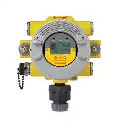
XNX Universal Transmitter
Section 2 - Installation and Operation
30
2.2 Wiring the XNX Transmitter
The XNX transmitter is available in sensor technologies, or
personality options, which support a variety of sensors and
applications. Each of the personalities use dedicated interface
boards. Pluggable terminal blocks are used for easy connection
and service. The personality boards and optional communication
interfaces are enclosed in plastic housings comprising the
electronics POD (Personality, Options, and Display). The
Personality circuit board determines the XNX behavior based on
the sensor type attached to the XNX interface (Figure 35). See
Specicationsfordriftandzerodeviationvalues.
ThistableillustratesthethreeXNXtransmittercongurations
and the sensors each support.
XNX IR Personality XNX EC Personality
Searchline Excel
Searchpoint Optima Plus Local/
Remote
XNX EC Sensor
Generic mA Sensors XNX EC Sensor Remote Mount Kit
XNX mV Personality
705 Local / Remote MPD Local (cat bead and IR) Sensepoint Local / Remote
705HT Local / Remote MPD Remote Sensepoint PPM Local/Remote
Sensepoint HT Remote
Figure 28. XNX Transmitter personalities
Caution: Before wiring the transmitter, confirm that the correct
personality and communication boards are installed.
2.2.1 General Wiring Considerations
For proper operation of the XNX Universal Transmitter and
sensor technologies, consideration of wiring-induced voltage
drops, transient electrical noise, and dissimilar earth ground
potentials is imperative in the design and installation of the
system.
EMI note for applications using shielded cable: Cable
shield must provide 90% coverage of the wiring. Cable
shield terminations must be made at the cable glands
with suitable EMI-type glands. Avoid terminating
cable shields at the earth ground lug inside the XNX
enclosure.
Loading
When wiring for DC power, 4-20mA signal, remote wiring to
sensorsmustbesizedsufcientlytoprovideadequatevoltages
for the line length and the loads that will be used.
Isolation
Isolating power and signal carrying conductors is recommended.
Circuit Protection
Supply circuits must provide over current protection. Class 2
power supplies are required for 24 volt DC supply. Consider
inrush current in specifying any DC supply. Power supply range
Loading ...
Loading ...
Loading ...
