Loading ...
Loading ...
Loading ...
EM-92
[VQ35DE]
CAMSHAFT
Revision: 2004 November 2004 FX35/FX45
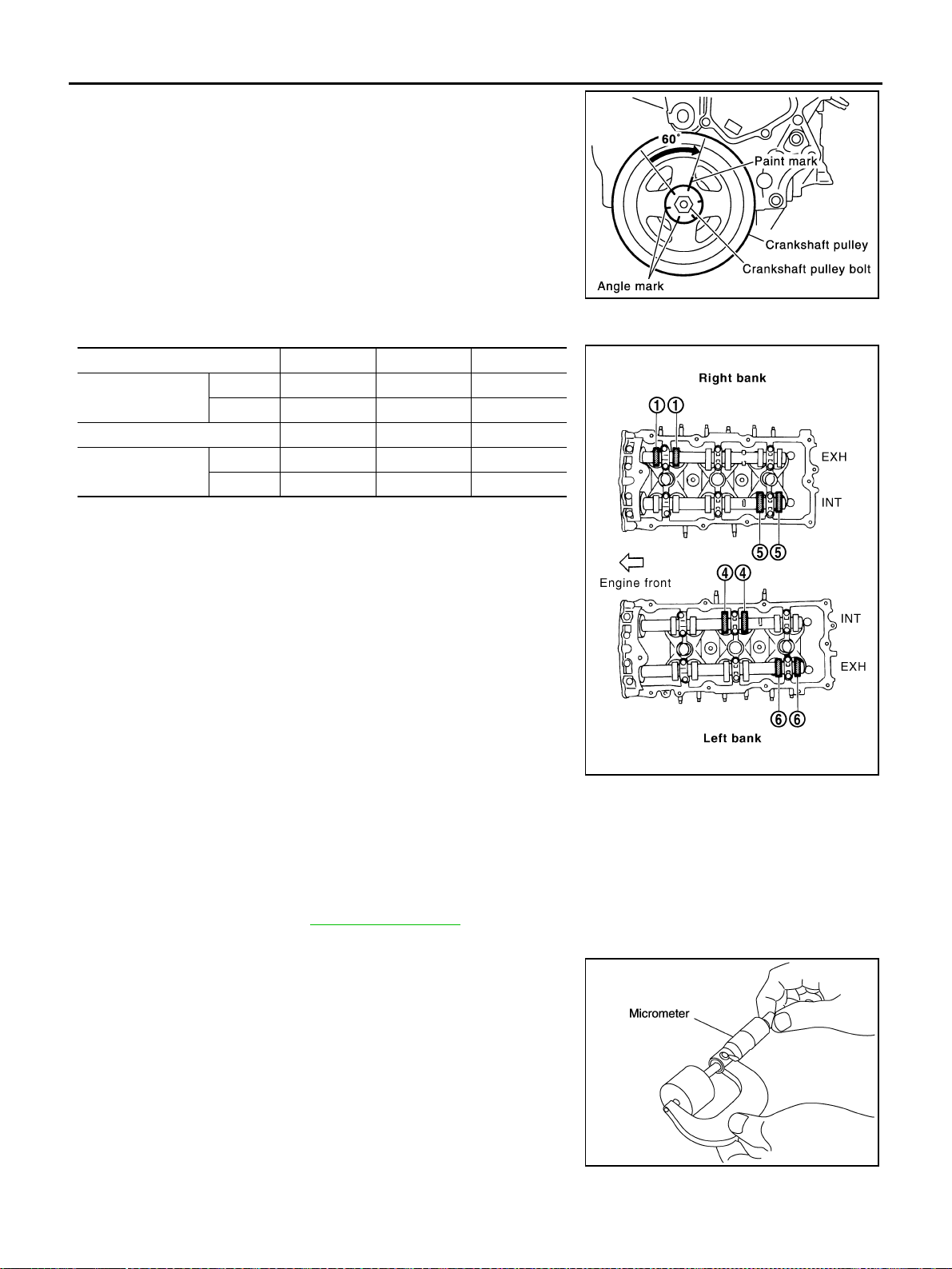
d. Rotate crankshaft by 240 degrees clockwise (when viewed from
engine front) to align No. 5 cylinder at TDC of compression
stroke.
● No. 5 cylinder at compression TDC
CAUTION:
If inspection was carried out with cold engine, make sure
values with fully warmed up engine are still within speci-
fications.
3. For measurements that are outside the specified range, perform adjustment below.
ADJUSTMENT
● Perform adjustment depending on selected head thickness of valve lifter.
● The specified valve lifter thickness is the dimension at normal temperatures. Ignore dimensional differ-
ences caused by temperature. Use the specifications for hot engine condition to adjust.
1. Remove camshaft. Refer to EM-83, "
REMOVAL" .
2. Remove valve lifters at the locations that are outside the standard.
3. Measure the center thickness of the removed valve lifters with a
micrometer.
4. Use the equation below to calculate valve lifter thickness for replacement.
SEM751G
Measuring position (right bank) No. 1 CYL. No. 3 CYL. No. 5 CYL.
No. 5 cylinder at
TDC
EXH ×
INT ×
Measuring position (left bank) No. 2 CYL. No. 4 CYL. No. 6 CYL.
No. 5 cylinder at
TDC
INT ×
EXH ×
PBIC2056E
KBIA0057E
Loading ...
Loading ...
Loading ...