Loading ...
Loading ...
Loading ...
INTAKE MANIFOLD
EM-175
[VK45DE]
C
D
E
F
G
H
I
J
K
L
M
A
EM
Revision: 2004 November 2004 FX35/FX45
1. Remove engine cover with power tool. Refer to EM-168, "ENGINE ROOM COVER" .
2. Release fuel pressure. Refer to EC-700, "
FUEL PRESSURE RELEASE" .
3. Drain engine coolant. Refer to CO-36, "
Changing Engine Coolant" .
4. Remove air duct (inlet), air cleaner case and mass air flow sensor assembly, air duct and resonator
assembly. Refer to EM-172, "
AIR CLEANER AND AIR DUCT" .
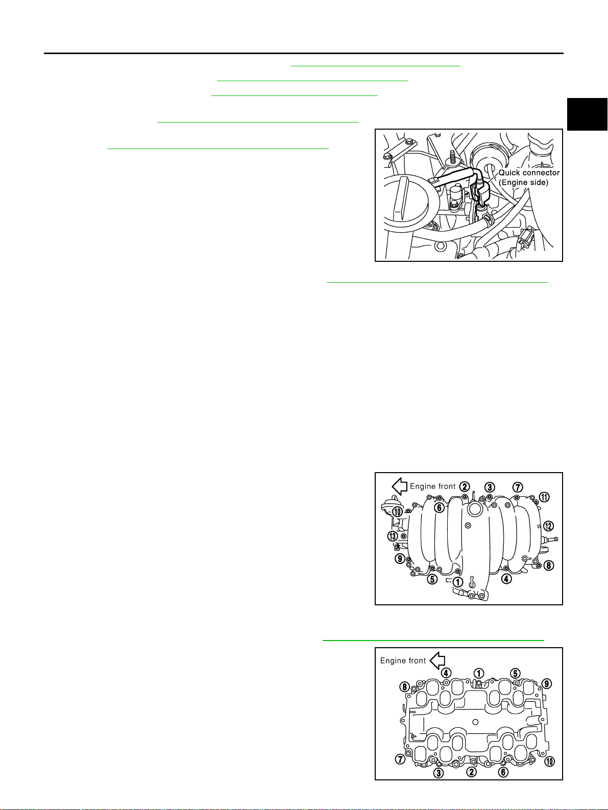
5. Disconnect fuel feed hose quick connector on engine side.
Refer to EM-188, "
FUEL INJECTOR AND FUEL TUBE" .
6. Remove fuel damper and fuel hose assembly. Refer to EM-188, "
FUEL INJECTOR AND FUEL TUBE" .
CAUTION:
● While hoses are disconnected, plug them to prevent fuel from draining.
● Do not separate fuel damper and fuel hose.
7. Remove or disconnect harnesses, brackets, vacuum hose, vacuum gallery and PCV hose and tube from
intake manifold (upper).
8. Remove electric throttle control actuator as follows:
a. Disconnect harness connector.
b. Loosen mounting bolts diagonally.
CAUTION:
● Handle carefully to avoid any shock to electric throttle control actuator.
● Do not disassemble.
9. Disconnect water hoses from water gallery.
10. Remove intake manifold adaptor and water gallery.
11. Loosen bolts in reverse order as shown in the figure to remove
intake manifold (upper) with power tool.
12. Remove vacuum tank form intake manifold (lower).
13. Remove fuel injector and fuel tube assembly. Refer to EM-188, "
FUEL INJECTOR AND FUEL TUBE" .
14. Loosen bolts in reverse order as shown in the figure to remove
intake manifold (lower) with power tool.
SBIA0353E
PBIC0014E
PBIC0015E
Loading ...
Loading ...
Loading ...