Loading ...
Loading ...
Loading ...
FUEL INJECTOR AND FUEL TUBE
EM-49
[VQ35DE]
C
D
E
F
G
H
I
J
K
L
M
A
EM
Revision: 2004 November 2004 FX35/FX45
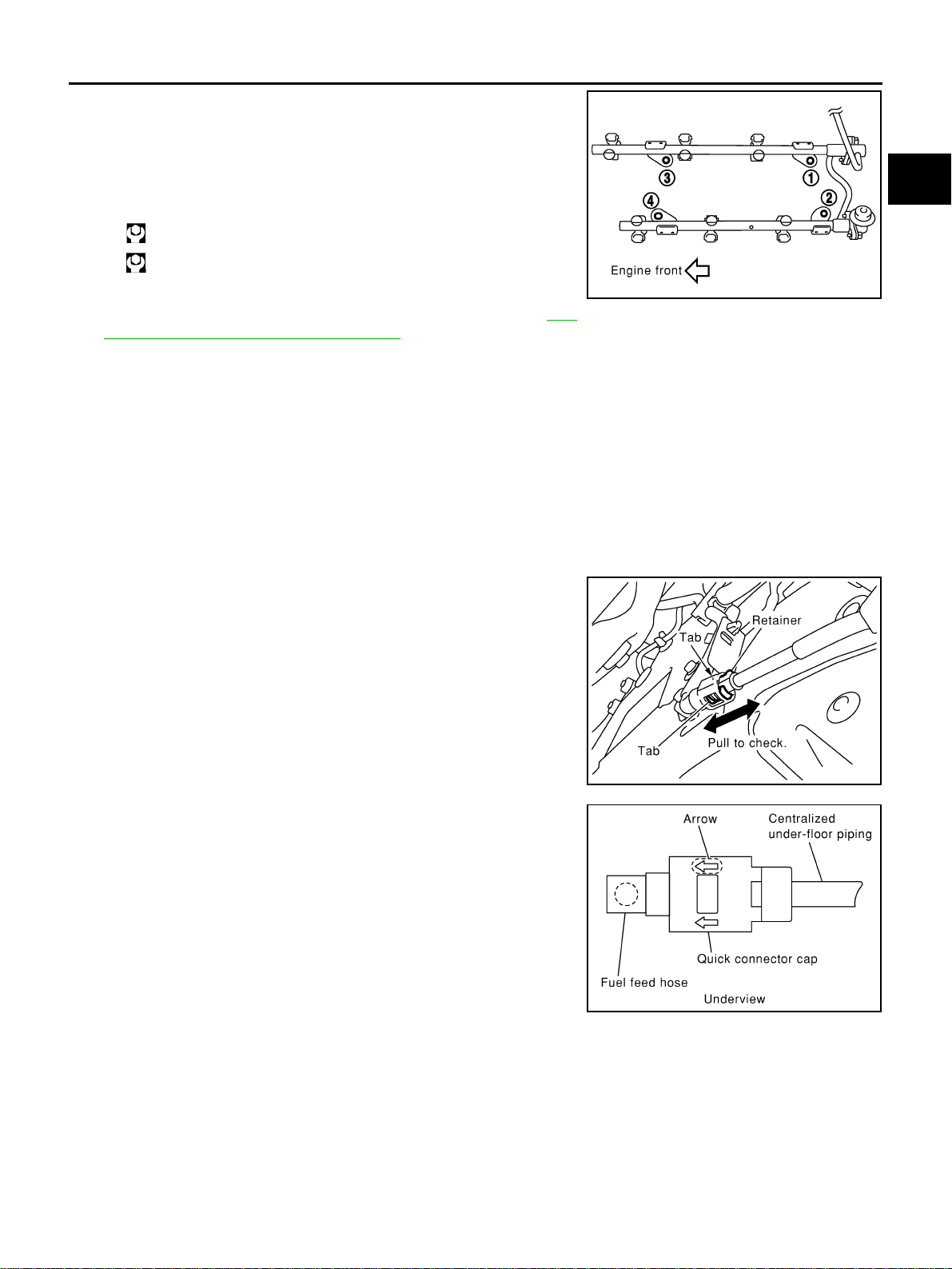
5. Install fuel tube and fuel injector assembly to intake manifold.
CAUTION:
Be careful not to let tip of injector nozzle come in contact
with other parts.
● Tighten mounting bolts in two steps in numerical order shown
in figure.
6. Connect injector sub-harness.
7. Install intake manifold collector (upper and lower). Refer to EM-
19, "INTAKE MANIFOLD COLLECTOR" .
8. Install fuel sub-tube on rear end of intake manifold collector (lower).
9. Connect fuel feed hose (with damper).
● Handling procedure of O-ring is the same as that of fuel damper and fuel sub-tube.
● Insert fuel damper straight into fuel sub-tube.
● Tighten mounting bolts evenly in turn.
● After tightening mounting bolts, make sure that there is no gap between flange and fuel sub-tube.
10. Connect quick connector between fuel feed hose and centralized under-floor piping connection with the
following procedure:
a. Check the connection for damage and foreign materials.
b. Align connector with tube, then insert connector straight into tube until a click is heard.
c. After connecting quick connector, use the following method to
make sure it is full connected.
● Visually confirm that the two retainer tabs are connected to
connector.
● Pull tube and connector to make sure they are securely con-
nected.
d. Install quick connector cap to quick connector connection.
● Install quick connector cap with arrow on surface facing in
direction of quick connector (fuel feed hose side).
CAUTION:
If cap cannot be installed smoothly, quick connector may
have not been installed correctly. Check connection
again.
e. Secure fuel feed hose to clamp.
11. Install in the reverse order of removal after this step.
INSPECTION AFTER INSTALLATION
Check on Fuel Leakage
● After installing fuel tubes, make sure there is no fuel leakage at connections in the following steps.
– a) Apply fuel pressure to fuel lines with turning ignition switch “ON” (with engine stopped). Then check for
fuel leaks at connections.
– b) Start engine and rev it up and check for fuel leaks at connections.
NOTE:
Use mirrors for checking on invisible points.
1st step: 10.1 N·m (1.0 kg-m, 7 ft-lb)
2nd step: 23.6 N·m (2.4 kg-m, 17 ft-lb)
KBIA1296E
KBIA1297E
KBIA1298E
Loading ...
Loading ...
Loading ...