Search
Home
Bookmarks
Brands
Articles
About us
Home
Infiniti
Infiniti 2004 INFINITI FX45 User Manual
Page 134
User Manual - Page 134
For 2004 INFINITI FX45.
Page 134/278
Page 1
Page 2
Page 3
Page 4
Page 5
Page 6
Page 7
Page 8
Page 9
Page 10
Page 11
Page 12
Page 13
Page 14
Page 15
Page 16
Page 17
Page 18
Page 19
Page 20
Page 21
Page 22
Page 23
Page 24
Page 25
Page 26
Page 27
Page 28
Page 29
Page 30
Page 31
Page 32
Page 33
Page 34
Page 35
Page 36
Page 37
Page 38
Page 39
Page 40
Page 41
Page 42
Page 43
Page 44
Page 45
Page 46
Page 47
Page 48
Page 49
Page 50
Page 51
Page 52
Page 53
Page 54
Page 55
Page 56
Page 57
Page 58
Page 59
Page 60
Page 61
Page 62
Page 63
Page 64
Page 65
Page 66
Page 67
Page 68
Page 69
Page 70
Page 71
Page 72
Page 73
Page 74
Page 75
Page 76
Page 77
Page 78
Page 79
Page 80
Page 81
Page 82
Page 83
Page 84
Page 85
Page 86
Page 87
Page 88
Page 89
Page 90
Page 91
Page 92
Page 93
Page 94
Page 95
Page 96
Page 97
Page 98
Page 99
Page 100
Page 101
Page 102
Page 103
Page 104
Page 105
Page 106
Page 107
Page 108
Page 109
Page 110
Page 111
Page 112
Page 113
Page 114
Page 115
Page 116
Page 117
Page 118
Page 119
Page 120
Page 121
Page 122
Page 123
Page 124
Page 125
Page 126
Page 127
Page 128
Page 129
Page 130
Page 131
Page 132
Page 133
Page 134
Page 135
Page 136
Page 137
Page 138
Page 139
Page 140
Page 141
Page 142
Page 143
Page 144
Page 145
Page 146
Page 147
Page 148
Page 149
Page 150
Page 151
Page 152
Page 153
Page 154
Page 155
Page 156
Page 157
Page 158
Page 159
Page 160
Page 161
Page 162
Page 163
Page 164
Page 165
Page 166
Page 167
Page 168
Page 169
Page 170
Page 171
Page 172
Page 173
Page 174
Page 175
Page 176
Page 177
Page 178
Page 179
Page 180
Page 181
Page 182
Page 183
Page 184
Page 185
Page 186
Page 187
Page 188
Page 189
Page 190
Page 191
Page 192
Page 193
Page 194
Page 195
Page 196
Page 197
Page 198
Page 199
Page 200
Page 201
Page 202
Page 203
Page 204
Page 205
Page 206
Page 207
Page 208
Page 209
Page 210
Page 211
Page 212
Page 213
Page 214
Page 215
Page 216
Page 217
Page 218
Page 219
Page 220
Page 221
Page 222
Page 223
Page 224
Page 225
Page 226
Page 227
Page 228
Page 229
Page 230
Page 231
Page 232
Page 233
Page 234
Page 235
Page 236
Page 237
Page 238
Page 239
Page 240
Page 241
Page 242
Page 243
Page 244
Page 245
Page 246
Page 247
Page 248
Page 249
Page 250
Page 251
Page 252
Page 253
Page 254
Page 255
Page 256
Page 257
Page 258
Page 259
Page 260
Page 261
Page 262
Page 263
Page 264
Page 265
Page 266
Page 267
Page 268
Page 269
Page 270
Page 271
Page 272
Page 273
Page 274
Page 275
Page 276
Page 277
Page 278
Contents
Table of Contents
Search
Previous
Next
Troubleshooting
Bookmarks
Loading ...
Loading ...
Loading ...
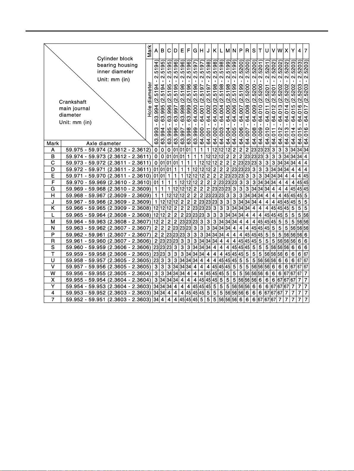
EM-134
[VQ35DE]
CYLINDER BLOCK
Revis
ion: 2004 N
ovemb
er
2004 FX
35/FX45
Main Bearing Selection T
able
PBIC0814
E
Loading ...
Loading ...
Loading ...
<
131
132
133
134
135
136
>
File type: PDF
File name: 2004-infiniti-fx45.pdf
File size: 11.19 MB
File Language: English
Pages: 278
Author: Infiniti
Published: 2021-01-07
Updated: 2023-06-13
Download File
Table of Contents
×
Table of Contents
1
VQ35DE
5
PRECAUTIONS
5
Precautions Necessary for Steering Wheel Rotation After Battery Disconnect
5
OPERATION PROCEDURE
5
Precautions for Drain Engine Coolant
5
Precautions for Disconnecting Fuel Piping
5
Precautions for Removal and Disassembly
5
Precautions for Inspection, Repair and Replacement
5
Precautions for Assembly and Installation
5
Parts Requiring Angle Tightening
6
Precautions for Liquid Gasket
6
REMOVAL OF LIQUID GASKET SEALING
6
LIQUID GASKET APPLICATION PROCEDURE
6
PREPARATION
8
Special Service Tools
8
Commercial Service Tools
10
NOISE, VIBRATION AND HARSHNESS (NVH) TROUBLESHOOTING
13
NVH Troubleshooting âEngine Noise
13
Use the Chart Below to Help You Find the Cause of the Symptom.
14
DRIVE BELTS
15
Checking Drive Belts
15
Tension Adjustment
15
ALTERNATOR AND POWER STEERING OIL PUMP BELT
16
AIR CONDITIONER COMPRESSOR BELT
16
Removal and Installation
16
REMOVAL
16
INSTALLATION
16
AIR CLEANER AND AIR DUCT
17
Removal and Installation
17
REMOVAL
17
INSTALLATION
17
Changing Air Cleaner Filter
18
INSPECTION
18
REMOVAL
18
INSTALLATION
18
INTAKE MANIFOLD COLLECTOR
19
Removal and Installation
19
REMOVAL
19
INSPECTION AFTER REMOVAL
21
Surface Distortion
21
INSTALLATION
22
Part Installation Direction
22
Intake Manifold Collector (Lower)
22
Intake Manifold Collector (Upper)
22
Water Hose
22
Electric Throttle Control Actuator
23
INTAKE MANIFOLD
24
Removal and Installation
24
REMOVAL
24
INSPECTION AFTER REMOVAL
24
Surface Distortion
24
INSTALLATION
25
Intake Manifold
25
EXHAUST MANIFOLD AND THREE WAY CATALYST
26
Removal and Installation
26
REMOVAL
26
INSPECTION AFTER REMOVAL
28
Surface Distortion
28
INSTALLATION
28
Exhaust Manifold Gasket
28
Exhaust Manifold
28
Heated Oxygen Sensor
28
OIL PAN AND OIL STRAINER
30
Removal and Installation
30
2 WD MODEL
30
REMOVAL
30
INSPECTION AFTER REMOVAL
32
INSTALLATION
32
INSPECTION AFTER INSTALLATION
35
AWD MODEL
36
REMOVAL
36
INSPECTION AFTER REMOVAL
38
INSTALLATION
39
INSPECTION AFTER INSTALLATION
41
IGNITION COIL
42
Removal and Installation
42
REMOVAL
42
INSTALLATION
42
SPARK PLUG (PLATINUM-TIPPED TYPE)
43
Removal and Installation
43
REMOVAL
43
INSPECTION AFTER REMOVAL
43
INSTALLATION
44
FUEL INJECTOR AND FUEL TUBE
45
Removal and Installation
45
REMOVAL
46
INSTALLATION
47
INSPECTION AFTER INSTALLATION
49
Check on Fuel Leakage
49
ROCKER COVER
51
Removal and Installation
51
REMOVAL
51
INSTALLATION
52
FRONT TIMING CHAIN CASE
54
Removal and Installation
54
REMOVAL
54
INSTALLATION
58
INSPECTION AFTER INSTALLATION
62
TIMING CHAIN
63
Removal and Installation
63
REMOVAL
64
INSPECTION AFTER REMOVAL
71
Timing Chain
71
INSTALLATION
71
INSPECTION AFTER INSTALLATION
80
CAMSHAFT
82
Removal and Installation
82
REMOVAL
83
INSPECTION AFTER REMOVAL
84
Camshaft Runout
84
Camshaft Cam Height
84
Camshaft Journal Oil Clearance
84
Camshaft End Play
85
Camshaft Sprocket Runout
85
Valve Lifter
86
Valve Lifter Clearance
86
INSTALLATION
87
Valve Clearance
89
INSPECTION
89
ADJUSTMENT
92
OIL SEAL
94
Removal and Installation of Valve Oil Seal
94
REMOVAL
94
INSTALLATION
94
Removal and Installation of Front Oil Seal
95
REMOVAL
95
INSTALLATION
96
Removal and Installation of Rear Oil Seal
96
REMOVAL
96
INSTALLATION
96
CYLINDER HEAD
98
On-Vehicle Service
98
CHECKING COMPRESSION PRESSURE
98
Removal and Installation
99
REMOVAL
99
INSPECTION AFTER REMOVAL
100
Outer Diameter of Cylinder Head Bolts
100
Cylinder Head Distortion
100
INSTALLATION
101
Disassembly and Assembly
102
DISASSEMBLY
103
ASSEMBLY
103
Inspection After Disassembly
104
VALVE DIMENSIONS
104
VALVE GUIDE CLEARANCE
105
Valve Stem Diameter
105
Valve Guide Inner Diameter
105
Valve Guide Clearance
105
VALVE GUIDE REPLACEMENT
105
VALVE SEAT CONTACT
107
VALVE SEAT REPLACEMENT
107
VALVE SPRING SQUARENESS
108
VALVE SPRING DIMENSIONS AND VALVE SPRING PRESSURE LOAD
109
ENGINE ASSEMBLY
110
Removal and Installation
110
2 WD MODEL
110
REMOVAL
111
Outline
111
Preparation
111
Engine Room
111
Passenger Room Side
111
Vehicle Underbody
112
Removal Work
112
Separation Work
113
INSTALLATION
113
INSPECTION AFTER INSTALLATION
113
AWD MODEL
115
REMOVAL
115
Outline
115
Preparation
116
Engine Room
116
Passenger Room Side
116
Vehicle Underbody
117
Removal Work
117
Separation Work
117
INSTALLATION
118
INSPECTION AFTER INSTALLATION
118
CYLINDER BLOCK
120
Disassembly and Assembly
120
DISASSEMBLY
121
ASSEMBLY
126
How to Select Piston and Bearing
131
DESCRIPTION
131
HOW TO SELECT PISTON
131
When New Cylinder Block Is Used
131
When Cylinder Block Is Reused
132
Piston Selection Table
132
HOW TO SELECT CONNECTING ROD BEARING
132
When New Connecting Rod and Crankshaft are Used
132
When Crankshaft and Connecting Rod Are Reused
132
Connecting Rod Bearing Selection Table
132
Undersize Bearings Usage Guide
133
HOW TO SELECT MAIN BEARING
133
When New Cylinder Block and Crankshaft Are Used
133
When Cylinder Block and Crankshaft Are Reused
133
Main Bearing Selection Table
134
Main Bearing Grade Table (All Journals)
135
Undersize Bearing Usage Guide
135
Inspection After Disassembly
136
CRANKSHAFT END PLAY
136
CONNECTING ROD SIDE CLEARANCE
136
PISTON TO PISTON PIN OIL CLEARANCE
136
Piston Pin Hole Diameter
136
Piston Pin Outer Diameter
136
Piston to Piston Pin Oil Clearance
137
PISTON RING SIDE CLEARANCE
137
PISTON RING END GAP
137
CONNECTING ROD BEND AND TORSION
138
CONNECTING ROD BEARING HOUSING DIAMETER (BIG END)
138
CONNECTING ROD BUSHING OIL CLEARANCE (SMALL END)
138
Piston Pin Bushing Inner Diameter (Small End)
138
Piston Pin Outer Diameter
139
Connecting Rod Bushing Oil Clearance (Small End)
139
CYLINDER BLOCK DISTORTION
139
MAIN BEARING HOUSING INNER DIAMETER
140
PISTON TO CYLINDER BORE CLEARANCE
140
Cylinder Bore Inner Diameter
140
Piston Skirt Diameter
141
Piston-to-Cylinder Bore Clearance
141
Re-Boring Cylinder Bore
141
CRANKSHAFT MAIN JOURNAL DIAMETER
141
CRANKSHAFT PIN JOURNAL DIAMETER
142
CRANKSHAFT OUT-OF-ROUND AND TAPER
142
CRANKSHAFT RUNOUT
142
CONNECTING ROD BEARING OIL CLEARANCE
142
Method by Calculation
142
Method of Using Plastigage
143
MAIN BEARING OIL CLEARANCE
143
Method by Calculation
143
Method of Using Plastigage
143
MAIN BEARING CRUSH HEIGHT
144
CONNECTING ROD BEARING CRUSH HEIGHT
144
MAIN BEARING CAP BOLT OUTER DIAMETER
144
CONNECTING ROD BOLT OUTER DIAMETER
144
DRIVE PLATE
145
OIL JET
145
OIL JET RELIEF VALVE
145
SERVICE DATA AND SPECIFICATIONS (SDS)
146
Standard and Limit
146
GENERAL SPECIFICATIONS
146
DRIVE BELT
147
INTAKE MANIFOLD COLLECTOR, INTAKE MANIFOLD AND EXHAUST MANIFOLD
147
SPARK PLUG
147
CAMSHAFT AND CAMSHAFT BEARING
148
Valve Lifter
148
Valve Clearance
148
Available Valve Lifter
149
CYLINDER HEAD
150
Valve Dimensions
150
Valve Guide
151
Valve Seat
152
Valve Spring
152
CYLINDER BLOCK
153
PISTON, PISTON RING AND PISTON PIN
154
Available Piston
154
Piston Ring
154
Piston Pin
154
CONNECTING ROD
155
CRANKSHAFT
156
MAIN BEARING
157
Undersize
157
Main Bearing Oil Clearance
157
CONNECTING ROD BEARING
158
Undersize
158
Connecting Rod Bearing Oil Clearance
158
VK45DE
159
PRECAUTIONS
159
Precautions Necessary for Steering Wheel Rotation After Battery Disconnect
159
OPERATION PROCEDURE
159
Precautions for Drain Engine Coolant
159
Precautions for Disconnecting Fuel Piping
159
Precautions for Removal and Disassembly
159
Precautions for Inspection, Repair and Replacement
159
Precautions for Assembly and Installation
159
Parts Requiring Angle Tightening
160
Precautions for Liquid Gasket
160
REMOVAL OF LIQUID GASKET SEALING
160
LIQUID GASKET APPLICATION PROCEDURE
160
PREPARATION
162
Special Service Tools
162
Commercial Service Tools
164
NOISE, VIBRATION AND HARSHNESS (NVH) TROUBLESHOOTING
166
NVH Troubleshooting âEngine Noise
166
Use the Chart Below to Help You Find the Cause of the Symptom.
167
ENGINE ROOM COVER
168
Removal and Installation
168
REMOVAL
168
INSTALLATION
168
DRIVE BELTS
169
Checking Drive Belts
169
Tension Adjustment
169
Removal and Installation
169
REMOVAL
169
Alternator, Water Pump and A/C Compressor Belt
169
Power Steering Oil Pump Belt
170
INSTALLATION
170
Drive Belt Auto Tensioner and Idler Pulley
171
REMOVAL
171
INSTALLATION
171
AIR CLEANER AND AIR DUCT
172
Removal and Installation
172
REMOVAL
172
INSTALLATION
172
Changing Air Cleaner Filter
173
REMOVAL
173
INSTALLATION
173
INTAKE MANIFOLD
174
Removal and Installation
174
REMOVAL
174
INSPECTION AFTER REMOVAL
176
Surface Distortion
176
INSTALLATION
176
Intake Manifold (Lower)
176
Intake Manifold (Upper)
176
Electric Throttle Control Actuator
176
Water Hose
176
Vacuum Hose
176
INSPECTION AFTER INSTALLATION
177
EXHAUST MANIFOLD AND THREE WAY CATALYST
178
Removal and Installation
178
REMOVAL
178
INSPECTION AFTER REMOVAL
180
Surface Distortion
180
INSTALLATION
180
Exhaust Manifold Gasket
180
Exhaust Manifold
180
Heated Oxygen Sensor
180
OIL PAN AND OIL STRAINER
181
Removal and Installation
181
REMOVAL
181
INSPECTION AFTER REMOVAL
183
INSTALLATION
183
INSPECTION AFTER INSTALLATION
183
IGNITION COIL
185
Removal and Installation
185
REMOVAL
185
INSTALLATION
185
SPARK PLUG (PLATINUM-TIPPED TYPE)
186
Removal and Installation
186
REMOVAL
186
INSPECTION AFTER REMOVAL
186
INSTALLATION
187
FUEL INJECTOR AND FUEL TUBE
188
Removal and Installation
188
REMOVAL
188
INSTALLATION
190
INSPECTION AFTER INSTALLATION
192
Check on Fuel Leakage
192
ROCKER COVER
193
Removal and Installation
193
REMOVAL
193
INSTALLATION
195
TIMING CHAIN
196
Removal and Installation
196
REMOVAL
197
INSPECTION AFTER REMOVAL
201
Timing Chain
201
INSTALLATION
201
INSPECTION AFTER INSTALLATION
207
CAMSHAFT
208
Removal and Installation
208
REMOVAL
208
INSPECTION AFTER REMOVAL
209
Camshaft Runout
209
Camshaft Cam Height
209
Camshaft Journal Oil Clearance
210
Camshaft End Play
210
Camshaft Sprocket Runout
211
Valve Lifter and Adjusting Shim
211
Valve Lifter Clearance
211
INSTALLATION
212
Valve Clearance
214
INSPECTION
214
ADJUSTMENT
217
OIL SEAL
221
Removal and Installation of Valve Oil Seal
221
REMOVAL
221
INSTALLATION
221
Removal and Installation of Front Oil Seal
222
REMOVAL
222
INSTALLATION
222
Removal and Installation of Rear Oil Seal
223
REMOVAL
223
INSTALLATION
223
CYLINDER HEAD
224
On-Vehicle Service
224
CHECKING COMPRESSION PRESSURE
224
Removal and Installation
225
REMOVAL
225
INSPECTION AFTER REMOVAL
226
Cylinder Head Bolts Outer Diameter
226
Cylinder Head Distortion
226
INSTALLATION
226
Disassembly and Assembly
228
DISASSEMBLY
228
ASSEMBLY
229
Inspection After Disassembly
230
VALVE DIMENSIONS
230
VALVE GUIDE CLEARANCE
231
Valve Stem Diameter
231
Valve Guide Inner Diameter
231
Valve Guide Clearance
231
VALVE GUIDE REPLACEMENT
231
VALVE SEAT CONTACT
232
VALVE SEAT REPLACEMENT
233
VALVE SPRING SQUARENESS
234
VALVE SPRING DIMENSIONS AND VALVE SPRING PRESSURE LOAD
235
ENGINE ASSEMBLY
236
Removal and Installation
236
REMOVAL
236
Outline
236
Preparation
236
Engine Room LH
237
Engine Room RH
237
Vehicle underbody
237
Removal Work
238
Separation Work
238
INSTALLATION
239
INSPECTION AFTER INSTALLATION
239
CYLINDER BLOCK
240
Disassembly and Assembly
240
DISASSEMBLY
241
ASSEMBLY
244
How to Select Piston and Bearing
250
DESCRIPTION
250
HOW TO SELECT PISTON
250
When New Cylinder Block Is Used:
250
When Cylinder Block Is Reused:
250
Piston Selection Table
251
HOW TO SELECT CONNECTING ROD BEARING
251
When New Connecting Rod and Crankshaft Are Used:
251
When Crankshaft and Connecting Rod Are Reused:
251
Connecting Rod Bearing Selection Table
251
Under Size Bearings Usage Guide
251
HOW TO SELECT MAIN BEARING
252
When New Cylinder Block and Crankshaft Are Used:
252
When Cylinder Block and Crankshaft Are Reused:
253
Main Bearing Selection Table (No. 1 and 5 Journal)
253
Main Bearing Selection Table (No. 2, 3 and 4 Journal)
254
Main Bearing Grade Table (All Journals)
255
Use Undersize Bearing Usage Guide
255
Inspection After Disassembly
256
CRANKSHAFT END PLAY
256
CONNECTING ROD SIDE CLEARANCE
256
PISTON TO PISTON PIN OIL CLEARANCE
256
Piston Pin Hole Diameter
256
Piston Pin Outer Diameter
256
Piston to Piston Pin Oil Clearance
256
PISTON RING SIDE CLEARANCE
257
PISTON RING END GAP
257
CONNECTING ROD BEND AND TORSION
258
CONNECTING ROD BIG END DIAMETER
258
CONNECTING ROD BUSHING OIL CLEARANCE
258
Connecting Rod Bushing Inner Diameter
258
Piston Pin Outer Diameter
259
Connecting Rod Bushing Oil Clearance
259
CYLINDER BLOCK DISTORTION
259
MAIN BEARING HOUSING INNER DIAMETER
260
PISTON TO CYLINDER BORE CLEARANCE
260
Cylinder Bore Inner Diameter
260
Piston Skirt Diameter
261
Piston to Cylinder Bore Clearance
261
Re-Boring Cylinder Bore
261
CRANKSHAFT MAIN JOURNAL DIAMETER
261
CRANKSHAFT PIN JOURNAL DIAMETER
262
CRANKSHAFT OUT-OF-ROUND AND TAPER
262
CRANKSHAFT RUNOUT
262
CONNECTING ROD BEARING OIL CLEARANCE
263
Method by Calculation
263
Method of Using Plastigage
263
MAIN BEARING OIL CLEARANCE
264
Method by Calculation
264
Method of Using Plastigage
264
CRUSH HEIGHT OF MAIN BEARING
265
CRUSH HEIGHT OF CONNECTING ROD BEARING
265
DRIVE PLATE
265
SERVICE DATA AND SPECIFICATIONS (SDS)
266
Standard and Limit
266
GENERAL SPECIFICATIONS
266
DRIVE BELTS
266
INTAKE MANIFOLD AND EXHAUST MANIFOLD
266
SPARK PLUG
267
CAMSHAFT AND CAMSHAFT BEARING
267
Valve Lifter
267
Valve Clearance
267
Available Adjusting Shims
268
CYLINDER HEAD
269
Valve Dimensions
270
Valve Guide
270
Valve Seat
271
Valve Spring
271
CYLINDER BLOCK
272
PISTON, PISTON RING AND PISTON PIN
273
Available Piston
273
Piston Ring
273
Piston Pin
273
CONNECTING ROD
274
CRANKSHAFT
275
MAIN BEARING
277
Undersize
277
Main Bearing Oil Clearance
278
CONNECTING ROD BEARING
278
Undersize
278
Connecting Rod Bearing Oil Clearance
278
Search:
×
Search