Loading ...
Loading ...
Loading ...
EM-214
[VK45DE]
CAMSHAFT
Revision: 2004 November 2004 FX35/FX45
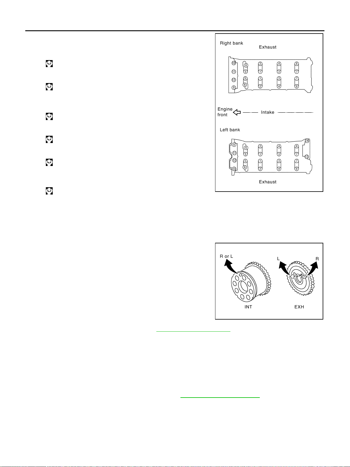
4. Tighten camshaft bracket bolts in the following steps, in numeri-
cal order as shown in the figure.
a. Tighten No. 9 to 12 in numerical order as shown.
b. Tighten No. 1 to 8 in numerical order as shown.
c. Tighten No. 13 to 14 in numerical order as shown. (Left bank
only)
d. Tighten all bolts in numerical order as shown.
e. Tighten No. 1 to 12 in numerical order as shown.
f. Tighten No. 13 to 14 in numerical order as shown. (Left bank
only)
CAUTION:
After tightening mounting bolts of camshaft brackets, be sure to wipe off excessive liquid gasket
from the parts listed below.
● Mating surface of rocker cover
● Mating surface of front cover
5. Install camshaft sprockets.
● Install by checking with identification mark on surface.
● Instal camshaft sprocket (EXH) by selectively using the
groove of dowel pin according to the bank. (Common part
used for both banks.)
● Lock the hexagonal part of camshaft in the same way as for
removal, and tighten mounting bolts.
6. Check and adjust valve clearance. Refer to EM-214, "
Valve Clearance" .
7. Install in the reverse order of removal after this step.
Valve Clearance ABS006IL
INSPECTION
In cases of removing/installing or replacing camshaft and valve-related parts, or of unusual engine conditions
due to changes in valve clearance (found malfunctions during starting, idling or causing noise), perform
inspection as follows:
1. Warm up engine. Then stop it.
2. Remove rocker covers (right and left bank). Refer to EM-193, "
ROCKER COVER" .
3. Measure valve clearance as follows:
a. Set No. 1 cylinder at TDC of its compression stroke.
: 1.96 N·m (0.2 kg-m, 1 ft-lb)
: 1.96 N·m (0.2 kg-m, 1 ft-lb)
: 1.96 N·m (0.2 kg-m, 1 ft-lb)
: 5.88 N·m (0.6 kg-m, 4 ft-lb)
: 10.41 N·m (1.1 kg-m, 8 ft-lb)
: 31.35 N·m (3.2 kg-m, 23 ft-lb)
PBIC0031E
PBIC2345E
Loading ...
Loading ...
Loading ...