Loading ...
Loading ...
Loading ...
EM-112
[VQ35DE]
ENGINE ASSEMBLY
Revision: 2004 November 2004 FX35/FX45
a. Remove passenger-side kicking plate, dash side finisher, and
glove box. Refer to EI-37, "
BODY SIDE TRIM" and IP-10,
"INSTRUMENT PANEL ASSEMBLY" .
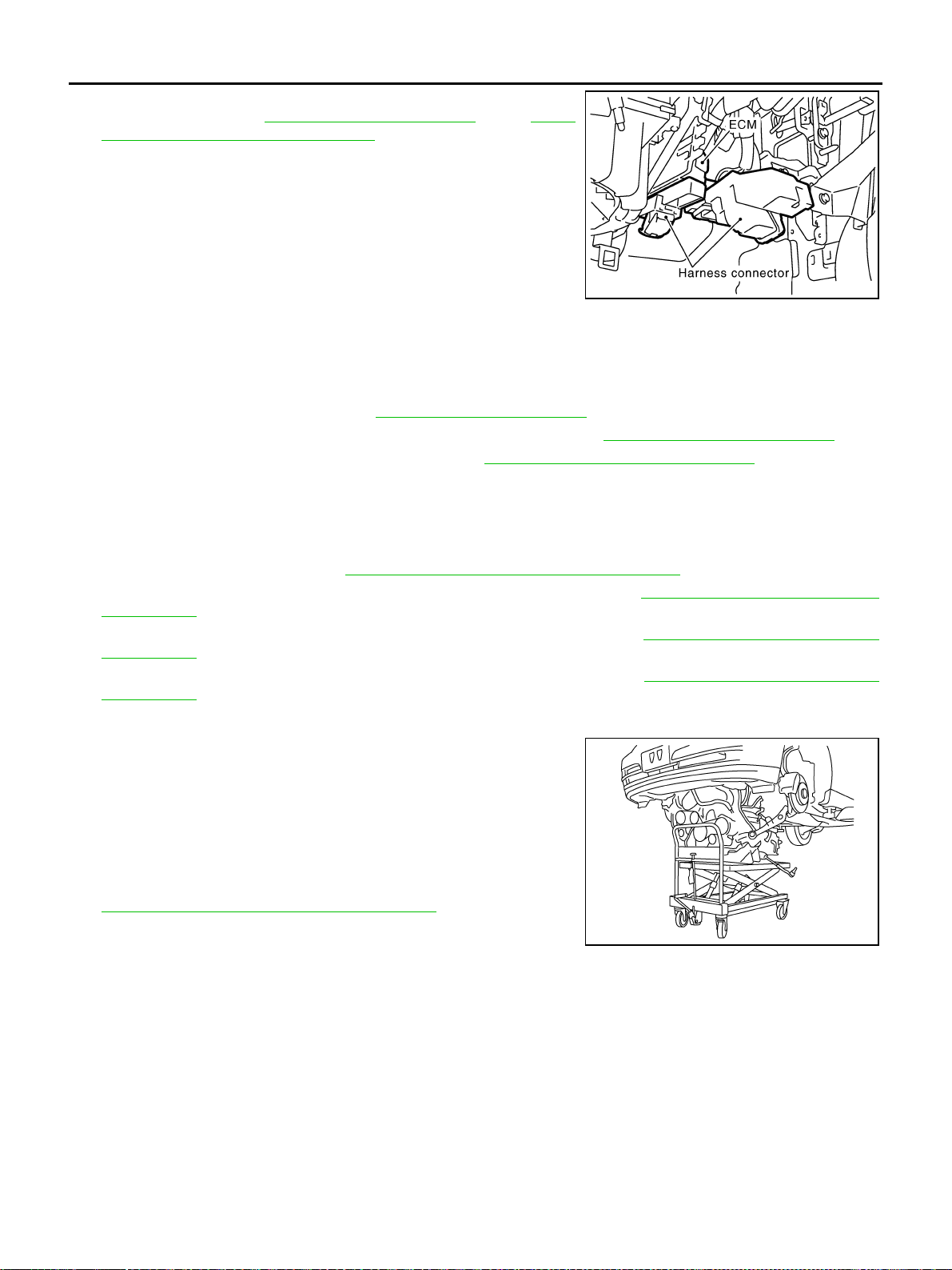
b. Disconnect engine room harness connectors at unit sides ECM
and other.
c. Disengage intermediate fixing point. Pull out engine room har-
nesses to engine room side, and temporarily secure them on
engine.
CAUTION:
● When pulling out harnesses, take care not to damage
harnesses and connectors.
● After temporarily securing, cover connectors with vinyl or similar material to protect against for-
eign material adhesion.
Vehicle Underbody
1. Remove A/T fluid cooler hoses and power steering oil pump oil cooler hoses.
2. Remove exhaust front tube. Refer to EX-3, "EXHAUST SYSTEM" .
3. Disconnect steering lower joint, and release steering shaft. Refer to PS-12, "
STEERING COLUMN" .
4. Separate transmission and propeller shaft. Refer to PR-6, "
REAR PROPELLER SHAFT" .
5. Disengage shift control linkage at selector lever side. Then, temporarily secure it on transmission, so that
it does not sag.
6. Remove rear plate cover from upper oil pan. Then, remove bolts fixing drive plate to torque converter.
7. Remove bolts fixing transmission to lower rear side of upper oil pan.
8. Remove front stabilizer. Refer to FSU-6, "
FRONT SUSPENSION ASSEMBLY" .
9. Remove LH and RH sides tie-rod ends from steering knuckle. Refer to FSU-6, "
FRONT SUSPENSION
ASSEMBLY" .
10. Remove lower ends of LH and RH sides struts from lower arms. Refer to FSU-6, "
FRONT SUSPENSION
ASSEMBLY" .
11. Remove LH and RH sides lower arms from suspension member. Refer to FSU-6, "
FRONT SUSPENSION
ASSEMBLY" .
Removal Work
1. Use a manual lift table caddy (commercial service tool) or equiv-
alently rigid tool such as a transmission jack. Securely support
bottom of suspension member and transmission.
CAUTION:
Put a piece of wood or something similar as the supporting
surface, secure a completely stable condition.
2. Remove rear member mounting bolt.
3. Remove suspension member mounting bolt and nut. Refer to
FSU-6, "
FRONT SUSPENSION ASSEMBLY" .
4. Carefully lower jack to remove engine, transmission, and sus-
pension member assembly. When performing work, observe the
following:
CAUTION:
● Confirm there is no interference with vehicle.
● Make sure all connection points have been disconnected.
● Keep in mind the center of vehicle gravity changes. If necessary, use jack(s) to support vehicle
at rear jacking point(s) to prevent it from falling it off lift.
SBIA0473E
PBIC0804E
Loading ...
Loading ...
Loading ...