Loading ...
Loading ...
Loading ...
EM-100
[VQ35DE]
CYLINDER HEAD
Revision: 2004 November 2004 FX35/FX45
NOTE:
At the time of the start of this procedure front suspension member is removed, and cylinder head is
hanged by hoist with engine slinger installed.
3. Release hoist from hanging, then remove engine slinger.
4. Remove the following components and related parts:
● Fuel tube and fuel injector assembly. Refer to EM-45, "FUEL INJECTOR AND FUEL TUBE" .
● Intake manifold. Refer to EM-24, "INTAKE MANIFOLD" .
● Exhaust manifold. Refer to EM-26, "EXHAUST MANIFOLD AND THREE WAY CATALYST" .
● Water inlet and thermostat assembly. Refer to CO-26, "WATER INLET AND THERMOSTAT ASSEM-
BLY" .
● Water outlet and water piping. Refer to CO-28, "WATER OUTLET AND WATER PIPING" .
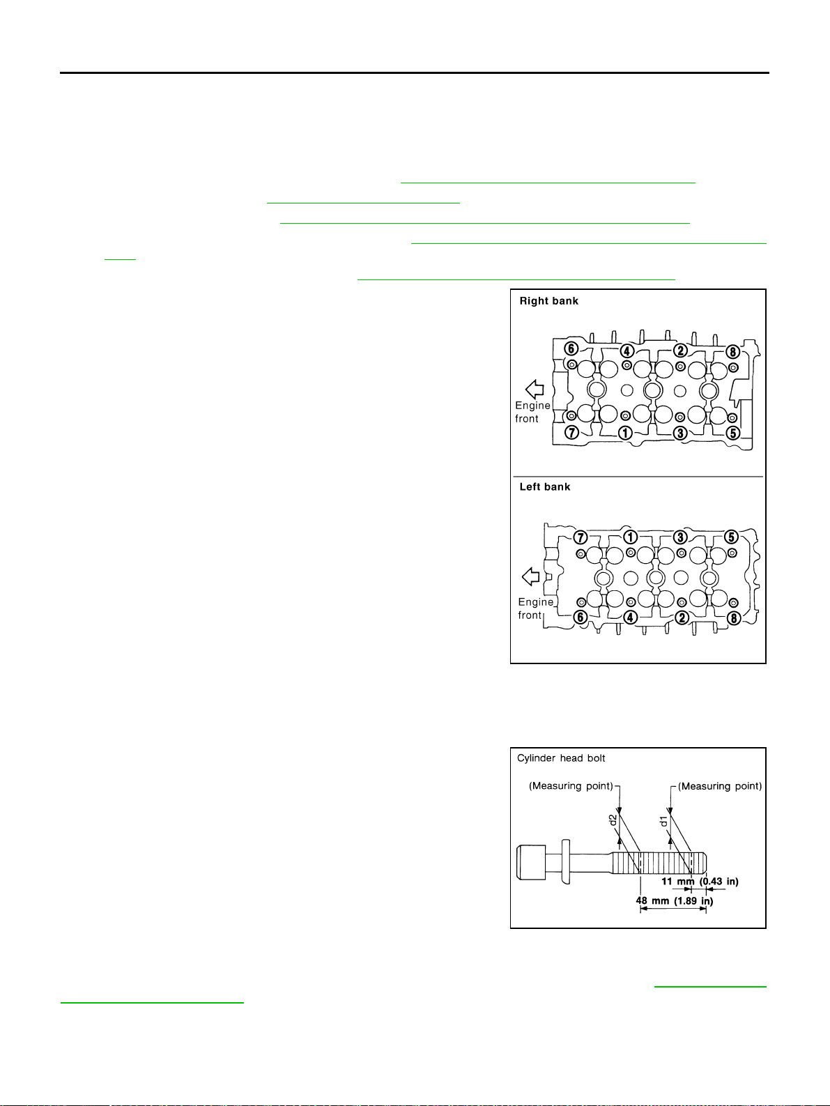
5. Remove cylinder head loosening bolts with power tool in reverse
order shown in the figure and using cylinder head bolt wrench
(commercial service tool).
6. Remove cylinder head gaskets.
INSPECTION AFTER REMOVAL
Outer Diameter of Cylinder Head Bolts
● Cylinder head bolts are tightened by plastic zone tightening
method. Whenever the size difference between d1 and d2
exceeds the limit, replace them with new one.
● If reduction of outer diameter appears in a position other than
d2, use it as d2 point.
Cylinder Head Distortion
NOTE:
When performing this inspection, cylinder block distortion should be also checking. Refer to EM-139, "
CYLIN-
DER BLOCK DISTORTION" .
1. Using scraper, wipe off oil, scale, gasket, sealant and carbon deposits from surface of cylinder head.
CAUTION:
Do not allow gasket fragments to enter engine oil or engine coolant passages.
PBIC2057E
Limit (d1 - d2) : 0.11 mm (0.0043 in)
SEM957E
Loading ...
Loading ...
Loading ...