Loading ...
Loading ...
Loading ...
EM-176
[VK45DE]
INTAKE MANIFOLD
Revision: 2004 November 2004 FX35/FX45
15. Remove intake manifold gaskets.
CAUTION:
Cover engine openings to avoid entry of foreign materials.
INSPECTION AFTER REMOVAL
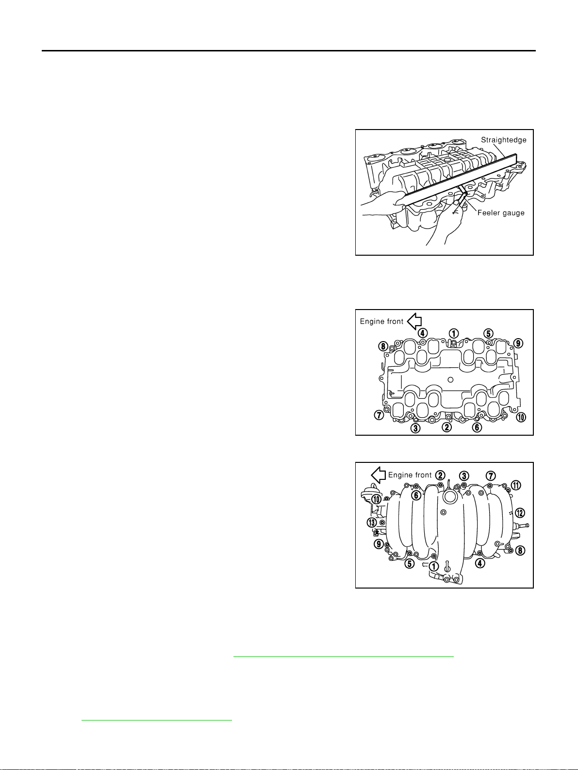
Surface Distortion
● Check the surface distortion of both the intake manifold (upper
and lower) mating surfaces with straightedge and feeler gauge.
● If it exceeds the limit, replace intake manifolds (lower and/or
upper).
INSTALLATION
Note to the following, and install in the reverse order of removal:
Intake Manifold (Lower)
Tighten in numerical order as shown in the figure.
● There are two types of mounting bolts. Refer to the following for
locating bolts.
Intake Manifold (Upper)
Tighten in numerical order as shown in the figure.
● There are two types of mounting bolts. Refer to the following for
locating bolts
Electric Throttle Control Actuator
● Install intake manifold adapter gasket and electric throttle control actuator gasket so that three protrusions
for installation identification do not face downward.
● Tighten mounting bolts of electric throttle control actuator equally and diagonally in several steps.
● After installation perform procedure in EM-177, "INSPECTION AFTER INSTALLATION" .
Water Hose
Insert hose by 27 to 32 mm (1.06 to 1.26 in) from connector end.
Vacuum Hose
Refer to EC-677, "Vacuum Hose Drawing" .
Limit : 0.1 mm (0.004 in)
PBIC0016E
M8 × 90 mm (3.54 in) : 7, 8
M8 × 35 mm (1.38 in) Except the above
PBIC0015E
M8 × 80 mm (3.15 in) : 4, 5, 6, 7
M8 × 25 mm (0.98 in) : Except the above
PBIC0014E
Loading ...
Loading ...
Loading ...