Loading ...
Loading ...
Loading ...
OIL PAN AND OIL STRAINER
EM-37
[VQ35DE]
C
D
E
F
G
H
I
J
K
L
M
A
EM
Revision: 2004 November 2004 FX35/FX45
8. Remove air hose from air duct to mass air flow sensor side and electric throttle control actuator side.
Refer to EM-17, "
AIR CLEANER AND AIR DUCT" .
9. Remove drive belt for alternator and power steering pump and A/C compressor. Refer to EM-15, "
DRIVE
BELTS" .
10. Remove front drive shaft (LH and RH) and side shaft. Refer to FAX-12, "
FRONT DRIVE SHAFT" .
11. Remove side shaft. Refer to FFD-10, "
FRONT FINAL DRIVE ASSEMBLY" .
12. Removal engine rear lower slinger, and install engine rear slinger to sling engine assembly for positioning.
Refer to EM-8, "
Special Service Tools" .
13. Remove front suspension member. Refer to Refer to FSU-17, "
FRONT SUSPENSION MEMBER" .
14. Remove engine mounting bracket, engine mounting bracket (lower) and insulator. Refer to EM-110,
"ENGINE ASSEMBLY" .
15. Remove front propeller shaft. Refer to PR-4, "
FRONT PROPELLER SHAFT" .
16. Remove oil filter and oil filter bracket. Refer to LU-12, "
OIL FILTER BRACKET (AWD)" .
17. Remove alternator stay. Refer to SC-23, "
CHARGING SYSTEM" .
18. Remove alternator and power steering pump and A/C compressor idler pulley and bracket. Refer to EM-
15, "DRIVE BELTS" .
19. Disconnect A/T fluid cooler hoses, and remove oil cooler water pipe mounting bolt. Refer to LU-14, "
OIL
COOLER" .
20. Disconnect A/T fluid cooler tube.
21. Remove front final drive assembly. Refer to FFD-10, "
FRONT FINAL DRIVE ASSEMBLY" .
22. Remove starter motor. Refer to SC-10, "
STARTING SYSTEM" .
23. Remove crankshaft position sensor (POS).
CAUTION:
● Handle carefully to avoid dropping and shocks.
● Do not disassemble.
● Do not allow metal powder to adhere to magnetic part at sensor tip.
● Do not place sensors in a location where they are exposed to magnetism.
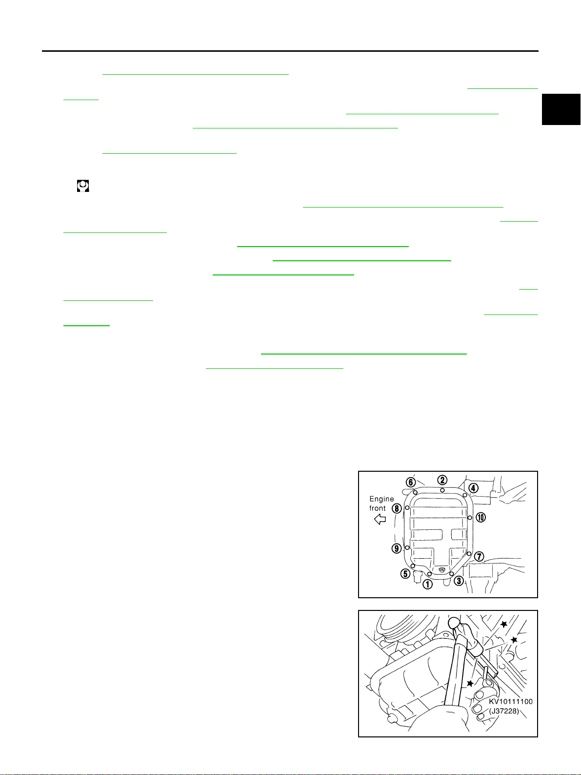
24. Remove oil pan (lower) as the following:
a. Loosen bolts in reverse order as shown in the figure to remove.
b. Insert seal cutter (SST) between oil pan (upper) and oil pan
(lower).
c. Slide seal cutter by tapping on the side of tool with hammer.
Remove oil pan (lower).
CAUTION:
● Be careful not to damage the mating surface.
● Do not insert flat-bladed screwdriver, this will damage the
mating surface.
Slinger bolts:
: 28.0 N·m (2.9 kg-m, 21 ft-lb)
PBIC0782E
SEM960F
Loading ...
Loading ...
Loading ...