Loading ...
Loading ...
Loading ...
ENGINE ASSEMBLY
EM-117
[VQ35DE]
C
D
E
F
G
H
I
J
K
L
M
A
EM
Revision: 2004 November 2004 FX35/FX45
Vehicle Underbody
1. Remove A/T fluid cooler hoses and power steering oil pump oil cooler hoses.
2. Remove exhaust front tube. Refer to EX-3, "
EXHAUST SYSTEM" .
3. Disconnect steering lower joint, and release steering shaft. Refer to PS-12, "
STEERING COLUMN" .
4. Separate transmission and propeller shaft. Refer to PR-6, "
REAR PROPELLER SHAFT" .
5. Disengage shift control linkage at selector lever side. Then, temporarily secure it on transmission, so that
it does not sag.
6. Remove rear plate cover from upper oil pan. Then, remove bolts fixing drive plate to torque converter.
7. Remove bolts fixing transmission to lower rear side of upper oil pan.
8. Remove LH and RH sides tie-rod ends from steering knuckle. Refer to FSU-6, "
FRONT SUSPENSION
ASSEMBLY" .
9. Remove lower ends of LH and RH sides struts from lower arms. Refer to FSU-6, "
FRONT SUSPENSION
ASSEMBLY" .
10. Remove LH and RH sides lower arms from suspension member. Refer to FSU-6, "
FRONT SUSPENSION
ASSEMBLY" .
11. Remove LH and RH sides front drive shafts from LH and RH sides knuckles. Refer to FAX-12, "FRONT
DRIVE SHAFT" .
Removal Work
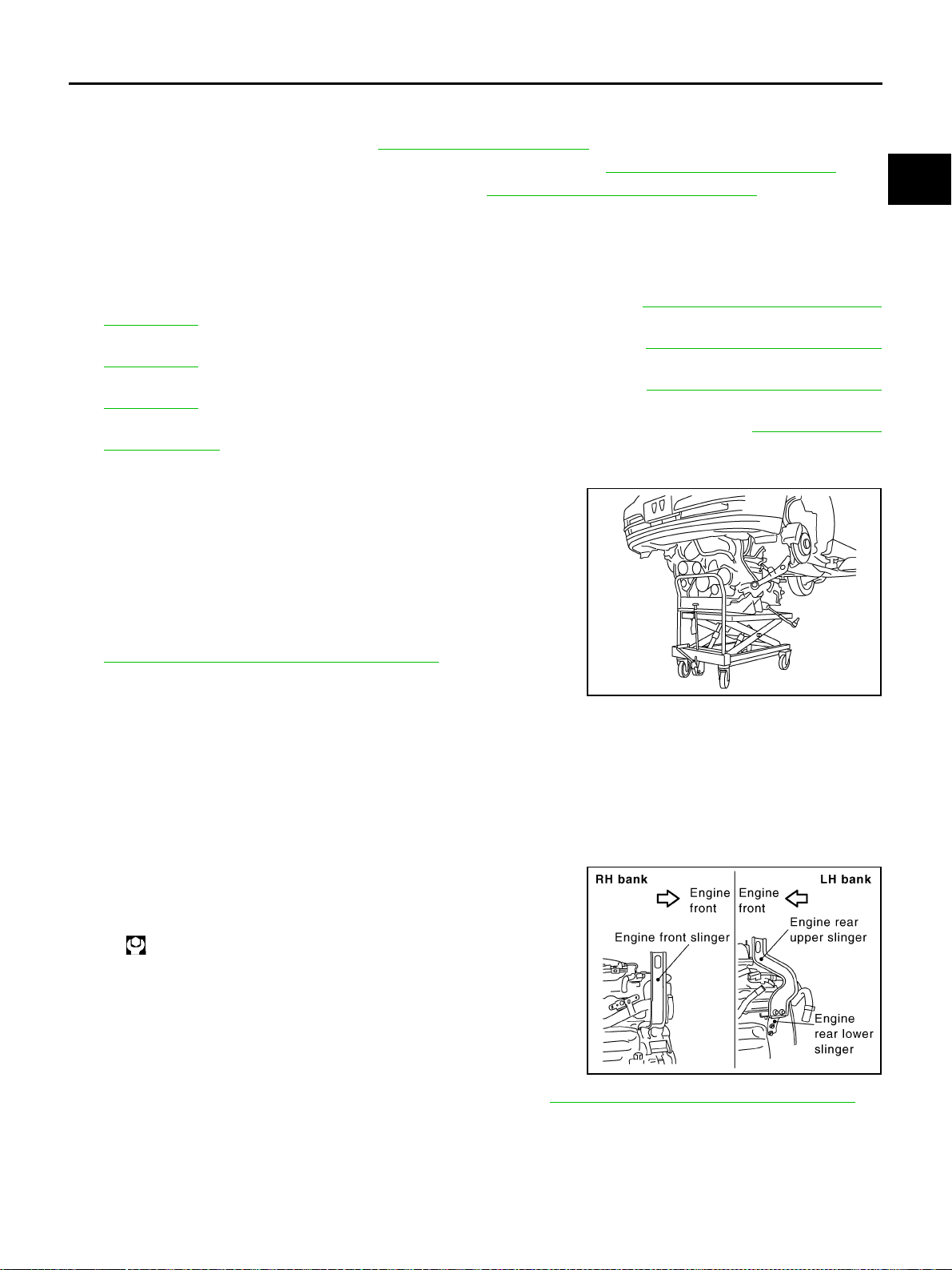
1. Use a manual lift table caddy (commercial service tool) or equiv-
alently rigid tool such as a transmission jack. Securely support
bottom of suspension member and transmission.
CAUTION:
Put a piece of wood or something similar as the supporting
surface, secure a completely stable condition.
2. Remove rear member mounting bolt.
3. Remove suspension member mounting bolt and nut. Refer to
FSU-6, "
FRONT SUSPENSION ASSEMBLY" .
4. Carefully lower jack to remove engine, transmission, and sus-
pension member assembly. When performing work, observe the
following:
CAUTION:
● Confirm there is no interference with vehicle.
● Make sure all connection points have been disconnected.
● Keep in mind the center of vehicle gravity changes. If necessary, use jack(s) to support vehicle
at rear jacking point(s) to prevent it from falling it off lift.
Separation Work
1. Install engine slingers into front of RH bank cylinder head and
rear of left bank cylinder head.
2. Remove power steering oil pump from engine side. Refer to PS-31, "
POWER STEERING OIL PUMP" .
3. Remove engine mounting insulator RR under side nut with power tool.
4. Lift with hoist and separate engine and transmission assembly from suspension member.
CAUTION:
● Before and during this lifting, always check if any harnesses are left connected.
● Avoid damage to and oil/grease smearing or spills onto engine mounting insulator.
PBIC0804E
Slinger bolts:
: 28.0 N·m (2.9 kg-m, 21 ft-lb)
SBIA0474E
Loading ...
Loading ...
Loading ...