Loading ...
Loading ...
Loading ...
EM-198
[VK45DE]
TIMING CHAIN
Revision: 2004 November 2004 FX35/FX45
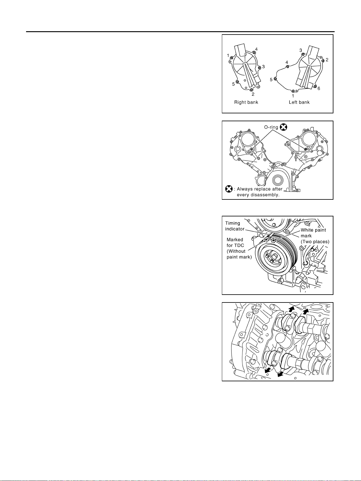
5. Remove intake valve timing control cover as follows:
a. Loosen and remove mounting bolts in the reverse order as
shown in the figure.
b. Use seal cutter [SST: KV10111100 (J37228)] or equivalent tool
to cut liquid gasket for removal.
CAUTION:
● Exercise care not to damage mating surfaces.
● Pull out cover keeping levelness without an angle, as
inner part of cover is engaged with the center of camshaft
sprocket (INT).
6. Remove O-rings from front cover.
7. Obtain No. 1 cylinder at TDC of its compression stroke as follows:
a. Rotate crankshaft pulley clockwise to align the TDC identifica-
tion notch (without paint mark) with timing indicator on front
cover.
b. Make sure that both intake and exhaust cam noses of No. 1 cyl-
inder (engine front side of left bank) are located as shown in the
figure.
● If not, turn crankshaft pulley one revolution (360 degrees) and
align as shown in the figure.
8. Remove crankshaft pulley as follows:
PBIC0051E
SBIA0374E
PBIC2341E
KBIA0400J
Loading ...
Loading ...
Loading ...