Loading ...
Loading ...
Loading ...
EM-236
[VK45DE]
ENGINE ASSEMBLY
Revision: 2004 November 2004 FX35/FX45
ENGINE ASSEMBLY PFP:10001
Removal and Installation ABS006IT
WARNING:
● Situate vehicle on a flat and solid surface.
● Place chocks at front and back of rear wheels.
● For engines not equipped with engine slingers, attach proper slingers and bolts described in
PARTS CATALOG.
CAUTION:
● Always be careful to work safely, avoid forceful or uninstructed operations.
● Do not start working until exhaust system and engine coolant are cool enough.
● If items or work required are not covered by the engine section, refer to the applicable sections.
● Always use the support point specified for lifting.
● Use either 2-point lift type or separate type lift as best you can. If board-on type is used for
unavoidable reasons, support at the rear axle jacking point with transmission jack or similar tool
before starting work, in preparation for the backward shift of center of gravity.
● For supporting points for lifting and jacking point at rear axle, refer to GI-42, "Garage Jack and
Safety Stand" .
REMOVAL
Outline
At first, remove engine, transmission assembly and front final drive with front suspension member downward.
Then separate engine from transmission.
Preparation
1. Release fuel pressure. Refer to EC-700, "FUEL PRESSURE RELEASE" .
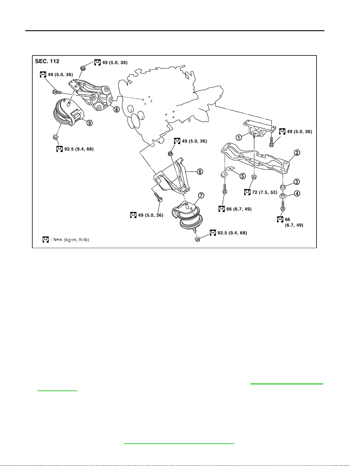
1. Engine mounting insulator (rear) 2. Engine rear member 3. Grommet
4. Collar 5. Plate 6. Engine mounting bracket (LH)
7. Engine mounting insulator (LH) 8. Engine mounting bracket (RH) 9. Engine mounting insulator (RH)
PBIC2364E
Loading ...
Loading ...
Loading ...