Loading ...
Loading ...
Loading ...
EM-216
[VK45DE]
CAMSHAFT
Revision: 2004 November 2004 FX35/FX45
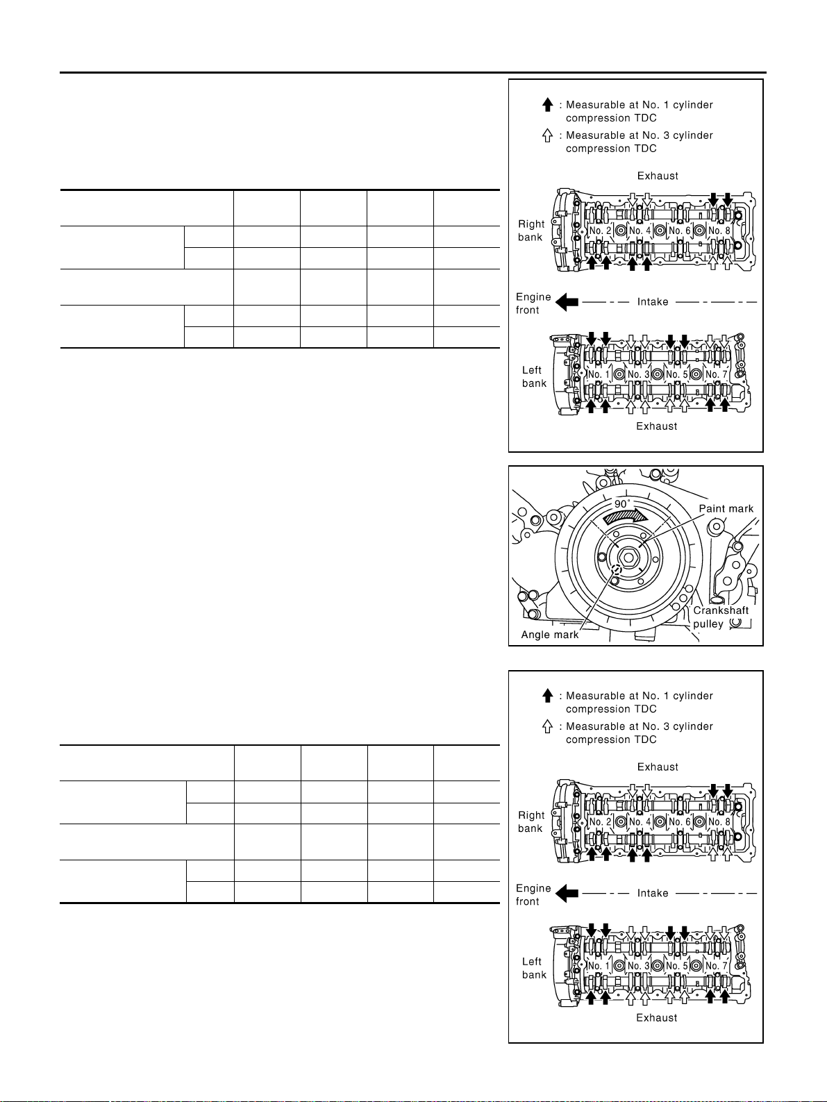
● By referring to the figure, measure valve clearances at loca-
tions marked “×” as shown in the table below (locations indi-
cated with black arrow in figure).
NOTE:
Firing order 1-8-7-3-6-5-4-2
● No.1 cylinder compression TDC
c. Rotate crankshaft pulley clockwise (when view from engine
front) by 270 degrees from the position of No. 1 cylinder com-
pression TDC to align No. 3 cylinder at TDC of its compression
stroke.
NOTE:
Crankshaft pulley mounting bolt flange has a angle mark every
90 degrees. They can be used as a guide to rotation angle.
● By referring to the figure, measure valve clearances at loca-
tions marked “×” as shown in the table below (locations indi-
cated with white arrow in figure)
● No.3 cylinder compression TDC
Measuring position (right bank)
No. 2
CYL.
No. 4
CYL.
No. 6
CYL.
No. 8
CYL.
No. 1 cylinder at TDC
EXH ×
INT ××
Measuring position (left bank)
No. 1
CYL.
No. 3
CYL.
No. 5
CYL.
No. 7
CYL.
No. 1 cylinder at TDC
INT ××
EXH ××
PBIC2358E
PBIC2346E
Measuring position (right bank)
No. 2
CYL.
No. 4
CYL.
No. 6
CYL.
No. 8
CYL.
No. 3 cylinder at TDC
EXH ×
INT ×
Measuring position (left bank)
No. 1
CYL.
No. 3
CYL.
No. 5
CYL.
No. 7
CYL.
No. 3 cylinder at TDC
INT ××
EXH ××
PBIC2358E
Loading ...
Loading ...
Loading ...