EM-1
ENGINE MECHANICAL
B ENGINE
CONTENTS
C
D
E
F
G
H
I
J
K
L
M
SECTION EM
A
EM
Revision: 2004 November 2004 FX35/FX45
ENGINE MECHANICAL
VQ35DE
PRECAUTIONS .......................................................... 5
Precautions Necessary for Steering Wheel Rotation
After Battery Disconnect .......................................... 5
OPERATION PROCEDURE ................................. 5
Precautions for Drain Engine Coolant ...................... 5
Precautions for Disconnecting Fuel Piping .............. 5
Precautions for Removal and Disassembly ............. 5
Precautions for Inspection, Repair and Replace-
ment ......................................................................... 5
Precautions for Assembly and Installation ............... 5
Parts Requiring Angle Tightening ............................. 6
Precautions for Liquid Gasket .................................. 6
REMOVAL OF LIQUID GASKET SEALING .......... 6
LIQUID GASKET APPLICATION PROCEDURE ..... 6
PREPARATION ........................................................... 8
Special Service Tools ............................................... 8
Commercial Service Tools ...................................... 10
NOISE, VIBRATION AND HARSHNESS (NVH)
TROUBLESHOOTING .............................................. 13
NVH Troubleshooting —Engine Noise ................... 13
Use the Chart Below to Help You Find the Cause
of the Symptom. ..................................................... 14
DRIVE BELTS ........................................................... 15
Checking Drive Belts .............................................. 15
Tension Adjustment ................................................ 15
ALTERNATOR AND POWER STEERING OIL
PUMP BELT ........................................................ 16
AIR CONDITIONER COMPRESSOR BELT ....... 16
Removal and Installation ........................................ 16
REMOVAL ........................................................... 16
INSTALLATION ................................................... 16
AIR CLEANER AND AIR DUCT ............................... 17
Removal and Installation ........................................ 17
REMOVAL ........................................................... 17
INSTALLATION ................................................... 17
Changing Air Cleaner Filter .................................... 18
INSPECTION ...................................................... 18
REMOVAL ........................................................... 18
INSTALLATION ................................................... 18
INTAKE MANIFOLD COLLECTOR ..........................19
Removal and Installation ........................................19
REMOVAL ...........................................................19
INSPECTION AFTER REMOVAL .......................21
INSTALLATION ...................................................22
INTAKE MANIFOLD .................................................24
Removal and Installation ........................................24
REMOVAL ...........................................................24
INSPECTION AFTER REMOVAL .......................24
INSTALLATION ...................................................25
EXHAUST MANIFOLD AND THREE WAY CATA-
LYST ..........................................................................26
Removal and Installation ........................................26
REMOVAL ...........................................................26
INSPECTION AFTER REMOVAL .......................28
INSTALLATION ...................................................28
OIL PAN AND OIL STRAINER .................................30
Removal and Installation ........................................30
2WD MODEL .......................................................30
REMOVAL ...........................................................30
INSPECTION AFTER REMOVAL .......................32
INSTALLATION ...................................................32
INSPECTION AFTER INSTALLATION ................35
AWD MODEL ......................................................36
REMOVAL ...........................................................36
INSPECTION AFTER REMOVAL .......................38
INSTALLATION ...................................................39
INSPECTION AFTER INSTALLATION ................41
IGNITION COIL .........................................................42
Removal and Installation ........................................42
REMOVAL ...........................................................42
INSTALLATION ...................................................42
SPARK PLUG (PLATINUM-TIPPED TYPE) .............43
Removal and Installation ........................................43
REMOVAL ...........................................................43
INSPECTION AFTER REMOVAL .......................43
INSTALLATION ...................................................44

EM-2
Revision: 2004 November 2004 FX35/FX45
FUEL INJECTOR AND FUEL TUBE ........................45
Removal and Installation ........................................45
REMOVAL ...........................................................46
INSTALLATION ....................................................47
INSPECTION AFTER INSTALLATION ................49
ROCKER COVER .....................................................51
Removal and Installation ........................................51
REMOVAL ...........................................................51
INSTALLATION ....................................................52
FRONT TIMING CHAIN CASE .................................54
Removal and Installation ........................................54
REMOVAL ...........................................................54
INSTALLATION ....................................................58
INSPECTION AFTER INSTALLATION ................62
TIMING CHAIN ..........................................................63
Removal and Installation ........................................63
REMOVAL ...........................................................64
INSPECTION AFTER REMOVAL ........................71
INSTALLATION ....................................................71
INSPECTION AFTER INSTALLATION ................80
CAMSHAFT ...............................................................82
Removal and Installation ........................................82
REMOVAL ...........................................................83
INSPECTION AFTER REMOVAL ........................84
INSTALLATION ....................................................87
Valve Clearance ......................................................89
INSPECTION .......................................................89
ADJUSTMENT ....................................................92
OIL SEAL ..................................................................94
Removal and Installation of Valve Oil Seal .............94
REMOVAL ...........................................................94
INSTALLATION ....................................................94
Removal and Installation of Front Oil Seal .............95
REMOVAL ...........................................................95
INSTALLATION ....................................................96
Removal and Installation of Rear Oil Seal ..............96
REMOVAL ...........................................................96
INSTALLATION ....................................................96
CYLINDER HEAD .....................................................98
On-Vehicle Service .................................................98
CHECKING COMPRESSION PRESSURE .........98
Removal and Installation ........................................99
REMOVAL ...........................................................99
INSPECTION AFTER REMOVAL ......................100
INSTALLATION ..................................................101
Disassembly and Assembly ..................................102
DISASSEMBLY .................................................103
ASSEMBLY .......................................................103
Inspection After Disassembly ...............................104
VALVE DIMENSIONS ........................................104
VALVE GUIDE CLEARANCE ............................105
VALVE GUIDE REPLACEMENT .......................105
VALVE SEAT CONTACT ...................................107
VALVE SEAT REPLACEMENT .........................107
VALVE SPRING SQUARENESS .......................108
VALVE SPRING DIMENSIONS AND VALVE
SPRING PRESSURE LOAD ..............................109
ENGINE ASSEMBLY ...............................................110
Removal and Installation .......................................110
2WD MODEL .....................................................110
REMOVAL .......................................................... 111
INSTALLATION ..................................................113
INSPECTION AFTER INSTALLATION ..............113
AWD MODEL .....................................................115
REMOVAL ..........................................................115
INSTALLATION ..................................................118
INSPECTION AFTER INSTALLATION ..............118
CYLINDER BLOCK .................................................120
Disassembly and Assembly ..................................120
DISASSEMBLY ..................................................121
ASSEMBLY ........................................................126
How to Select Piston and Bearing ........................131
DESCRIPTION ..................................................131
HOW TO SELECT PISTON ...............................131
HOW TO SELECT CONNECTING ROD BEAR-
ING .....................................................................132
HOW TO SELECT MAIN BEARING ..................133
Inspection After Disassembly ................................136
CRANKSHAFT END PLAY ................................136
CONNECTING ROD SIDE CLEARANCE .........136
PISTON TO PISTON PIN OIL CLEARANCE .....136
PISTON RING SIDE CLEARANCE ...................137
PISTON RING END GAP ..................................137
CONNECTING ROD BEND AND TORSION .....138
CONNECTING ROD BEARING HOUSING
DIAMETER (BIG END) ......................................138
CONNECTING ROD BUSHING OIL CLEAR-
ANCE (SMALL END) .........................................138
CYLINDER BLOCK DISTORTION ....................139
MAIN BEARING HOUSING INNER DIAMETER .140
PISTON TO CYLINDER BORE CLEARANCE ..140
CRANKSHAFT MAIN JOURNAL DIAMETER ...141
CRANKSHAFT PIN JOURNAL DIAMETER ......142
CRANKSHAFT OUT-OF-ROUND AND TAPER .142
CRANKSHAFT RUNOUT ..................................142
CONNECTING ROD BEARING OIL CLEAR-
ANCE .................................................................142
MAIN BEARING OIL CLEARANCE ...................143
MAIN BEARING CRUSH HEIGHT ....................144
CONNECTING ROD BEARING CRUSH
HEIGHT .............................................................144
MAIN BEARING CAP BOLT OUTER DIAMETER .144
CONNECTING ROD BOLT OUTER DIAMETER .144
DRIVE PLATE ....................................................145
OIL JET ..............................................................145
OIL JET RELIEF VALVE ....................................145
SERVICE DATA AND SPECIFICATIONS (SDS) ....146
Standard and Limit ................................................146
GENERAL SPECIFICATIONS ...........................146
DRIVE BELT ......................................................147
INTAKE MANIFOLD COLLECTOR, INTAKE

EM-3
C
D
E
F
G
H
I
J
K
L
M
EM
A
Revision: 2004 November 2004 FX35/FX45
MANIFOLD AND EXHAUST MANIFOLD ......... 147
SPARK PLUG ................................................... 147
CAMSHAFT AND CAMSHAFT BEARING ........ 148
CYLINDER HEAD ............................................. 150
CYLINDER BLOCK ........................................... 153
PISTON, PISTON RING AND PISTON PIN ...... 154
CONNECTING ROD ......................................... 155
CRANKSHAFT .................................................. 156
MAIN BEARING ................................................ 157
CONNECTING ROD BEARING ........................ 158
VK45DE
PRECAUTIONS ...................................................... 159
Precautions Necessary for Steering Wheel Rotation
After Battery Disconnect ...................................... 159
OPERATION PROCEDURE ............................. 159
Precautions for Drain Engine Coolant .................. 159
Precautions for Disconnecting Fuel Piping .......... 159
Precautions for Removal and Disassembly ......... 159
Precautions for Inspection, Repair and Replace-
ment ..................................................................... 159
Precautions for Assembly and Installation ........... 159
Parts Requiring Angle Tightening ......................... 160
Precautions for Liquid Gasket .............................. 160
REMOVAL OF LIQUID GASKET SEALING ...... 160
LIQUID GASKET APPLICATION PROCEDURE . 160
PREPARATION ....................................................... 162
Special Service Tools ........................................... 162
Commercial Service Tools .................................... 164
NOISE, VIBRATION AND HARSHNESS (NVH)
TROUBLESHOOTING ............................................ 166
NVH Troubleshooting —Engine Noise ................. 166
Use the Chart Below to Help You Find the Cause
of the Symptom. ................................................... 167
ENGINE ROOM COVER ........................................ 168
Removal and Installation ...................................... 168
REMOVAL ......................................................... 168
INSTALLATION ................................................. 168
DRIVE BELTS ......................................................... 169
Checking Drive Belts ............................................ 169
Tension Adjustment .............................................. 169
Removal and Installation ...................................... 169
REMOVAL ......................................................... 169
INSTALLATION ................................................. 170
Drive Belt Auto Tensioner and Idler Pulley ........... 171
REMOVAL ......................................................... 171
INSTALLATION ................................................. 171
AIR CLEANER AND AIR DUCT ............................. 172
Removal and Installation ...................................... 172
REMOVAL ......................................................... 172
INSTALLATION ................................................. 172
Changing Air Cleaner Filter .................................. 173
REMOVAL ......................................................... 173
INSTALLATION ................................................. 173
INTAKE MANIFOLD ...............................................174
Removal and Installation ......................................174
REMOVAL .........................................................174
INSPECTION AFTER REMOVAL .....................176
INSTALLATION .................................................176
INSPECTION AFTER INSTALLATION ..............177
EXHAUST MANIFOLD AND THREE WAY CATA-
LYST ........................................................................178
Removal and Installation ......................................178
REMOVAL .........................................................178
INSPECTION AFTER REMOVAL .....................180
INSTALLATION .................................................180
OIL PAN AND OIL STRAINER ...............................181
Removal and Installation ......................................181
REMOVAL .........................................................181
INSPECTION AFTER REMOVAL .....................183
INSTALLATION .................................................183
INSPECTION AFTER INSTALLATION ..............183
IGNITION COIL .......................................................185
Removal and Installation ......................................185
REMOVAL .........................................................185
INSTALLATION .................................................185
SPARK PLUG (PLATINUM-TIPPED TYPE) ...........186
Removal and Installation ......................................186
REMOVAL .........................................................186
INSPECTION AFTER REMOVAL .....................186
INSTALLATION .................................................187
FUEL INJECTOR AND FUEL TUBE ......................188
Removal and Installation ......................................188
REMOVAL .........................................................188
INSTALLATION .................................................190
INSPECTION AFTER INSTALLATION ..............192
ROCKER COVER ...................................................193
Removal and Installation ......................................193
REMOVAL .........................................................193
INSTALLATION .................................................195
TIMING CHAIN ........................................................196
Removal and Installation ......................................196
REMOVAL .........................................................197
INSPECTION AFTER REMOVAL .....................201
INSTALLATION .................................................201
INSPECTION AFTER INSTALLATION ..............207
CAMSHAFT ............................................................208
Removal and Installation ......................................208
REMOVAL .........................................................208
INSPECTION AFTER REMOVAL .....................209
INSTALLATION .................................................212
Valve Clearance ...................................................214
INSPECTION ....................................................214
ADJUSTMENT ..................................................217
OIL SEAL ................................................................221
Removal and Installation of Valve Oil Seal ...........221
REMOVAL .........................................................221
INSTALLATION .................................................221
Removal and Installation of Front Oil Seal ...........222
REMOVAL .........................................................222

EM-4
Revision: 2004 November 2004 FX35/FX45
INSTALLATION ..................................................222
Removal and Installation of Rear Oil Seal ............223
REMOVAL .........................................................223
INSTALLATION ..................................................223
CYLINDER HEAD ...................................................224
On-Vehicle Service ...............................................224
CHECKING COMPRESSION PRESSURE .......224
Removal and Installation ......................................225
REMOVAL .........................................................225
INSPECTION AFTER REMOVAL ......................226
INSTALLATION ..................................................226
Disassembly and Assembly ..................................228
DISASSEMBLY .................................................228
ASSEMBLY .......................................................229
Inspection After Disassembly ...............................230
VALVE DIMENSIONS ........................................230
VALVE GUIDE CLEARANCE ............................231
VALVE GUIDE REPLACEMENT .......................231
VALVE SEAT CONTACT ...................................232
VALVE SEAT REPLACEMENT .........................233
VALVE SPRING SQUARENESS .......................234
VALVE SPRING DIMENSIONS AND VALVE
SPRING PRESSURE LOAD .............................235
ENGINE ASSEMBLY ..............................................236
Removal and Installation ......................................236
REMOVAL .........................................................236
INSTALLATION ..................................................239
INSPECTION AFTER INSTALLATION ..............239
CYLINDER BLOCK .................................................240
Disassembly and Assembly ..................................240
DISASSEMBLY .................................................241
ASSEMBLY .......................................................244
How to Select Piston and Bearing ........................250
DESCRIPTION ..................................................250
HOW TO SELECT PISTON ...............................250
HOW TO SELECT CONNECTING ROD BEAR-
ING ....................................................................251
HOW TO SELECT MAIN BEARING ..................252
Inspection After Disassembly ................................256
CRANKSHAFT END PLAY ................................256
CONNECTING ROD SIDE CLEARANCE .........256
PISTON TO PISTON PIN OIL CLEARANCE .....256
PISTON RING SIDE CLEARANCE ...................257
PISTON RING END GAP ..................................257
CONNECTING ROD BEND AND TORSION .....258
CONNECTING ROD BIG END DIAMETER ......258
CONNECTING ROD BUSHING OIL CLEAR-
ANCE .................................................................258
CYLINDER BLOCK DISTORTION ....................259
MAIN BEARING HOUSING INNER DIAMETER .260
PISTON TO CYLINDER BORE CLEARANCE ..260
CRANKSHAFT MAIN JOURNAL DIAMETER ...261
CRANKSHAFT PIN JOURNAL DIAMETER ......262
CRANKSHAFT OUT-OF-ROUND AND TAPER .262
CRANKSHAFT RUNOUT ..................................262
CONNECTING ROD BEARING OIL CLEAR-
ANCE .................................................................263
MAIN BEARING OIL CLEARANCE ...................264
CRUSH HEIGHT OF MAIN BEARING ..............265
CRUSH HEIGHT OF CONNECTING ROD
BEARING ...........................................................265
DRIVE PLATE ....................................................265
SERVICE DATA AND SPECIFICATIONS (SDS) ....266
Standard and Limit ................................................266
GENERAL SPECIFICATIONS ...........................266
DRIVE BELTS ....................................................266
INTAKE MANIFOLD AND EXHAUST MANI-
FOLD .................................................................266
SPARK PLUG ....................................................267
CAMSHAFT AND CAMSHAFT BEARING .........267
CYLINDER HEAD ..............................................269
CYLINDER BLOCK ............................................272
PISTON, PISTON RING AND PISTON PIN ......273
CONNECTING ROD ..........................................274
CRANKSHAFT ...................................................275
MAIN BEARING .................................................277
CONNECTING ROD BEARING .........................278

PRECAUTIONS
EM-5
[VQ35DE]
C
D
E
F
G
H
I
J
K
L
M
A
EM
Revision: 2004 November 2004 FX35/FX45
[VQ35DE]
PRECAUTIONS PFP:00001
Precautions Necessary for Steering Wheel Rotation After Battery Disconnect
ABS00B3I
NOTE:
● This Procedure is applied only to models with Intelligent Key system and NVIS/IVIS (NISSAN/INFINITI
VEHICLE IMMOBILIZER SYSTEM - NATS).
● Remove and install all control units after disconnecting both battery cables with the ignition knob in the
″LOCK″ position.
● Always use CONSULT-II to perform self-diagnosis as a part of each function inspection after finishing
work. If DTC is detected, perform trouble diagnosis according to self-diagnostic results.
For models equipped with the Intelligent Key system and NVIS/IVIS, an electrically controlled steering lock
mechanism is adopted on the key cylinder.
For this reason, if the battery is disconnected or if the battery is discharged, the steering wheel will lock and
steering wheel rotation will become impossible.
If steering wheel rotation is required when battery power is interrupted, follow the procedure below before
starting the repair operation.
OPERATION PROCEDURE
1. Connect both battery cables.
NOTE:
Supply power using jumper cables if battery is discharged.
2. Use the Intelligent Key or mechanical key to turn the ignition switch to the ″ACC″ position. At this time, the
steering lock will be released.
3. Disconnect both battery cables. The steering lock will remain released and the steering wheel can be
rotated.
4. Perform the necessary repair operation.
5. When the repair work is completed, return the ignition switch to the ″LOCK″ position before connecting
the battery cables. (At this time, the steering lock mechanism will engage.)
6. Perform a self-diagnosis check of all control units using CONSULT-II.
Precautions for Drain Engine Coolant ABS005ZK
Drain engine coolant when engine is cooled.
Precautions for Disconnecting Fuel Piping ABS005ZL
● Before starting work, make sure no fire or spark producing items are in the work area.
● Release fuel pressure before disconnecting and disassembly.
● After disconnecting pipes, plug openings to stop fuel leakage.
Precautions for Removal and Disassembly ABS005ZM
● When instructed to use special service tools, use the specified tools. Always be careful to work safely,
avoid forceful or uninstructed operations.
● Exercise maximum care to avoid damage to mating or sliding surfaces.
● Cover openings of engine system with tape or the equivalent, if necessary, to seal out foreign materials.
● Mark and arrange disassembly parts in an organized way for easy troubleshooting and re-assembly.
● When loosening nuts and bolts, as a basic rule, start with the one furthest outside, then the one diagonally
opposite, and so on. If the order of loosening is specified, do exactly as specified. Power tools may be
used where noted in the step.
Precautions for Inspection, Repair and Replacement ABS005ZN
Before repairing or replacing, thoroughly inspect parts. Inspect new replacement parts in the same way, and
replace if necessary.
Precautions for Assembly and Installation ABS005ZO
● Use torque wrench to tighten bolts or nuts to specification.
EM-6
[VQ35DE]
PRECAUTIONS
Revision: 2004 November 2004 FX35/FX45
● When tightening nuts and bolts, as a basic rule, equally tighten in several different steps starting with the
ones in center, then ones on inside and outside diagonally in this order. If the order of tightening is speci-
fied, do exactly as specified.
● Replace with new liquid gasket, packing, oil seal or O-ring.
● Thoroughly wash, clean, and air-blow each part. Carefully check engine oil or engine coolant passages for
any restriction and blockage.
● Avoid damaging sliding or mating surfaces. Completely remove foreign materials such as cloth lint or dust.
Before assembly, oil sliding surfaces well.
● Release air within route when refilling after draining engine coolant.
● Before starting engine, apply fuel pressure to fuel lines with turning ignition switch “ON” (with engine
stopped). Then make sure that there are no leaks at fuel line connections.
● After repairing, start engine and increase engine speed to check engine coolant, fuel, engine oil and
exhaust systems for leakage.
Parts Requiring Angle Tightening ABS005ZP
● Use an angle wrench [SST: KV10112100 (BT8653-A)] for the final tightening of the following engine parts:
– Cylinder head bolts
– Main bearing cap bolts
– Connecting rod cap bolts
– Crankshaft pulley bolt (No angle wrench is required as the bolt flange is provided with notches for angle
tightening)
● Do not use a torque value for final tightening.
● The torque value for these parts are for a preliminary step.
● Ensure thread and seat surfaces are clean and coated with engine oil.
Precautions for Liquid Gasket ABS005ZQ
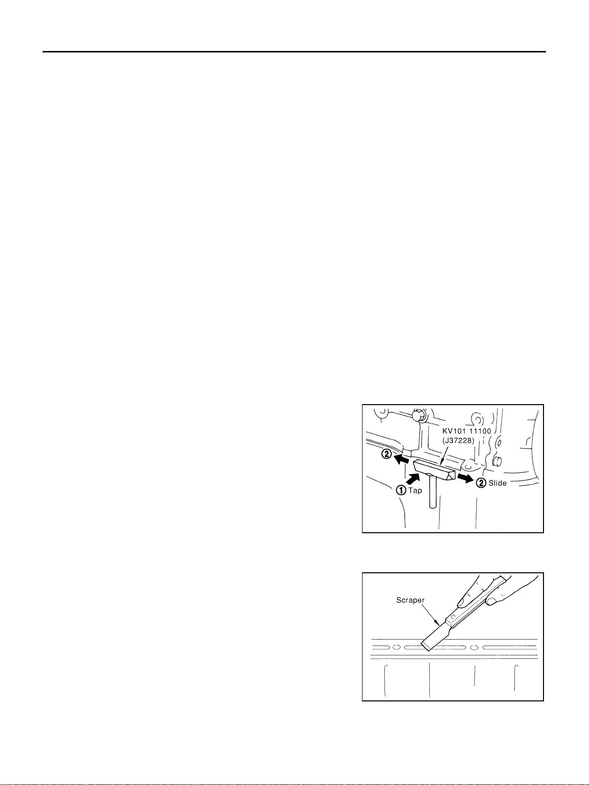
REMOVAL OF LIQUID GASKET SEALING
● After removing mounting bolts and nuts, separate the mating
surface using a seal cutter (SST) and remove old liquid gasket
sealing.
CAUTION:
Be careful not to damage the mating surfaces.
● Tap seal cutter to insert it, and then slide it by tapping on the
side as shown in the figure.
● In areas where seal cutter is difficult to use, use plastic hammer
to lightly tap the areas where the liquid gasket is applied.
CAUTION:
If for some unavoidable reason tool such as screwdriver is
used, be careful not to damage the mating surfaces.
LIQUID GASKET APPLICATION PROCEDURE
1. Using a scraper, remove old liquid gasket adhering to liquid gas-
ket application surface and the mating surface.
● Remove liquid gasket completely from the groove of the liquid
gasket application surface, mounting bolts, and bolt holes.
2. Wipe liquid gasket application surface and the mating surface
with white gasoline (lighting and heating use) to remove adher-
ing moisture, grease and foreign materials.
PBIC0002E
PBIC0003E
PRECAUTIONS
EM-7
[VQ35DE]
C
D
E
F
G
H
I
J
K
L
M
A
EM
Revision: 2004 November 2004 FX35/FX45
3. Attach liquid gasket tube to tube presser [SST: WS39930000 ( –
)].
Use Genuine RTV Silicone Sealant or equivalent. Refer to
GI-48, "
RECOMMENDED CHEMICAL PRODUCTS AND
SEALANTS" .
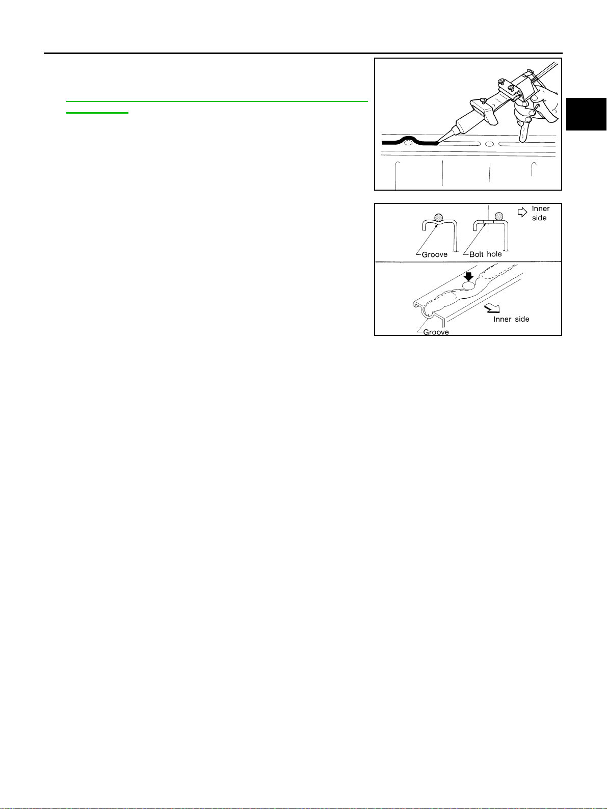
4. Apply liquid gasket without breaks to the specified location with
the specified dimensions.
● If there is a groove for the liquid gasket application, apply liq-
uid gasket to the groove.
● As for the bolt holes, normally apply liquid gasket inside the
holes. Occasionally, it should be applied outside the holes.
Make sure to read the text of service manual.
● Within five minutes of liquid gasket application, install the mat-
ing component.
● If liquid gasket protrudes, wipe it off immediately.
● Do not retighten mounting bolts and nuts after the installation.
● After 30 minutes or more have passed from the installation, fill
engine oil and engine coolant.
CAUTION:
If there are specific instructions in this manual, observe them.
EMA0622D
SEM159F
EM-8
[VQ35DE]
PREPARATION
Revision: 2004 November 2004 FX35/FX45
PREPARATION PFP:00002
Special Service Tools ABS004TT
The actual shapes of Kent-Moore tools may differ from those of special service tools illustrated here.
Tool number
(Kent-Moore No.)
Tool name
Description
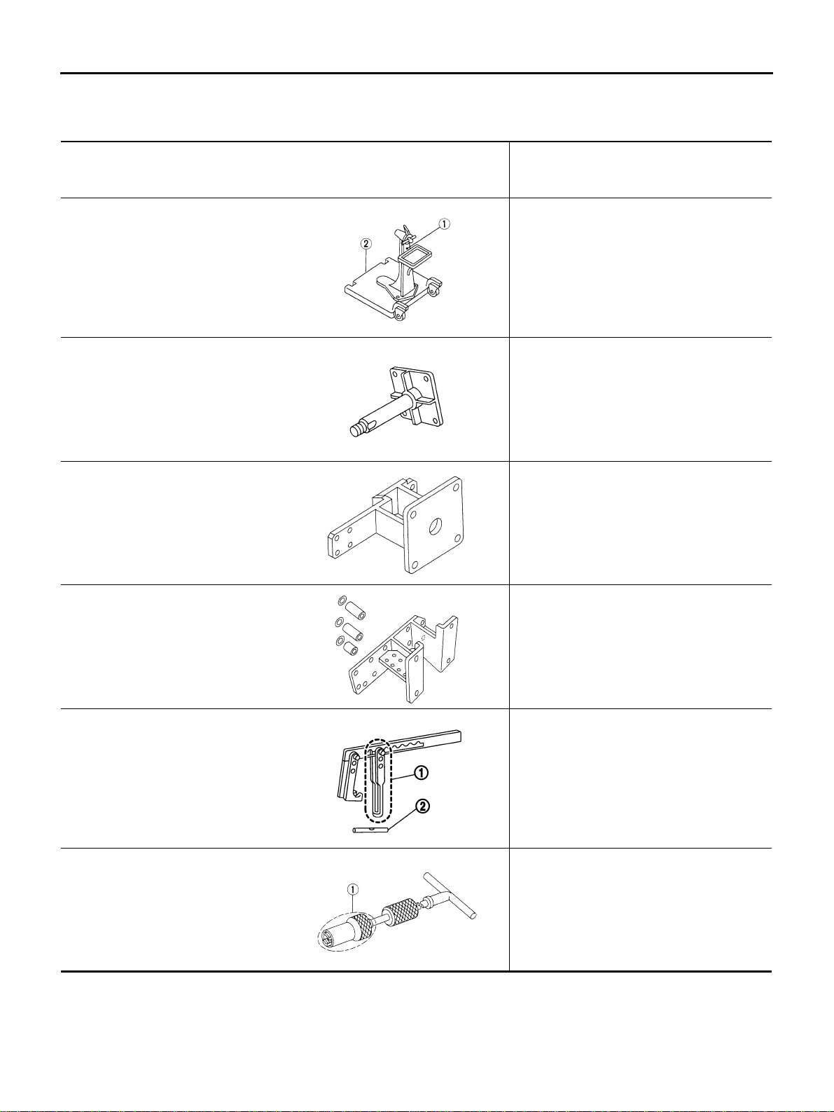
ST0501S000
(—)
Engine stand assembly
1. ST05011000
(—)
Engine stand
2. ST05012000
(—)
Base
Disassembling and assembling
KV10106500
(—)
Engine stand shaft
KV10117000
(J-41262)
Engine sub-attachment
KV10117000 has been replaced with
KV10117001 (KV10117000 is no longer in
production, but it is usable).
KV10117001
(—)
Engine sub-attachment
Installing on cylinder block
KV10116200
(J-26336-A)
Valve spring compressor
1. KV10115900
(J-26336-20)
Attachment
2. KV10109220
(—)
Adapter
Disassembling valve mechanism
Part (1) is a component of KV10116200
(J-26336-A), but Part (2) is not so.
KV10107902
(J-38959)
Valve oil seal puller
1. KV10116100
(—)
Valve oil seal puller adapter
Replacing valve oil seal
NT042
NT028
NT373
NT372
PBIC1650E
S-NT605
PREPARATION
EM-9
[VQ35DE]
C
D
E
F
G
H
I
J
K
L
M
A
EM
Revision: 2004 November 2004 FX35/FX45
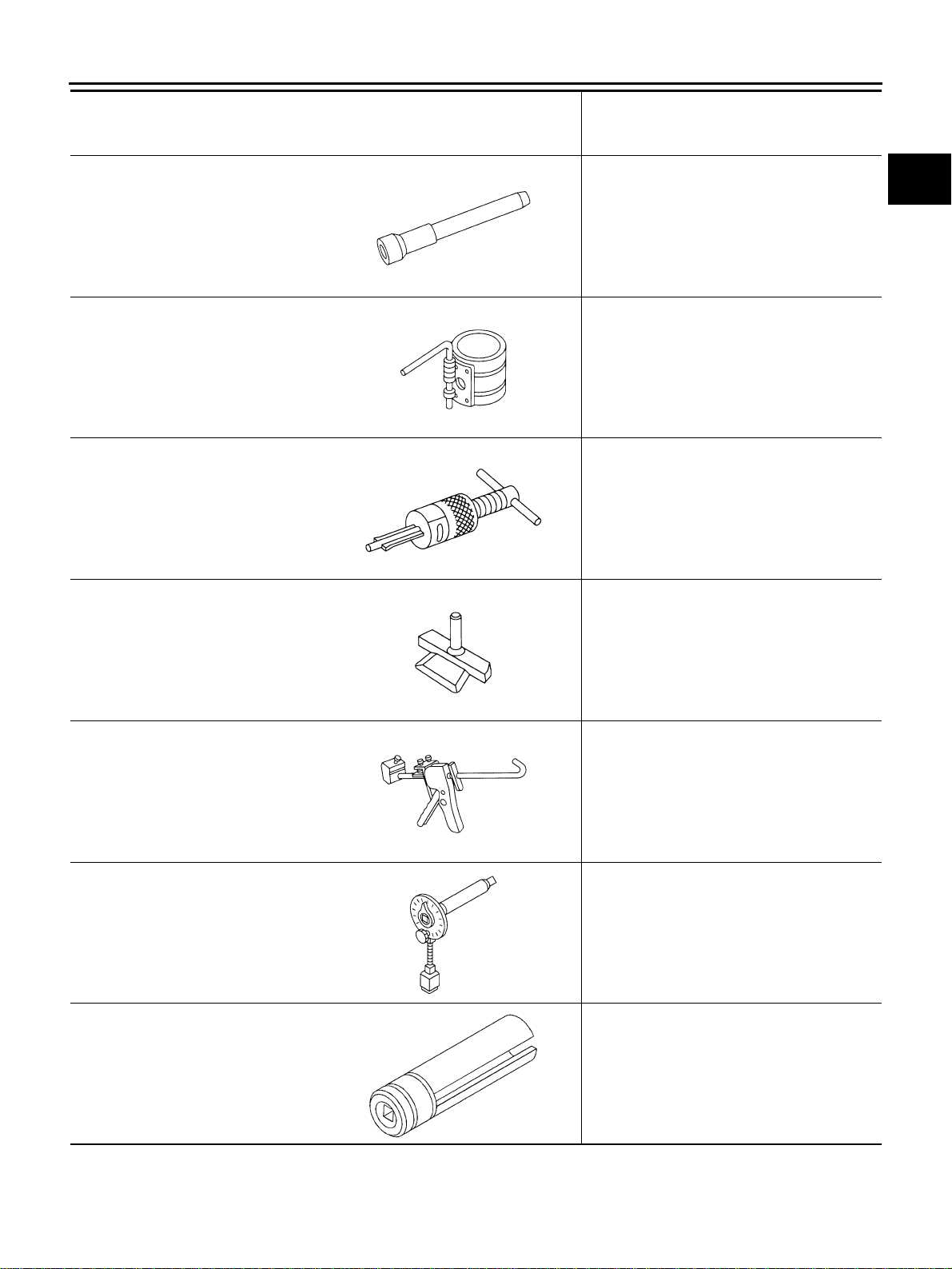
(J-39386)
Valve oil seal drift
Installing valve oil seal
EM03470000
(J-8037)
Piston ring compressor
Installing piston assembly into cylinder bore
ST16610001
(J-23907)
Pilot bushing puller
Removing crankshaft pilot converter
KV10111100
(J-37228)
Seal cutter
Removing steel oil pan (lower and upper) and
front and rear timing chain case
WS39930000
(—)
Tube presser
Pressing tube of liquid gasket
KV10112100
(BT8653-A)
Angle wrench
Tightening bolts for bearing cap, cylinder
head, etc. in angle
KV10117100
(J-3647-A)
Heated oxygen sensor wrench
Loosening or tightening heated oxygen
sensor 2
For 22 mm (0.87 in) width hexagon nut
Tool number
(Kent-Moore No.)
Tool name
Description
NT024
NT044
NT045
NT046
NT052
NT014
NT379
EM-10
[VQ35DE]
PREPARATION
Revision: 2004 November 2004 FX35/FX45
Commercial Service Tools ABS004TU
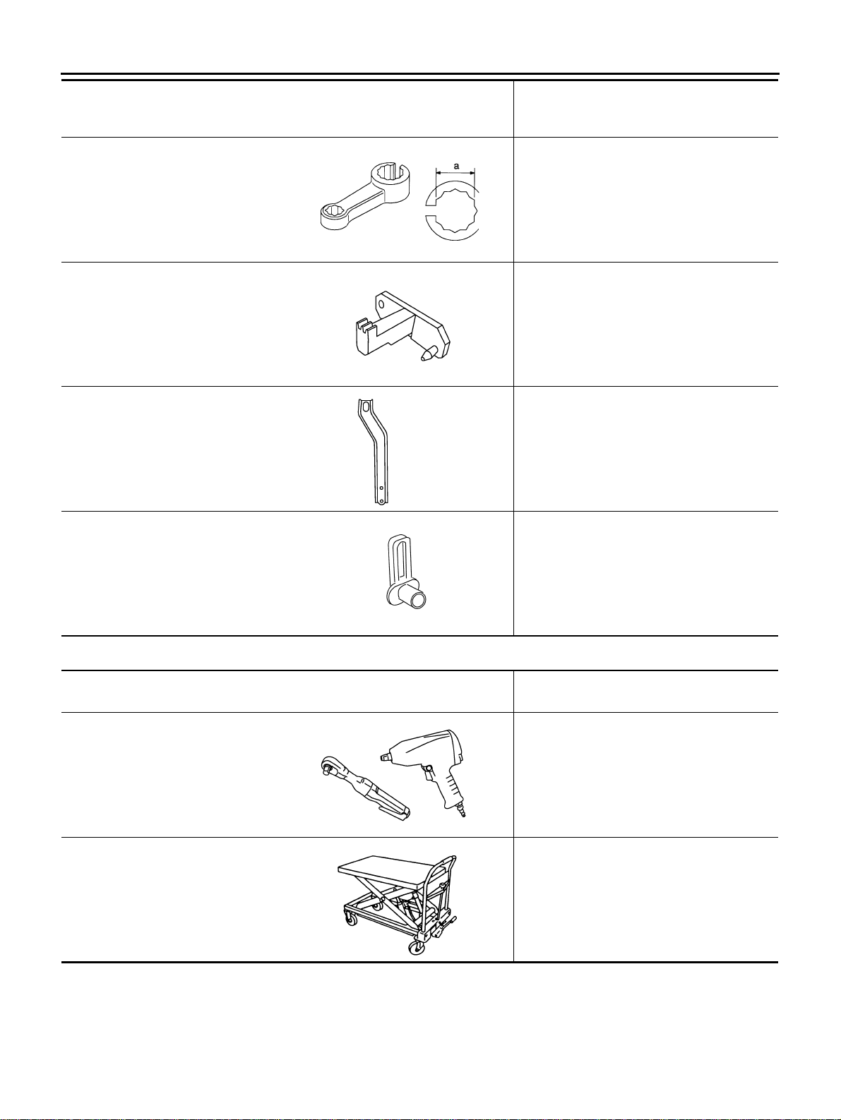
KV10114400
(J-38365)
Heated oxygen sensor wrench
Loosening or tightening heated oxygen
sensor
a: 22 mm (0.87 in)
KV10117700
(J-44716)
Ring gear stopper
Removing and installing crankshaft pulley
10006 31U00
(—)
Engine rear slinger
Removing and installing oil pan (upper) for on
vehicle service
—
(J-45488)
Quick connector release
Removing fuel tube quick connectors in
engine room (Right member side)
Tool number
(Kent-Moore No.)
Tool name
Description
NT636
NT822
SBIA0530E
PBIC0198E
(Kent-Moore No.)
Tool name
Description
Power tool Loosening bolts and nuts
Manual lift table caddy Removing and installing engine
PBIC0190E
ZZA1210D
PREPARATION
EM-11
[VQ35DE]
C
D
E
F
G
H
I
J
K
L
M
A
EM
Revision: 2004 November 2004 FX35/FX45
(BT3373-F)
Belt tension gauge
Checking drive belt tension
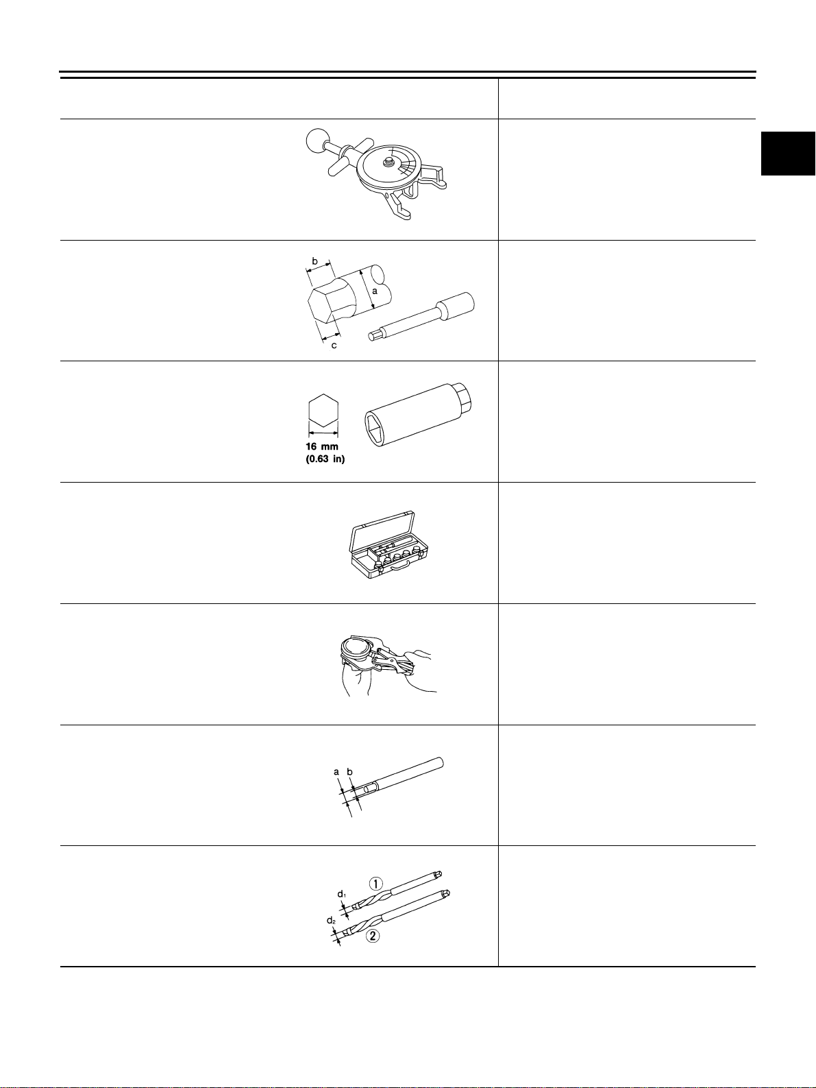
(J-24239-01)
Cylinder head bolt wrench
Loosening and tightening cylinder head bolt,
and used with angle wrench
[SST: KV10112100 (BT8653-A)]
a: 13 (0.51) dia.
b: 12 (0.47)
c: 10 (0.39)
Unit: mm (in)
Spark plug wrench Removing and installing spark plug
Valve seat cutter set Finishing valve seat dimensions
Piston ring expander Removing and installing piston ring
Valve guide drift Removing and installing valve guide
Intake & Exhaust
a: 9.5 mm (0.374 in) dia.
b: 5.5 mm (0.217 in) dia.
Valve guide reamer Reaming valve guide with (1) or hole for
oversize valve guide with (2)
Intake & Exhaust
d
1 : 6.0 mm (0.236 in) dia.
d
2: 10.2 mm (0.402 in) dia.
(Kent-Moore No.)
Tool name
Description
AMA126
NT583
NT047
NT048
NT030
NT015
NT016
EM-12
[VQ35DE]
PREPARATION
Revision: 2004 November 2004 FX35/FX45
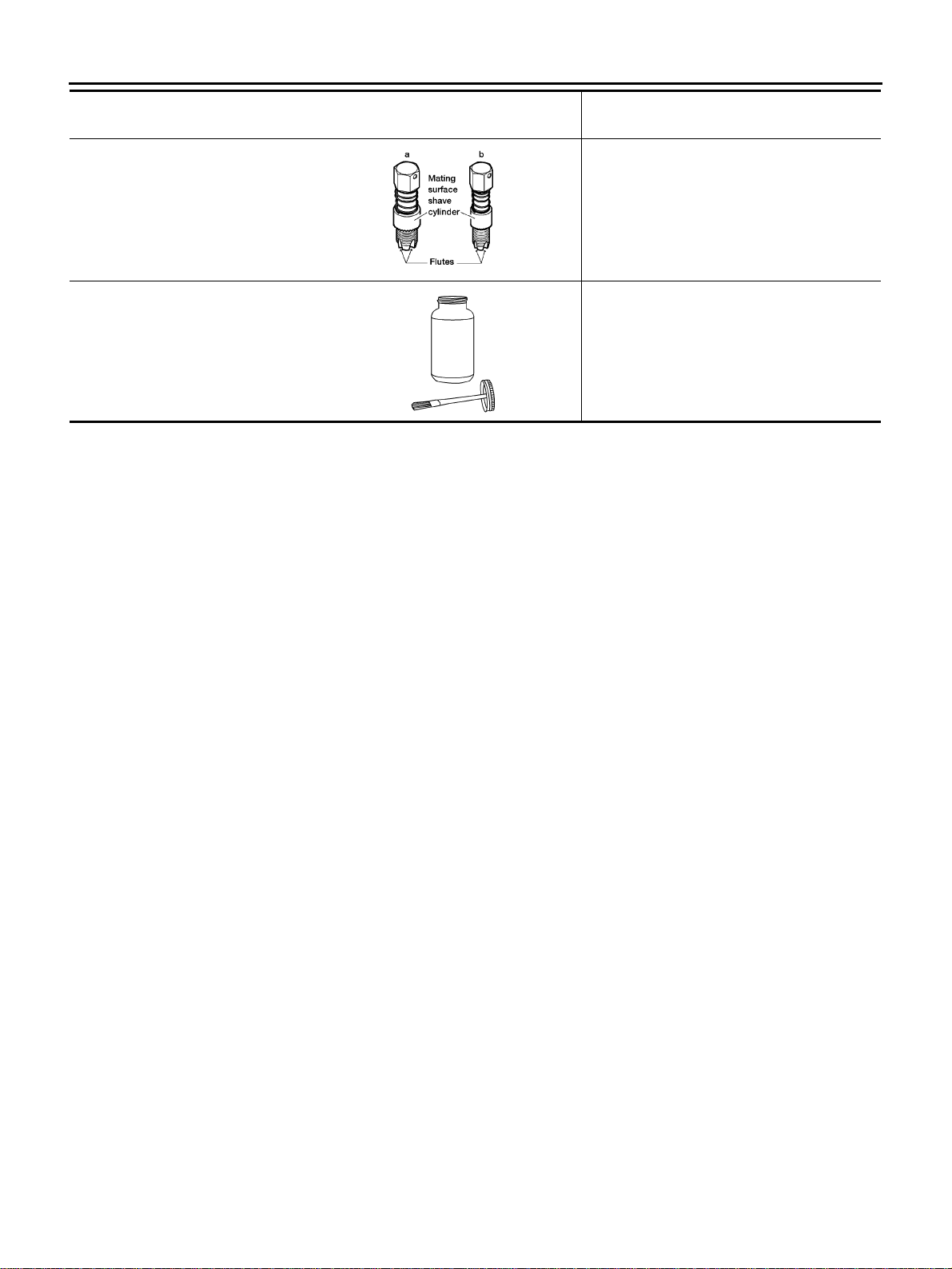
a: (J-43897-18)
b: (J-43897-12)
Oxygen sensor thread cleaner
Reconditioning the exhaust system threads
before installing a new heated oxygen
sensor (Use with anti-seize lubricant shown
below.)
a: J-43897-18 [18 mm (0.71 in) dia.] for
zirconia heated oxygen sensor
b: J-43897-12 [12 mm (0.47 in) dia.] for
titania heated oxygen sensor
Anti-seize lubricant (Permatex 133AR
or equivalent meeting MIL
specification MIL-A-907)
Lubricating heated oxygen sensor thread
cleaning tool when reconditioning exhaust
system threads
(Kent-Moore No.)
Tool name
Description
AEM488
AEM489

NOISE, VIBRATION AND HARSHNESS (NVH) TROUBLESHOOTING
EM-13
[VQ35DE]
C
D
E
F
G
H
I
J
K
L
M
A
EM
Revision: 2004 November 2004 FX35/FX45
NOISE, VIBRATION AND HARSHNESS (NVH) TROUBLESHOOTING PFP:00003
NVH Troubleshooting —Engine Noise ABS004TV
PBIC2039E
EM-14
[VQ35DE]
NOISE, VIBRATION AND HARSHNESS (NVH) TROUBLESHOOTING
Revision: 2004 November 2004 FX35/FX45
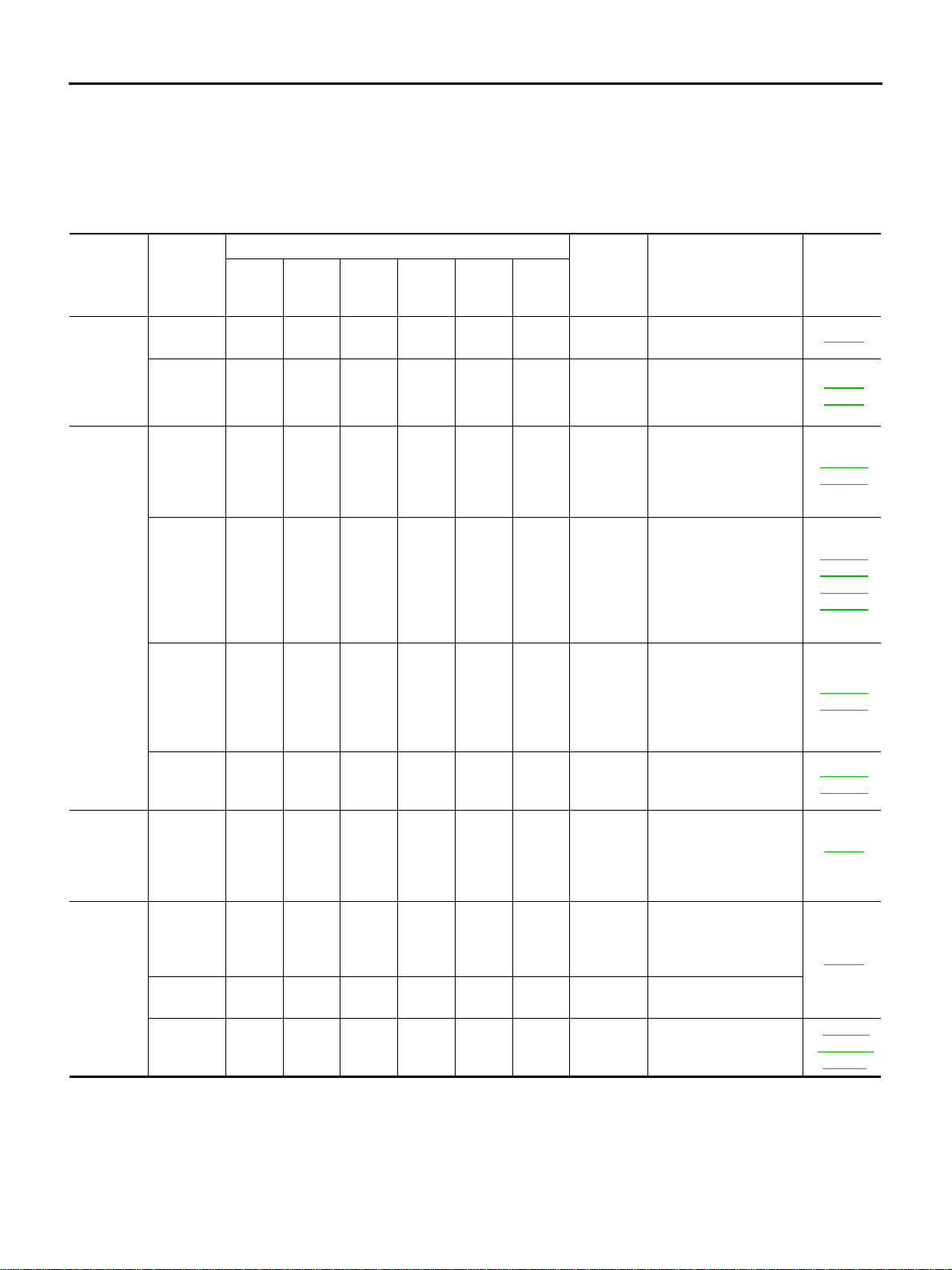
Use the Chart Below to Help You Find the Cause of the Symptom. ABS004TW
1. Locate the area where noise occurs.
2. Confirm the type of noise.
3. Specify the operating condition of engine.
4. Check specified noise source.
If necessary, repair or replace these parts.
A: Closely related B: Related C: Sometimes related —: Not related
Location
of noise
Type of
noise
Operating condition of engine
Source of
noise
Check item
Refer-
ence page
Before
warm-
up
After
warm-
up
When
start-
ing
When
idling
When
racing
While
driving
Top of
engine
Rocker
cover
Cylinder
head
Ticking or
clicking
CA—AB—
Tappet
noise
Valve clearance EM-89
Rattle C A — A B C
Camshaft
bearing
noise
Camshaft runout
Camshaft journal oil
clearance
EM-84
EM-84
Crank-
shaft pul-
ley
Cylinder
block
(Side of
engine)
Oil pan
Slap or
knock
—A—BB—
Piston pin
noise
Piston to piston pin oil
clearance
Connecting rod bush-
ing oil clearance (Small
end)
EM-136
EM-138
Slap or
rap
A——BBA
Piston
slap noise
Piston to cylinder bore
clearance
Piston ring side clear-
ance
Piston ring end gap
Connecting rod bend
and torsion
EM-140
EM-137
EM-137
EM-138
Knock A B C B B B
Connect-
ing rod
bearing
noise
Connecting rod bush-
ing oil clearance (Small
end)
Connecting rod bear-
ing housing diameter
(Big end)
EM-138
EM-138
Knock A B — A B C
Main
bearing
noise
Main bearing oil clear-
ance
Crankshaft runout
EM-143
EM-142
Front of
engine
Timing
chain
case
Tapping or
ticking
AA—BBB
Timing
chain and
chain ten-
sioner
noise
Timing chain cracks
and wear
Timing chain tensioner
operation
EM-71
Front of
engine
Squeak-
ing or fizz-
ing
AB—B—C
Drive belts
(Sticking
or slip-
ping)
Drive belts deflection
EM-15
CreakingABABAB
Drive belts
(Slipping)
Idler pulley bearing
operation
Squall
Creak
AB—BAB
Water
pump
noise
Water pump operation
CO-22,
"WATER
PUMP"
DRIVE BELTS
EM-15
[VQ35DE]
C
D
E
F
G
H
I
J
K
L
M
A
EM
Revision: 2004 November 2004 FX35/FX45
DRIVE BELTS PFP:02117
Checking Drive Belts ABS004TX
WARNING:
Be sure to perform when engine is stopped.
1. Inspect belts for cracks, fraying, wear and oil. If necessary,
replace.
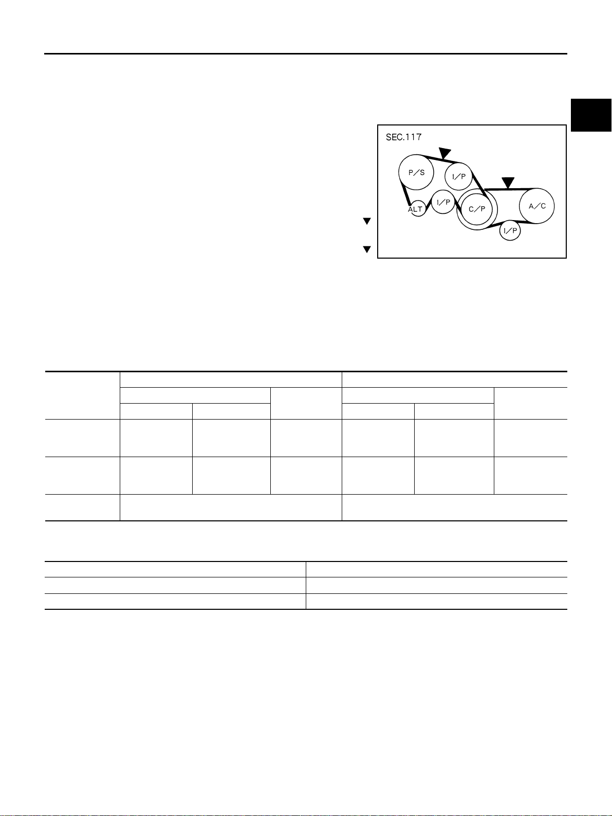
2. Inspect drive belt deflection or tension at a point on belt midway
between pulleys.
● Inspection should be done only when engine is cold, or over
30 minutes after engine is stopped.
● Measure belt tension with belt tension gauge (Commercial
Service Tool: BT3373-F or equivalent) at points marked
shown in the figure.
● When measuring deflection, apply 98 N (10 kg, 22 lb) at the
marked point.
● Adjust if belt deflection exceeds the limit or if belt tension is not within specifications.
CAUTION:
● When checking belt deflection or tension immediately after installation, first adjust it to the
specified value. Then, after turning crankshaft two turns or more, re-adjust to the specified
value to avoid variation in deflection between pulleys.
● Tighten idler pulley lock nut by hand and measure deflection or tension without looseness.
Belt Deflection and Tension
*: If belt tension gauge cannot be installed at check points shown, check drive belt tension at different location on belt.
Tension Adjustment ABS004TY
CAUTION:
● When belt is replaced with a new one, adjust it to value for “New belt” to accommodate for insuffi-
cient adaptability with pulley grooves.
● When deflection or tension of belt being used exceeds “Limit”, adjust it to value for “After adjust-
ment of used belt”.
● When checking belt deflection or tension immediately after installation, first adjust it to the speci-
fied value. Then, after turning crankshaft two turns or more, re-adjust to the specified value to
avoid variation in deflection between pulleys.
● When installing belt, make sure that it is correctly engaged with pulley grooves.
● Keep engine oil, working fluid and engine coolant away from belt and pulley grooves.
● Do not twist or bend belt excessively.
KBIA1731J
Items
Deflection adjustment Unit: mm (in) Tension adjustment* Unit: N (kg, lb)
Used belt
New belt
Used belt
New belt
Limit After adjustment Limit After adjustment
Alternator and
power steering
oil pump belt
7 (0.28)
4 - 5
(0.16 - 0.20)
3.5 - 4.5
(0.138 - 0.177)
294 (30, 66)
730 - 818
(74.5 - 83.5,
164 - 184)
838 - 926
(85.5 - 94.5,
188 - 208)
Air conditioner
compressor belt
12 (0.47)
9 - 10
(0.35 - 0.39)
8 - 9
(0.31 - 0.35)
196 (20, 44)
348 - 436
(35.5 - 44.5,
78 - 98)
470 - 559
(48 - 57,
106 - 126)
Applied pushing
force
98 N (10 kg, 22 lb) —
Portion Belt tightening method for adjustment
Alternator and power steering oil pump belt Adjusting bolt on idler pulley
Air conditioner compressor belt Adjusting bolt on idler pulley
EM-16
[VQ35DE]
DRIVE BELTS
Revision: 2004 November 2004 FX35/FX45
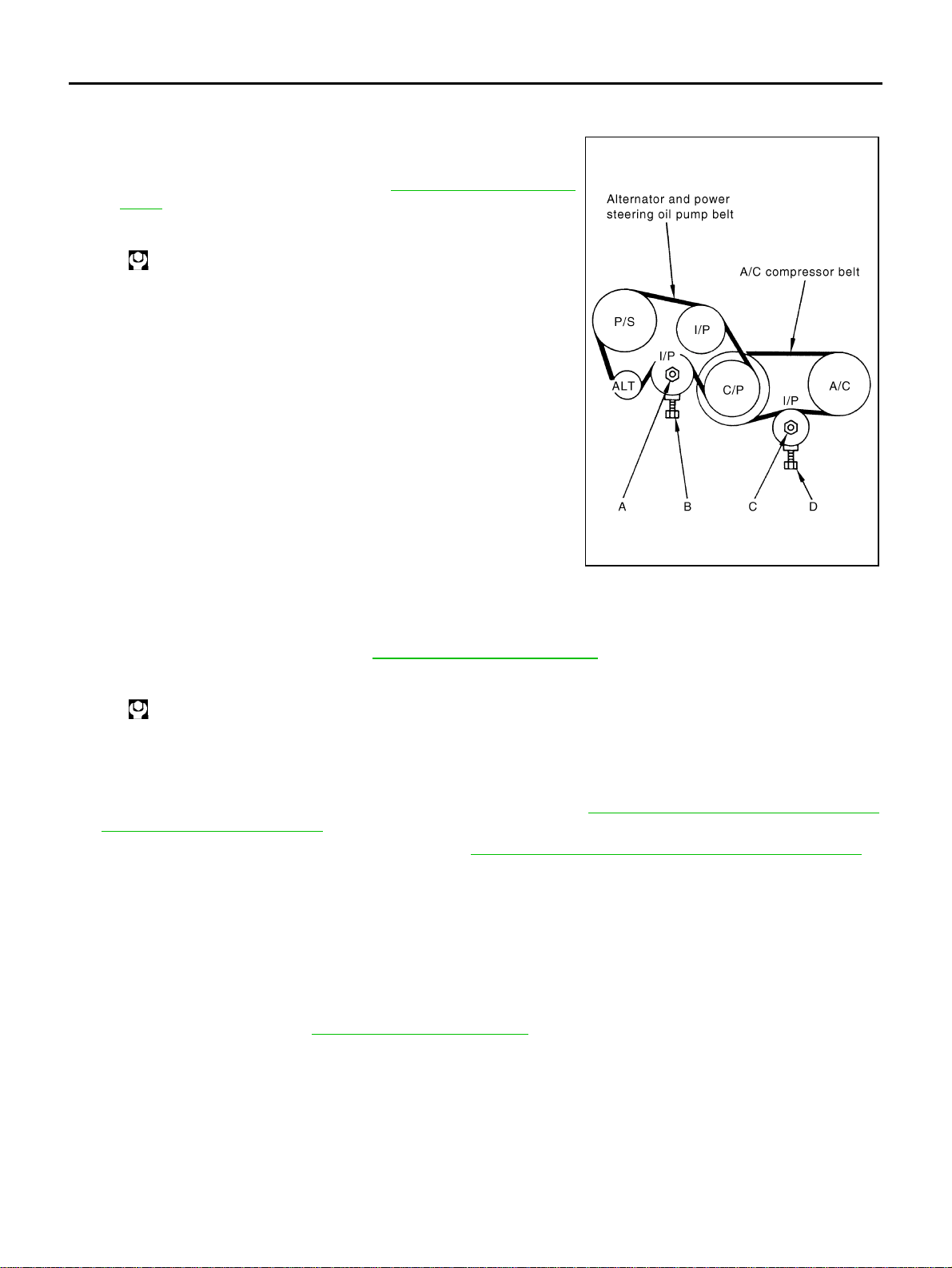
ALTERNATOR AND POWER STEERING OIL PUMP BELT
1. Remove front engine undercover with power tool.
2. Loosen idler pulley lock nut (A) and adjust tension by turning
adjusting bolt (B).
● For specified belt tension, refer to EM-15, "Checking Drive
Belts" .
3. Tighten nut (A).
AIR CONDITIONER COMPRESSOR BELT
1. Remove front engine undercover with power tool.
2. Loosen idler pulley lock nut (C) and adjust tension by turning adjusting bolt (D).
● For specified belt tension, refer to EM-15, "Checking Drive Belts" .
3. Tighten nut (C).
Removal and Installation ABS004TZ
REMOVAL
1. Remove front engine undercover with power tool.
2. Remove alternator and power steering oil pump belt. Refer to EM-16, "
ALTERNATOR AND POWER
STEERING OIL PUMP BELT" .
3. Remove air conditioner compressor belt. Refer to EM-16, "
AIR CONDITIONER COMPRESSOR BELT" .
CAUTION:
Grease is applied to idler pulley adjusting bolt. Be careful to keep grease away from belt.
INSTALLATION
1. Install belts to pulley in reverse order of removal.
CAUTION:
● Make sure belt is correctly engaged with pulley groove.
● Check for engine oil and engine coolant are not adhered to belt and each pulley grooves.
2. Adjust belt tension. Refer to EM-15, "
Tension Adjustment" .
3. Tighten each adjusting bolt and nut to the specified torque.
4. Make sure that tension of each belt is within the standard.
: 34.8 N·m (3.5 kg-m, 26 ft-lb)
SBIA0532E
: 34.8 N·m (3.5 kg-m, 26 ft-lb)
AIR CLEANER AND AIR DUCT
EM-17
[VQ35DE]
C
D
E
F
G
H
I
J
K
L
M
A
EM
Revision: 2004 November 2004 FX35/FX45
AIR CLEANER AND AIR DUCT PFP:16500
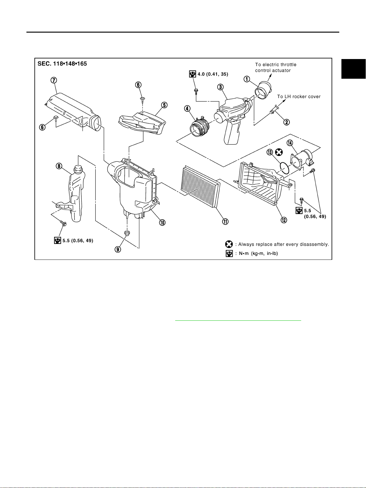
Removal and Installation ABS004U0
REMOVAL
1. Remove engine cover with power tool. Refer to EM-19, "INTAKE MANIFOLD COLLECTOR" .
● This work is unnecessary when parts located forward of mass air flow sensor are removed/installed.
2. Remove air duct (inlet).
3. Disconnect mass air flow sensor harness connector.
4. Disconnect PCV hose.
5. Remove air cleaner case/mass air flow sensor assembly and air duct/resonator assembly disconnecting
their joints.
● Add marks as necessary for easier installation.
6. Remove mass air flow sensor from air cleaner case.
CAUTION:
Handle mass air flow sensor with care.
● Do not shock it.
● Do not disassemble it.
● Do not touch its sensor.
7. Remove resonator in fender, lifting left fender protector.
INSTALLATION
Note to the following, and install in the reverse order of removal.
1. Air hose 2. PCV hose 3. Air duct
4. Air hose 5. Power duct 6. Clip
7. Air duct (inlet) 8. Resonator 9. Grommet
10. Air cleaner case 11. Air cleaner filter 12. Air cleaner case
13. O-ring 14. Mass air flow sensor
SBIA0462E
EM-18
[VQ35DE]
AIR CLEANER AND AIR DUCT
Revision: 2004 November 2004 FX35/FX45
● Align marks. Attach each joint. Screw clamps firmly.
● To position air cleaner case, refer to EM-18, "Changing Air Cleaner Filter" .
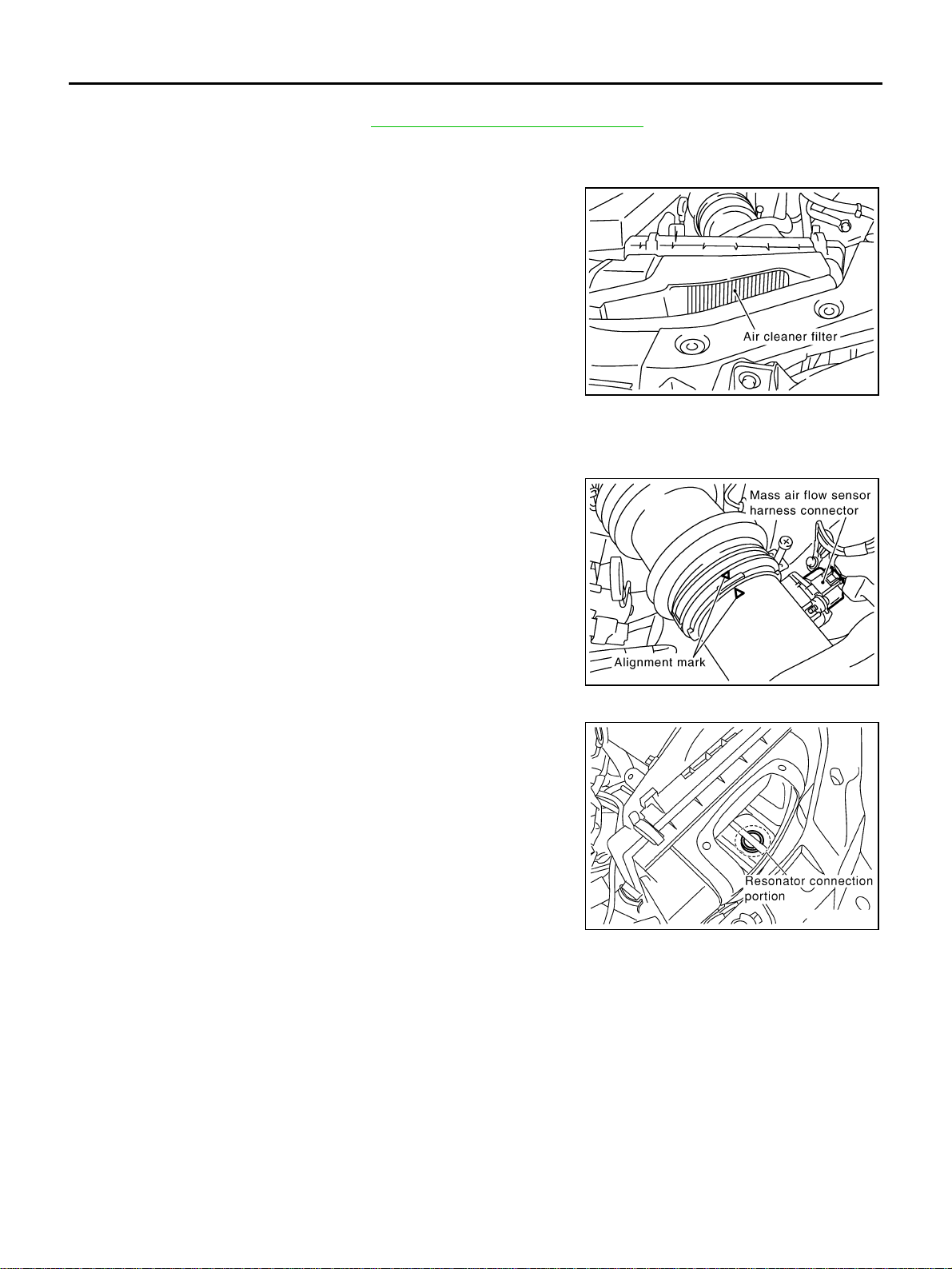
Changing Air Cleaner Filter ABS004U1
INSPECTION
Check status (fouling, damage, etc.) of air cleaner filter at power duct
hole.
REMOVAL
Removal in the order below.
1. Remove air duct (inlet) from air cleaner case.
2. Disconnect harness connector from mass air flow sensor.
3. Loosen clamp bolts of air hose.
4. Remove mounting bolts for air cleaner case. Remove air cleaner
case/mass air flow sensor/air hose assembly.
5. Unclip and open air cleaner case, and remove air cleaner filter.
INSTALLATION
Note to the following, and install in the reverse order of removal.
● If grommet at bottom of air cleaner case comes off together with
air cleaner case, fix it to vehicle before installation.
● Look at internal bottom face through power duct hole, and posi-
tion air cleaner case with resonator upper end circle and air
cleaner case round hole aligned. Then push air cleaner case
straight down.
● At this time, check by hand if protrusion at bottom of air cleaner
case has been inserted into grommet on vehicle side.
● Clip power duct with bulge on reverse side of lower end
engaged with air cleaner case.
SBIA0463E
SBIA0464E
KBIA0954E
INTAKE MANIFOLD COLLECTOR
EM-19
[VQ35DE]
C
D
E
F
G
H
I
J
K
L
M
A
EM
Revision: 2004 November 2004 FX35/FX45
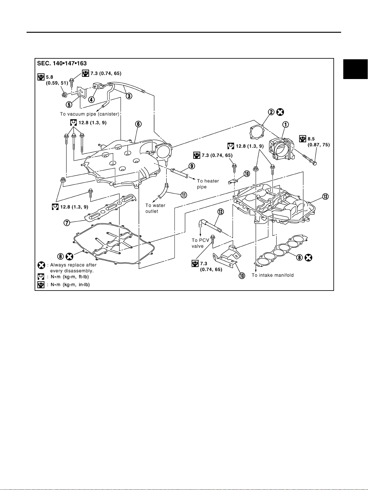
INTAKE MANIFOLD COLLECTOR PFP:14003
Removal and Installation ABS009RG
REMOVAL
WARNING:
● To avoid the danger of being scalded, never drain engine coolant when engine is hot.
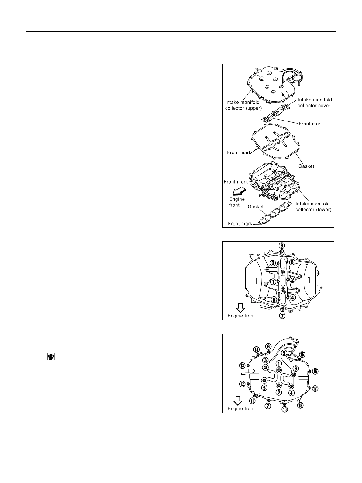
● Gasket for intake manifold collector (upper) is secured together with mounting bolt for intake man-
ifold collector (lower). Thus, even when only gasket for upper side is replaced, gasket for lower
side must be also replaced.
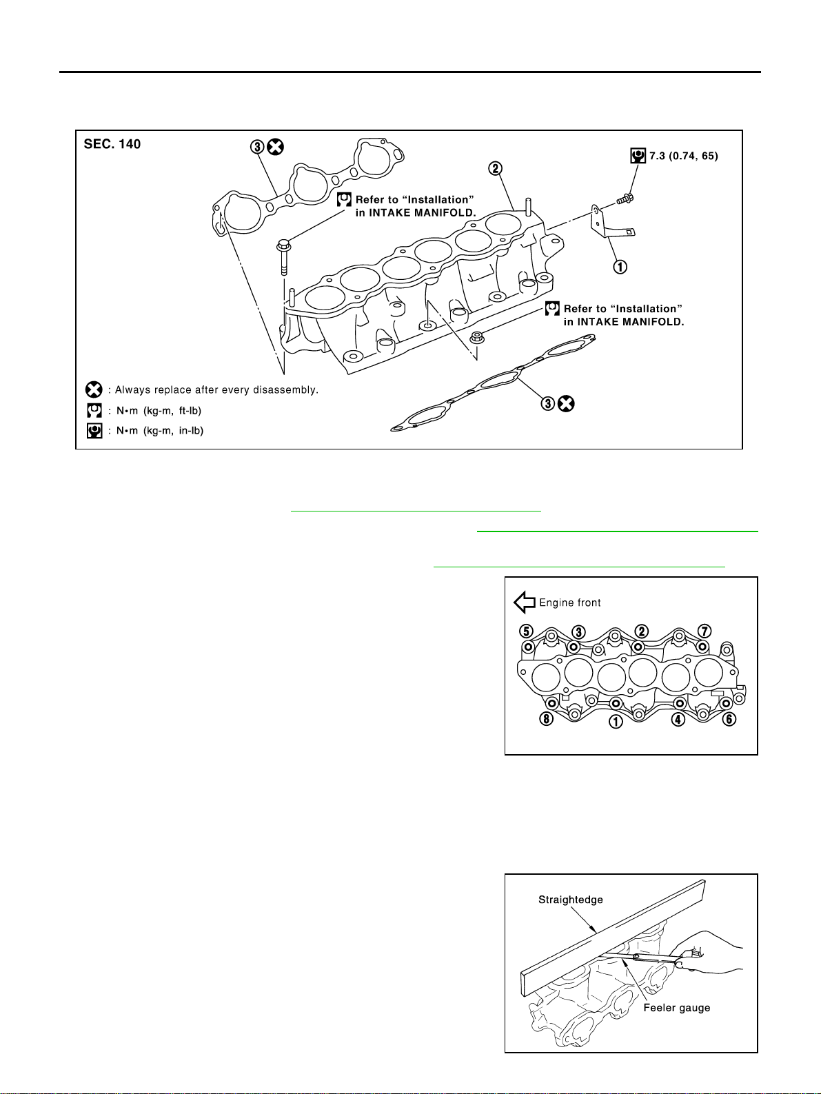
1. Electric throttle control actuator 2. Gasket 3. Vacuum hose
4.
EVAP canister purge volume control
solenoid valve
5. Bracket 6. Intake manifold collector (upper)
7. Intake manifold collector cover 8. Gasket 9. Water hose
10. Bracket 11. Water hose 12. PCV hose
13. Intake manifold collector (lower)
SBIA0585E
EM-20
[VQ35DE]
INTAKE MANIFOLD COLLECTOR
Revision: 2004 November 2004 FX35/FX45
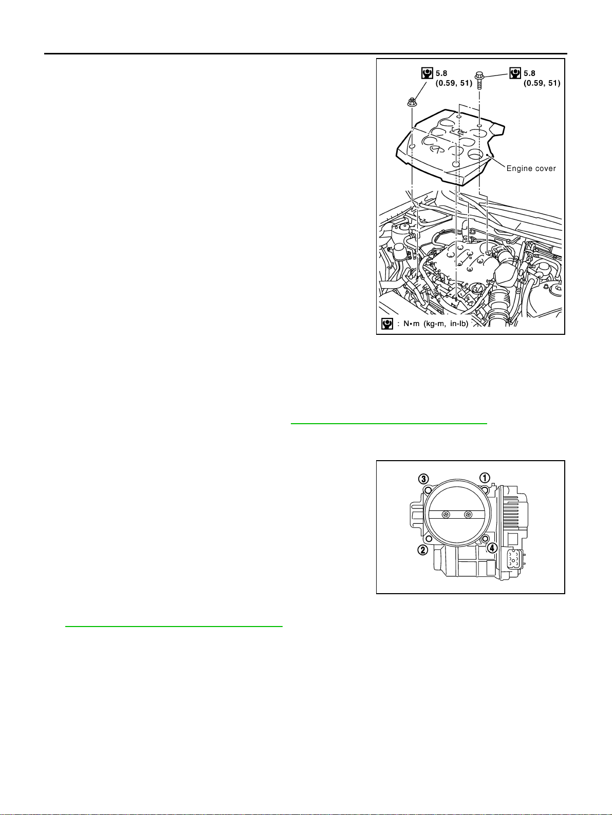
1. Remove engine cover with power tool.
2. Disconnect water hoses from intake manifold collector (upper), attach blind plug to prevent engine coolant
leakage.
CAUTION:
● Perform this step when engine is cold.
● Do not spill engine coolant on drive belts.
3. Remove air cleaner case and air duct. Refer to EM-17, "
AIR CLEANER AND AIR DUCT" .
4. Remove electric throttle control actuator as the following:
a. Disconnect harness connector.
b. Loosen bolts in reverse order as shown in the figure.
CAUTION:
● Handle carefully to avoid any shock to electric throttle
control actuator.
● Do not disassemble.
5. Remove fuel sub-tube mounting bolt to disconnect from rear of intake manifold collector (lower). Refer to
EM-45, "
FUEL INJECTOR AND FUEL TUBE" .
6. Disconnect vacuum hose and water hose from intake manifold collector (upper).
7. Remove EVAP canister purge volume control solenoid valve bracket mounting bolt from intake manifold
collector (upper).
SBIA0486E
KBIA0957E
INTAKE MANIFOLD COLLECTOR
EM-21
[VQ35DE]
C
D
E
F
G
H
I
J
K
L
M
A
EM
Revision: 2004 November 2004 FX35/FX45
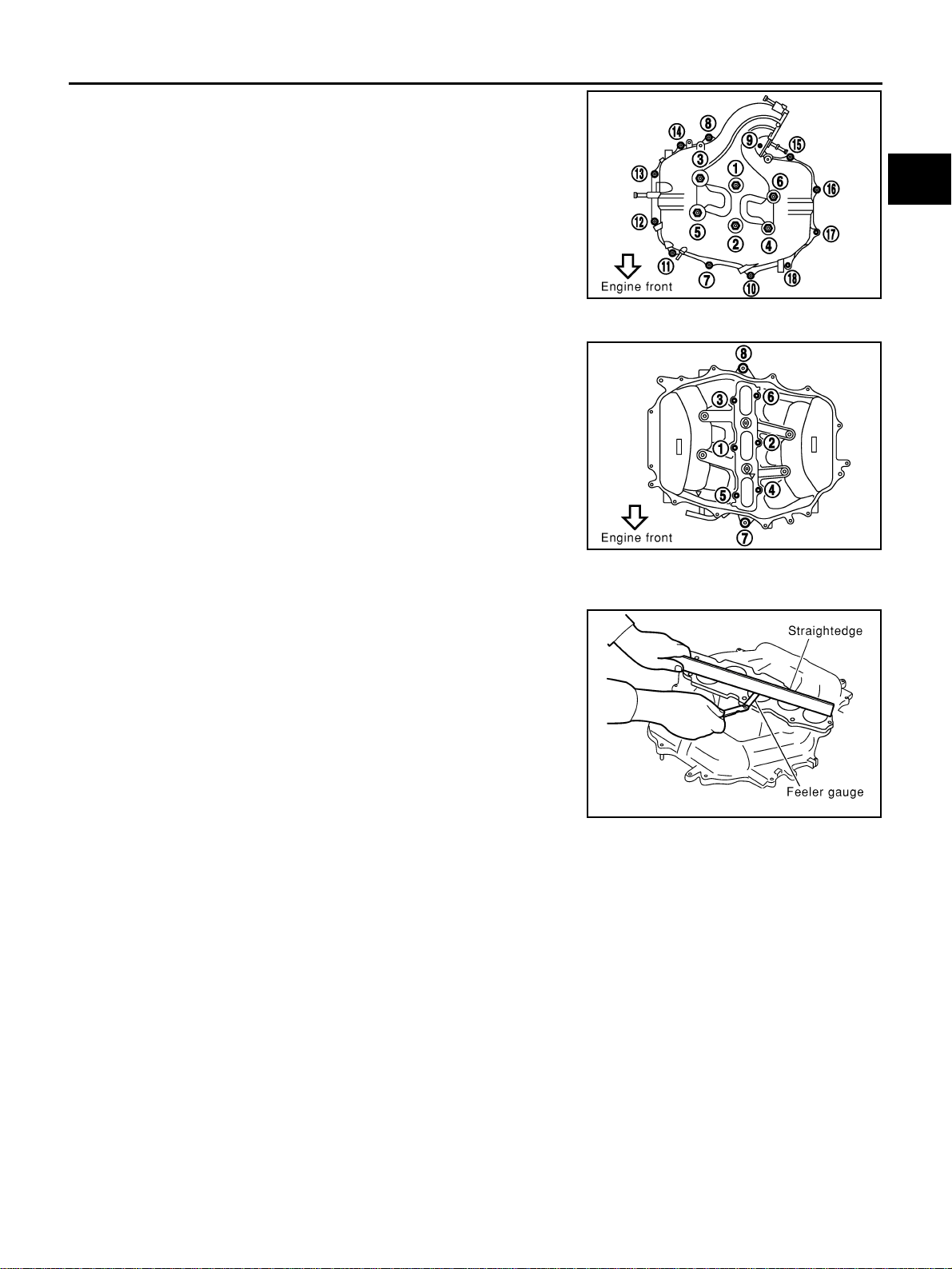
8. Loosen bolts in reverse order as shown in the figure to remove
intake manifold collector (upper) with power tool.
9. Remove PCV hose [between intake manifold collector and rocker cover (right bank)].
10. Loosen bolts in reverse order as shown in the figure, and
remove intake manifold collector cover, gasket, intake manifold
collector (lower) and gasket with power tool.
CAUTION:
Cover engine openings to avoid entry of foreign materials.
INSPECTION AFTER REMOVAL
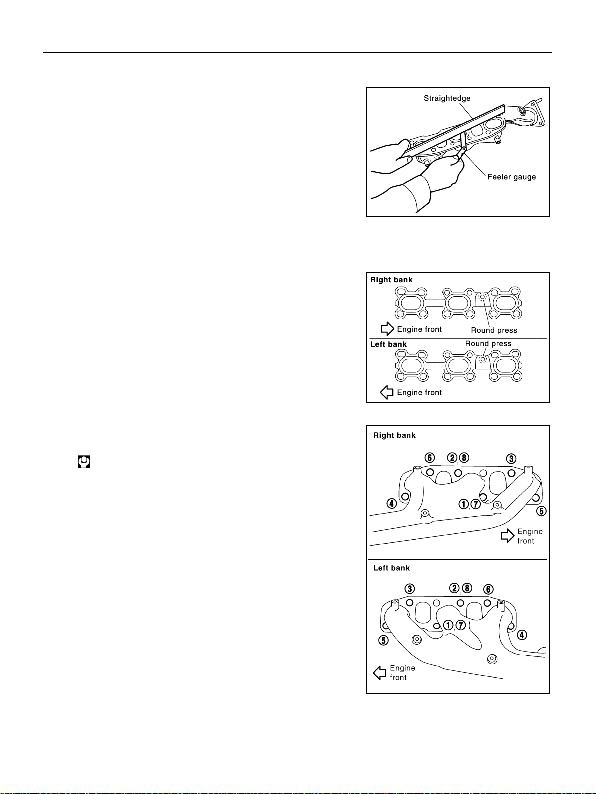
Surface Distortion
● Check the surface distortion of both the intake manifold collector
(upper and lower) mating surfaces with straightedge and feeler
gauge.
● If it exceeds the limit, replace intake manifold collector (upper
and/or lower).
PBIC0773E
PBIC0774E
Limit : 0.1 mm (0.004 in)
PBIC0775E
EM-22
[VQ35DE]
INTAKE MANIFOLD COLLECTOR
Revision: 2004 November 2004 FX35/FX45
INSTALLATION
Note to the following, and install in the reverse order of removal.
Part Installation Direction
Referring to front marks, install parts shown in figure.
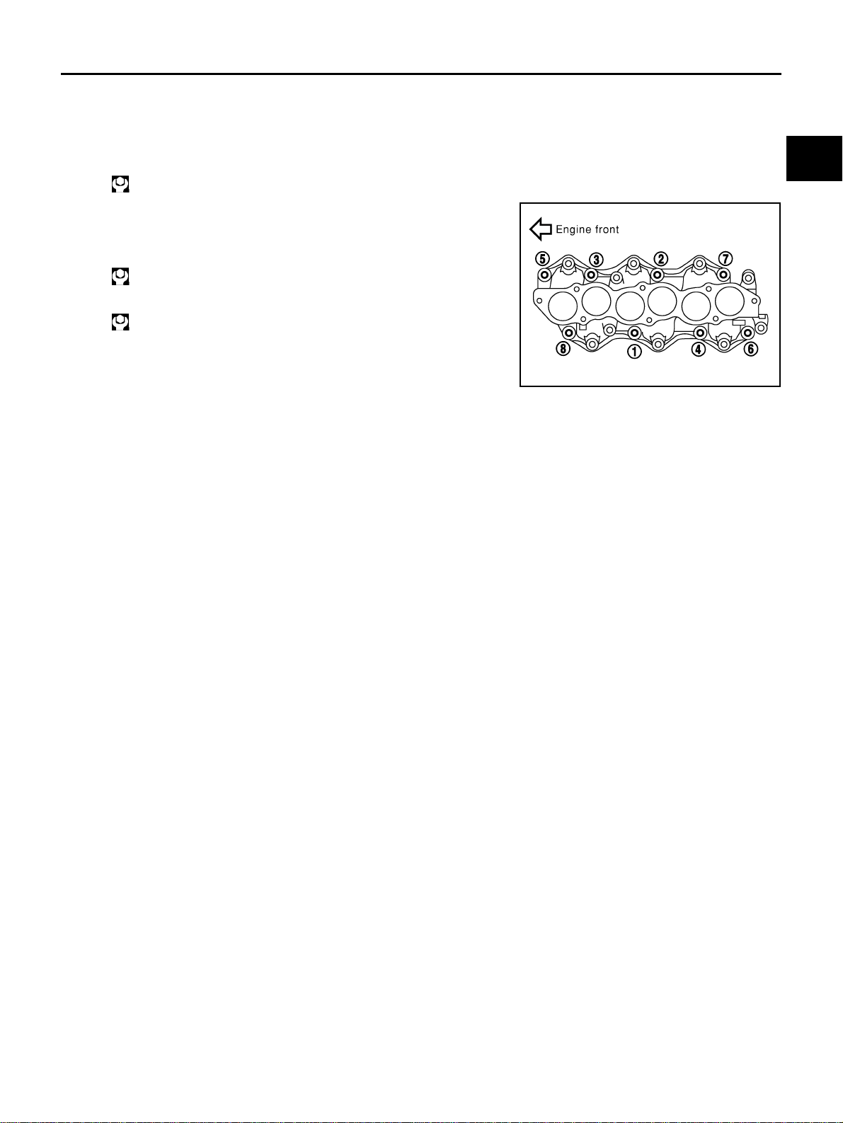
Intake Manifold Collector (Lower)
Tighten in numerical order as shown in the figure.
NOTE:
Tighten mounting bolts to secure gasket (lower), intake manifold col-
lector (lower), gasket (upper), and intake manifold collector cover.
Intake Manifold Collector (Upper)
● If stud bolts were removed, install them and tighten to the speci-
fied torque below.
● Shank length under bolt head varies with bolt location. Install
bolts while referring to numbers shown below and in figure. (Bolt
length does not include pilot portion.)
● Tighten in numerical order as shown in the figure.
Water Hose
● Insert hose by 27 to 32 mm (1.06 to 1.26 in) from connector end.
PBIC0776E
PBIC0774E
: 5.9 N·m (0.6 kg-m, 52 in-lb)
Bolt
M6 × 25 mm (0.98 in) : 7, 8, 10, 11, 13, 14, 15, 16, 18
M6 × 45 mm (1.77 in) : 2, 4, 5
M6 × 60 mm (2.36 in) : 1, 3, 6, 9
M6 Nut : 12, 17
PBIC0773E
INTAKE MANIFOLD COLLECTOR
EM-23
[VQ35DE]
C
D
E
F
G
H
I
J
K
L
M
A
EM
Revision: 2004 November 2004 FX35/FX45
● Clamp hose at location of 3 to 7 mm (0.12 to 0.28 in) from hose end.
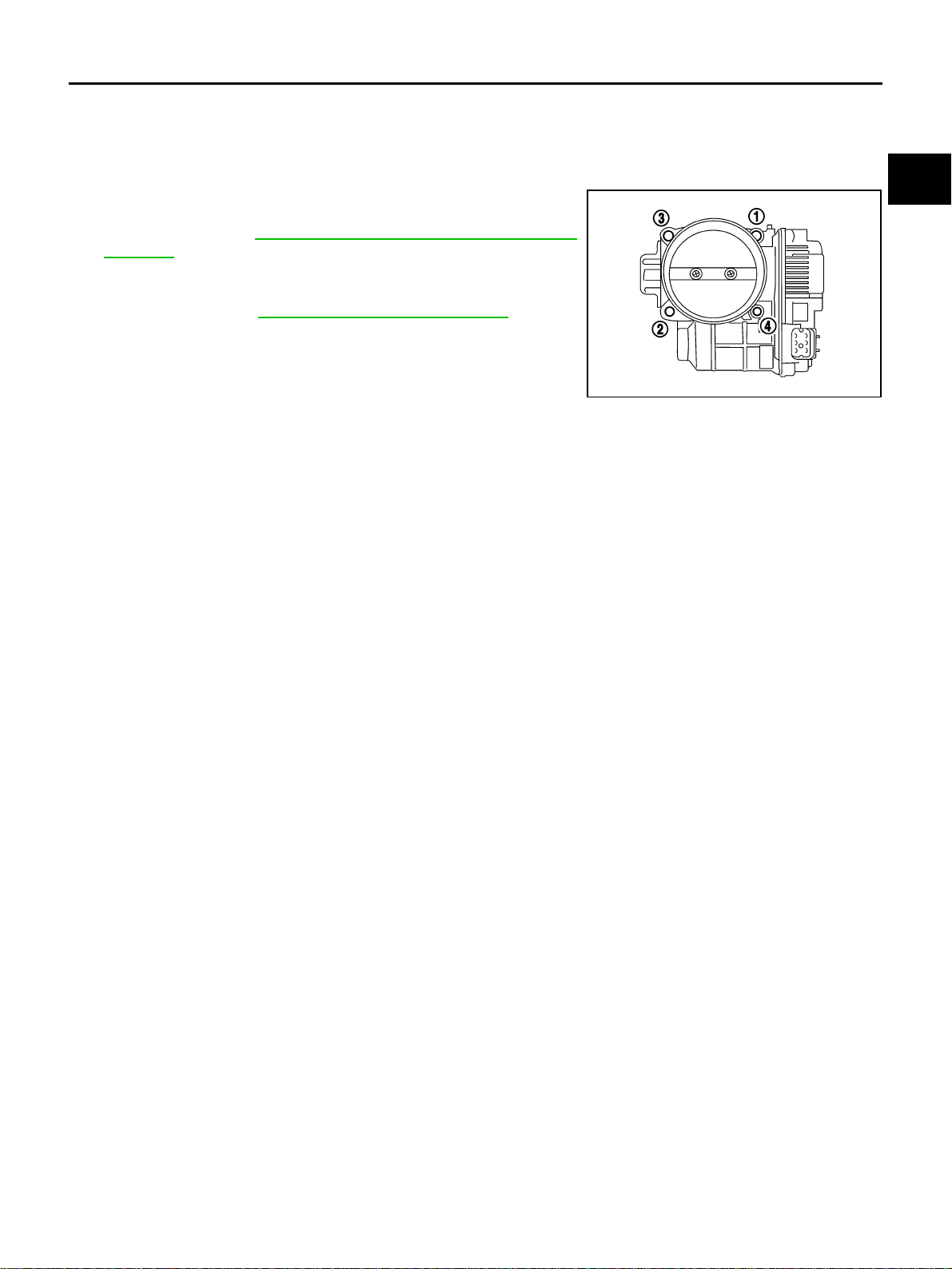
Electric Throttle Control Actuator
● Install gasket with three protrusions for installation check facing any direction other than upward.
● Tighten in numerical order as shown in the figure.
● Perform the “Throttle Valve Closed Position Learning” when har-
ness connector of electric throttle control actuator is discon-
nected. Refer to EC-49, "
Throttle Valve Closed Position
Learning" .
● Perform the “Idle Air Volume Learning” and “Throttle Valve
Closed Position Learning” when electric throttle control actuator
is replaced. Refer to EC-49, "
Idle Air Volume Learning" .
KBIA0957E
EM-24
[VQ35DE]
INTAKE MANIFOLD
Revision: 2004 November 2004 FX35/FX45
INTAKE MANIFOLD PFP:14003
Removal and Installation ABS004U3
REMOVAL
1. Release fuel pressure. Refer to EC-51, "FUEL PRESSURE RELEASE" .
2. Remove intake manifold collector (upper and lower). Refer to EM-19, "
INTAKE MANIFOLD COLLECTOR"
.
3. Remove fuel tube and fuel injector assembly. Refer to EM-45, "
FUEL INJECTOR AND FUEL TUBE" .
4. Loosen bolts and nuts in reverse order of illustration to remove
intake manifold with power tool.
5. Remove intake manifold gaskets.
CAUTION:
Cover engine openings to avoid entry of foreign materials.
INSPECTION AFTER REMOVAL
Surface Distortion
● Check the surface distortion of the intake manifold mating sur-
face with straightedge and feeler gauge.
● If it exceeds the limit, replace intake manifold.
1. Harness bracket 2. Intake manifold 3. Gasket
SBIA0487E
PBIC0778E
Limit : 0.1 mm (0.04 in)
PBIC0870E
INTAKE MANIFOLD
EM-25
[VQ35DE]
C
D
E
F
G
H
I
J
K
L
M
A
EM
Revision: 2004 November 2004 FX35/FX45
INSTALLATION
Note to the following, and install in the reverse order of removal.
Intake Manifold
● If stud bolts were removed, install them and tighten to the specified torque below.
● Tighten all mounting bolts and nuts to the specified torque in two
or more steps in numerical order shown in the figure.
: 10.8 N·m (1.1 kg-m, 8 ft-lb)
1st step:
: 7.4 N·m (0.75 kg-m, 5 ft-lb)
2nd step and after:
: 29.0 N·m (3.0 kg-m, 21 ft-lb)
PBIC0778E
EM-26
[VQ35DE]
EXHAUST MANIFOLD AND THREE WAY CATALYST
Revision: 2004 November 2004 FX35/FX45
EXHAUST MANIFOLD AND THREE WAY CATALYST PFP:14004
Removal and Installation ABS004U4
REMOVAL
WARNING:
Perform the work when the exhaust and cooling system have completely cooled down.
1. Remove engine cover with power tool. Refer to EM-19, "
INTAKE MANIFOLD COLLECTOR" .
2. Remove air cleaner case and air duct. Refer to EM-17, "
AIR CLEANER AND AIR DUCT" .
3. Remove front and rear engine undercover and front cross bar with power tool.
4. Disconnect heated oxygen sensors 2 (bank 1 and bank 2) harness connectors.
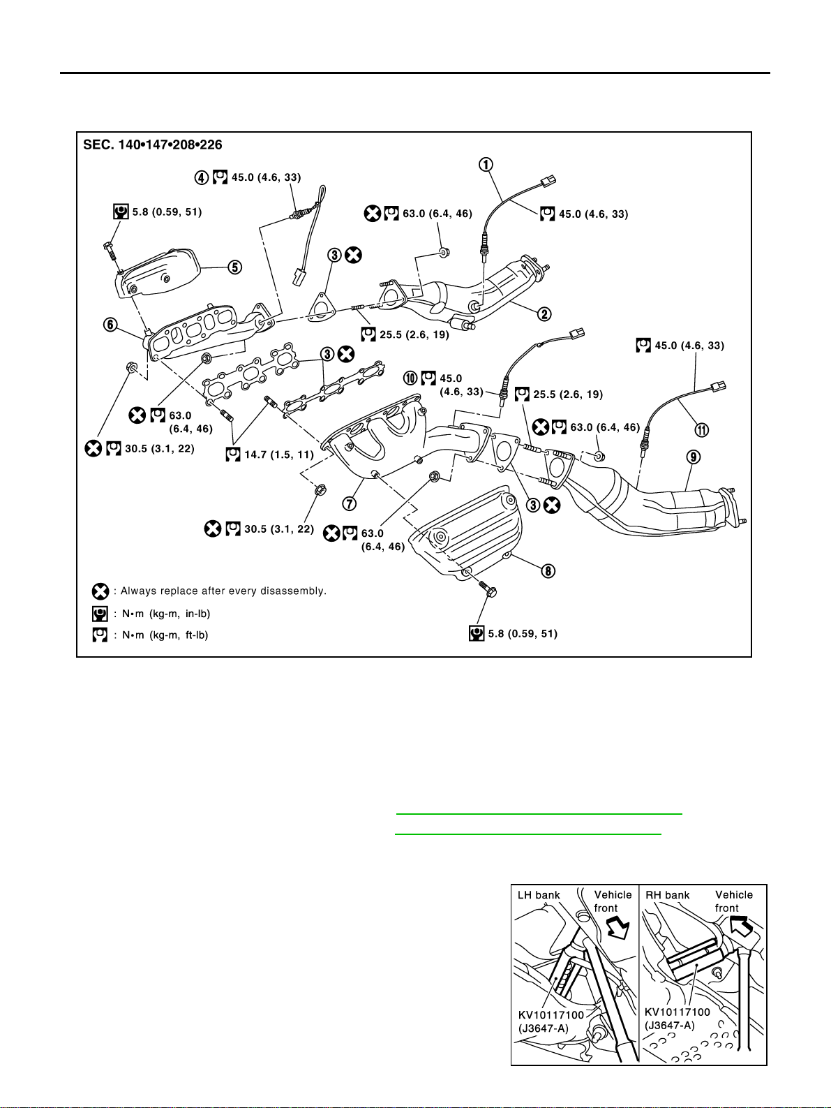
5. Using heated oxygen sensor wrench (SST), remove heated oxy-
gen sensors 2 (bank 1 and bank 2).
CAUTION:
● Be careful not to damage heated oxygen sensor.
● Discard any heated oxygen sensor which has been
dropped from a height of more than 0.5 m (19.7 in) onto a
hard surface such as a concrete floor; replace with a new
sensor.
1. Heated oxygen sensor 2 (bank 1) 2. Three way catalyst (right bank) 3. Gasket
4. heated oxygen sensor 1 (bank 1) 5. Exhaust manifold cover (right bank) 6. Exhaust manifold (right bank)
7. Exhaust manifold (left bank) 8. Exhaust manifold cover (left bank) 9. Three way catalyst (left bank)
10. heated oxygen sensor 1 (bank 2) 11. Heated oxygen sensor 2 (bank 2)
SBIA0583E
KBIA1740E
EXHAUST MANIFOLD AND THREE WAY CATALYST
EM-27
[VQ35DE]
C
D
E
F
G
H
I
J
K
L
M
A
EM
Revision: 2004 November 2004 FX35/FX45
6. Remove exhaust mounting bracket between right/left catalytic converter and transmission. Refer to EX-3,
"EXHAUST SYSTEM" .
7. Remove three way catalyst (right and left bank).
8. Disconnect heated oxygen sensor 1 (bank 1 and bank 2) harness connectors and remove harness clip.
9. Using heated oxygen sensor wrench (SST), remove heated oxy-
gen sensor 1 (bank 1 and bank 2).
CAUTION:
● Be careful not to damage heated oxygen sensor.
● Discard any heated oxygen sensor which has been
dropped from a height of more than 0.5 m (19.7 in) onto a
hard surface such as a concrete floor; replace with a new
sensor.
10. Remove water pipes on both right and left side. Refer to CO-28, "
WATER OUTLET AND WATER PIPING"
.
11. Remove exhaust manifold cover (right and left bank).
12. Loosen nuts in the reverse order as shown in the figure to
remove exhaust manifold with power tool.
NOTE:
Disregard the numerical order No. 7 and No. 8 in removal.
13. Remove exhaust manifold gaskets.
CAUTION:
Cover engine openings to avoid entry of foreign materials.
SBIA0575E
PBIC2042E
EM-28
[VQ35DE]
EXHAUST MANIFOLD AND THREE WAY CATALYST
Revision: 2004 November 2004 FX35/FX45
INSPECTION AFTER REMOVAL
Surface Distortion
● Check the surface distortion of the exhaust manifold mating sur-
face with straightedge and feeler gauge.
● If it exceeds the limit, replace exhaust manifold.
INSTALLATION
Note to the following, and install in the reverse order of removal.
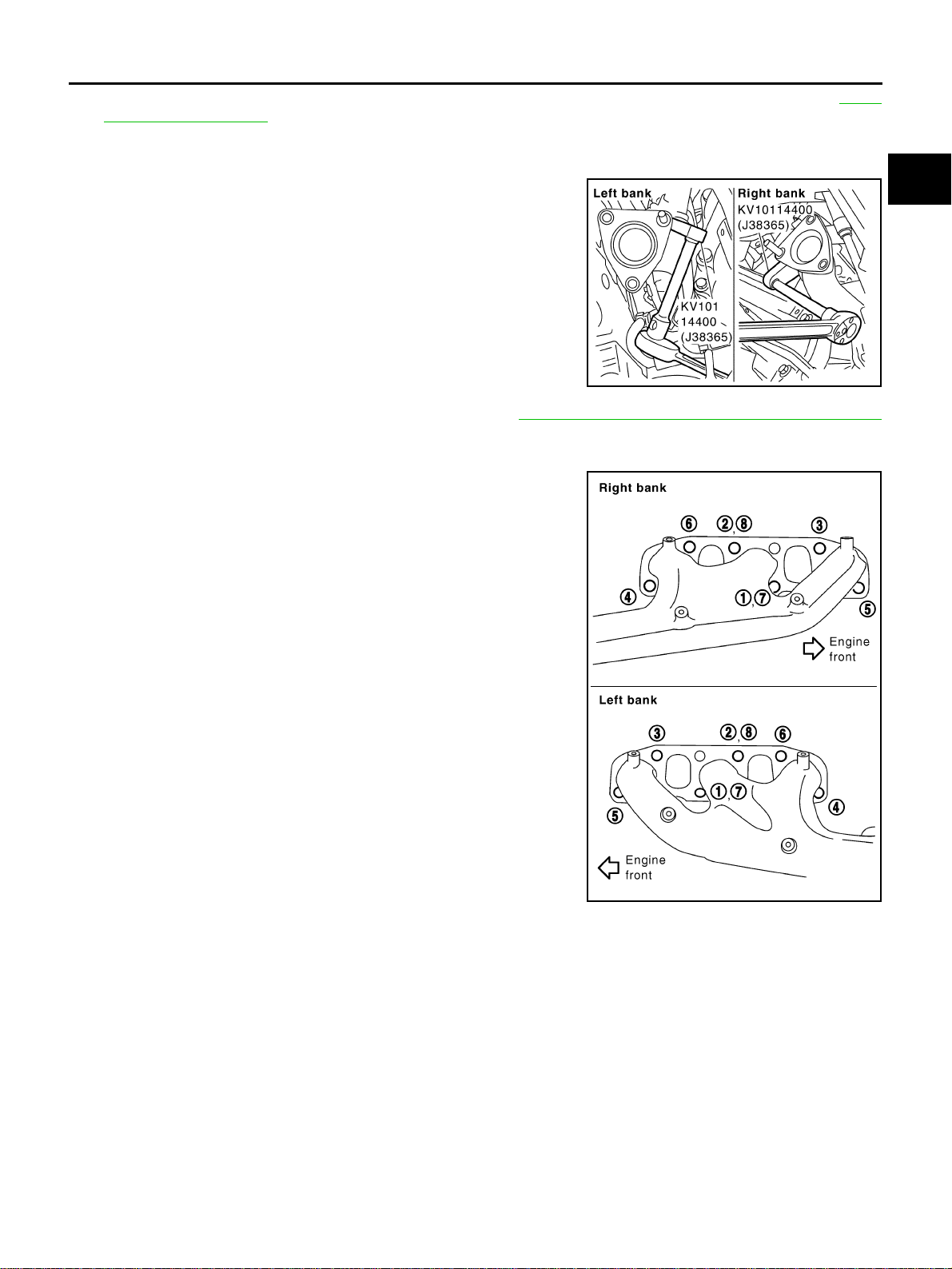
Exhaust Manifold Gasket
● Install in direction shown below. (Follow same procedure for
both banks.)
● Locate thick side of port connecting part on right side from tech-
nician’s view.
● Locate round press in thick side of port connecting part above
center level line of port.
Exhaust Manifold
● If stud bolts were removed, install them and tighten to the speci-
fied torque below.
● Install exhaust manifold in the numerical order as shown in the
figure.
NOTE:
Tighten nuts No. 1 and No. 2 in two steps. The numerical order
No. 7 and No. 8 shows second step.
Heated Oxygen Sensor
CAUTION:
● Before installing a new heated oxygen sensor, clean exhaust system threads using heated oxygen
sensor thread cleaner tool (Commercial Service Tool: J-43897-18 or J-43897-12) and apply anti-
seize lubricant.
Limit : 0.3 mm (0.012 in)
PBIC1096E
KBIA1051E
: 14.7 N·m (1.5 kg-m, 11 ft-lb)
PBIC2042E

EXHAUST MANIFOLD AND THREE WAY CATALYST
EM-29
[VQ35DE]
C
D
E
F
G
H
I
J
K
L
M
A
EM
Revision: 2004 November 2004 FX35/FX45
● Do not over torque heated oxygen sensor. Doing so may cause damage to heated oxygen sensor,
resulting in the “MIL” coming on.
EM-30
[VQ35DE]
OIL PAN AND OIL STRAINER
Revision: 2004 November 2004 FX35/FX45
OIL PAN AND OIL STRAINER PFP:11110
Removal and Installation ABS004U5
2WD MODEL
REMOVAL
CAUTION:
To avoid the danger of being scalded, never drain engine oil when engine is hot.
NOTE:
To remove oil pan (lower) only, take step 5, then step 20. Removal of step 1, hood assembly (step 2) and step
4 are unnecessary.
1. Remove front tire.
2. Remove hood assembly. Refer to BL-14, "
HOOD" .
3. Remove front and rear engine undercover with power tool.
4. Remove front cross bar with power tool. FSU-6, "FRONT SUSPENSION ASSEMBLY" .
5. Drain engine oil. Refer to LU-9, "
Changing Engine Oil" .
6. Drain engine coolant. Refer to CO-11, "
Changing Engine Coolant" .
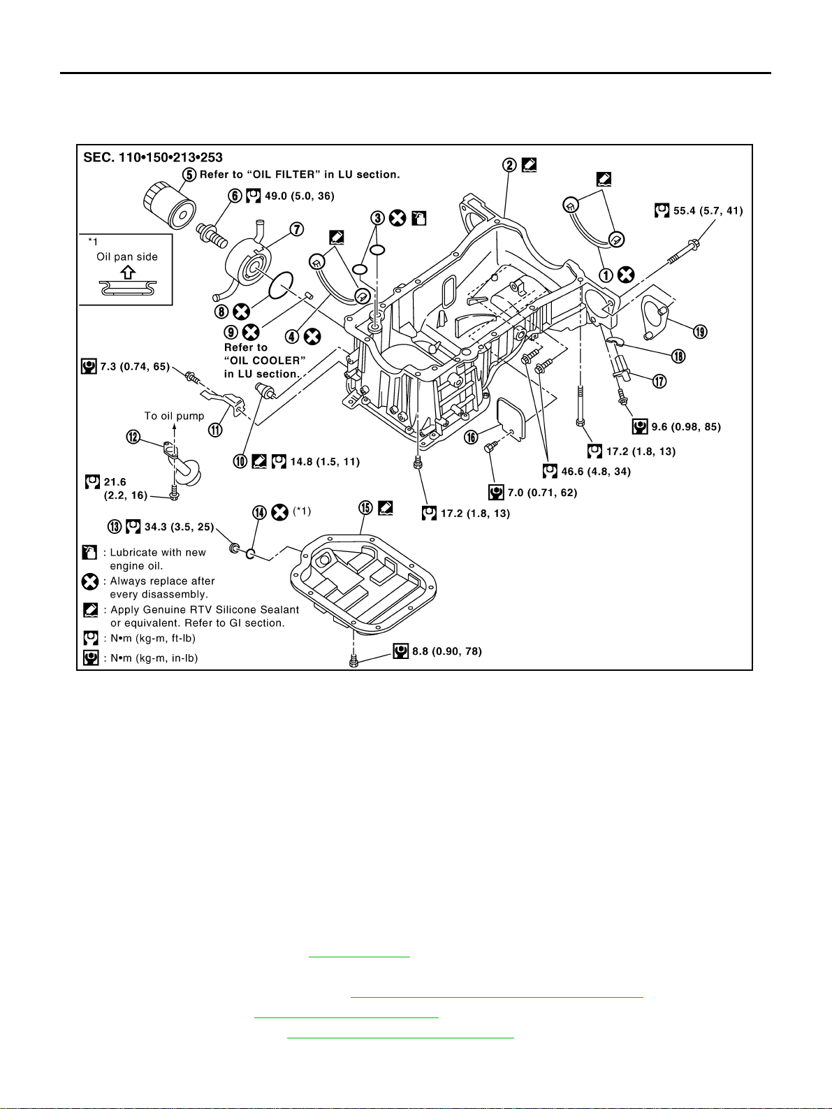
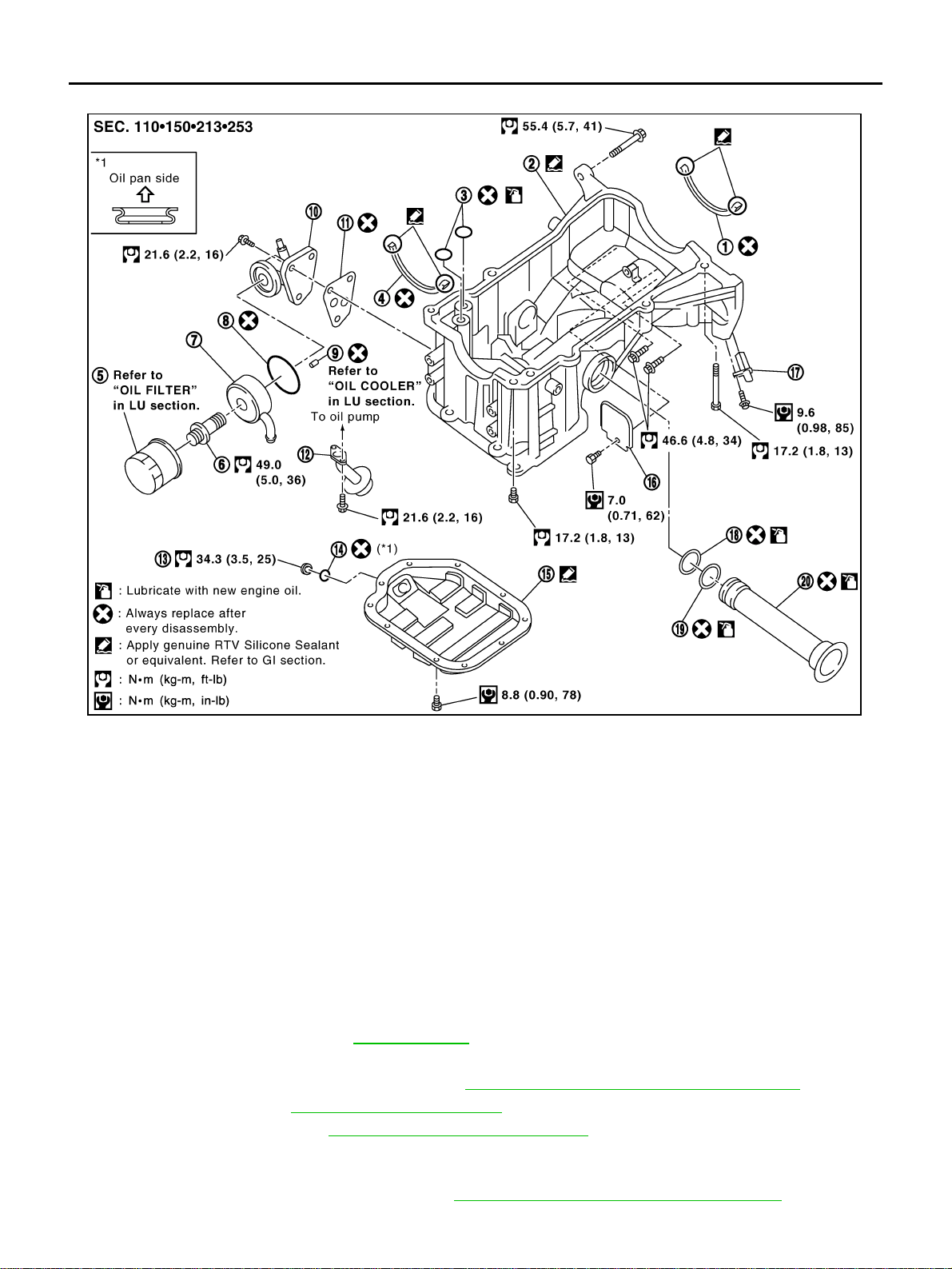
1. Oil pan gasket (rear) 2. Oil pan (upper) 3. O-ring
4. Oil pan gasket (front) 5. Oil filter 6. Connector bolt
7. Oil cooler 8. O-ring 9. Relief valve
10. Oil pressure switch 11. Bracket 12. Oil strainer
13. Drain plug 14. Drain plug washer 15. Oil pan (lower)
16. Rear plate 17. Crankshaft position sensor (POS) 18. Seal rubber
19. Rear cover plate
SBIA0587E
OIL PAN AND OIL STRAINER
EM-31
[VQ35DE]
C
D
E
F
G
H
I
J
K
L
M
A
EM
Revision: 2004 November 2004 FX35/FX45
CAUTION:
Perform when engine is cold.
7. Remove engine cover with power tool. Refer to EM-19, "
INTAKE MANIFOLD COLLECTOR" .
8. Remove air hose from air duct to mass air flow sensor side and electric throttle control actuator side.
Refer to EM-17, "
AIR CLEANER AND AIR DUCT" .
9. Removal engine rear lower slinger, and install engine rear slinger to sling engine assembly for positioning.
Refer to EM-8, "
Special Service Tools" .
10. Remove front suspension member. Refer to FSU-17, "
FRONT SUSPENSION MEMBER" .
11. Remove drive belt for alternator and power steering pump and A/C compressor. Refer to EM-15, "
DRIVE
BELTS" .
12. Remove alternator stay. Refer to SC-23, "
CHARGING SYSTEM" .
13. Remove starter motor. Refer to SC-10, "
STARTING SYSTEM" .
14. Remove alternator and power steering pump and A/C compressor idler pulley and bracket assembly.
Refer to EM-15, "
DRIVE BELTS" .
15. Disconnect A/T fluid cooler hoses, and remove oil cooler water pipe mounting bolt. Refer to LU-14, "
OIL
COOLER" .
16. Disconnect A/T fluid cooler tube.
17. Remove crankshaft position sensor (POS).
CAUTION:
● Handle carefully to avoid dropping and shocks.
● Do not disassemble.
● Do not allow metal powder to adhere to magnetic part at sensor tip.
● Do not place sensors in a location where they are exposed to magnetism.
18. Remove oil filter, as necessary. Refer to LU-10, "
OIL FILTER" .
19. Remove oil cooler, as necessary. Refer to LU-14, "
OIL COOLER" .
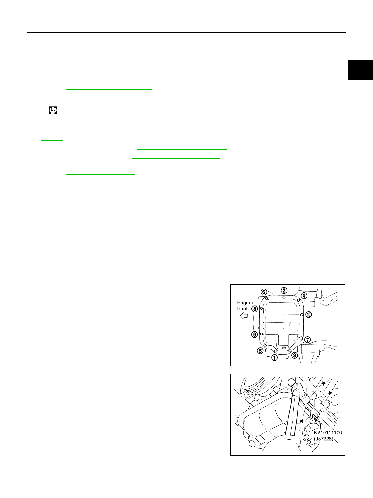
20. Remove oil pan (lower) as the following:
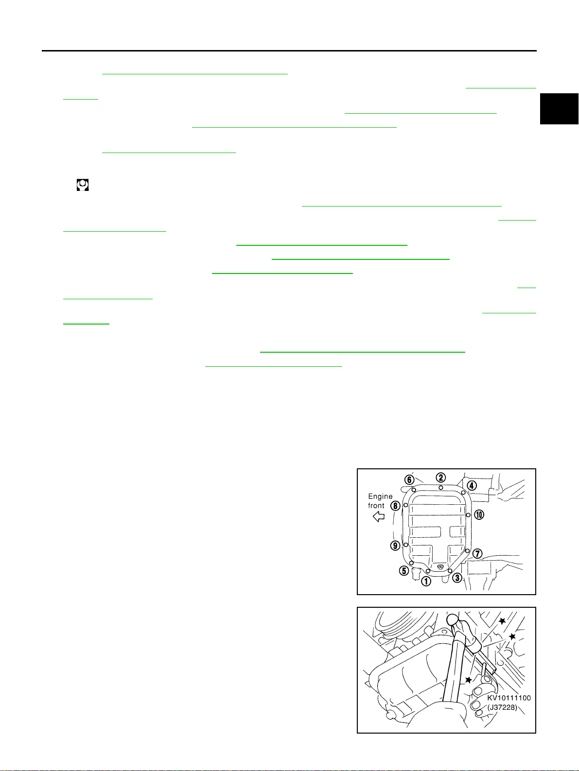
a. Loosen bolts in reverse order as shown in the figure to remove.
b. Insert seal cutter (SST) between oil pan (upper) and oil pan
(lower).
c. Slide seal cutter by tapping on the side of tool with hammer.
Remove oil pan (lower).
CAUTION:
● Be careful not to damage the mating surface.
● Do not insert flat-bladed screwdriver, this will damage the
mating surface.
21. Remove oil strainer.
Slinger bolts:
: 28.0 N·m (2.9 kg-m, 21 ft-lb)
PBIC0782E
SEM960F
EM-32
[VQ35DE]
OIL PAN AND OIL STRAINER
Revision: 2004 November 2004 FX35/FX45
22. Remove transmission joint bolts which pierce oil pan (upper). Refer to AT-266, "TRANSMISSION ASSEM-
BLY" .
23. Remove rear cover plate.
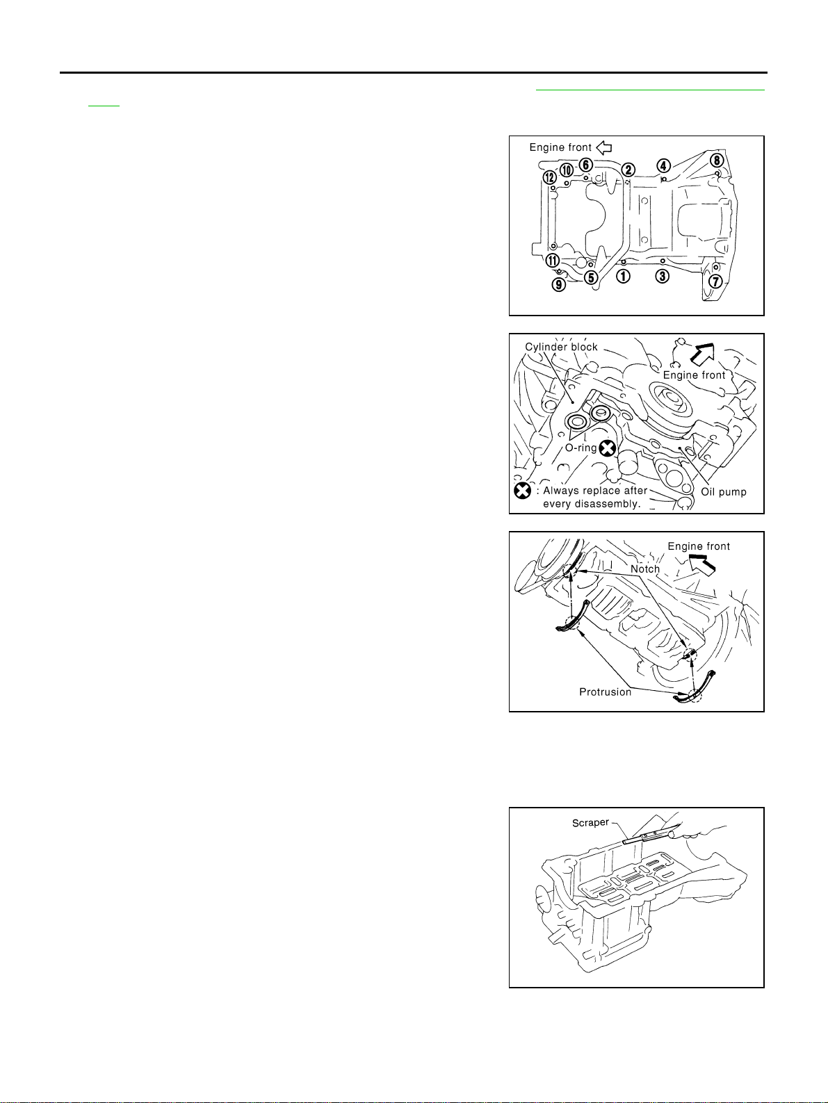
24. Loosen oil pan (upper) bolts with power tool in the reverse order
as shown in the figure to remove.
● Insert seal cutter [SST: KV10111100 (J-37228)] between oil
pan (upper) and cylinder block. Slide seal cutter by tapping on
the side of tool with a hammer. Remove oil pan (upper).
CAUTION:
● Be careful not to damage the mating surface.
● Do not insert a screwdriver, this will damage the mat-
ing surfaces.
25. Remove O-rings from bottom of cylinder block and oil pump.
26. Remove oil pan gaskets.
INSPECTION AFTER REMOVAL
Clean oil strainer if any object attached.
INSTALLATION
1. Install oil pan (upper) as the following:
a. Use scraper to remove old liquid gasket from mating surfaces.
CAUTION:
Do not scratch or damage the mating surfaces when clean-
ing off old liquid gasket.
● Also remove old liquid gasket from mating surface of cylinder
block.
● Remove old liquid gasket from the bolt holes and threads.
PBIC0783E
PBIC1144E
PBIC1145E
MEM108A
OIL PAN AND OIL STRAINER
EM-33
[VQ35DE]
C
D
E
F
G
H
I
J
K
L
M
A
EM
Revision: 2004 November 2004 FX35/FX45
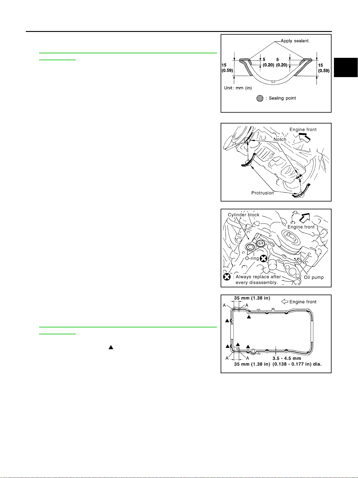
b. Apply liquid gasket to oil pan gaskets as shown in the figure.
Use Genuine RTV Silicone Sealant or equivalent. Refer to
GI-48, "
RECOMMENDED CHEMICAL PRODUCTS AND
SEALANTS" .
● To install, align protrusion of oil pan gasket with notches of
front timing chain case and rear oil seal retainer.
● Install oil pan gasket with smaller arc to front timing chain
case side.
c. Install new O-rings on cylinder block and oil pump side.
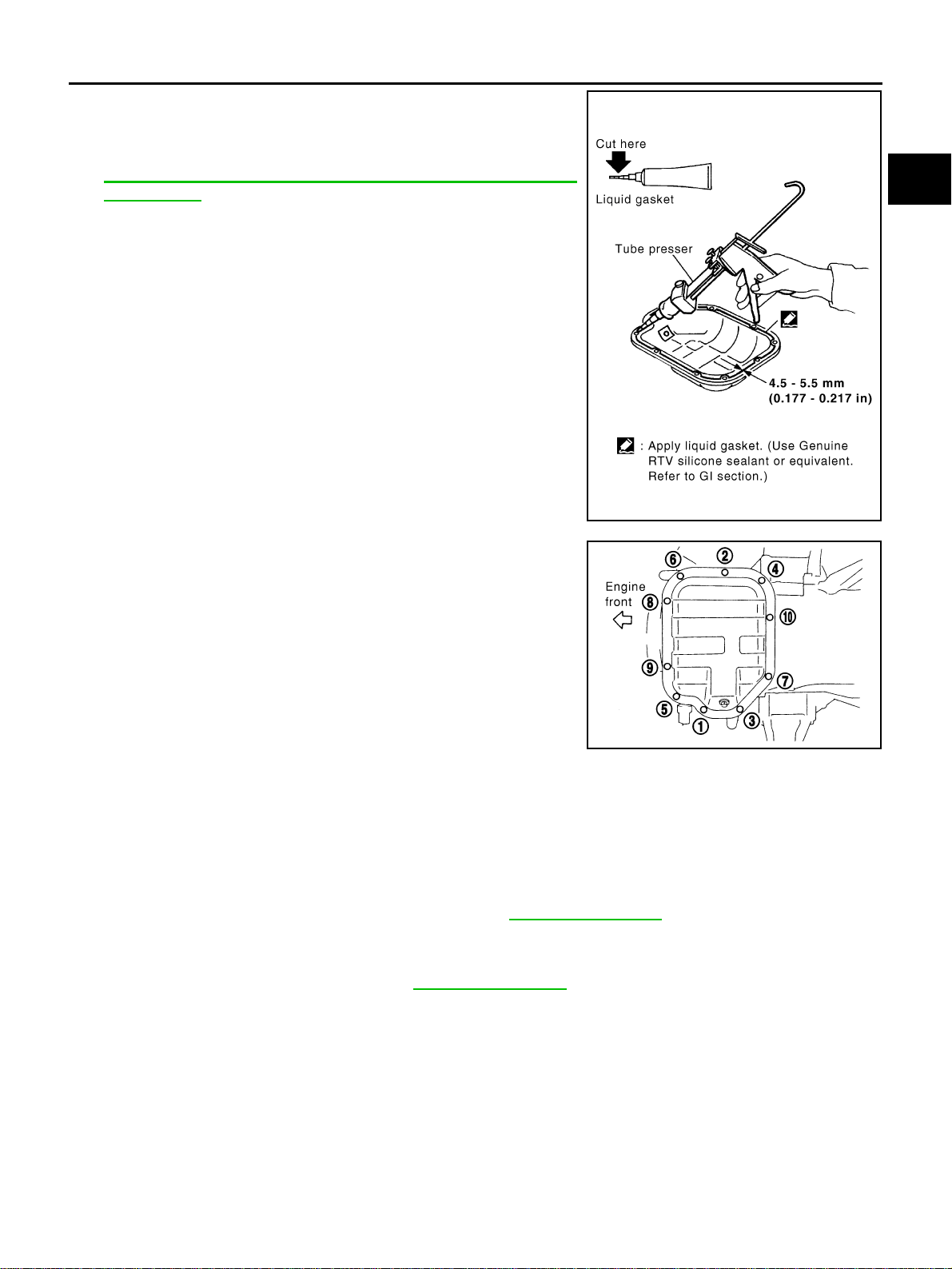
d. Apply a continuous bead of liquid gasket with tube presser [SST:
WS39930000 ( – )] to the cylinder block mating surface of oil
pan (upper) to a limited portion as shown in the figure.
Use Genuine RTV Silicone Sealant or equivalent. Refer to
GI-48, "
RECOMMENDED CHEMICAL PRODUCTS AND
SEALANTS" .
CAUTION:
● For bolt holes with marks (5 locations), apply liquid
gasket outside the holes.
● Apply a bead of 4.5 to 5.5 mm (0.177 to 0.217 in) in diame-
ter to area “A”.
● Attaching should be done within 5 minutes after coating.
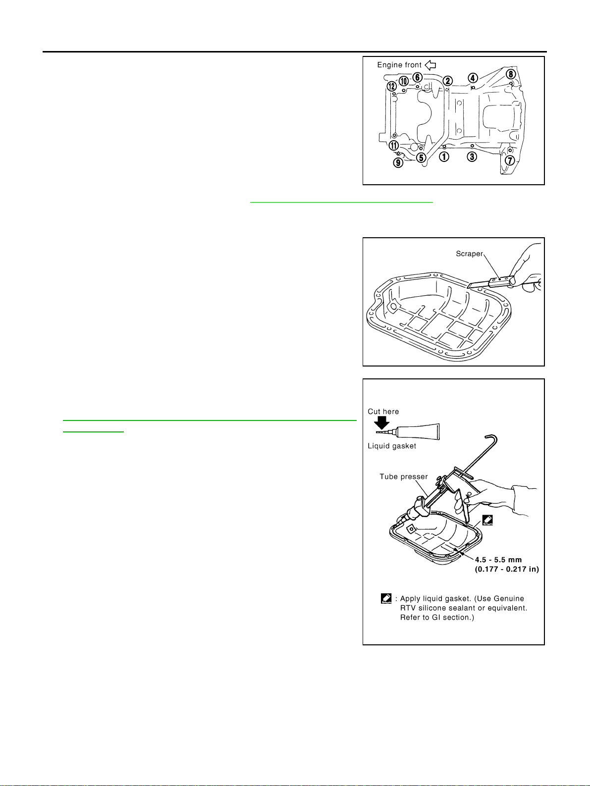
e. Install oil pan (upper).
SEM964E
PBIC1145E
PBIC1144E
PBIC2300E
EM-34
[VQ35DE]
OIL PAN AND OIL STRAINER
Revision: 2004 November 2004 FX35/FX45
● Tighten bolts in numerical order as shown in the figure.
● There are two types of mounting bolts. Refer to the following
for locating bolts.
f. Tighten transmission joint bolts. Refer to AT-266, "
TRANSMISSION ASSEMBLY" .
2. Install oil strainer to oil pump.
3. Install oil pan (lower) as the following:
a. Use scraper to remove old liquid gasket from mating surfaces.
● Also remove old liquid gasket from mating surface of oil
pan (upper).
b. Apply liquid gasket thoroughly with tube presser [SST:
WS39930000 ( – )] as in illustration.
Use Genuine RTV Silicone Sealant or equivalent. Refer to
GI-48, "
RECOMMENDED CHEMICAL PRODUCTS AND
SEALANTS" .
NOTE:
Attaching should be done within 5 minutes after coating.
M8 × 100 mm (3.97 in) : 5, 7, 8, 11
M8 × 25 mm (0.98 in) : Except the above
PBIC0783E
SEM958F
PBIC1146E
OIL PAN AND OIL STRAINER
EM-35
[VQ35DE]
C
D
E
F
G
H
I
J
K
L
M
A
EM
Revision: 2004 November 2004 FX35/FX45
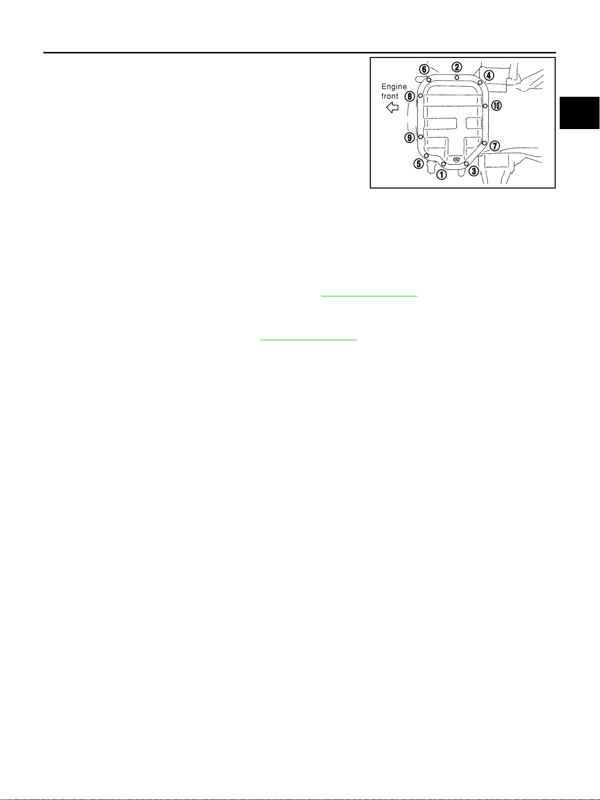
c. Tighten bolts in numerical order as shown in the figure.
4. Install oil pan drain plug.
● Refer to illustration of components of former page for installation direction of washer.
5. Install in the reverse order of removal after this step.
NOTE:
At least 30 minutes after oil pan is installed, pour engine oil.
INSPECTION AFTER INSTALLATION
1. Check the engine oil level and add engine oil. Refer to LU-7, "ENGINE OIL" .
2. Start engine, and check there is no leak of engine oil.
3. Stop engine and wait for 10 minutes.
4. Check the engine oil level again. Refer to LU-7, "
ENGINE OIL" .
PBIC0782E
EM-36
[VQ35DE]
OIL PAN AND OIL STRAINER
Revision: 2004 November 2004 FX35/FX45
AWD MODEL
REMOVAL
CAUTION:
To avoid the danger of being scalded, never drain engine oil when engine is hot.
NOTE:
To remove oil pan (lower) only, take step 5, then step 24. Removal of step 1, hood assembly (step 2) and step
4 are unnecessary.
1. Remove front tire.
2. Remove hood assembly. Refer to BL-14, "
HOOD" .
3. Remove front and rear engine undercover with power tool.
4. Remove front cross bar with power tool. Refer to FSU-6, "
FRONT SUSPENSION ASSEMBLY" .
5. Drain engine oil. Refer to LU-9, "
Changing Engine Oil" .
6. Drain engine coolant. Refer to CO-11, "
Changing Engine Coolant" .
CAUTION:
Perform when engine is cold.
7. Remove engine cover with power tool. Refer to EM-19, "
INTAKE MANIFOLD COLLECTOR" .
1. Oil pan gasket (rear) 2. Oil pan (upper) 3. O-ring
4. Oil pan gasket (front) 5. Oil filter 6. Connector bolt
7. Oil cooler 8. O-ring 9. Relief valve
10. Oil filter bracket 11. Oil filter bracket gasket 12. Oil strainer
13. Drain plug 14. Drain plug washer 15. Oil pan (lower)
16. Rear plate 17. Crankshaft position sensor (POS) 18 O-ring (small)
19. O-ring (large) 20. Axle pipe
SBIA0567E
OIL PAN AND OIL STRAINER
EM-37
[VQ35DE]
C
D
E
F
G
H
I
J
K
L
M
A
EM
Revision: 2004 November 2004 FX35/FX45
8. Remove air hose from air duct to mass air flow sensor side and electric throttle control actuator side.
Refer to EM-17, "
AIR CLEANER AND AIR DUCT" .
9. Remove drive belt for alternator and power steering pump and A/C compressor. Refer to EM-15, "
DRIVE
BELTS" .
10. Remove front drive shaft (LH and RH) and side shaft. Refer to FAX-12, "
FRONT DRIVE SHAFT" .
11. Remove side shaft. Refer to FFD-10, "
FRONT FINAL DRIVE ASSEMBLY" .
12. Removal engine rear lower slinger, and install engine rear slinger to sling engine assembly for positioning.
Refer to EM-8, "
Special Service Tools" .
13. Remove front suspension member. Refer to Refer to FSU-17, "
FRONT SUSPENSION MEMBER" .
14. Remove engine mounting bracket, engine mounting bracket (lower) and insulator. Refer to EM-110,
"ENGINE ASSEMBLY" .
15. Remove front propeller shaft. Refer to PR-4, "
FRONT PROPELLER SHAFT" .
16. Remove oil filter and oil filter bracket. Refer to LU-12, "
OIL FILTER BRACKET (AWD)" .
17. Remove alternator stay. Refer to SC-23, "
CHARGING SYSTEM" .
18. Remove alternator and power steering pump and A/C compressor idler pulley and bracket. Refer to EM-
15, "DRIVE BELTS" .
19. Disconnect A/T fluid cooler hoses, and remove oil cooler water pipe mounting bolt. Refer to LU-14, "
OIL
COOLER" .
20. Disconnect A/T fluid cooler tube.
21. Remove front final drive assembly. Refer to FFD-10, "
FRONT FINAL DRIVE ASSEMBLY" .
22. Remove starter motor. Refer to SC-10, "
STARTING SYSTEM" .
23. Remove crankshaft position sensor (POS).
CAUTION:
● Handle carefully to avoid dropping and shocks.
● Do not disassemble.
● Do not allow metal powder to adhere to magnetic part at sensor tip.
● Do not place sensors in a location where they are exposed to magnetism.
24. Remove oil pan (lower) as the following:
a. Loosen bolts in reverse order as shown in the figure to remove.
b. Insert seal cutter (SST) between oil pan (upper) and oil pan
(lower).
c. Slide seal cutter by tapping on the side of tool with hammer.
Remove oil pan (lower).
CAUTION:
● Be careful not to damage the mating surface.
● Do not insert flat-bladed screwdriver, this will damage the
mating surface.
Slinger bolts:
: 28.0 N·m (2.9 kg-m, 21 ft-lb)
PBIC0782E
SEM960F
EM-38
[VQ35DE]
OIL PAN AND OIL STRAINER
Revision: 2004 November 2004 FX35/FX45
25. Remove oil strainer.
26. Remove transmission joint bolts which pierce oil pan (upper). Refer to AT-266, "
TRANSMISSION ASSEM-
BLY" .
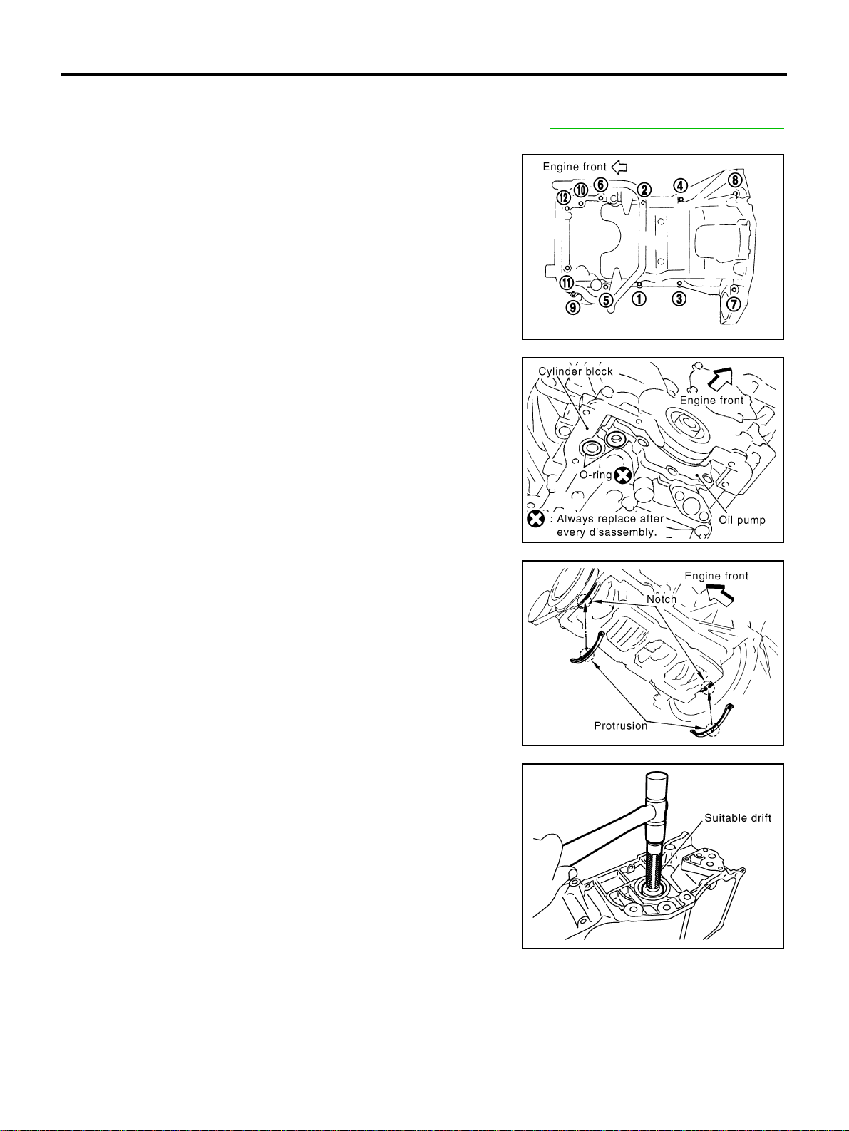
27. Loosen oil pan (upper) bolts with power tool in the reverse order
as shown in the figure to remove.
● Insert seal cutter [SST: KV10111100 (J-37228)] between oil
pan (upper) and cylinder block. Slide seal cutter by tapping on
the side of tool with a hammer. Remove oil pan (upper).
CAUTION:
● Be careful not to damage the mating surface.
● Do not insert a screwdriver, this will damage the mat-
ing surfaces.
28. Remove O-rings from bottom of cylinder block and oil pump.
29. Remove oil pan gaskets.
30. Remove axle pipe, as necessary.
● Remove axle pipe from oil pan (upper) using a suitable drift
[37 mm (1.46 in)].
INSPECTION AFTER REMOVAL
Clean oil strainer if any object attached.
PBIC0783E
PBIC1144E
PBIC1145E
SBIA0469E
OIL PAN AND OIL STRAINER
EM-39
[VQ35DE]
C
D
E
F
G
H
I
J
K
L
M
A
EM
Revision: 2004 November 2004 FX35/FX45
INSTALLATION
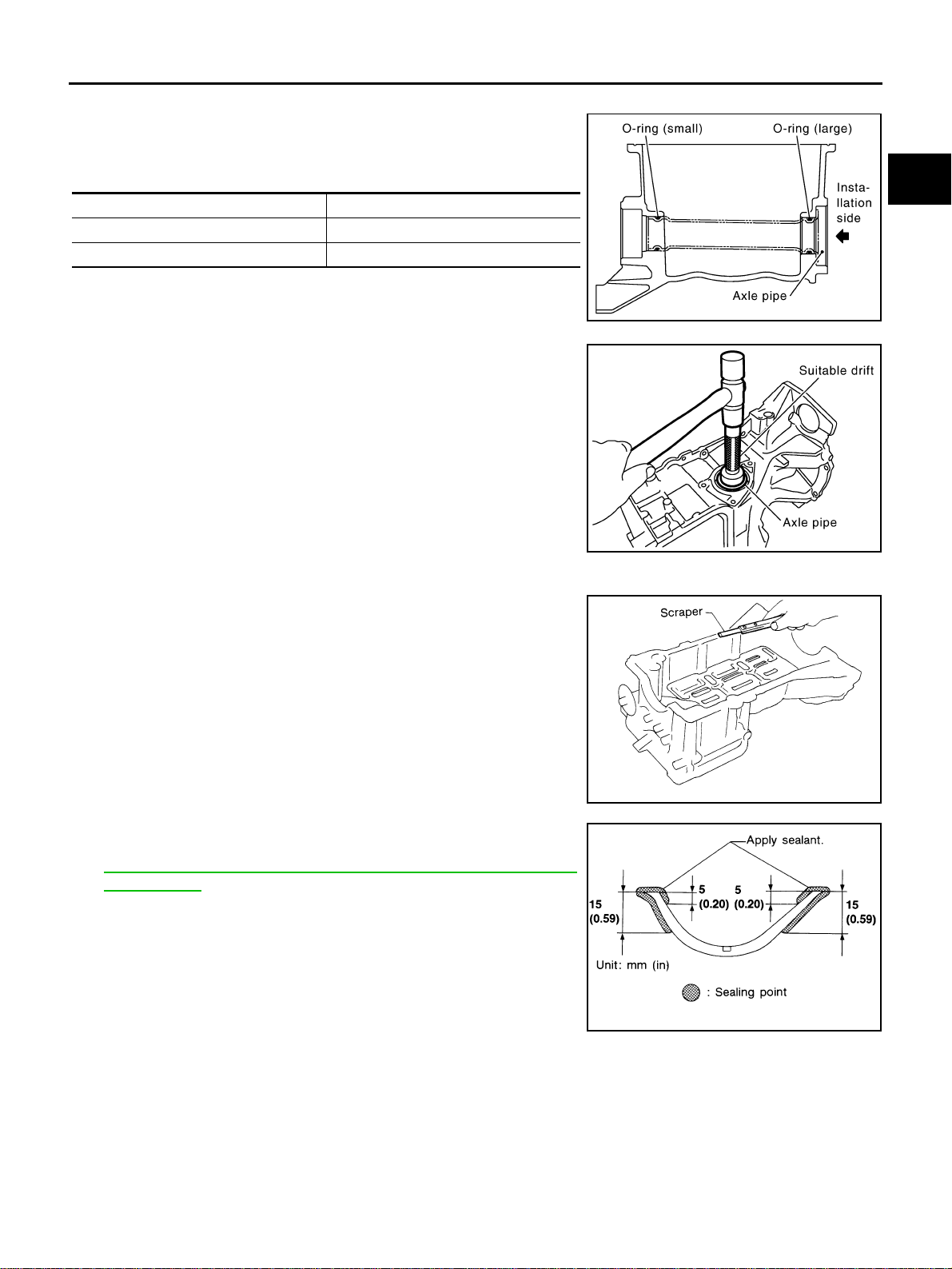
1. Install axle pipe to oil pan, if removed.
● Lubricate O-ring groove of axle pipe, O-ring, and O-ring joint
of oil pan with new engine oil.
Unit: mm (in)
● Install axle pipe to oil pan from axle pipe flange side (LH side)
using a suitable drift [43 - 57 mm (1.69 - 2.24 in)].
CAUTION:
Insert it with care to prevent O-ring from sliding.
2. Install oil pan (upper) as the following:
a. Use scraper to remove old liquid gasket from mating surfaces.
CAUTION:
Do not scratch or damage the mating surfaces when clean-
ing off old liquid gasket.
● Also remove old liquid gasket from mating surface of cylinder
block.
● Remove old liquid gasket from the bolt holes and threads.
b. Apply liquid gasket to oil pan gaskets as shown in the figure.
Use Genuine RTV Silicone Sealant or equivalent. Refer to
GI-48, "
RECOMMENDED CHEMICAL PRODUCTS AND
SEALANTS" .
Item O-ring inner diameter
Final drive side (RH side) 32 (1.26)
Axle pipe flange side (LH side) 34 (1.34)
SBIA0470E
SBIA0471E
MEM108A
SEM964E
EM-40
[VQ35DE]
OIL PAN AND OIL STRAINER
Revision: 2004 November 2004 FX35/FX45
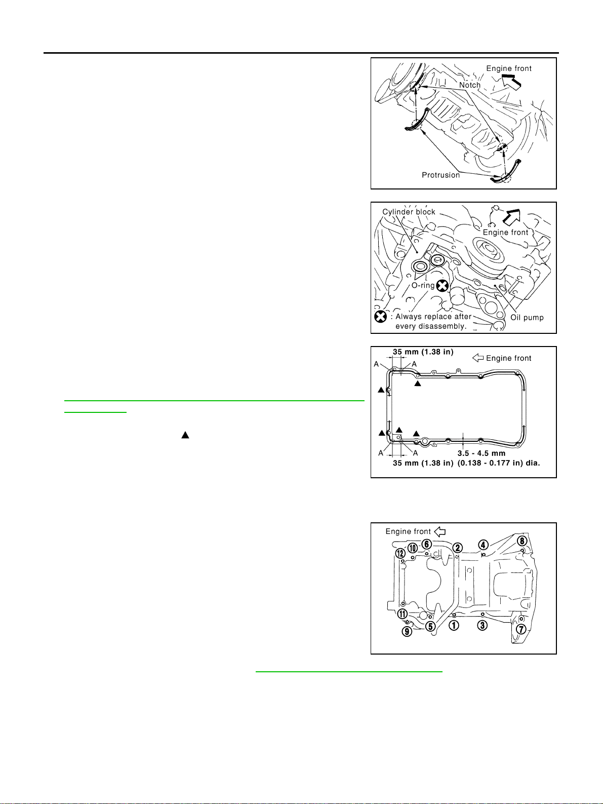
● To install, align protrusion of oil pan gasket with notches of
front timing chain case and rear oil seal retainer.
● Install oil pan gasket with smaller arc to front timing chain
case side.
c. Install new O-rings on cylinder block and oil pump side.
d. Apply a continuous bead of liquid gasket with tube presser [SST:
WS39930000 ( – )] to the cylinder block mating surface of oil
pan (upper) to a limited portion as shown in the figure.
Use Genuine RTV Silicone Sealant or equivalent. Refer to
GI-48, "
RECOMMENDED CHEMICAL PRODUCTS AND
SEALANTS" .
CAUTION:
● For bolt holes with marks (5 locations), apply liquid
gasket outside the holes.
● Apply a bead of 4.5 to 5.5 mm (0.177 to 0.217 in) in diame-
ter to area “A”.
● Attaching should be done within 5 minutes after coating.
e. Install oil pan (upper).
● Tighten bolts in numerical order as shown in the figure.
● There are two types of mounting bolts. Refer to the following
for locating bolts.
f. Tighten transmission joint bolts. Refer to AT-266, "
TRANSMISSION ASSEMBLY" .
3. Install oil strainer to oil pump.
PBIC1145E
PBIC1144E
PBIC2300E
M8 × 100 mm (3.97 in) : 5, 7, 8, 11
M8 × 25 mm (0.98 in) : Except the above
PBIC0783E
OIL PAN AND OIL STRAINER
EM-41
[VQ35DE]
C
D
E
F
G
H
I
J
K
L
M
A
EM
Revision: 2004 November 2004 FX35/FX45
4. Install oil pan (lower) in the order below.
a. Apply liquid gasket thoroughly with tube presser [SST:
WS39930000 ( – )] as in illustration.
Use Genuine RTV Silicone Sealant or equivalent. Refer to
GI-48, "
RECOMMENDED CHEMICAL PRODUCTS AND
SEALANTS" .
NOTE:
Attaching should be done within 5 minutes after coating.
b. Tighten bolts in numerical order as shown in the figure.
5. Install oil pan drain plug.
● Refer to illustration of components of former page for installation direction of washer.
6. Install in the reverse order of removal after this step.
NOTE:
At least 30 minutes after oil pan is installed, pour engine oil.
INSPECTION AFTER INSTALLATION
1. Check the engine oil level and add engine oil. Refer to LU-7, "ENGINE OIL" .
2. Start engine, and check there is no leak of engine oil.
3. Stop engine and wait for 10 minutes.
4. Check the engine oil level again. Refer to LU-7, "
ENGINE OIL" .
PBIC1146E
PBIC0782E
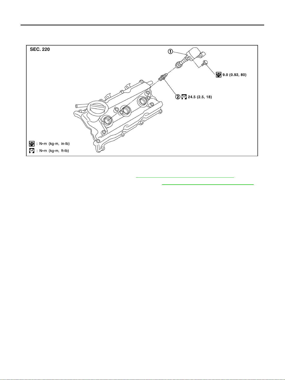
EM-42
[VQ35DE]
IGNITION COIL
Revision: 2004 November 2004 FX35/FX45
IGNITION COIL PFP:22448
Removal and Installation ABS004U6
REMOVAL
1. Remove engine cover with power tool. Refer to EM-19, "INTAKE MANIFOLD COLLECTOR" .
2. Remove air duct (for ignition coil of left bank side). Refer to EM-17, "
AIR CLEANER AND AIR DUCT" .
3. Move aside harness, harness bracket, and hoses located above ignition coil.
4. Disconnect harness connector from ignition coil.
5. Remove ignition coil.
CAUTION:
Do not shock it.
INSTALLATION
Install in the reverse order of removal.
1. Ignition coil 2. Spark plug
SBIA0568E
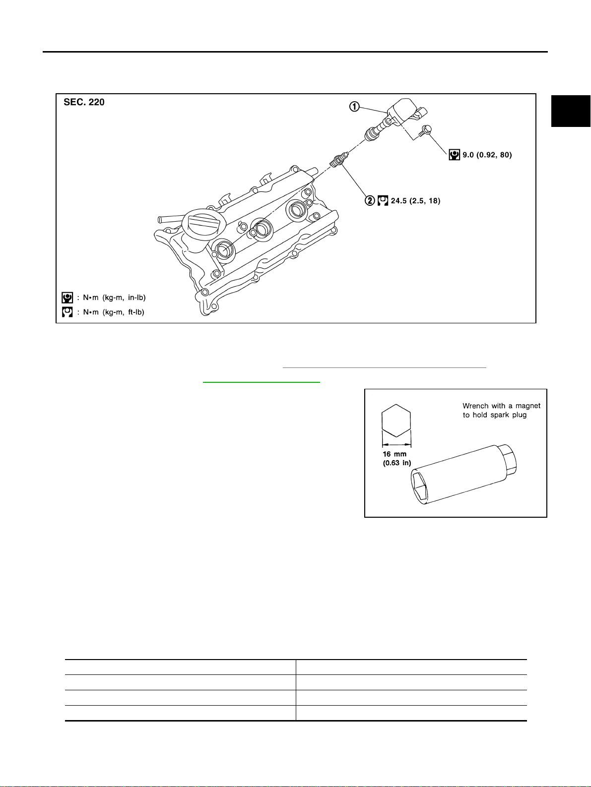
SPARK PLUG (PLATINUM-TIPPED TYPE)
EM-43
[VQ35DE]
C
D
E
F
G
H
I
J
K
L
M
A
EM
Revision: 2004 November 2004 FX35/FX45
SPARK PLUG (PLATINUM-TIPPED TYPE) PFP:22401
Removal and Installation ABS004WI
REMOVAL
1. Remove engine cover with power tool. Refer to EM-19, "INTAKE MANIFOLD COLLECTOR" .
2. Remove ignition coil. Refer to EM-42, "
IGNITION COIL" .
3. Remove spark plug with spark plug wrench (commercial service
tool).
INSPECTION AFTER REMOVAL
Use standard type spark plug for normal condition.
The hot type spark plug is suitable when fouling occurs with the standard type spark plug under conditions
such as:
● Frequent engine starts
● Low ambient temperatures
The cold type spark plug is suitable when spark knock occurs with the standard type spark plug under condi-
tions such as:
● Extended highway driving
● Frequent high engine revolution
1. Ignition coil 2. Spark plug
SBIA0568E
SEM294A
Make NGK
Standard type PLFR5A-11
Hot type PLFR4A-11
Cold type PLFR6A-11
Gap (Nominal) : 1.1 mm (0.043 in)
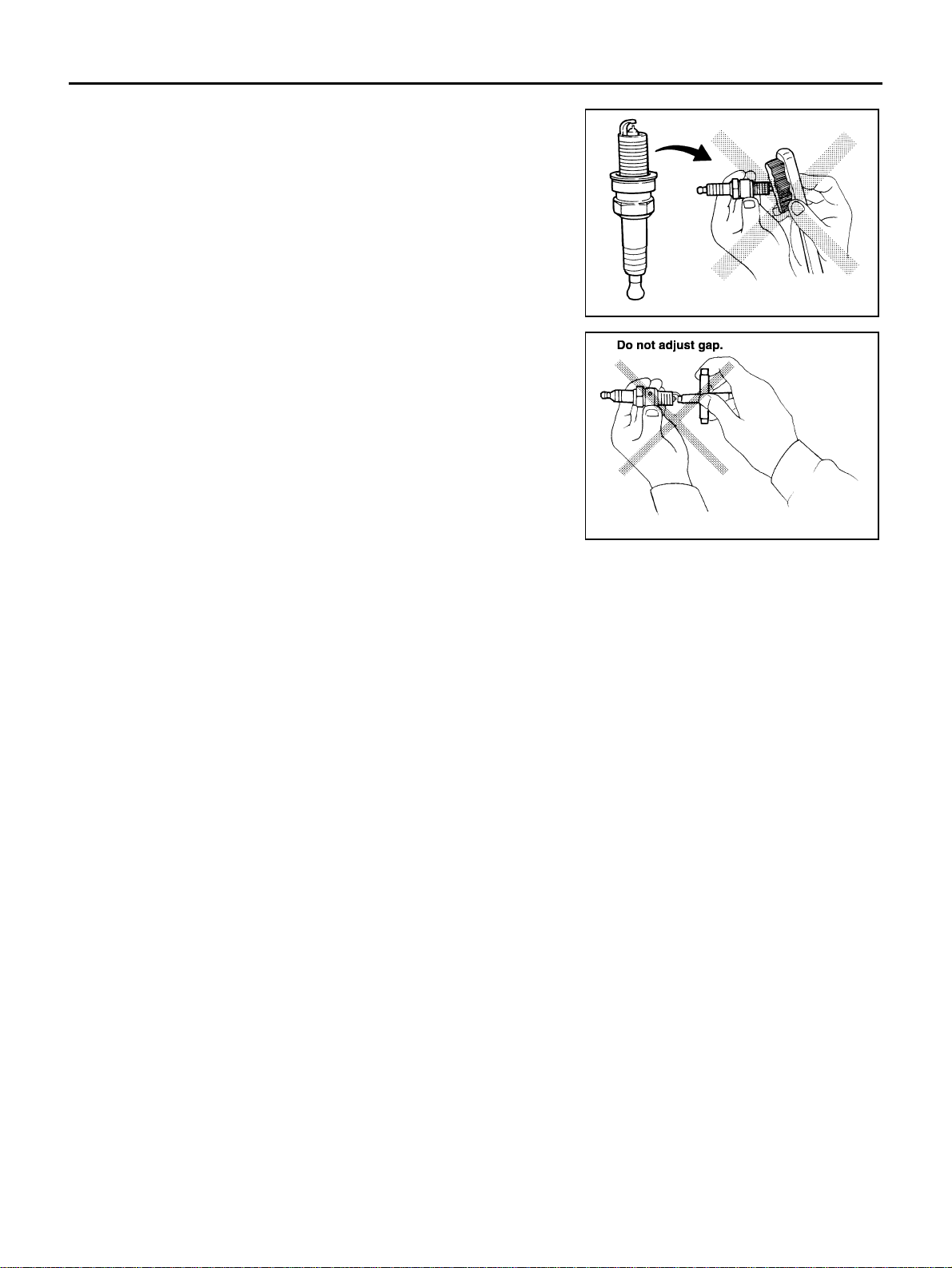
EM-44
[VQ35DE]
SPARK PLUG (PLATINUM-TIPPED TYPE)
Revision: 2004 November 2004 FX35/FX45
CAUTION:
● Do not drop or shock spark plug.
● Do not use a wire brush for cleaning.
● If plug tip is covered with carbon, spark plug cleaner may
be used.
● Checking and adjusting plug gap is not required between
change intervals.
INSTALLATION
Install in the reverse order of removal.
Cleaner air pressure:
Less than 588 kPa (6 kg/cm
2
, 85 psi)
Cleaning time:
Less than 20 seconds
SMA773C
SMA806CA
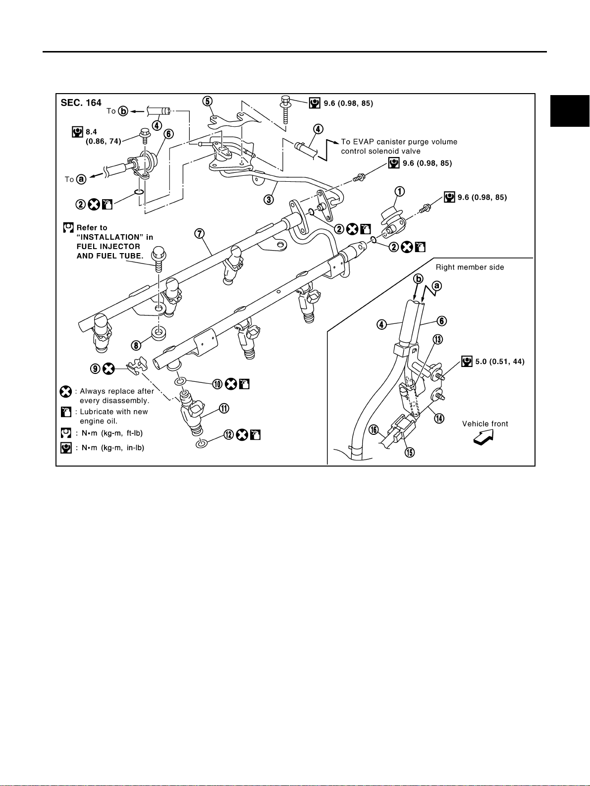
FUEL INJECTOR AND FUEL TUBE
EM-45
[VQ35DE]
C
D
E
F
G
H
I
J
K
L
M
A
EM
Revision: 2004 November 2004 FX35/FX45
FUEL INJECTOR AND FUEL TUBE PFP:16600
Removal and Installation ABS004U8
CAUTION:
Do not remove or disassemble parts unless instructed as shown in the figure.
1. Fuel damper 2. O-ring 3. Fuel sub-tube
4. EVAP hose 5. Intake manifold collector (lower) 6. Fuel feed hose (with damper)
7. Fuel tube 8. Spacer 9. Clip
10. O-ring (blue) 11. Fuel injector 12. O-ring (brown)
13. Hose clamp 14. Bracket 15. Quick connector cap
16. Centralized under-floor piping
SBIA0580E
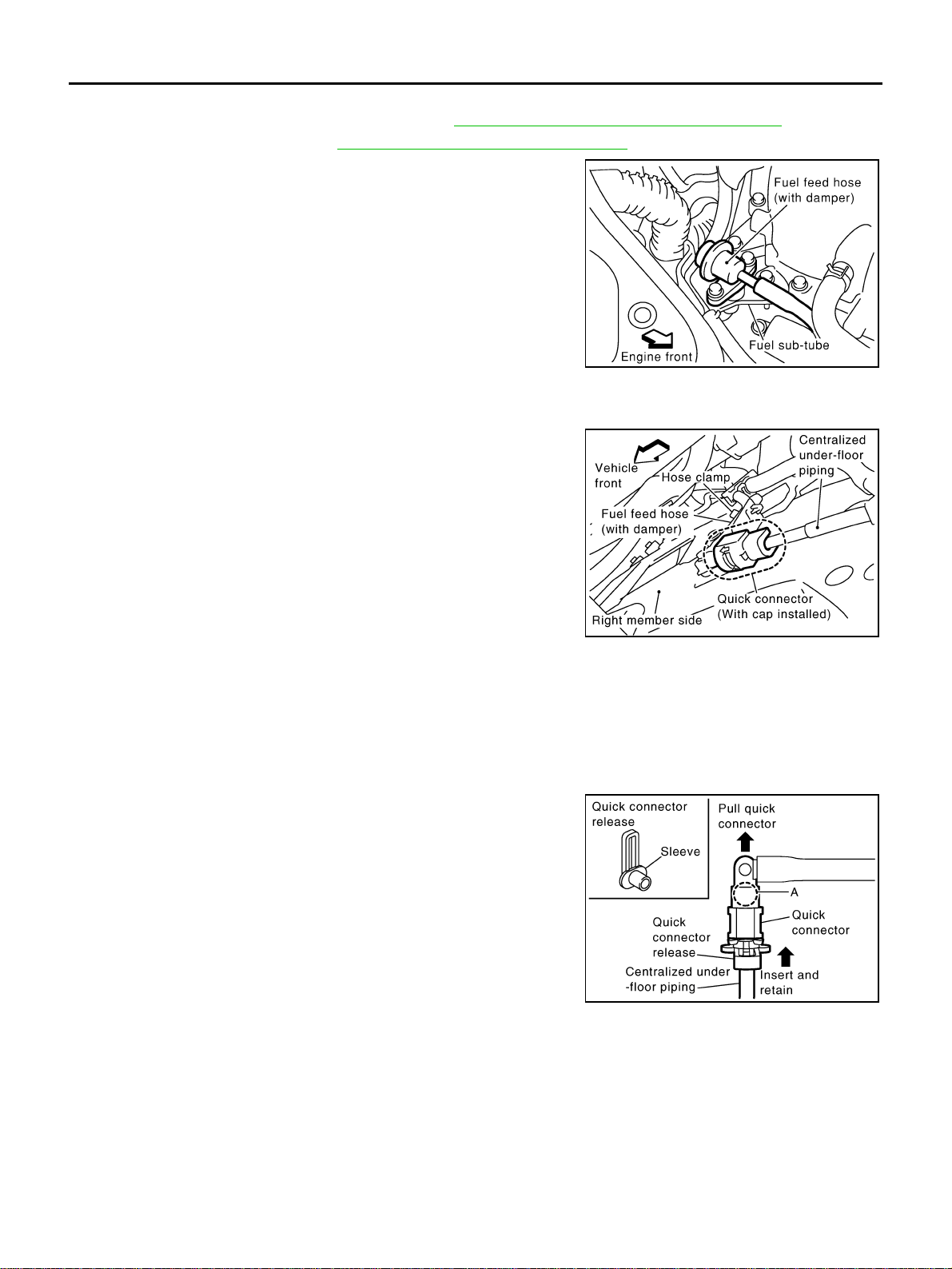
EM-46
[VQ35DE]
FUEL INJECTOR AND FUEL TUBE
Revision: 2004 November 2004 FX35/FX45
REMOVAL
1. Remove engine cover with power tool. Refer to EM-19, "INTAKE MANIFOLD COLLECTOR" .
2. Release fuel pressure. Refer to EC-51, "
FUEL PRESSURE RELEASE" .
3. Remove fuel feed hose (with damper) from fuel sub-tube.
NOTE:
There is no fuel return route.
CAUTION:
● While hoses are disconnected, plug them to prevent fuel
from draining.
● Do not separate damper and hose.
4. When separating fuel feed hose (with damper) and centralized under-floor piping connection, disconnect
quick connector as the following:
a. Remove quick connector cap from quick connector connection
on right member side.
b. Disconnect fuel feed hose (with damper) from bracket hose
clamp.
c. Disconnect quick connector from centralized under-floor piping as the following:
CAUTION:
Disconnect quick connector by using quick connector release [SST: — (J-45488)], not by picking
out retainer tabs.
i. With the sleeve side of quick connector release facing quick connector, install quick connector release
onto centralized under-floor piping.
ii. Insert quick connector release into quick connector until sleeve
contacts and goes no further. Hold quick connector release on
that position.
CAUTION:
Inserting quick connector release hard will not disconnect
quick connector. Hold quick connector release where it
contacts and goes no further.
iii. Draw and pull out quick connector straight from centralized
under-floor piping.
CAUTION:
● Pull quick connector holding “A” position as shown in
the figure.
● Do not pull with lateral force applied. O-ring inside quick connector may be damaged.
● Prepare container and cloth beforehand as fuel will leak out.
● Avoid fire and sparks.
● Keep parts away from heat source. Especially, be careful when welding is performed around
them.
● Do not expose parts to battery electrolyte or other acids.
● Do not bend or twist connection between quick connector and fuel feed hose (with damper) dur-
ing installation/removal.
KBIA1293E
PBIC2083E
PBIC1898E
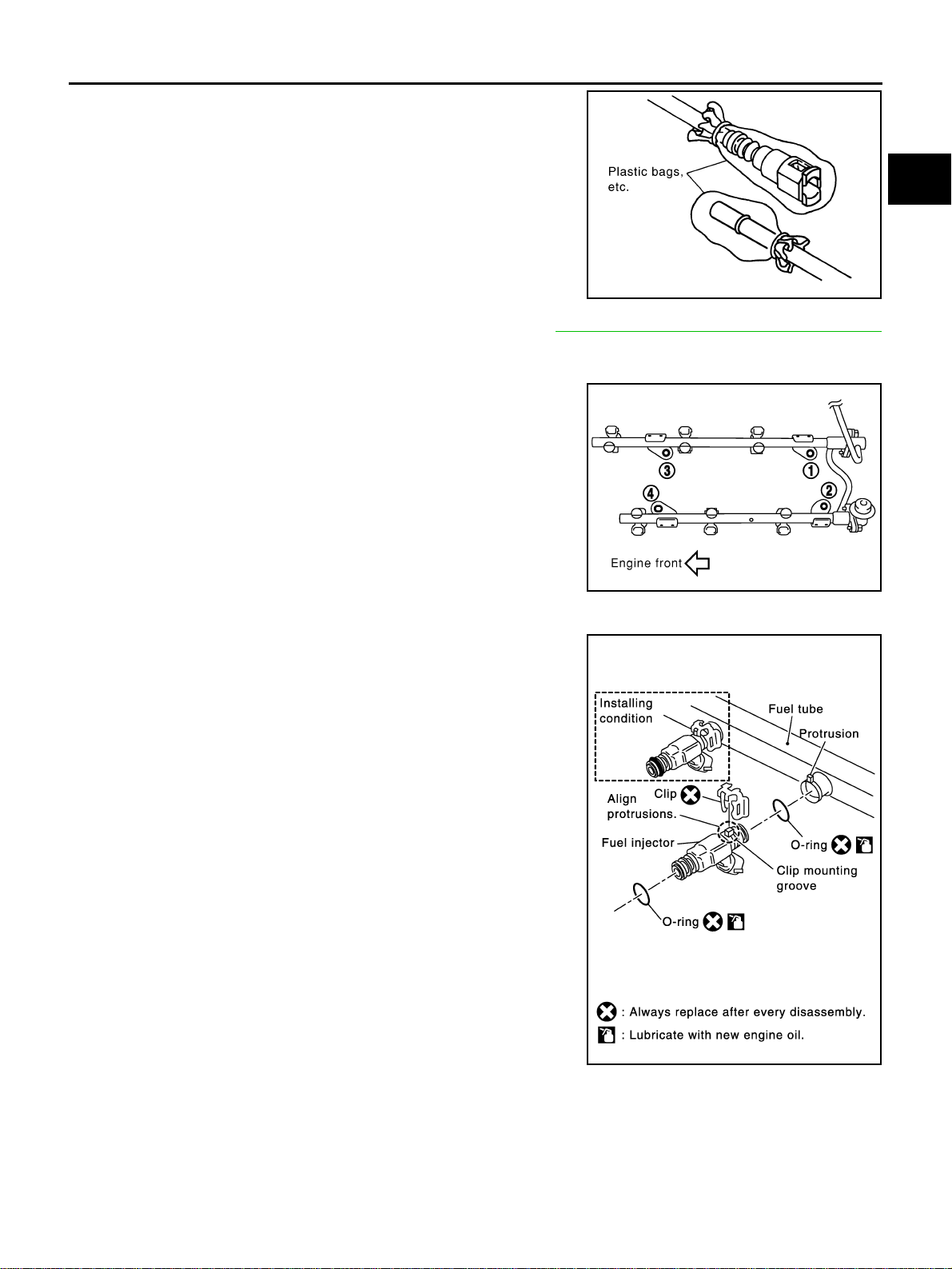
FUEL INJECTOR AND FUEL TUBE
EM-47
[VQ35DE]
C
D
E
F
G
H
I
J
K
L
M
A
EM
Revision: 2004 November 2004 FX35/FX45
● To keep clean the connecting portion and to avoid dam-
age and foreign materials, cover them completely with
plastic bags or something similar.
5. Remove intake manifold collector (upper and lower). Refer to EM-19, "
INTAKE MANIFOLD COLLECTOR"
.
6. Disconnect harness connector from fuel injector.
7. Loosen mounting bolts in the reverse order in the figure, and
remove fuel tube and fuel injector assembly.
CAUTION:
Do not tilt it, or remaining fuel in pipes may flow out from
pipes.
8. Remove spacers on intake manifold.
9. Remove fuel injector from fuel tube with following procedure.
a. Open and remove clip.
b. Remove fuel injector from fuel tube by pulling straight.
CAUTION:
● Be careful with remaining fuel that may go out from fuel
tube.
● Be careful not to damage injector nozzles during
removal.
● Do not bump or drop fuel injectors.
● Do not disassemble fuel injectors.
10. Remove fuel sub-tube and fuel damper.
INSTALLATION
1. Install fuel damper and fuel sub-tube.
● When handling O-rings, be careful of the following:
CAUTION:
● Handle O-ring with bare hands. Never wear gloves.
PBIC1899E
KBIA1296E
SBIA0364E
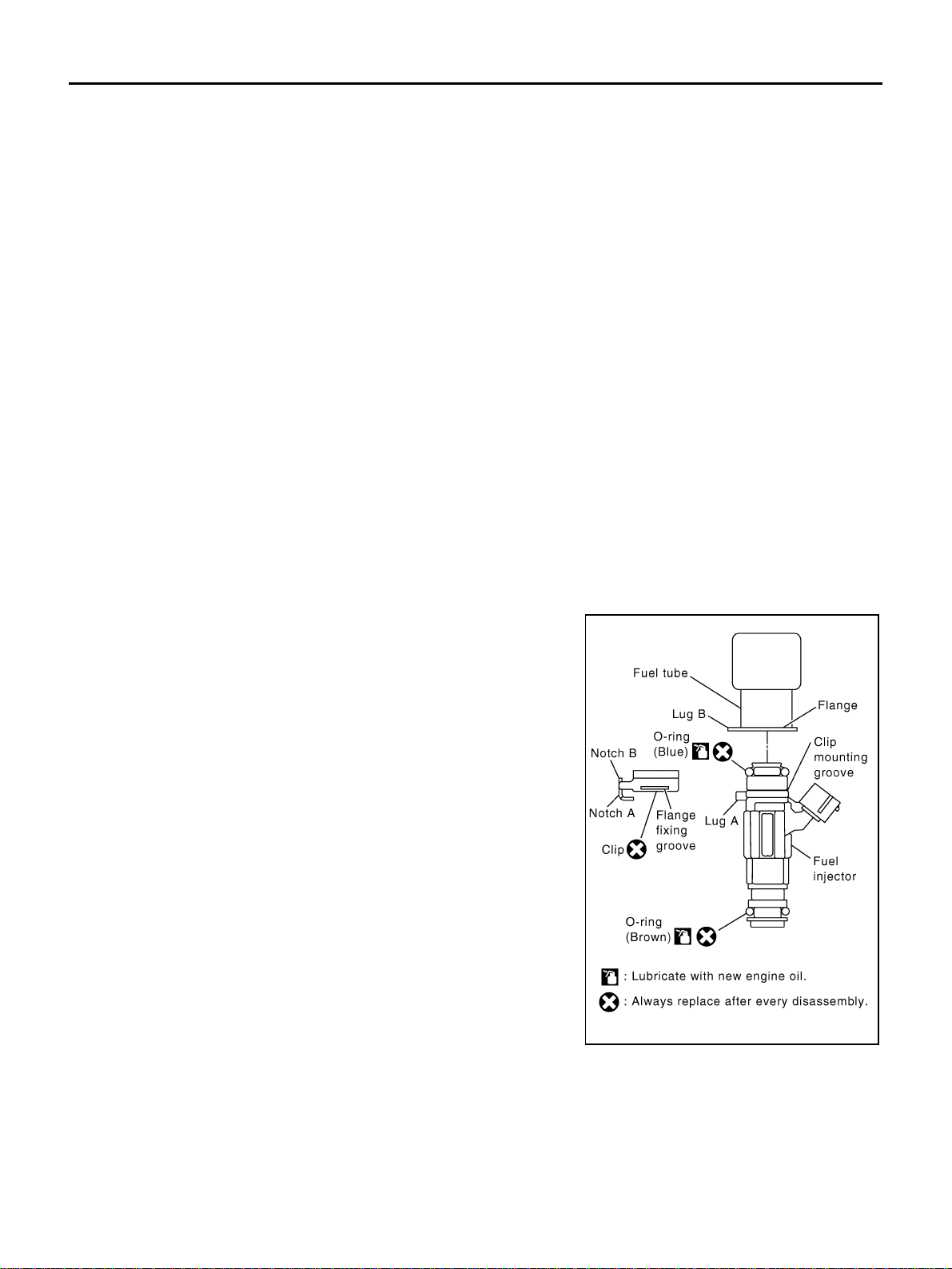
EM-48
[VQ35DE]
FUEL INJECTOR AND FUEL TUBE
Revision: 2004 November 2004 FX35/FX45
● Lubricate O-ring with new engine oil.
● Do not clean O-ring with solvent.
● Make sure that O-ring and its mating part are free of foreign material.
● When installing O-ring, be careful not to scratch it with tool or fingernails. Also be careful not
to twist or stretch O-ring. If O-ring was stretched while it was being attached, do not insert it
quickly into fuel tube.
● Insert O-ring straight into fuel tube. Do not decenter or twist it.
● Insert fuel damper and fuel sub-tube straight into fuel tube.
● Tighten mounting bolts evenly in turn.
● After tightening mounting bolts, make sure that there is no gap between flange and fuel tube.
2. Install O-rings to fuel injector paying attention to the items below.
CAUTION:
● Upper and lower O-ring are different. Be careful not to confuse them.
● Handle O-ring with bare hands. Never wear gloves.
● Lubricate O-ring with new engine oil.
● Do not clean O-ring with solvent.
● Make sure that O-ring and its mating part are free of foreign material.
● When installing O-ring, be careful not to scratch it with tool or fingernails. Also be careful not to
twist or stretch O-ring. If O-ring was stretched while it was being attached, do not insert it
quickly into fuel tube.
● Insert O-ring straight into fuel tube. Do not decenter or twist it.
3. Install fuel injector to fuel tube with the following procedure.
a. Insert clip into clip mounting groove on fuel injector.
● Insert clip so that lug “A” of fuel injector matches notch “A” of
clip.
CAUTION:
● Do not reuse clip. Replace it with a new one.
● Be careful to keep clip from interfering with O-ring. If
interference occurs, replace O-ring.
b. Insert fuel injector into fuel tube with clip attached.
● Insert it while matching it to the axial center.
● Insert fuel injector so that lug “B” of fuel tube matches notch
“B” of clip.
● Make sure that fuel tube flange is securely fixed in flange fix-
ing groove on clip.
c. Make sure that installation is complete by checking that fuel
injector does not rotate or come off.
4. Install spacers on intake manifold.
Fuel tube side : Blue
Nozzle side : Brown
PBIC1931E
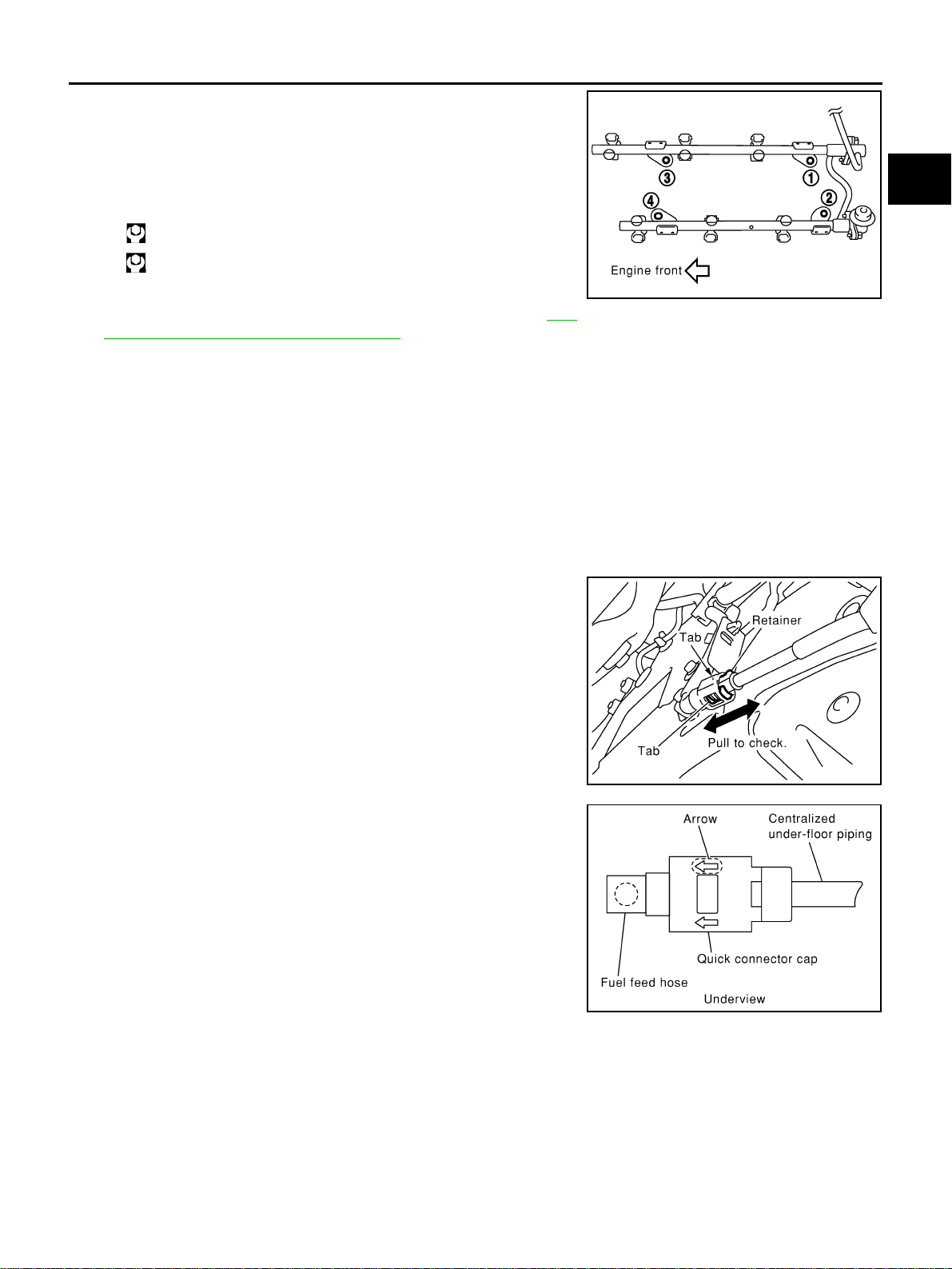
FUEL INJECTOR AND FUEL TUBE
EM-49
[VQ35DE]
C
D
E
F
G
H
I
J
K
L
M
A
EM
Revision: 2004 November 2004 FX35/FX45
5. Install fuel tube and fuel injector assembly to intake manifold.
CAUTION:
Be careful not to let tip of injector nozzle come in contact
with other parts.
● Tighten mounting bolts in two steps in numerical order shown
in figure.
6. Connect injector sub-harness.
7. Install intake manifold collector (upper and lower). Refer to EM-
19, "INTAKE MANIFOLD COLLECTOR" .
8. Install fuel sub-tube on rear end of intake manifold collector (lower).
9. Connect fuel feed hose (with damper).
● Handling procedure of O-ring is the same as that of fuel damper and fuel sub-tube.
● Insert fuel damper straight into fuel sub-tube.
● Tighten mounting bolts evenly in turn.
● After tightening mounting bolts, make sure that there is no gap between flange and fuel sub-tube.
10. Connect quick connector between fuel feed hose and centralized under-floor piping connection with the
following procedure:
a. Check the connection for damage and foreign materials.
b. Align connector with tube, then insert connector straight into tube until a click is heard.
c. After connecting quick connector, use the following method to
make sure it is full connected.
● Visually confirm that the two retainer tabs are connected to
connector.
● Pull tube and connector to make sure they are securely con-
nected.
d. Install quick connector cap to quick connector connection.
● Install quick connector cap with arrow on surface facing in
direction of quick connector (fuel feed hose side).
CAUTION:
If cap cannot be installed smoothly, quick connector may
have not been installed correctly. Check connection
again.
e. Secure fuel feed hose to clamp.
11. Install in the reverse order of removal after this step.
INSPECTION AFTER INSTALLATION
Check on Fuel Leakage
● After installing fuel tubes, make sure there is no fuel leakage at connections in the following steps.
– a) Apply fuel pressure to fuel lines with turning ignition switch “ON” (with engine stopped). Then check for
fuel leaks at connections.
– b) Start engine and rev it up and check for fuel leaks at connections.
NOTE:
Use mirrors for checking on invisible points.
1st step: 10.1 N·m (1.0 kg-m, 7 ft-lb)
2nd step: 23.6 N·m (2.4 kg-m, 17 ft-lb)
KBIA1296E
KBIA1297E
KBIA1298E

EM-50
[VQ35DE]
FUEL INJECTOR AND FUEL TUBE
Revision: 2004 November 2004 FX35/FX45
CAUTION:
Do not touch engine immediately after stopped, as engine becomes extremely hot.
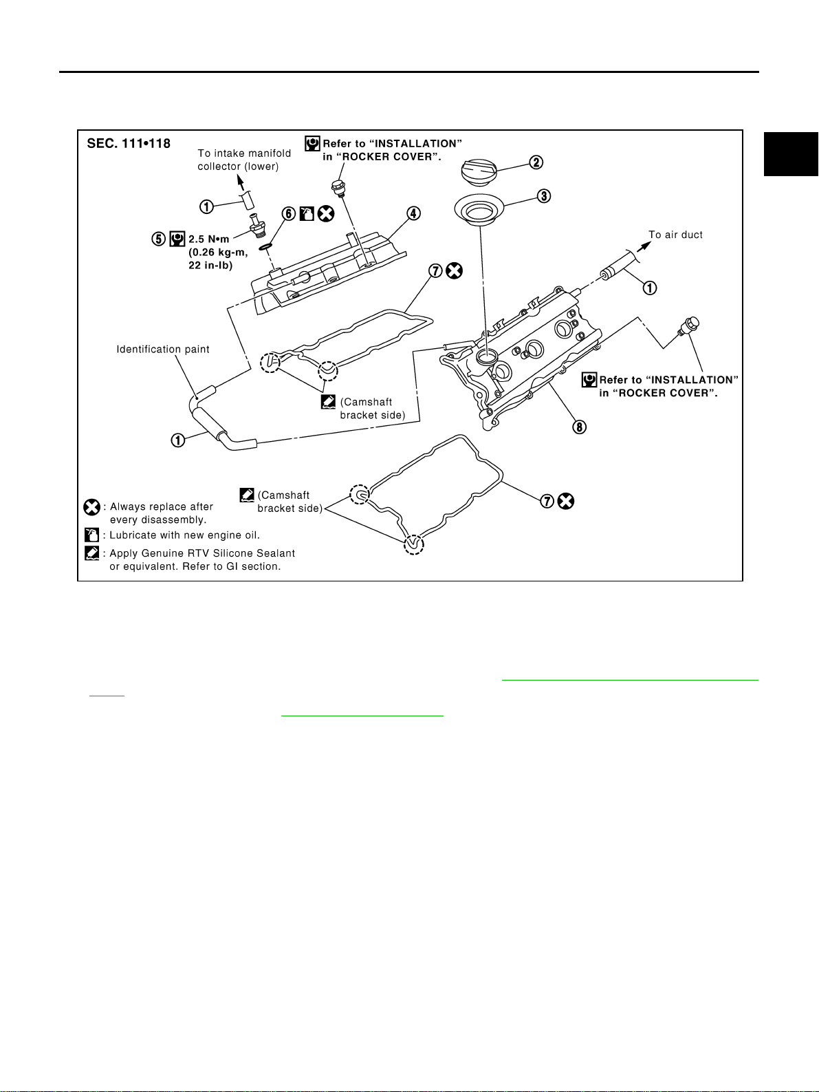
ROCKER COVER
EM-51
[VQ35DE]
C
D
E
F
G
H
I
J
K
L
M
A
EM
Revision: 2004 November 2004 FX35/FX45
ROCKER COVER PFP:13264
Removal and Installation ABS004U9
REMOVAL
1. Remove intake manifold collectors (upper and lower). Refer to EM-19, "INTAKE MANIFOLD COLLEC-
TOR" .
2. Remove ignition coil. Refer to EM-42, "
IGNITION COIL" .
3. Remove PCV hoses from rocker covers.
4. Remove PCV valve and O-ring from rocker cover (right bank), if necessary.
5. Remove oil filler cap from rocker cover (left bank), if necessary.
1. PCV hose 2. Oil filler cap 3. Oil catcher
4. Rocker cover (right bank) 5. PCV control valve 6. O-ring
7. Rocker cover gasket 8. Rocker cover (left bank)
PBIC2303E
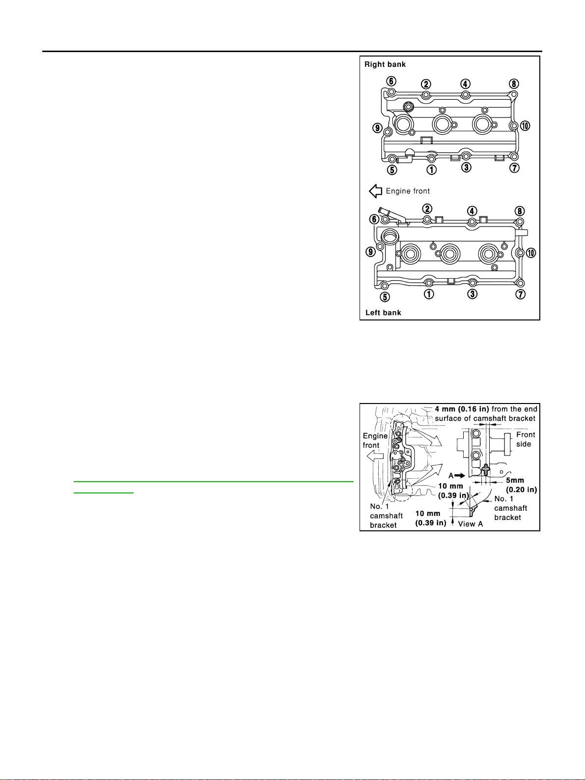
EM-52
[VQ35DE]
ROCKER COVER
Revision: 2004 November 2004 FX35/FX45
6. Loosen bolts in the reverse order shown in the figure (with
power tool).
7. Remove rocker cover gaskets from rocker covers.
8. Use scraper to remove all trances of liquid gasket from cylinder head and camshaft bracket (No. 1).
CAUTION:
Do not scratch or damage the mating surface when cleaning off old liquid gasket.
INSTALLATION
1. Apply liquid gasket of 3.0 mm (0.12 in) diameter to position
shown in the figure (both edges of No. 1 camshaft bracket) (on
both banks).
● First, apply it to engine longitudinal direction [5.0 mm (0.197
in) + 5.0 mm (0.197 in) side in figure].
Use Genuine RTV Silicone Sealant or equivalent. Refer to
GI-48, "
RECOMMENDED CHEMICAL PRODUCTS AND
SEALANTS" .
2. Install new rocker cover gasket to rocker cover.
3. Install rocker cover.
● Check if rocker cover gasket is dropped from installation groove of rocker cover.
KBIA0985E
PBIC0786E
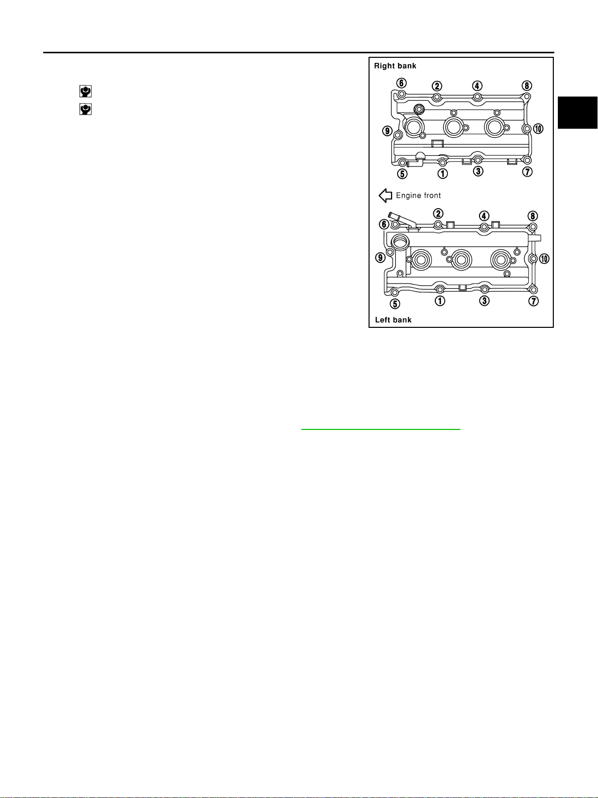
ROCKER COVER
EM-53
[VQ35DE]
C
D
E
F
G
H
I
J
K
L
M
A
EM
Revision: 2004 November 2004 FX35/FX45
4. Tighten bolts two steps separately in order numbers in illustra-
tion.
5. Install oil filer cap to rocker cover (left bank), if removed.
6. Install new O-ring and PCV valve to rocker cover (right bank), if removed.
7. Install PCV hose.
● Insert PCV hose by 25 to 30 mm (0.98 to 1.18 in) from connector end.
● When installing, be careful not to twist or come in contact with other parts.
● Install PCV hose between right and left rocker covers with its identification paint facing upward (right
rocker cover side). Refer to component figure in EM-51, "
Removal and Installation" .
8. Install in the reverse order of removal after this step.
1st step: 1.96 N·m (0.20 kg-m, 17 in-lb)
2nd step: 8.33 N·m (0.85 kg-m, 74 in-lb)
KBIA0985E
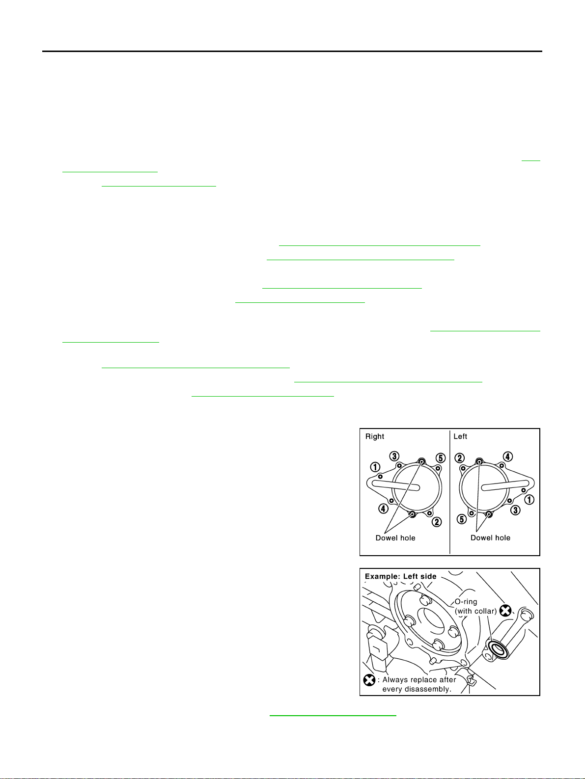
EM-54
[VQ35DE]
FRONT TIMING CHAIN CASE
Revision: 2004 November 2004 FX35/FX45
FRONT TIMING CHAIN CASE PFP:13599
Removal and Installation ABS004X0
NOTE:
● This section describes removal/installation procedure of front timing chain case and timing chain related
parts without removing oil pan (upper) on vehicle.
● When oil pan (upper) needs to be removed or installed, or when rear timing chain case is removed or
installed, remove oil pans (upper and lower) first. Then remove front timing chain case, timing chain
related parts, and rear timing chain case in this order, and install in reverse order of removal. Refer to EM-
63, "TIMING CHAIN" .
● Refer to EM-63, "TIMING CHAIN" for component parts location.
REMOVAL
1. Place vehicle onto lift.
2. Disconnect negative battery terminal.
3. Remove engine cover with power tool. Refer to EM-19, "
INTAKE MANIFOLD COLLECTOR" .
4. Remove air cleaner case assembly. Refer to EM-17, "
AIR CLEANER AND AIR DUCT" .
5. Remove front and rear engine undercover with power tool.
6. Drain engine coolant from radiator. Refer to CO-11, "
Changing Engine Coolant" .
7. Drain engine oil from oil pan. Refer to LU-9, "
Changing Engine Oil" .
8. Remove engine harnesses.
9. Remove intake manifold collectors (upper and lower) with power tool. Refer to EM-19, "
INTAKE MANI-
FOLD COLLECTOR" .
10. Remove power steering oil pump from bracket with piping connected, and temporarily secure it aside.
Refer to PS-31, "
POWER STEERING OIL PUMP" .
11. Remove power steering oil pump bracket. Refer to PS-31, "
POWER STEERING OIL PUMP" .
12. Remove alternator. Refer to SC-23, "
CHARGING SYSTEM" .
13. Remove water bypass hose, water hose clamp and idler pulley bracket and alternator and power steering
oil pump and A/C compressor belt tensioner from front timing chain case.
14. Remove right and left intake valve timing control covers with
power tool.
● Loosen bolts in reverse order as shown in the figure.
● Use seal cutter [SST: KV10111100 (J-37228)] or an equivalent
tool to cut liquid gasket for removal.
CAUTION:
Shaft is internally jointed with intake camshaft sprocket
center hole. When removing, keep it horizontal until it is
completely disconnected.
15. Remove collared O-rings from front timing chain case (left and
right side).
16. Remove right and left rocker covers. Refer to EM-51, "
ROCKER COVER" .
NOTE:
When secondary timing chain is not removed/installed, this step is not required.
SEM728G
PBIC2045E
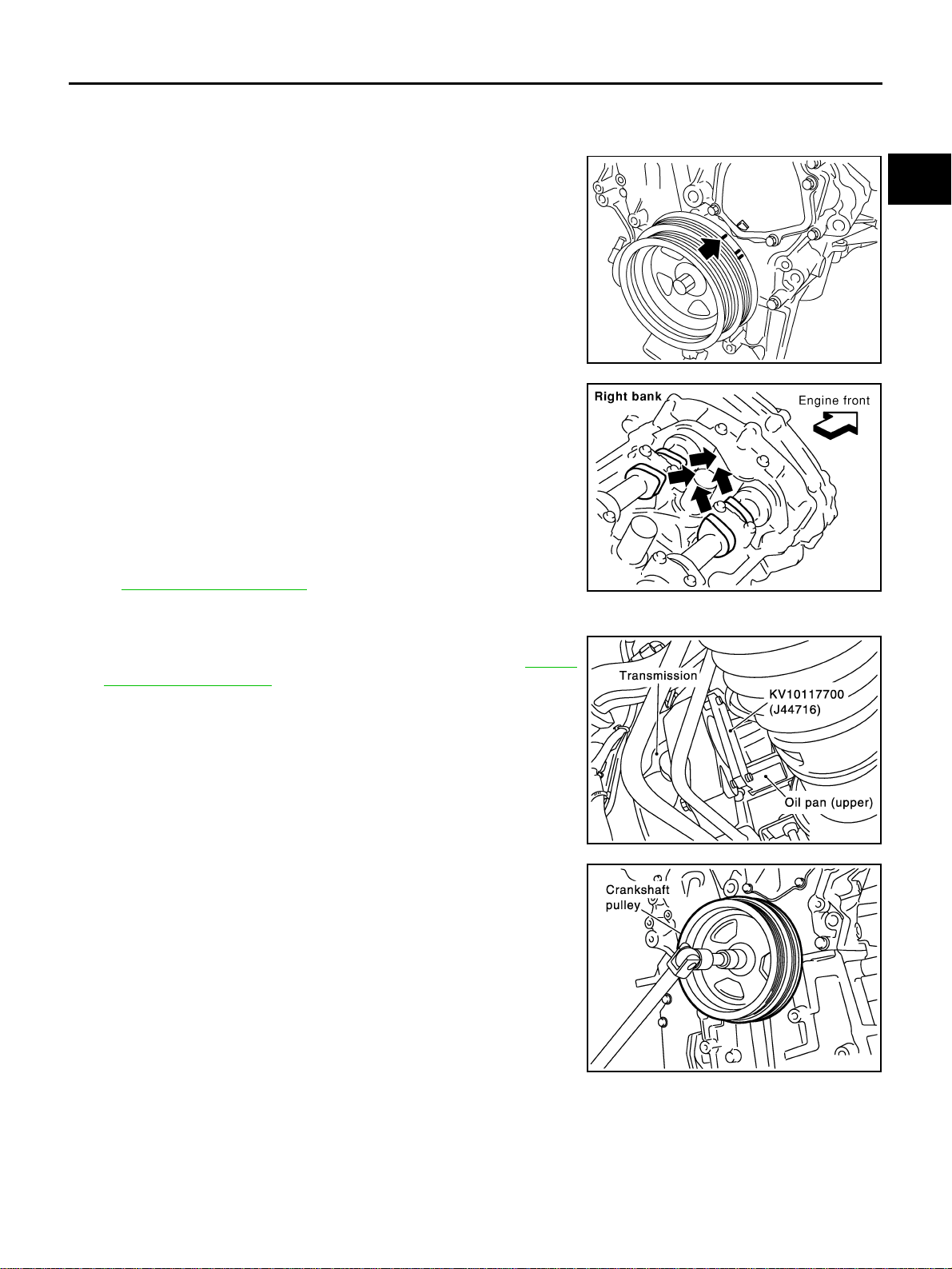
FRONT TIMING CHAIN CASE
EM-55
[VQ35DE]
C
D
E
F
G
H
I
J
K
L
M
A
EM
Revision: 2004 November 2004 FX35/FX45
17. Obtain compression TDC of No. 1 cylinder as follows:
NOTE:
When timing chain is not removed/installed, this step is not required.
a. Rotate crankshaft pulley clockwise to align timing mark (grooved
line without color) with timing indicator.
b. Make sure intake and exhaust cam noses on No. 1 cylinder
(engine front side of right bank) are located as shown in the fig-
ure.
● If not, turn crankshaft one revolution (360°) and align as
shown.
NOTE:
When only primary timing chain is removed, rocker cover
does not need to be removed. To confirm that No. 1 cylinder is
at its compression TDC, remove front timing chain case first.
Then check mating marks on camshaft sprockets. Refer to
EM-63, "
TIMING CHAIN" .
18. Remove crankshaft pulley with the following procedure:
a. Remove rear cover plate (2WD) or starter motor (AWD) and set
ring gear stopper (SST) as shown in the figure. Refer to SC-10,
"STARTING SYSTEM" .
b. Loosen crankshaft pulley bolt and locate bolt seating surface as
10 mm (0.39 in) from its original position.
CAUTION:
Do not remove crankshaft pulley bolt as it will be used as a
supporting point for suitable puller.
KBIA1717J
SEM418G
PBIC1098E
PBIC1103E
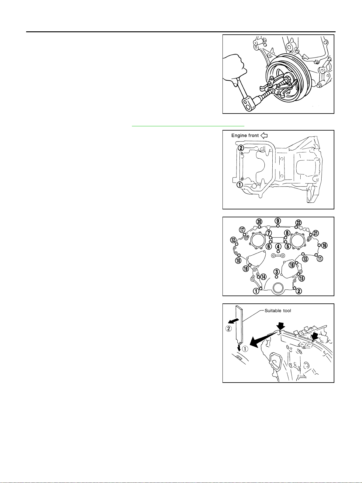
EM-56
[VQ35DE]
FRONT TIMING CHAIN CASE
Revision: 2004 November 2004 FX35/FX45
c. Place suitable puller tab on holes of crankshaft pulley, and pull
crankshaft pulley through.
CAUTION:
Do not put suitable puller tab on crankshaft pulley periph-
ery, as this will damage internal damper.
19. Remove oil pan (lower). Refer to EM-30, "
OIL PAN AND OIL STRAINER" .
20. Loosen two mounting bolts in front of oil pan (upper) with power
tool in reverse order as shown in the figure.
21. Remove front timing chain case.
a. Loosen mounting bolts with power tool in reverse order as
shown in the figure.
b. Insert suitable tool into the notch at the top of front timing chain
case as shown (1) in the figure.
c. Pry off case by moving tool as shown (2) in the figure.
● Use seal cutter [SST: KV10111100 (J-37228)] or an equivalent
tool to cut liquid gasket for removal.
CAUTION:
● Do not use screwdrivers or something similar.
● After removal, handle it carefully so it does not tilt,
cant, or warp under a load.
EMQ0477D
PBIC1116E
KBIA1303E
SEM156F
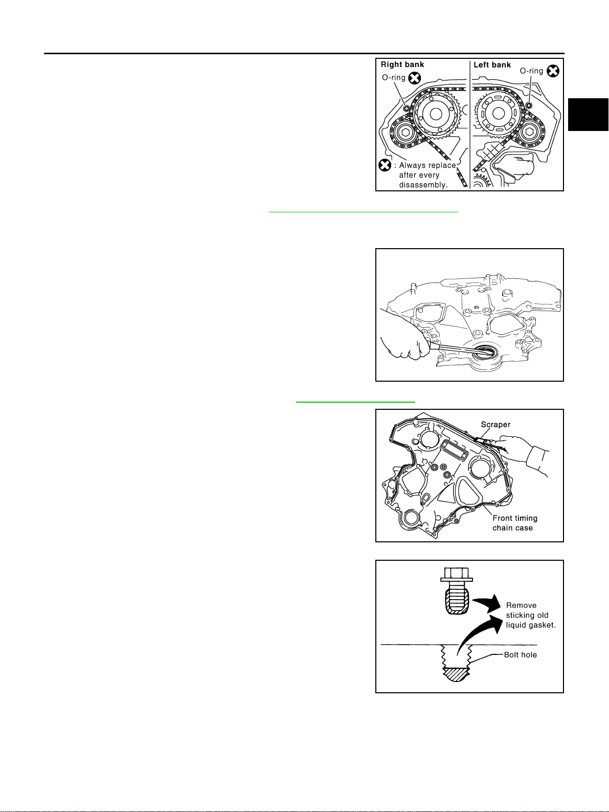
FRONT TIMING CHAIN CASE
EM-57
[VQ35DE]
C
D
E
F
G
H
I
J
K
L
M
A
EM
Revision: 2004 November 2004 FX35/FX45
22. Remove O-rings from rear timing chain case.
23. Remove oil pan gasket front side. Refer to EM-30, "
OIL PAN AND OIL STRAINER" .
24. Remove water pump cover and chain tensioner cover from front timing chain case.
● Use seal cutter [SST: KV10111100 (J-37228)] or an equivalent tool to cut liquid gasket for removal.
25. Remove front oil seal from front timing chain case using a suit-
able tool.
● Use flat-bladed screwdriver for removal.
CAUTION:
Exercise care not to damage front timing chain case.
26. Remove timing chain and related parts. Refer to EM-63, "
TIMING CHAIN" .
27. Use a scraper to remove all traces of old liquid gasket from front
and rear timing chain cases and oil pan (upper), and liquid gas-
ket mating surfaces.
CAUTION:
Be careful not to allow gasket fragments to enter oil pan.
● Remove old liquid gasket from bolt hole and thread.
SBIA0497E
EMQ0032D
SEM737G
PBIC2084E
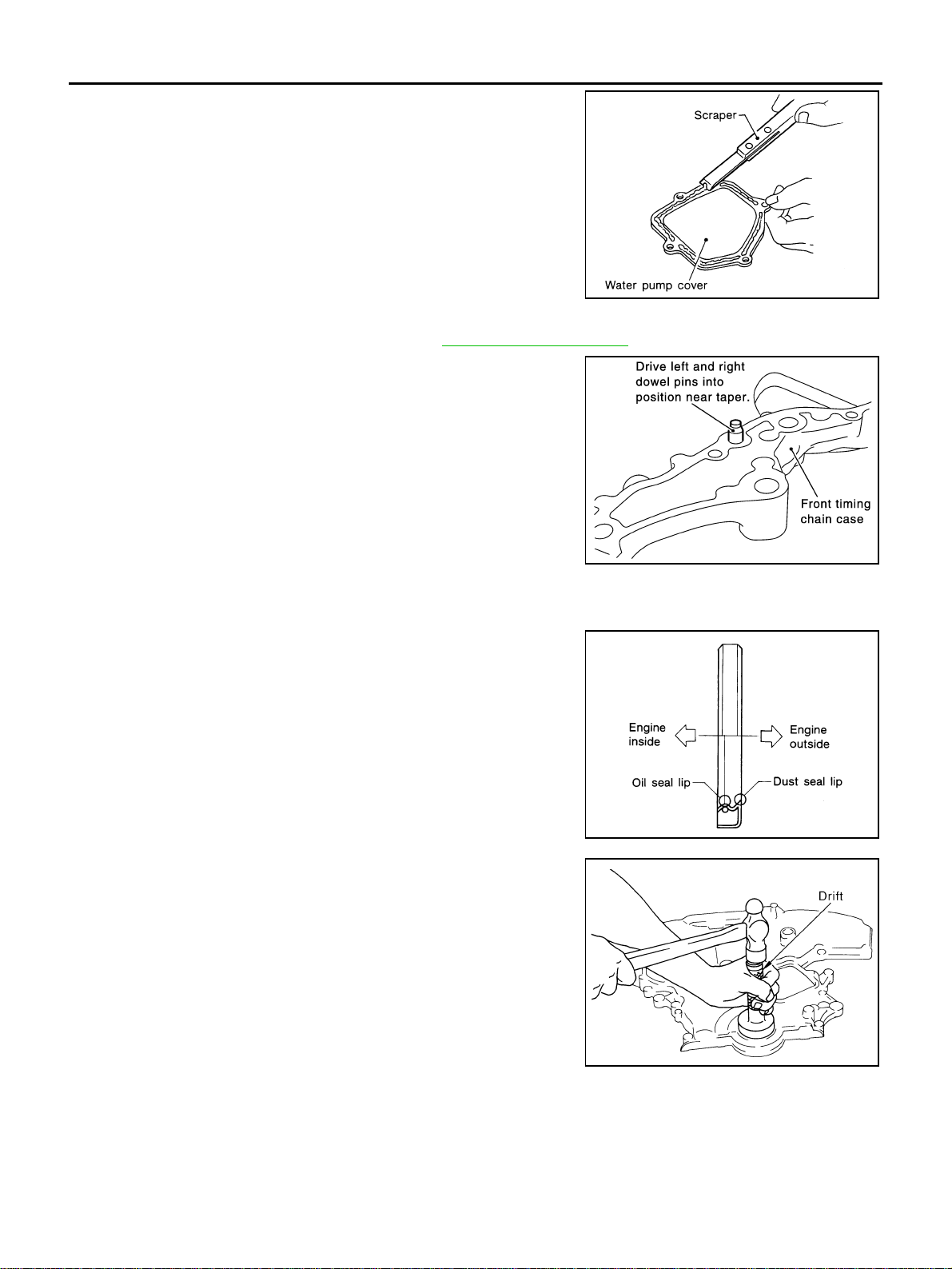
EM-58
[VQ35DE]
FRONT TIMING CHAIN CASE
Revision: 2004 November 2004 FX35/FX45
28. Use a scraper to remove all traces of liquid gasket from water
pump cover, chain tensioner cover and intake valve timing con-
trol covers.
INSTALLATION
1. Install timing chain and related parts. Refer to EM-63, "TIMING CHAIN" .
2. Hammer dowel pins (left and left) into front timing chain case up
to a point close to taper in order to shorten protrusion length.
3. Install front oil seal on front timing chain case.
● Apply new engine oil to the oil seal edges.
● Install it so that each seal lip is oriented as shown in the fig-
ure.
● Using suitable drift, press-fit oil seal until it becomes flush with
front timing chain case end face.
● Make sure the garter spring is in position and seal lip is not
inverted.
SEM926E
PBIC1101E
SEM715A
PBIC0790E
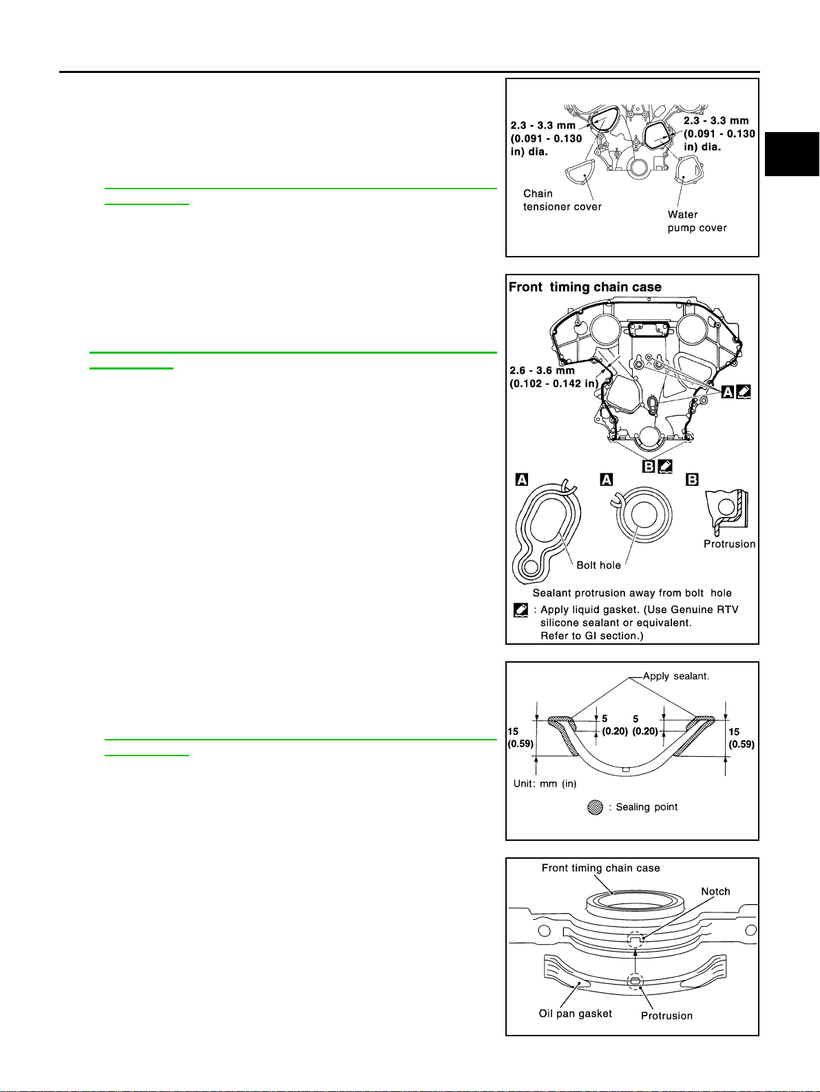
FRONT TIMING CHAIN CASE
EM-59
[VQ35DE]
C
D
E
F
G
H
I
J
K
L
M
A
EM
Revision: 2004 November 2004 FX35/FX45
4. Install water pump cover and chain tensioner cover to front tim-
ing chain case.
● Apply liquid gasket to front timing chain case front side as
shown in the figure with tube presser [SST: WS39930000 ( –
)].
Use Genuine RTV Silicone Sealant or equivalent. Refer to
GI-48, "
RECOMMENDED CHEMICAL PRODUCTS AND
SEALANTS".
5. Install front timing chain case as follows:
a. Apply liquid gasket to front timing chain case back side as
shown in the figure with tube presser [SST: WS39930000 ( – )].
Use Genuine RTV Silicone Sealant or equivalent. Refer to
GI-48, "
RECOMMENDED CHEMICAL PRODUCTS AND
SEALANTS".
b. Install oil pan gasket front side.
● Apply liquid gasket to oil pan gasket as shown in the figure
with tube presser [SST: WS39930000 ( – )].
Use Genuine RTV Silicone Sealant or equivalent. Refer to
GI-48, "
RECOMMENDED CHEMICAL PRODUCTS AND
SEALANTS".
● Align notch of front timing chain case with protrusion of oil pan
gasket.
SEM744GA
PBIC1133E
SEM964E
PBIC1114E
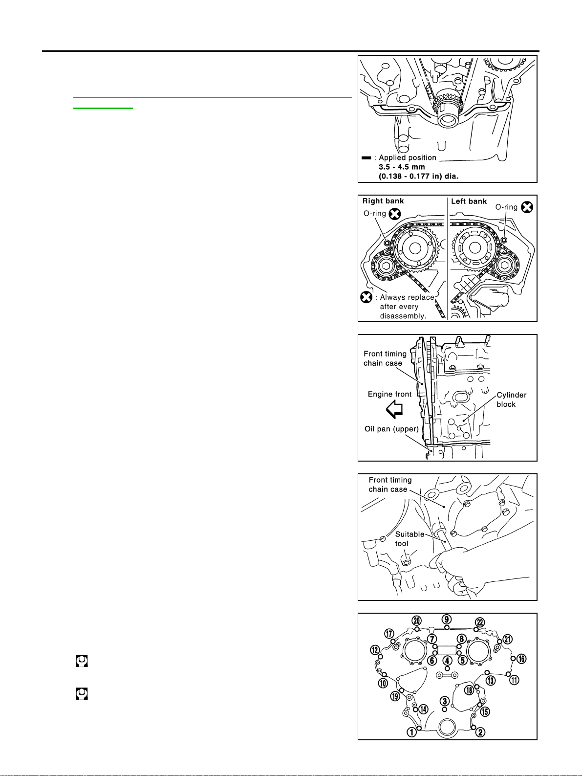
EM-60
[VQ35DE]
FRONT TIMING CHAIN CASE
Revision: 2004 November 2004 FX35/FX45
● Apply liquid gasket to top surface of oil pan (upper) as shown
in the figure with tube presser [SST: WS39930000 ( – )].
Use Genuine RTV Silicone Sealant or equivalent. Refer to
GI-48, "
RECOMMENDED CHEMICAL PRODUCTS AND
SEALANTS".
c. Install new O-rings on rear timing chain case.
d. Assemble front timing chain case as follows.
i. Fit lower end of front timing chain case tightly onto top face of oil
pan (upper). From the fitting point, make entire front timing chain
case contact rear timing chain case completely.
CAUTION:
Be careful that oil pan gasket is in place.
ii. While pressing front timing chain case from its front and top as
shown in the figure, install bolts and temporarily tighten them.
For bolt length and positions, refer to the step 6.
iii. Hammer dowel pin until the outer end becomes flush with sur-
face.
6. Tighten bolts to the specified torque in order as shown in the fig-
ure.
● After tightening, retighten them to specified torque in numeri-
cal order as shown in the figure.
PBIC1099E
SBIA0497E
PBIC1100E
PBIC1115E
8 mm (0.31 in) dia. bolts : 1, 2
: 28.4 N·m (2.9 kg-m, 21 ft-lb)
6 mm (0.24 in) dia. bolts : Except the above
: 12.7 N·m (1.3 kg-m, 9 ft-lb)
KBIA1303E
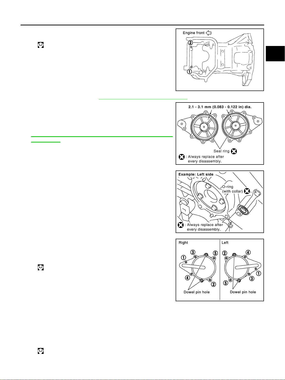
FRONT TIMING CHAIN CASE
EM-61
[VQ35DE]
C
D
E
F
G
H
I
J
K
L
M
A
EM
Revision: 2004 November 2004 FX35/FX45
7. Install two mounting bolts in front of oil pan (upper) in numerical
order as shown in the figure.
8. Install oil pan (lower). Refer to EM-30, "
OIL PAN AND OIL STRAINER" .
9. Install right and left intake valve timing control covers as follows:
a. Install seal rings in shaft grooves.
b. Apply liquid gasket to intake valve timing control covers with
tube presser [SST: WS39930000 ( – )].
Use Genuine RTV Silicone Sealant or equivalent. Refer to
GI-48, "
RECOMMENDED CHEMICAL PRODUCTS AND
SEALANTS".
c. Install collared O-ring in front timing chain case oil hole (left and
right sides).
d. Being careful not to move seal ring from the installation groove,
align dowel pins on chain case with the holes to install intake
valve timing control covers.
e. Tighten bolts in the numerical order as shown in the figure.
10. Install crankshaft pulley as follows:
a. Fix crankshaft using ring gear stopper [SST: KV10117700 (J-44716)].
b. Install crankshaft pulley, taking care not to damage front oil seal.
● When press-fitting crankshaft pulley with a plastic hammer, tap on its center portion (not circumfer-
ence).
c. Tighten bolt.
: 17.2 N·m (1.8 kg-m, 13 ft-lb)
PBIC1116E
SBIA0492E
PBIC2045E
: 11.3 N·m (1.2 kg-m, 8 ft-lb)
PBIC0918E
: 44.1 N·m (4.5 kg-m, 33 ft-lb)
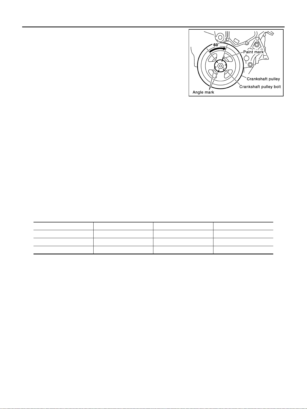
EM-62
[VQ35DE]
FRONT TIMING CHAIN CASE
Revision: 2004 November 2004 FX35/FX45
d. Put a paint mark on crankshaft pulley aligning with angle mark
on crankshaft pulley bolt. Then, further retighten bolt by “60”
degrees (equivalent to one graduation)].
11. Rotate crankshaft pulley in normal direction (clockwise when viewed from front) to confirm it turns
smoothly.
12. For the following operations, perform steps in the reverse order of removal.
NOTE:
If hydraulic pressure inside chain tensioner drops after removal/installation, slack in the guide may gener-
ate a pounding noise during and just after engine start. However, this is normal. Noise will stop after
hydraulic pressure rises.
INSPECTION AFTER INSTALLATION
● Before starting engine, check the levels of engine coolant, lubrications and working fluid. If less than
required quantity, fill to the specified level.
● Run engine to check for unusual noise and vibration.
● Warm up engine thoroughly to make sure there is no leakage of engine coolant, engine oil and working
fluid, fuel and exhaust gas.
● Bleed air from passages in pipes and tubes of applicable lines, such as in cooling system.
● After cooling down engine, again check amounts of engine coolant, engine oil and working fluid. Refill to
specified level, if necessary.
Summary of the inspection items:
SEM751G
Item Before starting engine Engine running After engine stopped
Engine coolant Level Leakage Level
Engine oil Level Leakage Level
Working fluid Level Leakage Level
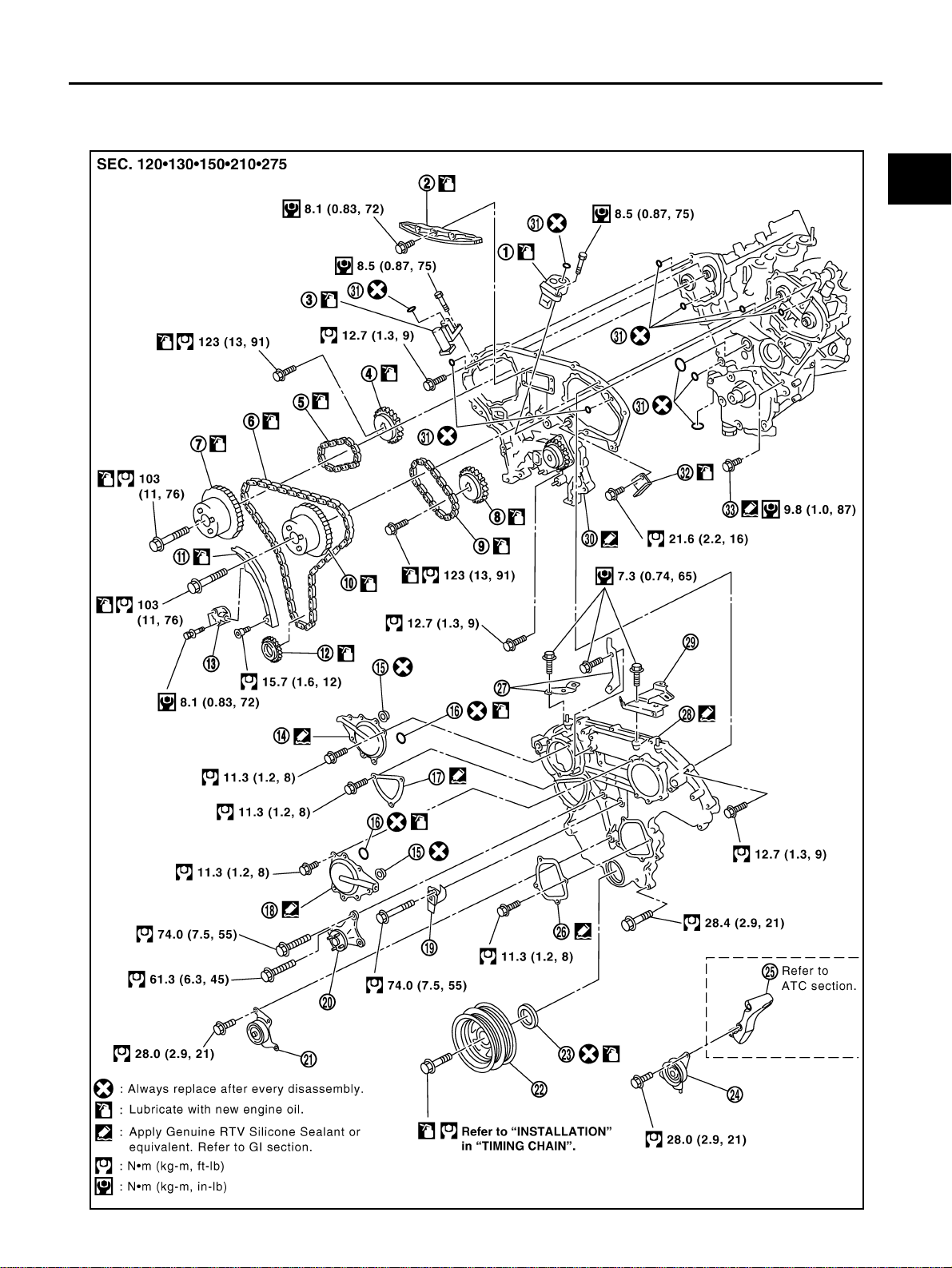
TIMING CHAIN
EM-63
[VQ35DE]
C
D
E
F
G
H
I
J
K
L
M
A
EM
Revision: 2004 November 2004 FX35/FX45
TIMING CHAIN PFP:13028
Removal and Installation ABS004XE
SBIA0588E
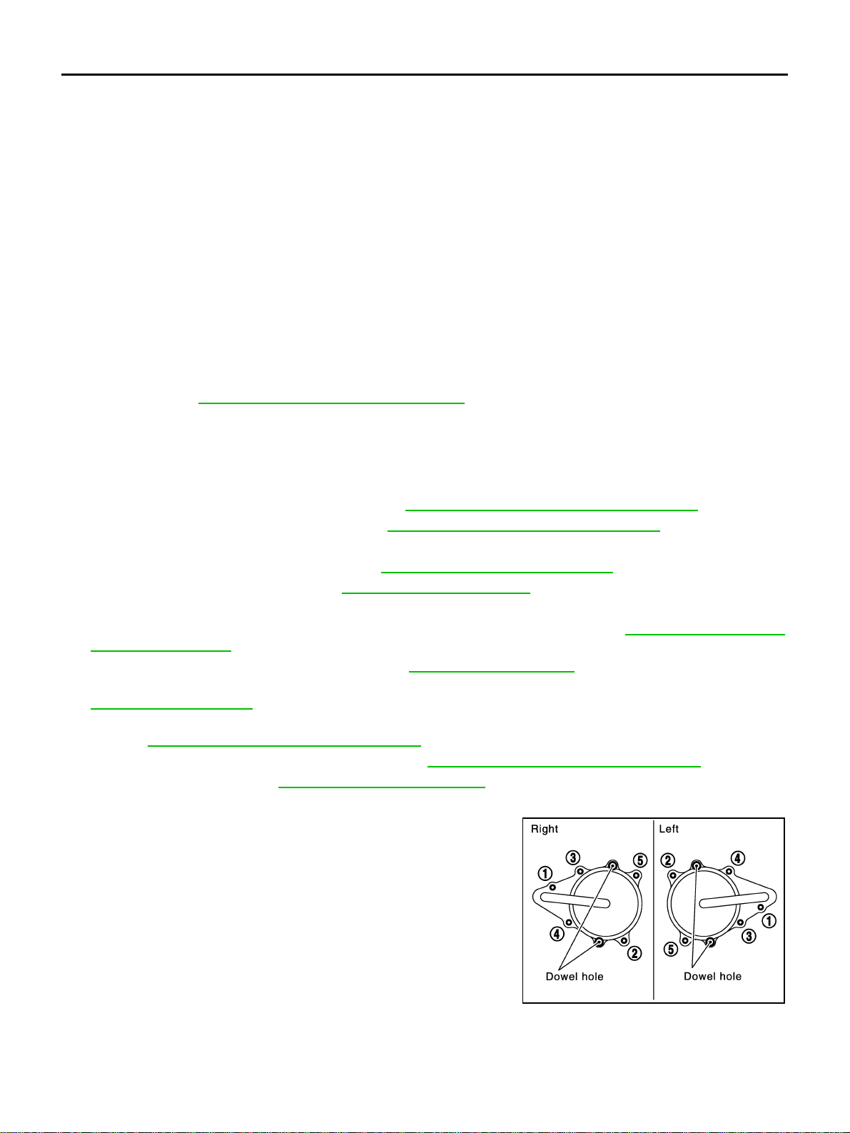
EM-64
[VQ35DE]
TIMING CHAIN
Revision: 2004 November 2004 FX35/FX45
NOTE:
● This section describes procedures for removing/installing front timing chain case and timing chain related
parts, and rear timing chain case, when oil pan (upper) needs to be removed/installed for engine overhaul,
etc.
● To remove/install front timing chain case, timing chain, and its related parts without removing oil pan
(upper), refer to EM-54, "
FRONT TIMING CHAIN CASE" .
REMOVAL
1. Place vehicle onto lift.
2. Remove front tire.
3. Disconnect negative battery terminal.
4. Remove engine cover with power tool. Refer to EM-19, "
INTAKE MANIFOLD COLLECTOR" .
5. Remove air cleaner case assembly. Refer to EM-17, "
AIR CLEANER AND AIR DUCT" .
6. Remove front and rear engine undercover with power tool.
7. Drain engine coolant from radiator. Refer to CO-11, "
Changing Engine Coolant" .
8. Drain engine oil from oil pan. Refer to LU-9, "
Changing Engine Oil" .
9. Remove engine harnesses.
10. Remove intake manifold collectors (upper and lower) with power tool. Refer to EM-19, "
INTAKE MANI-
FOLD COLLECTOR" .
11. Remove radiator cooling fan assembly. Refer to CO-21, "
COOLING FAN" .
12. Remove A/C compressor from bracket with piping connected, and temporarily secure it aside. Refer to
ATC-139, "
Components" .
13. Remove power steering oil pump from bracket with piping connected, and temporarily secure it aside.
Refer to PS-31, "
POWER STEERING OIL PUMP" .
14. Remove power steering oil pump bracket. Refer to PS-31, "
POWER STEERING OIL PUMP" .
15. Remove alternator. Refer to SC-23, "
CHARGING SYSTEM" .
16. Remove water bypass hose, water hose clamp and idler pulley bracket from front timing chain case.
17. Remove right and left intake valve timing control covers with
power tool.
● Loosen bolts in reverse order as shown in the figure.
● Use seal cutter [SST: KV10111100 (J-37228)] or an equivalent
tool to cut liquid gasket for removal.
CAUTION:
Shaft is internally jointed with intake camshaft sprocket
center hole. When removing, keep it horizontal until it is
completely disconnected.
1. Timing chain tensioner (secondary) 2. Internal chain guide 3. Timing chain tensioner (secondary)
4. Camshaft sprocket (EXH) 5. Timing chain (secondary) 6. Timing chain (primary)
7. Camshaft sprocket (INT) 8. Camshaft sprocket (EXH) 9. Timing chain (secondary)
10. Camshaft sprocket (INT) 11. Slack guide 12. Crankshaft sprocket
13. Timing chain tensioner (primary) 14. Intake valve timing control cover 15. Collared O-ring
16. O-ring 17. Chain tensioner cover 18. Intake valve timing control cover
19. Water hose clamp 20. Idler pulley bracket 21. Idler pulley
22. Crankshaft pulley 23. Front oil seal 24. Idler pulley
25. A/C compressor bracket 26. Water pump cover 27. Bracket
28. Front timing chain case 29. Bracket 30. Rear timing chain case
31. O-ring 32. Tension guide 33. Water drain plug (front side)
SEM728G
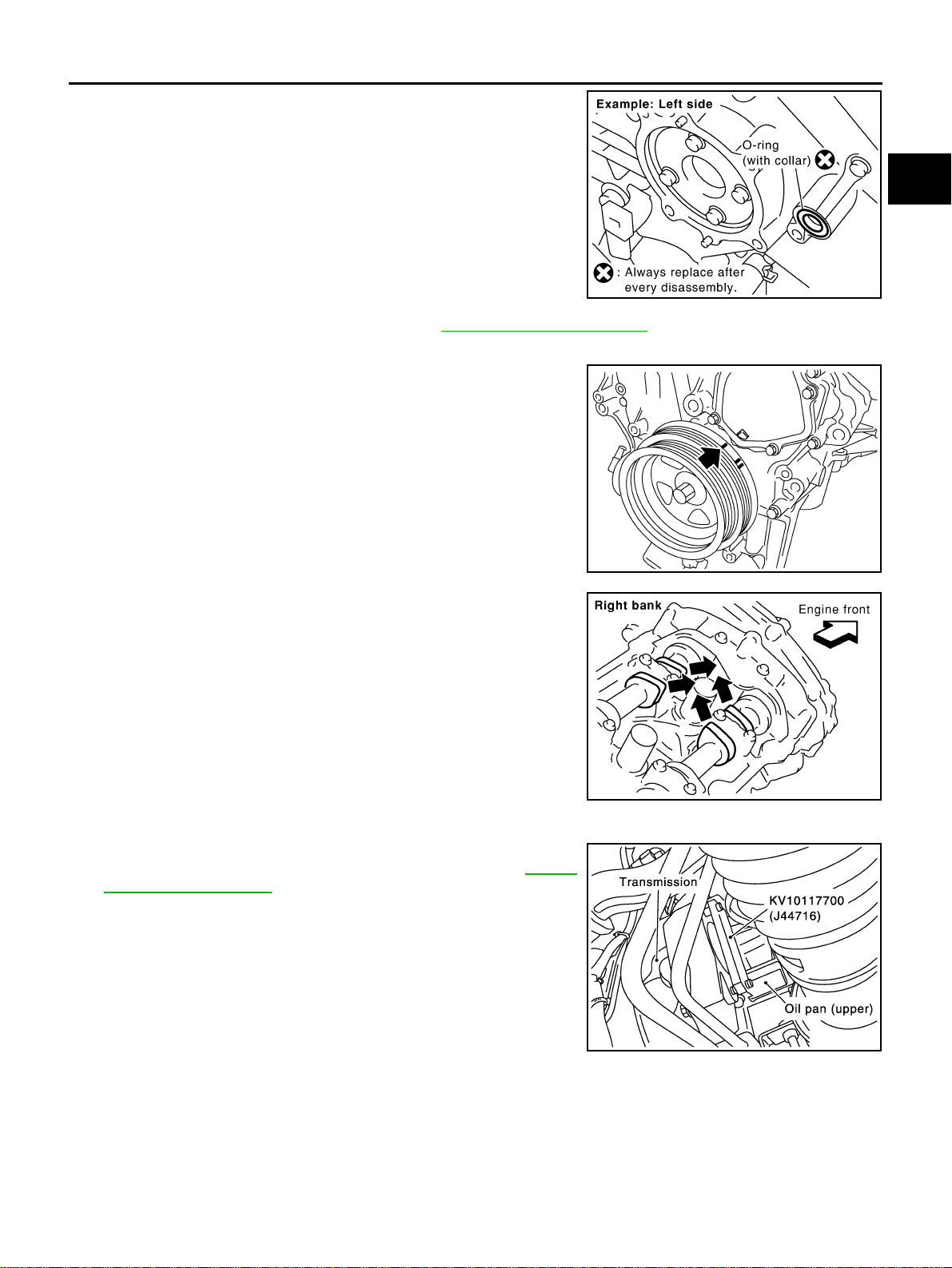
TIMING CHAIN
EM-65
[VQ35DE]
C
D
E
F
G
H
I
J
K
L
M
A
EM
Revision: 2004 November 2004 FX35/FX45
18. Remove collared O-ring from front timing chain case (left and
right side).
19. Remove right and left rocker covers. Refer to EM-51, "
ROCKER COVER" .
20. Obtain compression TDC of No. 1 cylinder as follows:
a. Rotate crankshaft pulley clockwise to align timing mark (grooved
line without color) with timing indicator.
b. Make sure intake and exhaust cam noses on No. 1 cylinder
(engine front side of right bank) are located as shown in the fig-
ure.
● If not, turn crankshaft one revolution (360°) and align as
shown.
21. Remove crankshaft pulley with the following procedure:
a. Remove rear cover plate (2WD) or starter motor (AWD) and set
ring gear stopper (SST) as shown in the figure. Refer to SC-10,
"STARTING SYSTEM" .
PBIC2045E
KBIA1717J
SEM418G
PBIC1098E
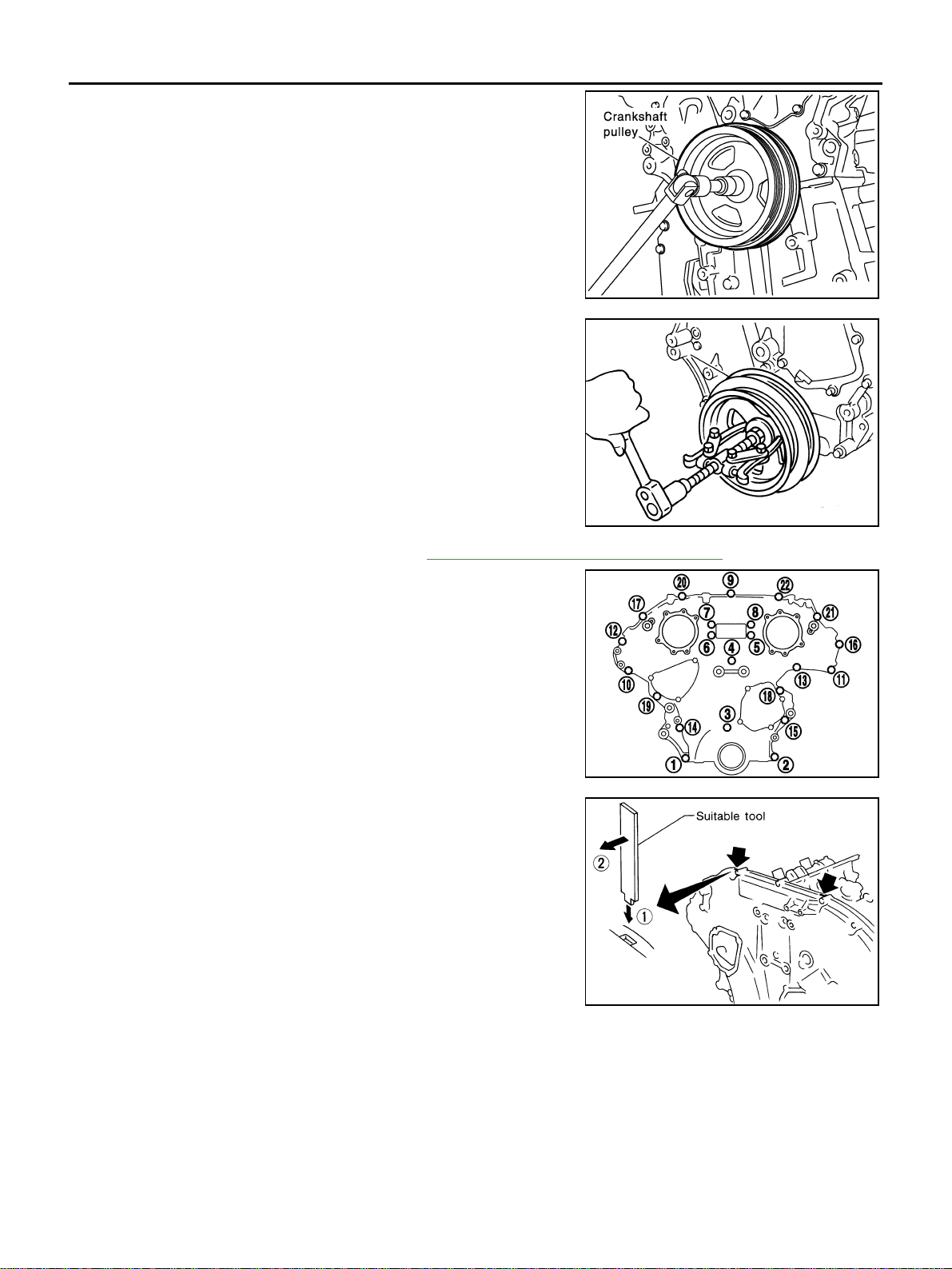
EM-66
[VQ35DE]
TIMING CHAIN
Revision: 2004 November 2004 FX35/FX45
b. Loosen crankshaft pulley bolt and locate bolt seating surface as
10 mm (0.39 in) from its original position.
CAUTION:
Do not remove crankshaft pulley bolt as it will be used as a
supporting point for suitable puller.
c. Place suitable puller tab on holes of crankshaft pulley, and pull
crankshaft pulley through.
CAUTION:
Do not put suitable puller tab on crankshaft pulley periph-
ery, as this will damage internal damper.
22. Remove oil pan (upper and lower). Refer to EM-30, "
OIL PAN AND OIL STRAINER" .
23. Remove front timing chain case.
a. Loosen mounting bolts with power tool in reverse order as
shown in the figure.
b. Insert suitable tool into the notch at the top of front timing chain
case as shown (1) in the figure.
c. Pry off case by moving tool as shown (2) in the figure.
● Use seal cutter [SST: KV10111100 (J-37228)] or an equivalent
tool to cut liquid gasket for removal.
CAUTION:
● Do not use screwdrivers or something similar.
● After removal, handle it carefully so it does not tilt,
cant, or warp under a load.
PBIC1103E
EMQ0477D
KBIA1303E
SEM156F
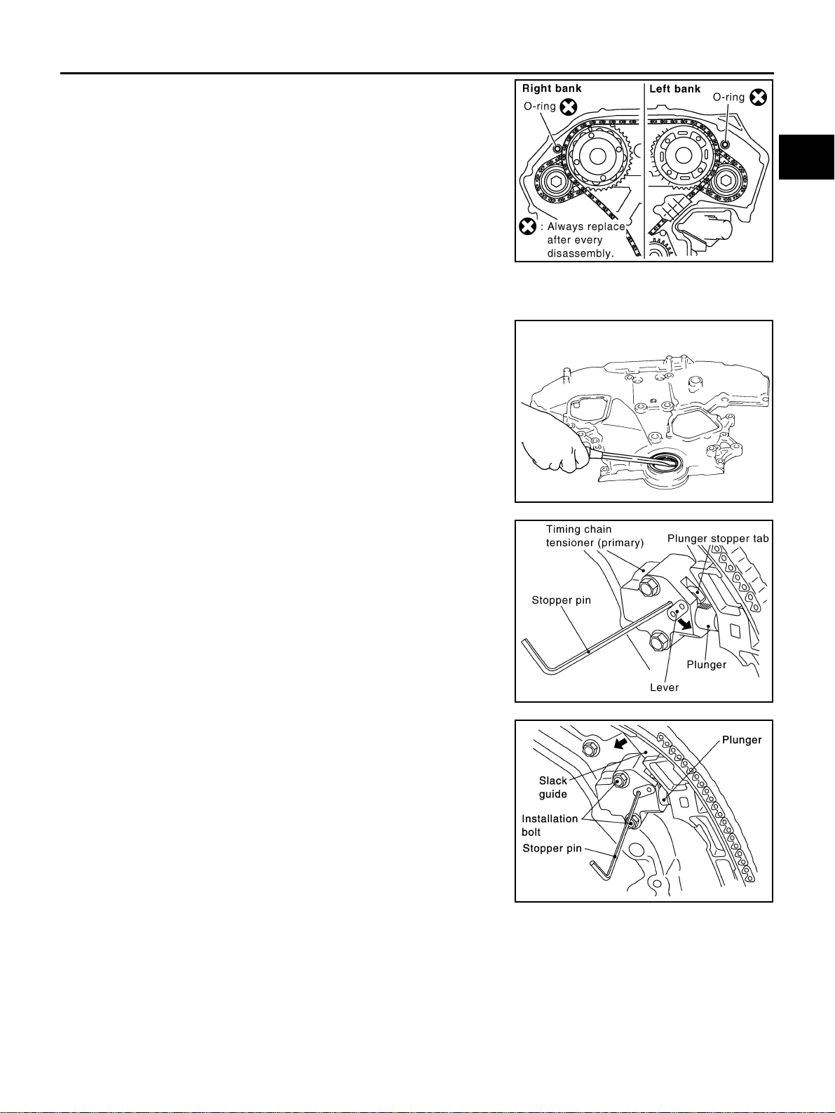
TIMING CHAIN
EM-67
[VQ35DE]
C
D
E
F
G
H
I
J
K
L
M
A
EM
Revision: 2004 November 2004 FX35/FX45
24. Remove O-rings from rear timing chain case.
25. Remove water pump cover and chain tensioner cover from front timing chain case.
● Use seal cutter [SST: KV10111100 (J-37228)] or an equivalent tool to cut liquid gasket for removal.
26. Remove front oil seal from front timing chain case using a suit-
able tool.
● Use screwdriver for removal.
CAUTION:
Be careful not to damage front timing chain case.
27. Remove timing chain tensioner (primary) as the following:
a. Pull lever down and release plunger stopper tab.
● Plunger stopper tab can be pushed up to release (coaxial
structure with lever).
b. Insert stopper pin into tensioner body hole to hold lever, and
keep the tab released.
NOTE:
An Allen wrench [2.5 mm (0.098 in)] is used for a stopper pin as
an example.
c. Insert plunger into tensioner body by pressing slack guide.
d. Keep slack guide pressed and hold it by pushing stopper pin
through the lever hole and body hole.
e. Remove mounting bolts and remove timing chain tensioner (pri-
mary).
SBIA0497E
EMQ0032D
PBIC2107E
SEM733G
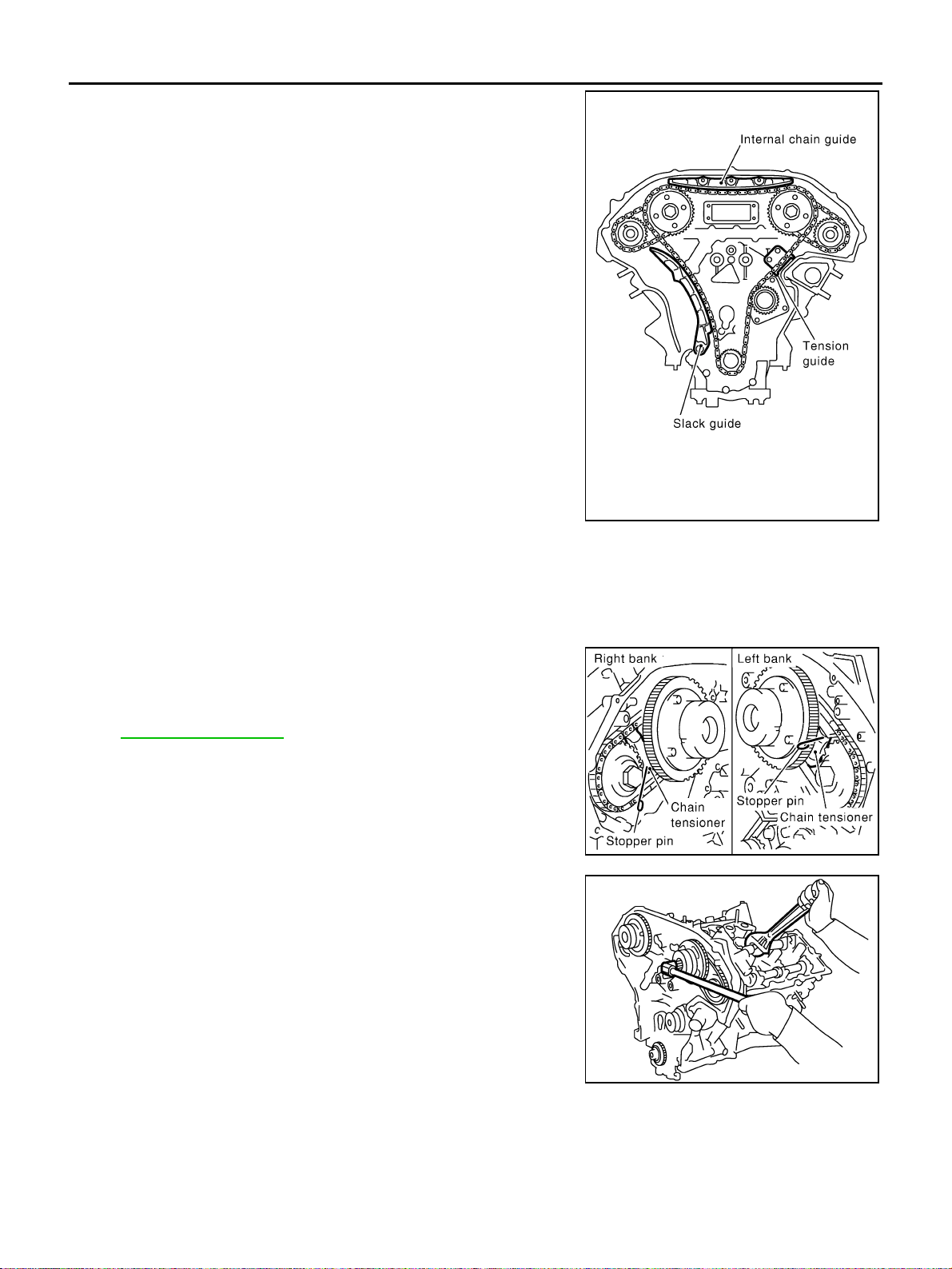
EM-68
[VQ35DE]
TIMING CHAIN
Revision: 2004 November 2004 FX35/FX45
28. Remove internal chain guide, tension guide and slack guide.
NOTE:
Tension guide can be removed after removing timing chain (pri-
mary).
29. Remove timing chain (primary), tension guide and crankshaft sprocket.
CAUTION:
After removing timing chain, do not turn crankshaft and camshaft separately, or valves will strike
piston heads.
30. Remove timing chain (secondary) and camshaft sprockets as the following:
a. Attach a suitable stopper pin to right and left camshaft chain ten-
sioners (for secondary timing chains).
NOTE:
For removal and installation of secondary chain tensioner, refer
to EM-82, "
CAMSHAFT" . (Removing No. 1 camshaft bracket is
required.)
b. Remove intake and exhaust camshaft sprocket bolts.
● Apply paint to timing chain and camshaft sprockets for align-
ment during installation.
● Secure the hexagonal portion of camshaft using a wrench to
loosen mounting bolts.
c. Remove timing chain (secondary) together with camshaft sprockets.
● Turn camshaft slightly to secure slackness of timing chain on timing chain tensioner (secondary) side.
PBIC2266E
SEM923G
KBIA1698J
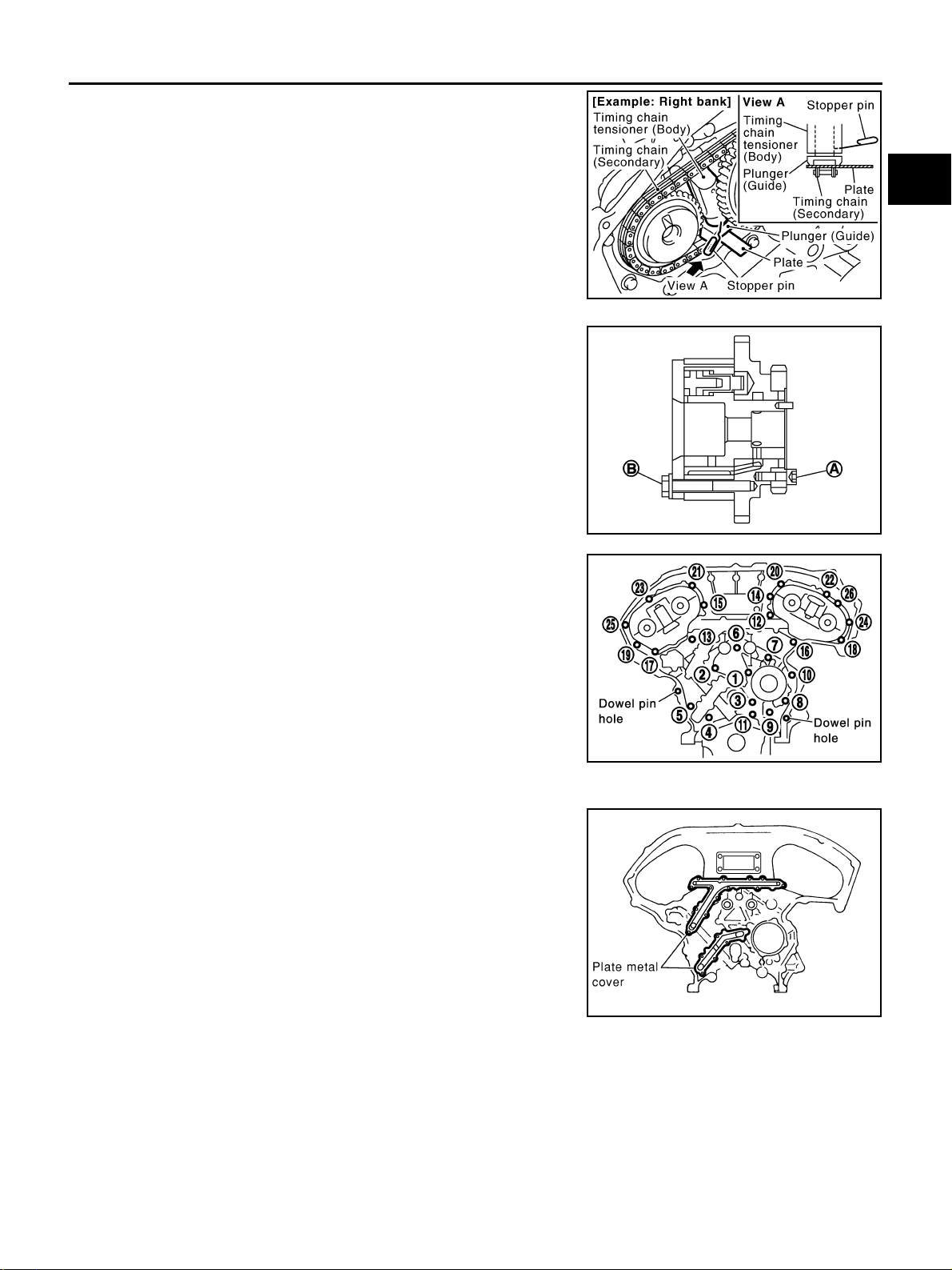
TIMING CHAIN
EM-69
[VQ35DE]
C
D
E
F
G
H
I
J
K
L
M
A
EM
Revision: 2004 November 2004 FX35/FX45
● Insert 0.5 mm (0.020 in)-thick metal or resin plate between
timing chain and timing chain tensioner plunger (guide).
Remove timing chain (secondary) together with camshaft
sprockets with timing chain loose from guide groove.
CAUTION:
Be careful of plunger coming-off when removing timing
chain (secondary). This is because plunger of timing
chain tensioner (secondary) moves during operation,
leading to coming-off of fixed stopper pin.
NOTE:
Camshaft sprocket (INT) is two-for-one structure of primary
and secondary sprockets.
● When handling camshaft sprocket (INT), be careful of the fol-
lowing:
CAUTION:
● Handle carefully to avoid any shock to camshaft
sprocket.
● Do not disassemble. (Do not loosen bolts “A” and “B”
as shown in the figure).
31. Remove rear timing chain case as follows:
a. Loosen and remove mounting bolts in reverse order as shown in
the figure.
b. Cut sealant using a seal cutter [SST: KV10111100 (J-37228)] or
an equivalent tool and remove rear timing chain case.
CAUTION:
● Do not remove plate metal cover of engine oil passage.
● After removing chain case, do not apply any load which
affects flatness.
PBIC1978E
SEM734G
SEM735G
KBIA1307E
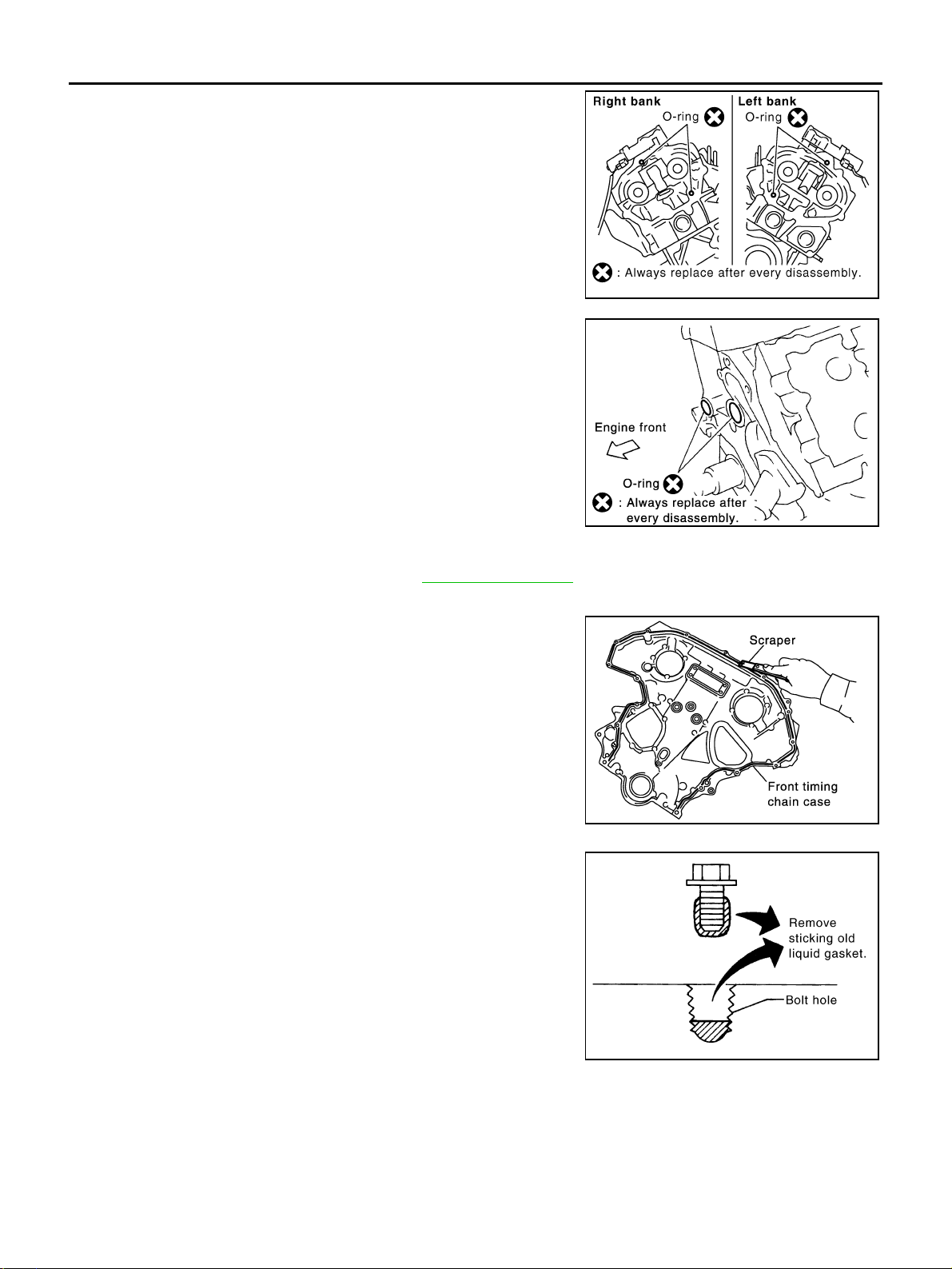
EM-70
[VQ35DE]
TIMING CHAIN
Revision: 2004 November 2004 FX35/FX45
32. Remove O-rings from cylinder head.
33. Remove O-rings from cylinder block.
34. Remove timing chain tensioners (secondary) from cylinder head as the following, if necessary.
a. Remove No. 1 camshaft brackets. Refer to EM-83, "
REMOVAL" .
b. Remove timing chain tensioners (secondary) with stopper pin attached.
35. Use a scraper to remove all traces of liquid gasket from front
and rear timing chain cases, and opposite mating surfaces.
CAUTION:
Be careful not to allow gasket fragments to enter oil pan.
● Remove old liquid gasket from the bolt hole and thread.
SBIA0496E
PBIC0788E
SEM737G
PBIC2084E
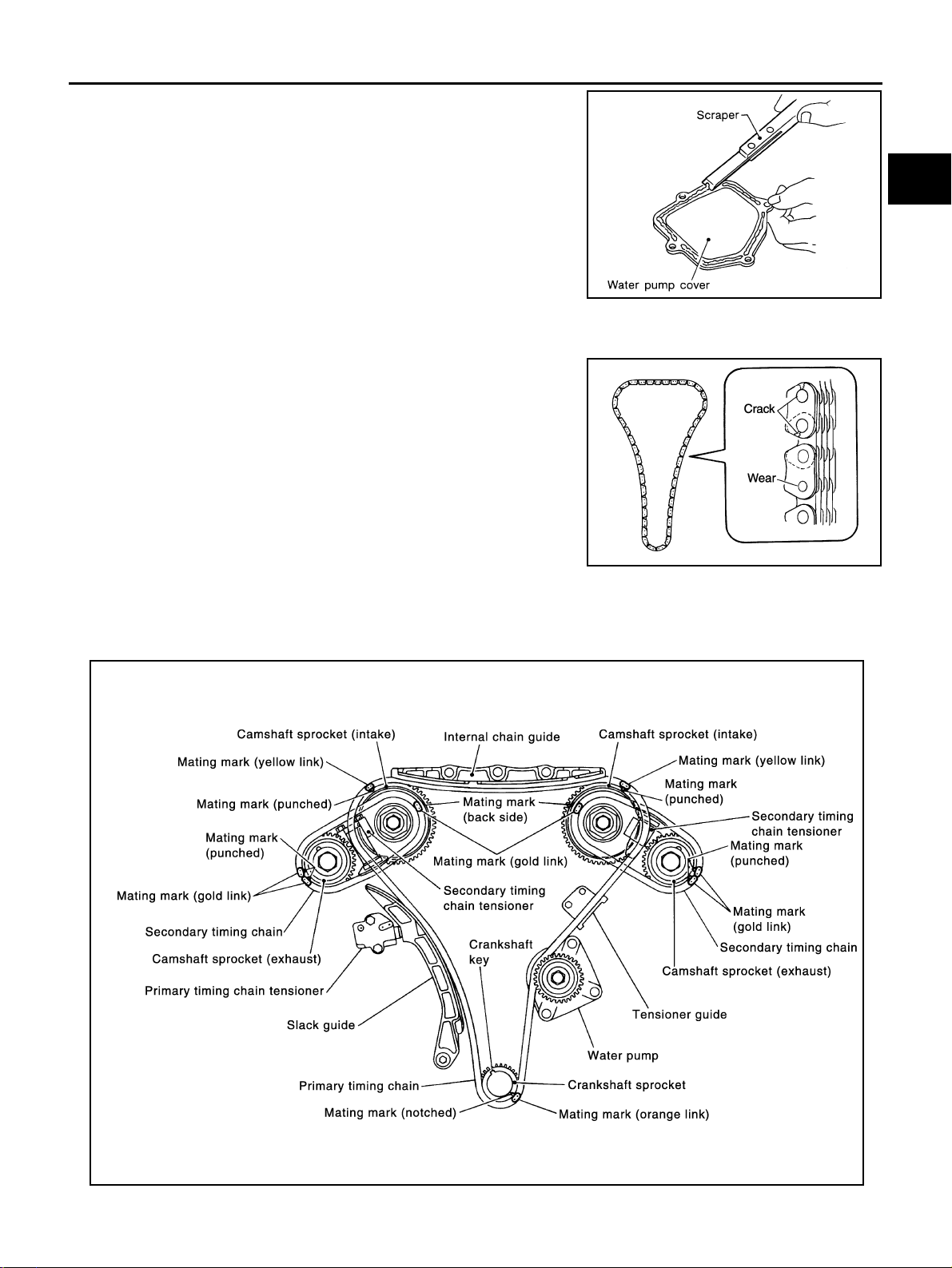
TIMING CHAIN
EM-71
[VQ35DE]
C
D
E
F
G
H
I
J
K
L
M
A
EM
Revision: 2004 November 2004 FX35/FX45
36. Use a scraper to remove all traces of liquid gasket from water
pump cover, chain tensioner cover and intake valve timing con-
trol covers.
INSPECTION AFTER REMOVAL
Timing Chain
Check for cracks and any excessive wear at link plates and roller
links of timing chain. Replace timing chain as necessary.
INSTALLATION
NOTE:
The below figure shows the relationship between the mating mark on each timing chain and that on the corre-
sponding sprocket, with the components installed.
SEM926E
PBIC0282E
KBIA1053E
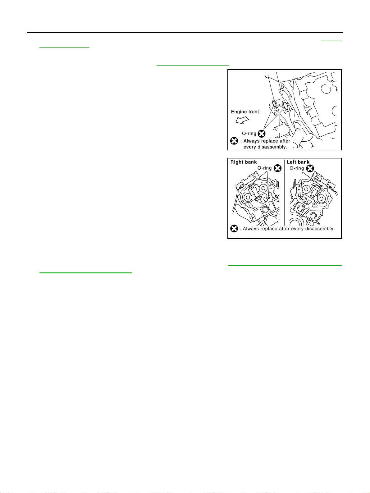
EM-72
[VQ35DE]
TIMING CHAIN
Revision: 2004 November 2004 FX35/FX45
1. Install timing chain tensioners (secondary) to cylinder head as the following if removed. Refer to EM-87,
"INSTALLATION" .
a. Install chain tensioners with stopper pin attached and new O-rings.
b. Install No. 1 camshaft brackets. Refer to EM-87, "
INSTALLATION" .
2. Install new O-rings onto cylinder block.
3. Install new O-rings to cylinder head.
4. Apply liquid gasket to rear timing chain case back side as shown with tube presser [SST: WS39930000 ( –
)].
Use Genuine RTV Silicone Sealant or equivalent. Refer to GI-48, "
RECOMMENDED CHEMICAL
PRODUCTS AND SEALANTS".
CAUTION:
● For “A” in the figure, completely wipe out liquid gasket extended on a portion touching at
engine coolant.
PBIC0788E
SBIA0496E
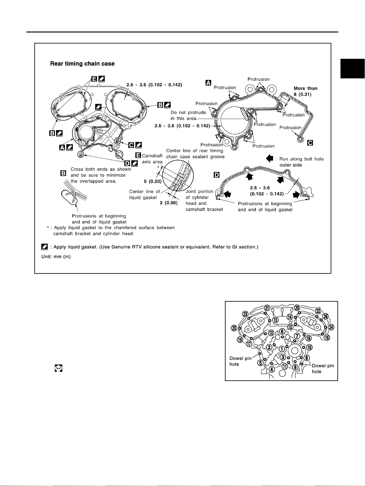
TIMING CHAIN
EM-73
[VQ35DE]
C
D
E
F
G
H
I
J
K
L
M
A
EM
Revision: 2004 November 2004 FX35/FX45
● Apply liquid gasket on installation position of water pump and cylinder head very completely.
5. Align rear timing chain case and water pump assembly with dowel pins (right and left) on cylinder block
and install case.
● Make sure O-rings stay in place during installation to cylinder block and cylinder head.
a. Tighten mounting bolts in the numerical order as shown in the
figure.
● There are two bolt lengths used. Follow the below for proper
bolt length specifications.
b. After all bolts are temporarily tightened, retighten them to the
specification in the numerical order as shown in the figure.
● If RTV Silicone Sealant protrudes, wipe it off immediately.
Bolt length: Bolt position
20 mm (0.79 in) : 1, 2, 3, 6, 7, 8, 9, 10
16 mm (0.63 in) : Except the above
: 12.7 N·m (1.3 kg-m, 9 ft-lb)
PBIC1131E
SEM735G
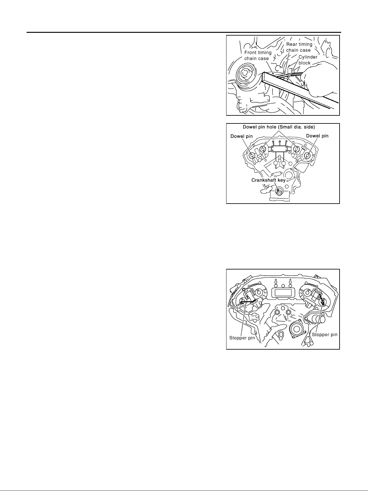
EM-74
[VQ35DE]
TIMING CHAIN
Revision: 2004 November 2004 FX35/FX45
6. After installing rear timing chain case, check surface height dif-
ference between following parts on oil pan mounting surface.
● If not within standard, repeat above installation procedure.
7. Position crankshaft so No. 1 piston is set at TDC on the com-
pression stroke.
● Make sure that dowel pin hole, dowel pin and crankshaft key
are located as shown in the figure.
NOTE:
Though camshaft does not stop at position as shown in the
figure, for the placement of cam nose, it is generally accepted
camshaft is placed for the same direction of the figure.
CAUTION:
Hole on small dia. side must be used for intake side dowel pin hole. Do not misidentify (ignore
big dia. side).
8. Install timing chains (secondary) and camshaft sprockets.
CAUTION:
Matching marks between timing chain and sprockets slip
easily. Confirm all matching mark positions repeatedly dur-
ing the installation process.
a. Push plunger of secondary chain tensioner and keep it pressed
in with a stopper pin.
Standard (Rear timing chain case to cylinder block):
–0.24 to 0.14 mm (–0.0094 to 0.0055 in)
SEM943G
Camshaft dowel pin hole (intake side)
: At cylinder head upper face side in each bank.
Camshaft dowel pin (exhaust side)
: At cylinder head upper face side in each bank.
Crankshaft key
: At cylinder head side of right bank.
KBIA1073E
SEM430G
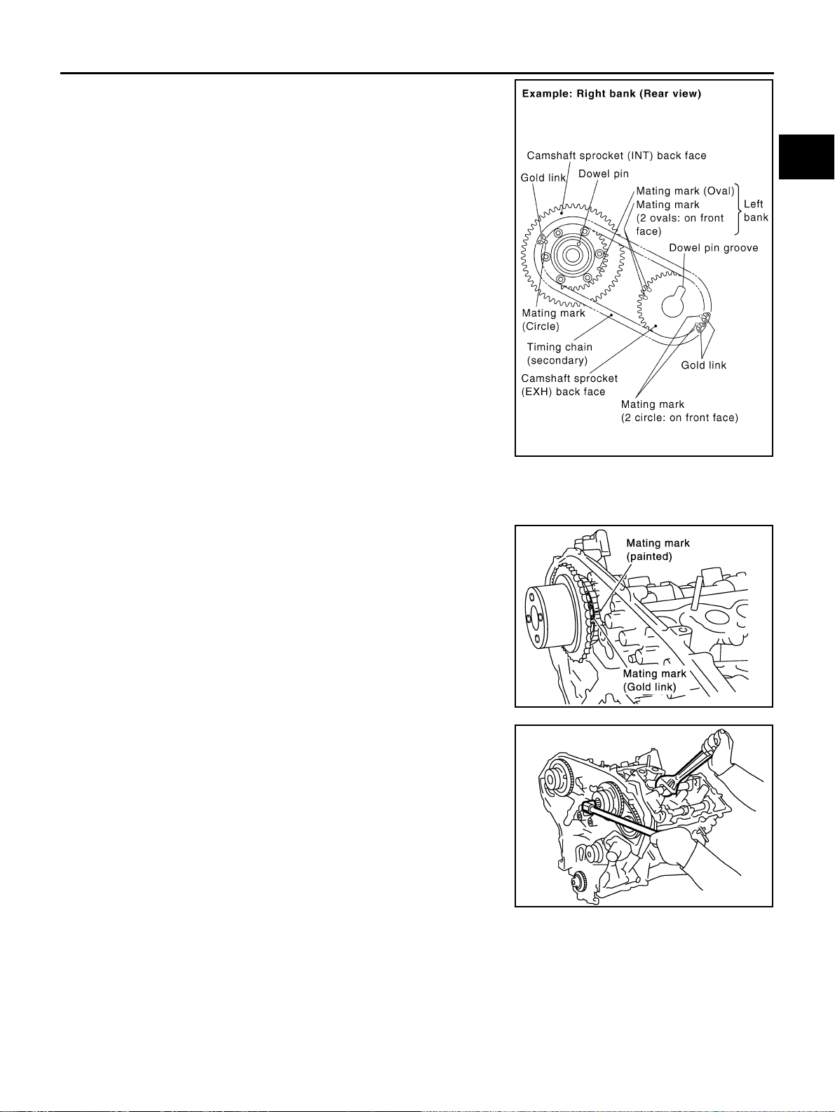
TIMING CHAIN
EM-75
[VQ35DE]
C
D
E
F
G
H
I
J
K
L
M
A
EM
Revision: 2004 November 2004 FX35/FX45
b. Install timing chains (secondary) and camshaft sprockets.
● Align the mating marks on secondary timing chain (gold link)
with the ones on intake and exhaust camshaft sprockets
(stamped), and install them.
NOTE:
● Mating marks for intake camshaft sprocket are on the back
side of secondary camshaft sprocket.
● There are two types of mating marks, circle and oval types.
They should be used for the right and left banks, respec-
tively.
● Align dowel pin and pin hole on camshaft with the groove and
dowel pin on sprocket, and install them.
● On the intake side, align the pin hole on the small diameter
side of camshaft front end with dowel pin on the back side of
camshaft sprocket, and install them.
● On the exhaust side, align dowel pin on camshaft front end
with the pin groove on camshaft sprocket, and install them.
● In case that positions of each mating mark and each dowel
pin are not fit on mating parts, make fine adjustment to the
position holding the hexagonal portion on camshaft with wrench or equivalent.
● Mounting bolts for camshaft sprockets must be tightened in the next step. Tightening them by hand is
enough to prevent the dislocation of dowel pins.
● It may be difficult to visually check the dislocation of mating
marks during and after installation. To make the matching
easier, make a mating mark on the top of sprocket teeth and
its extended line in advance with paint.
9. After confirming the mating marks are aligned, tighten camshaft
sprocket mounting bolts.
● Secure camshaft using a wrench at the hexagonal portion to
tighten mounting bolts.
Right bank : use circle type.
Left bank : use oval type.
PBIC2049E
PBIC0891E
KBIA1698J
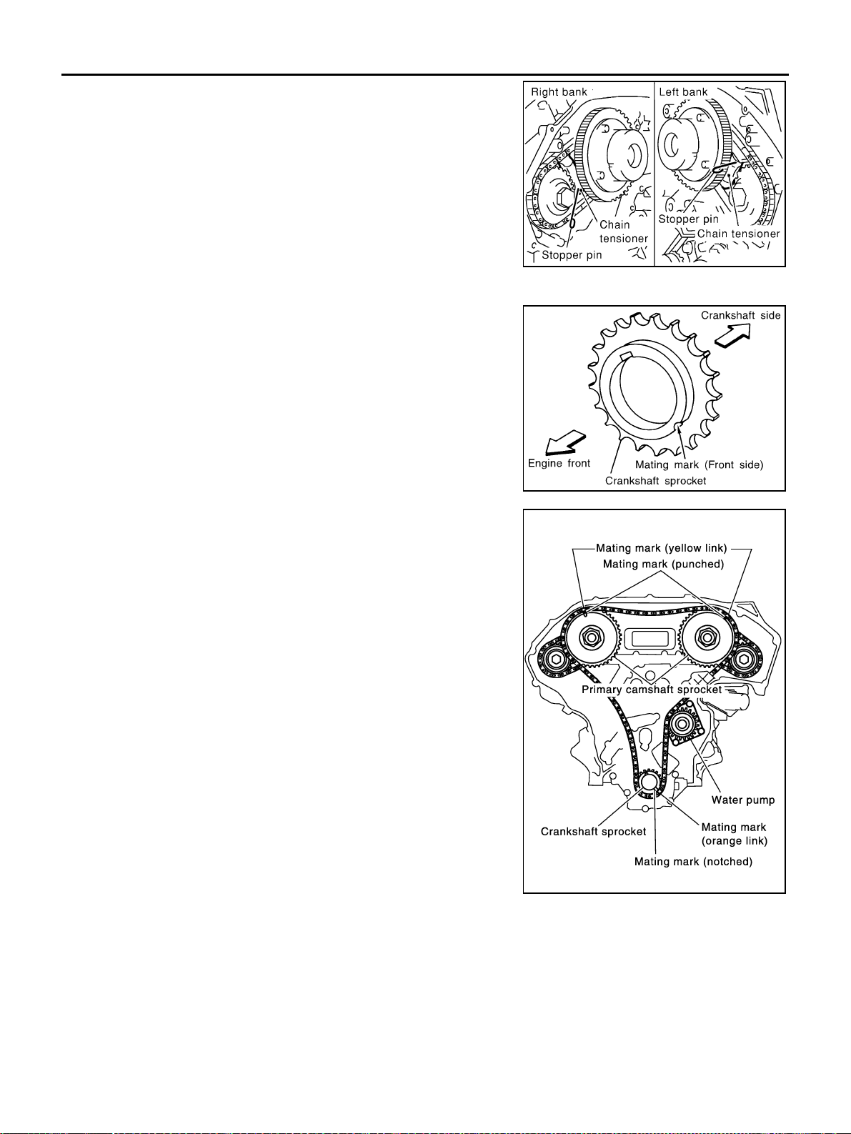
EM-76
[VQ35DE]
TIMING CHAIN
Revision: 2004 November 2004 FX35/FX45
10. Pull stopper pins out from timing chain tensioners (secondary).
11. Install primary timing chain as follows:
a. Install crankshaft sprocket.
● Make sure the mating marks on crankshaft sprocket face the
front of engine.
b. Install primary timing chain.
● Install primary timing chain so the mating mark (punched) on
camshaft sprocket is aligned with the yellow link on timing
chain, while the mating mark (notched) on crankshaft
sprocket is aligned with the orange one on timing chain, as
shown.
● When it is difficult to align mating marks of primary timing
chain with each sprocket, gradually turn camshaft using a
wrench on the hexagonal portion to align it with the mating
marks.
● During alignment, be careful to prevent dislocation of mating
mark alignments of secondary timing chains.
SEM923G
SEM929E
PBIC1132E
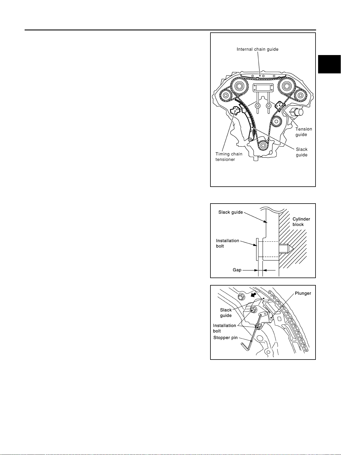
TIMING CHAIN
EM-77
[VQ35DE]
C
D
E
F
G
H
I
J
K
L
M
A
EM
Revision: 2004 November 2004 FX35/FX45
12. Install internal chain guide and timing chain tensioner (primary).
13. Install slack guide.
CAUTION:
Do not overtighten slack guide mounting bolts. It is normal
for a gap to exist under the bolt seats when mounting bolts
are tightened to specification.
14. Install chain tensioner for slack guide.
● When installing chain tensioner, push in sleeve and keep it
pressed in with stopper pin.
● Remove any dirt and foreign materials completely from the
back and the mounting surfaces of chain tensioner.
● After installation, pull out stopper pin by pressing slack guide.
15. Reconfirm that the mating marks on sprockets and timing chain have not slipped out of alignment.
SEM740G
SEM741G
SEM733G
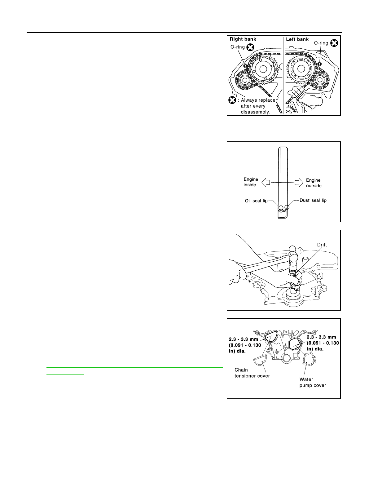
EM-78
[VQ35DE]
TIMING CHAIN
Revision: 2004 November 2004 FX35/FX45
16. Install new O-rings on rear timing chain case.
17. Install front oil seal on front timing chain case.
● Apply new engine oil to the oil seal edges.
● Install it so that each seal lip is oriented as shown in the fig-
ure.
● Using suitable drift, press-fit oil seal until it becomes flush with
front timing chain case end face.
● Make sure the garter spring is in position and seal lip is not
inverted.
18. Install water pump cover and chain tensioner cover to front tim-
ing chain case.
● Apply liquid gasket to front timing chain case front side as
shown in the figure with tube presser [SST: WS39930000 ( –
)].
Use Genuine RTV Silicone Sealant or equivalent. Refer to
GI-48, "
RECOMMENDED CHEMICAL PRODUCTS AND
SEALANTS".
SBIA0497E
SEM715A
PBIC0790E
SEM744GA
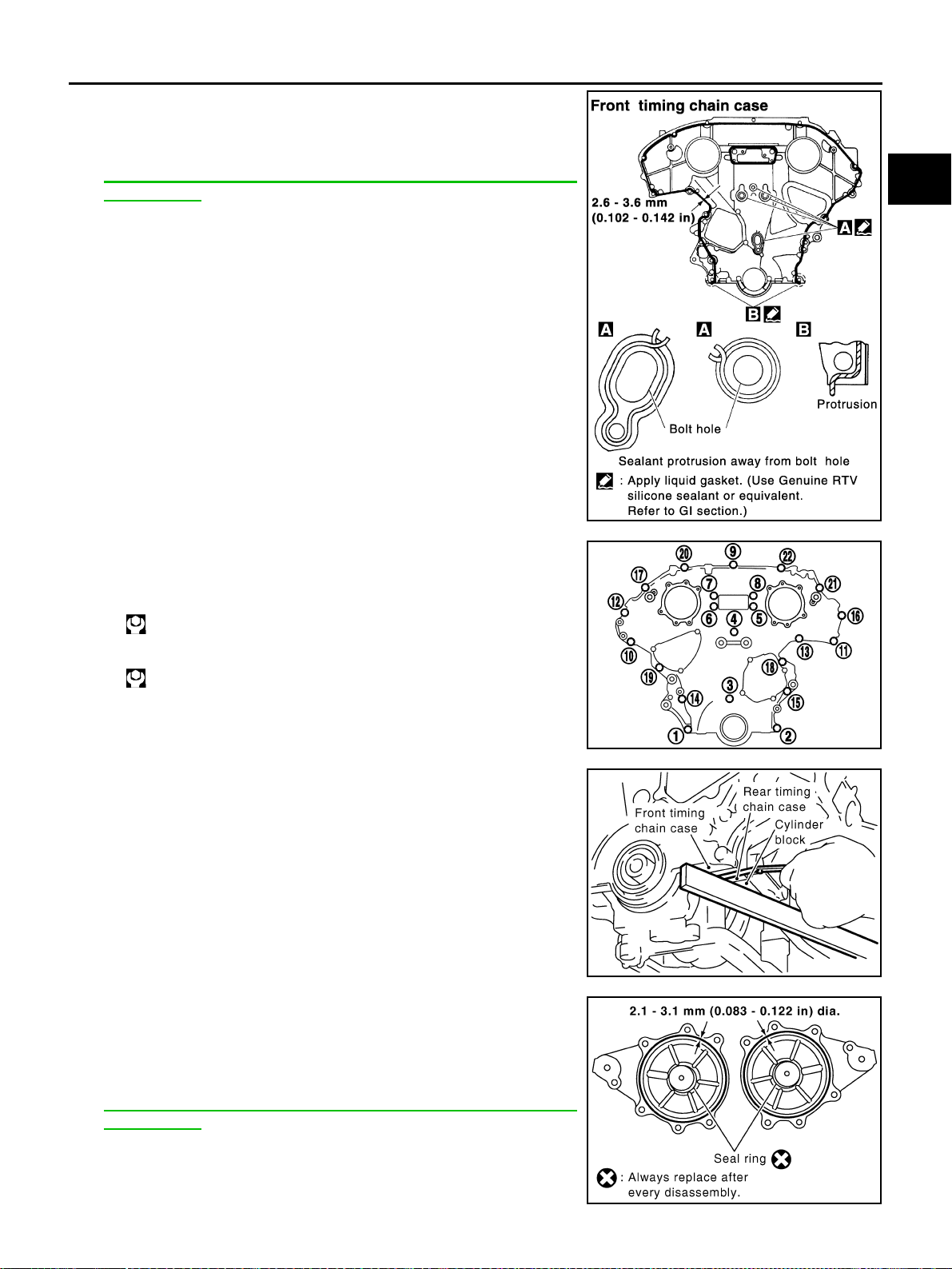
TIMING CHAIN
EM-79
[VQ35DE]
C
D
E
F
G
H
I
J
K
L
M
A
EM
Revision: 2004 November 2004 FX35/FX45
19. Install front timing chain case as follows:
a. Apply liquid gasket to front timing chain case back side as
shown in the figure with tube presser [SST: WS39930000 ( – )].
Use Genuine RTV Silicone Sealant or equivalent. Refer to
GI-48, "
RECOMMENDED CHEMICAL PRODUCTS AND
SEALANTS".
b. Install dowel pin on rear timing chain case into dowel pin hole on
front timing chain case.
c. Tighten bolts to the specified torque in order as shown in the fig-
ure.
d. After tightening, retighten them to specified torque in numerical
order shown in figure.
20. After installing front timing chain case, check the surface height
difference between the following parts on the oil pan mounting
surface.
● If not within specification, repeat the installation procedure.
21. Install right and left intake valve timing control covers as follows:
a. Install seal rings in shaft grooves.
b. Apply liquid gasket to intake valve timing control covers as
shown in the figure with tube presser [SST: WS39930000 ( – )].
Use Genuine RTV Silicone Sealant or equivalent. Refer to
GI-48, "
RECOMMENDED CHEMICAL PRODUCTS AND
SEALANTS".
PBIC1133E
8 mm (0.31 in) dia. bolts : 1, 2
: 28.4 N·m (2.9 kg-m, 21 ft-lb)
6 mm (0.24 in) dia. bolts : Except the above
: 12.7 N·m (1.3 kg-m, 9 ft-lb)
KBIA1303E
Standard
Front timing chain case to rear timing chain case:
–0.14 to 0.14 mm (–0.005 to 0.0055 in)
SEM943G
SBIA0492E
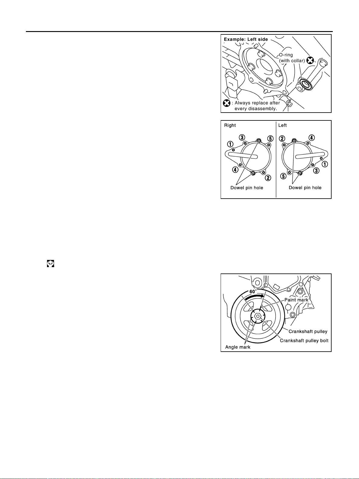
EM-80
[VQ35DE]
TIMING CHAIN
Revision: 2004 November 2004 FX35/FX45
c. Install collared O-ring in front cover engine oil hole (left and right
sides).
d. Being careful not to move seal ring from the installation groove,
align dowel pins on chain case with the holes to install intake
valve timing control covers.
e. Tighten bolts in the numerical order as shown in the figure.
22. Install crankshaft pulley as follows:
a. Fix crankshaft using ring gear stopper [SST: KV10117700 (J-44716)].
b. Install crankshaft pulley, taking care not to damage front oil seal.
● When press-fitting crankshaft pulley with a plastic hammer, tap on its center portion (not circumfer-
ence).
c. Tighten bolt.
d. Put a paint mark on crankshaft pulley aligning with angle mark
on crankshaft pulley bolt. Then, further retighten bolt by “60”
degrees (equivalent to one graduation).
23. Rotate crankshaft pulley in normal direction (clockwise when viewed from front) to confirm it turns
smoothly.
24. For the following operations, perform steps in the reverse order of removal.
NOTE:
If hydraulic pressure inside chain tensioner drops after removal/installation, slack in guide may generate a
pounding noise during and just after engine start. However, this does not indicate an unusualness. Noise
will stop after hydraulic pressure rises.
INSPECTION AFTER INSTALLATION
● Before starting engine, check the levels of engine coolant, lubrications and working fluid. If less than
required quantity, fill to the specified level.
● Run engine to check for unusual noise and vibration.
PBIC2045E
PBIC0918E
: 44.1 N·m (4.5 kg-m, 33 ft-lb)
SEM751G

TIMING CHAIN
EM-81
[VQ35DE]
C
D
E
F
G
H
I
J
K
L
M
A
EM
Revision: 2004 November 2004 FX35/FX45
● Warm up engine thoroughly to make sure there is no leakage of engine coolant, engine oil and working
fluid, fuel and exhaust gas.
● Bleed air from passages in pipes and tubes of applicable lines, such as in cooling system.
● After cooling down engine, again check amounts of engine coolant, engine oil and working fluid. Refill to
specified level, if necessary.
Summary of the inspection items:
Item Before starting engine Engine running After engine stopped
Engine coolant Level Leakage Level
Engine oil Level Leakage Level
Working fluid Level Leakage Level
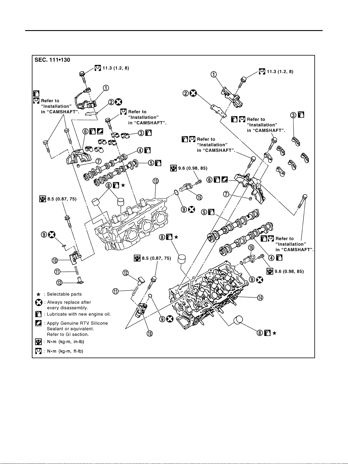
EM-82
[VQ35DE]
CAMSHAFT
Revision: 2004 November 2004 FX35/FX45
CAMSHAFT PFP:13001
Removal and Installation ABS00FPH
1.
Intake valve timing control solenoid
valve
2. Gasket 3. Camshaft bracket (No. 2 to No. 4)
4. Camshaft (EXH) 5. Camshaft (INT) 6. Camshaft bracket (No. 1)
7. Dowel pin 8. Valve lifter 9. O-ring
10. Chain tensioner 11. Spring 12. Plunger
13. Cylinder head (right bank) 14. Cylinder head (left bank) 15.
Camshaft position sensor (PHASE)
(right bank)
16.
Camshaft position sensor (PHASE)
(left bank)
SBIA0576E
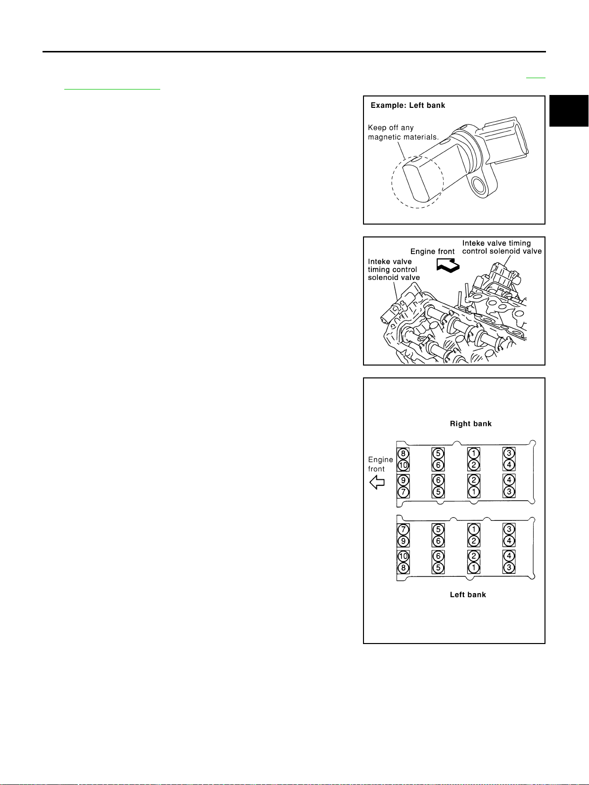
CAMSHAFT
EM-83
[VQ35DE]
C
D
E
F
G
H
I
J
K
L
M
A
EM
Revision: 2004 November 2004 FX35/FX45
REMOVAL
1. Remove front timing chain case, camshaft sprocket, timing chain and rear timing chain case. Refer to EM-
63, "TIMING CHAIN" .
2. If necessary, remove camshaft position sensor (PHASE) (right
and left banks) from cylinder head back side.
CAUTION:
● Handle carefully to avoid dropping and shocks.
● Do not disassemble.
● Do not allow metal powder to adhere to magnetic part at
sensor tip.
● Do not place sensors in a location where they are
exposed to magnetism.
3. Remove intake valve timing control solenoid valve from No.1
camshaft bracket.
4. Remove intake and exhaust camshaft brackets.
● Mark camshafts, camshaft brackets, and bolts so they are
placed in the same position and direction for installation.
● Equally loosen camshaft bracket bolts in several steps in the
reverse order as shown in the figure.
5. Remove camshaft.
6. Remove valve lifter.
● Identify installation positions, and store them without mixing them up.
KBIA1046E
SEM443GA
PBIC2050E
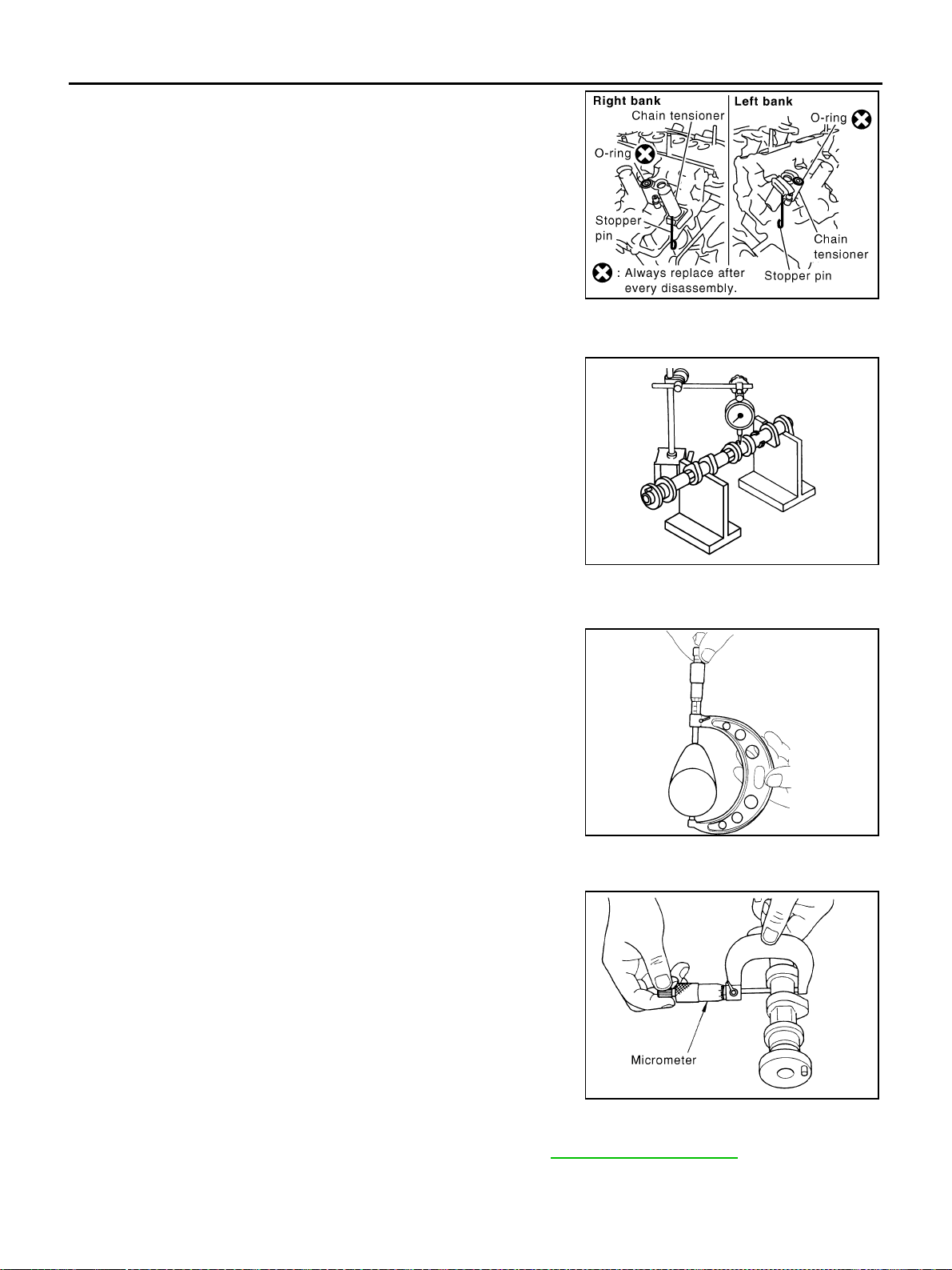
EM-84
[VQ35DE]
CAMSHAFT
Revision: 2004 November 2004 FX35/FX45
7. Remove secondary timing chain tensioner from cylinder head.
● Remove chain tensioner with its stopper pin attached.
NOTE:
Stopper pin was attached when secondary timing chain was
removed.
INSPECTION AFTER REMOVAL
Camshaft Runout
1. Put V block on precise flat bed, and support No. 2 and No. 4
journal of camshaft.
CAUTION:
Do not support journal No. 1 (on the side of camshaft
sprocket) because it has a different diameter from the other
three locations.
2. Set dial gauge vertically to No. 3 journal.
3. Turn camshaft to one direction with hands, and measure cam-
shaft runout on dial gauge. (Total indicator reading)
4. If it exceeds the standard, replace camshaft.
Camshaft Cam Height
1. Measure camshaft cam height.
2. If wear is beyond the limit, replace camshaft.
Camshaft Journal Oil Clearance
Outer Diameter of Camshaft Journal
Measure outer diameter of camshaft journal.
Inner Diameter of Camshaft Bracket
● Tighten camshaft bracket bolt with specified torque. Refer to EM-87, "INSTALLATION" .
SBIA0499E
Standard : Less than 0.05 mm (0.0020 in) PBIC0929E
Standard cam height (intake and exhaust)
: 44.865 - 45.055 mm (1.7663 - 1.7738 in)
Cam wear limit
: 0.2 mm (0.008 in)
EMQ0072D
Standard outer diameter:
No. 1: 25.935 - 25.955 mm (1.0211 - 1.0218 in)
No. 2, 3, 4: 23.445 - 23.465 mm (0.9230 - 0.9238 in)
PBIC0040E
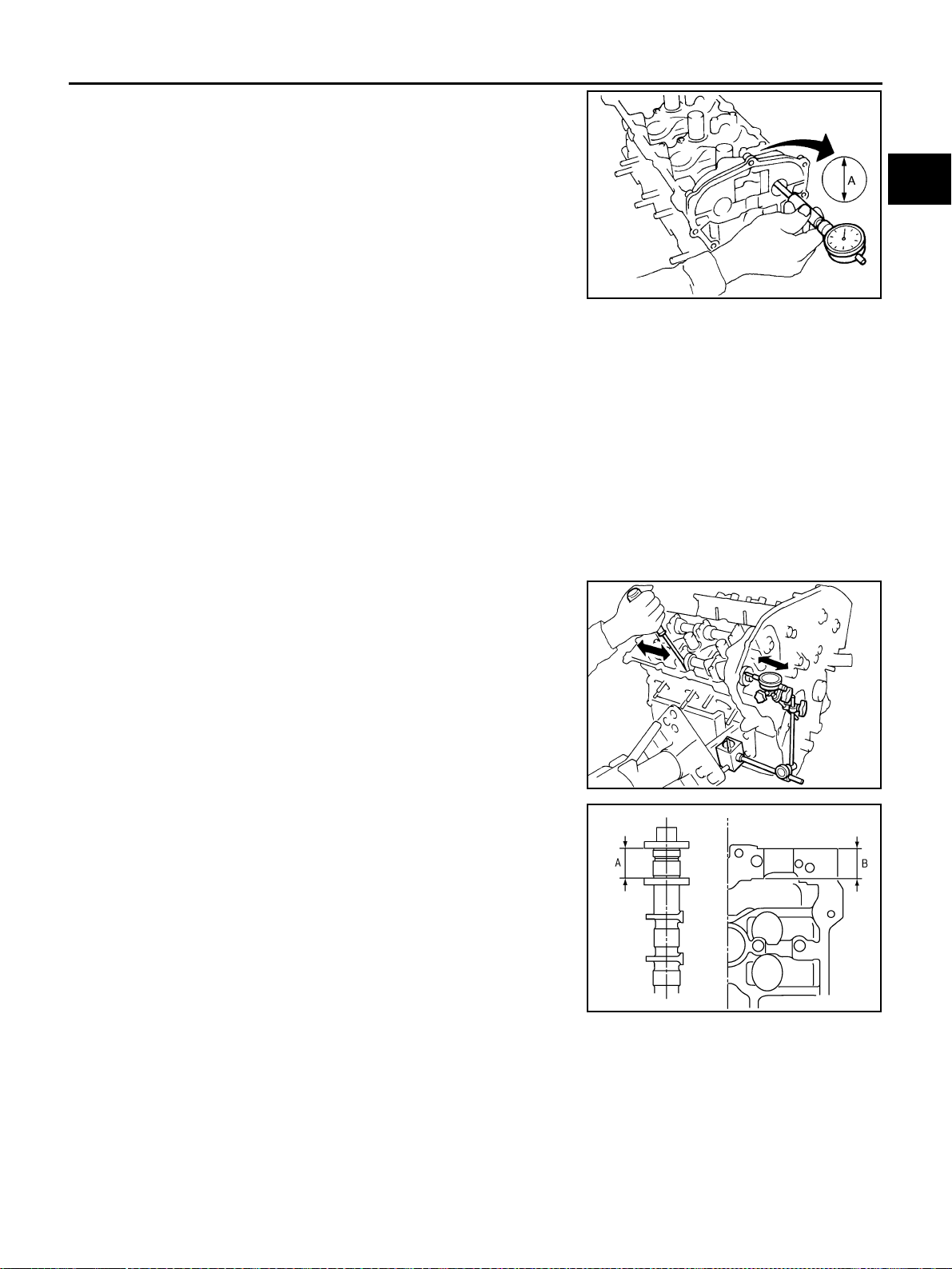
CAMSHAFT
EM-85
[VQ35DE]
C
D
E
F
G
H
I
J
K
L
M
A
EM
Revision: 2004 November 2004 FX35/FX45
● Using inside micrometer, measure inner diameter “A” of cam-
shaft bracket.
Calculation of Camshaft Journal Oil Clearance
(Journal oil clearance) = (inner diameter of camshaft bracket) – (outer diameter of camshaft journal).
If it exceeds the limit, replace either or both camshaft and cylinder head.
NOTE:
Camshaft brackets cannot be replaced as a single part, because it is machined together with cylinder head.
Replace whole cylinder head assembly.
Camshaft End Play
● Install dial indicator in thrust direction on front end of camshaft.
Measure end play of dial indicator when camshaft is moved for-
ward/backward (in direction to axis).
● Measure the following parts if out of the limit.
– Dimension “A” for camshaft No. 1 journal
– Dimension “B” for cylinder head No. 1 journal
● Refer to the standards above, and then replace camshaft and/or
cylinder head.
Camshaft Sprocket Runout
1. Put V-block on precise flat table, and support No. 2 and No. 4 journal of camshaft.
CAUTION:
Do not support journal No. 1 (on the side of camshaft sprocket) because it has a different diameter
from the other three locations.
Standard inner diameter:
No. 1 : 26.000 - 26.021 mm (1.0236 - 1.0244 in)
No. 2, 3, 4 : 23.500 - 23.521 mm (0.9252 - 0.9260 in)
PBIC1645E
Standard:
No. 1 : 0.045 - 0.086 mm (0.0018 - 0.0034 in)
No. 2, 3, 4 : 0.035 - 0.076 mm (0.0014 - 0.0030 in)
Limit : 0.15 mm (0.0059 in)
Standard : 0.115 - 0.188 mm (0.0045 - 0.0074 in)
Limit : 0.24 mm (0.0094 in)
SEM864E
Standard : 27.500 - 27.548 mm (1.0827 - 1.0846 in)
Standard : 27.360 - 27.385 mm (1.0772 - 1.0781 in)
KBIA2404J
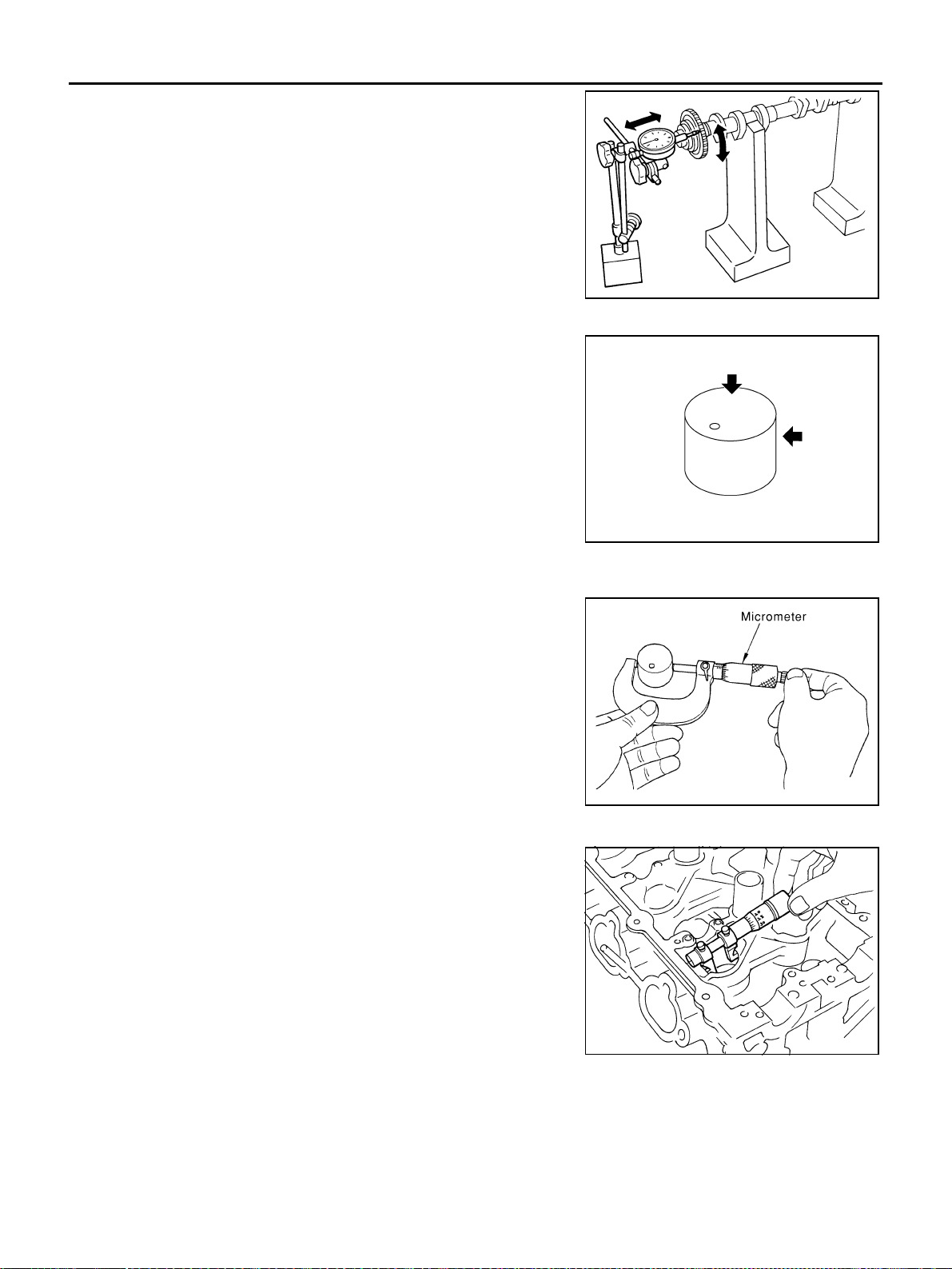
EM-86
[VQ35DE]
CAMSHAFT
Revision: 2004 November 2004 FX35/FX45
2. Measure camshaft sprocket runout with dial indicator. (Total indi-
cator reading)
● If it exceeds the limit, replace camshaft sprocket.
Valve Lifter
Check if surface of valve lifter has any wear or cracks.
● If anything above is found, replace valve lifter.
Valve Lifter Clearance
Outer Diameter of Valve Lifter
Measure outer diameter at 1/2 height of valve lifter with micrometer
since valve lifter is in barrel shape.
Valve Lifter Hole Diameter
Using inside micrometer, measure diameter of valve lifter hole of cyl-
inder head.
Calculation of Valve Lifter Clearance
(Valve lifter clearance) = (hole diameter of valve lifter) – (outer diameter of valve lifter).
If it exceeds the standard, referring to each standard of valve lifter outer diameter and valve lifter hole diame-
ter, replace either or both valve lifter and cylinder head.
Limit : 0.15 mm (0.0059 in)
PBIC0930E
KBIA0182E
Valve lifter outer diameter (Intake and exhaust)
: 33.977 - 33.987 mm (1.3377 - 1.3381 in)
JEM798G
Standard (Intake and exhaust)
: 34.000 - 34.016 mm (1.3386 - 1.3392 in)
SEM867E
Standard (Intake and exhaust)
: 0.013 - 0.039 mm (0.0005 - 0.0015 in)
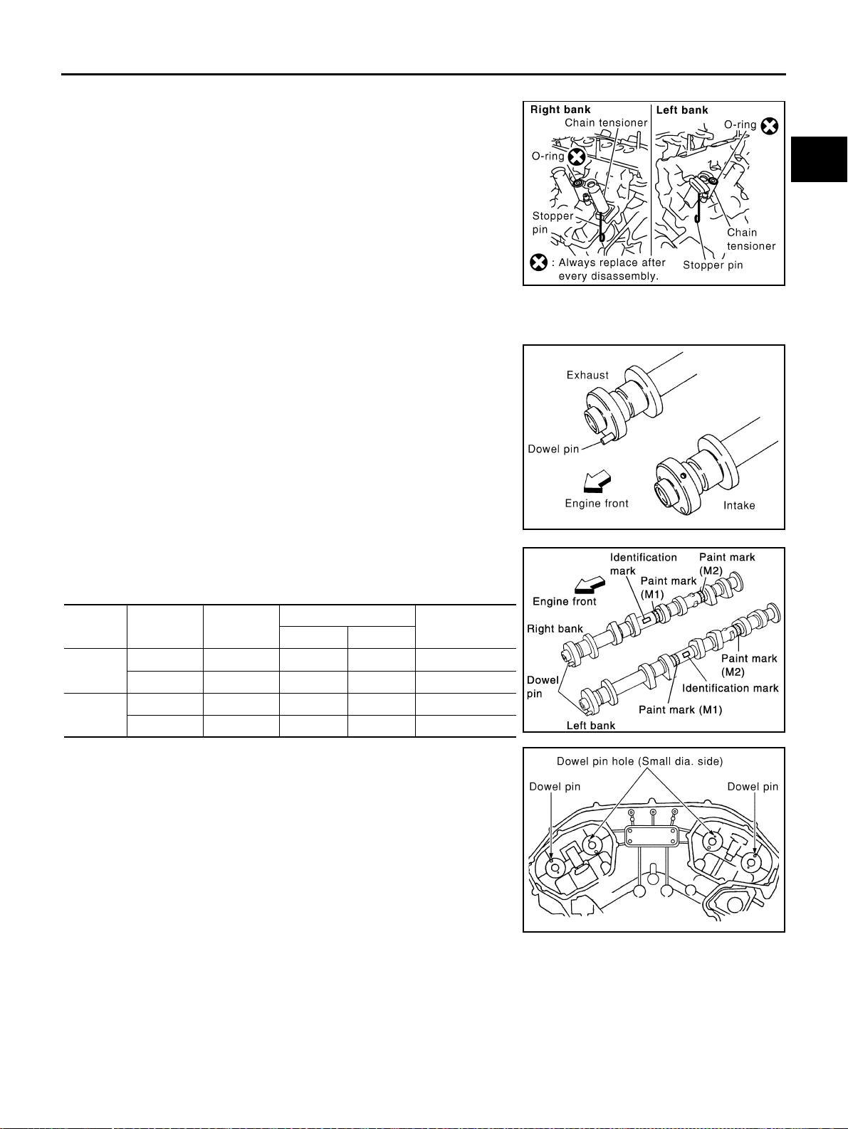
CAMSHAFT
EM-87
[VQ35DE]
C
D
E
F
G
H
I
J
K
L
M
A
EM
Revision: 2004 November 2004 FX35/FX45
INSTALLATION
1. Install secondary chain tensioners on both sides of cylinder
head.
● Install chain tensioner with its stopper pin attached.
● Install tensioner with sliding part facing downward on right-
side cylinder head, and with sliding part facing upward on left-
side cylinder head.
● Install new O-ring as shown in the figure.
2. Install valve lifter.
● Install it in the original position.
3. Install camshafts.
● Install camshaft with dowel pin attached to its front end face
on exhaust side.
● Follow your identification marks made during removal, or fol-
low the identification marks that are present on new cam-
shafts for proper placement and direction.
● Install camshaft so that dowel pin hole and dowel pin on front
end face are positioned as shown in figure. (No. 1 cylinder
TDC on its compression stroke)
NOTE:
Large- and small-pin holes are located on front end face of
intake camshaft, at intervals of 180°. Face small dia. side pin
hole upward (in cylinder head upper face direction).
SBIA0499E
KBIA1071E
Bank INT/EXH Dowel pin
Paint marks
Identification
mark
M1 M2
Right
INT No Pink No RE
EXH Yes No Orange RE
Left
INT No Pink No LH
EXH Yes No Orange LH KBIA1009E
KBIA1072E
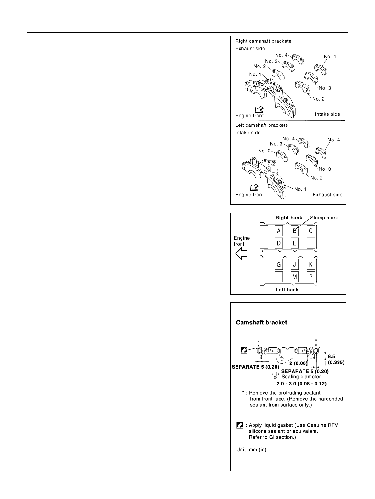
EM-88
[VQ35DE]
CAMSHAFT
Revision: 2004 November 2004 FX35/FX45
4. Install camshaft brackets.
● Remove foreign material completely from camshaft bracket
backside and from cylinder head installation face.
● Install camshaft bracket in original position and direction as
shown in the figure.
● Install No. 2 to 4 camshaft brackets aligning stamp marks as
shown in the figure.
NOTE:
There are no identification marks indicating left and right for
No. 1 camshaft bracket.
● Apply sealant to mating surface of No. 1 camshaft bracket as
shown on right and left banks.
Use Genuine RTV Silicone Sealant or equivalent. Refer to
GI-48, "
RECOMMENDED CHEMICAL PRODUCTS AND
SEALANTS" .
PBIC2051E
PBIC2052E
PBIC0915E
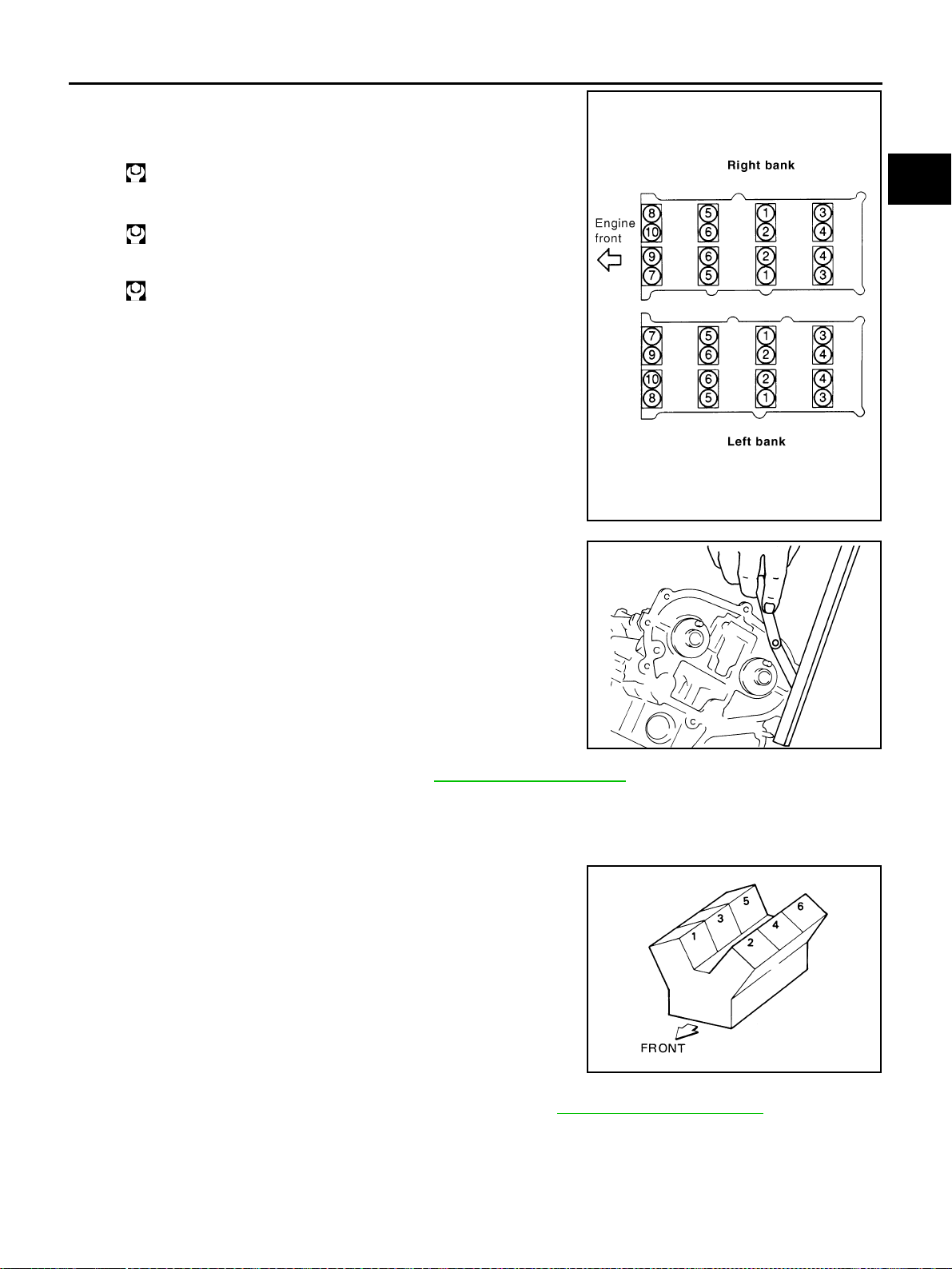
CAMSHAFT
EM-89
[VQ35DE]
C
D
E
F
G
H
I
J
K
L
M
A
EM
Revision: 2004 November 2004 FX35/FX45
5. Tighten camshaft brackets in the following steps, in numerical
order as shown in the figure.
a. Tighten No. 7 to 10, then tighten No. 1 to 6 in order as shown.
b. Tighten all bolts in numerical order as shown.
c. Tighten all bolts in the numerical order as shown.
CAUTION:
After tightening mounting bolts of No. 1 camshaft brackets
(No. 1), be sure to wipe off excessive liquid gasket from the
parts list below.
● Mating surface of rocker cover
● Mating surface of rear timing chain case
6. Measure difference in levels between front end faces of No. 1
camshaft bracket and cylinder head.
● If measurement is outside the specified range, re-install cam-
shaft and camshaft bracket.
7. Inspect and adjust valve clearance. Refer to EM-89, "
Valve Clearance" .
8. Install in the reverse order of removal after this step.
Valve Clearance ABS004XG
INSPECTION
Perform inspection as follows after removal, installation or replace-
ment of camshaft or valve-related parts, or if there is unusual engine
conditions regarding valve clearance.
1. Remove right and left rocker covers with power tool. Refer to EM-51, "
ROCKER COVER" .
2. Measure valve clearance as below:
a. Set No. 1 cylinder at TDC of its compression stroke.
: 1.96 N·m (0.20 kg-m, 1 ft-lb)
: 5.88 N·m (0.60 kg-m, 4 ft-lb)
: 10.4 N·m (1.1 kg-m, 8 ft-lb)
PBIC2050E
Standard : –0.14 to 0.14 mm (–0.0055 to 0.0055 in)
EMQ0044D
SEM713A
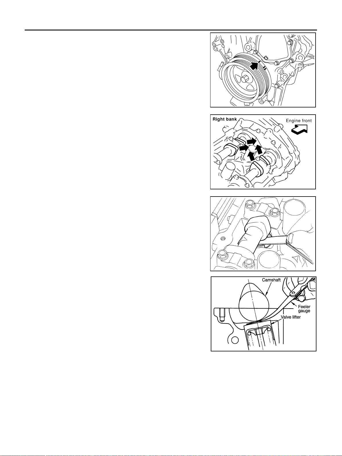
EM-90
[VQ35DE]
CAMSHAFT
Revision: 2004 November 2004 FX35/FX45
● Rotate crankshaft pulley clockwise to align timing mark
(grooved line without color) with timing indicator.
● Make sure No. 1 cylinder intake and exhaust cam nose is fac-
ing in direction as shown in figure.
● If not, rotate crankshaft pulley 360° clockwise (when viewed
from front).
b. Using a feeler gauge, measure valve clearance.
*: Approximately 80°C (176°F) (Reference data)
KBIA1717J
SEM418G
Valve clearance standard:
Cold Intake : 0.26 - 0.34 mm (0.010 - 0.013 in)
Exhaust : 0.29 - 0.37 mm (0.011 - 0.015 in)
Hot* Intake : 0.304 - 0.416 mm (0.012 - 0.016 in)
Exhaust : 0.308 - 0.432 mm (0.012 - 0.016 in)
SEM139D
KBIA0185E
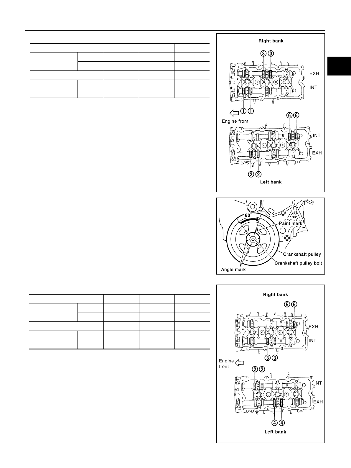
CAMSHAFT
EM-91
[VQ35DE]
C
D
E
F
G
H
I
J
K
L
M
A
EM
Revision: 2004 November 2004 FX35/FX45
● No. 1 cylinder at compression TDC
c. Rotate crankshaft by 240° clockwise (when viewed from front) to
align No. 3 cylinder at TDC of its compression stroke.
NOTE:
Crankshaft pulley mounting bolt flange has a stamped line every
60°. They can be used as a guide to rotation angle.
● No. 3 cylinder at compression TDC
Measuring position (right bank) No. 1 CYL. No. 3 CYL. No. 5 CYL.
No. 1 cylinder at
TDC
EXH ×
INT ×
Measuring position (left bank) No. 2 CYL. No. 4 CYL. No. 6 CYL.
No. 1 cylinder at
TDC
INT ×
EXH ×
PBIC2054E
SEM751G
Measuring position (right bank) No. 1 CYL. No. 3 CYL. No. 5 CYL.
No. 3 cylinder at
TDC
EXH ×
INT ×
Measuring position (left bank) No. 2 CYL. No. 4 CYL. No. 6 CYL.
No. 3 cylinder at
TDC
INT ×
EXH ×
PBIC2055E
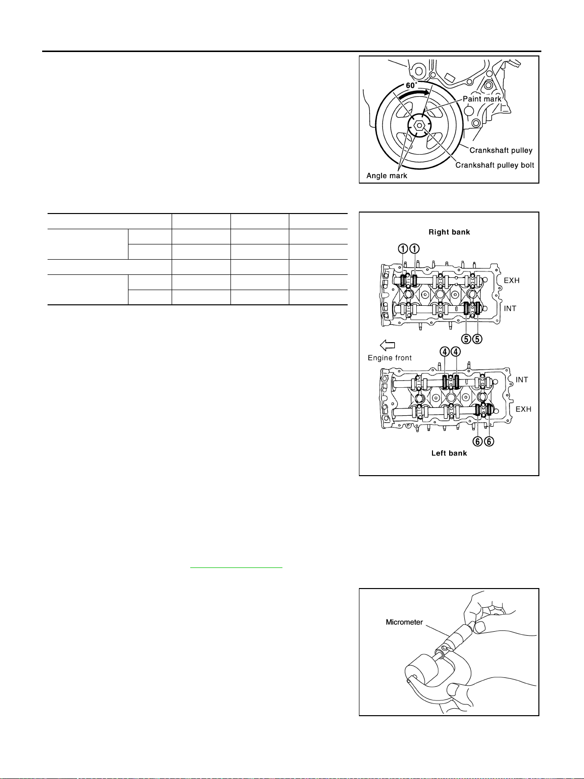
EM-92
[VQ35DE]
CAMSHAFT
Revision: 2004 November 2004 FX35/FX45
d. Rotate crankshaft by 240 degrees clockwise (when viewed from
engine front) to align No. 5 cylinder at TDC of compression
stroke.
● No. 5 cylinder at compression TDC
CAUTION:
If inspection was carried out with cold engine, make sure
values with fully warmed up engine are still within speci-
fications.
3. For measurements that are outside the specified range, perform adjustment below.
ADJUSTMENT
● Perform adjustment depending on selected head thickness of valve lifter.
● The specified valve lifter thickness is the dimension at normal temperatures. Ignore dimensional differ-
ences caused by temperature. Use the specifications for hot engine condition to adjust.
1. Remove camshaft. Refer to EM-83, "
REMOVAL" .
2. Remove valve lifters at the locations that are outside the standard.
3. Measure the center thickness of the removed valve lifters with a
micrometer.
4. Use the equation below to calculate valve lifter thickness for replacement.
SEM751G
Measuring position (right bank) No. 1 CYL. No. 3 CYL. No. 5 CYL.
No. 5 cylinder at
TDC
EXH ×
INT ×
Measuring position (left bank) No. 2 CYL. No. 4 CYL. No. 6 CYL.
No. 5 cylinder at
TDC
INT ×
EXH ×
PBIC2056E
KBIA0057E
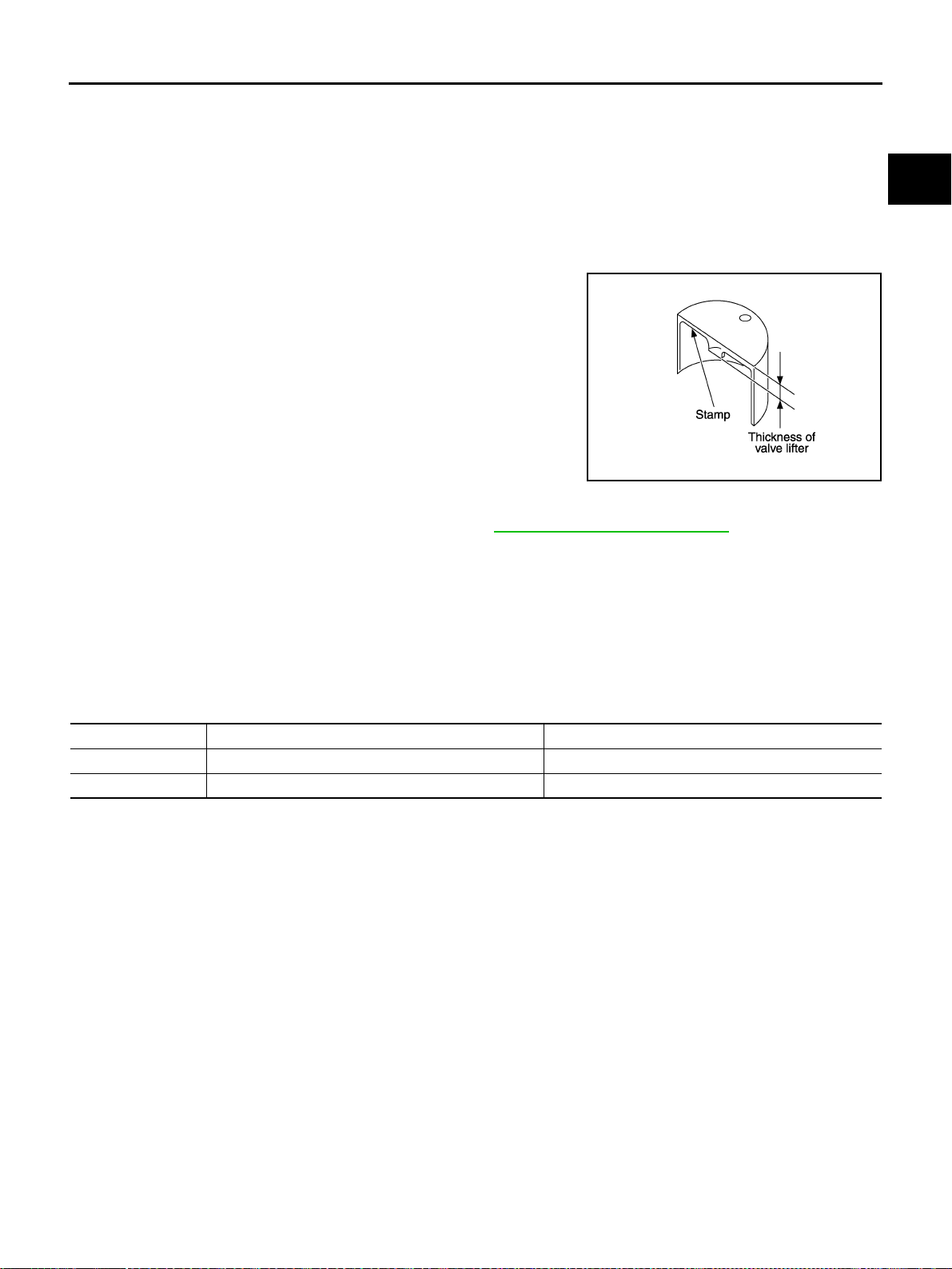
CAMSHAFT
EM-93
[VQ35DE]
C
D
E
F
G
H
I
J
K
L
M
A
EM
Revision: 2004 November 2004 FX35/FX45
● Valve lifter thickness calculation:
Thickness of replacement valve lifter = t1+ (C1 - C2)
t1 = Thickness of removed valve lifter
C1 = Measured valve clearance
C2= Standard valve clearance:
● Thickness of a new valve lifter can be identified by stamp
marks on the reverse side (inside the cylinder).
Stamp mark 788U or 788R indicates 7.88 mm (0.3102 in) in
thickness.
NOTE:
2 types of stamp marks are used for parallel setting and for
manufacturer identification.
Available thickness of valve lifter: 27 sizes with range 7.88 to 8.40 mm (0.3102 to 0.3307 in) in steps of 0.02
mm (0.0008 in) (when manufactured at factory). Refer to EM-149, "
Available Valve Lifter" .
5. Install selected valve lifter.
6. Install camshaft.
7. Manually turn crankshaft pulley a few turns.
8. Make sure valve clearances for cold engine are within specifications by referring to the specified values.
9. After completing the repair, check valve clearances again with the specifications for warmed engine. Make
sure the values are within specifications.
Valve clearance:
Unit: mm (in)
*: Approximately 80°C (176°F)
Intake : 0.30 mm (0.012 in)*
Exhaust : 0.33 mm (0.013 in)*
*: Approximately 20°C (68°F)
KBIA0119E
Items Cold Hot * (reference data)
Intake 0.26 - 0.34 (0.010 - 0.013) 0.304 - 0.416 (0.012 - 0.016)
Exhaust 0.29 - 0.37 (0.011 - 0.015) 0.308 - 0.432 (0.012 - 0.016)
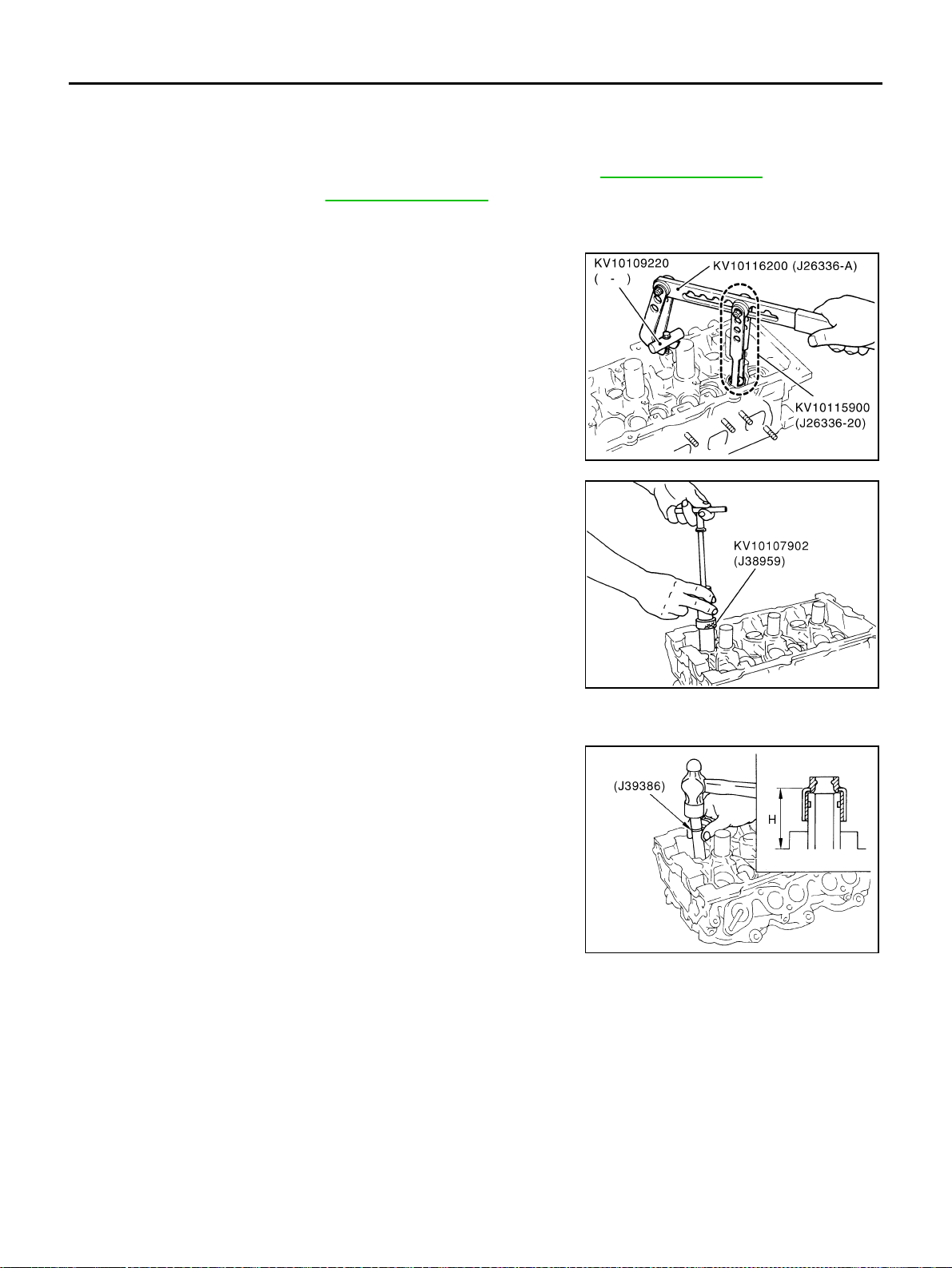
EM-94
[VQ35DE]
OIL SEAL
Revision: 2004 November 2004 FX35/FX45
OIL SEAL PFP:00100
Removal and Installation of Valve Oil Seal ABS004X4
REMOVAL
1. Remove camshaft relating to valve oil seal to be removed. Refer to EM-82, "CAMSHAFT" .
2. Remove valve lifters. Refer to EM-82, "
CAMSHAFT" .
3. Turn crankshaft until the cylinder requiring new oil seals is at TDC. This will prevent valve from dropping
into cylinder.
4. Using valve spring compressor, attachment and adapter (SST),
remove valve collet with magnet hand. Then remove valve
spring and valve spring seat.
5. Remove valve oil seal using valve oil seal puller (SST).
INSTALLATION
1. Apply engine oil on new valve oil seal joint and seal lip.
2. Using valve oil seal drift (SST), press fit valve seal to height “H”
shown in the figure.
NOTE:
Dimension “H”: Height measured before valve spring seat instal-
lation
3. Perform steps in the reverse order of removal for the following operations.
PBIC1803E
PBIC0884E
Intake and exhaust : 14.3 - 14.9 mm (0.563 - 0.587 in)
PBIC0802E
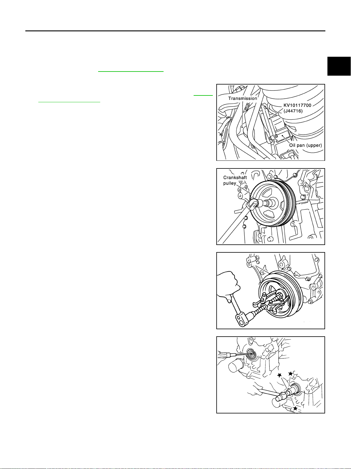
OIL SEAL
EM-95
[VQ35DE]
C
D
E
F
G
H
I
J
K
L
M
A
EM
Revision: 2004 November 2004 FX35/FX45
Removal and Installation of Front Oil Seal ABS004X5
REMOVAL
1. Remove the following parts:
● Front engine undercover (With power tool)
● Drive belt; Refer to EM-15, "DRIVE BELTS" .
2. Remove crankshaft pulley with the following procedure:
a. Remove rear cover plate (2WD) or starter motor (AWD) and set
ring gear stopper (SST) as shown in the figure. Refer to SC-10,
"STARTING SYSTEM" .
b. Loosen crankshaft pulley bolt and locate bolt seating surface as
10 mm (0.39 in) from its original position.
CAUTION:
Do not remove crankshaft pulley bolt as it will be used as a
supporting point for suitable puller.
c. Place suitable puller tab on holes of crankshaft pulley, and pull
crankshaft pulley through.
CAUTION:
Do not put suitable puller tab on crankshaft pulley periph-
ery, as this will damage internal damper.
3. Remove front oil seal using a suitable tool.
CAUTION:
Be careful not to damage front timing chain case and crank-
shaft.
PBIC1098E
PBIC1103E
EMQ0477D
SEM829E
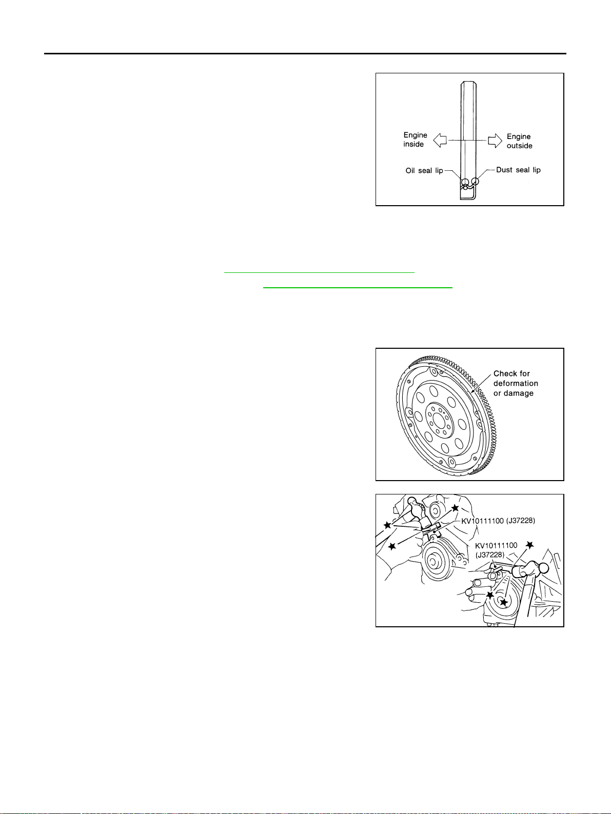
EM-96
[VQ35DE]
OIL SEAL
Revision: 2004 November 2004 FX35/FX45
INSTALLATION
1. Apply engine oil on new front oil seal.
2. Using a suitable drift, press fit until the height of front oil seal is
level with the mounting surface.
● Suitable drift: outer diameter 59 mm (2.32 in), inner diameter
49 mm (1.93 in).
CAUTION:
Press fit straight and avoid causing burrs or tilting oil
seal.
3. Perform steps in the reverse order of removal for the following operations.
Removal and Installation of Rear Oil Seal ABS004X6
REMOVAL
1. Remove oil pan (upper). Refer to EM-30, "OIL PAN AND OIL STRAINER" .
2. Remove transmission assembly. Refer to AT-266, "
TRANSMISSION ASSEMBLY" .
3. Remove drive plate with power tool. Fix crankshaft with a ring gear stopper [SST: KV1011770 (J-44716)],
and remove mounting bolts.
● Loosen mounting bolts in diagonal order.
CAUTION:
● Do not disassemble drive plate.
● Never place drive plate with signal plate facing down.
● When handling signal plate, take care not to damage or
scratch it.
● Handle signal plate in a manner that prevents it from
becoming magnetized.
4. Use a seal cutter (SST) to cut away liquid gasket and remove
rear oil seal retainer.
CAUTION:
Be careful not to damage mounting surface.
NOTE:
Rear oil seal and retainer form a single part and are handled as
an assembly.
INSTALLATION
1. Remove old liquid gasket on mating surface of cylinder block and oil pan using scraper.
SEM715A
SEM760G
SEM830E
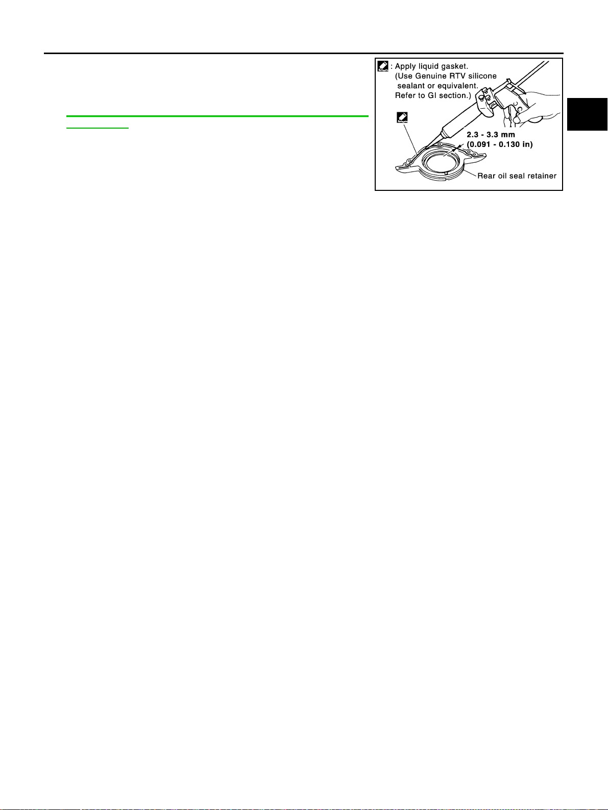
OIL SEAL
EM-97
[VQ35DE]
C
D
E
F
G
H
I
J
K
L
M
A
EM
Revision: 2004 November 2004 FX35/FX45
2. Apply new engine oil to the oil and dust seal lips.
3. Apply liquid gasket to rear oil seal retainer with tube presser
[SST: WS39930000 ( – )] as shown in the figure.
Use Genuine RTV Silicone Sealant or equivalent. Refer to
GI-48, "
RECOMMENDED CHEMICAL PRODUCTS AND
SEALANTS" .
● Assembly should be done within 5 minutes after coating.
4. Install rear oil seal retainer to cylinder block.
5. Perform steps in the reverse order of removal for the following operations.
PBIC0922E
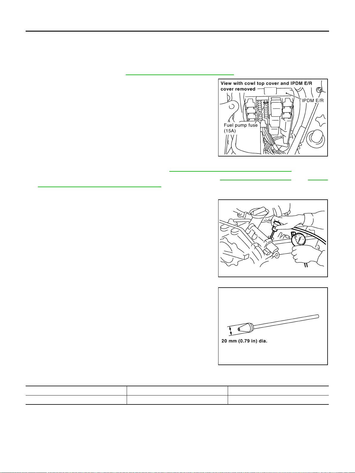
EM-98
[VQ35DE]
CYLINDER HEAD
Revision: 2004 November 2004 FX35/FX45
CYLINDER HEAD PFP:11041
On-Vehicle Service ABS004X7
CHECKING COMPRESSION PRESSURE
1. Warm up engine thoroughly. Then, stop it.
2. Release fuel pressure. Refer to EC-51, "
FUEL PRESSURE RELEASE" .
3. Disconnect fuel pump fuse to avoid fuel injection during mea-
surement.
4. Remove engine cover with power tool. Refer to EM-19, "
INTAKE MANIFOLD COLLECTOR" .
5. Remove ignition coil and spark plug from each cylinder. Refer to EM-42, "
IGNITION COIL" and EM-43,
"SPARK PLUG (PLATINUM-TIPPED TYPE)" .
6. Connect engine tachometer (not required in use of CONSULT-ll).
7. Install compression gauge with compression gauge adapter
(commercial service tool) onto spark plug hole.
● Use compression gauge adapter whose picking up end
inserted to spark plug hole is smaller than 20 mm (0.79 in) in
diameter. Otherwise, it may be caught by cylinder head during
removal.
8. With accelerator pedal fully depressed, turn ignition switch to
“START” for cranking. When gauge pointer stabilizes, read the
compression pressure and engine rpm. Perform these steps to
check each cylinder.
Compression pressure:
Unit: kPa (kg/cm
2
, psi) /rpm
CAUTION:
Always use a fully changed battery to obtain specified engine speed.
● If engine speed is out of specified range, check battery liquid for proper gravity. Check engine speed
again with normal battery gravity.
SBIA0466E
PBIC0900E
SBIA0533E
Standard Minimum Deference limit between cylinders
1,275 (13.0, 185) / 300 981 (10.0, 142) / 300 98 (1.0, 14) / 300
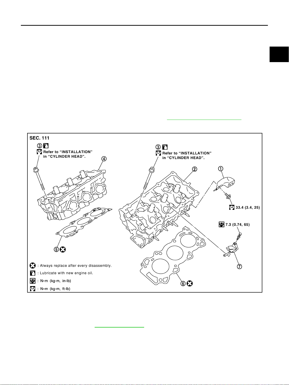
CYLINDER HEAD
EM-99
[VQ35DE]
C
D
E
F
G
H
I
J
K
L
M
A
EM
Revision: 2004 November 2004 FX35/FX45
● If compression pressure is below minimum value, check valve clearances and parts associated with
combustion chamber (valve, valve seat, piston, piston ring, cylinder bore, cylinder head, cylinder head
gasket). After the checking, measure compression pressure again.
● If some cylinders have low compression pressure, pour small amount of engine oil into spark plug hole
of cylinder to re-check it for compression.
– If the added engine oil improves the compression, piston rings may be worn out or damaged. Check
piston rings and replace if necessary.
– If the compression pressure remains at low level despite the addition of engine oil, valves may be mal-
functioning. Check valves for damage. Replace valve or valve seat accordingly.
● If two adjacent cylinders have respectively low compression pressure and their compression remains
low even after the addition of engine oil, gaskets are leaking. In such a case, replace cylinder head gas-
kets.
9. After inspection is completed, install removed parts.
10. Start engine, and confirm that engine runs smoothly.
11. Perform trouble diagnosis. If DTC appears, erase it. Refer toEC-77, "
TROUBLE DIAGNOSIS" .
Removal and Installation ABS004X8
REMOVAL
1. Remove camshaft. Refer to EM-82, "CAMSHAFT" .
NOTE:
It is also possible to perform the following steps 2 and 3 just before removing camshaft.
2. Temporarily fit front suspension member to support engine.
CAUTION:
Temporary fitting means the status that engine is adequately stable though hoist is released from
hanging.
1. Engine rear lower slinger 2. Cylinder head (left bank) 3. Cylinder head bolt
4. Cylinder head (right bank) 5. Cylinder head gasket (right bank) 6. Cylinder head gasket (left bank)
7. Oil level gauge guide
SBIA0581E
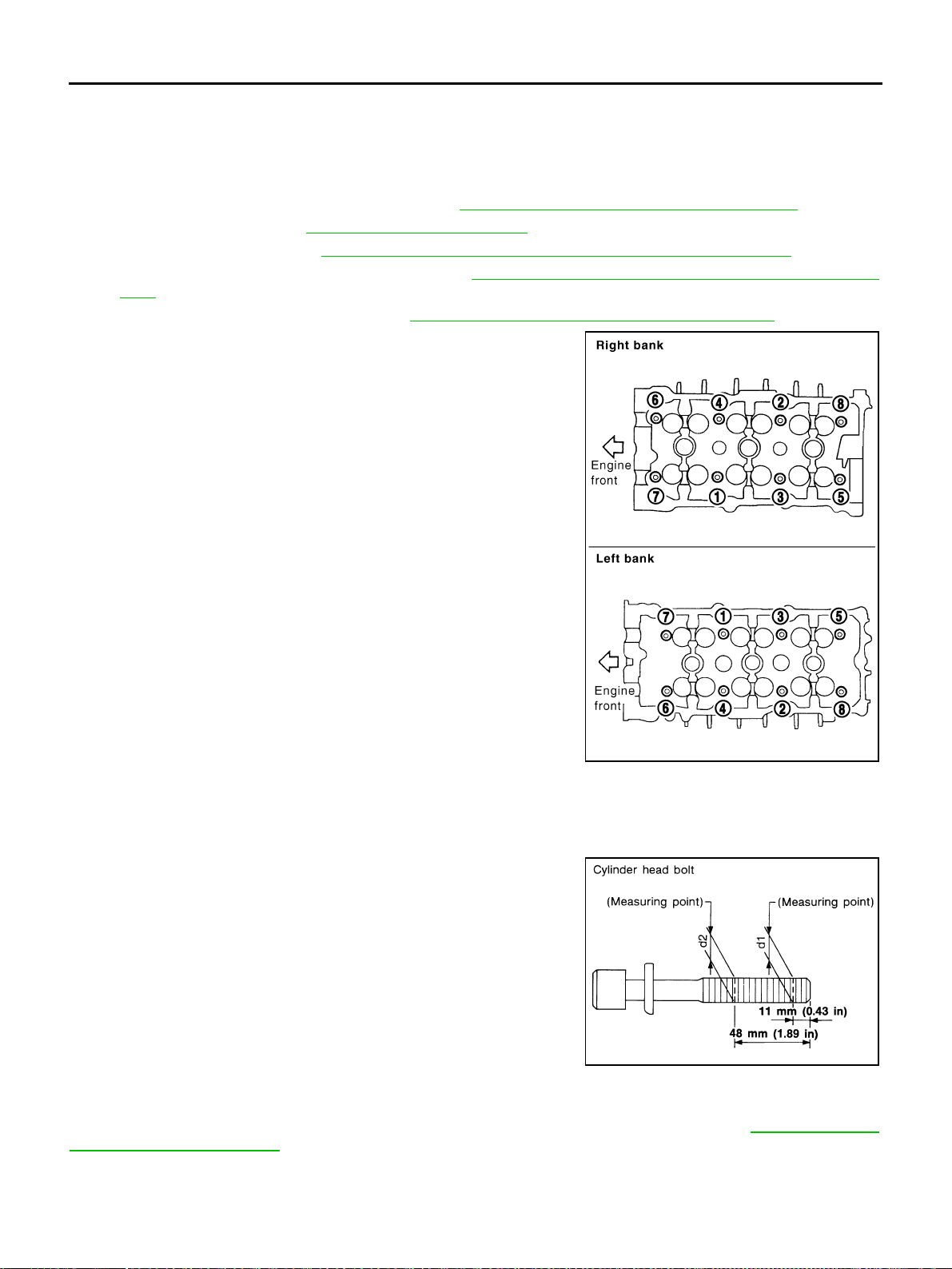
EM-100
[VQ35DE]
CYLINDER HEAD
Revision: 2004 November 2004 FX35/FX45
NOTE:
At the time of the start of this procedure front suspension member is removed, and cylinder head is
hanged by hoist with engine slinger installed.
3. Release hoist from hanging, then remove engine slinger.
4. Remove the following components and related parts:
● Fuel tube and fuel injector assembly. Refer to EM-45, "FUEL INJECTOR AND FUEL TUBE" .
● Intake manifold. Refer to EM-24, "INTAKE MANIFOLD" .
● Exhaust manifold. Refer to EM-26, "EXHAUST MANIFOLD AND THREE WAY CATALYST" .
● Water inlet and thermostat assembly. Refer to CO-26, "WATER INLET AND THERMOSTAT ASSEM-
BLY" .
● Water outlet and water piping. Refer to CO-28, "WATER OUTLET AND WATER PIPING" .
5. Remove cylinder head loosening bolts with power tool in reverse
order shown in the figure and using cylinder head bolt wrench
(commercial service tool).
6. Remove cylinder head gaskets.
INSPECTION AFTER REMOVAL
Outer Diameter of Cylinder Head Bolts
● Cylinder head bolts are tightened by plastic zone tightening
method. Whenever the size difference between d1 and d2
exceeds the limit, replace them with new one.
● If reduction of outer diameter appears in a position other than
d2, use it as d2 point.
Cylinder Head Distortion
NOTE:
When performing this inspection, cylinder block distortion should be also checking. Refer to EM-139, "
CYLIN-
DER BLOCK DISTORTION" .
1. Using scraper, wipe off oil, scale, gasket, sealant and carbon deposits from surface of cylinder head.
CAUTION:
Do not allow gasket fragments to enter engine oil or engine coolant passages.
PBIC2057E
Limit (d1 - d2) : 0.11 mm (0.0043 in)
SEM957E
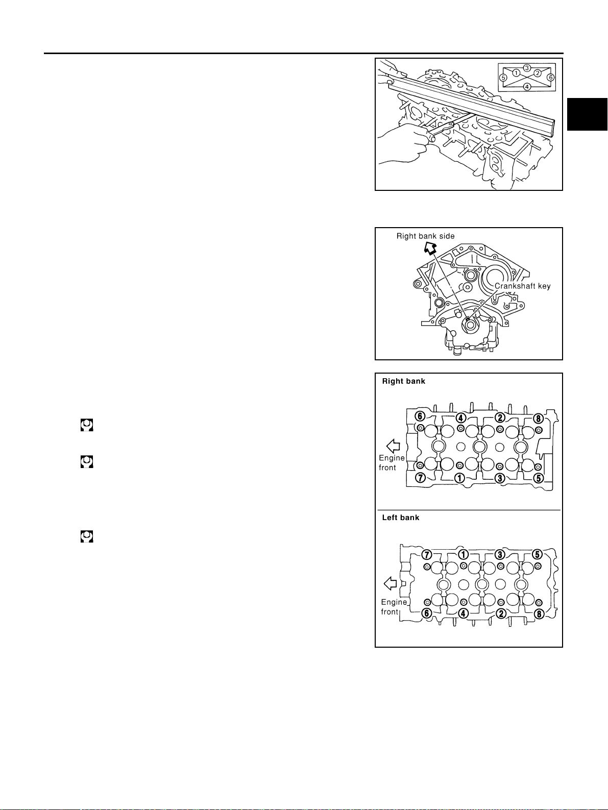
CYLINDER HEAD
EM-101
[VQ35DE]
C
D
E
F
G
H
I
J
K
L
M
A
EM
Revision: 2004 November 2004 FX35/FX45
2. At each of several locations on bottom surface of cylinder head,
measure distortion in six directions.
● If it exceeds the limit, replace cylinder head.
INSTALLATION
1. Install cylinder head gasket.
2. Turn crankshaft until No. 1 piston is set at TDC on the compres-
sion stroke.
● Crankshaft key should line up with the right bank cylinder cen-
ter line as shown.
3. Install cylinder head follow the steps below to tighten cylinder
head bolts in the order shown in figure.
a. Tighten all bolts.
b. Completely loosen.
CAUTION:
In step “b”, loosen bolts in the reverse order of that indi-
cated in figure.
c. Tighten all bolts.
Limit : 0.1 mm (0.004 in)
SEM861E
SEM532G
: 98.1 N·m (10 kg-m, 72 ft-lb)
: 0 N·m (0 kg-m, 0 ft-lb)
: 39.2 N·m (4.0 kg-m, 29 ft-lb)
PBIC2057E
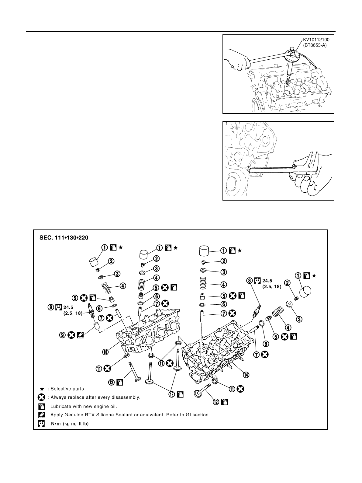
EM-102
[VQ35DE]
CYLINDER HEAD
Revision: 2004 November 2004 FX35/FX45
d. Turn all bolts “90” degrees clockwise (angle tightening).
e. Turn all bolts “90” degrees clockwise again [target: 90 degrees
(angle tightening)].
CAUTION:
Check and confirm the tightening angle by using angle
wrench (SST) and cylinder head bolt wrench (commercial
service tool). Avoid judgment by visual inspection without
SST.
● Check tightening angle indicated on angle wrench (SST) indi-
cator plate.
4. After installing cylinder head, measure distance between front
end faces of cylinder block and cylinder head (left and right
banks).
● If measurement is outside the specified range, re-install cylin-
der head.
5. Perform steps in reverse order of removal for the following operations.
Disassembly and Assembly ABS004X9
PBIC0888E
Standard : 14.1 - 14.9 mm (0.555 - 0.587 in)
EMQ0662D
1. Valve lifter 2. Valve collet 3. Valve spring retainer
4. Valve spring 5. Valve oil seal 6. Valve spring seat
7. Valve guide 8. Spark plug 9. Spark plug tube
PBIC2308E
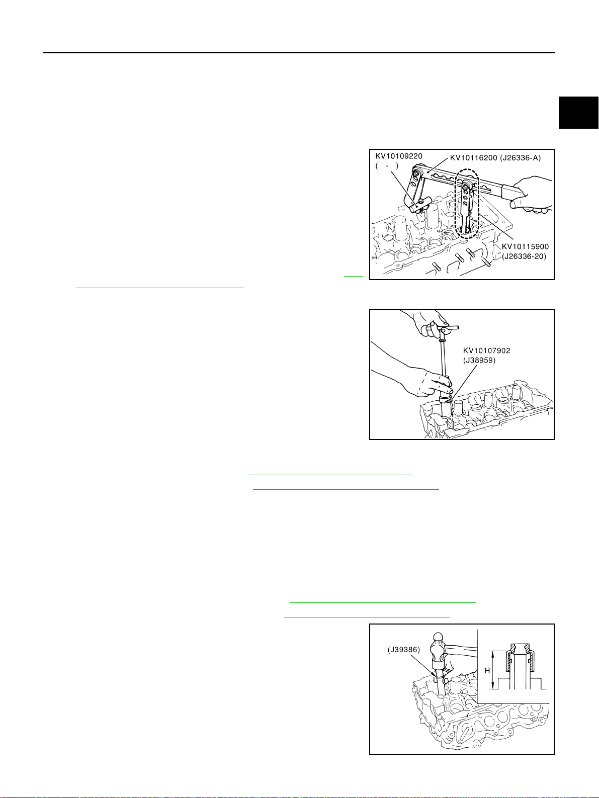
CYLINDER HEAD
EM-103
[VQ35DE]
C
D
E
F
G
H
I
J
K
L
M
A
EM
Revision: 2004 November 2004 FX35/FX45
DISASSEMBLY
1. Remove spark plug with spark plug wrench (commercial service tool).
2. Remove valve lifter.
● Mark position on valve lifter for assembly.
3. Remove valve collet.
● Compress valve spring with valve spring compressor, attach-
ment and adapter (SST). Remove valve collet with magnet
hand.
CAUTION:
When working, take care not to damage valve lifter holes.
4. Remove valve spring retainer and valve spring.
5. Push valve stem to combustion chamber side, and remove
valve.
● Inspect valve guide clearance before removal. Refer to EM-
105, "VALVE GUIDE CLEARANCE" .
● Mark position on valve for assembly.
6. Remove valve oil seals using valve oil seal puller (SST).
7. Remove valve spring seat.
8. If valve seat must be replaced, refer to EM-107, "
VALVE SEAT CONTACT" .
9. If valve guide must be replaced, refer to EM-105, "
VALVE GUIDE CLEARANCE" .
10. Remove spark plug tube, as necessary.
● Using a pair of pliers, pull spark plug tube out of cylinder head.
CAUTION:
● Take care not to damage cylinder head.
● Once removed, a spark plug tube will be deformed and cannot be reused. Do not remove it
unless absolutely necessary.
ASSEMBLY
1. When valve guide is removed, install it. Refer to EM-105, "VALVE GUIDE CLEARANCE" .
2. When valve seat is removed, install it. Refer to EM-107, "
VALVE SEAT CONTACT" .
3. Install valve oil seals.
● Install with valve oil seal drift (SST) to match dimension in
illustration.
4. Install valve spring seat.
10. Cylinder head (right bank) 11. Valve seat 12. Valve (EXH)
13. Valve (INT) 14. Cylinder head (left bank)
PBIC1803E
PBIC0884E
Height “H” (Without valve spring seat installed)
Intake and exhaust : 14.3 - 14.9 mm (0.563 - 0.587 in)
PBIC0802E
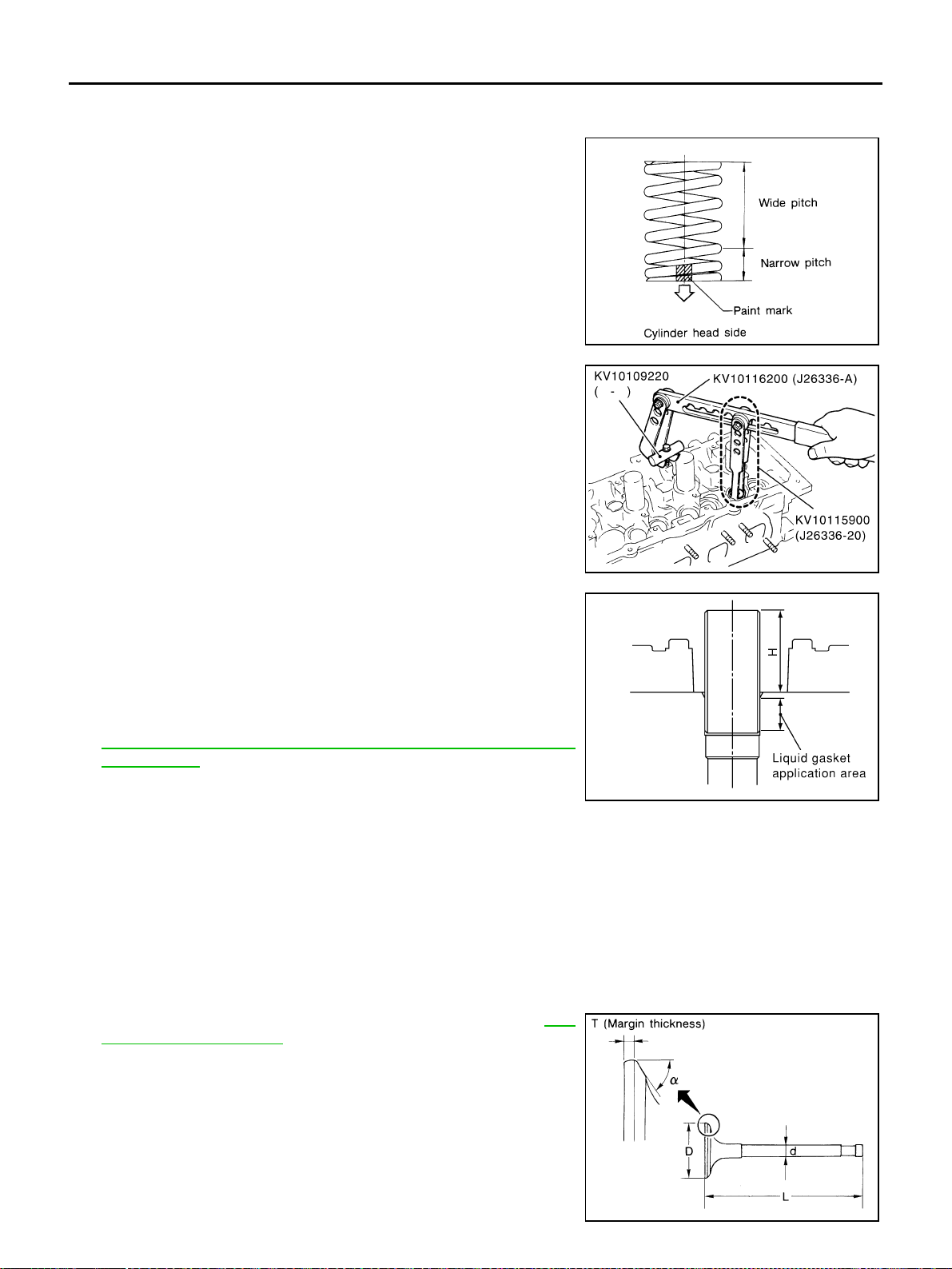
EM-104
[VQ35DE]
CYLINDER HEAD
Revision: 2004 November 2004 FX35/FX45
5. Install the valves.
● Larger diameter valves are for intake side.
6. Install valve spring (uneven pitch type).
● Install smaller pitch end (paint mark) to cylinder head side
(valve spring seat side).
7. Install valve spring retainer.
8. Install valve collet.
● Compress valve spring with valve spring compressor, attach-
ment and adapter (SST). Install valve collet with magnet
hand.
CAUTION:
When working, take care not to damage valve lifter holes.
● Tap valve stem edge lightly with plastic hammer after installa-
tion to check its installed condition.
9. Install valve lifter.
10. Install spark plug tube.
● Press-fit spark plug tube following procedure below.
a. Remove old liquid gasket adhering to cylinder-head mounting
hole.
b. Apply liquid gasket to area within approximately 12 mm (0.47 in)
from edge of spark plug tube press-fit side.
Use Genuine RTV Silicone Sealant or equivalent. Refer to
GI-48, "
RECOMMENDED CHEMICAL PRODUCTS AND
SEALANTS" .
c. Using a drift, press-fit spark plug tube so that its height “H” is as
specified in the figure.
CAUTION:
● When press-fitting, take care not to deform spark plug tube.
● After press-fitting, wipe off liquid gasket protruding onto cylinder-head upper face.
11. Install spark plug.
Inspection After Disassembly ABS004XA
VALVE DIMENSIONS
● Check dimensions of each valve. For dimensions, refer to EM-
150, "Valve Dimensions" .
● If dimensions are out of the standard, replace valve.
SEM085D
PBIC1803E
Standard press-fit height “H”:
: 38.55 - 38.65 mm (1.5177 - 1.5217 in)
KBIA1248E
SEM188A
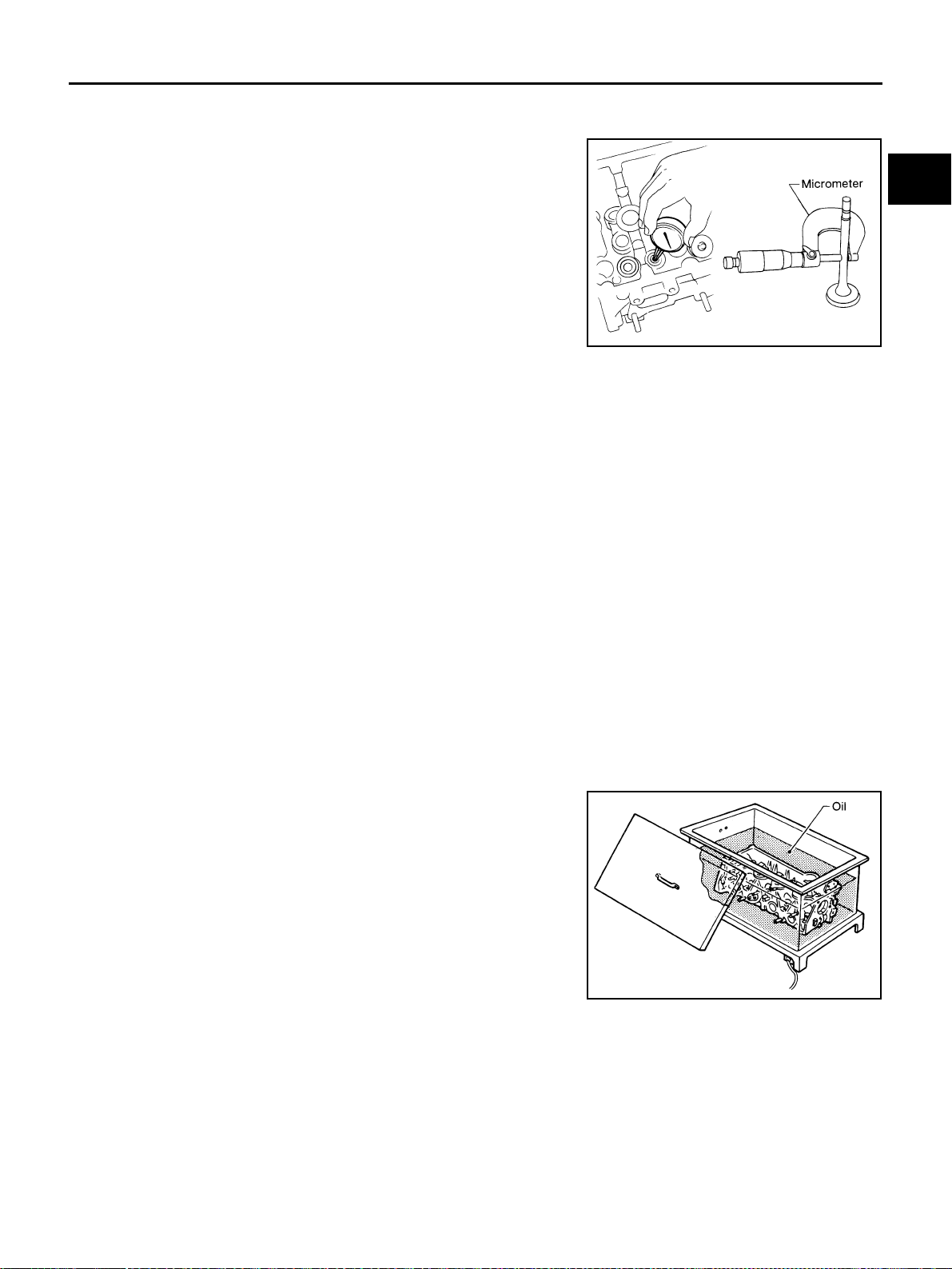
CYLINDER HEAD
EM-105
[VQ35DE]
C
D
E
F
G
H
I
J
K
L
M
A
EM
Revision: 2004 November 2004 FX35/FX45
VALVE GUIDE CLEARANCE
Valve Stem Diameter
Measure inner diameter of valve guide with inside micrometer.
Valve Guide Inner Diameter
Measure inner diameter of valve guide with inside micrometer.
Valve Guide Clearance
● (Valve guide clearance) = (Valve guide inner diameter) – (Valve stem diameter).
● If it exceeds the limit, replace valve guide and / or valve.
VALVE GUIDE REPLACEMENT
When valve guide is removed, replace with oversized (0.2 mm, 0.008 in) valve guide.
1. To remove valve guide, heat cylinder head to 110 to 130°C (230
to 266°F) by soaking in heated oil.
Standard
Intake : 5.965 - 5.980 mm (0.2348 - 0.2354 in)
Exhaust : 5.955 - 5.970 mm (0.2344 - 0.2350 in)
SEM938C
Standard
Intake and
Exhaust
: 6.000 - 6.018 mm (0.2362 - 0.2369 in)
Valve guide clearance:
Standard
Intake : 0.020 - 0.053 mm (0.0008 - 0.0021 in)
Exhaust : 0.030 - 0.063 mm (0.0012 - 0.0025 in)
Limit
Intake : 0.08 mm (0.003 in)
Exhaust : 0.09 mm (0.004 in)
SEM008A
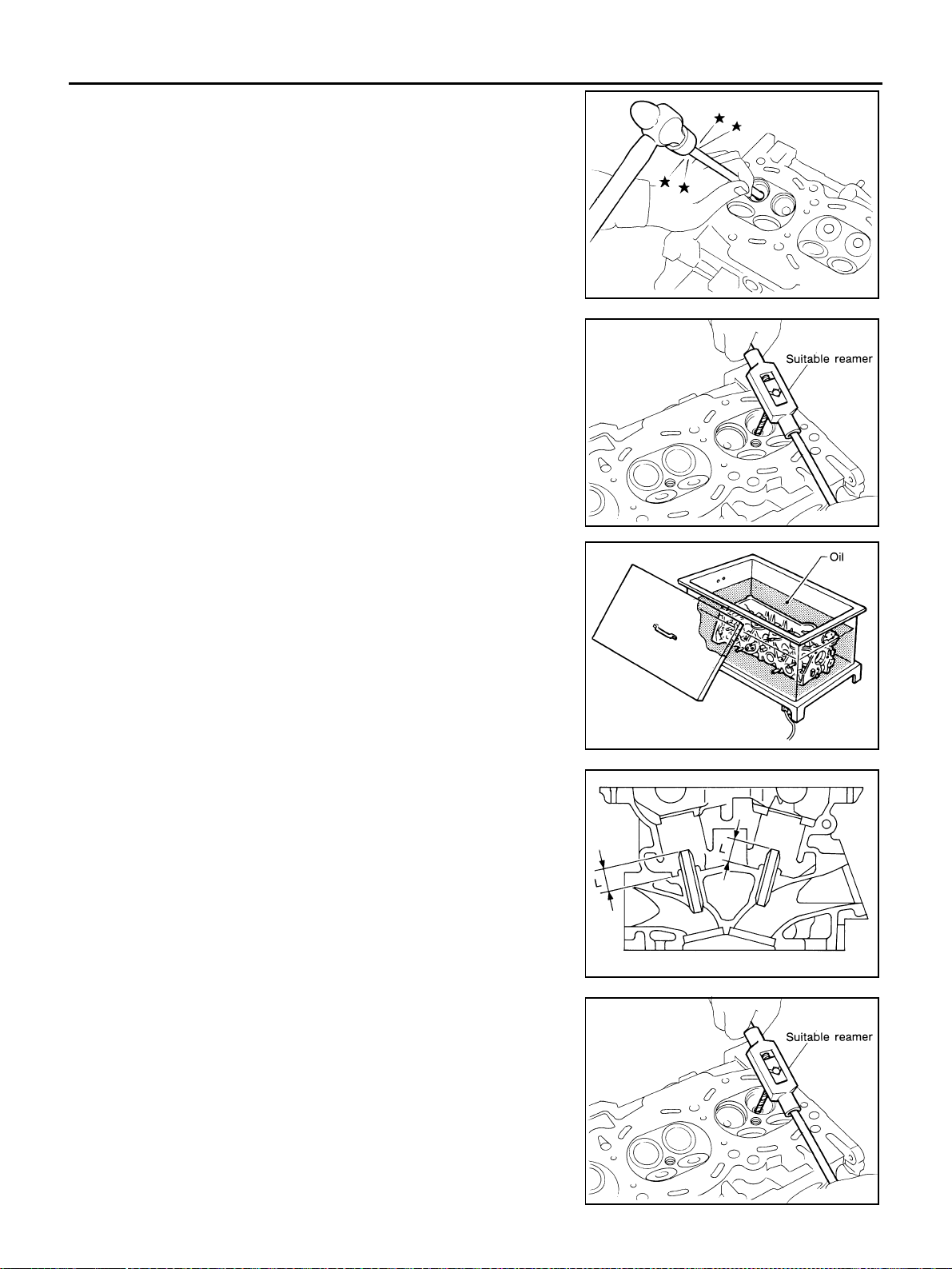
EM-106
[VQ35DE]
CYLINDER HEAD
Revision: 2004 November 2004 FX35/FX45
2. Drive out valve guide with a press [under a 20 kN (2 ton, 2.2 US
ton, 2.0 lmp ton) pressure] or hammer and suitable tool.
CAUTION:
Cylinder head contains heat. When working, wear protec-
tive equipment to avoid getting burned.
3. Using valve guide reamer, ream cylinder head valve guide hole.
4. Heat cylinder head to 110 to 130°C (230 to 266°F) by soaking in
heated oil.
5. Press valve guide from camshaft side to dimensions as in illus-
tration.
CAUTION:
Cylinder head contains heat. When working, wear protec-
tive equipment to avoid getting burned.
6. Using valve guide reamer, apply reamer finish to valve guide.
SEM931C
Valve guide hole diameter (for service parts):
Intake and exhaust
: 10.175 - 10.196 mm (0.4006 - 0.4014 in)
SEM932C
SEM008A
Projection “L”
Intake and exhaust
: 12.6 - 12.8 mm (0.496 - 0.504 in)
SEM950E
Standard:
Intake and exhaust
: 6.000 - 6.018 mm (0.2362 - 0.2369 in)
SEM932C
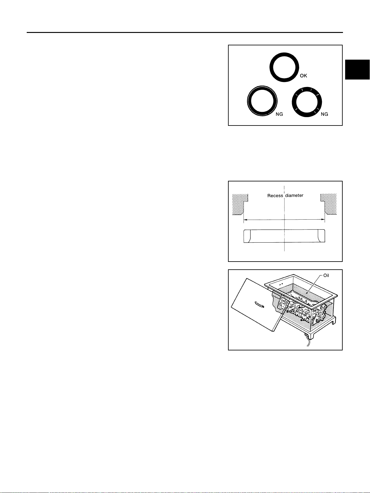
CYLINDER HEAD
EM-107
[VQ35DE]
C
D
E
F
G
H
I
J
K
L
M
A
EM
Revision: 2004 November 2004 FX35/FX45
VALVE SEAT CONTACT
● After confirming that the dimensions of valve guides and valves
are within specifications, perform this procedure.
● Apply prussian blue (or white lead) onto contacting surface of
valve seat to check the condition of the valve contact on the sur-
face.
● Check if the contact area band is continuous all around the cir-
cumference.
● If not, grind to adjust valve fitting and check again. If the contact-
ing surface still has NG conditions even after the re-check,
replace valve seat.
VALVE SEAT REPLACEMENT
When valve seat is removed, replace with oversized (0.5 mm, 0.020 in) valve seat.
1. Bore out old seat until it collapses. Boring should not continue beyond the bottom face of the seat recess
in cylinder head. Set the machine depth stop to ensure this.
CAUTION:
Prevent to scratch cylinder head by excessive boring.
2. Ream cylinder head recess diameter for service valve seat.
● Be sure to ream in circles concentric to the valve guide center.
This will enable valve to fit correctly.
3. Heat cylinder head to 110 to 130°C (230 to 266°F) by soaking in
heated oil.
4. Provide valve seats cooled well with dry ice. Force fit valve seat into cylinder head.
CAUTION:
● Avoid directly touching cold valve seats.
● Cylinder head contains heat. When working, wear protective equipment to avoid getting burned.
SBIA0322E
Oversize [0.5 mm (0.020 in)]
Intake: 38.500 - 38.516 mm (1.5157 - 1.5164 in)
Exhaust: 32.700 - 32.716 mm (1.2874 - 1.2880 in)
SEM795A
SEM008A
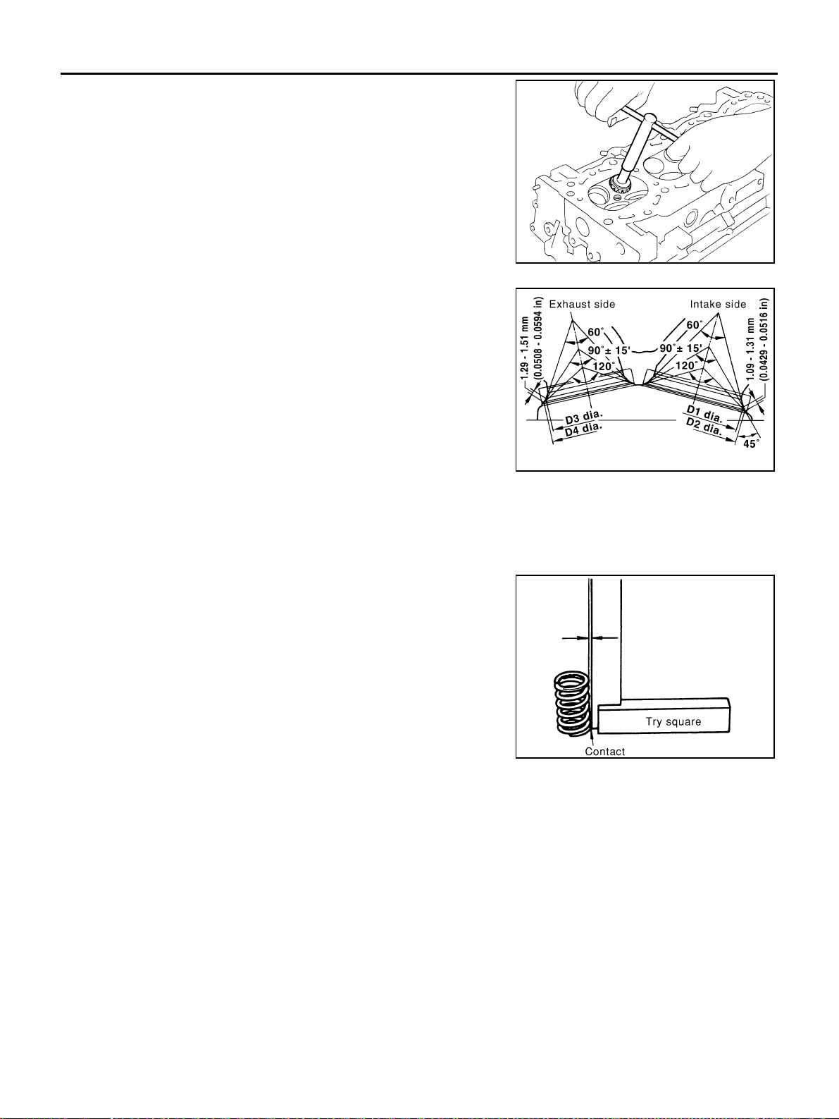
EM-108
[VQ35DE]
CYLINDER HEAD
Revision: 2004 November 2004 FX35/FX45
5. Using valve seat cutter set (commercial service tool) or valve
seat grinder, finish seat to the specified dimensions.
CAUTION:
When using valve seat cutter, firmly grip the cutter handle
with both hands. Then, press on the contacting surface all
around the circumference to cut in a single drive. Improper
pressure on with cutter or cutting many different times may
result in stage valve seat.
Grind to obtain the dimensions indicated.
*1 : Diameter made by intersection point of conic angles 60°
and 90°
*2 : Diameter made by intersection point of conic angles
89.5° and 120°
6. Using compound, grind to adjust valve fitting.
7. Check for normal contact again.
VALVE SPRING SQUARENESS
● Set try square along the side of valve spring and rotate spring.
Measure the maximum clearance between the top face of spring
and try square.
● If it exceeds the limit, replace valve spring.
SEM934C
Standard:
D1 dia.: 35 mm (1.38 in)*
1
D2 dia.: 36.6 - 36.8 mm (1.441 - 1.449 in)*
2
D3 dia.: 28.7 mm (1.130 in)*
1
D4 dia.: 30.6 - 30.8 mm (1.205 - 1.213 in)*
2
SBIA0531E
Limit : Less than 2.1 mm (0.083 in)
PBIC0080E
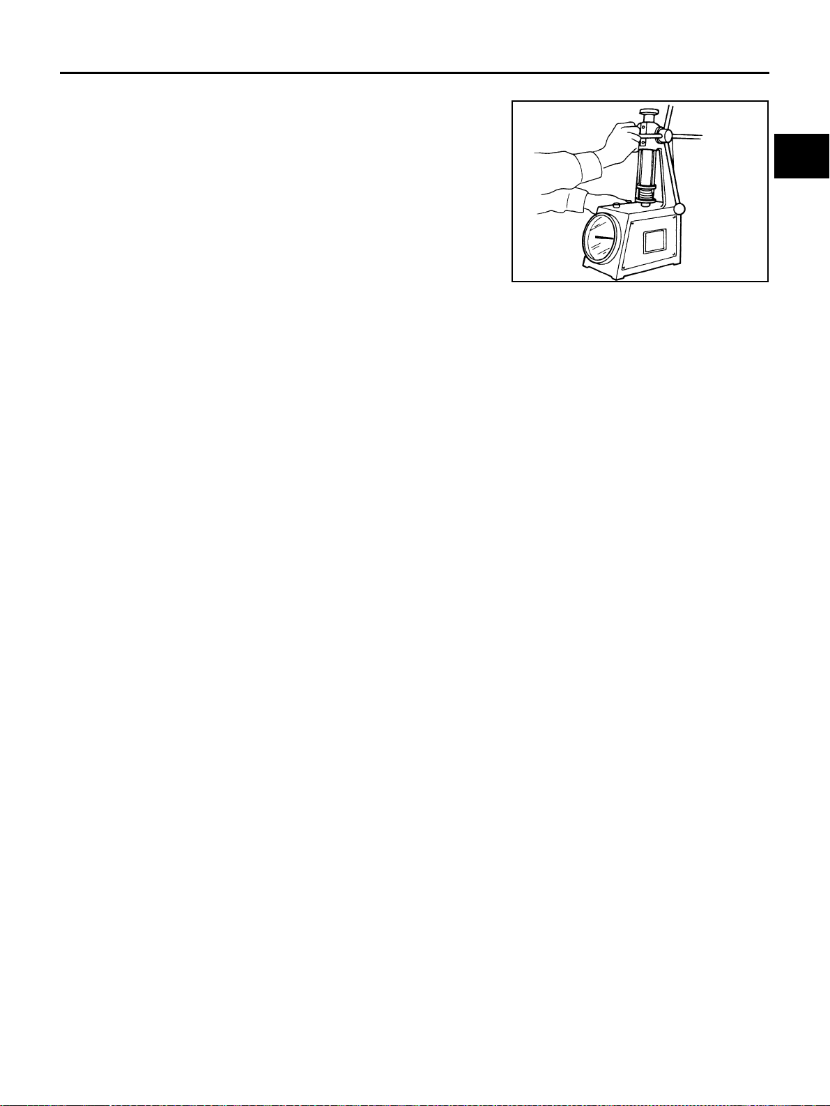
CYLINDER HEAD
EM-109
[VQ35DE]
C
D
E
F
G
H
I
J
K
L
M
A
EM
Revision: 2004 November 2004 FX35/FX45
VALVE SPRING DIMENSIONS AND VALVE SPRING PRESSURE LOAD
● Check the valve spring pressure at specified spring height.
● If the installation load or load with valve open is out of the standard, replace valve spring.
Standard:
Intake and exhaust
Free height
: 47.07 mm (1.8531 in)
Installation height
: 37.0 mm (1.457 in)
Installation load
: 166 - 188 N (16.9 - 19.2 kg, 37.3 - 42.3 lb)
Height during valve open
: 27.2 mm (1.0709 in)
Load with valve open
: 373 - 421 N (38.0 - 42.9 kg, 83.9 - 94.6 lb)
SEM113
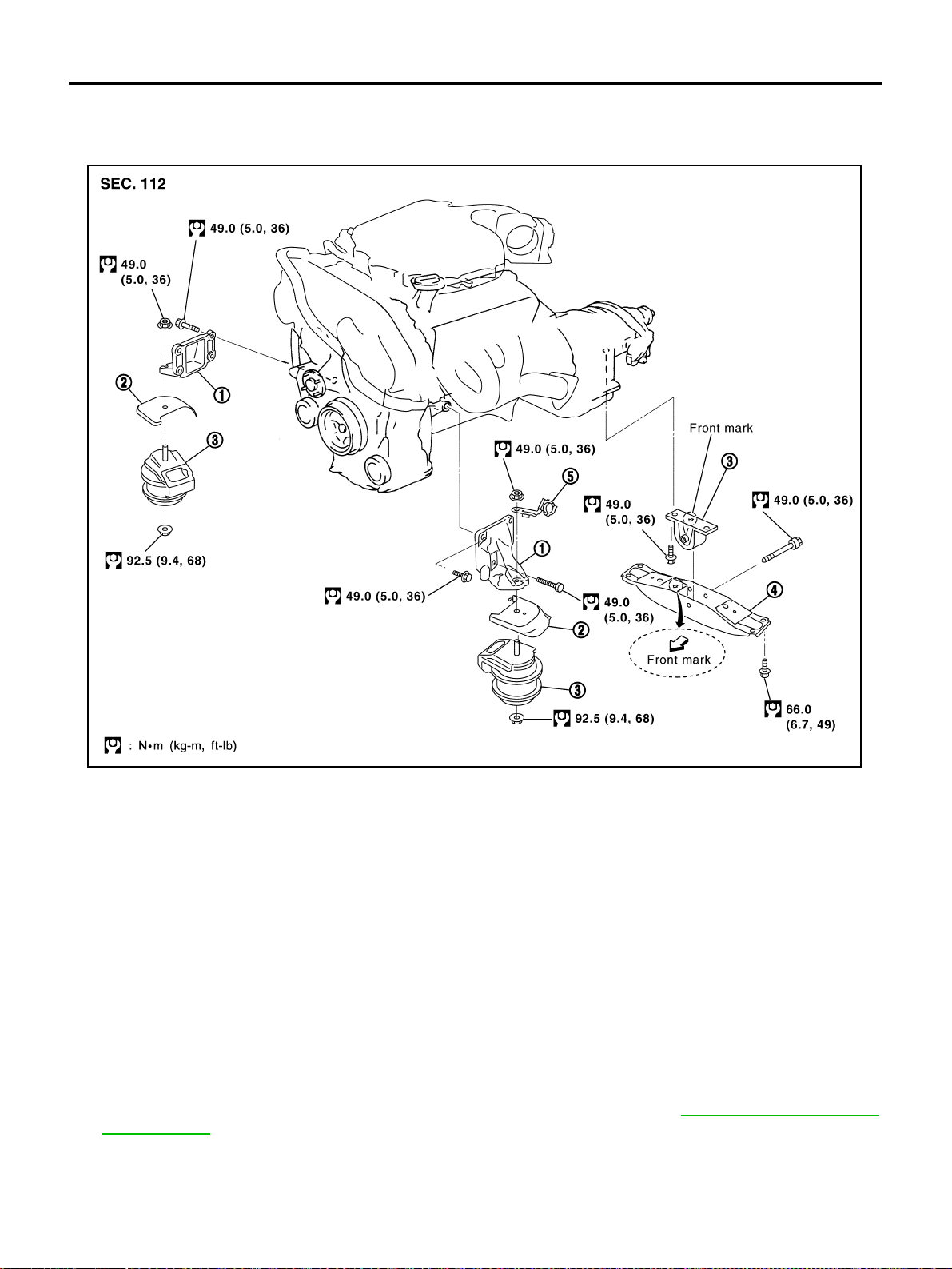
EM-110
[VQ35DE]
ENGINE ASSEMBLY
Revision: 2004 November 2004 FX35/FX45
ENGINE ASSEMBLY PFP:10001
Removal and Installation ABS008GN
2WD MODEL
WARNING:
● Situate vehicle on a flat and solid surface.
● Place chocks at front and back of rear wheels.
● For engines not equipped with engine slingers, attach proper slingers and bolts described in
PARTS CATALOG.
CAUTION:
● Always be careful to work safely, avoid forceful or uninstructed operations.
● Do not start working until exhaust system and engine coolant are cool enough.
● If items or work required are not covered by the engine section, refer to the applicable sections.
● Always use the support point specified for lifting.
● Use either 2-point lift type or separate type lift as best you can. If board-on type is used for
unavoidable reasons, support at rear axle jacking point with transmission jack or similar tool
before starting work, in preparation for the backward shift of center of gravity.
● For supporting points for lifting and jacking point at rear axle, refer to GI-42, "Garage Jack and
Safety Stand" .
1. Engine mounting bracket 2. Heat insulator 3. Engine mounting insulator
4. Rear member 5. Harness bracket
SBIA0476E
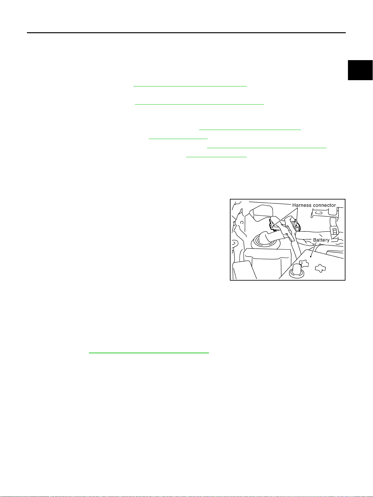
ENGINE ASSEMBLY
EM-111
[VQ35DE]
C
D
E
F
G
H
I
J
K
L
M
A
EM
Revision: 2004 November 2004 FX35/FX45
REMOVAL
Outline
At first, remove engine and transmission assembly with suspension member downward. Then separate
engine from transmission.
Preparation
1. Release fuel pressure. Refer to EC-51, "FUEL PRESSURE RELEASE" .
2. Disconnect both battery terminals.
3. Remove engine cover (Refer to EM-19, "
INTAKE MANIFOLD COLLECTOR" ), battery cover and LH/RH
sides front tire.
4. Remove front and rear engine undercover and front cross bar with power tool.
5. Drain engine coolant from radiator drain plug. Refer to CO-11, "
Changing Engine Coolant" .
6. Remove cowl top cover RH. Refer to EI-24, "
COWL TOP" .
7. Remove air duct and air cleaner case assembly. Refer to EM-17, "
AIR CLEANER AND AIR DUCT" .
8. Remove radiator upper and lower hoses. Refer to CO-14, "
RADIATOR" .
Engine Room
1. Disconnect heater hose from vehicle-side, and fit a plug onto hose end to prevent engine coolant leak.
2. Disconnect grounding wire (between vehicle to left bank cylinder head).
3. Disconnect battery positive cable at vehicle side and temporarily fasten it on engine.
4. Disconnect engine room harness connectors shown in the fig-
ure.
5. Disconnect A/C piping from A/C compressor, and temporarily fasten it on vehicle with a rope.
6. Disconnect two body ground cables.
7. Disconnect brake booster vacuum hose.
8. Disconnect fuel feed hose and EVAP hose.
CAUTION:
Fit plugs onto disconnected hoses to prevent fuel leak.
9. Remove power steering oil pump reservoir tank and piping from vehicle, and temporarily secure them on
engine. Refer to PS-31, "
POWER STEERING OIL PUMP" .
CAUTION:
When temporarily securing, keep them upright to avoid a fluid leak.
Passenger Room Side
1. Follow procedure below to disconnect engine room harness connectors at passenger room side, and tem-
porarily secure them on engine.
SBIA0472E
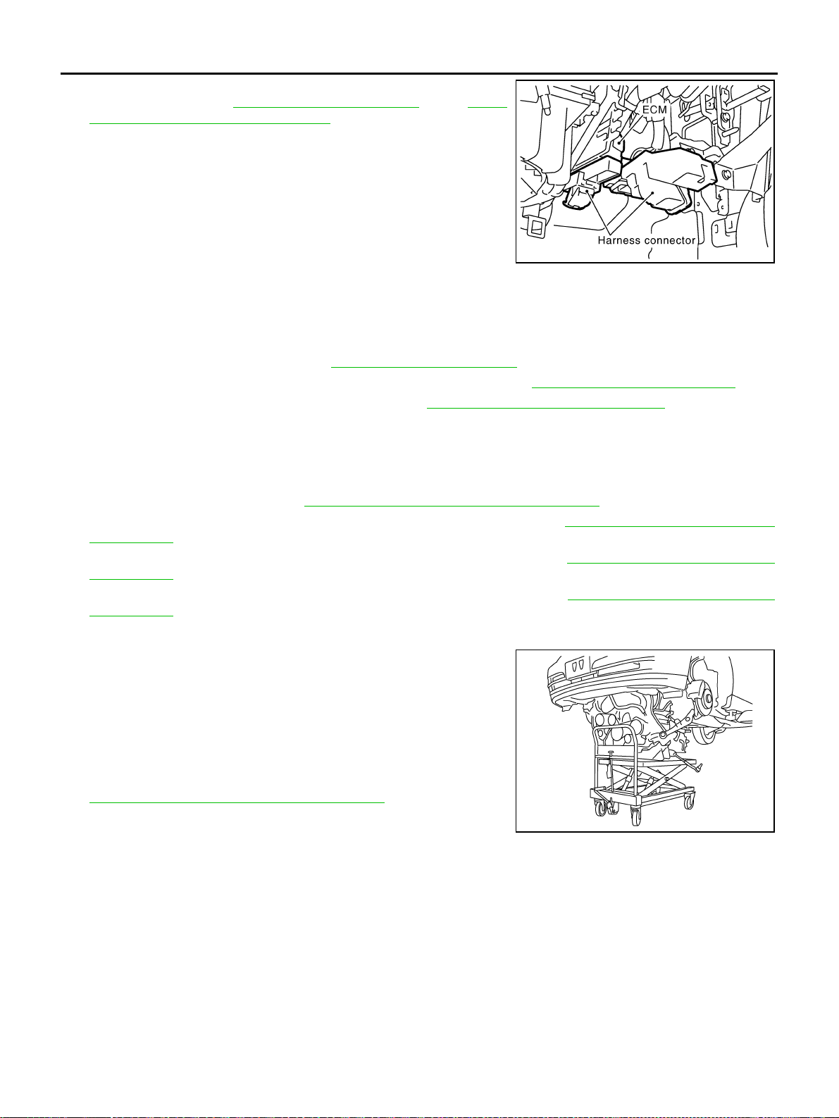
EM-112
[VQ35DE]
ENGINE ASSEMBLY
Revision: 2004 November 2004 FX35/FX45
a. Remove passenger-side kicking plate, dash side finisher, and
glove box. Refer to EI-37, "
BODY SIDE TRIM" and IP-10,
"INSTRUMENT PANEL ASSEMBLY" .
b. Disconnect engine room harness connectors at unit sides ECM
and other.
c. Disengage intermediate fixing point. Pull out engine room har-
nesses to engine room side, and temporarily secure them on
engine.
CAUTION:
● When pulling out harnesses, take care not to damage
harnesses and connectors.
● After temporarily securing, cover connectors with vinyl or similar material to protect against for-
eign material adhesion.
Vehicle Underbody
1. Remove A/T fluid cooler hoses and power steering oil pump oil cooler hoses.
2. Remove exhaust front tube. Refer to EX-3, "EXHAUST SYSTEM" .
3. Disconnect steering lower joint, and release steering shaft. Refer to PS-12, "
STEERING COLUMN" .
4. Separate transmission and propeller shaft. Refer to PR-6, "
REAR PROPELLER SHAFT" .
5. Disengage shift control linkage at selector lever side. Then, temporarily secure it on transmission, so that
it does not sag.
6. Remove rear plate cover from upper oil pan. Then, remove bolts fixing drive plate to torque converter.
7. Remove bolts fixing transmission to lower rear side of upper oil pan.
8. Remove front stabilizer. Refer to FSU-6, "
FRONT SUSPENSION ASSEMBLY" .
9. Remove LH and RH sides tie-rod ends from steering knuckle. Refer to FSU-6, "
FRONT SUSPENSION
ASSEMBLY" .
10. Remove lower ends of LH and RH sides struts from lower arms. Refer to FSU-6, "
FRONT SUSPENSION
ASSEMBLY" .
11. Remove LH and RH sides lower arms from suspension member. Refer to FSU-6, "
FRONT SUSPENSION
ASSEMBLY" .
Removal Work
1. Use a manual lift table caddy (commercial service tool) or equiv-
alently rigid tool such as a transmission jack. Securely support
bottom of suspension member and transmission.
CAUTION:
Put a piece of wood or something similar as the supporting
surface, secure a completely stable condition.
2. Remove rear member mounting bolt.
3. Remove suspension member mounting bolt and nut. Refer to
FSU-6, "
FRONT SUSPENSION ASSEMBLY" .
4. Carefully lower jack to remove engine, transmission, and sus-
pension member assembly. When performing work, observe the
following:
CAUTION:
● Confirm there is no interference with vehicle.
● Make sure all connection points have been disconnected.
● Keep in mind the center of vehicle gravity changes. If necessary, use jack(s) to support vehicle
at rear jacking point(s) to prevent it from falling it off lift.
SBIA0473E
PBIC0804E
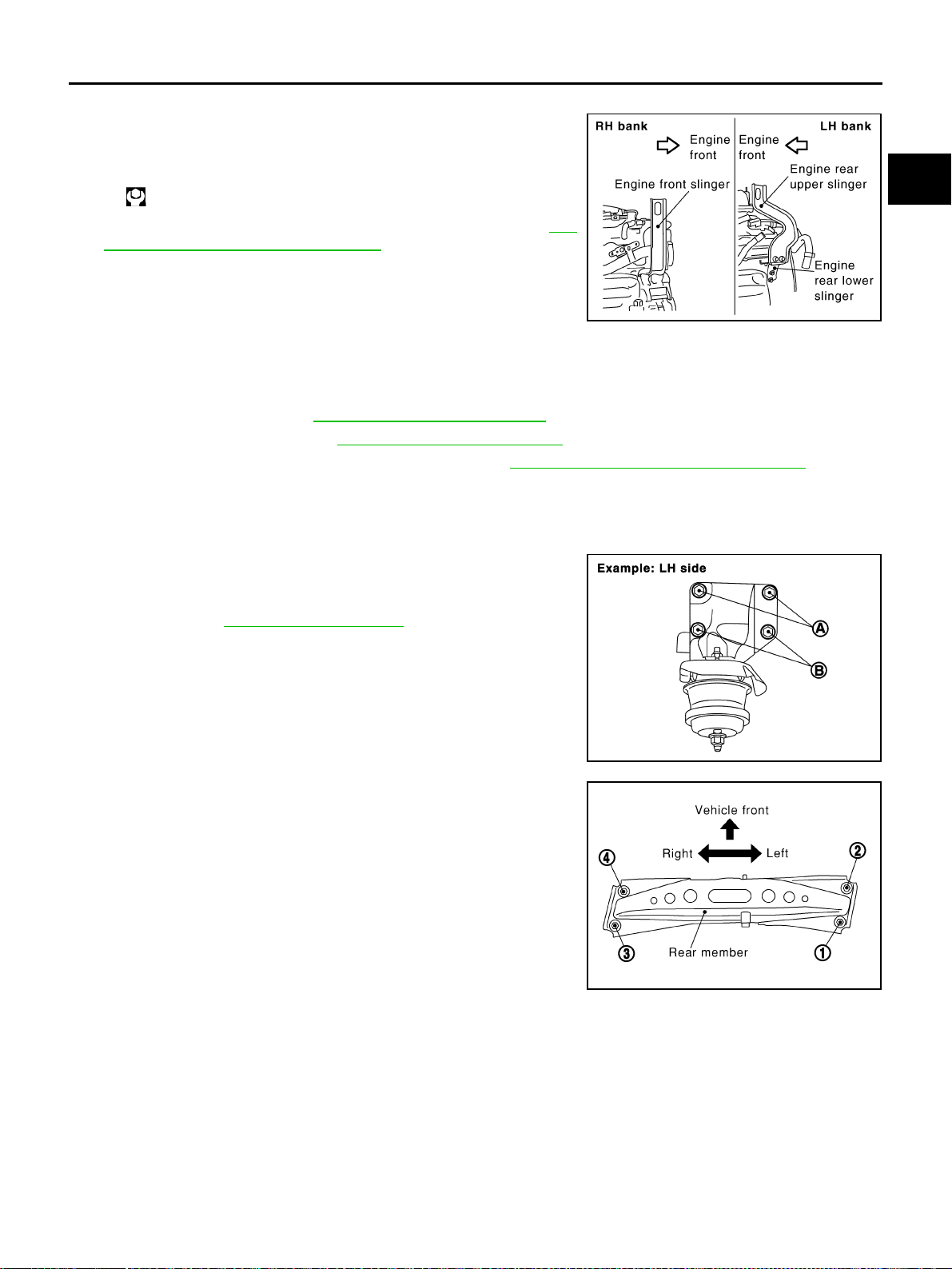
ENGINE ASSEMBLY
EM-113
[VQ35DE]
C
D
E
F
G
H
I
J
K
L
M
A
EM
Revision: 2004 November 2004 FX35/FX45
Separation Work
1. Install engine slingers into front of right bank cylinder head and
rear of left bank cylinder head.
2. Remove power steering oil pump from engine side. Refer to PS-
31, "POWER STEERING OIL PUMP" .
3. Remove engine mounting insulator under side nut with power
tool.
4. Lift with hoist and separate engine and transmission assembly
from suspension member.
CAUTION:
● Before and during this lifting, always check if any harnesses are left connected.
● Avoid damage to and oil/grease smearing or spills onto engine mounting insulator.
5. Remove alternator. Refer to SC-23, "
CHARGING SYSTEM" .
6. Remove starter motor. Refer to SC-10, "
STARTING SYSTEM" .
7. Separate engine from transmission assembly. Refer to AT-266, "
TRANSMISSION ASSEMBLY" .
8. Remove engine mounting insulator and bracket with power tool.
INSTALLATION
Note to the following, and install in the reverse order of removal.
● For a location with a positioning pin, insert it securely into hole of
mating part.
● For a part with a specified installation orientation, refer to com-
ponent figure in EM-110, "
2WD MODEL" .
● When installing engine mounting bracket on cylinder block,
tighten two upper bolts (shown as A in figure) first. Then tighten
two lower bolts (shown as B in figure). (LH and RH sides)
● Tighten rear member mounting bolts in numerical order shown
in figure.
INSPECTION AFTER INSTALLATION
● Before starting engine, check the levels of engine coolant, engine oil and working fluid. If less than
required quantity, fill to the specified level.
● Use procedure below to check for fuel leakage.
– Turn ignition switch ON (with engine stopped). With fuel pressure applied to fuel piping, check for fuel
leakage at connection points.
– Start engine. With engine speed increased, check again for fuel leakage at connection points.
● Run engine to check for unusual noise and vibration.
● Warm up engine thoroughly to make sure there is no leakage of engine coolant, engine oil, working fluid,
fuel and exhaust gas.
Slinger bolts:
: 28.0 N·m (2.9 kg-m, 21 ft-lb)
SBIA0474E
PBIC1134E
KBIA1019E

EM-114
[VQ35DE]
ENGINE ASSEMBLY
Revision: 2004 November 2004 FX35/FX45
● Bleed air from passages in pipes and tubes of applicable lines, such as in cooling system.
● After cooling down engine, again check amounts of engine coolant, engine oil and working fluid. Refill to
specified level, if necessary.
● Summary of the inspection items:
Item Before starting engine Engine running After engine stopped
Engine coolant Level Leakage Level
Engine oil Level Leakage Level
Working fluid Level Leakage Level
Fuel — Leakage —
Exhaust gas — Leakage —
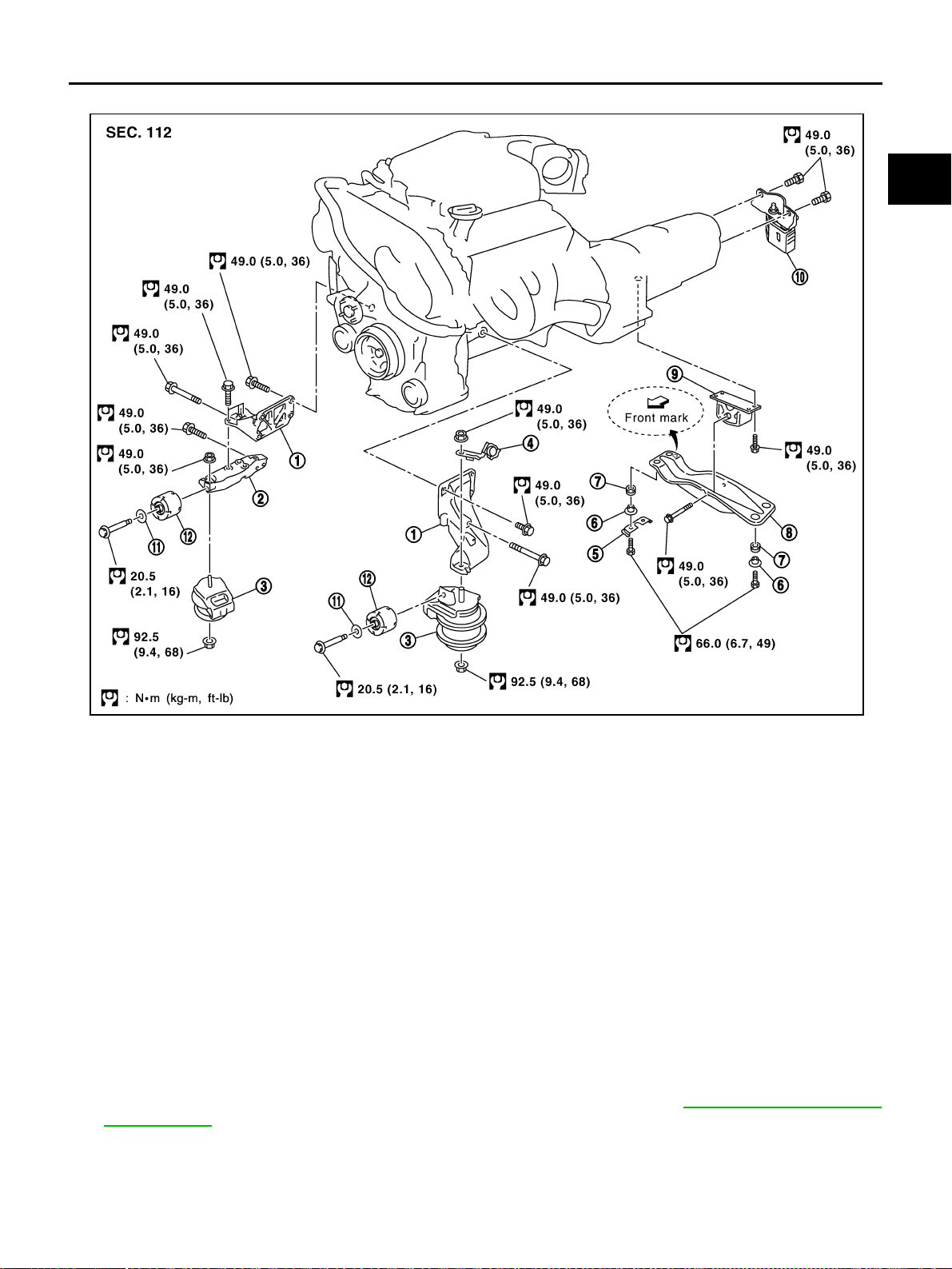
ENGINE ASSEMBLY
EM-115
[VQ35DE]
C
D
E
F
G
H
I
J
K
L
M
A
EM
Revision: 2004 November 2004 FX35/FX45
AWD MODEL
WARNING:
● Situate vehicle on a flat and solid surface.
● Place chocks at front and back of rear wheels.
● For engines not equipped with engine slingers, attach proper slingers and bolts described in
PARTS CATALOG.
CAUTION:
● Always be careful to work safely, avoid forceful or uninstructed operations.
● Do not start working until exhaust system and engine coolant are cool enough.
● If items or work required are not covered by the engine section, refer to the applicable sections.
● Always use the support point specified for lifting.
● Use either 2-point lift type or separate type lift as best you can. If board-on type is used for
unavoidable reasons, support at rear axle jacking point with transmission jack or similar tool
before starting work, in preparation for the backward shift of center of gravity.
● For supporting points for lifting and jacking point at rear axle, refer to GI-42, "Garage Jack and
Safety Stand" .
REMOVAL
Outline
At first, remove engine and transmission assembly with suspension member downward. Then separate
engine from transmission.
1. Engine mounting bracket 2. Engine mounting bracket (Lower) 3. Engine mounting insulator FR
4. Harness bracket 5. Heat insulator 6. Caller
7. Rubber bush 8. Rear member 9. Engine mounting insulator RR
10. Dynamic damper 11. Washer 12. Dynamic damper
SBIA0475E
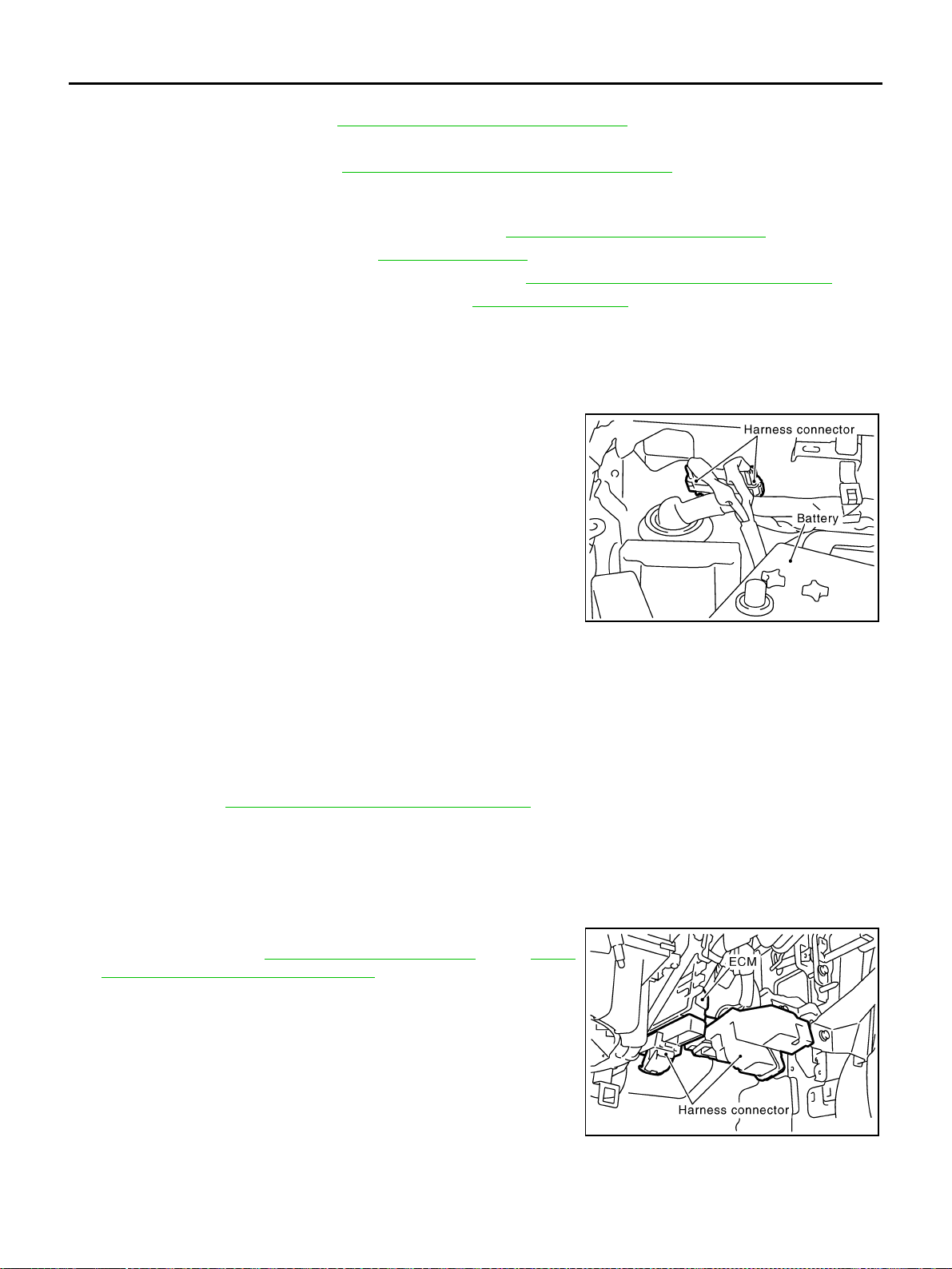
EM-116
[VQ35DE]
ENGINE ASSEMBLY
Revision: 2004 November 2004 FX35/FX45
Preparation
1. Release fuel pressure. Refer to EC-51, "FUEL PRESSURE RELEASE" .
2. Disconnect both battery terminals.
3. Remove engine cover (Refer to EM-19, "
INTAKE MANIFOLD COLLECTOR" ), battery cover and LH/RH
sides front tire.
4. Remove front and rear engine undercover and front cross bar with power tool.
5. Drain engine coolant from radiator drain plug. Refer to CO-11, "
Changing Engine Coolant" .
6. Remove cowl top cover RH. Refer to EI-24, "
COWL TOP" .
7. Remove air duct and air cleaner case assembly. Refer to EM-17, "
AIR CLEANER AND AIR DUCT" .
8. Remove radiator upper and lower hoses. Refer to CO-14, "
RADIATOR" .
Engine Room
1. Disconnect heater hose from vehicle-side, and fit a plug onto hose end to prevent engine coolant leak.
2. Disconnect grounding wire (between vehicle to left bank cylinder head).
3. Disconnect battery positive cable at vehicle side and temporarily fasten it on engine.
4. Disconnect engine room harness connectors shown in the fig-
ure.
5. Disconnect A/C piping from A/C compressor, and temporarily fasten it on vehicle with a rope.
6. Disconnect two body ground cables.
7. Disconnect brake booster vacuum hose.
8. Disconnect fuel feed hose and EVAP hose.
CAUTION:
Fit plugs onto disconnected hoses to prevent fuel leak.
9. Remove power steering oil pump reservoir tank and piping from vehicle, and temporarily secure them on
engine. Refer to PS-31, "
POWER STEERING OIL PUMP" .
CAUTION:
When temporarily securing, keep them upright to avoid a fluid leak.
Passenger Room Side
1. Follow procedure below to disconnect engine room harness connectors at passenger room side, and tem-
porarily secure them on engine.
a. Remove passenger-side kicking plate, dash side finisher, and
glove box. Refer to EI-37, "
BODY SIDE TRIM" and IP-10,
"INSTRUMENT PANEL ASSEMBLY" .
b. Disconnect engine room harness connectors at unit sides ECM
and other.
c. Disengage intermediate fixing point. Pull out engine room har-
nesses to engine room side, and temporarily secure them on
engine.
CAUTION:
● When pulling out harnesses, take care not to damage
harnesses and connectors.
● After temporarily securing, cover connectors with vinyl or similar material to protect against for-
eign material adhesion.
SBIA0472E
SBIA0473E
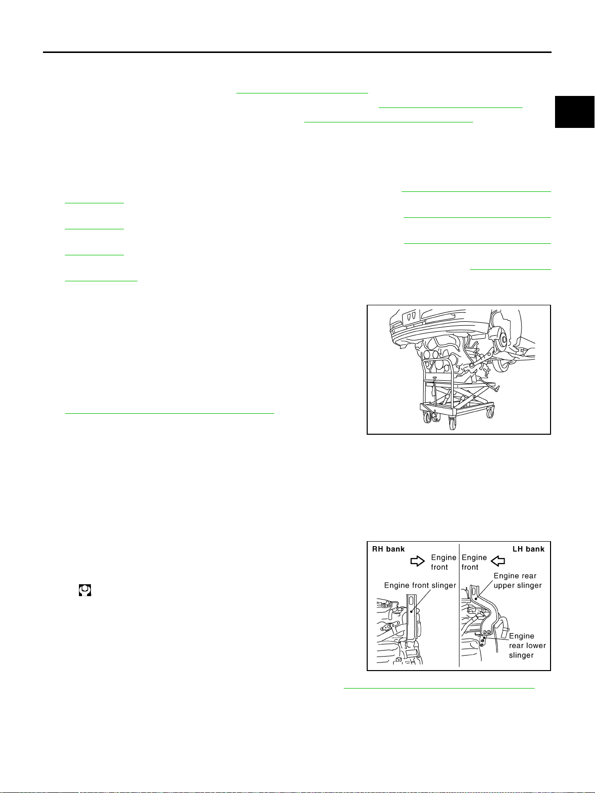
ENGINE ASSEMBLY
EM-117
[VQ35DE]
C
D
E
F
G
H
I
J
K
L
M
A
EM
Revision: 2004 November 2004 FX35/FX45
Vehicle Underbody
1. Remove A/T fluid cooler hoses and power steering oil pump oil cooler hoses.
2. Remove exhaust front tube. Refer to EX-3, "
EXHAUST SYSTEM" .
3. Disconnect steering lower joint, and release steering shaft. Refer to PS-12, "
STEERING COLUMN" .
4. Separate transmission and propeller shaft. Refer to PR-6, "
REAR PROPELLER SHAFT" .
5. Disengage shift control linkage at selector lever side. Then, temporarily secure it on transmission, so that
it does not sag.
6. Remove rear plate cover from upper oil pan. Then, remove bolts fixing drive plate to torque converter.
7. Remove bolts fixing transmission to lower rear side of upper oil pan.
8. Remove LH and RH sides tie-rod ends from steering knuckle. Refer to FSU-6, "
FRONT SUSPENSION
ASSEMBLY" .
9. Remove lower ends of LH and RH sides struts from lower arms. Refer to FSU-6, "
FRONT SUSPENSION
ASSEMBLY" .
10. Remove LH and RH sides lower arms from suspension member. Refer to FSU-6, "
FRONT SUSPENSION
ASSEMBLY" .
11. Remove LH and RH sides front drive shafts from LH and RH sides knuckles. Refer to FAX-12, "FRONT
DRIVE SHAFT" .
Removal Work
1. Use a manual lift table caddy (commercial service tool) or equiv-
alently rigid tool such as a transmission jack. Securely support
bottom of suspension member and transmission.
CAUTION:
Put a piece of wood or something similar as the supporting
surface, secure a completely stable condition.
2. Remove rear member mounting bolt.
3. Remove suspension member mounting bolt and nut. Refer to
FSU-6, "
FRONT SUSPENSION ASSEMBLY" .
4. Carefully lower jack to remove engine, transmission, and sus-
pension member assembly. When performing work, observe the
following:
CAUTION:
● Confirm there is no interference with vehicle.
● Make sure all connection points have been disconnected.
● Keep in mind the center of vehicle gravity changes. If necessary, use jack(s) to support vehicle
at rear jacking point(s) to prevent it from falling it off lift.
Separation Work
1. Install engine slingers into front of RH bank cylinder head and
rear of left bank cylinder head.
2. Remove power steering oil pump from engine side. Refer to PS-31, "
POWER STEERING OIL PUMP" .
3. Remove engine mounting insulator RR under side nut with power tool.
4. Lift with hoist and separate engine and transmission assembly from suspension member.
CAUTION:
● Before and during this lifting, always check if any harnesses are left connected.
● Avoid damage to and oil/grease smearing or spills onto engine mounting insulator.
PBIC0804E
Slinger bolts:
: 28.0 N·m (2.9 kg-m, 21 ft-lb)
SBIA0474E
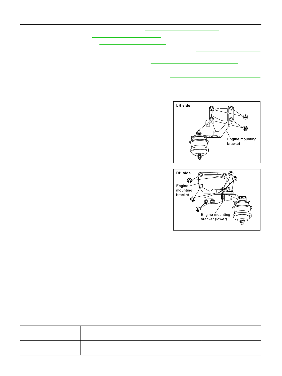
EM-118
[VQ35DE]
ENGINE ASSEMBLY
Revision: 2004 November 2004 FX35/FX45
5. Remove front drive shaft LH and RH sides. Refer to FAX-12, "FRONT DRIVE SHAFT" .
6. Remove alternator. Refer to SC-23, "
CHARGING SYSTEM" .
7. Remove starter motor. Refer to SC-10, "
STARTING SYSTEM" .
8. Remove front propeller shaft from front final drive assembly side. Refer to PR-4, "
FRONT PROPELLER
SHAFT" .
9. Separate engine from transmission assembly. Refer to AT-266, "
TRANSMISSION ASSEMBLY" .
10. Remove engine mounting insulator FR and engine mounting bracket with power tool.
11. Remove front final drive assembly from oil pan (upper). Refer to FFD-10, "
FRONT FINAL DRIVE ASSEM-
BLY" .
INSTALLATION
Note to the following, and install in the reverse order of removal.
● For a location with a positioning pin, insert it securely into hole of
mating part.
● For a part with a specified installation orientation, refer to com-
ponent figure in EM-115, "
AWD MODEL" .
● When installing engine mounting bracket on cylinder block,
tighten two upper bolts (shown as A in figure) first. Then tighten
two lower bolts (shown as B in figure). (LH and RH sides)
● Install engine mounting bracket (lower) paying attention to the
following.
– a. Temporarily tighten mounting bolts (shown as C, D and E in
figure).
– b. Tighten mounting bolts to the specified torque with following
mounting surfaces touched.
• Engine mounting bracket to engine mounting bracket (lower)
(shown as C and D in figure).
• Front final drive to engine mounting bracket (lower) (shown as E
in figure).
INSPECTION AFTER INSTALLATION
● Before starting engine, check the levels of engine coolant, engine oil and working fluid. If less than
required quantity, fill to the specified level.
● Use procedure below to check for fuel leakage.
– Turn ignition switch ON (with engine stopped). With fuel pressure applied to fuel piping, check for fuel
leakage at connection points.
– Start engine. With engine speed increased, check again for fuel leakage at connection points.
● Run engine to check for unusual noise and vibration.
● Warm up engine thoroughly to make sure there is no leakage of engine coolant, engine oil, working fluid,
fuel and exhaust gas.
● Bleed air from passages in pipes and tubes of applicable lines, such as in cooling system.
● After cooling down engine, again check amounts of engine coolant, engine oil and working fluid. Refill to
specified level, if necessary.
● Summary of the inspection items:
SBIA0477E
SBIA0478E
Item Before starting engine Engine running After engine stopped
Engine coolant Level Leakage Level
Engine oil Level Leakage Level
Working fluid Level Leakage Level

ENGINE ASSEMBLY
EM-119
[VQ35DE]
C
D
E
F
G
H
I
J
K
L
M
A
EM
Revision: 2004 November 2004 FX35/FX45
Fuel — Leakage —
Exhaust gas — Leakage —
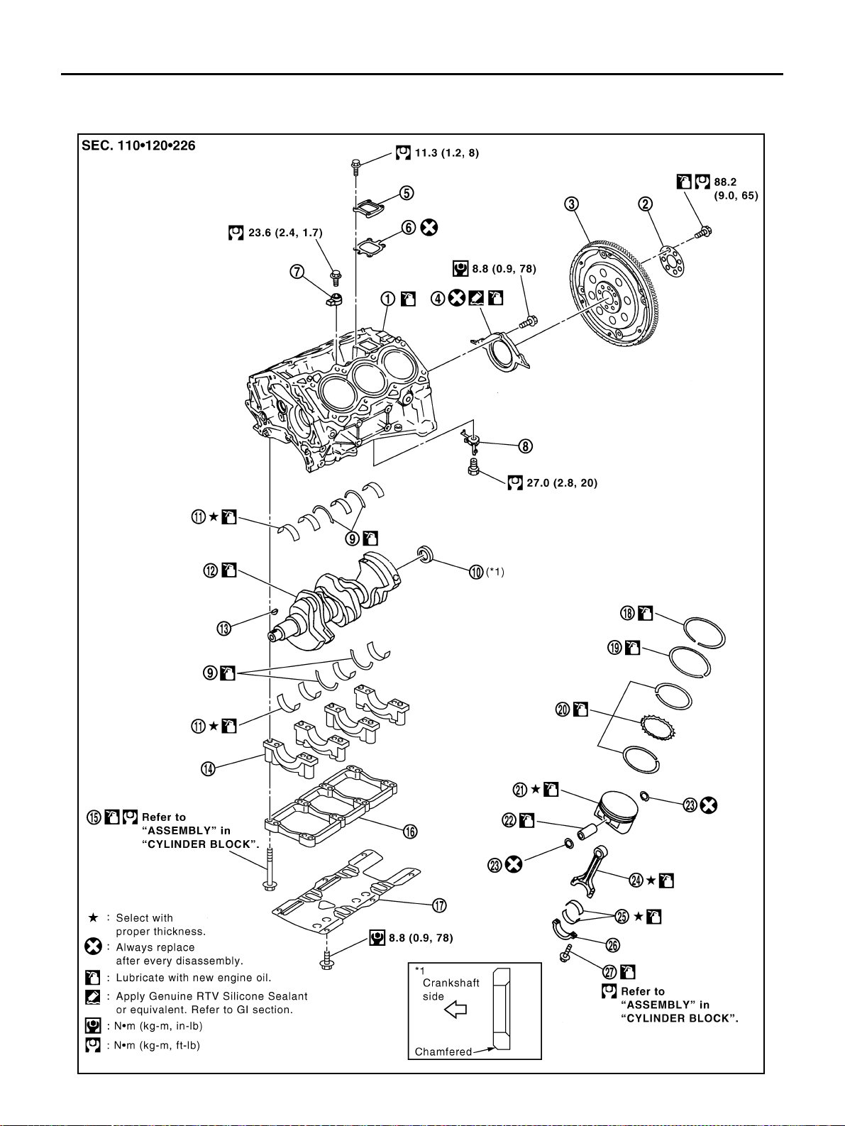
EM-120
[VQ35DE]
CYLINDER BLOCK
Revision: 2004 November 2004 FX35/FX45
CYLINDER BLOCK PFP:11010
Disassembly and Assembly ABS004XH
SBIA0589E
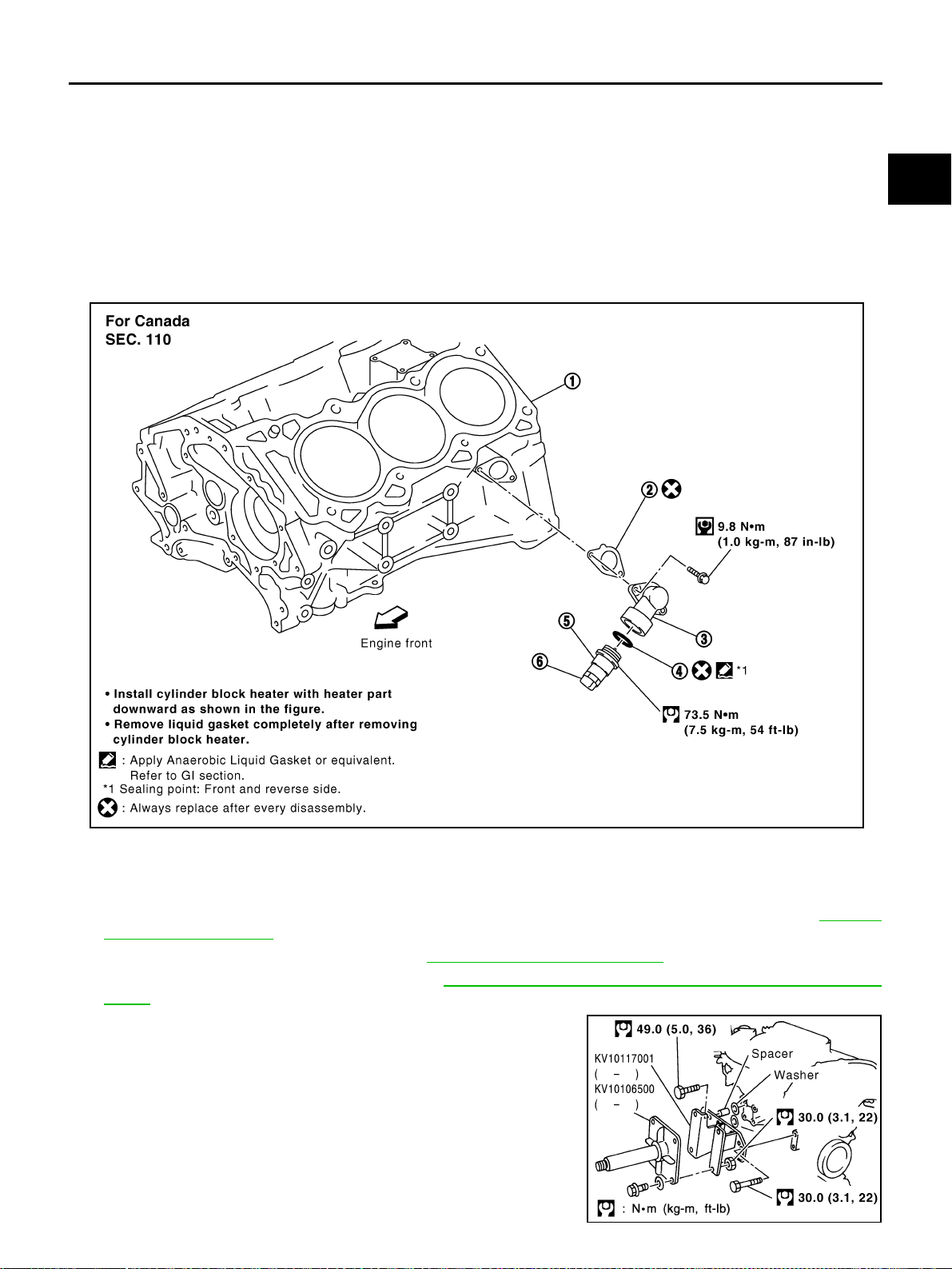
CYLINDER BLOCK
EM-121
[VQ35DE]
C
D
E
F
G
H
I
J
K
L
M
A
EM
Revision: 2004 November 2004 FX35/FX45
DISASSEMBLY
1. Remove engine assembly from vehicle, and separate transmission from engine. Refer to EM-110,
"ENGINE ASSEMBLY" .
2. Remove engine mounting bracket. Refer to EM-110, "
ENGINE ASSEMBLY" .
3. Remove RH side exhaust manifold. Refer to EM-26, "
EXHAUST MANIFOLD AND THREE WAY CATA-
LYST" .
4. Install engine sub-attachment with engine stand shaft (SST) to
right side of cylinder block.
● Use spacer to engine rear side.
1. Cylinder block 2. Reinforcement plate 3. Drive plate
4. Rear oil seal retainer 5. Cover 6. Gasket
7. Knock sensor 8. Oil jet 9. Thrust bearing
10. Pilot converter 11. Main bearing 12. Crankshaft
13. Key 14. Main bearing cap 15. Main bearing cap bolt
16. Main bearing beam 17. Baffle plate (2WD model) 18. Top ring
19. Second ring 20. Oil ring 21. Piston
22. Piston pin 23. Snap ring 24. Connecting rod
25. Connecting rod bearing 26. Connecting rod bearing cap 27. Connecting rod bolt
1. Cylinder block 2. Gasket 3. Water connector
4. Gasket 5. Cylinder block heater 6. Connector protector cap
PBIC2614E
SBIA0503E
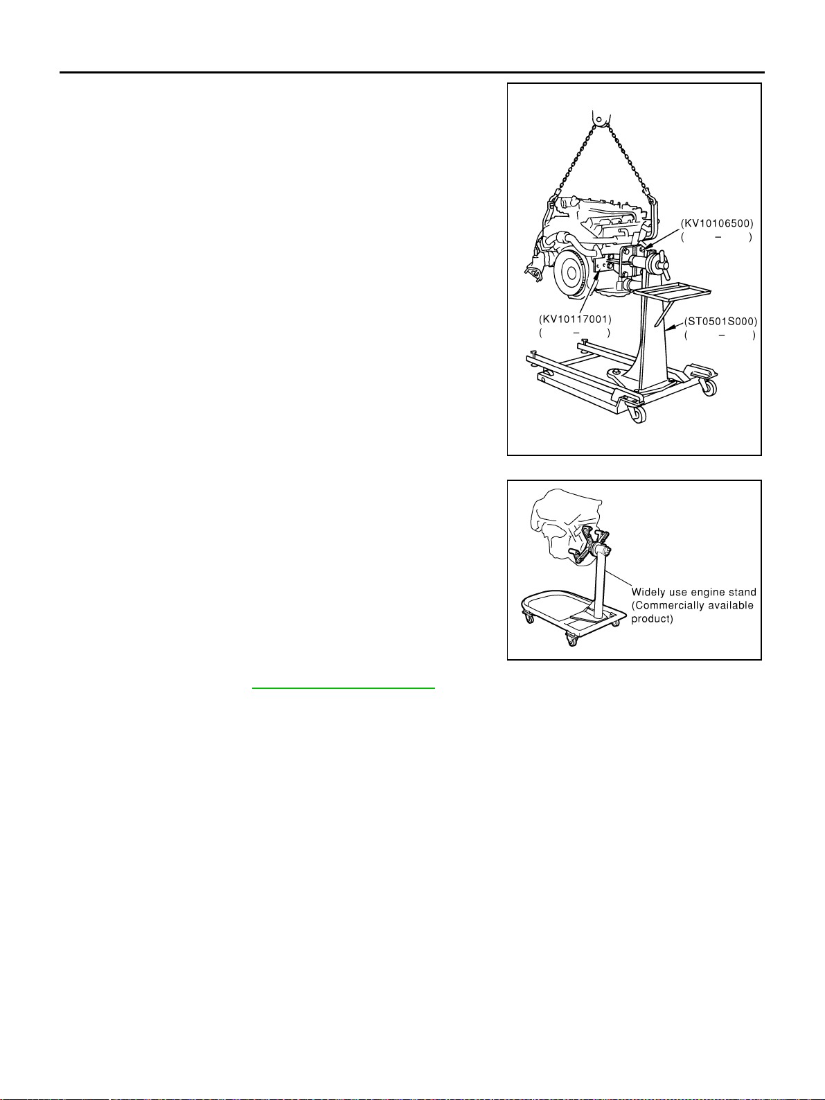
EM-122
[VQ35DE]
CYLINDER BLOCK
Revision: 2004 November 2004 FX35/FX45
5. Lift engine, and mount it onto engine stand (SST).
● A commercial engine stand can be used.
CAUTION:
Use an engine stand that has a load capacity [approxi-
mately 220 kg (441 lb) or more] large enough for support-
ing the engine weight.
NOTE:
This example is an engine stand for holding at transmission
mounting side with drive plate removed.
6. Drain engine oil. Refer to LU-9, "
Changing Engine Oil" .
PBIC0805E
PBIC0085E
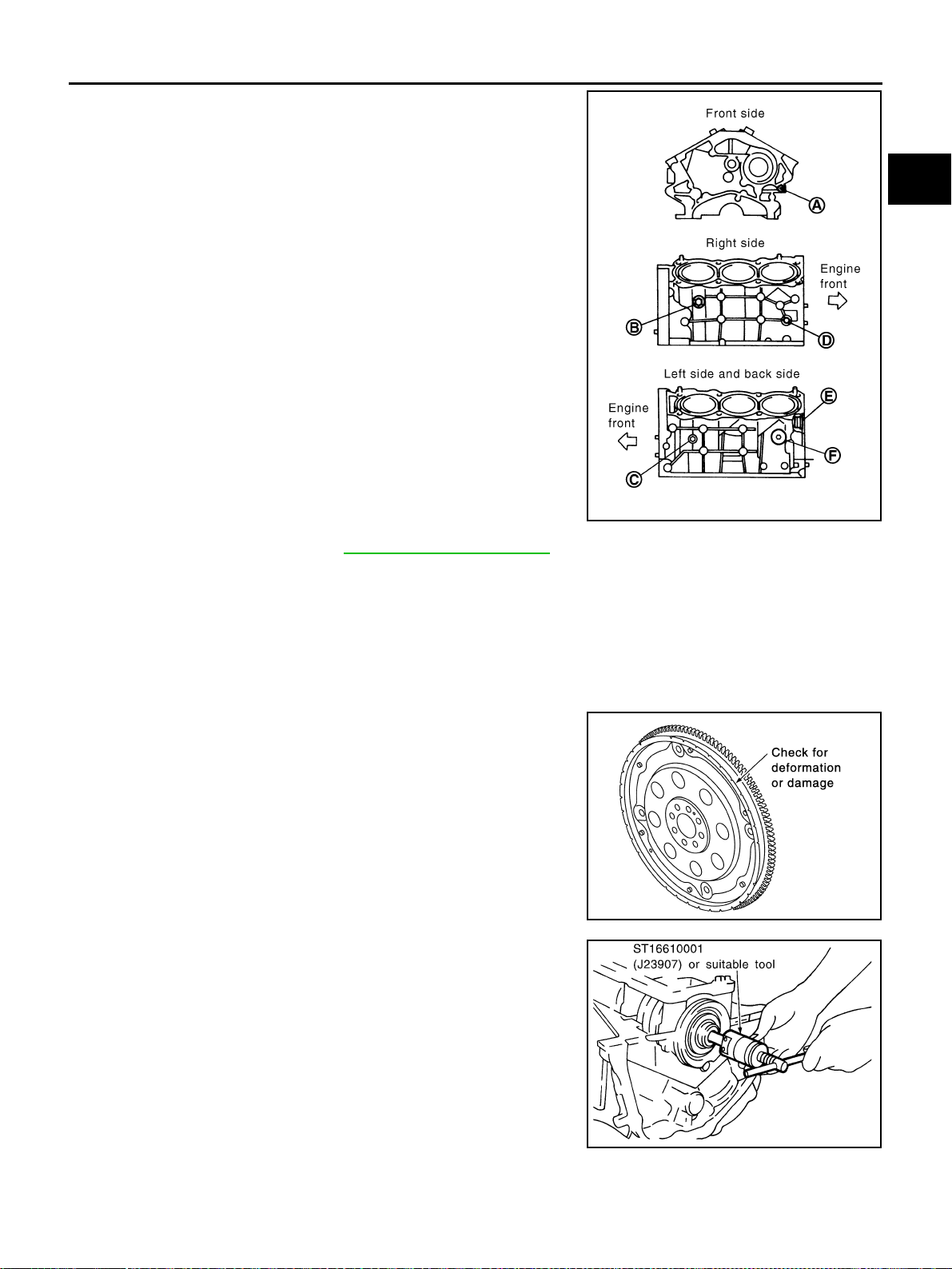
CYLINDER BLOCK
EM-123
[VQ35DE]
C
D
E
F
G
H
I
J
K
L
M
A
EM
Revision: 2004 November 2004 FX35/FX45
7. Drain engine coolant by removing water drain plugs from cylin-
der block both sides at “B” and “C” and cylinder block front side
at “A” as shown in the figure.
8. Remove cylinder head. Refer to EM-98, "
CYLINDER HEAD" .
9. Remove knock sensor.
CAUTION:
Carefully handle sensor avoiding shocks.
10. Remove drive plate with power tool. Fix crankshaft with a ring gear stopper [SST: KV1011770 (J-44716)],
and remove mounting bolts.
● Loosen mounting bolts in diagonal order.
CAUTION:
● Do not disassemble drive plate.
● Never place drive plate with signal plate facing down.
● When handling signal plate, take care not to damage or
scratch it.
● Handle signal plate in a manner that prevents it from
becoming magnetized.
11. Remove pilot converter using pilot bushing puller (SST) or suit-
able tool as necessary.
PBIC2610E
SEM760G
SEM005G
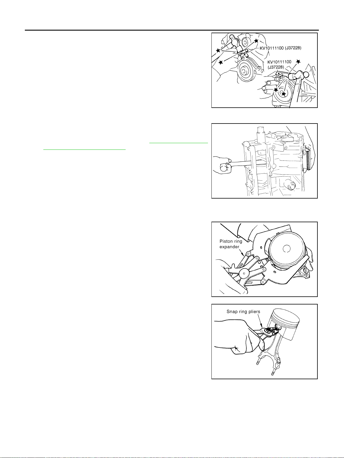
EM-124
[VQ35DE]
CYLINDER BLOCK
Revision: 2004 November 2004 FX35/FX45
12. Use a seal cutter (SST) to cut away liquid gasket and remove
rear oil seal retainer.
CAUTION:
● Be careful not to damage mounting surface.
● If rear oil seal retainer is removed, replace it with a new
one.
NOTE:
Rear oil seal and retainer make up a single part and are
removed as an assembly.
13. Remove baffle plate from main bearing beam (2WD model).
14. Remove piston and connecting rod assembly.
● Before removing piston and connecting rod assembly, check
connecting rod side clearance. Refer to EM-136, "
CONNECT-
ING ROD SIDE CLEARANCE" .
a. Position crankshaft pin corresponding to connecting rod to be
removed onto the bottom dead center.
b. Remove connecting rod cap.
c. Using a hammer handle or similar tool, push piston and connect-
ing rod assembly out to cylinder head side.
15. Remove connecting rod bearings from connecting rod and con-
necting rod cap.
CAUTION:
When removing them, note the installation position. Keep them in the correct order.
16. Remove piston rings form piston.
● Use a piston ring expander (commercial service tool).
CAUTION:
● When removing piston rings, be careful not to damage
piston.
● Be careful not to damage piston rings by expanding
them excessively.
17. Remove piston from connecting rod as follows.
a. Using a snap ring pliers, remove snap ring.
SEM830E
EMQ0191D
PBIC0087E
PBIC0088E
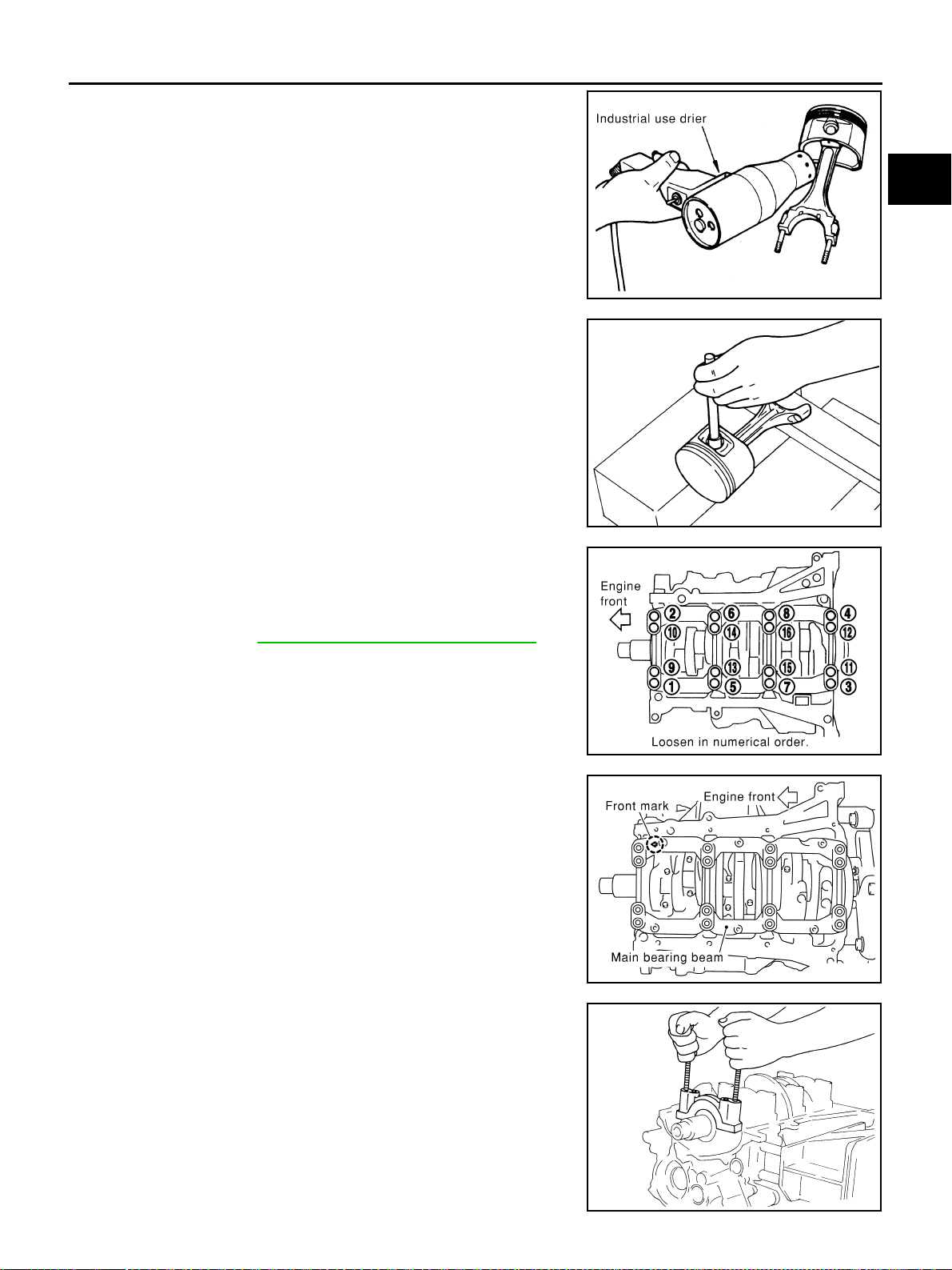
CYLINDER BLOCK
EM-125
[VQ35DE]
C
D
E
F
G
H
I
J
K
L
M
A
EM
Revision: 2004 November 2004 FX35/FX45
b. Heat piston to 60 to 70°C (140 to 158°F) with industrial use drier
or equivalent.
c. Push out piston pin with stick of outer diameter approximately 20
mm (0.79 in).
18. Remove main bearing cap bolt.
NOTE:
Use TORX socket (size E14).
● Before loosening main bearing cap bolts, measure crankshaft
end play. Refer to EM-136, "
CRANKSHAFT END PLAY" .
● Loosen them in the numerical order shown in the figure in
several different steps.
19. Remove main bearing beam.
20. Remove main bearing cap.
● Using main bearing cap bolts, remove main bearing cap while
shaking it back-and-forth.
21. Remove crankshaft.
22. Remove main bearings and thrust bearings from cylinder block
and main bearing cap.
CAUTION:
Identify installation positions, and store them without mix-
ing them up.
23. Remove oil jet.
PBIC0089E
PBIC0262E
PBIC0909E
PBIC0881E
EMQ0195D
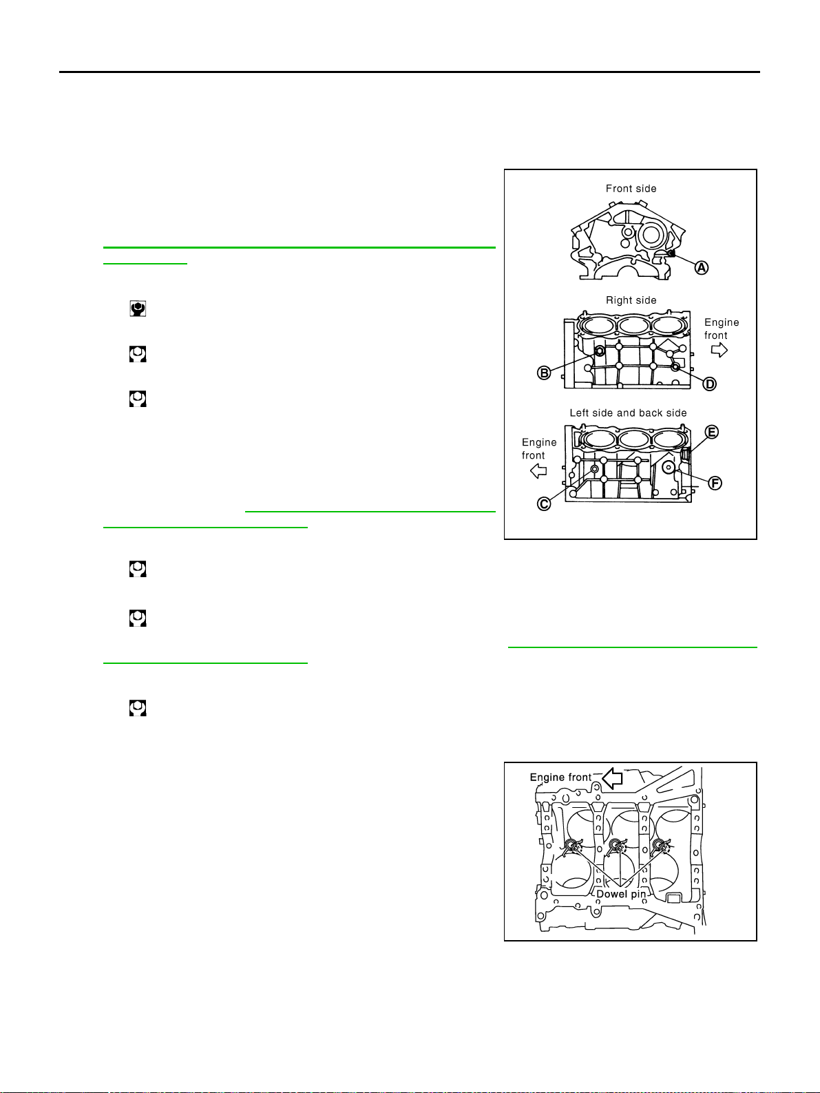
EM-126
[VQ35DE]
CYLINDER BLOCK
Revision: 2004 November 2004 FX35/FX45
ASSEMBLY
1. Fully air-blow engine coolant and engine oil passages in cylinder block, cylinder bore and crankcase to
remove any foreign material.
CAUTION:
Use a goggles to protect your eye.
2. Install each water drain plug to cylinder block as shown in the
figure.
● Apply liquid gasket to the thread of water drain plugs.
Use Genuine RTV Silicone Sealant or equivalent. Refer to
GI-48, "
RECOMMENDED CHEMICAL PRODUCTS AND
SEALANTS" .
3. Install each plug to cylinder block as shown in the figure if
removed.
● Apply liquid gasket to the thread of plugs and install plugs with
new gaskets.
Use Genuine High Strength Thread Locking Sealant or
equivalent. Refer to GI-48, "
RECOMMENDED CHEMICAL
PRODUCTS AND SEALANTS" .
Use Genuine RTV Silicone Sealant or equivalent. Refer to GI-48, "
RECOMMENDED CHEMICAL
PRODUCTS AND SEALANTS" .
4. Install oil jet.
● Insert oil jet dowel pin into cylinder block dowel pin hole, and
tighten mounting bolts.
Water drain plug (front) “A”:
: 9.8 N·m (1.0 kg-m, 87 in-lb)
Water drain plug (RH) “B”:
: 19.6 N·m (2.0 kg-m, 14 ft-lb)
Water drain plug (LH) “C”:
: 19.6 N·m (2.0 kg-m, 14 ft-lb)
Plug (RH) “D”:
: 12.3 N·m (1.3 kg-m, 9 ft-lb)
Plug (rear) “E”:
: 62 N·m (6.3 kg-m, 46 ft-lb)
Plug (LH) “F”:
: 62 N·m (6.3 kg-m, 46 ft-lb)
PBIC2610E
PBIC0898E
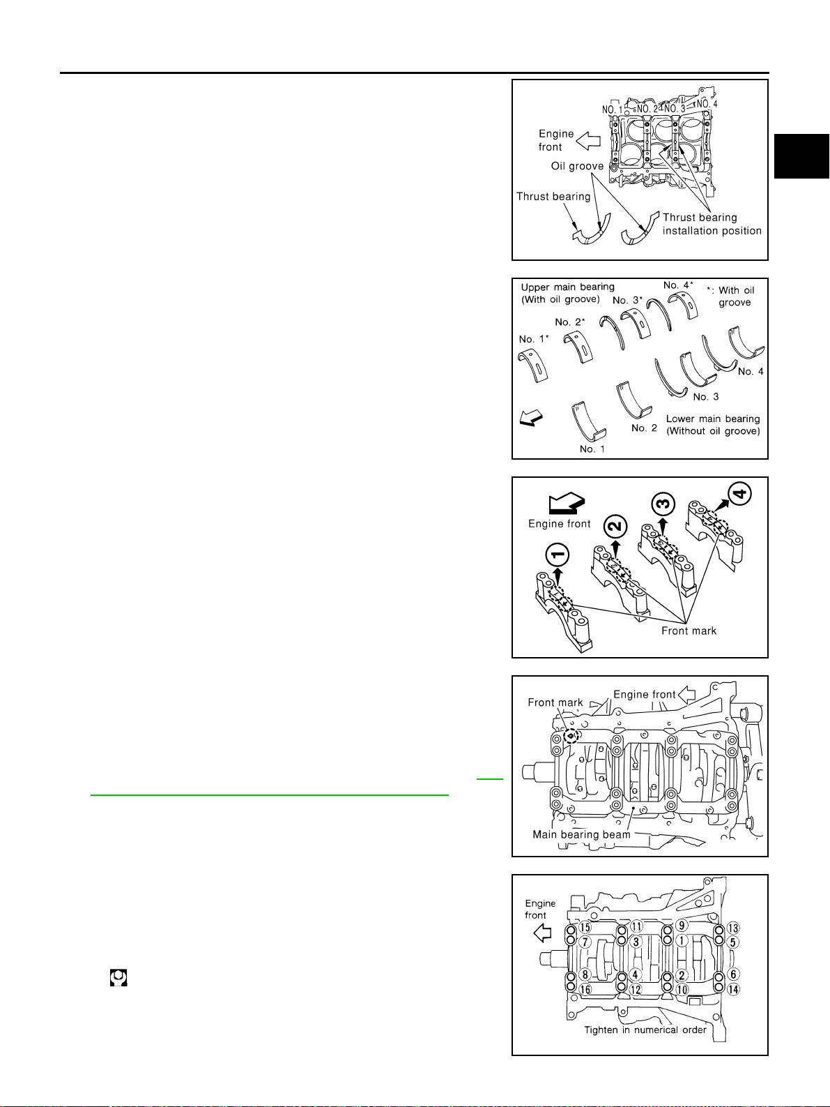
CYLINDER BLOCK
EM-127
[VQ35DE]
C
D
E
F
G
H
I
J
K
L
M
A
EM
Revision: 2004 November 2004 FX35/FX45
5. Install main bearings and thrust bearings.
a. Remove dust, dirt, and engine oil on the bearing mating sur-
faces of cylinder block and main bearing cap.
b. Install thrust bearings to the both sides of No. 3 journal housing
on cylinder block and main bearing cap.
● Install thrust bearings with the oil groove facing to the crank-
shaft arm (outside).
● Install bearing with a projection on one end on cylinder block,
and bearing with a projection at center on cap. Align each pro-
jection with mating notch.
c. Install main bearings paying attention to the direction.
● Main bearing with an oil hole and groove goes on cylinder
block. The one without them goes on main bearing cap.
● Before installing bearings, apply engine oil to the bearing sur-
face (inside). Do not apply engine oil to the back surface, but
thoroughly clean it.
● When installing, align the bearing stopper to the notch.
● Ensure the oil holes on cylinder block and those on the corre-
sponding bearing are aligned.
6. Install crankshaft to cylinder block.
● While turning crankshaft by hand, make sure it turns
smoothly.
7. Install main bearing cap.
● Main bearing caps are identified by identification mark cast on
them. For installation, face front mark to front side.
NOTE:
Main bearing cap cannot be replaced as a single part,
because it is machined together with cylinder block.
8. Install main bearing beam.
● Install main bearing beam with front mark facing downward
(oil pan side).
● Install main bearing beam with front mark facing front of
engine.
9. Inspect outer diameter of main bearing cap bolt. Refer to EM-
144, "MAIN BEARING CAP BOLT OUTER DIAMETER" .
10. Install main bearing cap bolt.
a. Apply new engine oil to threads and seat surfaces of mounting
bolts.
b. Tighten bolts in numerical order with tightening torque in several
different steps.
PBIC0807E
SEM175F
SEM456G
PBIC0881E
: 35.3 N·m (3.6 kg-m, 26 ft-lb)
SEM851E
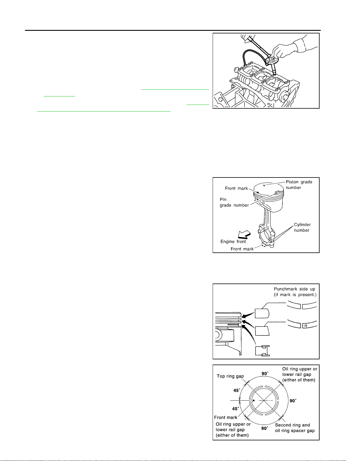
EM-128
[VQ35DE]
CYLINDER BLOCK
Revision: 2004 November 2004 FX35/FX45
c. Turn all bolts another “90” degrees clockwise (Angle tightening).
CAUTION:
Use an angle wrench [SST: KV10112100 (BT8653-A)] to
check tightening angle. Do not make judgment by visual
inspection.
● After installing mounting bolts, make sure that crankshaft can
be rotated smoothly by hand.
● Check crankshaft end play. Refer to EM-136, "CRANKSHAFT
END PLAY" .
11. Inspect outer diameter of connecting rod bolt. Refer to EM-144,
"CONNECTING ROD BOLT OUTER DIAMETER" .
12. Install piston to connecting rod.
a. Using a snap ring pliers (commercial service tool), install a new snap ring to the groove of the piston rear
side.
● Insert it fully into groove to install.
b. Install piston to connecting rod.
● Using an industrial drier or similar tool, heat piston until piston pin can be pushed in by hand without
excess force [approx. 60 to 70 °C (140 to 158 °F)]. From the front to the rear, insert piston pin into pis-
ton and connecting rod.
● Assemble so that the front mark on the piston crown and the
cylinder number on connecting rod are positioned as shown in
the figure.
c. Install a new snap ring to the groove of the piston front side.
● Insert it fully into groove to install.
● After installing, make sure connecting rod moves smoothly.
13. Using a piston ring expander (commercial service tool), install piston rings.
CAUTION:
Be careful not to damage piston.
● If there is stamped mark on ring, mount it with marked side
up.
NOTE:
If there is no stamp on ring, no specific orientation is required
for installation.
● Position each ring with the gap as shown in the figure refer-
ring to the piston front mark.
PBIC0921E
SEM838F
Stamped mark:
Top ring : —
Second ring : “R”
SEM757G
PBIC0808E
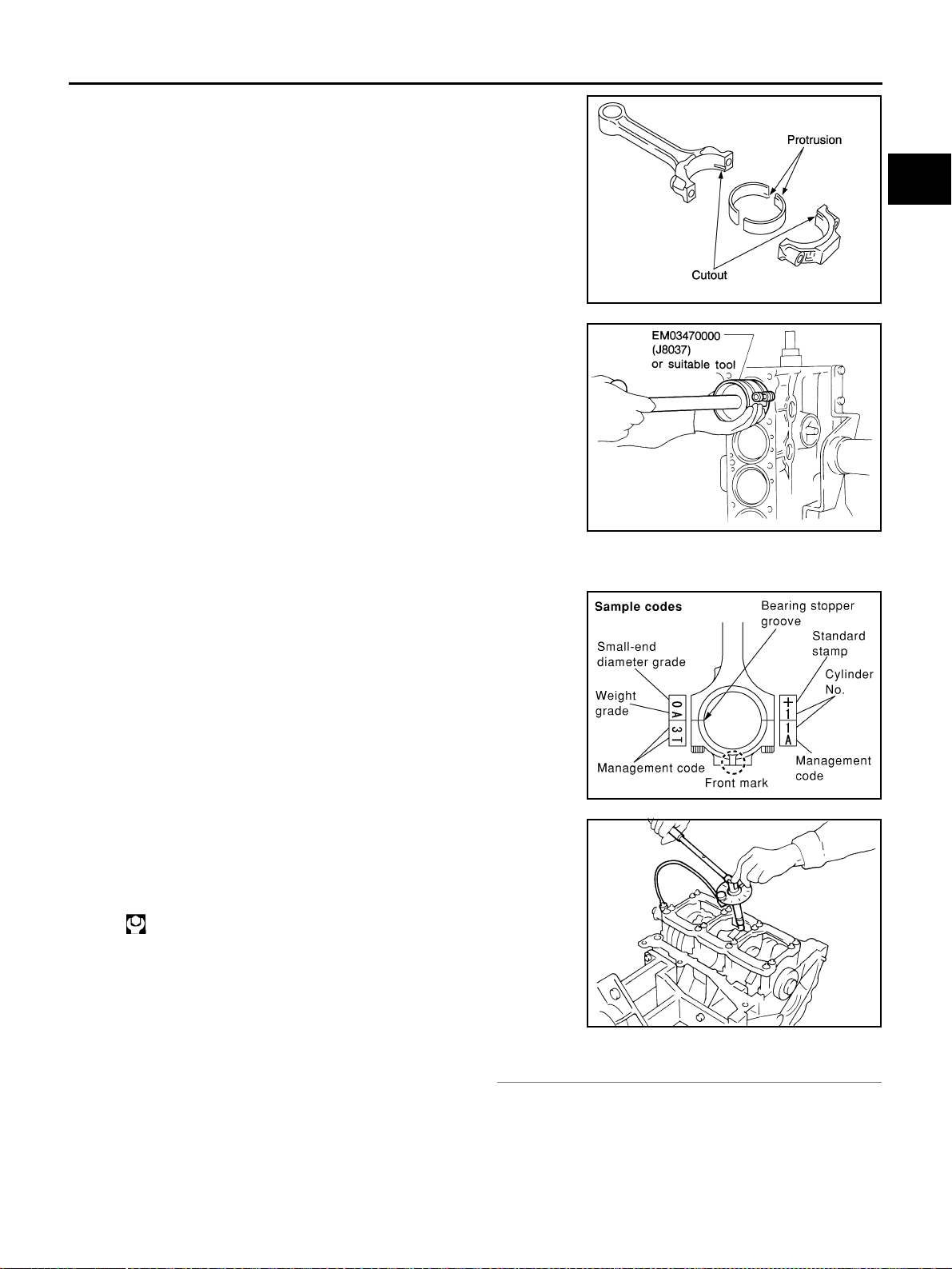
CYLINDER BLOCK
EM-129
[VQ35DE]
C
D
E
F
G
H
I
J
K
L
M
A
EM
Revision: 2004 November 2004 FX35/FX45
14. Install connecting rod bearings to connecting rod and connect-
ing rod cap.
● When installing connecting rod bearings, apply engine oil to
the bearing surface (inside). Do not apply engine oil to the
back surface, but thoroughly clean it.
● When installing, align connecting rod bearing stopper protru-
sion with the cutout of connecting rod to install.
● Check the oil hole on connecting rod and that on the corre-
sponding bearing are aligned.
15. Install piston and connecting rod assembly to crankshaft.
● Position crankshaft pin corresponding to connecting rod to be
installed onto the bottom dead center.
● Apply engine oil sufficiently to cylinder bore, piston and crank-
shaft pin.
● Match cylinder position with the cylinder number on connect-
ing rod to install.
● Using a piston ring compressor (SST) or suitable tool, install
piston with the front mark on the piston crown facing the front
of engine.
CAUTION:
Be careful not to damage cylinder wall and crankshaft pin, resulting from an interference of con-
necting rod big end.
16. Install connecting rod cap.
● Match the stamped cylinder number marks on connecting rod
with those on cap to install.
● Be sure that front mark on connecting rod cap is facing front
of engine.
17. Tighten connecting rod bolt as follows.
a. Apply engine oil to the threads and seats of connecting rod
bolts.
b. Tighten bolts.
c. Then tighten all bolts “90” degrees clockwise (Angle tightening).
CAUTION:
Always use an angle wrench [SST: KV10112100 (BT8653-
A)]. Avoid tightening based on visual check alone.
● After tightening bolt, make sure that the crankshaft rotates
smoothly.
● Check the connecting rod side clearance. Refer to EM-136, "CONNECTING ROD SIDE CLEARANCE"
18. Install baffle plate to main bearing beam.
PBIC0266E
SEM620
PBIC0809E
: 19.6 N·m (2.0 kg-m, 14 ft-lb)
SEM953E

EM-130
[VQ35DE]
CYLINDER BLOCK
Revision: 2004 November 2004 FX35/FX45
19. Install rear oil seal retainer to cylinder block.
● Apply new engine oil to the oil and dust seal lips.
● Apply liquid gasket to rear oil seal retainer using tube presser
[SST: WS39930000 ( - )] as shown in the figure.
Use Genuine RTV Silicone Sealant or equivalent. Refer to
GI-48, "
RECOMMENDED CHEMICAL PRODUCTS AND
SEALANTS" .
CAUTION:
Replace with the new parts.
NOTE:
Rear oil seal with rear oil seal retainer.
20. Install pilot converter using suitable tool.
● Outer diameter of drift.
● Press-fit pilot converter with its chamfer facing crankshaft as
shown in the figure.
21. Install drive plate.
● Install drive plate and reinforcement plate as shown in figure.
● Secure crankshaft using a ring gear stopper [SST:
KV1011770 (J44716)].
● Tighten the installation bolts crosswise over several times.
PBIC0922E
Pilot converter : Approx. 33 mm (1.30 in)
PBIC0899E
SEM537E
PBIC0910E
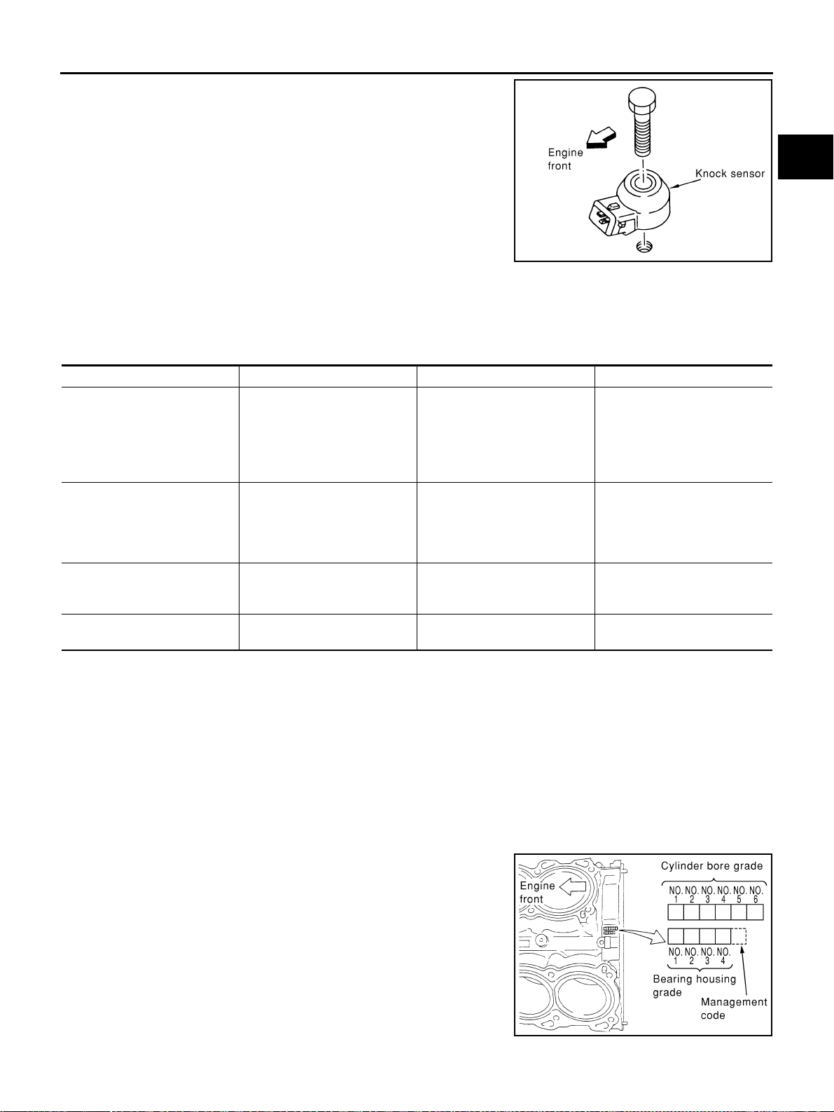
CYLINDER BLOCK
EM-131
[VQ35DE]
C
D
E
F
G
H
I
J
K
L
M
A
EM
Revision: 2004 November 2004 FX35/FX45
22. Install knock sensor.
● Install knock sensor so that connector faces front of engine.
● After installing knock sensor, connect harness connector, and
lay it out to rear of engine.
CAUTION:
● Do not tighten mounting bolts while holding connector.
● If any impact by dropping is applied to knock sensor,
replace it with new one.
NOTE:
● Make sure that there is no foreign material on the cylinder
block mating surface and the back surface of knock sensor.
● Make sure that knock sensor does not interfere with other parts.
23. Install followings in reverse order of removal.
How to Select Piston and Bearing ABS00FPI
DESCRIPTION
*For the service parts, the grade for fitting cannot be selected between a piston pin and a connecting rod.
(Only 0 grade is available.) The information at the shipment from the plant is described as a reference.
● The identification grade stamped on each part is the grade for the dimension measured in new condition.
This grade cannot apply to reused parts.
● For reused or repaired parts, measure the dimension accurately. Determine the grade by comparing the
measurement with the values of each selection table.
● For details of the measurement method of each part, the reuse standards and the selection method of the
selective fitting parts, refer to the text.
HOW TO SELECT PISTON
When New Cylinder Block Is Used
Check cylinder bore grade (“1”, “2”, or “3”) on rear side of cylinder
block, and select a piston of the same grade.
NOTE:
Piston is available with piston pin as a set for the service part. (Only
“0” grade piston pin is available.)
PBIC0810E
Selection points Selection parts Selection items Selection methods
Between cylinder block and
crankshaft
Main bearing
Main bearing grade
(bearing thickness)
Determined by match of cylin-
der block bearing housing
grade (inner diameter of hous-
ing) and crankshaft journal
grade (outer diameter of jour-
nal)
Between crankshaft and con-
necting rod
Connecting rod bearing
Connecting rod bearing grade
(bearing thickness)
Combining service grades for
connecting rod big end inner
diameter and crankshaft pin
outer diameter determine con-
necting rod bearing selection.
Between cylinder block and pis-
ton
Piston and piston pin assembly
(Piston is available together
with piston pin as an assembly.)
Piston grade
(piston outer diameter)
Piston grade = cylinder bore
grade (inner diameter of bore)
*Between piston and connect-
ing rod
———
PBIC0811E
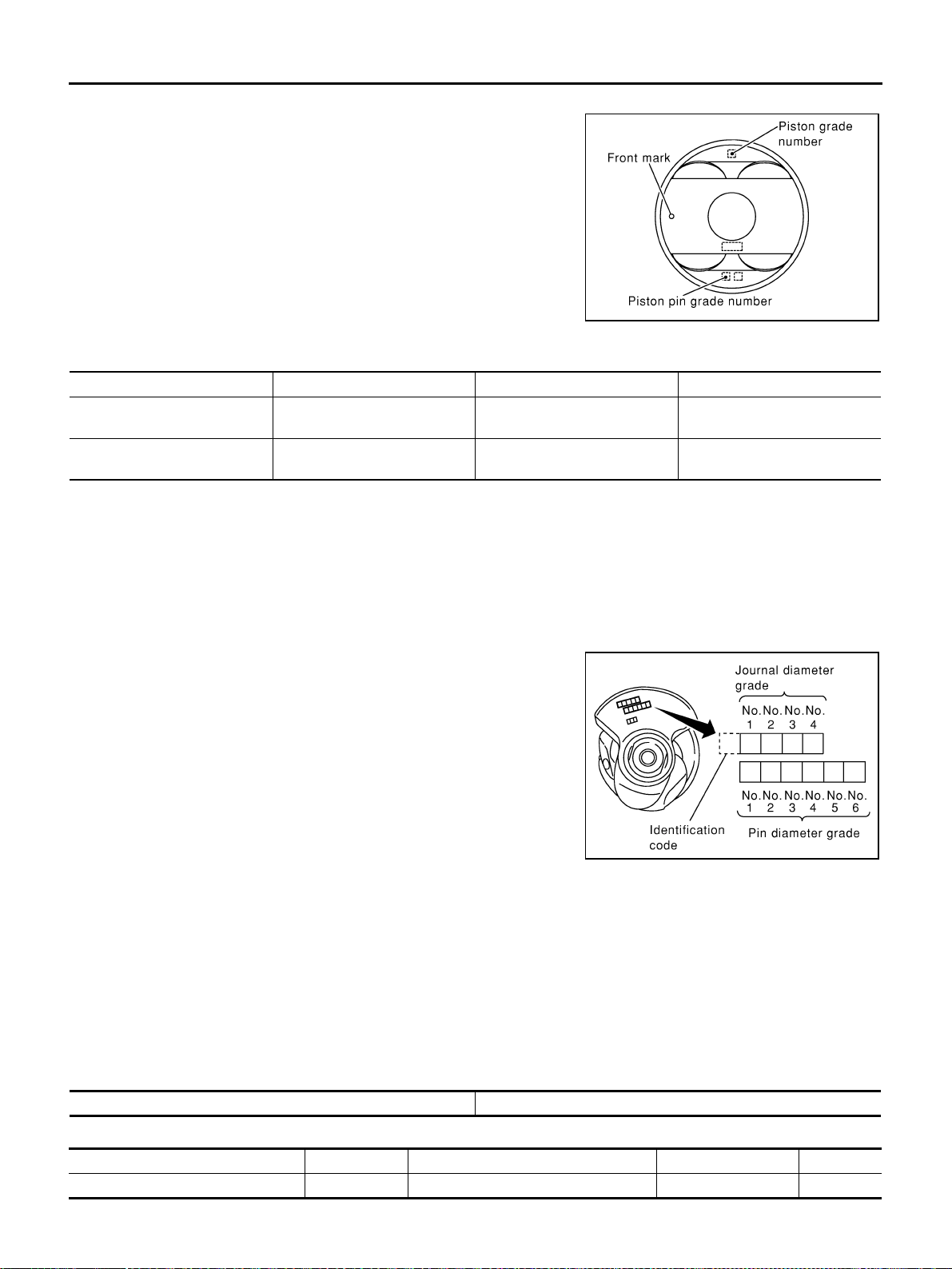
EM-132
[VQ35DE]
CYLINDER BLOCK
Revision: 2004 November 2004 FX35/FX45
When Cylinder Block Is Reused
1. Measure the cylinder block bore inner diameter.
2. Determine the bore grade by comparing the measurement with
the values under the cylinder bore inner diameter of the “Piston
Selection Table”.
3. Select piston of the same grade.
Piston Selection Table
Unit: mm (in)
NOTE:
● Piston is available together with piston pin as an assembly.
● Piston pin (piston pin bore) grade is provided only for the parts installed at the plant. For service parts, no
piston pin grades can be selected. (Only “0” grade is available.)
● No second grade mark is available on piston.
HOW TO SELECT CONNECTING ROD BEARING
When New Connecting Rod and Crankshaft are Used
Check pin diameter grade number (“0”, “1”, or “2”) stamped in front
of crankshaft, and select connecting rod bearing of same grade
number.
NOTE:
There is no grading for connecting rod big end inner diameter.
When Crankshaft and Connecting Rod Are Reused
1. Measure dimensions of the big end inner diameter of connecting rod and outer diameter of crankshaft pin
individually.
2. Confirm the big end inner diameter of connecting rod is within the standard value.
3. Apply the measured dimension to the “Connecting Rod Bearing Selection Table”.
4. Determine the grade of crankshaft pin diameter grade by comparing the measurement with the values
under the crankshaft pin outer diameter of the “Connecting Rod Bearing Selection Table”.
5. Select connecting rod bearing of the same grade.
Connecting Rod Bearing Selection Table
Unit: mm (in)
Unit: mm (in)
PBIC0812E
Grade 1 2 (or no mark) 3
Inner diameter of cylinder bore
95.500 / 95.510
(3.7598 / 3.7602)
95.510 / 95.520
(3.7602 / 3.7606)
95.520 / 95.530
(3.7606 / 3.7610)
Outer diameter of piston
95.480 / 95.490
(3.7590 / 3.7594)
95.490 / 95.500
(3.7594 / 3.7598)
95.500 / 95.510
(3.7598 / 3.7602)
SEM452G
Connecting rod big end inner diameter 55.000 - 55.013 (2.1654 - 2.1659)
Crankshaft pin outer diameter Grade (Mark) Dimension (Bearing thickness range) Bearing grade No. Color
51.968 - 51.974 (2.0460 - 2.0462) 0 1.500 - 1.503 (0.0591 - 0.0592) STD 0 Black
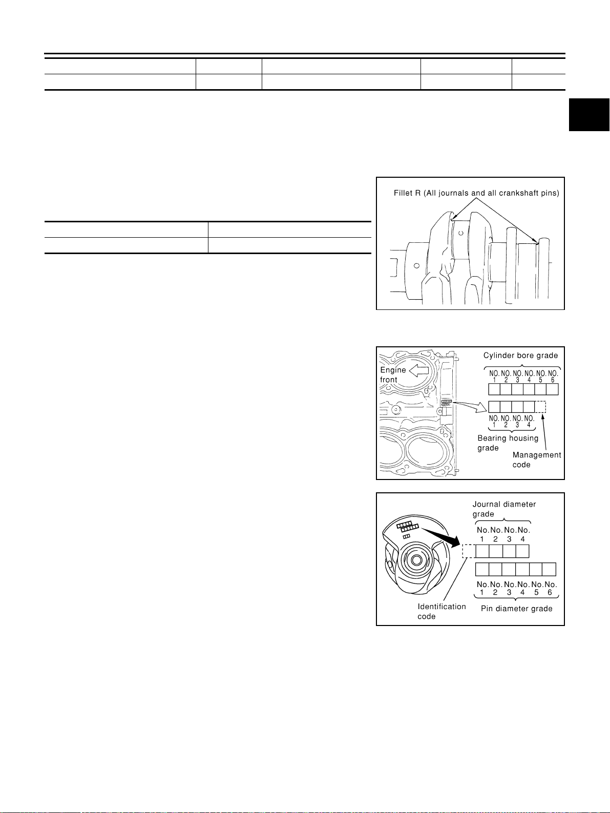
CYLINDER BLOCK
EM-133
[VQ35DE]
C
D
E
F
G
H
I
J
K
L
M
A
EM
Revision: 2004 November 2004 FX35/FX45
Undersize Bearings Usage Guide
● When the specified oil clearance is not obtained with standard size connecting rod bearings, use under-
size (US) bearings.
● When using undersize bearing, measure the bearing inner diameter with bearing installed, and grind
crankshaft pin so that the oil clearance satisfies the standard.
CAUTION:
In grinding crankshaft pin to use undersize bearings, keep the
fillet R [1.5 mm (0.059 in)].
Bearing undersize table
Unit: mm (in)
HOW TO SELECT MAIN BEARING
When New Cylinder Block and Crankshaft Are Used
1. “Main Bearing Selection Table” rows correspond to bearing
housing grade on rear left side of cylinder block.
2. Apply journal diameter grade stamped on crankshaft front side
to column in “Main Bearing Selection Table”.
3. Find sign (main bearing grade) at crossing of row and column in
“Main Bearing Selection Table”.
When Cylinder Block and Crankshaft Are Reused
1. Measure inner diameter of cylinder block main bearing housing and outer diameter of crankshaft journal.
2. Find measured dimension in “Cylinder block bearing housing inner diameter” row of “Main Bearing Selec-
tion Table”.
3. Find the measured dimension in “Crankshaft main journal diameter” column in the following selection
table.
4. Select main bearing grade at the point where selected row and column meet in following selection table.
51.962 - 51.968 (2.0457 - 2.0460) 1 1.503 - 1.506 (0.0592 - 0.0593) STD 1 Brown
51.956 - 51.962 (2.0455 - 2.0457) 2 1.506 - 1.509 (0.0593 - 0.0594) STD 2 Green
Size Thickness
US 0.25 (0.0098) 1.626 - 1.634 (0.0640 - 0.0643)
PBIC1908E
PBIC0811E
SEM452G
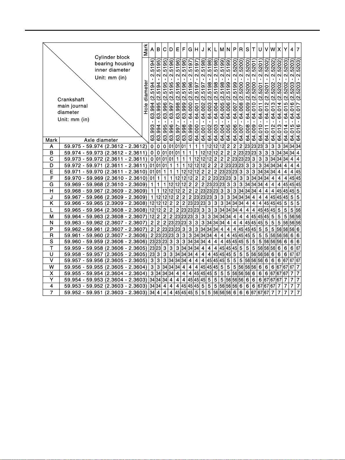
EM-134
[VQ35DE]
CYLINDER BLOCK
Revision: 2004 November 2004 FX35/FX45
Main Bearing Selection Table
PBIC0814E

CYLINDER BLOCK
EM-135
[VQ35DE]
C
D
E
F
G
H
I
J
K
L
M
A
EM
Revision: 2004 November 2004 FX35/FX45
Main Bearing Grade Table (All Journals)
Undersize Bearing Usage Guide
● Use undersize (US) bearing when oil clearance with standard size main bearing is not within specification.
● When using undersize (US) bearing, measure the bearing inner diameter with bearing installed, and grind
journal until oil clearance falls within specification.
CAUTION:
Keep fillet R [1.5 mm (0.059 in)] when grinding crankshaft jour-
nal in order to use undersize bearing (All journals).
Bearing undersize table
Unit: mm (in)
Grade number Thickness “T” mm (in) Width “W” mm (in)
Identification color
(UPR/LWR)
Remarks
0 2.000 - 2.003 (0.0787 - 0.0789)
19.9 - 20.1
(0.783 - 0.791)
Black
Grade is the same for
upper and lower bear-
ings.
1 2.003 - 2.006 (0.0789 - 0.0790) Brown
2 2.006 - 2.009 (0.0790 - 0.0791) Green
3 2.009 - 2.012 (0.0791 - 0.0792) Yellow
4 2.012 - 2.015 (0.0792 - 0.0793) Blue
5 2.015 - 2.018 (0.0793 - 0.0794) Pink
6 2.018 - 2.021 (0.0794 - 0.0796) Purple
7 2.021 - 2.024 (0.0796 - 0.0797) White
01
UPP 2.003 - 2.006 (0.0789 - 0.0790)
Brown/Black
Grade is different for
upper and lower bear-
ings.
LWR 2.000 - 2.003 (0.0787 - 0.0789)
12
UPR 2.006 - 2.009 (0.0790 - 0.0791)
Green/Brown
LWR 2.003 - 2.006 (0.0789 - 0.0790)
23
UPR 2.009 - 2.012 (0.0791 - 0.0792)
Yellow/Green
LWR 2.006 - 2.009 (0.0790 - 0.0791)
34
UPR 2.012 - 2.015 (0.0792 - 0.0793)
Blue/Yellow
LWR 2.009 - 2.012 (0.0791 - 0.0792)
45
UPR 2.015 - 2.018 (0.0793 - 0.0794)
Pink/Blue
LWR 2.012 - 2.015 (0.0792 - 0.0793)
56
UPR 2.018 - 2.021 (0.0794 - 0.0796)
Purple/Pink
LWR 2.015 - 2.018 (0.0793 - 0.0794)
67
UPR 2.021 - 2.024 (0.0796 - 0.0797)
White/Purple
LWR 2.018 - 2.021 (0.0794 - 0.0796)
Size Thickness
US 0.25 (0.0098) 2.132 - 2.140 (0.0839 - 0.0843)
PBIC1908E
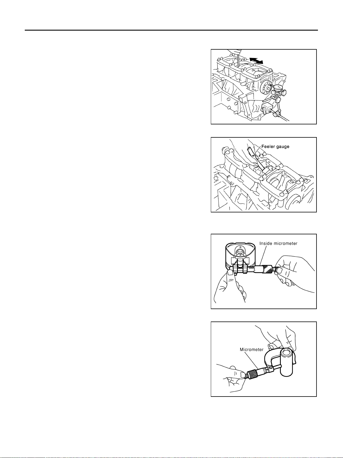
EM-136
[VQ35DE]
CYLINDER BLOCK
Revision: 2004 November 2004 FX35/FX45
Inspection After Disassembly ABS004XJ
CRANKSHAFT END PLAY
● Using a dial gauge, measure the clearance between thrust bear-
ings and crankshaft arm when crankshaft is moved fully forward
or backward.
● If the measured value exceeds the limit, replace thrust bearings,
and measure again. If it still exceeds the limit, replace crank-
shaft also.
CONNECTING ROD SIDE CLEARANCE
● Measure side clearance between connecting rod and crankshaft
arm with feeler gauge.
● If the measured value exceeds the limit, replace connecting rod,
and measure again. If it still exceeds the limit, replace crank-
shaft also.
PISTON TO PISTON PIN OIL CLEARANCE
Piston Pin Hole Diameter
Measure the hole diameter of piston pin hole with an inside
micrometer.
Piston Pin Outer Diameter
Measure outer diameter of piston pin with a micrometer.
Standard : 0.10 - 0.25 mm (0.0039 - 0.0098 in)
Limit : 0.30 mm (0.0118 in)
EMQ0196D
Standard : 0.20 - 0.35 mm (0.0079 - 0.0138 in)
Limit : 0.40 mm (0.0157 in)
PBIC0815E
Standard : 21.993 - 22.005 mm (0.8659 - 0.8663 in)
PBIC0116E
Standard : 21.989 - 22.001 mm (0.8657 - 0.8662 in)
PBIC0117E

CYLINDER BLOCK
EM-137
[VQ35DE]
C
D
E
F
G
H
I
J
K
L
M
A
EM
Revision: 2004 November 2004 FX35/FX45
Piston to Piston Pin Oil Clearance
(Piston pin oil clearance) = (Piston pin hole diameter) – (Piston pin outer diameter)
● If clearance exceeds specification, replace piston/piston pin assembly with reference to specification of
each parts.
● When replacing piston/piston pin assembly, refer to EM-140, "PISTON TO CYLINDER BORE CLEAR-
ANCE" .
PISTON RING SIDE CLEARANCE
● Measure side clearance of piston ring and piston ring groove
with feeler gauge.
● If the measured value exceeds the limit, replace piston ring, and measure again. If it still exceeds the limit,
replace piston also.
PISTON RING END GAP
● Check if inner diameter of cylinder bore is within specification.
Refer to EM-140, "
PISTON TO CYLINDER BORE CLEAR-
ANCE" .
● Insert piston ring until middle of cylinder with piston, and mea-
sure gap.
● If out of specification, replace piston ring. If gap still exceeds the limit even with a new ring, re-bore cylin-
der and use oversized piston and piston ring.
Standard : 0.002 - 0.006 mm (0.0001 - 0.0002 in)
Standard:
Top ring : 0.045 - 0.080 mm (0.0018 - 0.0031 in)
2nd ring : 0.030 - 0.070 mm (0.0012 - 0.0028 in)
Oil ring : 0.065 - 0.135 mm (0.0026 - 0.0053 in)
Limit:
Top ring : 0.11 mm (0.0043 in)
2nd ring : 0.10 mm (0.004 in)
SEM024AA
Standard:
Top ring : 0.23 - 0.33 mm (0.0091 - 0.0130 in)
2nd ring : 0.33 - 0.48 mm (0.0130 - 0.0189 in)
Oil ring : 0.20 - 0.50 mm (0.0079 - 0.0197 in)
Limit:
Top ring : 0.54 mm (0.0213 in)
2nd ring : 0.80 mm (0.0315 in)
Oil ring : 0.95 mm (0.0374 in)
PBIC0118E
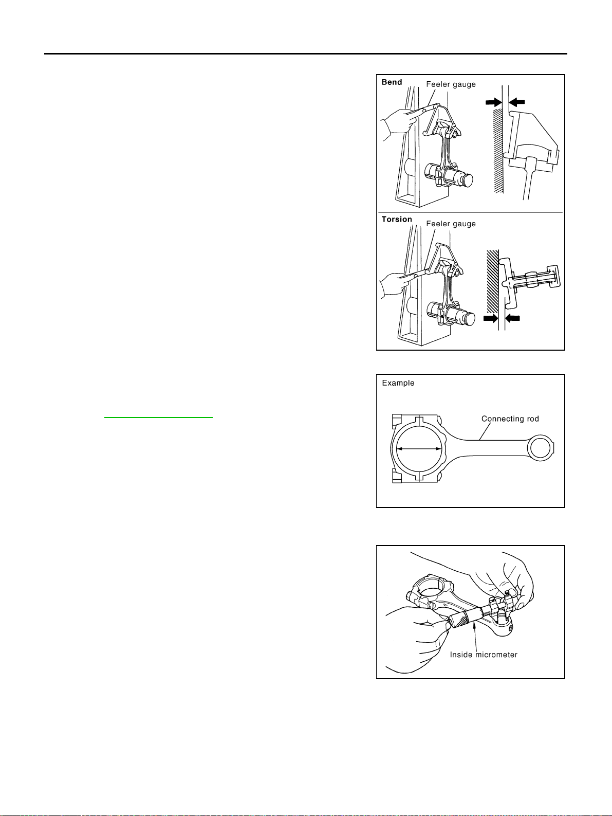
EM-138
[VQ35DE]
CYLINDER BLOCK
Revision: 2004 November 2004 FX35/FX45
CONNECTING ROD BEND AND TORSION
● Check with connecting rod aligner.
● If it exceeds the limit, replace connecting rod assembly.
CONNECTING ROD BEARING HOUSING DIAMETER (BIG END)
Install connecting rod cap without connecting rod bearing installed.
After tightening connecting rod bolt to the specified torque, measure
the connecting rod big end inner diameter using an inside microme-
ter. Refer to EM-126, "
ASSEMBLY" for the tightening procedure.
CONNECTING ROD BUSHING OIL CLEARANCE (SMALL END)
Piston Pin Bushing Inner Diameter (Small End)
Measure inner diameter of bushing.
Bend:
Limit : 0.15 mm (0.0059 in) per 100 mm (3.94 in) length
Torsion:
Limit : 0.30 mm (0.0118 in) per 100 mm (3.94 in) length
PBIC2077E
Standard : 55.000 - 55.013 mm (2.1654 - 2.1659 in)
PBIC1641E
Standard : 22.000 - 22.012 mm (0.8661 - 0.8666 in)
PBIC0120E
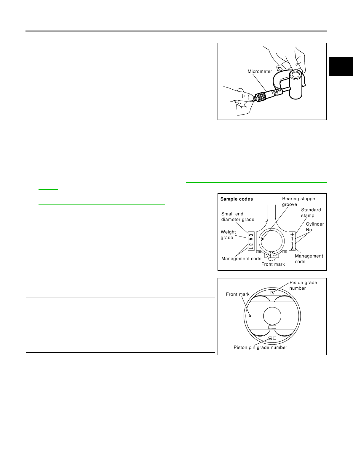
CYLINDER BLOCK
EM-139
[VQ35DE]
C
D
E
F
G
H
I
J
K
L
M
A
EM
Revision: 2004 November 2004 FX35/FX45
Piston Pin Outer Diameter
Measure outer diameter of piston pin.
Connecting Rod Bushing Oil Clearance (Small End)
(Connecting rod bushing oil clearance) = (Piston pin bushing inner diameter) – (Piston pin outer diameter)
● If the measured value exceeds the standard, replace connecting rod assembly and/or piston and piston
pin assembly.
● If replacing piston and piston pin assembly, refer to EM-140, "PISTON TO CYLINDER BORE CLEAR-
ANCE" .
● If replacing connecting rod assembly, refer to EM-142, "CON-
NECTING ROD BEARING OIL CLEARANCE" .
Factory installed parts grading:
Service parts apply only to grade “0”.
Unit: mm (in)
*: After installing in connecting rod
CYLINDER BLOCK DISTORTION
● Using a scraper, remove gasket on the cylinder block surface, and also remove engine oil, scale, carbon,
or other contamination.
CAUTION:
Be careful not to allow gasket flakes to enter engine oil or engine coolant passages.
Standard : 21.989 - 22.001 mm (0.8657 - 0.8662 in)
PBIC0117E
Standard : 0.005 - 0.017 mm (0.0002 - 0.0007 in)
Limit : 0.030 mm (0.0012 in)
PBIC0809E
Grade 0 1
Piston pin bushing inner
diameter*
22.000 - 22.006
(0.8661 - 0.8664)
22.006 - 22.012
(0.8664 - 0.8666)
Piston pin hole diameter
21.993 - 21.999
(0.8659 - 0.8661)
21.999 - 22. 005
(0.8661 - 0.8663)
Piston pin outer diameter
21.989 - 21.995
(0.8657- 0.8659)
21.995 - 22.001
(0.8659 - 0.8662)
PBIC0812E
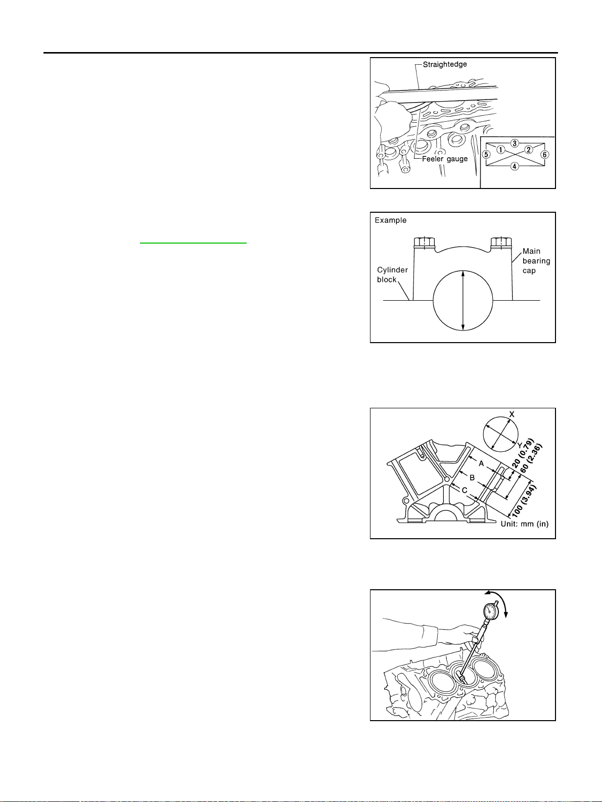
EM-140
[VQ35DE]
CYLINDER BLOCK
Revision: 2004 November 2004 FX35/FX45
● Measure the distortion on the block upper face at some different
points in 6 directions.
● If out of the distortion limit, replace cylinder block.
MAIN BEARING HOUSING INNER DIAMETER
● Install main bearing caps and main bearing beam with main
bearings removed, and tighten mounting bolts to the specified
torque. Refer to EM-126, "
ASSEMBLY" for the tightening proce-
dure.
● Using a bore gauge, measure the inner diameter of the main
bearing housing.
● If out of the standard, replace cylinder block and main bearing
caps as assembly.
NOTE:
Cylinder block cannot be replaced as single part, because it is
machined together with main bearing caps.
PISTON TO CYLINDER BORE CLEARANCE
Cylinder Bore Inner Diameter
● Using a bore gauge, measure cylinder bore for wear, out-of-
round and taper at 6 different points on each cylinder. (“X” and
“Y” directions at “A”, “B” and “C”) (“Y” is in longitudinal direction
of engine)
● If the measured value exceeds the limit, or if there are scratches
and/or seizure on the cylinder inner wall, hone or re-bore the
inner wall.
● An oversize piston is provided. When using an oversize piston,
re-bore cylinder so that the clearance of the piston-to-cylinder
bore satisfies the standard.
CAUTION:
When using oversize piston, use it for all cylinders with
oversize piston rings.
● When using an oversize piston, use it for all cylinders with over-
size piston rings.
Limit : 0.10 mm (0.0039 in)
SEM123C
Standard : 63.993 - 64.017 mm (2.5194 - 2.5203 in)
PBIC1643E
Standard inner diameter:
95.500 - 95.530 mm (3.7598 - 3.7610 in)
Wear limit:
0.20 mm (0.0079 in)
Out-of-round (Difference between “X” and “Y”):
Limit: 0.015 mm (0.0006 in)
Taper (Difference between “A” and “C”):
Limit: 0.010 mm (0.0004 in)
Oversize (Service) : 0.20 mm (0.0079 in)
PBIC0923E
SEM843E
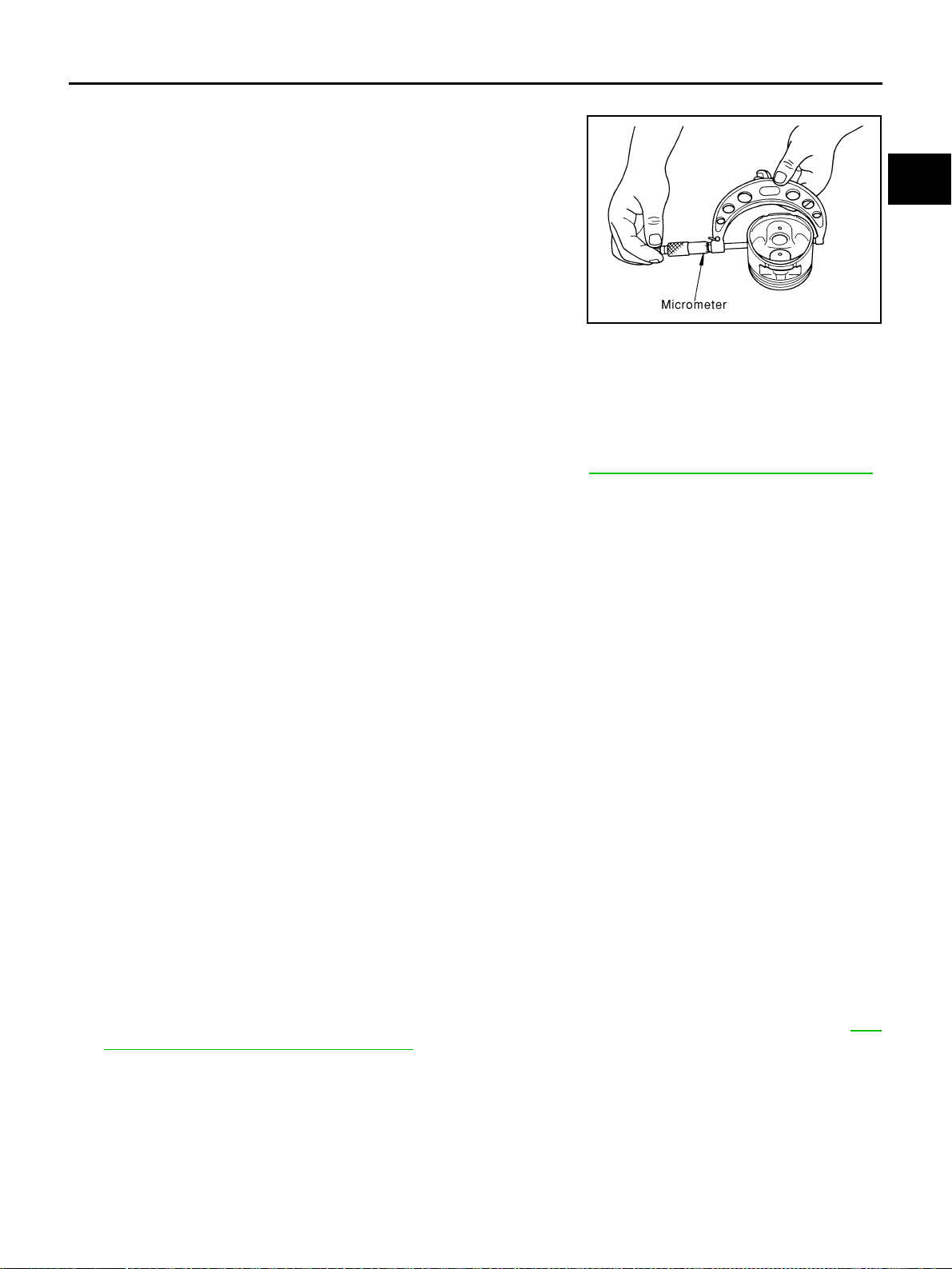
CYLINDER BLOCK
EM-141
[VQ35DE]
C
D
E
F
G
H
I
J
K
L
M
A
EM
Revision: 2004 November 2004 FX35/FX45
Piston Skirt Diameter
Measure piston skirt diameter using micrometer.
Piston-to-Cylinder Bore Clearance
● Calculate by piston skirt diameter and cylinder bore inner diameter (direction “X”, position “B”).
(Clearance) = (Cylinder bore inner diameter) – (Piston skirt diameter).
● If it exceeds the limit, replace piston/piston pin assembly. Refer to EM-131, "HOW TO SELECT PISTON" .
Re-Boring Cylinder Bore
1. Cylinder bore size is determined by adding piston-to-cylinder bore clearance to piston diameter “A”.
2. Install main bearing caps and main bearing beam, and tighten to the specified torque. Otherwise, cylinder
bores may be distorted in final assembly.
3. Cut cylinder bores.
NOTE:
● When any cylinder needs boring, all other cylinders must also be bored.
● Do not cut too much out of cylinder bore at a time. Cut only 0.05 mm (0.0020 in) or so in diameter at a
time.
4. Hone cylinders to obtain specified piston-to-cylinder bore clearance.
5. Measure finished cylinder bore for out-of-round and taper.
NOTE:
Measurement should be done after cylinder bore cools down.
CRANKSHAFT MAIN JOURNAL DIAMETER
● Measure outer diameter of crankshaft main journals with micrometer.
● If out of the standard, measure the main bearing oil clearance. Then use undersize bearing. Refer to EM-
143, "MAIN BEARING OIL CLEARANCE" .
Measure point
: Distance from the top 41.0 mm (1.614 in)
Standard
: 95.480 - 95.510 mm (3.7590 - 3.7602 in)
PBIC0125E
Standard : 0.010 - 0.030 mm (0.0004 - 0.0012 in)
Limit : 0.08 mm (0.0031 in)
Re-bored size calculation: “D” = “A” + “B” - “C”
where,
“D”: Bored diameter
“A”: Piston diameter as measured
“B”: Piston - to - cylinder bore clearance (standard value)
“C”: Honing allowance 0.02 mm (0.0008 in)
Standard : 59.951 - 59.975 mm (2.3603 - 2.3612 in) dia.

EM-142
[VQ35DE]
CYLINDER BLOCK
Revision: 2004 November 2004 FX35/FX45
CRANKSHAFT PIN JOURNAL DIAMETER
● Measure outer diameter of crankshaft pin journal with microme-
ter.
● If out of the standard, measure the connecting rod bearing oil
clearance. Then use undersize bearing. Refer to EM-142,
"CONNECTING ROD BEARING OIL CLEARANCE" .
CRANKSHAFT OUT-OF-ROUND AND TAPER
● Using a micrometer, measure the dimensions at “4” different
points shown in the figure on each journal and pin.
● Out-of-round is indicated by the difference in dimensions
between “X” and “Y” at “A” and “B”.
● Taper is indicated by the difference in dimension between “A”
and “B” at “X” and “Y”.
● If the measured value exceeds the limit, correct or replace crankshaft.
● If corrected, measure the bearing oil clearance of the corrected main journal and/or pin journal. Then
select the main bearing and/or connecting rod bearing. Refer to EM-143, "
MAIN BEARING OIL CLEAR-
ANCE" and/or EM-142, "CONNECTING ROD BEARING OIL CLEARANCE" .
CRANKSHAFT RUNOUT
● Place a V-block on a precise flat table to support journals on the
both end of crankshaft.
● Place a dial gauge straight up on No. 3 journal.
● While rotating crankshaft, read the movement of the pointer on
the dial gauge. (Total indicator reading)
● If it exceeds the limit, replace crankshaft.
CONNECTING ROD BEARING OIL CLEARANCE
Method by Calculation
● Install connecting rod bearings to connecting rod and connect-
ing rod bearing cap, and tighten connecting rod bolts to the
specified torque. Using a inside micrometer measure the inner
diameter of connecting rod bearing. Refer to EM-126, "
ASSEM-
BLY" for the tightening procedure.
(Oil clearance) = (Connecting rod bearing inner diameter) – (Crank-
shaft pin diameter)
Standard : 51.956 - 51.974 mm (2.0455 - 2.0462 in) dia.
PBIC0127E
Standard
Taper (Difference between “A” and “B”)
: Less than 0.002 mm (0.0001 in)
Out-of-round (Difference between “X” and “Y”)
: Less than 0.002 mm (0.0001 in)
SBIA0535E
Standard : Less than 0.025 mm (0.0010 in)
Limit : Less than 0.10 mm (0.0039 in)
SEM346D
Standard : 0.034 - 0.059 mm (0.0013 - 0.0023 in)
(actual clearance)
Limit : 0.070 mm (0.0028 in)
PBIC1642E
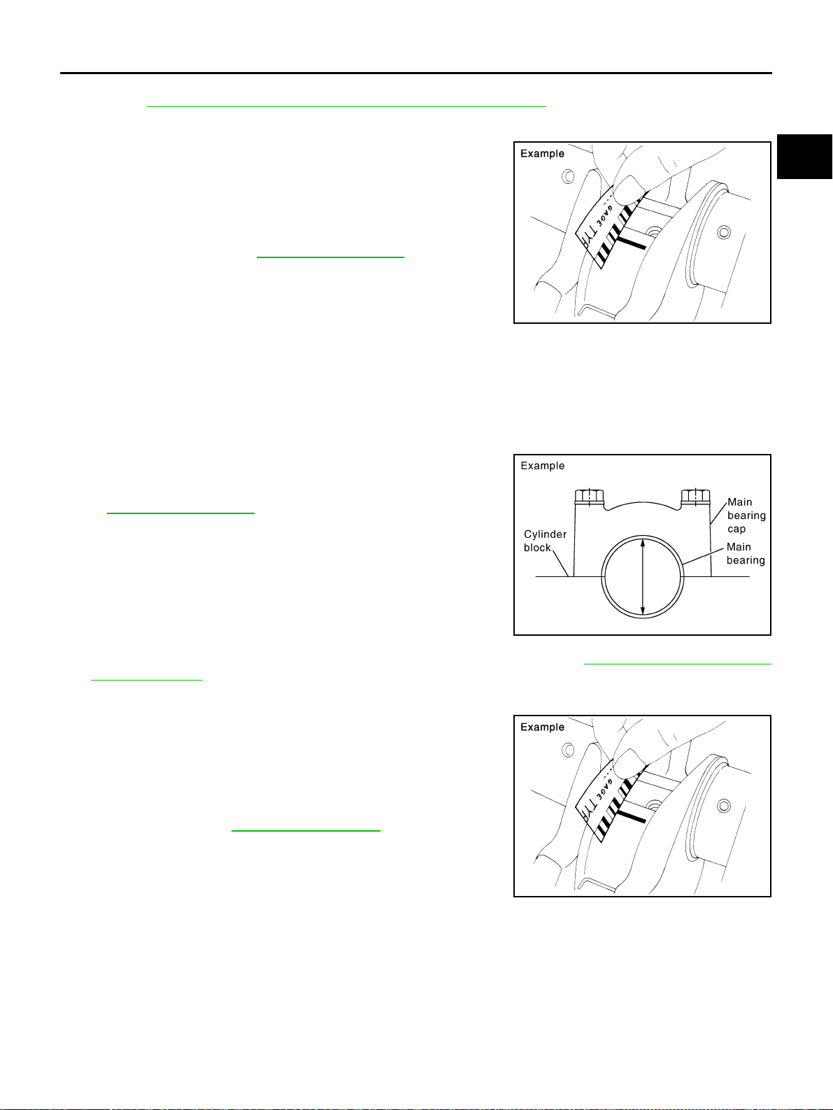
CYLINDER BLOCK
EM-143
[VQ35DE]
C
D
E
F
G
H
I
J
K
L
M
A
EM
Revision: 2004 November 2004 FX35/FX45
● If clearance cannot be adjusted within the standard, grind crankshaft pin and use undersized bearing.
Refer to EM-132, "
HOW TO SELECT CONNECTING ROD BEARING" .
Method of Using Plastigage
● Remove engine oil and dust on crankshaft pin and the surfaces
of each bearing completely.
● Cut a plastigage slightly shorter than bearing width, and place it
in crankshaft axial direction, avoiding oil holes.
● Install connecting rod bearings to connecting rod and connect-
ing rod bearing cap, and tighten connecting rod bolts to the
specified torque. Refer to EM-126, "
ASSEMBLY" for the tighten-
ing procedure.
CAUTION:
Never rotate crankshaft.
● Remove connecting rod cap and bearings, and using the scale
on the plastigage bag, measure the plastigage width.
NOTE:
The procedure when the measured value exceeds the limit is same as that described in the “Method by
Calculation”.
MAIN BEARING OIL CLEARANCE
Method by Calculation
● Install main bearings to cylinder block and main bearing cap.
Measure the main bearing inner diameter with bearing cap bolt
tightened with main bearing beam to the specified torque. Refer
to EM-126, "
ASSEMBLY" for the tightening procedure.
(Oil clearance) = (Main bearing inner diameter) – (Crankshaft main
journal diameter)
● If the measured value exceeds the limit, select main bearings
referring to the main bearing inner diameter and crankshaft jour-
nal outer diameter, so that the oil clearance satisfies the standard. Refer to EM-133, "
HOW TO SELECT
MAIN BEARING" .
Method of Using Plastigage
● Remove engine oil and dust on crankshaft journal and the sur-
faces of each bearing completely.
● Cut a plastigage slightly shorter than bearing width, and place it
in crankshaft axial direction, avoiding oil holes.
● Install main bearing to cylinder block and main bearing cap, and
tighten main bearing bolts with main bearing beam to the speci-
fied torque. Refer to EM-126, "
ASSEMBLY" for the tightening
procedure.
CAUTION:
Never rotate crankshaft.
● Remove bearing cap and bearings, and using the scale on the
plastigage bag, measure the plastigage width.
NOTE:
The procedure when the measured value exceeds the limit is same as that described in the “Method by
Calculation”.
PBIC1149E
Standard : 0.035 - 0.045 mm (0.0014 - 0.0018 in)
(actual clearance)
Limit : 0.065 mm (0.0026 in)
PBIC1644E
PBIC1149E
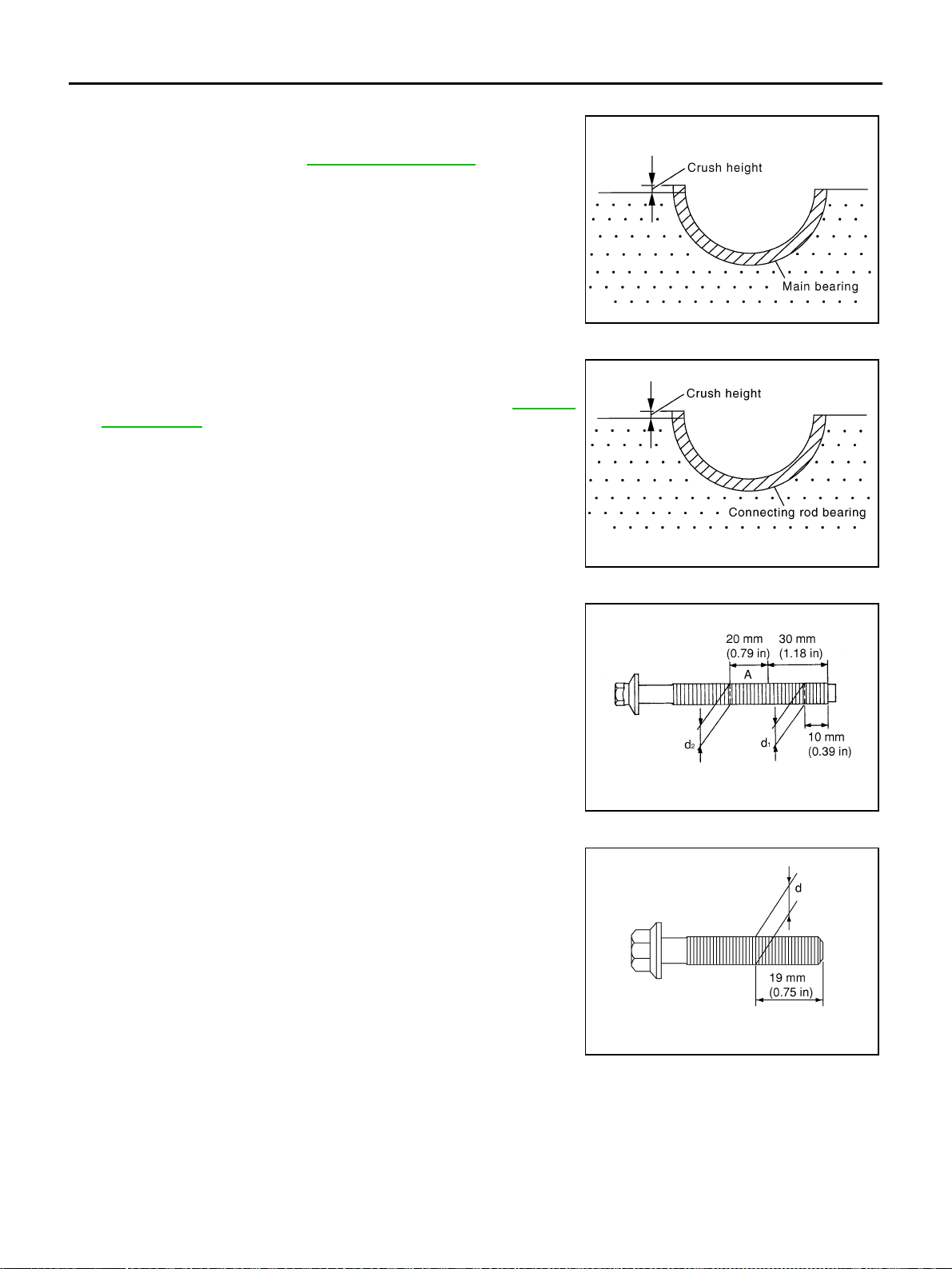
EM-144
[VQ35DE]
CYLINDER BLOCK
Revision: 2004 November 2004 FX35/FX45
MAIN BEARING CRUSH HEIGHT
● When main bearing cap is removed after being tightened to the
specified torque with main bearings installed, the tip end of bear-
ing must protrude. Refer to EM-126, "
ASSEMBLY" for the tight-
ening procedure.
● If the standard is not met, replace main bearings.
CONNECTING ROD BEARING CRUSH HEIGHT
● When connecting rod bearing cap is removed after being tight-
ened to the specified torque with connecting rod bearings
installed, the tip end of bearing must protrude. Refer to EM-126,
"ASSEMBLY" for the tightening procedure.
● If the standard is not met, replace connecting rod bearings.
MAIN BEARING CAP BOLT OUTER DIAMETER
● Measure outer diameters (“d1”, “d2”) at two positions shown in
the figure.
● Measure “d2” at a point within block “A”.
● When the value of “d1” - “d2” exceeds the limit (a large differ-
ence in dimensions), replace bolt with a new one.
CONNECTING ROD BOLT OUTER DIAMETER
● Measure outer diameter “d” at position shown in the figure.
● If reduction appears in a position other than “d”, regard it as “d”.
● When “d” exceeds the limit (when it becomes thinner), replace
bolt with a new one.
Standard : There must be crush height.
SEM502G
Standard : There must be crush height.
PBIC1646E
Limit : 0.11 mm (0.0051 in)
PBIC0911E
Standard : 7.90 - 8.00 mm (0.3110 - 0.3150 in)
Limit : 7.75 mm (0.3051 in)
PBIC0912E
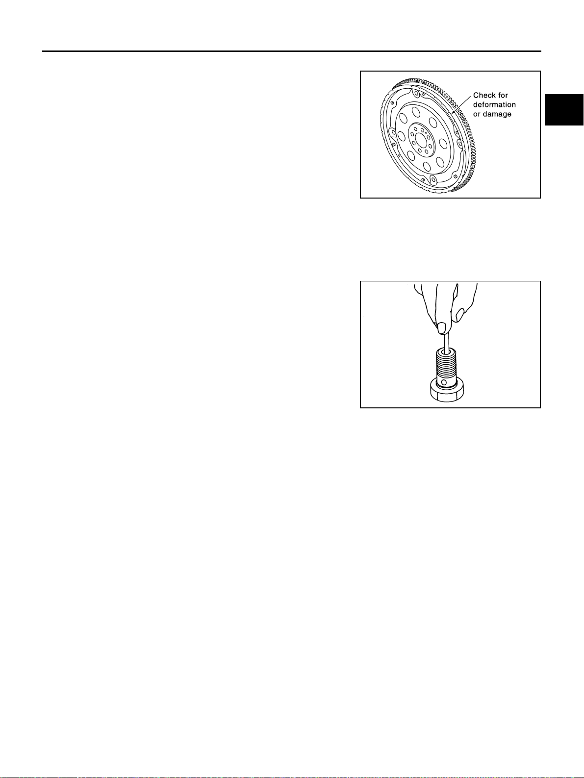
CYLINDER BLOCK
EM-145
[VQ35DE]
C
D
E
F
G
H
I
J
K
L
M
A
EM
Revision: 2004 November 2004 FX35/FX45
DRIVE PLATE
● Check drive plate and signal plate for deformation or damage.
CAUTION:
● Do not disassemble drive plate.
● Never place drive plate with signal plate facing down.
● When handling signal plate, take care not to damage or
scratch it.
● Handle signal plate in a manner that prevents it from
becoming magnetized.
● If anything is found, replace drive plate.
OIL JET
● Check nozzle for deformation and damage.
● Blow compressed air from nozzle, and check for clogs.
● If it is not satisfied, clean or replace oil jet.
OIL JET RELIEF VALVE
● Using a clean plastic stick, press check valve in oil jet relief
valve. Make sure that valve moves smoothly with proper reac-
tion force.
● If it is not satisfied, replace oil jet relief valve.
SEM760G
EMU0468D
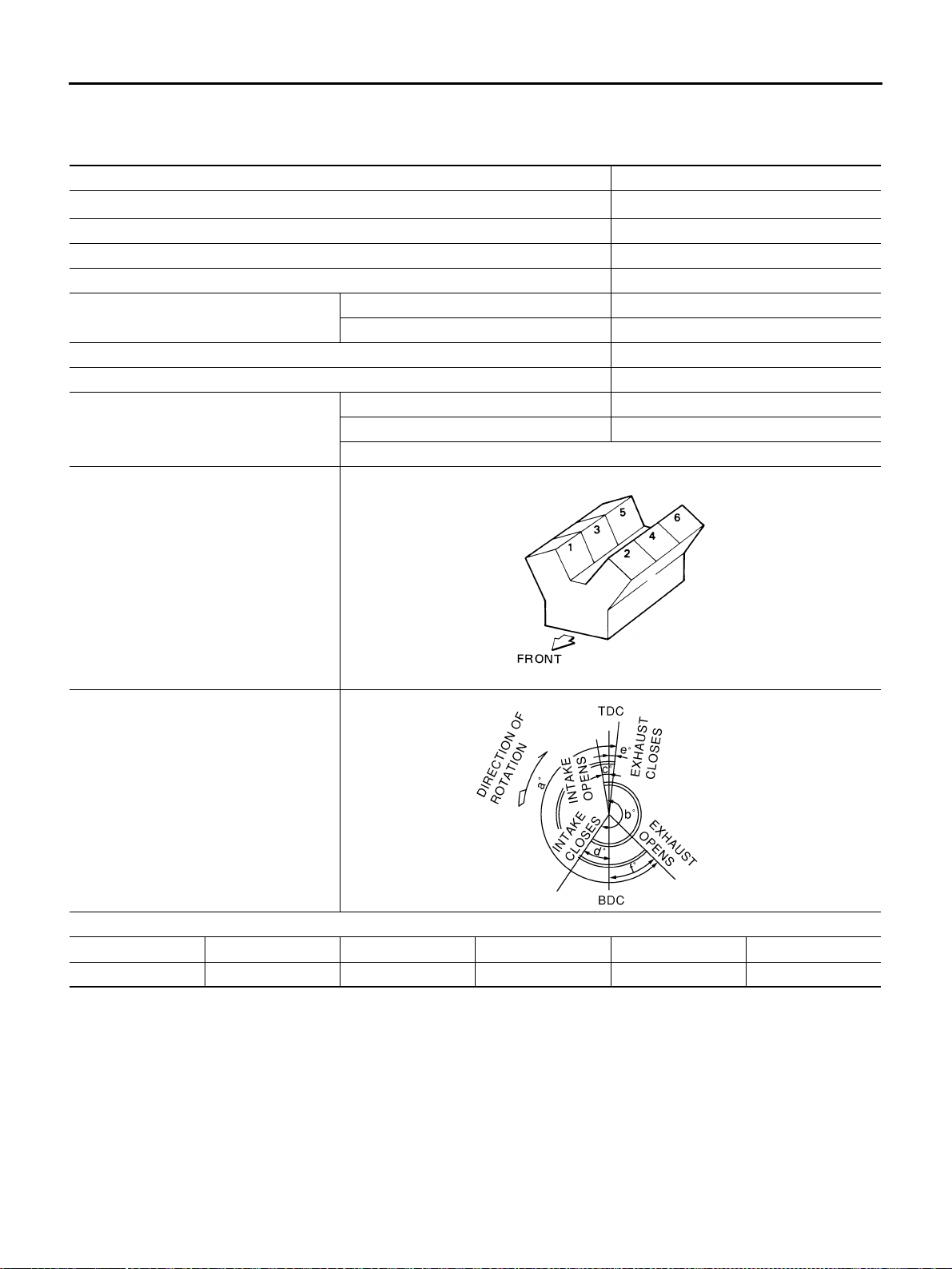
EM-146
[VQ35DE]
SERVICE DATA AND SPECIFICATIONS (SDS)
Revision: 2004 November 2004 FX35/FX45
SERVICE DATA AND SPECIFICATIONS (SDS) PFP:00100
Standard and Limit ABS004XK
GENERAL SPECIFICATIONS
Cylinder arrangement V-6
Displacement cm
3
(cu in)
3,498 (213.45)
Bore and stroke mm (in) 95.5 x 81.4 (3.76 x 3.205)
Valve arrangement DOHC
Firing order 1-2-3-4-5-6
Number of piston rings
Compression 2
Oil 1
Number of main bearings 4
Compression ratio 10.3
Compression pressure
kPa (kg/cm
2
, psi)/300 rpm
Standard 1,275 (13.0, 185)
Minimum 981 (10.0, 142)
Differential limit between cylinders 98 (1.0, 14)
Cylinder number
Valve timing
(Intake valve timing control - “OFF”)
Unit: degree
abcdef
240 238 - 6 64 8 52
SEM713A
PBIC0187E
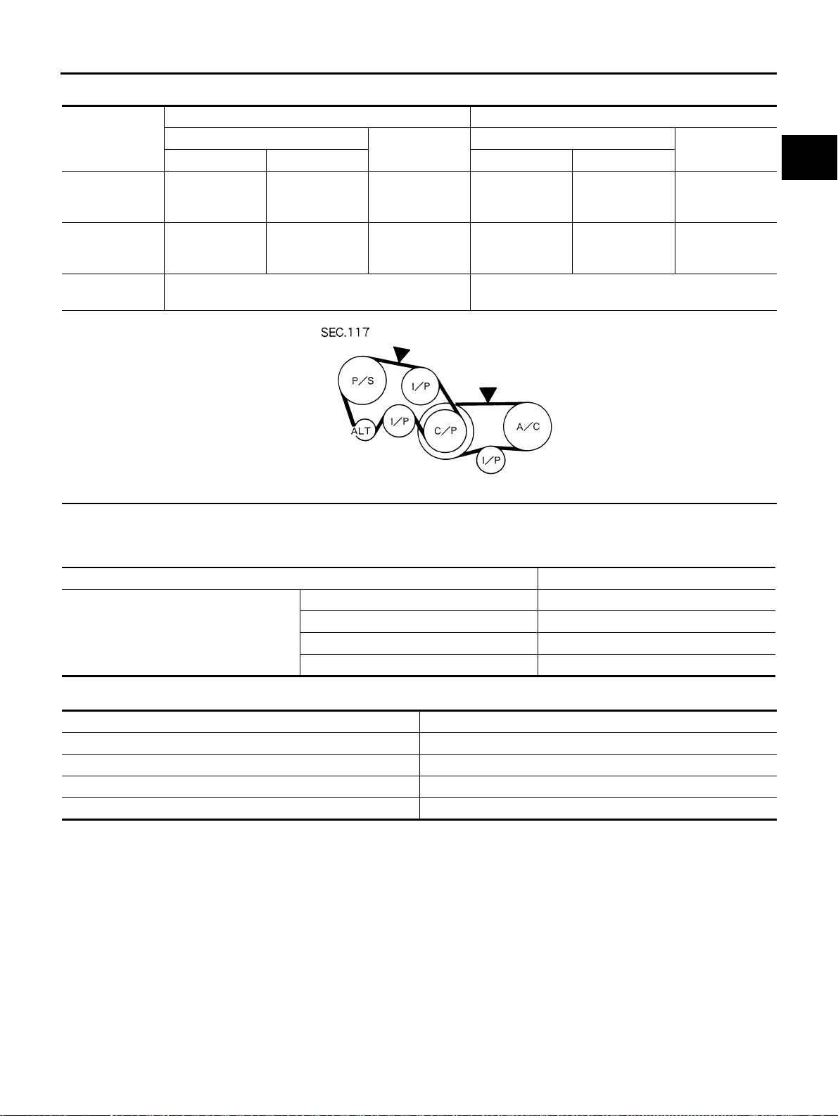
SERVICE DATA AND SPECIFICATIONS (SDS)
EM-147
[VQ35DE]
C
D
E
F
G
H
I
J
K
L
M
A
EM
Revision: 2004 November 2004 FX35/FX45
DRIVE BELT
*: If belt tension gauge cannot be installed at check points shown, check drive belt tension at different location on the belt.
INTAKE MANIFOLD COLLECTOR, INTAKE MANIFOLD AND EXHAUST MANIFOLD
Unit: mm (in)
SPARK PLUG
Items
Deflection adjustment Unit: mm (in) Tension adjustment* Unit: N (kg, lb)
Used belt
New belt
Used belt
New belt
Limit After adjustment Limit After adjustment
Alternator and
power steering
oil pump belt
7 (0.28)
4 - 5
(0.16 - 0.20)
3.5 - 4.5
(0.138 - 0.177)
294 (30, 66)
730 - 818
(74.5 - 83.5,
164 - 184)
838 - 926
(85.5 - 94.5,
188 - 208)
Air conditioner
compressor belt
12 (0.47)
9 - 10
(0.35 - 0.39)
8 - 9
(0.31- 0.35)
196 (20, 44)
348 - 436
(35.5 - 44.5,
78 - 98)
470 - 559
(48 - 57,
106 - 126)
Applied pushing
force
98 N (10 kg, 22 lb) —
KBIA1731J
Items Limit
Surface distortion
Intake manifold collector upper 0.1 (0.004)
Intake manifold collector lower 0.1 (0.004)
Intake manifold 0.1 (0.004)
Exhaust manifold 0.3 (0.012)
Make NGK
Standard type PLFR5A-11
Hot type PLFR4A-11
Cold type PLFR6A-11
Gap (nominal) 1.1 mm (0.043 in)
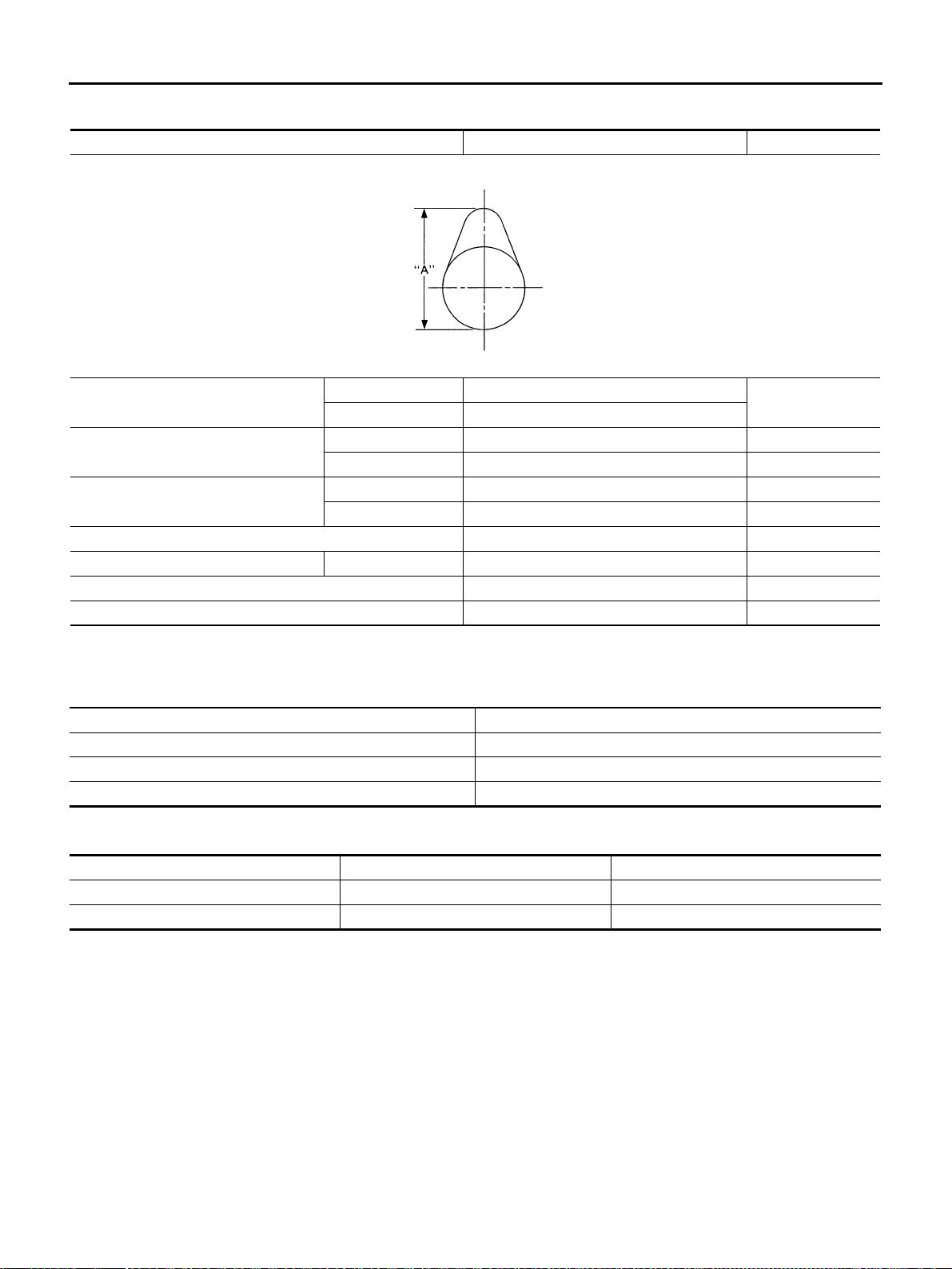
EM-148
[VQ35DE]
SERVICE DATA AND SPECIFICATIONS (SDS)
Revision: 2004 November 2004 FX35/FX45
CAMSHAFT AND CAMSHAFT BEARING
Unit: mm (in)
*: Total indicator reading
Valve Lifter
Unit: mm (in)
Valve Clearance
Unit: mm (in)
*: Approximately 80°C (176°F)
Items Standard Limit
Camshaft journal to bearing clearance
No. 1 0.045 - 0.086 (0.0018 - 0.0034)
0.15 (0.0059)
No. 2, 3, 4 0.035 - 0.076 (0.0014 - 0.0030)
Inner diameter of camshaft bearing
No. 1 26.000 - 26.021 (1.0236 - 1.0244) —
No. 2, 3, 4 23.500 - 23.521 (0.9252 - 0.9260) —
Outer diameter of camshaft journal
No. 1 25.935 - 25.955 (1.0211 - 1.0218) —
No. 2, 3, 4 23.445 - 23.465 (0.9230 - 0.9238) —
Camshaft end play 0.115 - 0.188 (0.0045 - 0.0074) 0.24 (0.0094)
Camshaft cam height “A” Intake and exhaust 44.865 - 45.055 (1.7663 - 1.7738) 0.2 (0.008)
Camshaft runout [TIR*] Less than 0.05 (0.0020) —
Camshaft sprocket runout [TIR*] — 0.15 (0.0059)
SEM671
Items Standard
Valve lifter outer diameter 33.977 - 33.987 (1.3377 - 1.3381)
Lifter guide inner diameter 34.000 - 34.016 (1.3386 - 1.3392)
Clearance between lifter and lifter guide 0.013 - 0.039 (0.0005 - 0.0015)
Items Cold Hot* (reference data)
Intake 0.26 - 0.34 (0.010 - 0.013) 0.304 - 0.416 (0.012 - 0.016)
Exhaust 0.29 - 0.37 (0.011 - 0.015) 0.308 - 0.432 (0.012 - 0.017)
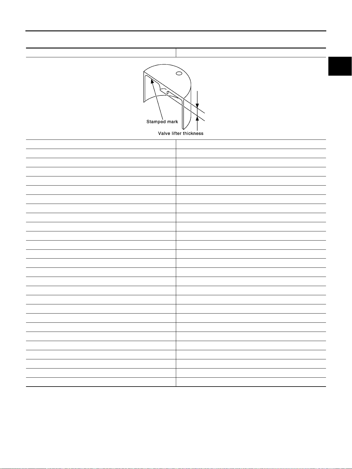
SERVICE DATA AND SPECIFICATIONS (SDS)
EM-149
[VQ35DE]
C
D
E
F
G
H
I
J
K
L
M
A
EM
Revision: 2004 November 2004 FX35/FX45
Available Valve Lifter
Unit: mm (in)
Identification (stamped) Mark Thickness
788U or 788R 7.88 (0.3102)
790U or 790R 7.90 (0.3110)
792U or 792R 7.92 (0.3118)
794U or 794R 7.94 (0.3126)
796U or 796R 7.96 (0.3134)
798U or 798R 7.98 (0.3142)
800U or 800R 8.00 (0.3150)
802U or 802R 8.02 (03.157)
804U or 804R 8.04 (0.3165)
806U or 806R 8.06 (0.3173)
808U or 808R 8.08 (0.3181)
810U or 810R 8.10 (0.3189)
812U or 812R 8.12 (0.3197)
814U or 814R 8.14 (0.3205)
816U or 816R 8.16 (0.3213)
818U or 818R 8.18 (0.3220)
820U or 820R 8.20 (0.3228)
822U or 822R 8.22 (0.3236)
824U or 824R 8.24 (0.3244)
826U or 826R 8.26 (0.3252)
828U or 828R 8.28 (0.3260)
830U or 830R 8.30 (0.3268)
832U or 832R 8.32 (0.3276)
834U or 834R 8.34 (0.3283)
836U or 836R 8.36 (0.3291)
838U or 838R 8.38 (0.3299)
840U or 840R 8.40 (0.3307)
SEM758G
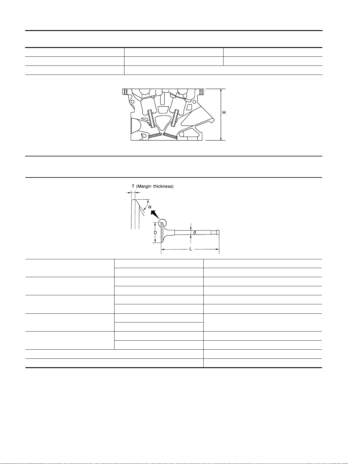
EM-150
[VQ35DE]
SERVICE DATA AND SPECIFICATIONS (SDS)
Revision: 2004 November 2004 FX35/FX45
CYLINDER HEAD
Unit: mm (in)
Valve Dimensions
Unit: mm (in)
Items Standard Limit
Head surface distortion 0.03 (0.0012) 0.1 (0.004)
Normal cylinder head height “H” 126.3 - 126.5 (4.972 - 4.980)
PBIC0924E
Valve head diameter “D” Intake 37.0 - 37.3 (1.4567 - 1.4685)
Exhaust 31.2 - 31.5 (1.228 - 1.240)
Valve length “L”
Intake 96.37 (3.7941)
Exhaust 93.90 (3.6968)
Valve stem diameter “d”
Intake 5.965 - 5.980 (0.2348 - 0.2354)
Exhaust 5.955 - 5.970 (0.2344 - 0.2350)
Valve seat angle “α”
Intake
45°15′ - 45°45′
Exhaust
Valve margin “T”
Intake 1.1 (0.043)
Exhaust 1.3 (0.051)
Valve margin “T” limit More than 0.5 (0.020)
Valve stem end surface grinding limit Less than 0.2 (0.008)
SEM188
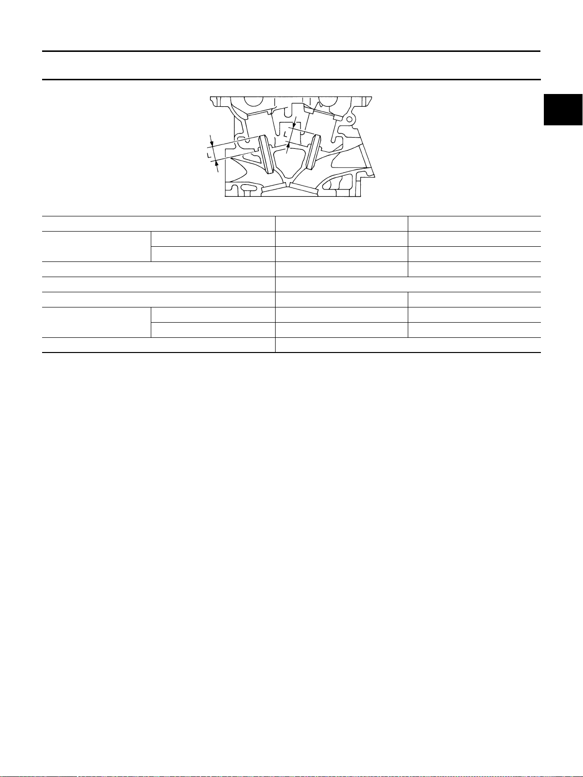
SERVICE DATA AND SPECIFICATIONS (SDS)
EM-151
[VQ35DE]
C
D
E
F
G
H
I
J
K
L
M
A
EM
Revision: 2004 November 2004 FX35/FX45
Valve Guide
Unit: mm (in)
Items Standard 0.2 (0.008) Oversize (Service)
Valve guide
Outer diameter 10.023 - 10.034 (0.3946 - 0.3950) 10.223 - 10.234 (0.4025 - 0.4029)
Inner diameter (Finished size) 6.000 - 6.018 (0.2362 - 0.2369) —
Cylinder head valve guide hole diameter 9.975 - 9.996 (0.3927 - 0.3935) 10.175 - 10.196 (0.4006 - 0.4014)
Interference fit of valve guide 0.027 - 0.059 (0.0011 - 0.0023)
Items Standard Limit
Stem to guide clearance
Intake 0.020 - 0.053 (0.0008 - 0.0021) 0.08 (0.0031)
Exhaust 0.030 - 0.063 (0.0012 - 0.0025) 0.09 (0.0035)
Projection length “L” 12.6 - 12.8 (0.496 - 0.504)
SEM950E
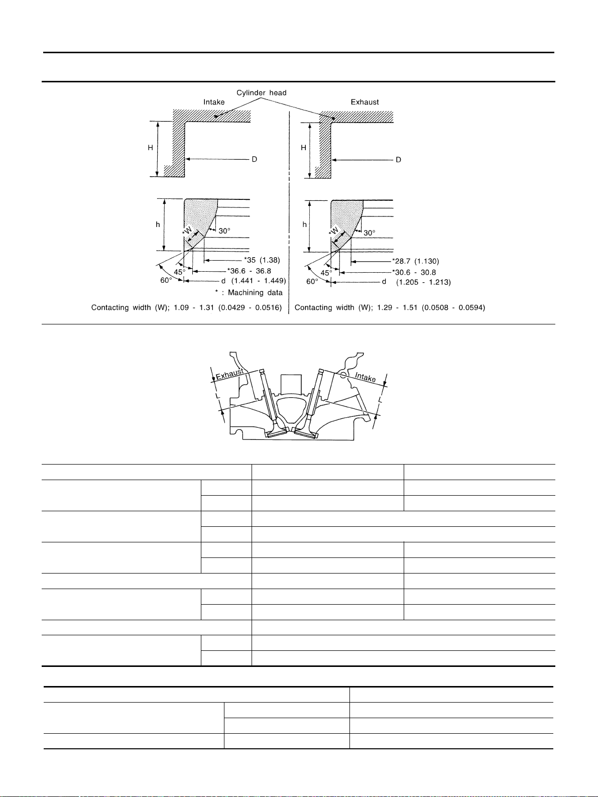
EM-152
[VQ35DE]
SERVICE DATA AND SPECIFICATIONS (SDS)
Revision: 2004 November 2004 FX35/FX45
Valve Seat
Unit: mm (in)
Valve Spring
Items Standard Oversize [0.5 (0.020)] (Service)
Cylinder head seat recess diameter “D”
Intake 38.000 - 38.016 (1.4961 - 1.4967) 38.500 - 38.516 (1.5157 - 1.5164)
Exhaust 32.200 - 32.216 (1.2677 - 1.2683) 32.700 - 32.716 (1.2874 - 1.2880)
Valve seat interference fit
Intake 0.081 - 0.113 (0.0032 - 0.0044)
Exhaust 0.064 - 0.096 (0.0025 - 0.0038)
Valve seat outer diameter “d”
Intake 38.097 - 38.113 (1.4999 - 1.5005) 38.597 - 38.613 (1.5196 - 1.5202)
Exhaust 32.280 - 32.296 (1.2709 - 1.2715) 32.780 - 32.796 (1.2905 - 1.2912)
Items Standard Service
Height “h”
Intake 5.9 - 6.0 (0.232 - 0.236) 5.05 - 5.15 (0.1988 - 0.2028)
Exhaust 5.9 - 6.0 (0.232 - 0.236) 4.95 - 5.05 (0.1949 - 0.1988)
Depth “H” 5.9 - 6.1 (0.232 - 0.240)
Depth “L”
Intake 41.07 - 41.67 (1.6169 - 1.6405)
Exhaust 41.00 - 41.60 (1.6142 - 1.6378)
SEM021EB
SEM621F
Free height mm (in) 47.07 (1.8531)
Pressure N (kg, lb) at height mm (in)
Installation 166 - 188 (16.9 - 19.2, 37.3 - 42.3) at 37.0 (1.4567)
Valve open 373 - 421 (38.0 - 42.9, 83.9 - 94.6) at 27.2 (1.0709)
Out-of-square mm (in) Limit Less than 2.1 (0.083)
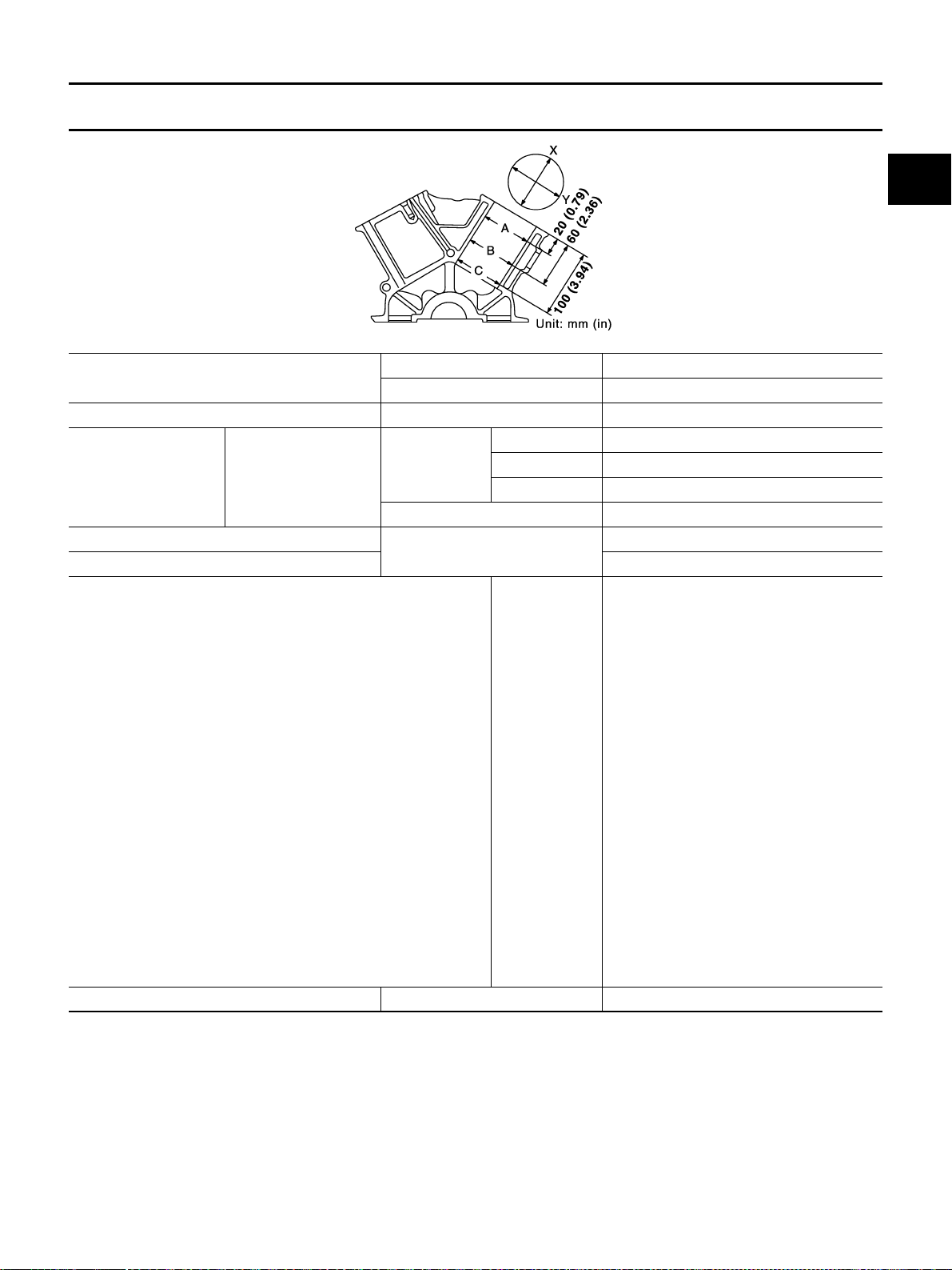
SERVICE DATA AND SPECIFICATIONS (SDS)
EM-153
[VQ35DE]
C
D
E
F
G
H
I
J
K
L
M
A
EM
Revision: 2004 November 2004 FX35/FX45
CYLINDER BLOCK
Unit: mm (in)
Surface flatness
Standard 0.03 (0.0012)
Limit 0.10 (0.0039)
Inner diameter of main bearing housing Standard 63.993 - 64.017 (2.5194 - 2.5203)
Cylinder bore Inner diameter
Standard
Grade No. 1 95.500 - 95.510 (3.7598 - 3.7602)
Grade No. 2 95.510 - 95.520 (3.7602 - 3.7606)
Grade No. 3 95.520 - 95.530 (3.7606 - 3.7610)
Wear limit 0.20 (0.0079)
Out-of-round (Difference between “X” and “Y”)
Limit
0.015 (0.0006)
Taper (Difference between “A” and “C”) 0.010 (0.0004)
Main journal inner diameter grade (Without bearing)
Grade No. A
Grade No. B
Grade No. C
Grade No. D
Grade No. E
Grade No. F
Grade No. G
Grade No. H
Grade No. J
Grade No. K
Grade No. L
Grade No. M
Grade No. N
Grade No. P
Grade No. R
Grade No. S
Grade No. T
Grade No. U
Grade No. V
Grade No. W
Grade No. X
Grade No. Y
Grade No. 4
Grade No. 7
63.993 - 63.994 (2.5194 - 2.5194)
63.994 - 63.995 (2.5194 - 2.5195)
63.995 - 63.996 (2.5195 - 2.5195)
63.996 - 63.997 (2.5195 - 2.5196)
63.997 - 63.998 (2.5196 - 2.5196)
63.998 - 63.999 (2.5196 - 2.5196)
63.999 - 64.000 (2.5196 - 2.5197)
64.000 - 64.001 (2.5197 - 2.5197)
64.001 - 64.002 (2.5197 - 2.5198)
64.002 - 64.003 (2.5198 - 2.5198)
64.003 - 64.004 (2.5198 - 2.5198)
64.004 - 64.005 (2.5198 - 2.5199)
64.005 - 64.006 (2.5199 - 2.5199)
64.006 - 64.007 (2.5199 - 2.5200)
64.007 - 64.008 (2.5200 - 2.5200)
64.008 - 64.009 (2.5200 - 2.5200)
64.009 - 64.010 (2.5200 - 2.5201)
64.010 - 64.011 (2.5201 - 2.5201)
64.011 - 64.012 (2.5201 - 2.5202)
64.012 - 64.013 (2.5202 - 2.5202)
64.013 - 64.014 (2.5202 - 2.5202)
64.014 - 64.015 (2.5202 - 2.5203)
64.015 - 64.016 (2.5203 - 2.5203)
64.016 - 64.017 (2.5203 - 2.5203)
Difference in inner diameter between cylinders Standard Less than 0.03 (0.0012)
PBIC0923E
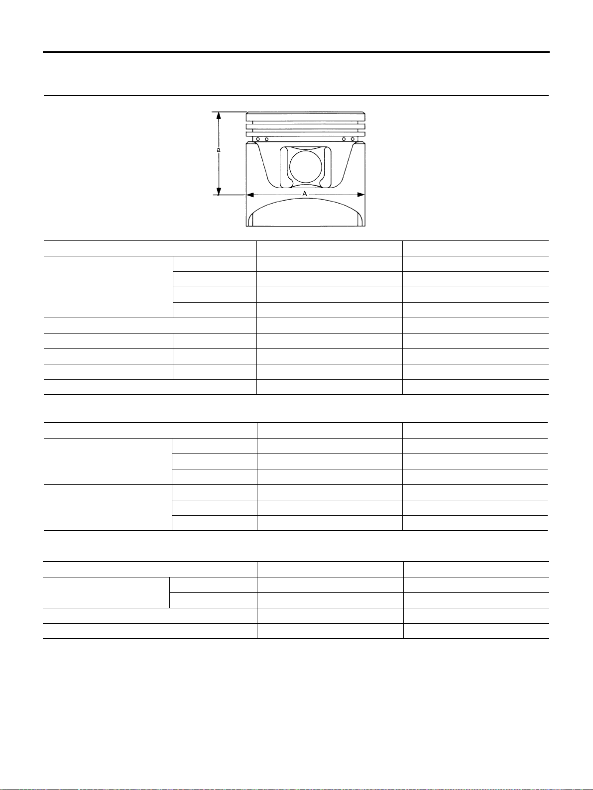
EM-154
[VQ35DE]
SERVICE DATA AND SPECIFICATIONS (SDS)
Revision: 2004 November 2004 FX35/FX45
PISTON, PISTON RING AND PISTON PIN
Available Piston
Unit: mm (in)
Piston Ring
Unit: mm (in)
Piston Pin
Unit: mm (in)
Items Standard 0.20 (0.0079) oversize
Piston skirt diameter “A”
Grade No. 1 95.480 - 95.490 (3.7590 - 3.7594) —
Grade No. 2 95.490 - 95.500 (3.7594 - 3.7598) —
Grade No. 3 95.500 - 95.510 (3.7598 - 3.7602) —
Service — 95.680 - 95.710 (3.7669 - 3.7681)
Items Standard Limit
“a” dimension 41.0 (1.614) —
Piston pin hole diameter Grade No. 0 21.993 - 21.999 (0.8659 - 0.8661) —
Grade No. 1 21.999 - 22.005 (0.8661 - 0.8663) —
Piston to cylinder bore clearance 0.010 - 0.030 (0.0004 - 0.0012) 0.08 (0.0031)
SEM882E
Items Standard Limit
Side clearance
Top 0.045 - 0.080 (0.0018 - 0.0031) 0.11 (0.0043)
2nd 0.030 - 0.070 (0.0012 - 0.0028) 0.1 (0.004)
Oil ring 0.065 - 0.135 (0.0026 - 0.0053) —
End gap
Top 0.23 - 0.33 (0.0091 - 0.0130) 0.54 (0.0213)
2nd 0.33 - 0.48 (0.0130 - 0.0189) 0.80 (0.0315)
Oil (rail ring) 0.20 - 0.50 (0.0079 - 0.0197) 0.95 (0.0374)
Items Standard Limit
Piston pin outer diameter
Grade No. 0 21.989 - 21.995 (0.8657 - 0.8659) —
Grade No. 1 21.995 - 22.001 (0.8659 - 0.8662) —
Interference fit of piston pin to piston 0.002 - 0.006 (0.0001 - 0.0002) —
Piston pin to connecting rod bushing oil clearance 0.005 - 0.017 (0.0002 - 0.0007) 0.030 (0.0012)

SERVICE DATA AND SPECIFICATIONS (SDS)
EM-155
[VQ35DE]
C
D
E
F
G
H
I
J
K
L
M
A
EM
Revision: 2004 November 2004 FX35/FX45
CONNECTING ROD
Unit: mm (in)
*: After installing in connecting rod
Items Standard Limit
Center distance 144.15 - 144.25 (5.6752 - 5.6791) —
Bend [per 100 (3.94)] — 0.15 (0.0059)
Torsion [per 100 (3.94)] — 0.30 (0.0118)
Connecting rod bushing inner diameter*
Grade No. 0 22.000 - 22.006 (0.8661 - 0.8664) —
Grade No. 1 22.006 - 22.012 (0.8664 - 0.8666) —
Connecting rod big end inner diameter (Without bearing) 55.000 - 55.013 (2.1654 - 2.1659) —
Side clearance 0.20 - 0.35 (0.0079 - 0.0138) 0.40 (0.0157)
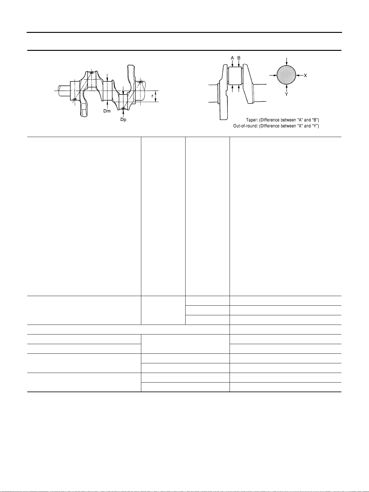
EM-156
[VQ35DE]
SERVICE DATA AND SPECIFICATIONS (SDS)
Revision: 2004 November 2004 FX35/FX45
CRANKSHAFT
Unit: mm (in)
*: Total indicator reading
Main journal dia. “Dm” grade Standard
Grade No. A
Grade No. B
Grade No. C
Grade No. D
Grade No. E
Grade No. F
Grade No. G
Grade No. H
Grade No. J
Grade No. K
Grade No. L
Grade No. M
Grade No. N
Grade No. P
Grade No. R
Grade No. S
Grade No. T
Grade No. U
Grade No. V
Grade No. W
Grade No. X
Grade No. Y
Grade No. 4
Grade No. 7
59.975 - 59.974 (2.3612 - 2.3612)
59.974 - 59.973 (2.3612 - 2.3611)
59.973 - 59.972 (2.3611 - 2.3611)
59.972 - 59.971 (2.3611 - 2.3611)
59.971 - 59.970 (2.3611 - 2.3610)
59.970 - 59.969 (2.3610 - 2.3610)
59.969 - 59.968 (2.3610 - 2.3609)
59.968 - 59.967 (2.3609 - 2.3609)
59.967 - 59.966 (2.3609 - 2.3609)
59.966 - 59.965 (2.3609 - 2.3608)
59.965 - 59.964 (2.3608 - 2.3608)
59.964 - 59.963 (2.3608 - 2.3607)
59.963 - 59.962 (2.3607 - 2.3607)
59.962 - 59.961 (2.3607 - 2.3607)
59.961 - 59.960 (2.3607 - 2.3606)
59.960 - 59.959 (2.3606 - 2.3606)
59.959 - 59.958 (2.3606 - 2.3605)
59.958 - 59.957 (2.3605 - 2.3605)
59.957 - 59.956 (2.3605 - 2.3605)
59.956 - 59.955 (2.3605 - 2.3604)
59.955 - 59.954 (2.3604 - 2.3604)
59.954 - 59.953 (2.3604 - 2.3603)
59.953 - 59.952 (2.3603 - 2.3603)
59.952 - 59.951 (2.3603 - 2.3603)
Pin journal dia. “Dp” Standard
Grade No. 0 51.968 - 51.974 (2.0460 - 2.0462)
Grade No. 1 51.962 - 51.968 (2.0457 - 2.0460)
Grade No. 2 51.956 - 51.962 (2.0445 - 2.0457)
Center distance “r” 40.36 - 40.44 (1.5890 - 1.5921)
Taper (Difference between “A” and “B”)
Standard
Less than 0.002 (0.0001)
Out-of-round (Difference between “X” and “Y”) Less than 0.002 (0.0001)
Crankshaft runout [TIR*]
Standard Less than 0.025 (0.0010)
Limit Less than 0.10 (0.0039)
Crankshaft end play
Standard 0.10 - 0.25 (0.0039 - 0.0098)
Limit 0.30 (0.0118)
SEM645 SBIA0535E
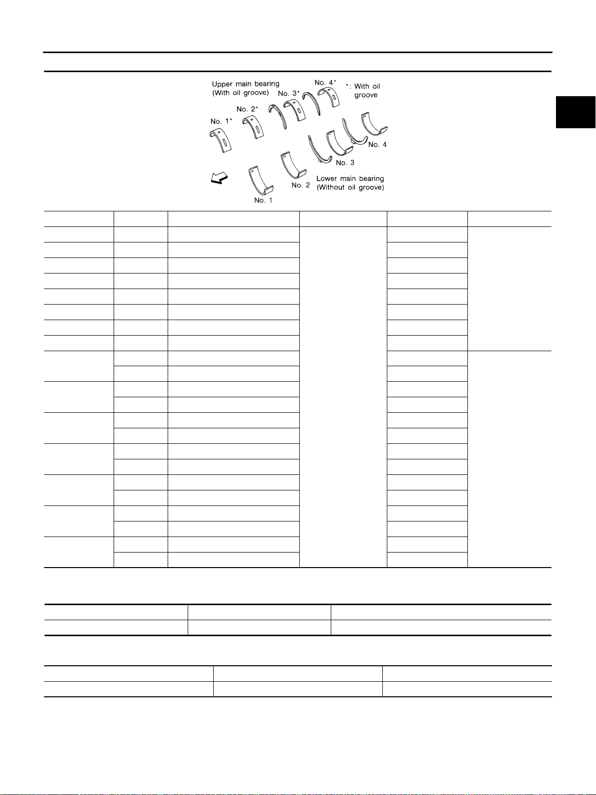
SERVICE DATA AND SPECIFICATIONS (SDS)
EM-157
[VQ35DE]
C
D
E
F
G
H
I
J
K
L
M
A
EM
Revision: 2004 November 2004 FX35/FX45
MAIN BEARING
Undersize
Unit: mm (in)
Main Bearing Oil Clearance
Unit: mm (in)
*: Actual clearance
Grade number UPR/LWR Thickness “T” mm (in) Width “W” mm (in) Identification color Remarks
0 — 2.000 - 2.003 (0.0787 - 0.0789)
19.9 - 20.1
(0.783 - 0.791)
Black
Grade is the same
for upper and lower
bearings.
1 — 2.003 - 2.006 (0.0789 - 0.0790) Brown
2 — 2.006 - 2.009 (0.0790 - 0.0791) Green
3 — 2.009 - 2.012 (0.0791 - 0.0792) Yellow
4 — 2.012 - 2.015 (0.0792 - 0.0793) Blue
5 — 2.015 - 2.018 (0.0793 - 0.0794) Pink
6 — 2.018 - 2.021 (0.0794 - 0.0796) Purple
7 — 2.021 - 2.024 (0.0796 - 0.0797) White
01
UPP 2.003 - 2.006 (0.0789 - 0.0790) Brown
Grade is different
for upper and lower
bearings.
LWR 2.000 - 2.003 (0.0787 - 0.0789) Black
12
UPR 2.006 - 2.009 (0.0790 - 0.0791) Green
LWR 2.003 - 2.006 (0.0789 - 0.0790) Brown
23
UPR 2.009 - 2.012 (0.0791 - 0.0792) Yellow
LWR 2.006 - 2.009 (0.0790 - 0.0791) Green
34
UPR 2.012 - 2.015 (0.0792 - 0.0793) Blue
LWR 2.009 - 2.012 (0.0791 - 0.0792) Yellow
45
UPR 2.015 - 2.018 (0.0793 - 0.0794) Pink
LWR 2.012 - 2.015 (0.0792 - 0.0793) Blue
56
UPR 2.018 - 2.021 (0.0794 - 0.0796) Purple
LWR 2.015 - 2.018 (0.0793 - 0.0794) Pink
67
UPR 2.021 - 2.024 (0.0796 - 0.0797) White
LWR 2.018 - 2.021 (0.0794 - 0.0796) Purple
SEM175F
Items Thickness Main journal diameter “Dm”
0.25 (0.0098) 2.132 - 2.140 (0.0839 - 0.0843) Grind so that bearing clearance is the specified value.
Items Standard Limit
Main bearing oil clearance 0.035 - 0.045 (0.0014 - 0.0018)* 0.065 (0.0026)
EM-158
[VQ35DE]
SERVICE DATA AND SPECIFICATIONS (SDS)
Revision: 2004 November 2004 FX35/FX45
CONNECTING ROD BEARING
Undersize
Unit: mm (in)
Connecting Rod Bearing Oil Clearance
Unit: mm (in)
*: Actual clearance
Grade number Thickness “T” mm (in) Identification color (mark)
0 1.500 - 1.503 (0.0591 - 0.0592) Black
1 1.503 - 1.506 (0.0592 - 0.0593) Brown
2 1.506 - 1.509 (0.0593 - 0.0594) Green
Items Thickness Crank pin journal diameter “Dp”
0.25 (0.0098) 1.626 - 1.634 (0.0640 - 0.0643) Grind so that bearing clearance is the specified value.
Items Standard Limit
Connecting rod bearing oil clearance 0.034 - 0.059 (0.0013 - 0.0023)* 0.070 (0.0028)

PRECAUTIONS
EM-159
[VK45DE]
C
D
E
F
G
H
I
J
K
L
M
A
EM
Revision: 2004 November 2004 FX35/FX45
[VK45DE]
PRECAUTIONS PFP:00001
Precautions Necessary for Steering Wheel Rotation After Battery Disconnect
ABS00DAO
NOTE:
● This Procedure is applied only to models with Intelligent Key system and NVIS/IVIS (NISSAN/INFINITI
VEHICLE IMMOBILIZER SYSTEM - NATS).
● Remove and install all control units after disconnecting both battery cables with the ignition knob in the
″LOCK″ position.
● Always use CONSULT-II to perform self-diagnosis as a part of each function inspection after finishing
work. If DTC is detected, perform trouble diagnosis according to self-diagnostic results.
For models equipped with the Intelligent Key system and NVIS/IVIS, an electrically controlled steering lock
mechanism is adopted on the key cylinder.
For this reason, if the battery is disconnected or if the battery is discharged, the steering wheel will lock and
steering wheel rotation will become impossible.
If steering wheel rotation is required when battery power is interrupted, follow the procedure below before
starting the repair operation.
OPERATION PROCEDURE
1. Connect both battery cables.
NOTE:
Supply power using jumper cables if battery is discharged.
2. Use the Intelligent Key or mechanical key to turn the ignition switch to the ″ACC″ position. At this time, the
steering lock will be released.
3. Disconnect both battery cables. The steering lock will remain released and the steering wheel can be
rotated.
4. Perform the necessary repair operation.
5. When the repair work is completed, return the ignition switch to the ″LOCK″ position before connecting
the battery cables. (At this time, the steering lock mechanism will engage.)
6. Perform a self-diagnosis check of all control units using CONSULT-II.
Precautions for Drain Engine Coolant ABS006HV
Drain engine coolant when engine is cooled.
Precautions for Disconnecting Fuel Piping ABS006HW
● Before starting work, make sure no fire or spark producing items are in the work area.
● Release fuel pressure before disconnecting and disassembly.
● After disconnecting pipes, plug openings to stop fuel leakage.
Precautions for Removal and Disassembly ABS006HX
● When instructed to use special service tools, use specified tools. Always be careful to work safely, avoid
forceful or uninstructed operations.
● Exercise maximum care to avoid damage to mating or sliding surfaces.
● Cover openings of engine system with tape or the equivalent, if necessary, to seal out foreign materials.
● Mark and arrange disassembly parts in an organized way for easy troubleshooting and assembly.
● When loosening nuts and bolts, as a basic rule, start with the one furthest outside, then the one diagonally
opposite, and so on. If the order of loosening is specified, do exactly as specified. Power tools may be
used where noted in the step.
Precautions for Inspection, Repair and Replacement ABS006HY
Before repairing or replacing, thoroughly inspect parts. Inspect new replacement parts in the same way, and
replace if necessary.
Precautions for Assembly and Installation ABS006HZ
● Use torque wrench to tighten bolts or nuts to specification.
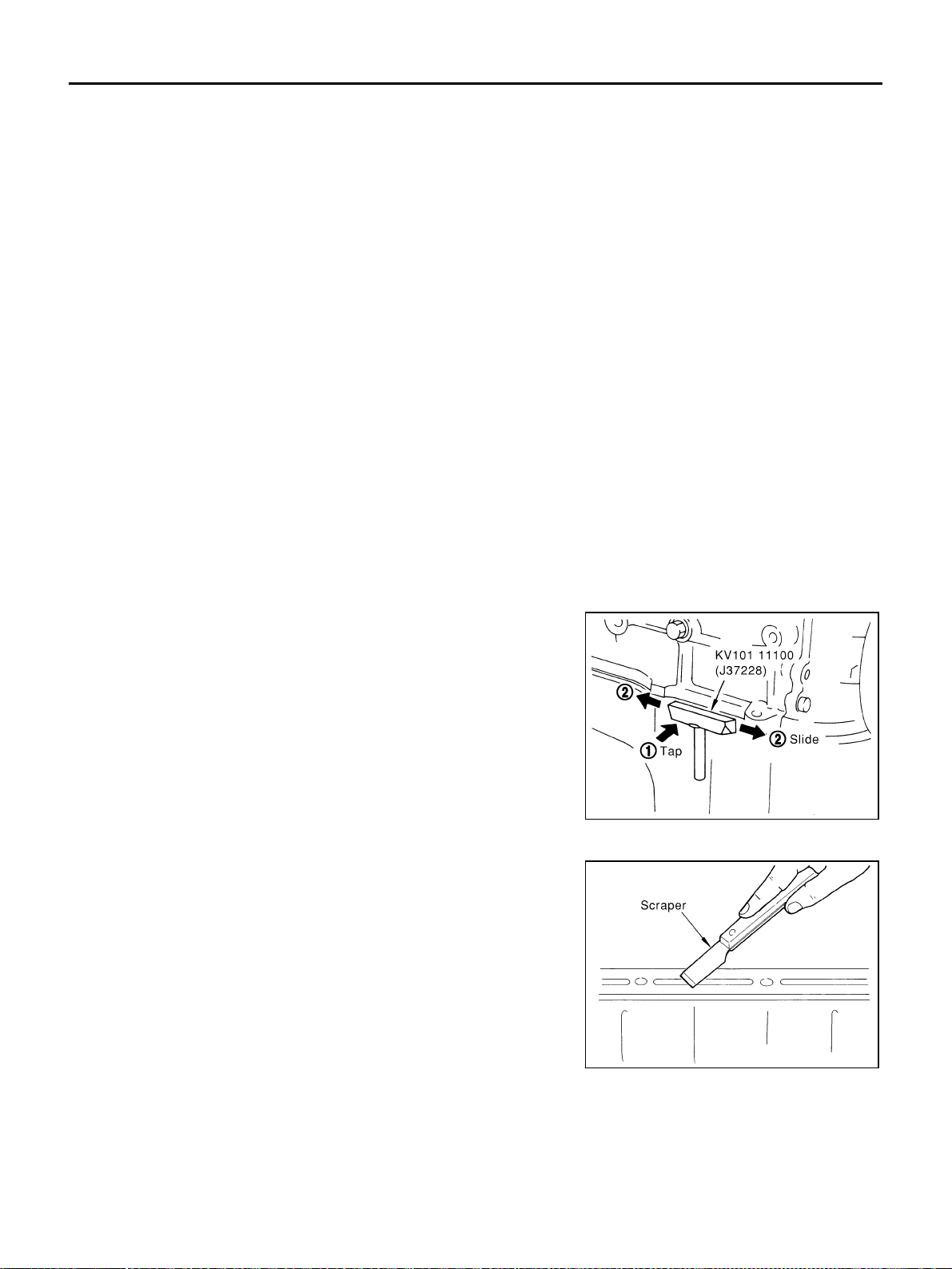
EM-160
[VK45DE]
PRECAUTIONS
Revision: 2004 November 2004 FX35/FX45
● When tightening nuts and bolts, as a basic rule, equally tighten in several different steps starting with the
ones in center, then ones on inside and outside diagonally in this order. If the order of tightening is speci-
fied, do exactly as specified.
● Replace with new gasket, packing, oil seal or O-ring.
● Thoroughly wash, clean, and air-blow each part. Carefully check engine oil or engine coolant passages for
any restriction and blockage.
● Avoid damaging sliding or mating surfaces. Completely remove foreign materials such as cloth lint or dust.
Before assembly, oil sliding surfaces well.
● Release air within route when refilling after draining engine coolant.
● After repairing, start engine and increase engine speed to check engine coolant, fuel, oil, and exhaust
systems for leakage.
Parts Requiring Angle Tightening ABS006I0
● Use angle wrench [SST: KV10112100 (BT8653-A)] for the final tightening of the following engine parts:
– Cylinder head bolts
– Main bearing cap bolts
– Connecting rod cap nuts
– Crankshaft pulley bolt (No angle wrench is required as the bolt flange is provided with notches for angle
tightening)
● Do not use a torque value for final tightening.
● The torque value for these parts are for a preliminary step.
● Ensure thread and seat surfaces are clean and coated with engine oil.
Precautions for Liquid Gasket ABS006I1
REMOVAL OF LIQUID GASKET SEALING
● After removing mounting bolts and nuts, separate the mating
surface using seal cutter (SST) and remove old liquid gasket
sealing.
CAUTION:
Be careful not to damage the mating surfaces.
● In areas where seal cutter (SST) is difficult to use, use plastic
hammer to lightly tap the areas where liquid gasket is applied.
CAUTION:
If for some unavoidable reason tool such as a flat-blade
screwdriver is used, be careful not to damage the mating
surfaces.
LIQUID GASKET APPLICATION PROCEDURE
1. Using scraper, remove old liquid gasket adhering to the liquid
gasket application surface and the mating surface.
● Remove liquid gasket completely from the groove of the liquid
gasket application surface, mounting bolts, and bolt holes.
2. Wipe the liquid gasket application surface and the mating sur-
face with white gasoline (lighting and heating use) to remove
adhering moisture, grease and foreign materials.
PBIC0002E
PBIC0003E
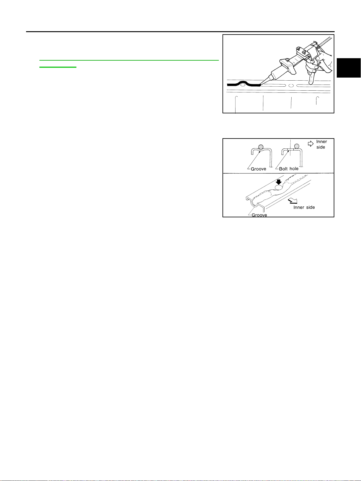
PRECAUTIONS
EM-161
[VK45DE]
C
D
E
F
G
H
I
J
K
L
M
A
EM
Revision: 2004 November 2004 FX35/FX45
3. Attach liquid gasket tube to tube presser [SST: WS39930000
(—)].
Use Genuine RTV Silicone Sealant or equivalent. Refer to
GI-48, "
RECOMMENDED CHEMICAL PRODUCTS AND
SEALANTS" .
4. Apply liquid gasket without breaks to the specified location with the specified dimensions.
● If there is a groove for the liquid gasket application, apply liquid gasket to the groove.
● As for the bolt holes, normally apply liquid gasket inside the
holes. Occasionally, it should be applied outside the holes.
Make sure to read the text of this manual.
● Within five minutes of liquid gasket application, install the mat-
ing component.
● If liquid gasket protrudes, wipe it off immediately.
● Do not retighten after the installation.
● Wait 30 minutes or more after installation before refilling
engine with engine oil and engine coolant.
CAUTION:
If there are specific instructions in this manual, observe
them.
EMA0622D
SEM159F
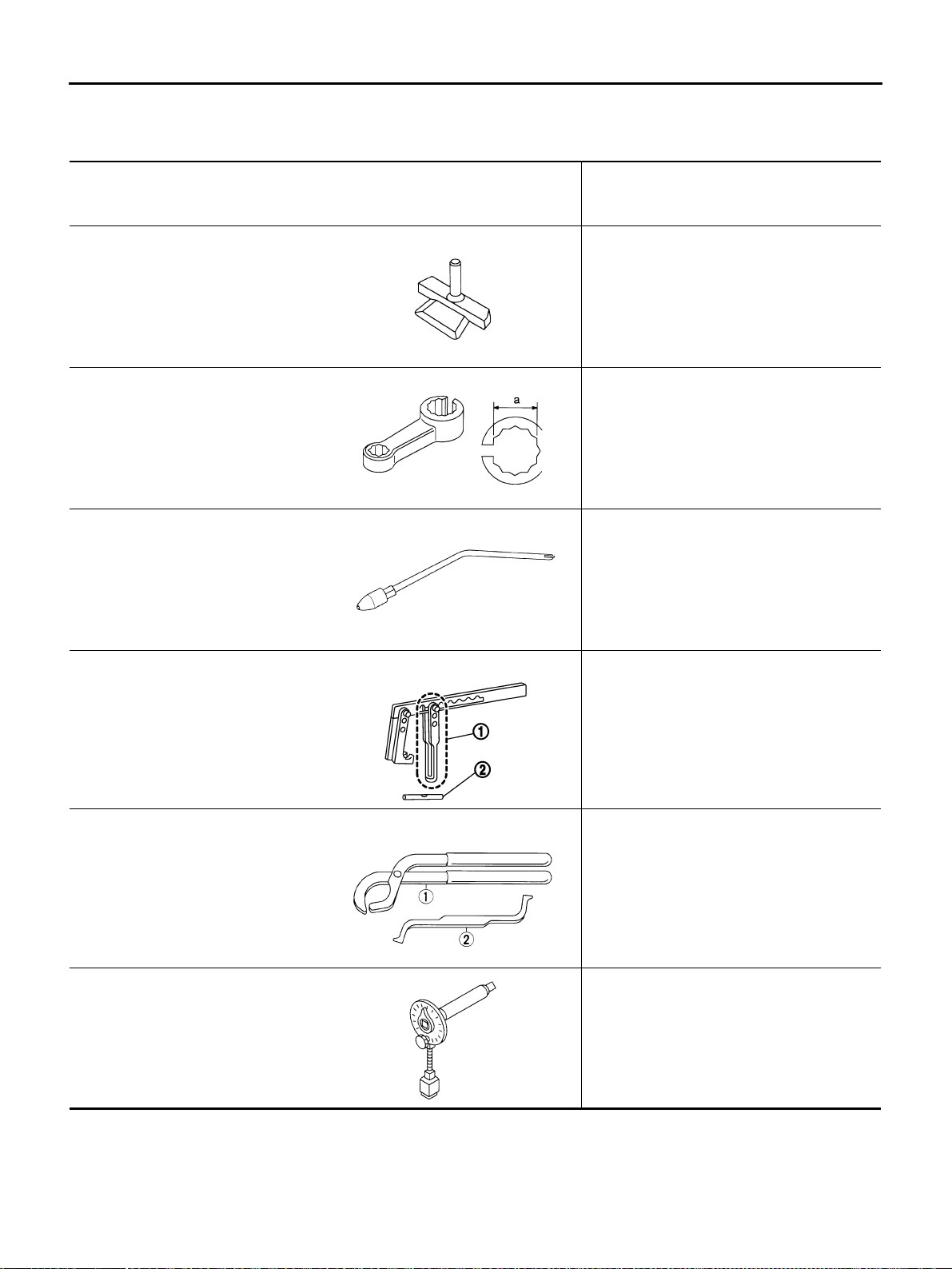
EM-162
[VK45DE]
PREPARATION
Revision: 2004 November 2004 FX35/FX45
PREPARATION PFP:00002
Special Service Tools ABS006I2
The actual shapes of Kent-Moore tools may differ from those of special service tools illustrated here.
Tool number
(Kent-Moore No.)
Tool name
Description
KV10111100
(J37228)
Seal cutter
Removing steel oil pan and front cover
KV10114400
(J-38365)
Heated oxygen sensor wrench
Loosening or tightening heated oxygen
sensors
a: 22 mm (0.87 in)
EG15050500
(J45402)
Compression gauge adapter
Inspection of compression pressure
KV10116200
(J26336-A)
Valve spring compressor
1. KV10115900
(J26336-20)
Attachment
2. KV10109220
(—)
Adapter
Disassembling valve mechanism
Part (1) is a component of KV10116200
(J26336-A), but part (2) is not so.
KV101151S0
(J38972)
Lifter stopper set
1. KV10115110
(J38972-1)
Camshaft pliers
2. KV10115120
(J38972-2)
Lifter stopper
Changing valve lifter shims
KV10112100
(BT8653-A)
Angle wrench
Tightening bolts for bearing cap, cylinder
head, etc.
S-NT046
S-NT636
ZZA1225D
PBIC1650E
S-NT041
S-NT014

PREPARATION
EM-163
[VK45DE]
C
D
E
F
G
H
I
J
K
L
M
A
EM
Revision: 2004 November 2004 FX35/FX45
KV10114700
(J38139)
Main bearing cap remover
Removing crankshaft main bearing cap
KV10107902
(J38959)
Valve oil seal puller
Removing valve oil seal
KV10115600
(J38958)
Valve oil seal drift
Installing valve oil seal
Use side A.
a: 20 (0.79) dia. d: 8 (0.31) dia.
b: 13 (0.51) dia. e: 10.7 (0.421)
c: 10.3 (0.406) dia. f: 5 (0.20)
Unit: mm (in)
EM03470000
(J8037)
Piston ring compressor
Installing piston assembly into cylinder bore
ST16610001
(J23907)
Pilot bushing puller
Removing crankshaft pilot converter
WS39930000
(—)
Tube presser
Pressing the tube of liquid gasket
Tool number
(Kent-Moore No.)
Tool name
Description
ZZA0023D
S-NT011
S-NT603
S-NT044
S-NT045
S-NT052
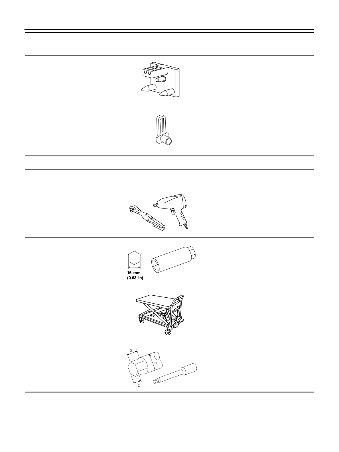
EM-164
[VK45DE]
PREPARATION
Revision: 2004 November 2004 FX35/FX45
Commercial Service Tools ABS006I3
—
(J-45476)
Ring gear stopper
Removing and installing crankshaft pulley
—
(J-45488)
Quick connector release
Removing fuel tube quick connectors in
engine room
(Available in SEC. 164 of PARTS CATALOG:
Part No. 16441 6N210)
Tool number
(Kent-Moore No.)
Tool name
Description
PBIC1655E
PBIC0198E
(Kent-Moore No.)
Tool name
Description
Power tool Loosening bolts and nuts
Spark plug wrench Removing and installing spark plug
Manual lift table caddy Removing and installing engine
(J24239-01)
Cylinder head bolt wrench
Loosening and tightening cylinder head bolt,
and use with angle wrench [SST:
KV10112100 (BT8653-A)]
a: 13 (0.51) dia.
b: 12 (0.47)
c: 10 (0.39)
Unit: mm (in)
PBIC0190E
S-NT047
ZZA1210D
NT583
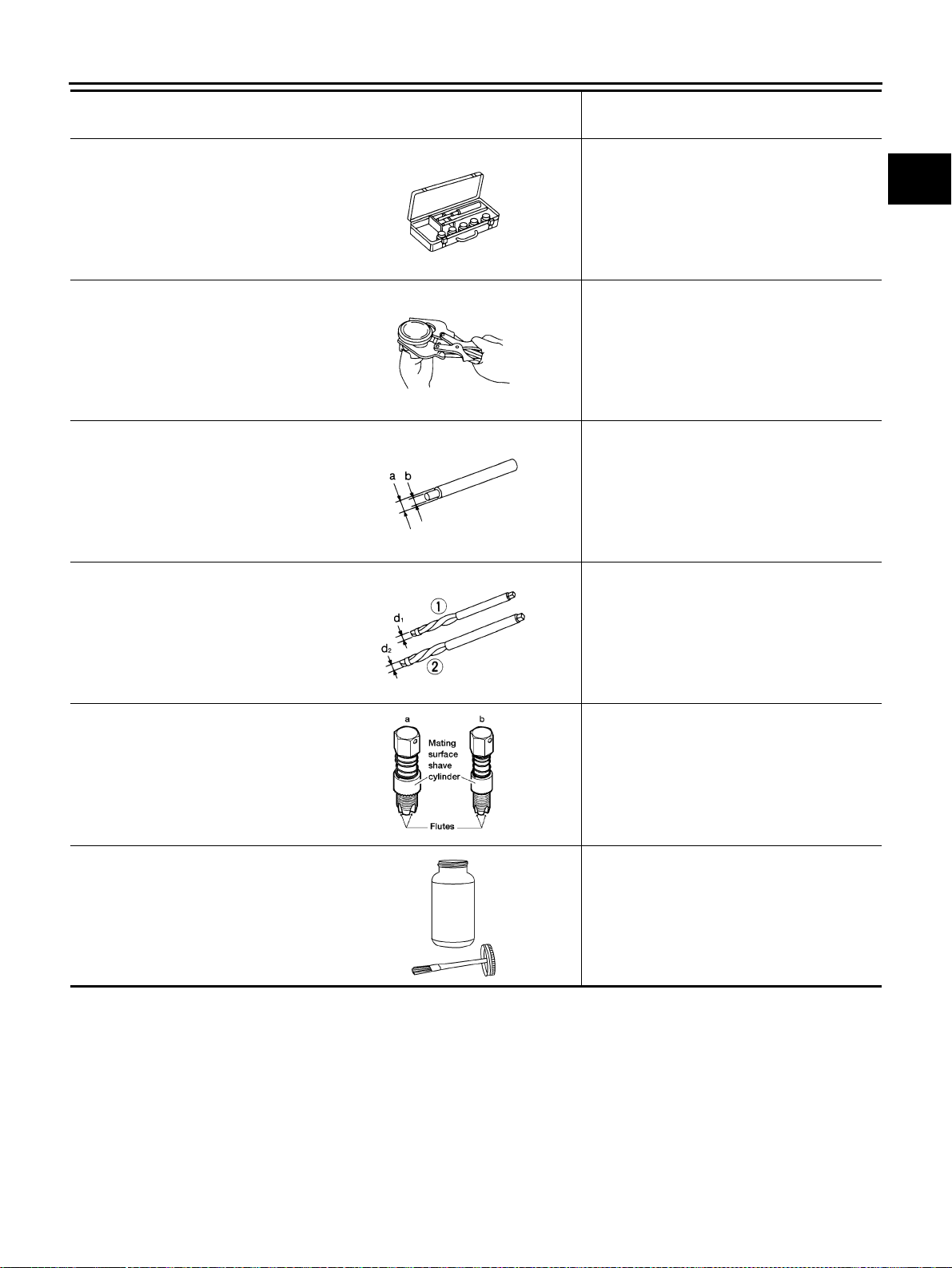
PREPARATION
EM-165
[VK45DE]
C
D
E
F
G
H
I
J
K
L
M
A
EM
Revision: 2004 November 2004 FX35/FX45
Valve seat cutter set Finishing valve seat dimensions
Piston ring expander Removing and installing piston ring
Valve guide drift Removing and installing valve guide
Intake and Exhaust:
a: 9.5 mm (0.374 in) dia.
b: 5.5 mm (0.217 in) dia.
Valve guide reamer (1): Reaming valve guide inner hole
(2): Reaming hole for oversize valve guide
Intake and Exhaust:
d
1 : 6.0 mm (0.236 in) dia.
d
2 : 10.2 mm (0.402 in) dia.
(J-43897-18)
(J-43897-12)
Oxygen sensor thread cleaner
Reconditioning the exhaust system threads
before installing a new heated oxygen
sensor (Use with anti-seize lubricant shown
below.)
a: J-43897-18 (18 mm dia.) for zirconia
heated oxygen sensor
b: J-43897-12 (12 mm dia.) for titania
heated oxygen sensor
Anti-seize lubricant (Permatex 133AR
or equivalent meeting MIL
specification MIL-A-907)
Lubricating oxygen sensor thread cleaning
tool when reconditioning exhaust system
threads
(Kent-Moore No.)
Tool name
Description
S-NT048
S-NT030
S-NT015
S-NT016
AEM488
AEM489
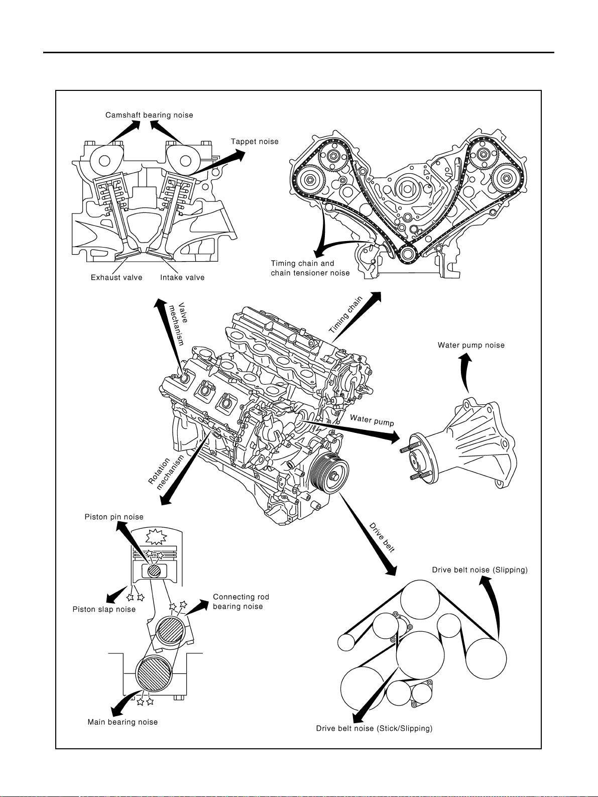
EM-166
[VK45DE]
NOISE, VIBRATION AND HARSHNESS (NVH) TROUBLESHOOTING
Revision: 2004 November 2004 FX35/FX45
NOISE, VIBRATION AND HARSHNESS (NVH) TROUBLESHOOTING PFP:00003
NVH Troubleshooting —Engine Noise ABS006I4
PBIC2330E
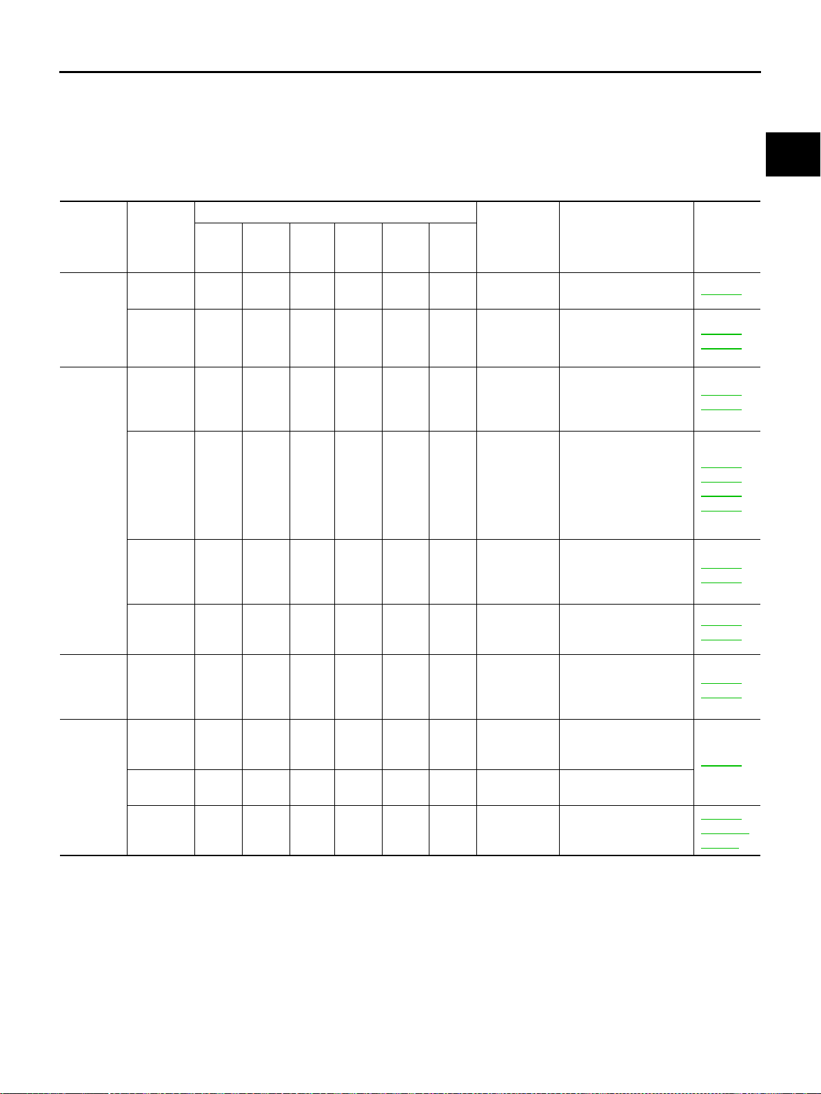
NOISE, VIBRATION AND HARSHNESS (NVH) TROUBLESHOOTING
EM-167
[VK45DE]
C
D
E
F
G
H
I
J
K
L
M
A
EM
Revision: 2004 November 2004 FX35/FX45
Use the Chart Below to Help You Find the Cause of the Symptom. ABS006I5
1. Locate the area where noise occurs.
2. Confirm the type of noise.
3. Specify the operating condition of engine.
4. Check specified noise source.
If necessary, repair or replace these parts.
A: Closely related B: Related C: Sometimes related —: Not related
Location
of noise
Type of
noise
Operating condition of engine
Source of
noise
Check item
Refer-
ence page
Before
warm-
up
After
warm-
up
When
start-
ing
When
idling
When
racing
While
driving
Top of
engine
Rocker
cover
Cylinder
head
Ticking or
clicking
C A — A B — Tappet noise Valve clearance EM-214
Rattle C A — A B C
Camshaft
bearing noise
Camshaft journal oil
clearance
Camshaft runout
EM-210
EM-209
Crank-
shaft pul-
ley
Cylinder
block
(Side of
engine)
Oil pan
Slap or
knock
—A—BB—
Piston pin
noise
Piston to piston pin oil
clearance
Connecting rod bush-
ing oil clearance
EM-256
EM-258
Slap or
rap
A——BBA
Piston slap
noise
Piston to cylinder bore
clearance
Piston ring side clear-
ance
Piston ring end gap
Connecting rod bend
and torsion
EM-260
EM-257
EM-257
EM-258
Knock ABCBBB
Connecting
rod bearing
noise
Connecting rod bush-
ing oil clearance
Connecting rod bear-
ing oil clearance
EM-258
EM-263
Knock A B — A B C
Main bearing
noise
Main bearing oil clear-
ance
Crankshaft runout
EM-264
EM-262
Front of
engine
front cover
Tapping or
ticking
AA—BBB
Timing chain
and chain
tensioner
noise
Timing chain cracks
and wear
Timing chain tensioner
operation
EM-201
EM-196
Front of
engine
Squeak-
ing or fizz-
ing
AB—B—C
Drive belts
(Sticking or
slipping)
Drive belts deflection
EM-169
Creaking A B A B A B
Drive belts
(Slipping)
Idler pulley bearing
operation
Squall
Creak
AB—BAB
Water pump
noise
Water pump operation
CO-49,
"WATER
PUMP"
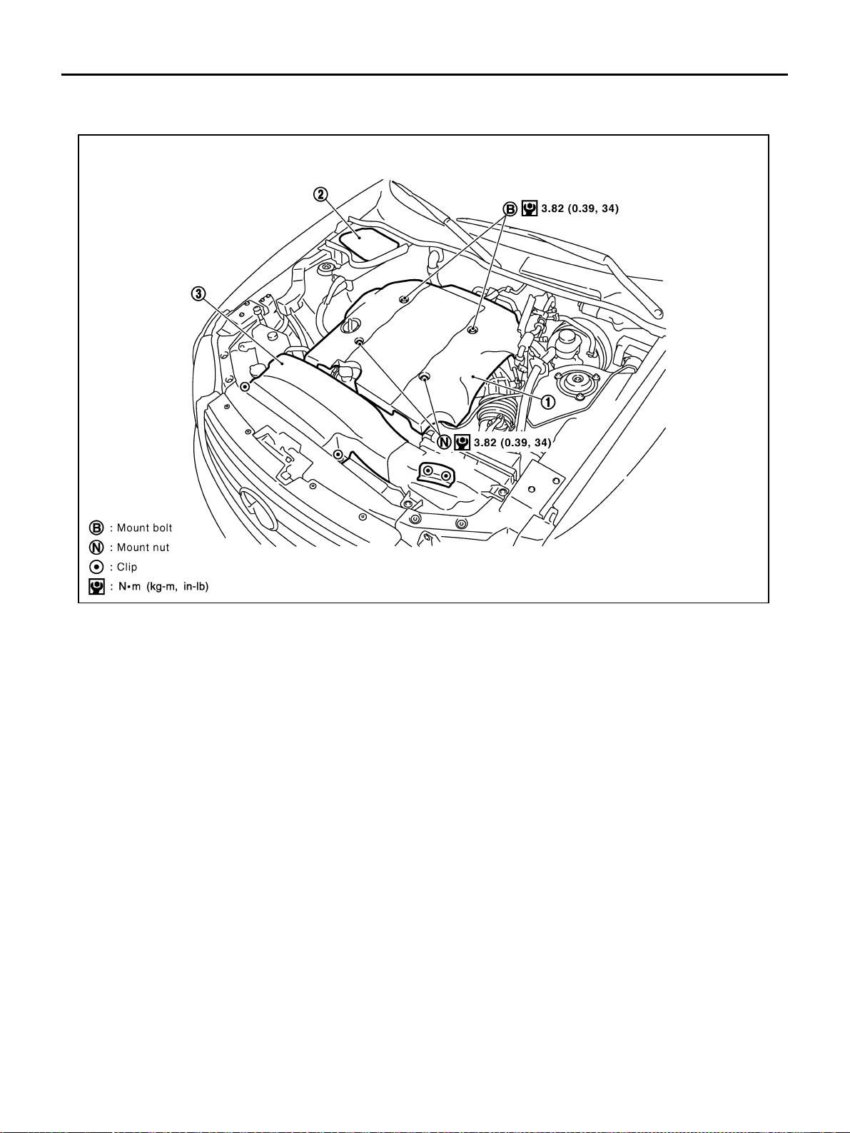
EM-168
[VK45DE]
ENGINE ROOM COVER
Revision: 2004 November 2004 FX35/FX45
ENGINE ROOM COVER PFP:14049
Removal and Installation ABS006I6
REMOVAL
CAUTION:
Do not damage or scratch cover when installing or removing.
● Major parts and inspection points under each cover are as follows; (numbered as in the figure)
INSTALLATION
Install in the reverse order of removal.
1. Engine cover 2. Battery cover 3. Air duct (inlet)
PBIC1540E
1 : Upper side of engine assembly and power steering reservoir tank
2 : Relay and battery
3 : Engine assembly front side, drive belts and cooling fan
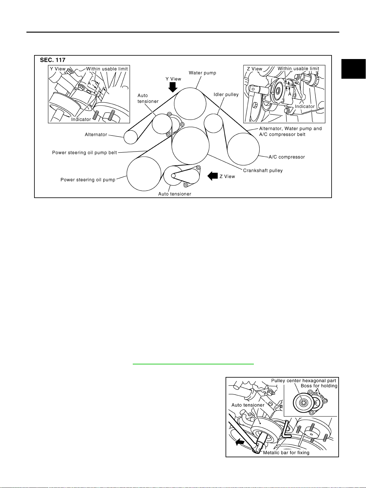
DRIVE BELTS
EM-169
[VK45DE]
C
D
E
F
G
H
I
J
K
L
M
A
EM
Revision: 2004 November 2004 FX35/FX45
DRIVE BELTS PFP:02117
Checking Drive Belts ABS006I7
WARNING:
Be sure to perform when engine is stopped.
● Remove air duct (inlet) when inspecting drive belt for alternator, water pump and A/C compressor.
● Remove front engine undercover with power tool when inspecting power steering oil pump belt.
● Make sure that indicator (single line notch) of each auto tensioner is within the allowable working range
(between three line notches).
NOTE:
● Check auto tensioner indication when engine is cold.
● When new drive belt is installed, the range should be “A”.
● The indicator notch is located on the moving side of auto tensioner for alternator, water pump and A/C
compressor belt, while it is found on the fixed side for power steering oil pump belt.
● Visually check entire belt for wear, damage or cracks.
● If the indicator is out of allowable working range or belt is damaged, replace belt.
Tension Adjustment ABS006I8
Belt tensioning is not necessary, as it is automatically adjusted by auto tensioner.
Removal and Installation ABS006I9
REMOVAL
Alternator, Water Pump and A/C Compressor Belt
1. Remove air duct (inlet). Refer to EM-172, "AIR CLEANER AND AIR DUCT" .
2. Front engine undercover with power tool.
3. With box wrench, and while securely holding the hexagonal part
in pulley center of auto tensioner, move wrench handle in the
direction of arrow (loosening direction of tensioner).
CAUTION:
Avoid placing hand in a location where pinching may occur
if the holding tool accidentally comes off.
4. Under the above condition, insert a metal bar of approximately 6
mm (0.24 in) in diameter (hexagonal bar wrench shown as
example in the figure) through the holding boss to lock auto ten-
sioner pulley arm.
● Leave auto tensioner pulley arm locked until belt is installed
again.
PBIC2331E
PBIC1542E
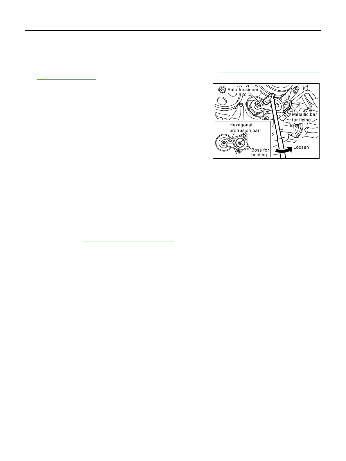
EM-170
[VK45DE]
DRIVE BELTS
Revision: 2004 November 2004 FX35/FX45
5. Remove alternator, water pump and A/C compressor belt.
Power Steering Oil Pump Belt
1. Remove air duct (inlet). Refer to EM-172, "AIR CLEANER AND AIR DUCT" .
2. Front engine undercover with power tool
3. Remove alternator, water pump and A/C compressor belt. Refer to EM-169, "
Alternator, Water Pump and
A/C Compressor Belt" .
4. While securely holding the hexagonal protrusion part of auto
tensioner pulley with box wrench, move wrench handle in the
direction of arrow (loosening direction of tensioner).
CAUTION:
Avoid placing hand in a location where pinching may occur
if holding tool accidentally comes off.
5. Under the above condition, insert a metal bar of approximately 6
mm (0.24 in) in diameter (hexagonal bar wrench shown as
example in the figure) through the holding boss to lock auto ten-
sioner pulley arm.
● Leave auto tensioner pulley arm locked until belt is installed
again.
6. Remove power steering oil pump belt.
INSTALLATION
Note to the following, and install in the reverse order of removal.
CAUTION:
● Make sure belt is securely installed around all pulleys.
● Make sure belt is correctly engaged with the pulley groove.
● Check for engine oil and engine coolant are not adhered belt and pulley groove.
● Check that belt tension is within the allowable working range, using indicator notch on auto ten-
sioner. Refer to EM-169, "
Checking Drive Belts" .
PBIC1543E
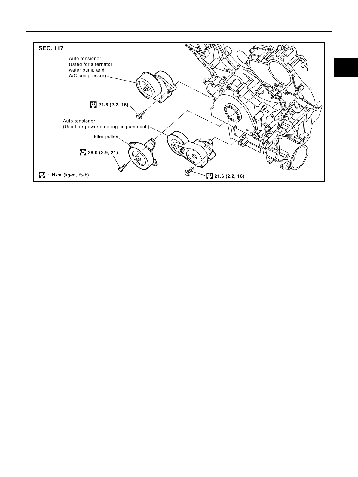
DRIVE BELTS
EM-171
[VK45DE]
C
D
E
F
G
H
I
J
K
L
M
A
EM
Revision: 2004 November 2004 FX35/FX45
Drive Belt Auto Tensioner and Idler Pulley ABS006IA
REMOVAL
1. Remove air duct (inlet). Refer to EM-172, "AIR CLEANER AND AIR DUCT" .
2. Front engine undercover with power tool.
3. Remove drive belts. Refer to EM-169, "
Removal and Installation" .
● Keep auto tensioner pulley arm locked after belt is removed.
4. Remove auto tensioner and idler pulley with power tool.
● Keep auto tensioner pulley arm locked to install or remove auto tensioner.
INSTALLATION
Install in the reverse order of removal.
PBIC1544E
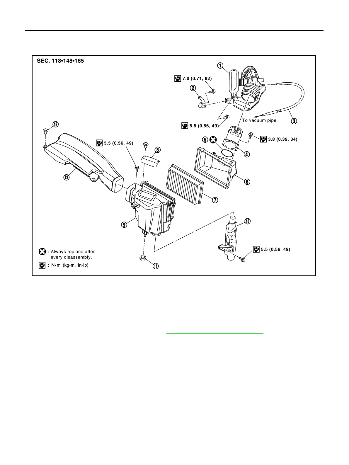
EM-172
[VK45DE]
AIR CLEANER AND AIR DUCT
Revision: 2004 November 2004 FX35/FX45
AIR CLEANER AND AIR DUCT PFP:16500
Removal and Installation ABS006IB
REMOVAL
1. Remove engine cover with power tool. Refer to EM-168, "ENGINE ROOM COVER" .
2. Disconnect harness connector from mass air flow sensor.
3. Disconnect vacuum hose and PCV hose.
4. Remove air duct (inlet), air cleaner case and mass air flow sensor assembly, air duct and resonator
assembly disconnecting their joints.
● Add marks as necessary for easier installation.
5. Remove mass air flow sensor from air cleaner case.
CAUTION:
Handle mass air flow sensor with following cares.
● Do not shock it.
● Do not disassemble it.
● Do not touch its sensor.
INSTALLATION
Note to the following, and install in the reverse order of removal.
1. Air duct and resonator assembly 2. Bracket 3. Vacuum hose
4. Mass air flow sensor 5. O-ring 6. Air cleaner case
7. Air cleaner filter 8. Cover 9. Air cleaner case
10. Resonator 11. Mounting rubber 12. Air duct (inlet)
13. Clip
PBIC1657E

AIR CLEANER AND AIR DUCT
EM-173
[VK45DE]
C
D
E
F
G
H
I
J
K
L
M
A
EM
Revision: 2004 November 2004 FX35/FX45
● Align marks. Attach each joint. Screw clamps firmly.
Changing Air Cleaner Filter ABS00A2T
REMOVAL
1. Remove air duct (inlet), air cleaner case and mass air flow sensor assembly.
2. Remove air cleaner filter from air cleaner case.
INSTALLATION
Install in the reverse order of removal.
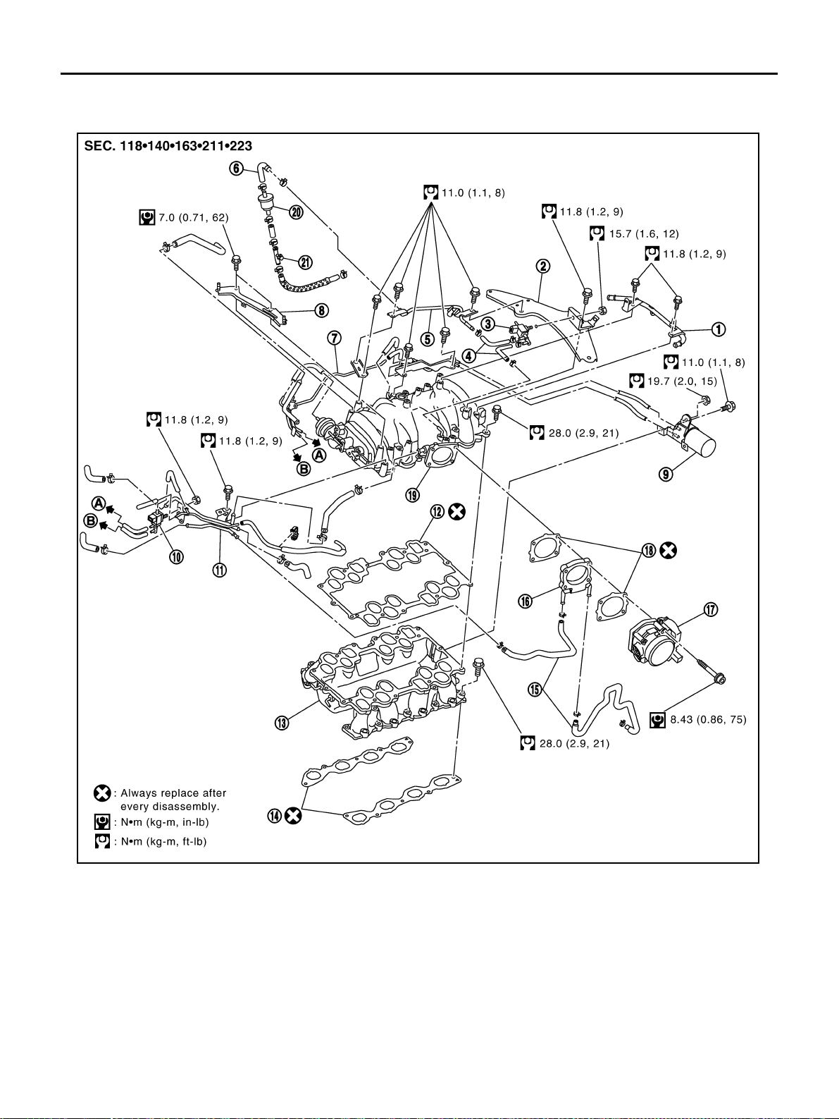
EM-174
[VK45DE]
INTAKE MANIFOLD
Revision: 2004 November 2004 FX35/FX45
INTAKE MANIFOLD PFP:14003
Removal and Installation ABS006IC
REMOVAL
WARNING:
To avoid the danger of being scalded, never drain the engine coolant when the engine is hot.
1. PCV tube 2. Engine cover rear bracket 3.
EVAP canister purge control sole-
noid valve
4. EVAP hose 5. EVAP tube 6. EVAP hose
7. Vacuum gallery 8. Engine cover front bracket 9. Vacuum tank
10. VIAS control solenoid valve 11. Water gallery 12. Gasket
13. Intake manifold (lower) 14. Gasket 15. Water hose
16. Intake manifold adapter 17. Electric throttle control actuator 18. Gasket
19. Intake manifold (upper) 20. Resonator 21. EVAP service port
PBIC3502E
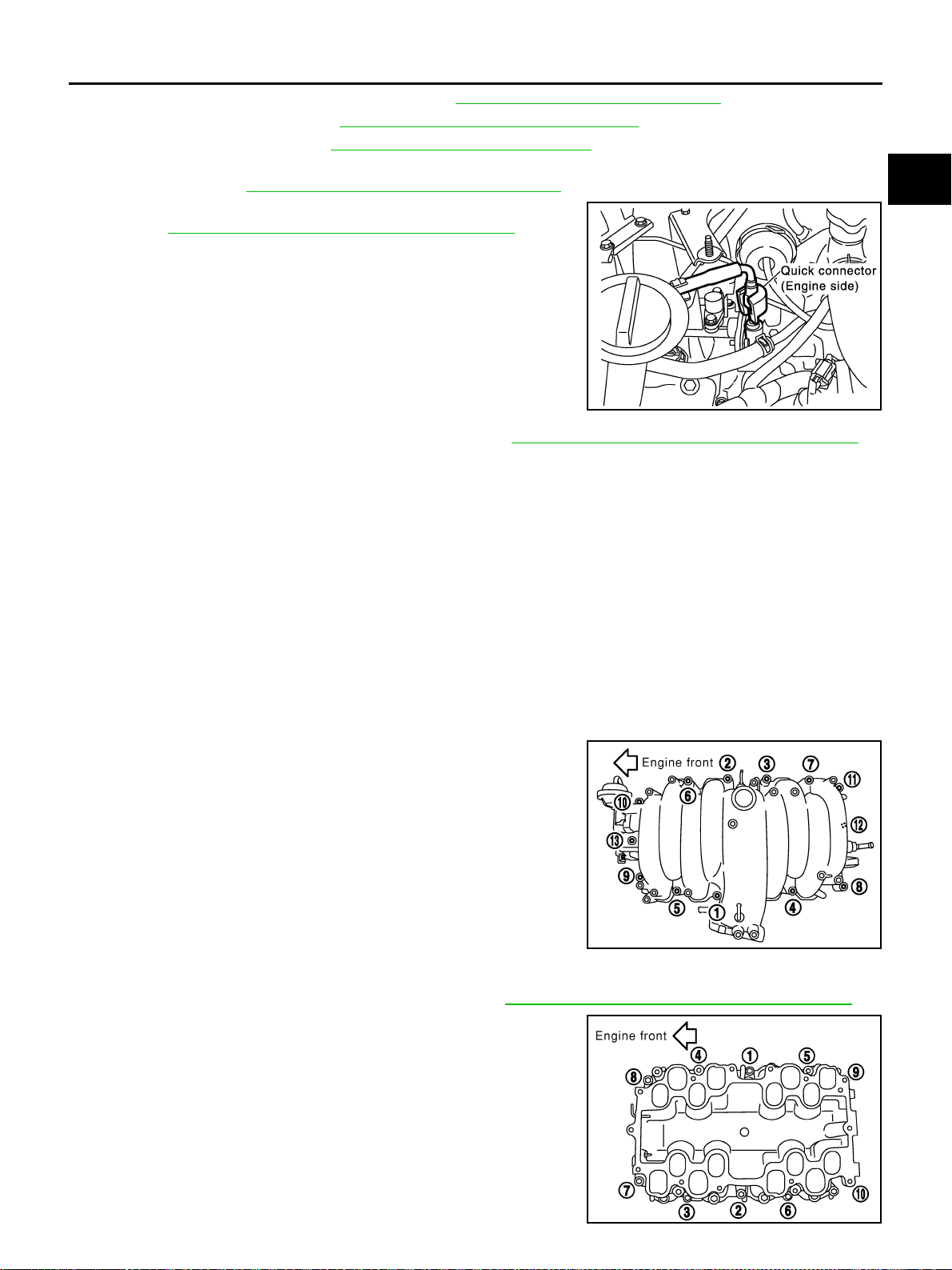
INTAKE MANIFOLD
EM-175
[VK45DE]
C
D
E
F
G
H
I
J
K
L
M
A
EM
Revision: 2004 November 2004 FX35/FX45
1. Remove engine cover with power tool. Refer to EM-168, "ENGINE ROOM COVER" .
2. Release fuel pressure. Refer to EC-700, "
FUEL PRESSURE RELEASE" .
3. Drain engine coolant. Refer to CO-36, "
Changing Engine Coolant" .
4. Remove air duct (inlet), air cleaner case and mass air flow sensor assembly, air duct and resonator
assembly. Refer to EM-172, "
AIR CLEANER AND AIR DUCT" .
5. Disconnect fuel feed hose quick connector on engine side.
Refer to EM-188, "
FUEL INJECTOR AND FUEL TUBE" .
6. Remove fuel damper and fuel hose assembly. Refer to EM-188, "
FUEL INJECTOR AND FUEL TUBE" .
CAUTION:
● While hoses are disconnected, plug them to prevent fuel from draining.
● Do not separate fuel damper and fuel hose.
7. Remove or disconnect harnesses, brackets, vacuum hose, vacuum gallery and PCV hose and tube from
intake manifold (upper).
8. Remove electric throttle control actuator as follows:
a. Disconnect harness connector.
b. Loosen mounting bolts diagonally.
CAUTION:
● Handle carefully to avoid any shock to electric throttle control actuator.
● Do not disassemble.
9. Disconnect water hoses from water gallery.
10. Remove intake manifold adaptor and water gallery.
11. Loosen bolts in reverse order as shown in the figure to remove
intake manifold (upper) with power tool.
12. Remove vacuum tank form intake manifold (lower).
13. Remove fuel injector and fuel tube assembly. Refer to EM-188, "
FUEL INJECTOR AND FUEL TUBE" .
14. Loosen bolts in reverse order as shown in the figure to remove
intake manifold (lower) with power tool.
SBIA0353E
PBIC0014E
PBIC0015E
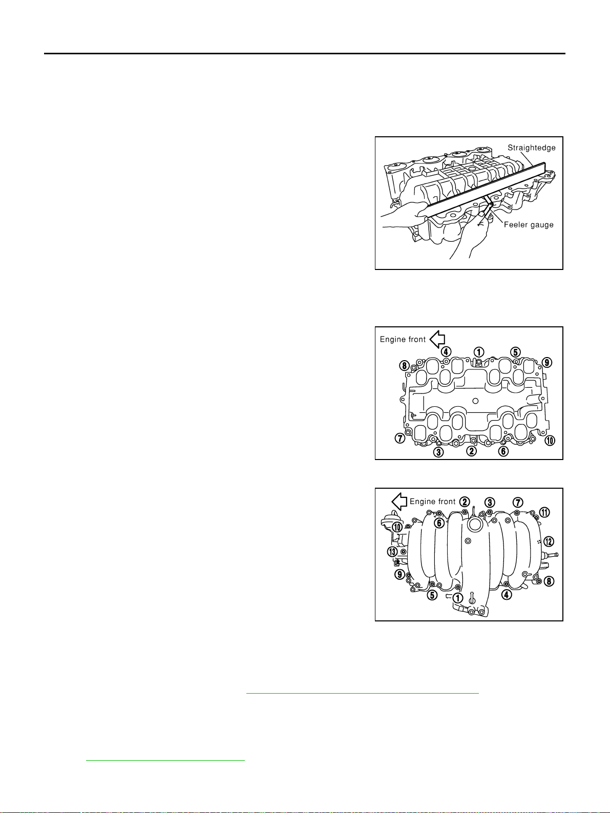
EM-176
[VK45DE]
INTAKE MANIFOLD
Revision: 2004 November 2004 FX35/FX45
15. Remove intake manifold gaskets.
CAUTION:
Cover engine openings to avoid entry of foreign materials.
INSPECTION AFTER REMOVAL
Surface Distortion
● Check the surface distortion of both the intake manifold (upper
and lower) mating surfaces with straightedge and feeler gauge.
● If it exceeds the limit, replace intake manifolds (lower and/or
upper).
INSTALLATION
Note to the following, and install in the reverse order of removal:
Intake Manifold (Lower)
Tighten in numerical order as shown in the figure.
● There are two types of mounting bolts. Refer to the following for
locating bolts.
Intake Manifold (Upper)
Tighten in numerical order as shown in the figure.
● There are two types of mounting bolts. Refer to the following for
locating bolts
Electric Throttle Control Actuator
● Install intake manifold adapter gasket and electric throttle control actuator gasket so that three protrusions
for installation identification do not face downward.
● Tighten mounting bolts of electric throttle control actuator equally and diagonally in several steps.
● After installation perform procedure in EM-177, "INSPECTION AFTER INSTALLATION" .
Water Hose
Insert hose by 27 to 32 mm (1.06 to 1.26 in) from connector end.
Vacuum Hose
Refer to EC-677, "Vacuum Hose Drawing" .
Limit : 0.1 mm (0.004 in)
PBIC0016E
M8 × 90 mm (3.54 in) : 7, 8
M8 × 35 mm (1.38 in) Except the above
PBIC0015E
M8 × 80 mm (3.15 in) : 4, 5, 6, 7
M8 × 25 mm (0.98 in) : Except the above
PBIC0014E

INTAKE MANIFOLD
EM-177
[VK45DE]
C
D
E
F
G
H
I
J
K
L
M
A
EM
Revision: 2004 November 2004 FX35/FX45
INSPECTION AFTER INSTALLATION
● Perform the “Throttle Valve Closed Position Learning” when harness connector of electric throttle control
actuator is disconnected. Refer to EC-698, "
Throttle Valve Closed Position Learning" .
● Perform the “Idle Air Volume Learning” and “Throttle Valve Closed Position Learning” when electric throt-
tle control actuator is replaced. Refer to EC-698, "
Idle Air Volume Learning" .
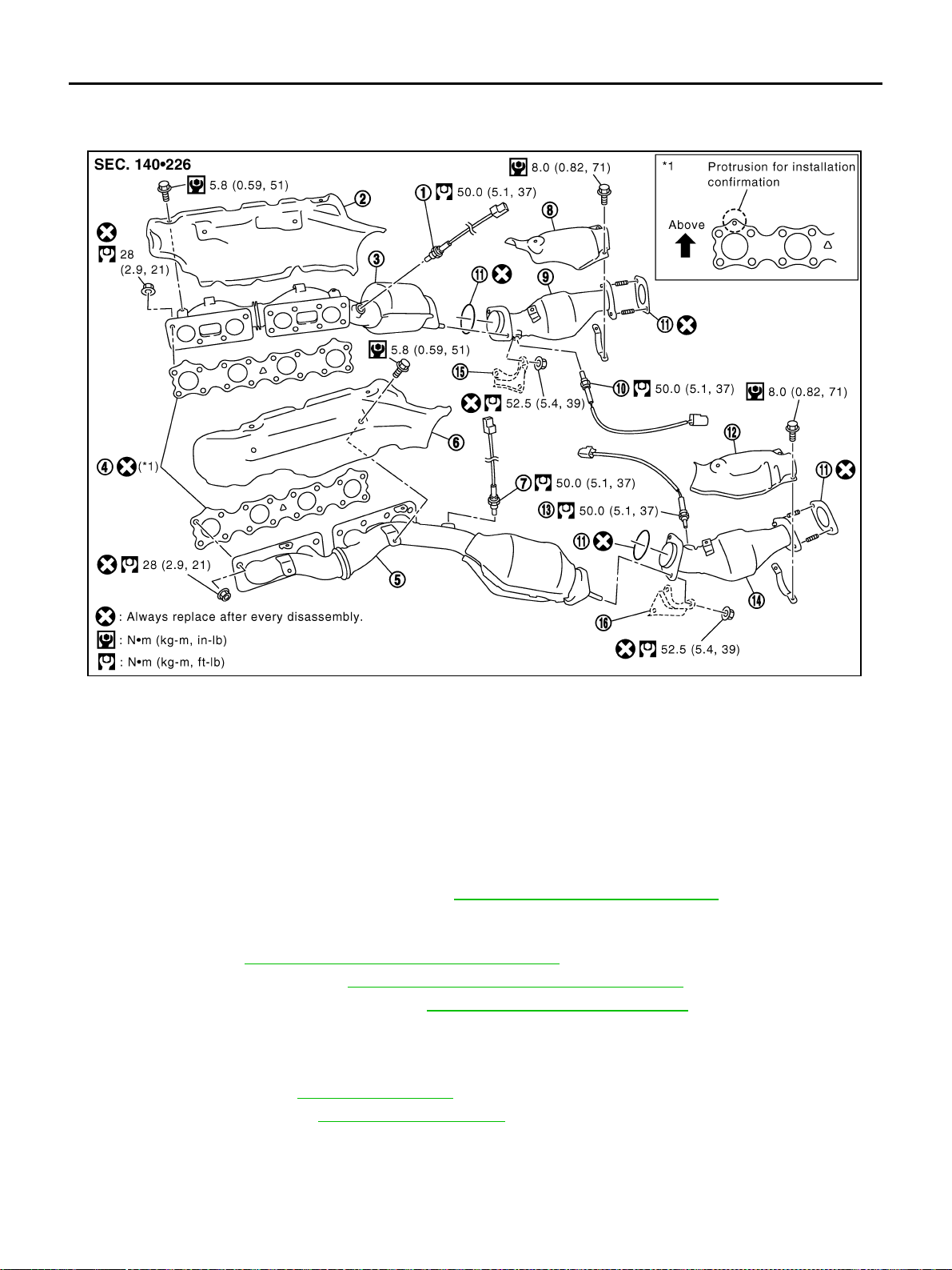
EM-178
[VK45DE]
EXHAUST MANIFOLD AND THREE WAY CATALYST
Revision: 2004 November 2004 FX35/FX45
EXHAUST MANIFOLD AND THREE WAY CATALYST PFP:14004
Removal and Installation ABS006ID
REMOVAL
WARNING:
Perform the work, when the exhaust and cooling system have completely cooled down.
1. Remove engine cover with power tool. Refer to EM-168, "
ENGINE ROOM COVER" .
2. Remove front and rear engine undercovers with power tool.
3. Remove air duct (inlet), air cleaner case and mass air flow sensor assembly, air duct and resonator
assembly. Refer to EM-172, "
AIR CLEANER AND AIR DUCT" .
4. Remove front cross bar. Refer to FSU-6, "
FRONT SUSPENSION ASSEMBLY" .
5. Drain engine coolant from radiator. Refer to CO-36, "
Changing Engine Coolant" .
CAUTION:
● Perform this step when engine is cold.
● Do not spill engine coolant on drive belts.
6. Remove radiator. Refer to CO-39, "
RADIATOR" .
7. Remove drive belts. Refer to EM-169, "
DRIVE BELTS" .
8. Remove heated oxygen sensors as follows:
a. Disconnect harness connector of each heated oxygen sensors.
1. Heated oxygen sensor 1 (bank 2) 2. Exhaust manifold cover (right bank) 3. Exhaust manifold (right bank)
4. Gasket 5. Exhaust manifold (left bank) 6. Exhaust manifold cover (left bank)
7. Heated oxygen sensor 1 (bank 1) 8. Three way catalyst cover (right bank) 9. Three way catalyst (right bank)
10. Heated oxygen sensor 2 (bank 2) 11. Gasket 12. Three way catalyst cover (left bank)
13. Heated oxygen sensor 2 (bank 1) 14. Three way catalyst (left bank) 15. Mounting bracket
16. Mounting bracket
PBIC3503E
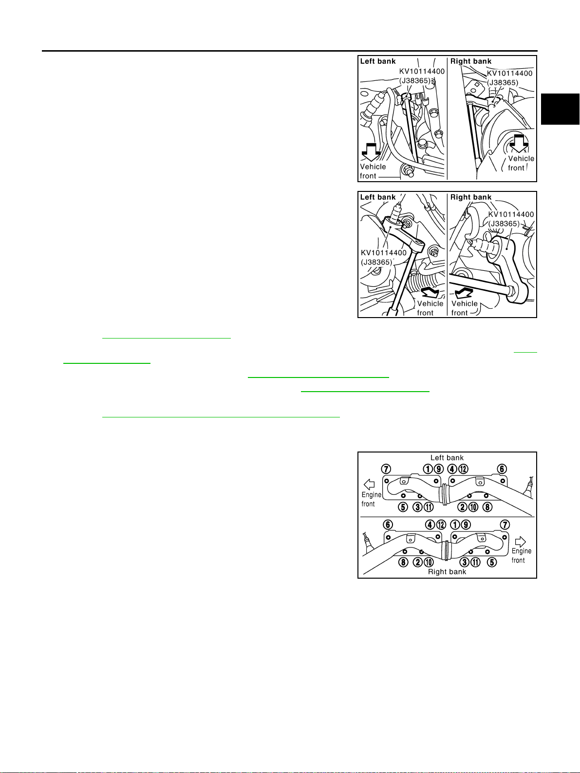
EXHAUST MANIFOLD AND THREE WAY CATALYST
EM-179
[VK45DE]
C
D
E
F
G
H
I
J
K
L
M
A
EM
Revision: 2004 November 2004 FX35/FX45
b. Remove heated oxygen sensor 1 and 2 on both bank with
heated oxygen sensor wrench (SST).
● Put marks to identify installation positions of each heated oxy-
gen sensor.
CAUTION:
● Be careful not to damage heated oxygen sensor.
● Discard any heated oxygen sensor which has been
dropped from a height of more than 0.5 m (19.7 in) onto a
hard surface such as a concrete floor; replace with a new
one.
9. Remove exhaust mounting bracket between three way catalysts (right and left bank) and transmission.
Refer to EX-3, "
EXHAUST SYSTEM" .
10. Disconnect A/C piping from A/C compressor, then remove A/C compressor with power tool. Refer to ATC-
139, "Components" .
11. Remove alternator and bracket. Refer to SC-23, "
CHARGING SYSTEM" .
12. Remove exhaust front tube with power tool. Refer to EX-3, "
EXHAUST SYSTEM" .
13. Remove steering lower joint at power steering gear assembly side, and release steering lower shaft.
Refer to PS-19, "
POWER STEERING GEAR AND LINKAGE" .
14. Remove three way catalysts (right and left bank).
15. Remove exhaust manifold covers. (right and left bank)
16. Loosen mounting nuts in reverse order as shown in the figure to
remove exhaust manifold.
NOTE:
Disregard the numerical order No. 9 to 12 in removal.
17. Remove exhaust manifold gaskets.
CAUTION:
Cover engine openings to avoid entry of foreign materials.
PBIC2333E
PBIC2334E
PBIC1549E
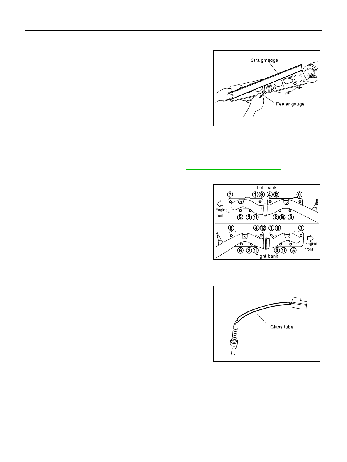
EM-180
[VK45DE]
EXHAUST MANIFOLD AND THREE WAY CATALYST
Revision: 2004 November 2004 FX35/FX45
INSPECTION AFTER REMOVAL
Surface Distortion
● Check the surface distortion of the each exhaust manifold flange
mating surface with straightedge and feeler gauge.
● If it exceeds the limit, replace exhaust manifold.
INSTALLATION
Note the following, and install in the reverse order of removal.
Exhaust Manifold Gasket
Install exhaust manifold gasket with its directional protrusion set upward.
Refer to the figure of components on former page. Refer to EM-178, "
Removal and Installation" .
Exhaust Manifold
● Install exhaust manifold in numerical order as shown in the fig-
ure.
NOTE:
Tighten mounting nuts No. 1 to 4 in two steps. The numerical
order No. 9 to 12 shown second steps.
Heated Oxygen Sensor
● Install heated oxygen sensors in the original position.
● Install referring the following if the installation positions cannot
be identified.
*: The length of glass tube of bank 2 is longer than the one
of bank 1.
CAUTION:
● Before installing a new heated oxygen sensor, clean
exhaust system threads using oxygen sensor thread
cleaner (commercial service tool: J-43897-18 or J-43897-12), and apply anti-seize lubricant (com-
mercial service tool).
● Do not over torque heated oxygen sensor. Doing so may cause damage to the heated oxygen sen-
sor, resulting in “MIL” coming on.
Limit : 0.3 mm (0.012 in)
PBIC1550E
PBIC1549E
Glass tube color
Heated oxygen sensor 1* : Black
Heated oxygen sensor 2 : White
PBIC2652E
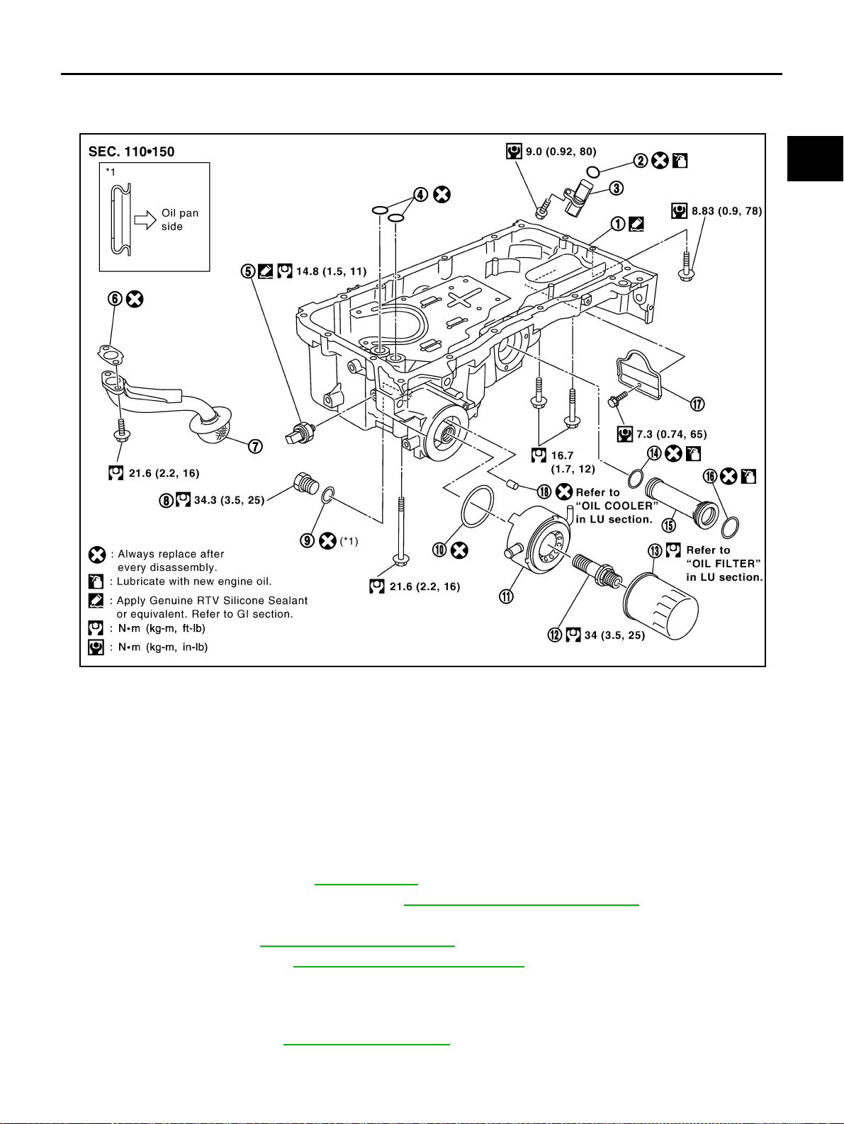
OIL PAN AND OIL STRAINER
EM-181
[VK45DE]
C
D
E
F
G
H
I
J
K
L
M
A
EM
Revision: 2004 November 2004 FX35/FX45
OIL PAN AND OIL STRAINER PFP:11110
Removal and Installation ABS006IE
REMOVAL
WARNING:
To avoid the danger of being scalded, do not drain engine oil when engine is hot.
1. Remove front tire.
2. Remove hood assembly. Refer to BL-14, "
HOOD" .
3. Remove engine cover with power tool. Refer to EM-168, "
ENGINE ROOM COVER" .
4. Remove front and rear engine undercovers with power tool.
5. Drain engine oil. Refer to LU-26, "
Changing Engine Oil" .
6. Drain engine coolant. Refer to CO-36, "
Changing Engine Coolant" .
CAUTION:
● Perform this step when engine is cold.
● Do not spill engine coolant on drive belts.
7. Remove drive belts. Refer to EM-169, "
DRIVE BELTS" .
1. Oil pan 2. O-ring 3. Crankshaft position sensor (POS)
4. O-ring 5. Oil pressure switch 6. Gasket
7. Oil strainer 8. Drain plug 9. Drain plug washer
10. O-ring 11. Oil cooler 12. Connector bolt
13. Oil filter 14. O-ring 15. Axle pipe
16. O-ring 17. Rear plate cover 18. Relief valve
PBIC1552E
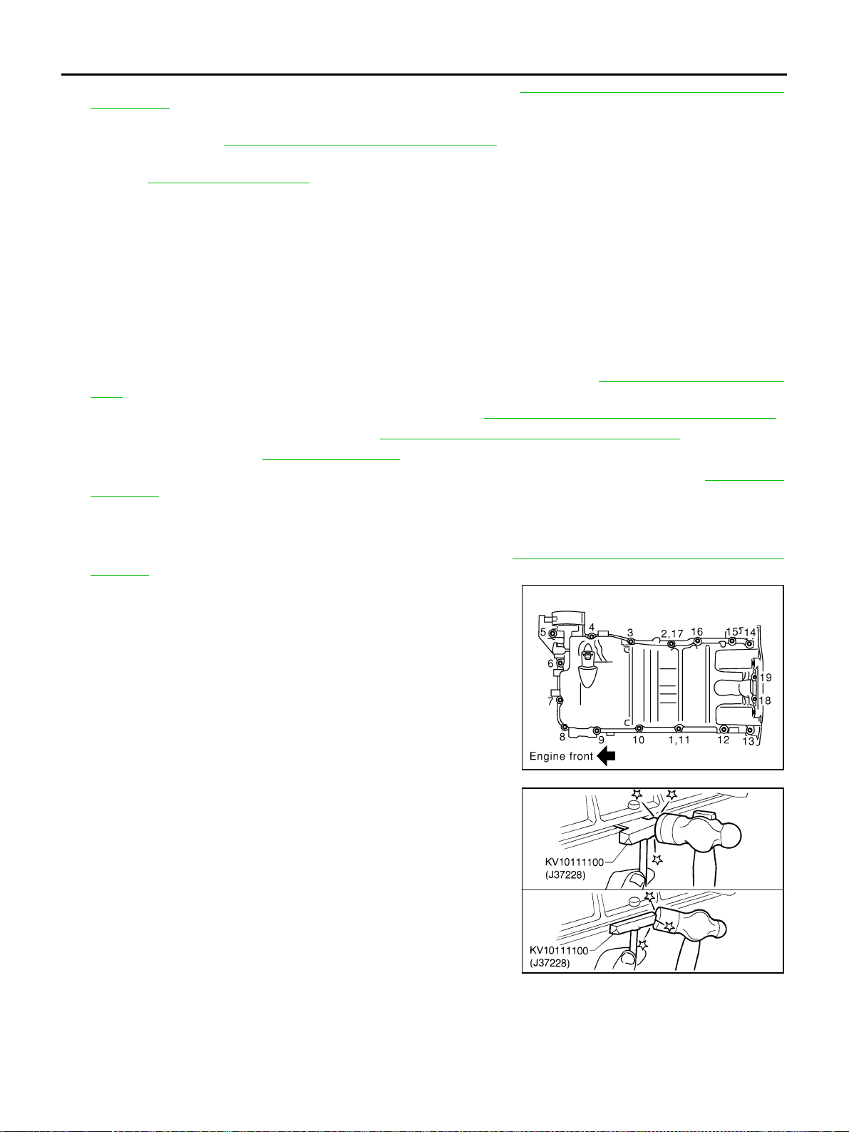
EM-182
[VK45DE]
OIL PAN AND OIL STRAINER
Revision: 2004 November 2004 FX35/FX45
8. Remove auto tensioner of power steering oil pump belt. Refer to EM-171, "Drive Belt Auto Tensioner and
Idler Pulley" .
9. Remove power steering oil pump with piping connected, and temporarily secure it aside with ropes or
equivalent. Refer to PS-31, "
POWER STEERING OIL PUMP" .
10. Remove A/C compressor with piping connected, and temporarily secure it aside with ropes or equivalent.
Refer to ATC-139, "
Components" .
11. Remove A/C compressor fitting bolts, and install A/C compressor temporarily on vehicle side with ropes or
equivalent.
12. Remove harness of lower side of oil pan.
13. Remove crankshaft position sensor (POS) from transmission.
CAUTION:
● Handle carefully to avoid dropping and shocks.
● Do not disassemble it.
● Do not allow metal powder to adhere to magnetic part at sensor tip.
● Do not place sensors in a location where they are exposed to magnetism.
14. Install engine slinger and hang engine assembly to secure position. Refer to EM-236, "
ENGINE ASSEM-
BLY" .
15. Remove front suspension member with power tool. Refer to FSU-17, "
FRONT SUSPENSION MEMBER" .
16. Remove front final drive assembly. Refer to FFD-10, "
FRONT FINAL DRIVE ASSEMBLY" .
17. Remove oil filter. Refer to LU-28, "
OIL FILTER" .
18. Disconnect oil cooler water hoses, and remove oil cooler water pipe and oil cooler. Refer to LU-29, "
OIL
COOLER" .
19. Remove oil pan as the follows:
a. Remove rear plate cover.
b. Remove transmission joint bolts which pierce oil pan. Refer to AT-269, "
Removal and Installation (AWD
models)" .
c. Loosen oil pan bolts with power tool in reverse order as shown
in the figure.
NOTE:
Disregard the numerical order No. 11 and No. 17 in removal.
d. Insert seal cutter (SST) between oil pan and cylinder block.
Slide seal cutter by tapping on the side of seal cutter with ham-
mer. Remove oil pan.
CAUTION:
● Be careful not to damage the mating surface.
● Do not insert flat-blade screwdriver, this will damage the
mating surface.
e. Remove O-rings from bottom of oil pump and front cover.
20. As necessary, pull axle pipe from oil pan.
● Hold pipes and pull them out to front drive shaft (left) installing side.
21. Remove oil strainer.
PBIC0194E
SEM365E
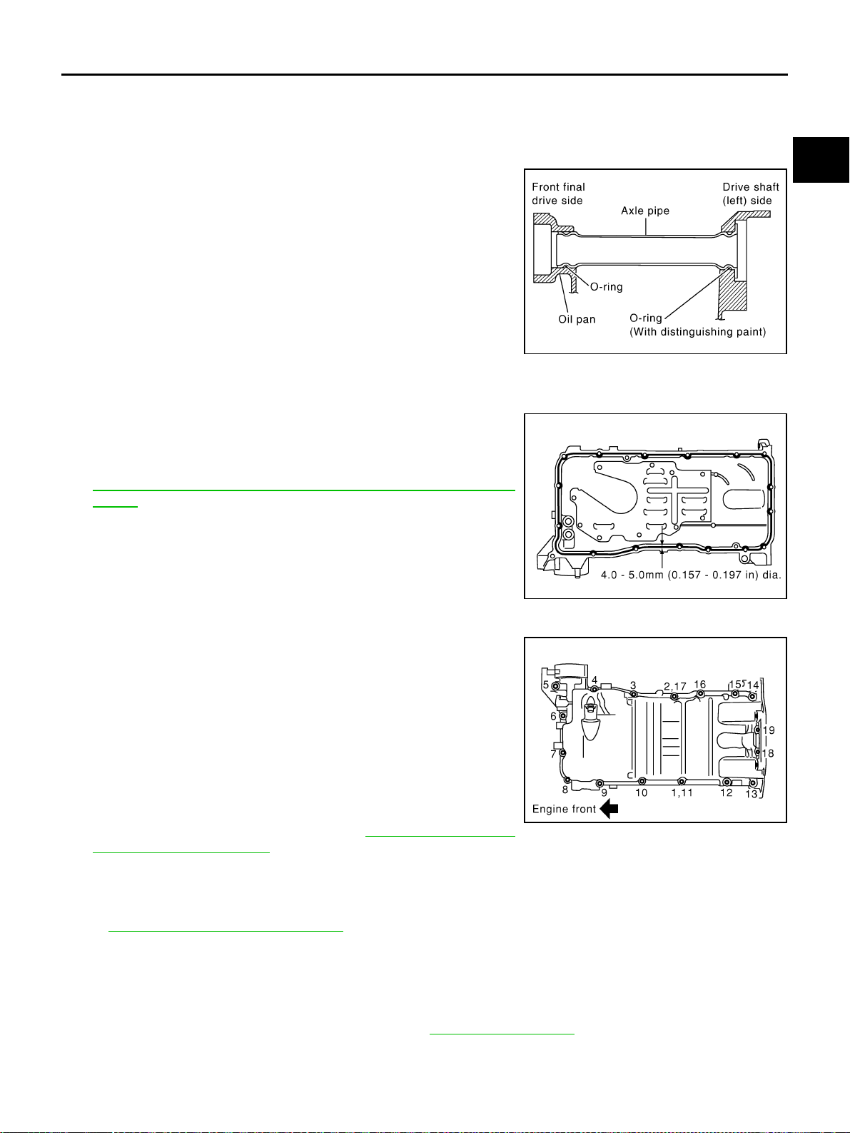
OIL PAN AND OIL STRAINER
EM-183
[VK45DE]
C
D
E
F
G
H
I
J
K
L
M
A
EM
Revision: 2004 November 2004 FX35/FX45
INSPECTION AFTER REMOVAL
Clean oil strainer if any object attached.
INSTALLATION
1. Install oil strainer.
2. Install axle pipe to oil pan, if removed.
● Lubricate O-ring groove of axle pipe, O-ring, and O-ring joint
of oil pan with new engine oil.
● Right/left O-ring diameters differ from each other. O-ring with
identification paint mark is installed on front drive shaft (left)
installing side.
● Install axle pipe to oil pan from (left) side.
CAUTION:
Insert it with care to prevent O-ring from sliding.
3. Install oil pan as follows:
a. Install new O-rings to oil pump and front cover side.
b. Apply a continuous bead of liquid gasket with tube presser [SST:
WS39930000 ( — )] to the cylinder block mating surface of
oil pan to a limited portion as shown in the figure.
Use Genuine RTV Silicone Sealant or equivalent. Refer to
GI-48, "
RECOMMENDED CHEMICAL PRODUCTS AND SEAL-
ANTS".
CAUTION:
Attaching should be done within 5 minutes after coating.
c. Install oil pan.
● Tighten bolts in numerical order as shown in the figure.
NOTE:
Tighten bolts No. 1 and No. 2 in two steps. The numerical
order No. 11 and No. 17 shown second steps.
● There are three types of mounting bolts. Refer to the following
for locating bolts.
d. Tighten transmission joint bolts. Refer to AT-269, "
Removal and
Installation (AWD models)" .
e. Install rear plate cover.
4. Install oil pan drain plug with new drain plug washer.
● Refer to the figure of components of former page for installation direction of drain plug washer. Refer to
EM-181, "
Removal and Installation" .
5. Install in the reverse order of removal after this step.
NOTE:
At least 30 minutes after oil pan is installed, pour engine oil.
INSPECTION AFTER INSTALLATION
1. Check engine oil level and add engine oil. Refer to LU-25, "ENGINE OIL" .
2. Start engine, and check there is no leak of engine oil.
3. Stop engine and wait for 15 minutes.
PBIC2336E
PBIC0195E
M6 × 30 mm (1.18 in) : 18, 19
M8 × 100 mm (3.94 in) : 5, 9
M8 × 45 mm (1.77 in) : Except the above
PBIC0194E

EM-184
[VK45DE]
OIL PAN AND OIL STRAINER
Revision: 2004 November 2004 FX35/FX45
4. Check engine oil level again. Refer to LU-25, "ENGINE OIL" .
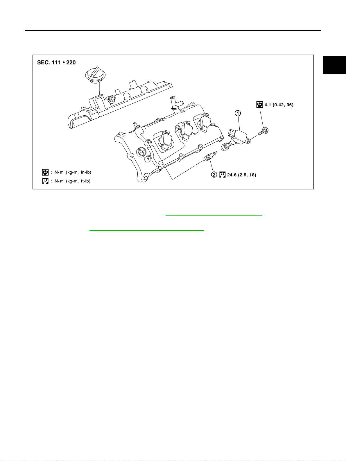
IGNITION COIL
EM-185
[VK45DE]
C
D
E
F
G
H
I
J
K
L
M
A
EM
Revision: 2004 November 2004 FX35/FX45
IGNITION COIL PFP:22448
Removal and Installation ABS006IF
REMOVAL
1. Remove engine cover with power tool. Refer to EM-168, "ENGINE ROOM COVER" .
2. Remove air duct (inlet), air cleaner case and mass air flow sensor assembly, air duct and resonator
assembly. Refer to EM-172, "
AIR CLEANER AND AIR DUCT" .
3. Disconnect harness connector from ignition coil.
4. Remove ignition coil.
CAUTION:
Do not shock it.
INSTALLATION
Install in the reverse order of removal.
1. Ignition coil 2. Spark plug
PBIC1589E
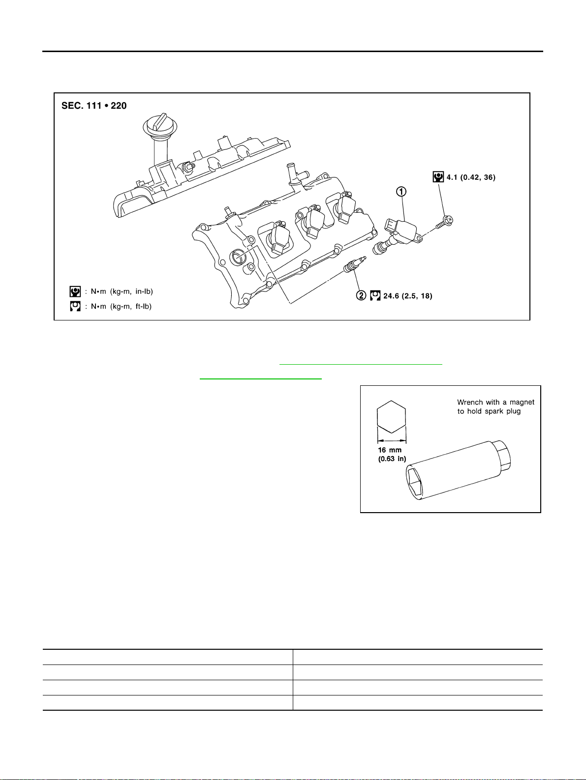
EM-186
[VK45DE]
SPARK PLUG (PLATINUM-TIPPED TYPE)
Revision: 2004 November 2004 FX35/FX45
SPARK PLUG (PLATINUM-TIPPED TYPE) PFP:22401
Removal and Installation ABS006IG
REMOVAL
1. Remove engine cover with power tool. Refer to EM-168, "ENGINE ROOM COVER" .
2. Remove ignition coil. Refer to EM-185, "
IGNITION COIL" .
3. Remove spark plug with spark plug wrench (commercial service
tool).
INSPECTION AFTER REMOVAL
Use standard type spark plug for normal condition.
Hot type spark plug is suitable when fouling occurs with standard type spark plug under conditions such as:
● Frequent engine starts
● Low ambient temperatures
Cold type spark plug is suitable when spark plug knock occurs with standard type spark plug under conditions
such as:
● Extended highway driving
● Frequent high engine revolution
1. Ignition coil 2. Spark plug
PBIC1589E
SEM294A
Make NGK
Standard type PLFR5A-11
Hot type PLFR4A-11
Cold type PLFR6A-11
Gap (Nominal) : 1.1 mm (0.043 in)
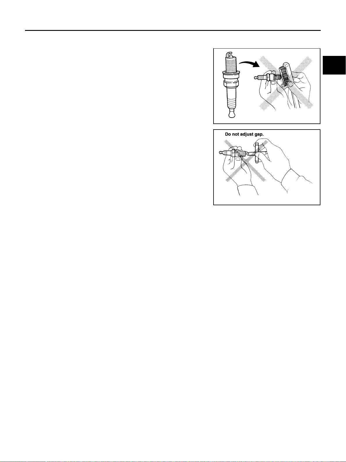
SPARK PLUG (PLATINUM-TIPPED TYPE)
EM-187
[VK45DE]
C
D
E
F
G
H
I
J
K
L
M
A
EM
Revision: 2004 November 2004 FX35/FX45
CAUTION:
● Do not drop or shock spark plug.
● Do not use wire brush for cleaning.
● If plug tip is covered with carbon, spark plug cleaner may
be used.
● Checking and adjusting plug gap is not required between
change intervals.
INSTALLATION
Install in the reverse order of removal.
Cleaner air pressure:
Less than 588 kPa (6 kg/cm
2
, 85 psi)
Cleaning time:
Less than 20 seconds
SMA773C
SMA806CA
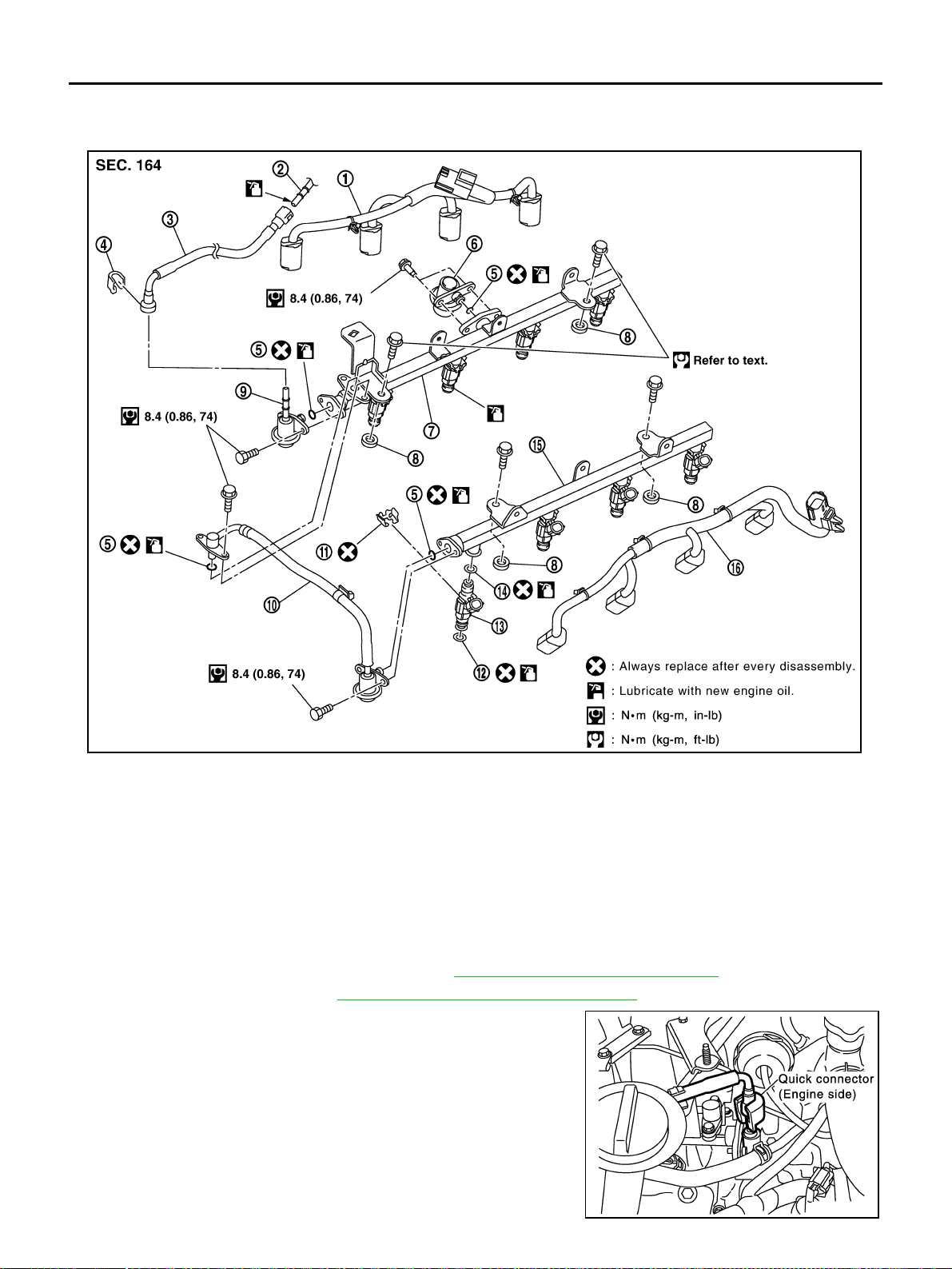
EM-188
[VK45DE]
FUEL INJECTOR AND FUEL TUBE
Revision: 2004 November 2004 FX35/FX45
FUEL INJECTOR AND FUEL TUBE PFP:16600
Removal and Installation ABS006IH
CAUTION:
Do not remove or disassemble parts unless instructed as shown in the figure.
REMOVAL
1. Remove engine cover with power tool. Refer to EM-168, "ENGINE ROOM COVER" .
2. Release fuel pressure. Refer to EC-700, "
FUEL PRESSURE RELEASE" .
3. Disconnect fuel feed hose on engine side as follows: (Excepting
to confirm whether or not there is quick connector cap, perform
same procedure for the side of centralized under-floor piping as
well.)
1. Fuel injector sub harness (RH) 2. Centralized under-floor piping 3. Fuel feed hose
4. Quick connector cap 5. O-ring 6. Fuel damper (RH)
7. Fuel tube (RH) 8. Spacer 9. Fuel feed damper
10. Fuel damper and fuel hose assembly 11. Clip 12. O-ring (Green)
13. Fuel injector 14. O-ring (Black) 15. Fuel tube (LH)
16. Fuel injector sub harness (LH)
PBIC2335E
SBIA0353E
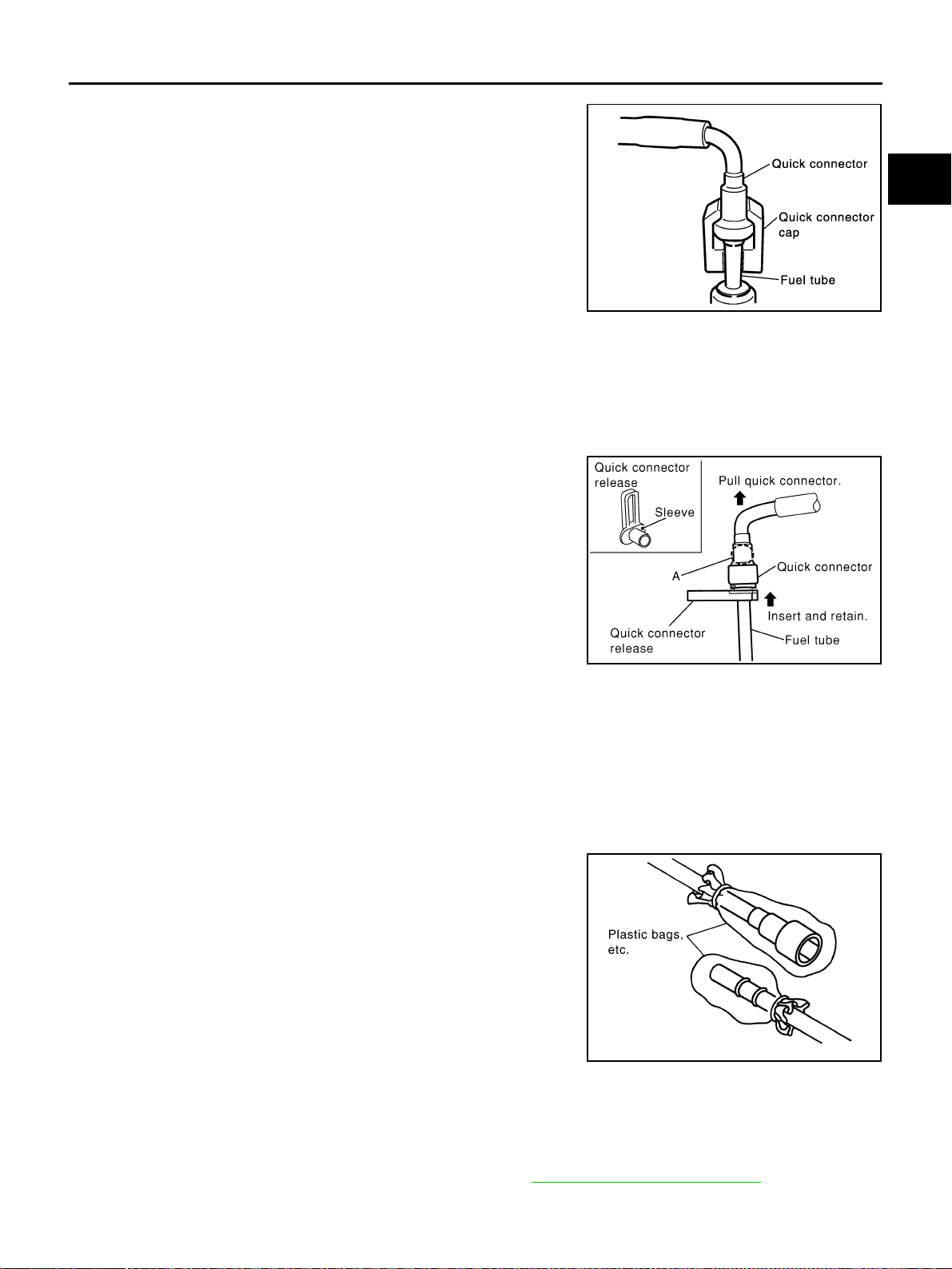
FUEL INJECTOR AND FUEL TUBE
EM-189
[VK45DE]
C
D
E
F
G
H
I
J
K
L
M
A
EM
Revision: 2004 November 2004 FX35/FX45
a. Remove quick connector cap from quick connector connection.
(engine side only)
b. Disconnect quick connector from fuel feed damper as the following:
CAUTION:
Disconnect quick connector by using quick connector release [SST: J-45488], not by picking out
retainer tabs (centralized under-floor piping side).
i. With the sleeve side of quick connector release facing quick connector, install quick connector release
onto fuel tube.
ii. Insert quick connector release into quick connector until sleeve
contacts and goes no further. Hold quick connector release on
that position.
CAUTION:
Inserting quick connector release hard will not disconnect
quick connector. Hold quick connector release where it
contacts and goes no further.
iii. Draw and pull out quick connector straight from fuel damper.
CAUTION:
● Pull quick connector holding “A” position as shown in
the figure.
● Do not pull with lateral force applied. O-ring inside quick connector may be damaged.
● Prepare container and cloth beforehand as fuel will leak out.
● Avoid fire and sparks.
● Keep parts away from heat source. Especially, be careful when welding is performed around
them.
● Do not expose parts to battery electrolyte or other acids.
● Do not bend or twist connection between quick connector and fuel feed hose during installa-
tion/removal.
● To keep clean the connecting portion and to avoid dam-
age and foreign materials, cover them completely with
plastic bags or something similar.
4. Disconnect fuel damper and fuel hose assembly from fuel tubes (RH and LH).
CAUTION:
● While hoses are disconnected, plug them to prevent fuel from draining.
● Do not separate fuel damper and fuel hose.
5. Remove intake manifold (upper) with power tool. Refer to EM-174, "
INTAKE MANIFOLD" .
6. Disconnect harness connector from fuel injector.
SBIA0354E
KBIA0702E
PBIC2205E
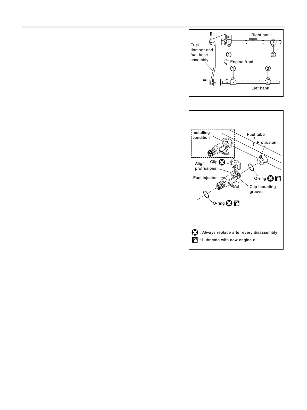
EM-190
[VK45DE]
FUEL INJECTOR AND FUEL TUBE
Revision: 2004 November 2004 FX35/FX45
7. Loosen mounting bolts in reverse order as shown in the figure,
and remove fuel tube and fuel injector assembly.
CAUTION:
Do not tilt it, or remaining fuel in pipes may flow out from
pipes.
8. Remove spacers on intake manifold (lower).
9. Remove fuel injector from fuel tube as follows:
a. Open and remove clip.
b. Remove fuel injector from fuel tube by pulling straight.
CAUTION:
● Be careful with remaining fuel that may go out from fuel
tube.
● Be careful not to damage injector nozzles during
removal.
● Do not bump or drop fuel injectors.
● Do not disassemble fuel injectors.
10. Remove fuel damper (RH) and fuel feed damper.
INSTALLATION
1. Install fuel damper (RH) and fuel feed damper.
● When handling O-rings, be careful of the following caution:
CAUTION:
● Handle O-ring with bare hands. Do not wear gloves.
● Lubricate O-ring with new engine oil.
● Do not clean O-ring with solvent.
● Make sure that O-ring and its mating part are free of foreign material.
● When installing O-ring, be careful not to scratch it with tool or fingernails. Also be careful not
to twist or stretch O-ring. If O-ring was stretched while it was being attached, do not insert it
quickly into fuel tube.
● Insert O-ring straight into fuel tube. Do not decenter or twist it.
● Insert fuel damper (RH) and fuel feed damper straight into fuel tube (RH).
● Tighten mounting bolts evenly in turn.
● After tightening mounting bolts, make sure that there is no gap between flange and fuel tube (RH).
2. Install O-rings to fuel injector paying attention to the following caution.
CAUTION:
● Upper and lower O-ring are different. Be careful not to confuse them.
PBIC2338E
PBIC1264E
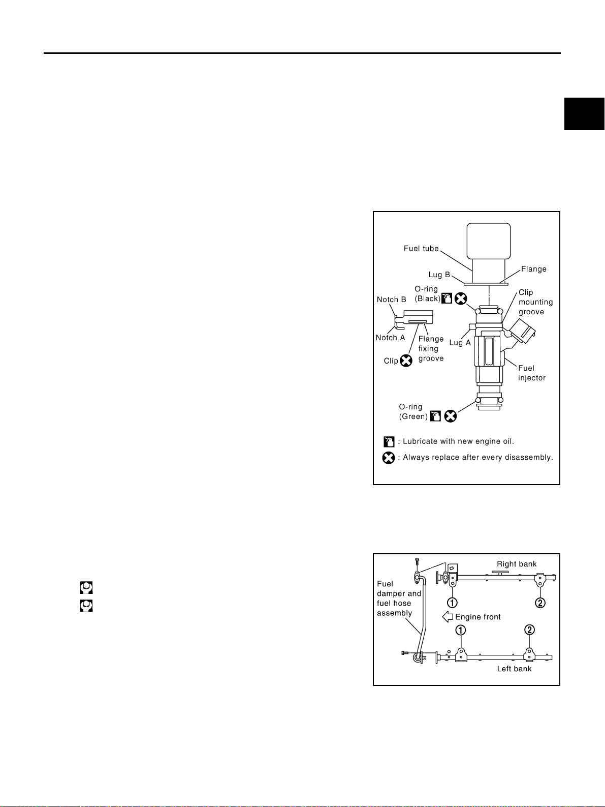
FUEL INJECTOR AND FUEL TUBE
EM-191
[VK45DE]
C
D
E
F
G
H
I
J
K
L
M
A
EM
Revision: 2004 November 2004 FX35/FX45
● Handle O-ring with bare hands. Never wear gloves.
● Lubricate O-ring with new engine oil.
● Do not clean O-ring with solvent.
● Make sure that O-ring and its mating part are free of foreign material.
● When installing O-ring, be careful not to scratch it with tool or fingernails. Also be careful not to
twist or stretch O-ring. If O-ring was stretched while it was being attached, do not insert it
quickly into fuel tube.
● Insert O-ring straight into fuel tube. Do not decenter or twist it.
3. Install fuel injector to fuel tube as follows:
a. Insert clip into clip mounting groove on fuel injector.
● Insert clip so that lug “A” of fuel injector matches notch “A” of
the clip.
CAUTION:
● Do not reuse clip. Replace it with a new one.
● Be careful to keep clip from interfering with O-ring. If
interference occurs, replace O-ring.
b. Insert fuel injector into fuel tube with clip attached.
● Insert it while matching it to the axial center.
● Insert fuel injector so that lug “B” of fuel tube matches notch
“B” of the clip.
● Make sure that fuel tube flange is securely fixed in flange fix-
ing groove on clip.
c. Make sure that installation is complete by checking that fuel
injector does not rotate or come off.
● Make sure that protrusions of fuel injectors are aligned with
cutouts of clips after installation.
4. Install spacers on intake manifold (lower).
5. Install fuel tube and fuel injector assembly to intake manifold.
CAUTION:
Be careful not to let tip of injector nozzle come in contact with other parts.
● Tighten mounting bolts in two steps in numerical order as
shown in the figure.
6. Connect fuel feed hose on engine side as the following: (Excepting to confirm whether or not there is
quick connector cap, perform same procedure for the side of centralized under-floor piping as well.)
a. Make sure no foreign substances are deposited in and around fuel tube and quick connector, and no dam-
age on them.
b. Thinly apply new engine oil around fuel tube from tip end to spool end.
c. Align center to insert quick connector straightly into fuel tube.
Fuel tube side : Black
Nozzle side : Green
PBIC2337E
1st step : 10.1 N·m (1.0 kg-m, 7 ft-lb)
2nd step : 23.5 N·m (2.4 kg-m, 17 ft-lb)
PBIC2338E
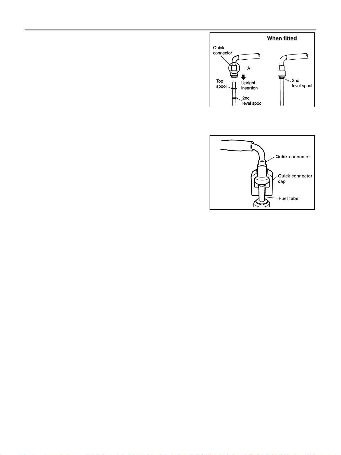
EM-192
[VK45DE]
FUEL INJECTOR AND FUEL TUBE
Revision: 2004 November 2004 FX35/FX45
● Insert fuel tube into quick connector until top spool is com-
pletely inside quick connector, and 2nd level spool exposes
right below quick connector.
● Hold “A” position as shown in the figure when inserting fuel
tube into quick connector.
CAUTION:
● Carefully align center to avoid inclined insertion to pre-
vent damage to O-ring inside quick connector.
● Insert until you hear a “click” sound and actually feel the
engagement.
● To avoid misidentification of engagement with a similar
sound, be sure to perform the next step.
d. Pull quick connector by hand holding “A” position. Make sure it is completely engaged (connected) so that
it does not come out from fuel tube.
e. Install quick connector cap on quick connector connection. (on
engine side only).
f. Install fuel feed hose to hose clamps.
7. Install in the reverse order of removal after this step.
INSPECTION AFTER INSTALLATION
Check on Fuel Leakage
1. Turn ignition switch “ON” (with engine stopped). With fuel pressure applied to fuel piping, check for fuel
leakage at connection points.
NOTE:
Use mirrors for checking at points out of clear sight.
2. Start engine. With engine speed increased, check again for fuel leakage at connection points.
CAUTION:
Do not touch engine immediately after stopped, as engine becomes extremely hot.
KBIA0272E
SBIA0354E
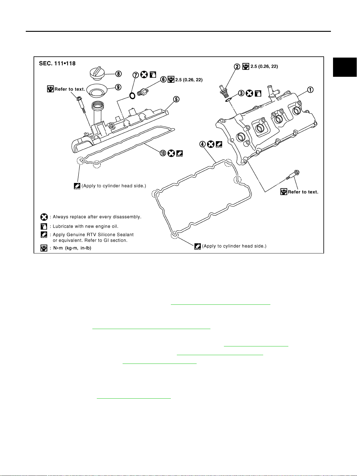
ROCKER COVER
EM-193
[VK45DE]
C
D
E
F
G
H
I
J
K
L
M
A
EM
Revision: 2004 November 2004 FX35/FX45
ROCKER COVER PFP:13264
Removal and Installation ABS006II
REMOVAL
1. Remove engine cover with power tool. Refer to EM-168, "ENGINE ROOM COVER" .
2. Refer to the following for incidental works related to left bank.
a. Remove air duct (inlet), air cleaner case and mass air flow sensor assembly, air duct and resonator
assembly. Refer to EM-172, "
AIR CLEANER AND AIR DUCT" .
b. Move harness on upper rocker cover and its peripheral aside.
c. Remove harness brackets from camshaft bracket (No. 6). Refer to EM-208, "
CAMSHAFT" .
d. Remove electric throttle control actuator. Refer to EM-174, "
INTAKE MANIFOLD" .
e. Remove ignition coil. Refer to EM-185, "
IGNITION COIL" .
f. Remove PCV hose from PCV valve.
3. Refer to the following for incidental works related to right bank.
a. Move harness on upper rocker cover and its peripheral aside.
b. Remove ignition coil EM-185, "
IGNITION COIL" .
c. Remove PCV hose from PCV valve.
1. Rocker cover (left bank) 2. PCV valve 3. O-ring
4. Rocker cover gasket (left bank) 5. Rocker cover (right bank) 6. PCV valve
7. O-ring 8. Oil filler cap 9. Oil catcher
10. Rocker cover gasket (right bank)
PBIC2353E
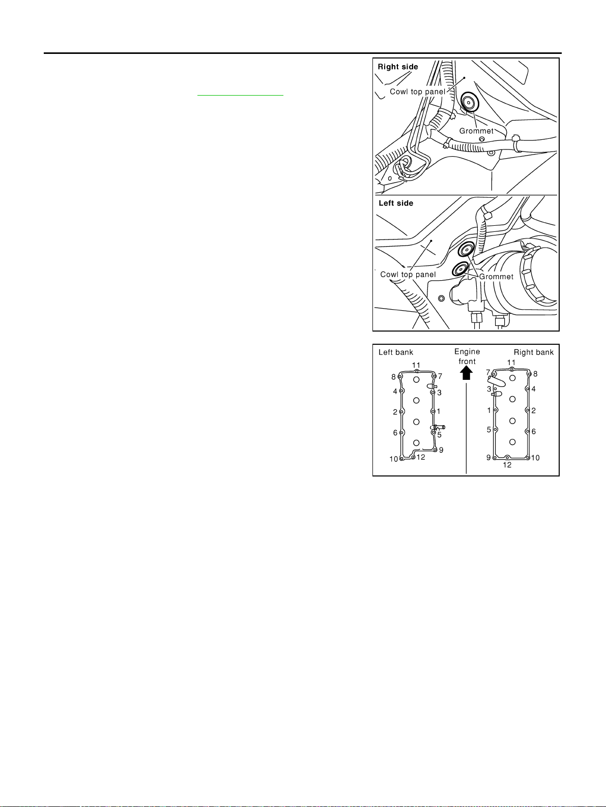
EM-194
[VK45DE]
ROCKER COVER
Revision: 2004 November 2004 FX35/FX45
4. Remove grommets from right and left cowl top panel.
● Remove right side grommet as follows:
– Remove battery. Refer to SC-4, "BATTERY" .
– Remove battery tray.
– Remove grommet.
5. Loosen bolts in reverse order as shown in the figure.
CAUTION:
Do not hold oil filler neck (right bank) not to damage it.
NOTE:
Loosen No. 10 bolt of the right bank and No. 10 and No. 12 bolts
of the left bank from cowl top panel hole with using tool.
6. Use scraper to remove all traces of liquid gasket from cylinder head and camshaft bracket.
PBIC2339E
PBIC0027E
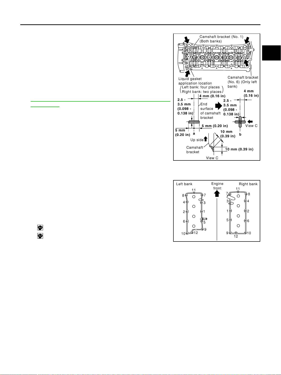
ROCKER COVER
EM-195
[VK45DE]
C
D
E
F
G
H
I
J
K
L
M
A
EM
Revision: 2004 November 2004 FX35/FX45
INSTALLATION
1. Apply liquid gasket to joint part of cylinder head and camshaft
bracket as follows:
NOTE:
The figure shows an example of left bank side [zoomed in
shows camshaft bracket (No. 1)]. Apply only to camshaft bracket
(No. 1) for right bank side.
a. Refer to the figure “a” to apply liquid gasket to joint part of cam-
shaft bracket (both No. 1 and No. 6) and cylinder head.
b. Refer to the figure “b” to apply liquid gasket in 90 degrees to the
figure “a”.
Use Genuine RTV Silicone Sealant or equivalent. Refer to
GI-48, "
RECOMMENDED CHEMICAL PRODUCTS AND
SEALANTS" .
2. Install rocker cover.
● Check if rocker cover gasket is not dropped from installation groove of rocker cover.
3. Tighten bolts in two steps separately in numerical order as
shown in the figure.
CAUTION:
Do not hold oil filler neck (right bank) not to damage it.
NOTE:
Tighten No. 10 bolt of the right bank and No. 10 and No. 12 bolts
of the left bank from cowl top panel hole with using tool.
4. Install in the reverse order of removal after this step.
PBIC2444E
1st step : 2.0 N·m (0.2 kg-m, 18 in-lb)
2nd step : 8.3 N·m (0.85 kg-m, 73 in-lb)
PBIC0027E
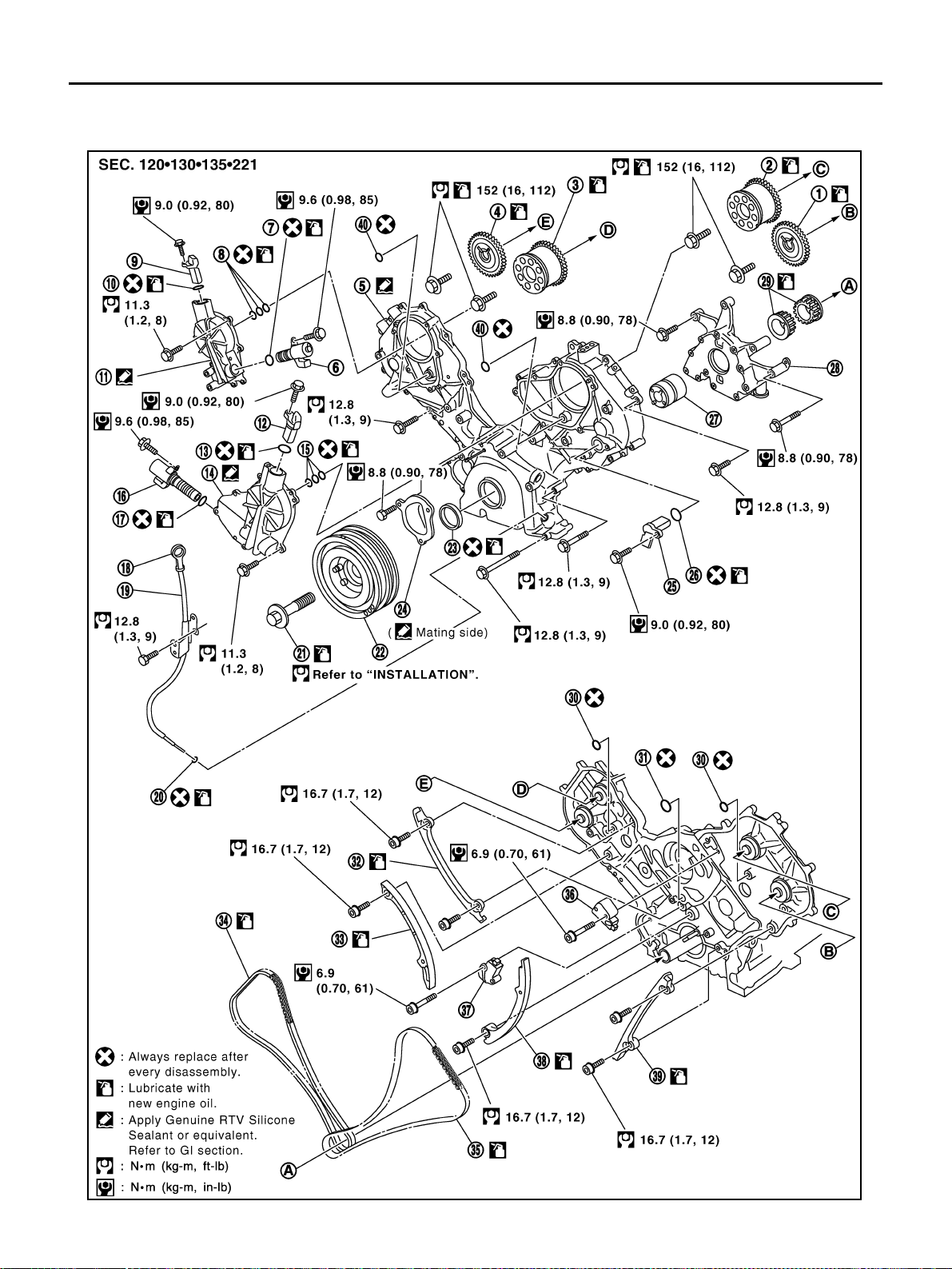
EM-196
[VK45DE]
TIMING CHAIN
Revision: 2004 November 2004 FX35/FX45
TIMING CHAIN PFP:13028
Removal and Installation ABS006IJ
PBIC2340E
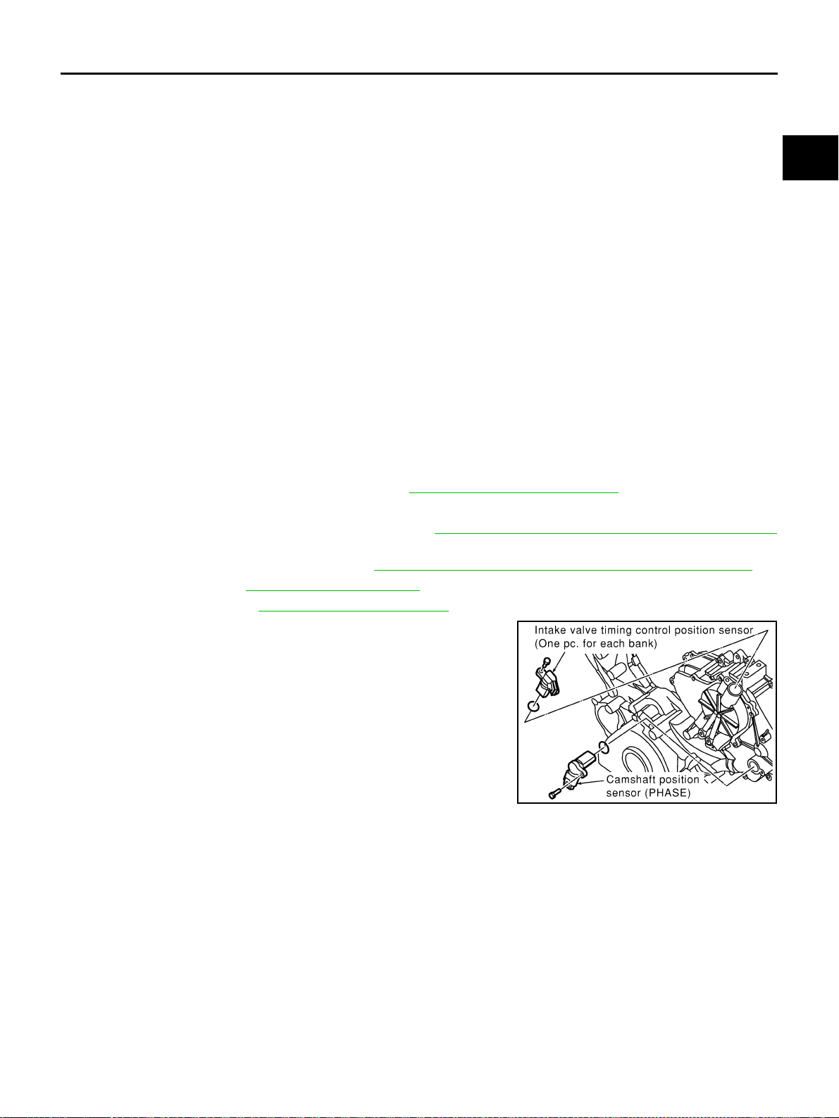
TIMING CHAIN
EM-197
[VK45DE]
C
D
E
F
G
H
I
J
K
L
M
A
EM
Revision: 2004 November 2004 FX35/FX45
REMOVAL
1. Remove engine assembly from vehicle. Refer to EM-236, "ENGINE ASSEMBLY" .
2. Remove the following components and related parts:
● Drive belt auto tensioner and idler pulley; Refer to EM-171, "Drive Belt Auto Tensioner and Idler Pulley"
.
● Thermostat housing and hoses; Refer to CO-51, "THERMOSTAT AND WATER CONTROL VALVE" .
● Ignition coil; Refer to EM-185, "IGNITION COIL" .
● Rocker cover; Refer to EM-193, "ROCKER COVER" .
3. If necessary, remove intake valve timing control position sensor
(right and left bank) and camshaft position sensor (PHASE) from
intake valve timing control cover and front cover.
CAUTION:
● Handle carefully to avoid dropping and shocks.
● Do not disassemble.
4. If necessary, remove intake valve timing control solenoid valve from intake valve timing control cover.
CAUTION:
● Handle components and parts carefully to avoid dropping and shocks.
● Do not disassemble.
● Do not allow metal powder to adhere to magnetic part at sensor tip.
● Do not place sensors in a location where they are exposed to magnetism.
1. Camshaft sprocket (EXH) 2. Camshaft sprocket (INT) 3. Camshaft sprocket (INT)
4. Camshaft sprocket (EXH) 5. Front cover 6.
Intake valve timing control solenoid
valve (right bank)
7. O-ring 8. Seal ring 9.
Intake valve timing control position
sensor (right bank)
10. O-ring 11.
Intake valve timing control cover
(right bank)
12.
Intake valve timing control position
sensor (left bank)
13. O-ring 14.
Intake valve timing control cover (left
bank)
15. Seal ring
16.
Intake valve timing control solenoid
valve (left bank)
17. O-ring 18. Oil level gauge
19. Oil level gauge guide 20. O-ring 21. Crankshaft pulley bolt
22. Crankshaft pulley 23. Front oil seal 24. Chain tensioner cover
25. Camshaft position sensor (PHASE) 26. O-ring 27. Oil pump drive spacer
28. Oil pump assembly 29. Crankshaft sprocket 30. O-ring
31. O-ring 32.
Timing chain tension guide
(right bank)
33.
Timing chain slack guide
(right bank)
34. Timing chain (right bank) 35. Timing chain (left bank) 36. Chain tensioner (left bank)
37. Chain tensioner (right bank) 38.
Timing chain slack guide
(left bank)
39.
Timing chain tension guide
(left bank)
40. O-ring
PBIC0050E
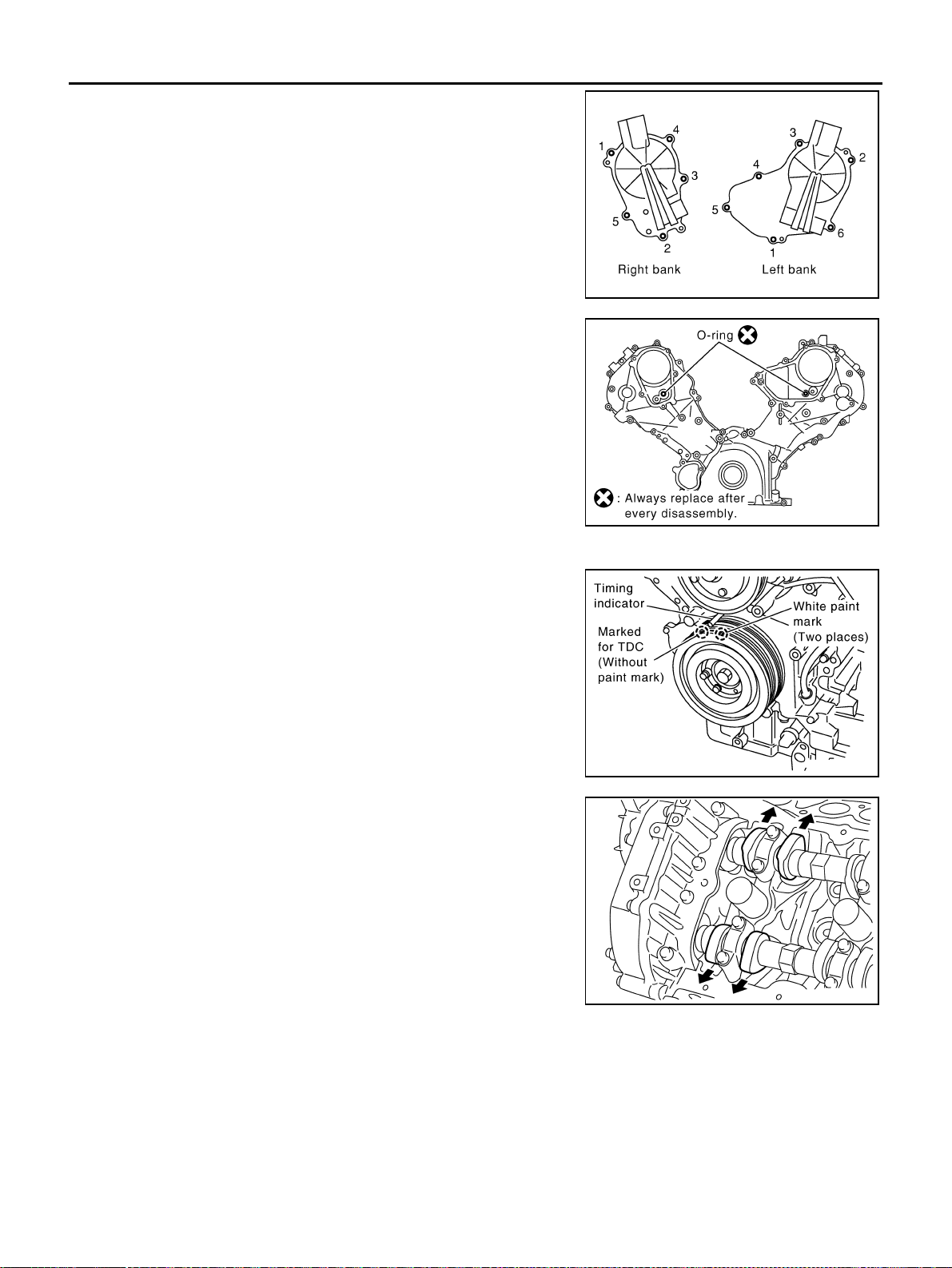
EM-198
[VK45DE]
TIMING CHAIN
Revision: 2004 November 2004 FX35/FX45
5. Remove intake valve timing control cover as follows:
a. Loosen and remove mounting bolts in the reverse order as
shown in the figure.
b. Use seal cutter [SST: KV10111100 (J37228)] or equivalent tool
to cut liquid gasket for removal.
CAUTION:
● Exercise care not to damage mating surfaces.
● Pull out cover keeping levelness without an angle, as
inner part of cover is engaged with the center of camshaft
sprocket (INT).
6. Remove O-rings from front cover.
7. Obtain No. 1 cylinder at TDC of its compression stroke as follows:
a. Rotate crankshaft pulley clockwise to align the TDC identifica-
tion notch (without paint mark) with timing indicator on front
cover.
b. Make sure that both intake and exhaust cam noses of No. 1 cyl-
inder (engine front side of left bank) are located as shown in the
figure.
● If not, turn crankshaft pulley one revolution (360 degrees) and
align as shown in the figure.
8. Remove crankshaft pulley as follows:
PBIC0051E
SBIA0374E
PBIC2341E
KBIA0400J
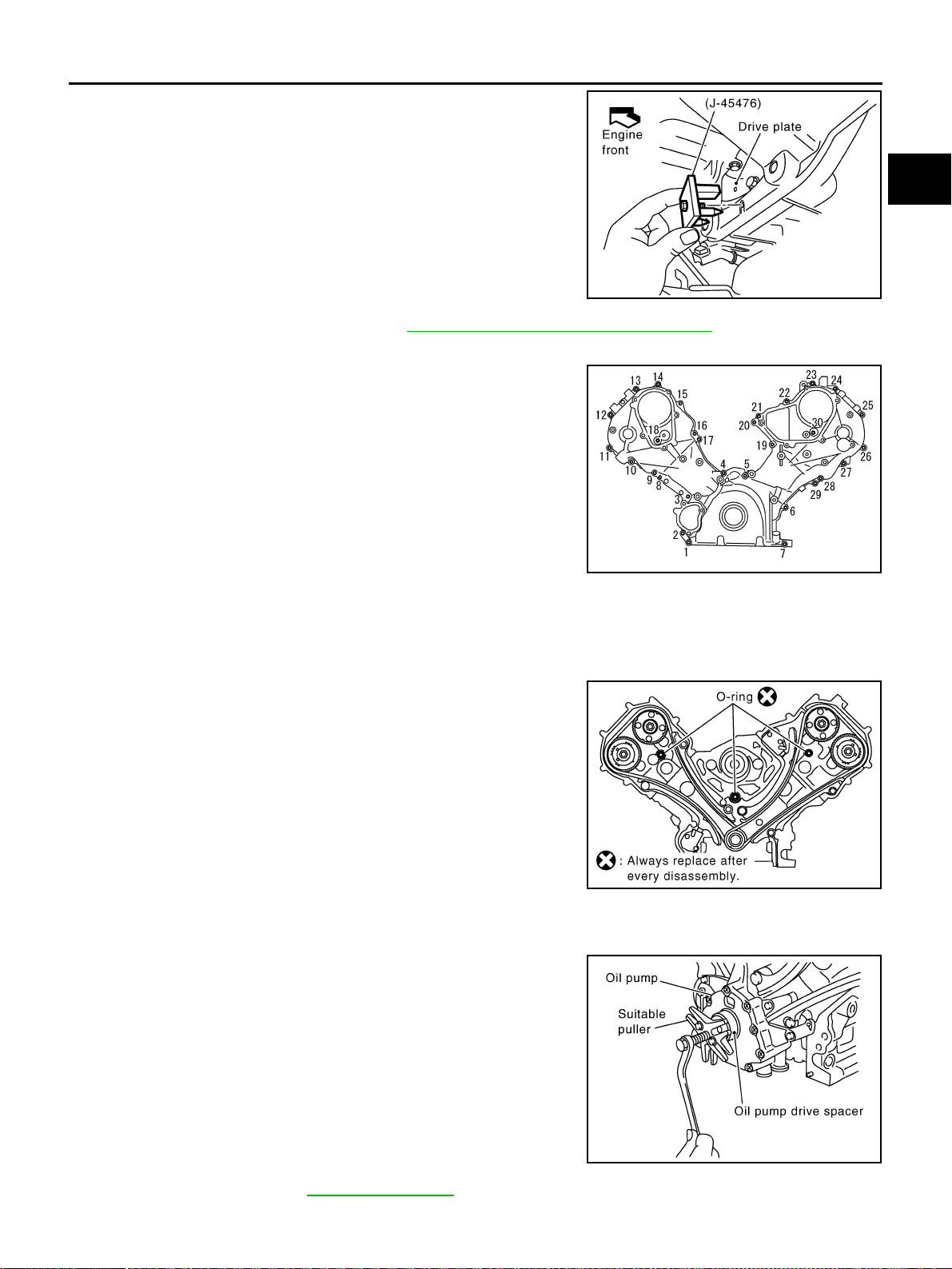
TIMING CHAIN
EM-199
[VK45DE]
C
D
E
F
G
H
I
J
K
L
M
A
EM
Revision: 2004 November 2004 FX35/FX45
a. Remove rear plate cover, and set ring gear stopper (SST).
b. Loosen crankshaft pulley bolt, and then pull crankshaft pulley
with both hands to remove it.
CAUTION:
● Do not remove crankshaft pulley bolt. Keep loosened
crankshaft pulley bolt in place to protect removed crank-
shaft pulley from dropping.
● Do not remove balance weight (inner hexagon bolt) at the
front of crankshaft pulley.
9. Remove oil pan and oil strainer. Refer to EM-181, "
OIL PAN AND OIL STRAINER" .
10. Remove front cover as follows:
a. Loosen mounting bolts in reverse order as shown in the figure.
b. Use seal cutter [SST: KV10111100 (J37228)] or equivalent tool
to cut liquid gasket for removal.
CAUTION:
● Exercise care not to damage mating surfaces.
● After removal, handle front cover carefully so it does not
tilt, cant, or warp under a load.
11. Remove front oil seal from front cover using suitable tool.
● Use flat-blade screwdriver for removal.
CAUTION:
Be careful not to damage front cover.
12. Remove O-rings from cylinder heads (right and left bank) and
cylinder block.
13. Remove chain tensioner cover from front cover.
● Use seal cutter [SST: KV10111100 (J37228)] or equivalent tool to cut liquid gasket for remove.
14. Remove oil pump drive spacer.
● Set bolts in the two bolt holes [M6 × pitch 1.0 mm (0.04 in)] on
front surface. Using suitable puller, pull oil pump drive spacer
off from crankshaft.
NOTE:
The dimension between the centers of the two bolt holes is 33
mm (1.30 in).
In the figure, a commercial steering puller is used.
15. Remove oil pump. Refer to LU-31, "
OIL PUMP" .
16. Remove chain tensioner (left bank) as follows:
PBIC1656E
KBIA0354J
SBIA0373E
PBIC2342E
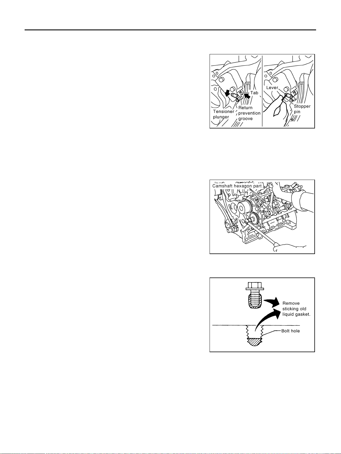
EM-200
[VK45DE]
TIMING CHAIN
Revision: 2004 November 2004 FX35/FX45
NOTE:
To remove timing chain and related parts, start with those on left bank. The procedure for removing parts
on right bank is omitted because it is the same as that for left bank.
a. Press tab in the direction of arrow (or turn lever in the direction
of arrow) to unlock the locking with the groove that stops ten-
sioner plunger from returning.
● Lightly press tensioner plunger to release the tension of
spring for this operation.
b. Push in tensioner plunger to align the hole on lever and that on
pump main body.
● Pushing in tensioner too far does not allow the holes to align.
Therefore, push in plunger to the degree at which the start of
stopper groove and tab engages.
c. Insert stopper pin [hard wire with approx. 0.5 mm (0.020 in)
diameter or similar tool] to fix plunger. With plunger fixed, remove chain tensioner.
17. Remove chain tension guide and timing chain slack guide.
18. Remove timing chain and crankshaft sprocket.
CAUTION:
After removing timing chain, do not turn crankshaft and camshaft separately, or valves will strike
the piston head.
19. With hexagonal part of camshaft locked with wrench, loosen
bolts securing camshaft sprocket to remove camshaft sprocket.
20. Perform same procedure as for left bank, remove timing chain and related parts on right side.
21. Use scraper to remove all traces of old liquid gasket from front cover and opposite mating surfaces.
● Remove oil liquid gasket from bolt hole and thread.
22. Use scraper to remove all trace of liquid gasket from chain tensioner cover and intake valve timing control
covers.
PBIC2343E
PBIC0030E
PBIC2084E
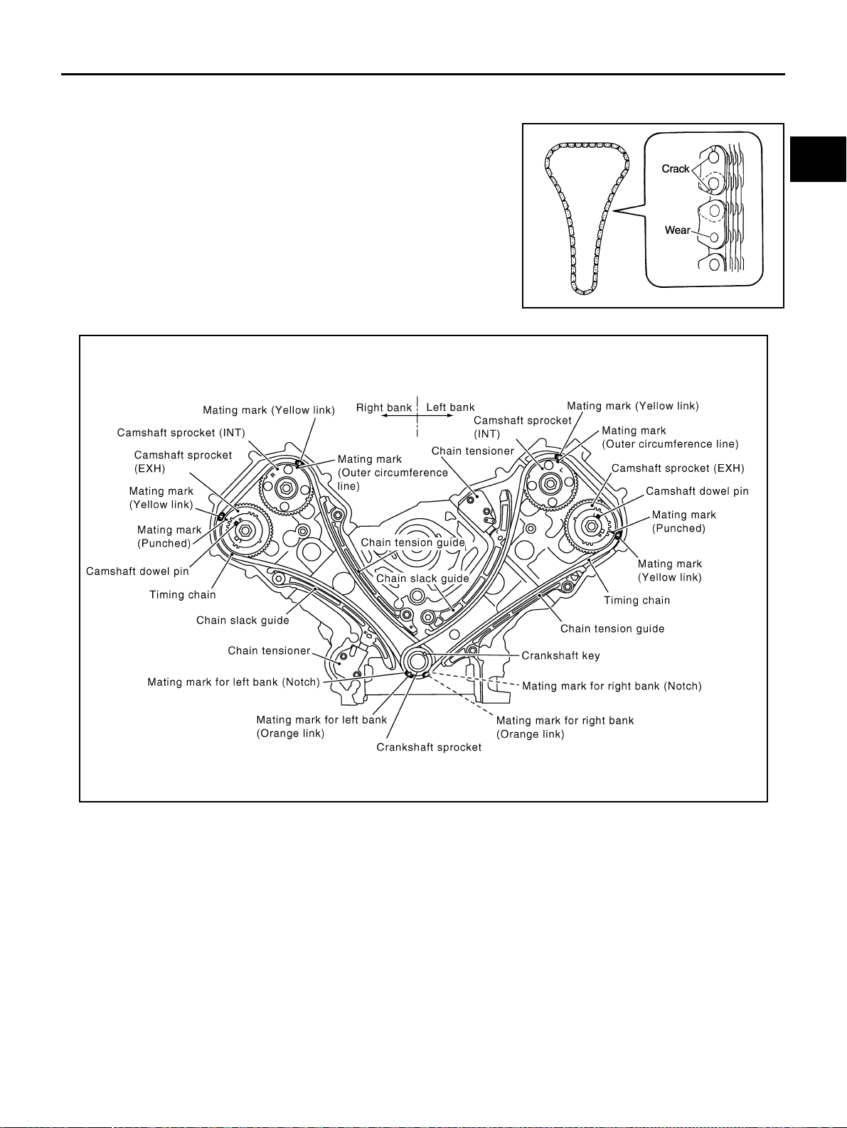
TIMING CHAIN
EM-201
[VK45DE]
C
D
E
F
G
H
I
J
K
L
M
A
EM
Revision: 2004 November 2004 FX35/FX45
INSPECTION AFTER REMOVAL
Timing Chain
Check tor cracks and any excessive wear at the roller links and link
plates. Replace timing chain as necessary.
INSTALLATION
NOTE:
● The above figure shows the relationship between the mating mark on each timing chain and that on the
corresponding sprocket, with the components installed.
● Parts with an identification mark (R or L) should be installed on the corresponding bank according to the
mark.
Parts with an identification mark:
– Camshaft sprocket (INT)
– Dowel pin groove of camshaft sprocket (EXH) (camshaft sprocket is same part both banks)
– Chain tension guide
– Chain slack guide
● Because of parallel manufacture, there are two types of mark (link colors) for timing chain.
● To install timing chain and related parts, start with those on right bank. The procedure for installing parts
on left bank is omitted because it is the same as that for installation on right bank.
PBIC0282E
PBIC2344E
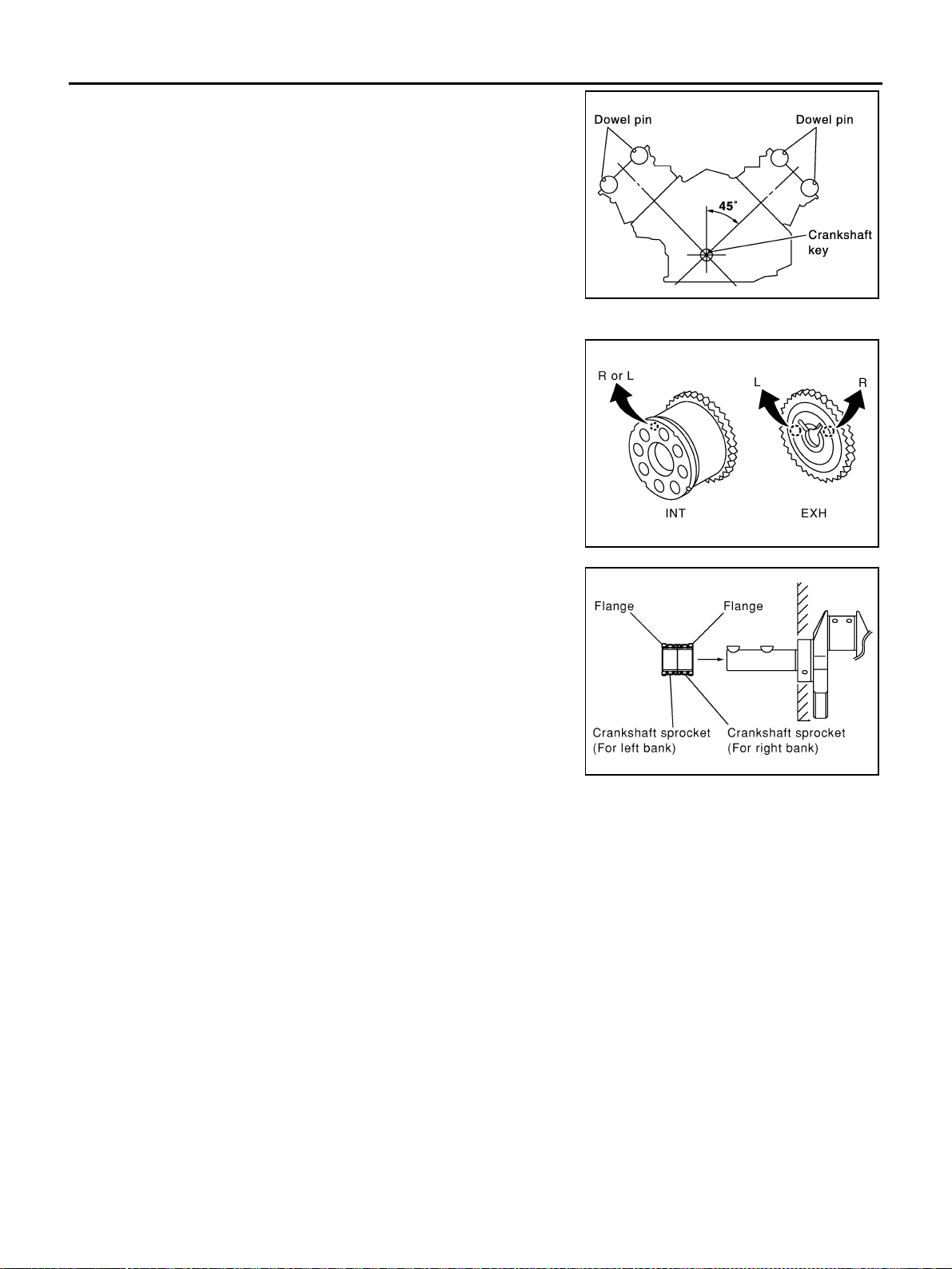
EM-202
[VK45DE]
TIMING CHAIN
Revision: 2004 November 2004 FX35/FX45
1. Make sure that crankshaft key and dowel pin of each camshaft
are located as shown in the figure. (No. 1 cylinder at compres-
sion TDC)
NOTE:
Though camshaft does not stop at the position as shown in the
figure, for the placement of cam nose, it is generally accepted
camshaft is placed for the same direction of the figure.
2. Install camshaft sprockets.
● Install onto correct side by checking with identification mark
on surface.
● Install camshaft sprocket (EXH) by selectively using the
groove of dowel pin according to the bank. (Common part
used for both banks.)
● Lock the hexagonal part of camshaft in the same procedure
as for removal, and tighten mounting bolts.
3. Install crankshaft sprockets for both banks.
● Install each crankshaft sprocket so that its flange side (the
larger diameter side without teeth) faces in the direction
shown in the figure.
NOTE:
The same parts are used but facing directions are different.
Camshaft dowel pin
: At cylinder head upper face side in each bank
Crankshaft key
: At cylinder head side of left bank
SBIA0356E
PBIC2345E
PBIC0057E
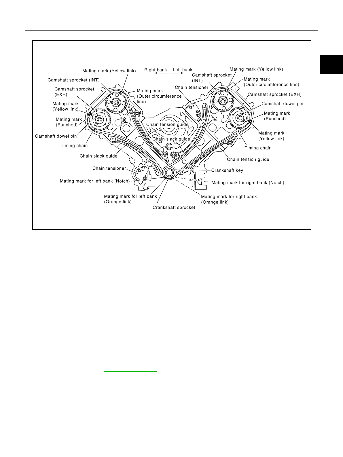
TIMING CHAIN
EM-203
[VK45DE]
C
D
E
F
G
H
I
J
K
L
M
A
EM
Revision: 2004 November 2004 FX35/FX45
4. Install timing chains and related parts.
● Align the mating mark on each sprocket and timing chain for installation.
CAUTION:
For the above reason, after the mating marks are aligned, keep them aligned by holding them
with a hand.
NOTE:
Before installing chain tensioner, it is possible to change the position of mating mark on timing chain for
that on each sprocket for alignment.
● Install slack guides and tension guides onto correct side by checking with identification mark on sur-
face.
● Install chain tensioner with plunger fixed as described in its removal.
CAUTION:
● Before and after the installation of chain tensioner, make sure that the mating mark on timing
chain is not out of alignment.
● After installing chain tensioner, remove stopper pin to release tensioner. Make sure tensioner
is released.
● To avoid chain-link skipping of timing chain, do not move crankshaft or camshafts until front
cover is installed.
5. Perform the same procedure as for right bank, install timing chain and related parts on left side.
6. Install oil pump. Refer to LU-31, "
OIL PUMP" .
PBIC2344E
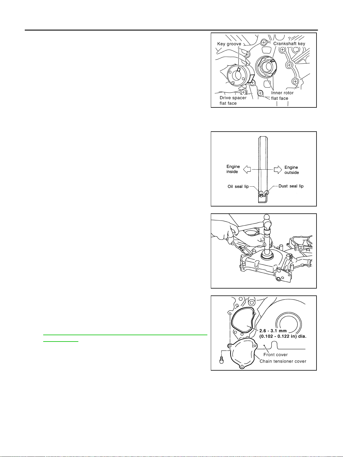
EM-204
[VK45DE]
TIMING CHAIN
Revision: 2004 November 2004 FX35/FX45
7. Install oil pump drive spacer as follows:
a. Insert oil pump drive spacer according to the directions of crank-
shaft key and the two flat surfaces of oil pump inner rotor.
● If the positional relationship does not allow the insertion,
rotate oil pump inner rotor with a finger to allow spacer.
b. After confirming that the position of each part is in correct condi-
tion to allow for spacer, force fit spacer by lightly tapping with
plastic hammer until it contacts and does not go further.
8. Install front oil seal on front cover.
● Apply new engine oil to both oil seal lip and dust seal lip.
● Install it so that each seal lip is oriented as shown in the fig-
ure.
CAUTION:
Be careful not to scratch or make burrs on circumference
of oil seal.
● Using suitable drift, press fit until the height of front oil seal is
level with the mounting surface.
● Make sure the garter spring is in position and seal lips not
inverted.
9. Install chain tensioner cover to front cover.
● Apply a continuous bead of liquid gasket with tube presser
[SST: WS39930000 ( — )] to front cover as shown in the
figure.
Use Genuine RTV Silicone Sealant or equivalent. Refer to
GI-48, "
RECOMMENDED CHEMICAL PRODUCTS AND
SEALANTS" .
10. Install front cover as follows:
PBIC0058E
SEM715A
Suitable drift
Outer diameter : 56 mm (2.20 in)
Inner diameter : 49 mm (1.93 in)
PBIC0059E
SBIA0372E
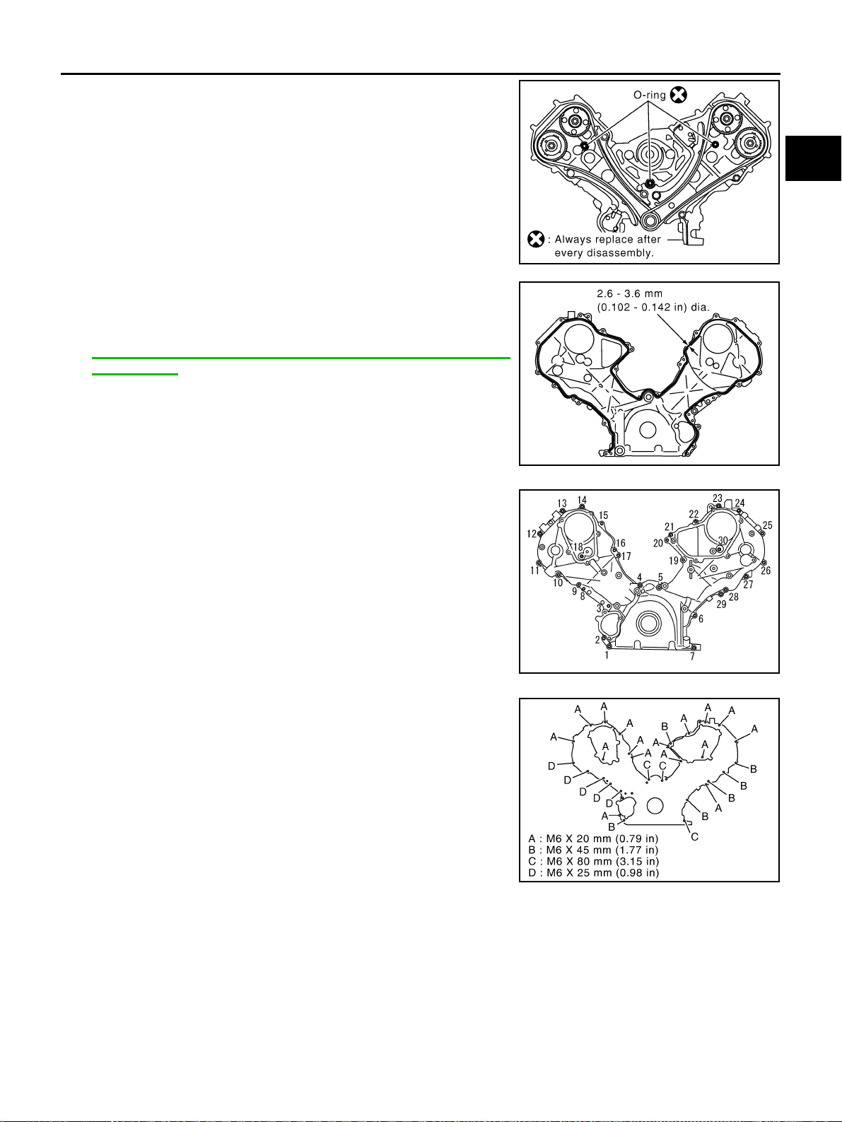
TIMING CHAIN
EM-205
[VK45DE]
C
D
E
F
G
H
I
J
K
L
M
A
EM
Revision: 2004 November 2004 FX35/FX45
a. Install new O-rings onto cylinder heads (right and left bank) and
cylinder block.
b. Apply a continuous bead of liquid gasket with tube presser
[SST: WS39930000 ( — )] to front cover as shown in the fig-
ure.
Use Genuine RTV Silicone Sealant or equivalent. Refer to
GI-48, "
RECOMMENDED CHEMICAL PRODUCTS AND
SEALANTS" .
c. make sure again that the mating marks on timing chain and that
on each sprocket are aligned. Then, install front cover.
CAUTION:
Be careful to avoid interference with the front end of oil
pump drive spacer. Such interference may damage front oil
seal.
d. Tighten mounting bolts in numerical order as shown in the fig-
ure.
● There are four type mounting bolts.
e. After all bolts are tightened, retighten them in numerical order as shown in the figure.
CAUTION:
Be sure to wipe off any excessive liquid gasket leaking onto surface mating with oil pan.
11. Install intake valve timing control cover as follows:
a. At the back of intake valve timing control cover, install new seal rings (three for each bank) to the area to
be inserted into camshaft sprocket (INT).
CAUTION:
Do not spread seal ring excessively to avoid breaks and deformation.
SBIA0373E
PBIC0062E
KBIA0354J
PBIC1681E
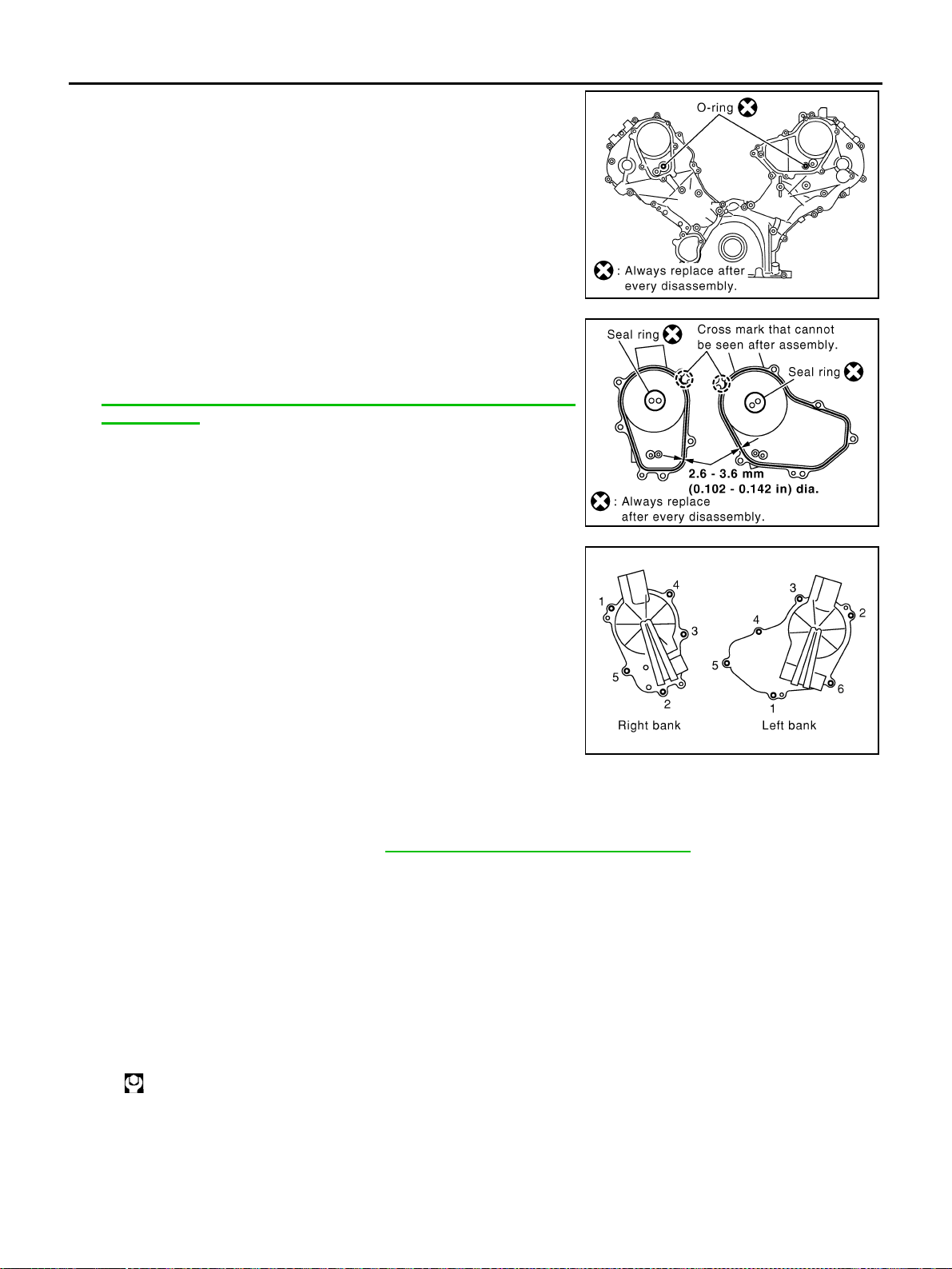
EM-206
[VK45DE]
TIMING CHAIN
Revision: 2004 November 2004 FX35/FX45
b. Install new O-rings on front cover.
c. Apply a continuous bead of liquid gasket with tube presser [SST:
WS3930000 ( — )] to intake valve timing control covers as
shown in the figure.
Use Genuine RTV Silicone Sealant or equivalent. Refer to
GI-48, "
RECOMMENDED CHEMICAL PRODUCTS AND
SEALANTS".
d. Tighten mounting bolts in numerical order as shown in the fig-
ure.
12. Install intake valve timing control position sensor, intake valve timing control solenoid valve and camshaft
position sensor (PHASE) to intake valve timing control cover and front cover if removed.
● Be sure to tighten bolts with flanges completely seated.
13. Install oil pan and oil strainer. Refer to EM-181, "
OIL PAN AND OIL STRAINER" .
14. Install crankshaft pulley as follows:
a. Fix crankshaft with ring gear stopper [SST: J-45476].
b. Install crankshaft pulley, taking care not to damage front oil seal.
● Install according to dowel pin of oil pump drive spacer.
● Lightly tapping its center with plastic hammer, insert pulley.
CAUTION:
Do not tap pulley on the side surface where belt is installed (outer circumference).
c. Apply engine oil onto threaded parts of crankshaft pulley bolt and seating area.
d. Tighten crankshaft pulley bolt.
e. Put a paint mark on crankshaft pulley aligning with angle mark on crankshaft pulley bolt.
SBIA0374E
SBIA0375E
PBIC0051E
: 93.1 N·m (9.5 kg-m, 69 ft-lb)
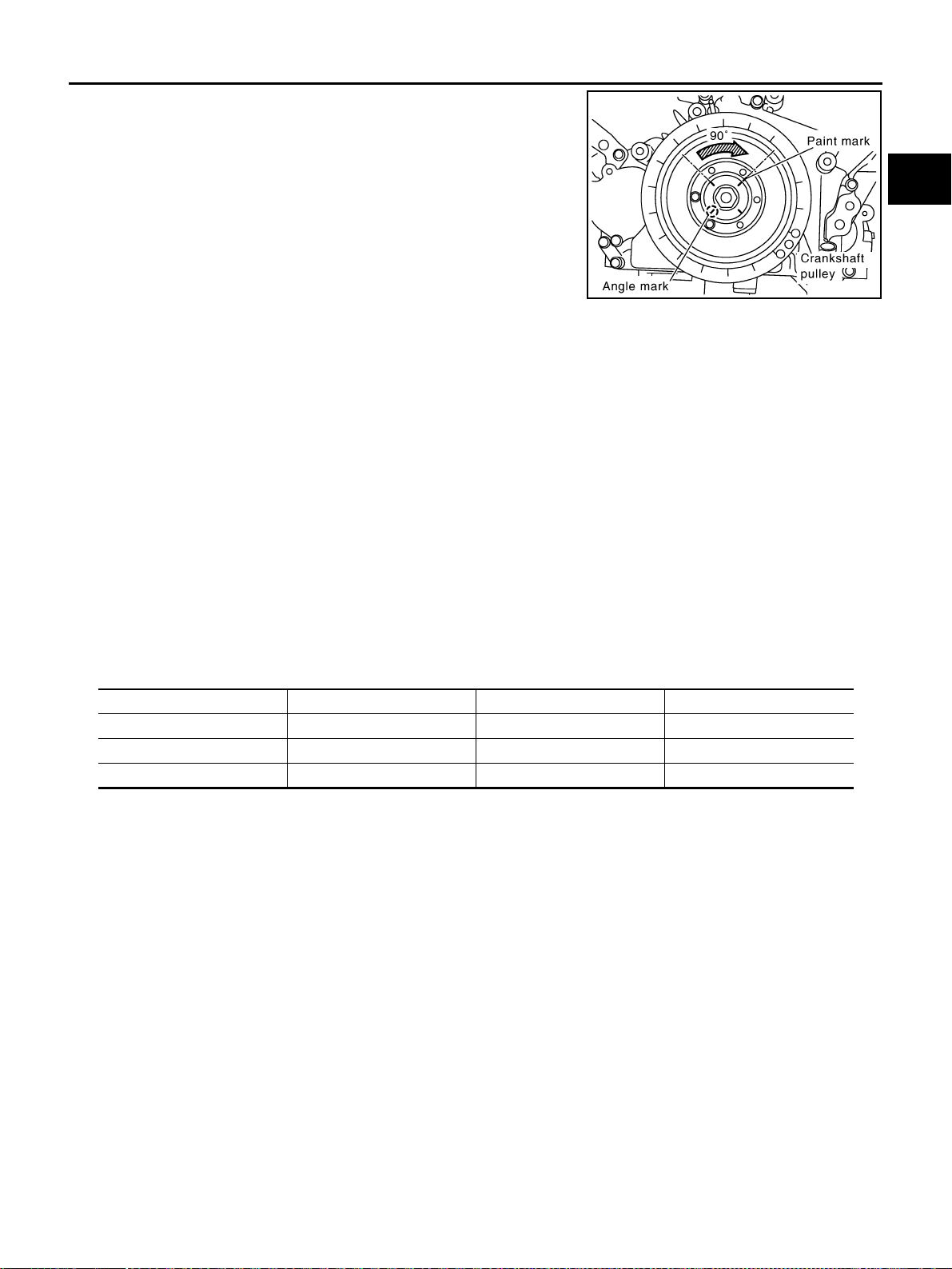
TIMING CHAIN
EM-207
[VK45DE]
C
D
E
F
G
H
I
J
K
L
M
A
EM
Revision: 2004 November 2004 FX35/FX45
f. Further tighten by 90 degrees. (Angle tightening)
● Check the tightening angle by referencing to the notches. The
angle between two notches is 90 degrees.
15. Rotate crankshaft pulley in normal direction (clockwise when viewed from engine front) to confirm it turns
smoothly.
16. Install in the reverse order of removal after this step.
NOTE:
If hydraulic pressure inside timing chain tensioner drops after removal/installation, slack in guide may gen-
erate a pounding noise during and just after engine start. However, this does not indicate an unusualness.
Noise will stop after hydraulic pressure rises.
INSPECTION AFTER INSTALLATION
● Before starting engine, check the levels of engine coolant, lubrications and working fluid. If less than
required quantity, fill to the specified level.
● Run engine to check for unusual noise and vibration.
● Warm up engine thoroughly to make sure there is no leakage of engine coolant, engine oil and working
fluid, fuel and exhaust gas.
● Bleed air from passages in pipes and tubes of applicable lines, such as in cooling system.
● After cooling down engine, again check amounts of engine coolant, engine oil and working fluid. Refill to
specified level, if necessary.
Summary of the inspection items:
PBIC2346E
Item Before starting engine Engine running After engine stopped
Engine coolant Level Leakage Level
Engine oil Level Leakage Level
Working fluid Level Leakage Level
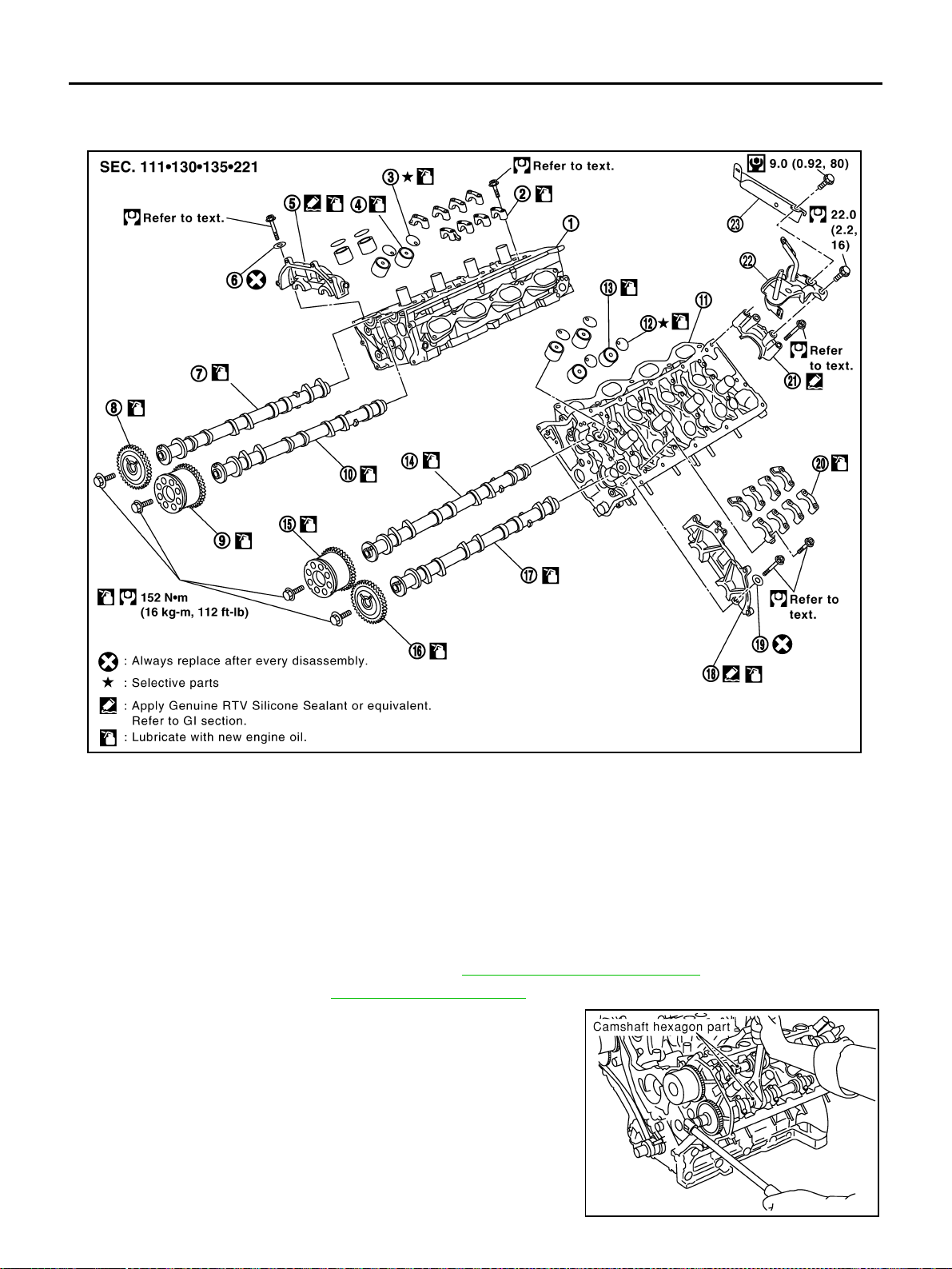
EM-208
[VK45DE]
CAMSHAFT
Revision: 2004 November 2004 FX35/FX45
CAMSHAFT PFP:13001
Removal and Installation ABS00FPG
REMOVAL
1. Remove engine assembly from vehicle. Refer to EM-236, "ENGINE ASSEMBLY" .
2. Remove timing chain. Refer to EM-196, "
TIMING CHAIN" .
3. With hexagonal part of camshaft locked with wrench, loosen
bolts securing camshaft sprocket to remove camshaft sprocket.
CAUTION:
After removing timing chain, do not turn crankshaft and
camshaft separately, or valves will strike the piston head.
1. Cylinder head (right bank) 2. Camshaft bracket (No. 2 to No. 5) 3. Adjusting shim
4. Valve lifter 5. Camshaft bracket (No. 1) 6. Seal washer
7. Camshaft (EXH) 8. Camshaft sprocket (EXH) 9. Camshaft sprocket (INT)
10. Camshaft (INT) 11. Cylinder head (left bank) 12. Adjusting shim
13. Valve lifter 14. Camshaft (INT) 15. Camshaft sprocket (INT)
16. Camshaft sprocket (EXH) 17. Camshaft (EXH) 18. Camshaft bracket (No. 1)
19. Seal washer 20. Camshaft bracket (No. 2 to No. 5) 21. Camshaft bracket (No. 6)
22. Harness bracket 23. Harness bracket
PBIC2354E
PBIC0030E
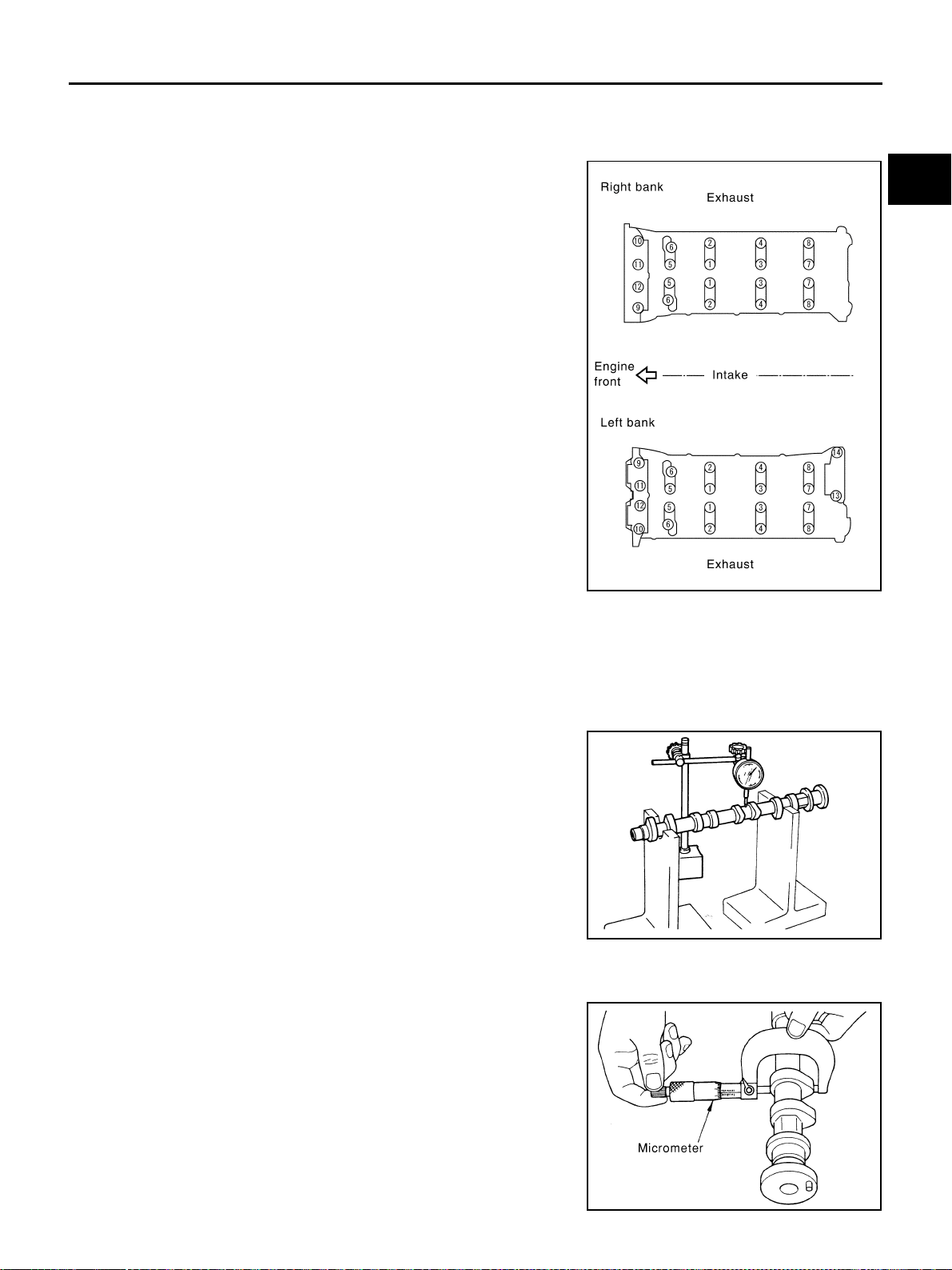
CAMSHAFT
EM-209
[VK45DE]
C
D
E
F
G
H
I
J
K
L
M
A
EM
Revision: 2004 November 2004 FX35/FX45
4. Remove intake and exhaust camshaft brackets.
● Mark camshafts, camshaft brackets and bolts so placed in the same position and direction for installa-
tion.
● Equally loosen camshaft brackets and bolts in several steps in
reverse order as shown in the figure.
● Lightly tapping with plastic hammer, remove camshaft bracket
(No. 1) and camshaft bracket (No. 6).
NOTE:
The bottom surface of each bracket will be stuck to cylinder
head because of liquid gasket.
5. Remove camshaft.
6. Remove adjusting shim and valve lifter if necessary.
● Identify installation positions, and store them without mixing them up.
INSPECTION AFTER REMOVAL
Camshaft Runout
1. Put V-block on precise flat table, and support No. 2 and No. 5
journal of camshaft.
CAUTION:
Do not support journal No. 1 (on the side of camshaft
sprocket) because it has a different diameter from the other
three locations.
2. Set dial indicator vertically to No. 3 journal.
3. Turn camshaft to one direction with hands, and measure cam-
shaft runout on dial indicator. (Total indicator reading)
4. If it exceeds the limit, replace camshaft.
Camshaft Cam Height
1. Measure camshaft cam height with micrometer.
2. If wear is beyond the limit, replace camshaft.
PBIC0031E
Limit : 0.02 mm (0.0008 in) PBIC2499E
Standard cam height
Intake : 44.865 - 45.055 mm (1.7663 - 1.7738 in)
Exhaust : 43.925 - 44.115 mm (1.7293 - 1.7368 in)
Cam wear limit
: 0.2 mm (0.008 in)
PBIC0039E
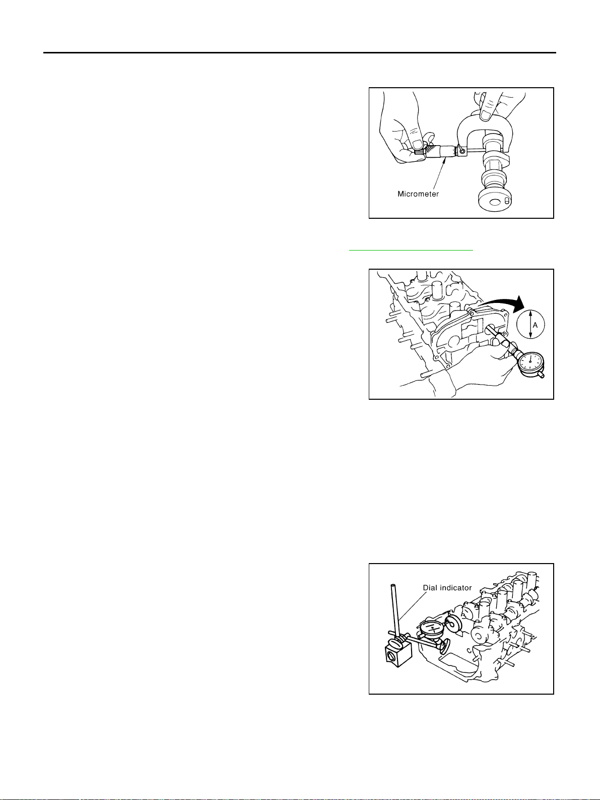
EM-210
[VK45DE]
CAMSHAFT
Revision: 2004 November 2004 FX35/FX45
Camshaft Journal Oil Clearance
CAMSHAFT JOURNAL DIAMETER
● Measure outer diameter of camshaft journal with micrometer.
CAMSHAFT BRACKET INNER DIAMETER
● Tighten camshaft bracket bolt with specified torque. Refer to EM-212, "INSTALLATION" for the tighten-
ing procedure.
● Measure inner diameter “A” of camshaft bracket with bore
gauge.
CAMSHAFT JOURNAL OIL CLEARANCE
● (Oil clearance) = (Camshaft bracket inner diameter) – (Camshaft journal diameter).
● If out of the standard, replace either or both camshaft and cylinder head.
NOTE:
Camshaft brackets cannot be replaced as a single part, because it is machined together with cylinder
head. Replace whole cylinder head assembly.
Camshaft End Play
● Install dial indicator in thrust direction on front end of camshaft.
Measure end play of dial indicator when camshaft is moved for-
ward/backward (in direction to axis).
Standard:
No. 1 : 25.938 - 25.955 mm (1.0212 - 1.0218 in)
No. 2, 3, 4 : 25.953 - 25.970 mm (1.0218 - 1.0224 in)
PBIC0040E
Standard:
26.000 - 26.021 mm (1.0236 - 1.0244 in)
PBIC1645E
Standard:
No. 1 : 0.045 - 0.083 mm (0.0018 - 0.0033 in)
No. 2, 3, 4 : 0.030 - 0.068 mm (0.0012 - 0.0027 in)
Standard:
0.115 - 0.188 mm (0.0045 - 0.0074 in)
PBIC2446E
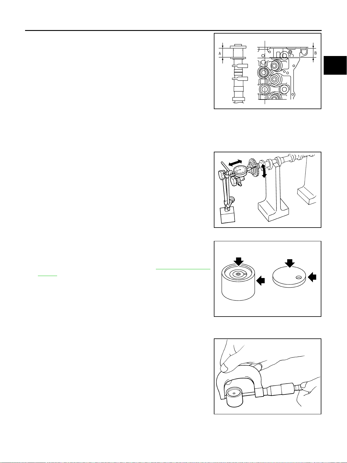
CAMSHAFT
EM-211
[VK45DE]
C
D
E
F
G
H
I
J
K
L
M
A
EM
Revision: 2004 November 2004 FX35/FX45
● Measure the following parts if out of the limit.
– Dimension “A” for camshaft No. 1 journal
– Dimension “B” for cylinder head No. 1 journal
● Refer to the standards above, and then replace camshaft and/or
cylinder head.
Camshaft Sprocket Runout
1. Put V-block on precise flat table, and support No. 2 and No. 5 journal of camshaft.
CAUTION:
Do not support journal No. 1 (on the side of camshaft sprocket) because it has a different diameter
from the other three locations.
2. Measure camshaft sprocket runout with dial indicator. (Total indi-
cator reading)
● If it exceeds the limit, replace camshaft sprocket.
Valve Lifter and Adjusting Shim
Check if surface of valve lifter and adjusting shim has any wear or
cracks.
● If anything above is found, replace valve lifter.
● When replacing adjusting shim, refer to EM-217, "ADJUST-
MENT" .
Valve Lifter Clearance
VALVE LIFTER OUTER DIAMETER
● Measure outer diameter of valve lifter with micrometer.
Standard : 30.500 - 30.548 mm (1.2008 - 1.2027 in)
Standard : 30.360 - 30.385 mm (1.1953 - 1.1963 in)
KBIA2426J
Limit : 0.15 mm (0.0059 in)
PBIC0930E
PBIC0231E
Standard : 33.965 - 33.975 mm (1.3372 - 1.3376 in)
SEM961E
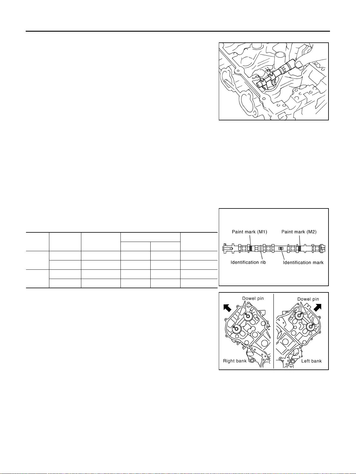
EM-212
[VK45DE]
CAMSHAFT
Revision: 2004 November 2004 FX35/FX45
VALVE LIFTER HOLE DIAMETER
● Measure inner diameter of valve lifter hole of cylinder head with
inside micrometer.
VALVE LIFTER CLEARANCE
● (Valve lifter clearance) = (Valve lifter hole diameter) – (Valve lifter outer diameter)
● If it exceeds the standard, referring to each standard of valve lifter outer diameter and valve lifter hole
diameter, replace either or both valve lifter and cylinder head.
INSTALLATION
1. Install valve lifters and adjusting shims if removed.
● Install it in the original position.
2. Install camshafts.
● Follow your identification marks made during removal, or fol-
low the identification marks that are present on new cam-
shafts for proper placement and direction.
● Install camshaft so that dowel pin on front end face are posi-
tioned as shown in the figure. (No. 1 cylinder TDC on its com-
pression stroke)
NOTE:
Though camshaft does not stop at the position as shown in
the figure, for the placement of cam nose, it is generally
accepted camshaft is placed for the same direction of the fig-
ure.
Standard : 34.000 - 34.016 mm (1.3386 - 1.3392 in)
SEM867E
Standard : 0.025 - 0.51 mm (0.0010 - 0.0020 in)
Bank INT/EXH
Identification
rib
Paint marks
Identification
mark
M1 M2
RH
INT Yes Blue No RH
EXH Yes No Orange RH
LH
INT No Blue No LH
EXH No No Orange LH
Camshaft dowel pin
: At cylinder head upper face side in each bank
PBIC2355E
SBIA0366E
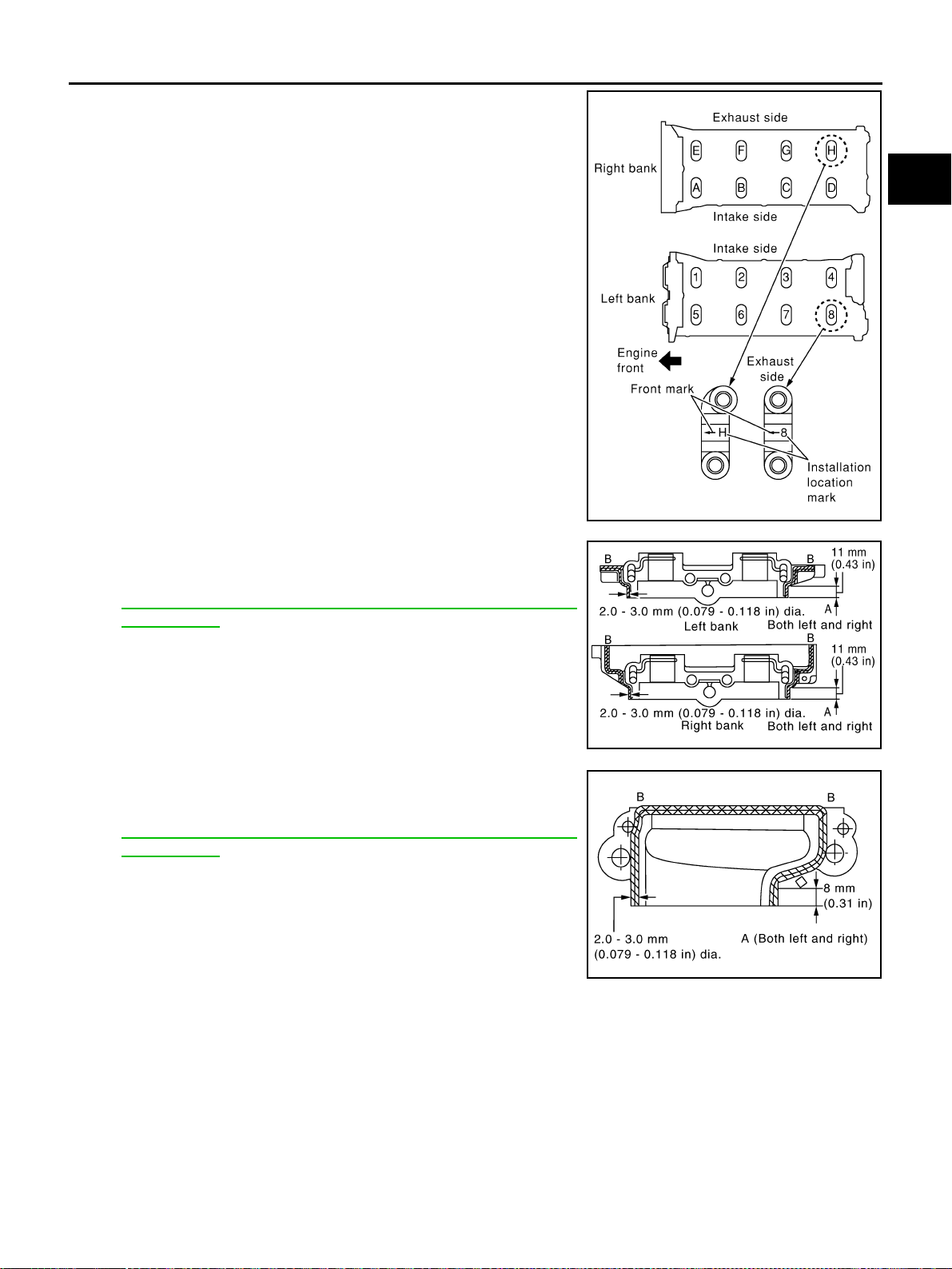
CAMSHAFT
EM-213
[VK45DE]
C
D
E
F
G
H
I
J
K
L
M
A
EM
Revision: 2004 November 2004 FX35/FX45
3. Install camshaft brackets.
● Remove foreign material completely from camshaft bracket
backside and from cylinder head installation face.
● Install by referring to installation location mark on upper sur-
face and front mark.
● Install so that installation location mark can be correctly read
when viewed from the side of left exhaust bank.
● Apply liquid gasket to mating surface of camshaft bracket (No.
1) as shown in the figure.
Use Genuine RTV Silicone Sealant or equivalent. Refer to
GI-48, "
RECOMMENDED CHEMICAL PRODUCTS AND
SEALANTS".
CAUTION:
● After installation, be sure to wipe off any excessive liq-
uid gasket leaking from part “A” and “B” (both on right
and left sides).
● Remove completely any excess of liquid gasket inside
bracket.
● Apply liquid gasket to mating surface of camshaft bracket (No.
6) on left bank intake as shown in the figure.
Use Genuine RTV Silicone Sealant or equivalent. Refer to
GI-48, "
RECOMMENDED CHEMICAL PRODUCTS AND
SEALANTS".
CAUTION:
● After installation, be sure to wipe off any excessive liq-
uid gasket leaking from part “A” and “B” (both on right
and left sides).
● Remove completely any excess of liquid gasket inside
bracket.
PBIC0034E
PBIC2356E
PBIC2357E
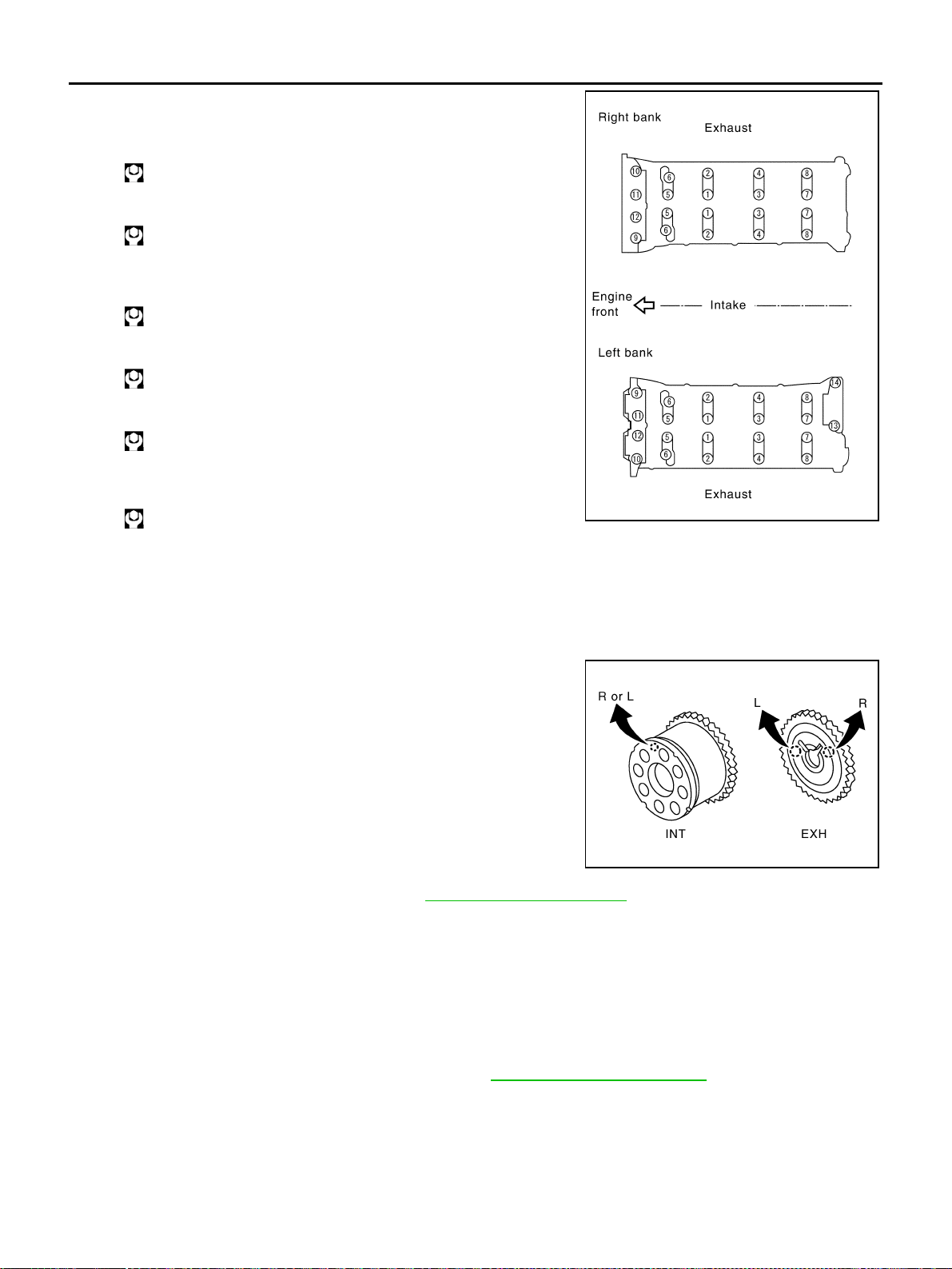
EM-214
[VK45DE]
CAMSHAFT
Revision: 2004 November 2004 FX35/FX45
4. Tighten camshaft bracket bolts in the following steps, in numeri-
cal order as shown in the figure.
a. Tighten No. 9 to 12 in numerical order as shown.
b. Tighten No. 1 to 8 in numerical order as shown.
c. Tighten No. 13 to 14 in numerical order as shown. (Left bank
only)
d. Tighten all bolts in numerical order as shown.
e. Tighten No. 1 to 12 in numerical order as shown.
f. Tighten No. 13 to 14 in numerical order as shown. (Left bank
only)
CAUTION:
After tightening mounting bolts of camshaft brackets, be sure to wipe off excessive liquid gasket
from the parts listed below.
● Mating surface of rocker cover
● Mating surface of front cover
5. Install camshaft sprockets.
● Install by checking with identification mark on surface.
● Instal camshaft sprocket (EXH) by selectively using the
groove of dowel pin according to the bank. (Common part
used for both banks.)
● Lock the hexagonal part of camshaft in the same way as for
removal, and tighten mounting bolts.
6. Check and adjust valve clearance. Refer to EM-214, "
Valve Clearance" .
7. Install in the reverse order of removal after this step.
Valve Clearance ABS006IL
INSPECTION
In cases of removing/installing or replacing camshaft and valve-related parts, or of unusual engine conditions
due to changes in valve clearance (found malfunctions during starting, idling or causing noise), perform
inspection as follows:
1. Warm up engine. Then stop it.
2. Remove rocker covers (right and left bank). Refer to EM-193, "
ROCKER COVER" .
3. Measure valve clearance as follows:
a. Set No. 1 cylinder at TDC of its compression stroke.
: 1.96 N·m (0.2 kg-m, 1 ft-lb)
: 1.96 N·m (0.2 kg-m, 1 ft-lb)
: 1.96 N·m (0.2 kg-m, 1 ft-lb)
: 5.88 N·m (0.6 kg-m, 4 ft-lb)
: 10.41 N·m (1.1 kg-m, 8 ft-lb)
: 31.35 N·m (3.2 kg-m, 23 ft-lb)
PBIC0031E
PBIC2345E
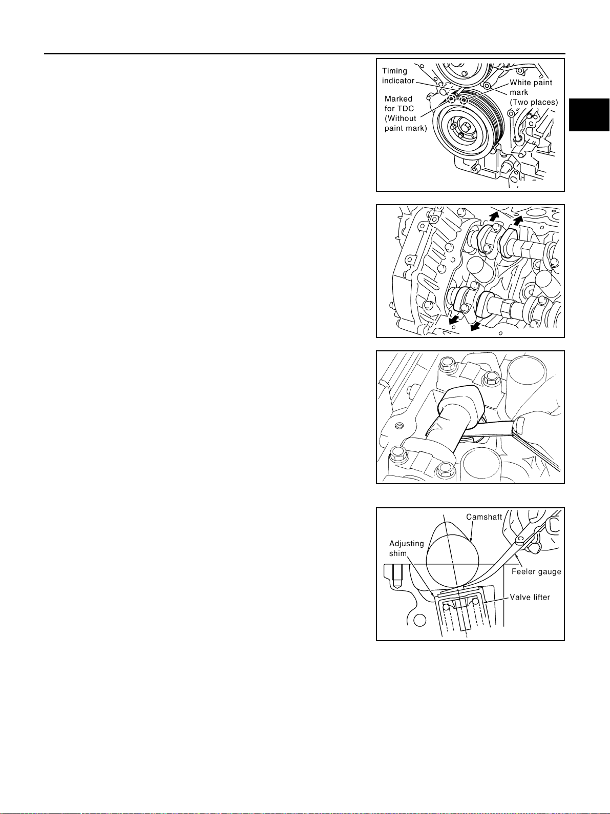
CAMSHAFT
EM-215
[VK45DE]
C
D
E
F
G
H
I
J
K
L
M
A
EM
Revision: 2004 November 2004 FX35/FX45
● Rotate crankshaft pulley in clockwise to align TDC identifica-
tion notch (without paint mark) with timing indicator on front
cover.
● Make sure that both intake and exhaust cam noses of No. 1
cylinder (engine front side of left bank) are located as shown
in the figure.
● If not, turn crankshaft one revolution (360 degrees) and align
as shown in the figure.
b. Measure valve clearance with feeler gauge.
*: Approximately 20°C (68°F) (Reference data)
CAUTION:
If inspection was carried out with cold engine, make sure
values with fully warmed up engine are still within specifi-
cations.
PBIC2341E
KBIA0400J
Valve clearance standard:
Hot
Intake : 0.304 - 0.416 mm (0.012 - 0.016 in)
Exhaust : 0.308 - 0.432 mm (0.012 - 0.017 in)
Cold*
Intake : 0.26 - 0.34 mm (0.010 - 0.013 in)
Exhaust : 0.29 - 0.37 mm (0.011 - 0.015 in)
SEM139D
PBIC0046E
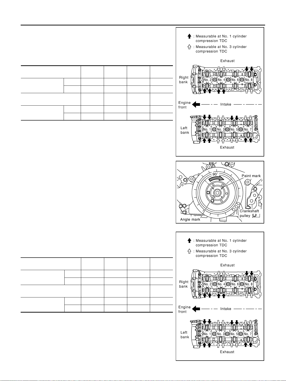
EM-216
[VK45DE]
CAMSHAFT
Revision: 2004 November 2004 FX35/FX45
● By referring to the figure, measure valve clearances at loca-
tions marked “×” as shown in the table below (locations indi-
cated with black arrow in figure).
NOTE:
Firing order 1-8-7-3-6-5-4-2
● No.1 cylinder compression TDC
c. Rotate crankshaft pulley clockwise (when view from engine
front) by 270 degrees from the position of No. 1 cylinder com-
pression TDC to align No. 3 cylinder at TDC of its compression
stroke.
NOTE:
Crankshaft pulley mounting bolt flange has a angle mark every
90 degrees. They can be used as a guide to rotation angle.
● By referring to the figure, measure valve clearances at loca-
tions marked “×” as shown in the table below (locations indi-
cated with white arrow in figure)
● No.3 cylinder compression TDC
Measuring position (right bank)
No. 2
CYL.
No. 4
CYL.
No. 6
CYL.
No. 8
CYL.
No. 1 cylinder at TDC
EXH ×
INT ××
Measuring position (left bank)
No. 1
CYL.
No. 3
CYL.
No. 5
CYL.
No. 7
CYL.
No. 1 cylinder at TDC
INT ××
EXH ××
PBIC2358E
PBIC2346E
Measuring position (right bank)
No. 2
CYL.
No. 4
CYL.
No. 6
CYL.
No. 8
CYL.
No. 3 cylinder at TDC
EXH ×
INT ×
Measuring position (left bank)
No. 1
CYL.
No. 3
CYL.
No. 5
CYL.
No. 7
CYL.
No. 3 cylinder at TDC
INT ××
EXH ××
PBIC2358E
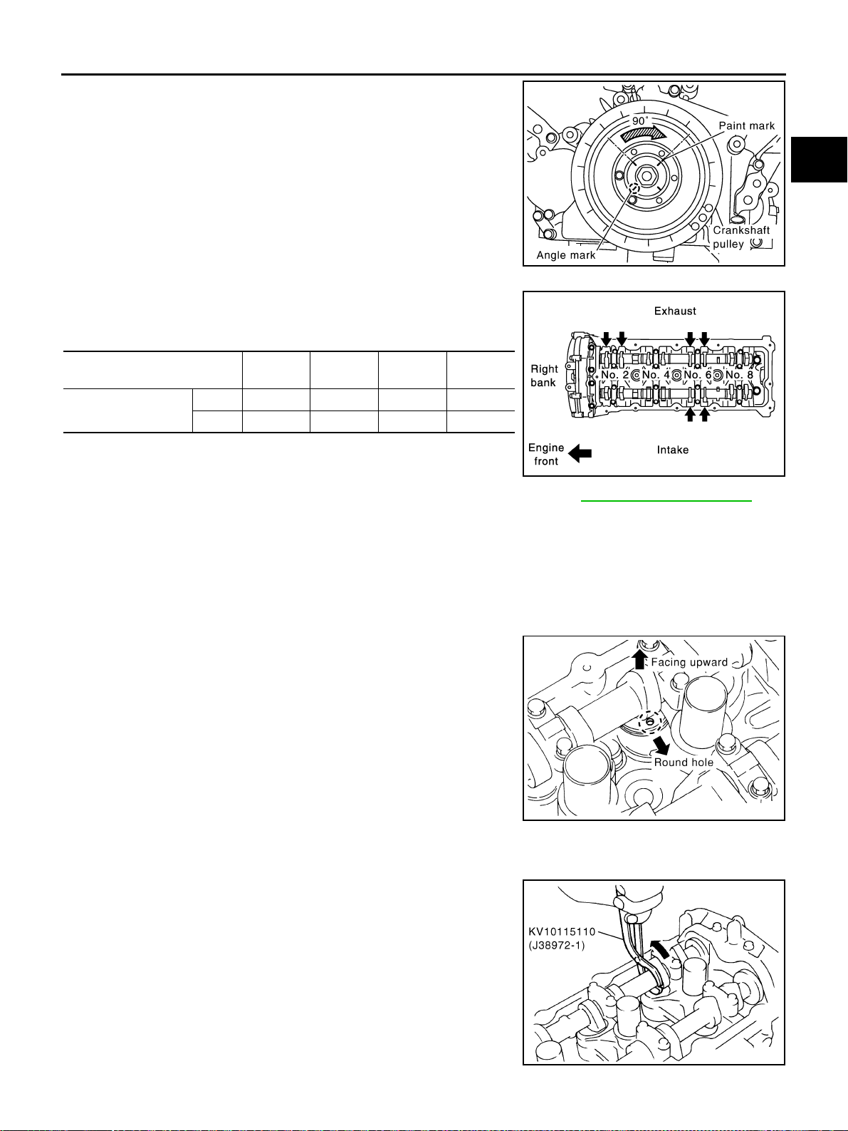
CAMSHAFT
EM-217
[VK45DE]
C
D
E
F
G
H
I
J
K
L
M
A
EM
Revision: 2004 November 2004 FX35/FX45
d. Rotate crankshaft pulley clockwise (when view from engine
front) by 90 degrees from the position of No. 3 cylinder compres-
sion TDC to align No. 6 cylinder at TDC of its compression
stroke.
● By referring to the figure, measure valve clearances at loca-
tions marked “×” as shown in the table below.
● No. 6 cylinder compression TDC
4. For measured value are out of the standard, perform adjustment. Refer to EM-217, "
ADJUSTMENT" .
ADJUSTMENT
CAUTION:
● Adjust valve clearance while engine is cold.
● After adjusting, make sure that the valve clearance is within the standard while engine is hot.
1. Thoroughly wipe off engine oil around adjusting shim using rag.
2. Rotate crankshaft to position cam nose on camshaft of valve that must be adjusted upward.
3. Using small screwdriver, turn the round hole of adjusting shim in
the direction of the arrow.
CAUTION:
perform (the above procedure) during camshaft do not con-
tact with adjusting shim.
4. Install lifter stopper [SST: 10115120 (J38972-2)] as follows:
a. Except exhaust side of No. 7 and No. 8 cylinder;
i. Place camshaft pliers (SST) around camshaft as shown in the
figure.
ii. Rotate camshaft pliers so that valve lifter is pushed down.
CAUTION:
Be careful not to damage cam surface, valve lifter and cylin-
der head with camshaft pliers.
PBIC2346E
Measuring position (right bank)
No. 2
CYL.
No. 4
CYL.
No. 6
CYL.
No. 8
CYL.
No. 6 cylinder at TDC
EXH × ×
INT ×
PBIC0824E
PBIC0047E
PBIC2276E
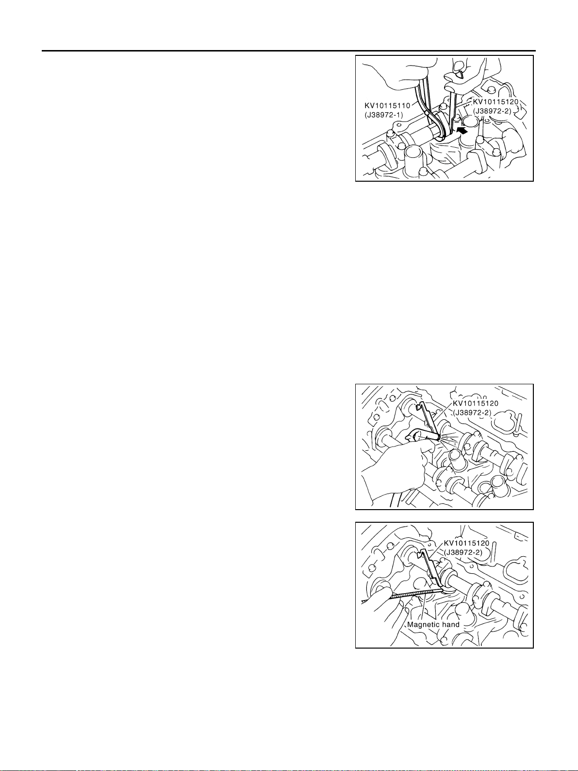
EM-218
[VK45DE]
CAMSHAFT
Revision: 2004 November 2004 FX35/FX45
iii. Place lifter stopper between camshaft and the edge of valve
lifter to retain valve lifter.
CAUTION:
● Lifter stopper must be placed as close to camshaft
bracket as possible.
● Be careful not to damage cam surface, valve lifter and
cylinder head with lifter stopper.
iv. Remove camshaft pliers.
CAUTION:
Camshaft pliers should be removed by rotating it slowly
because lifter stopper hits and damages journal portion by
rotating camshaft pliers quickly.
b. Exhaust side of No. 7 and No. 8 cylinder;
NOTE:
Exhaust side of No. 7 and No. 8 cylinder does not have space for installing camshaft pliers [SST:
KV10115110 (J38972-1)]. therefore, install lifter stopper [SST: KV10115120 (J38972-2)] according to the
following instructions.
i. Rotate crankshaft to press cam nose to the adjusting part of valve lifter.
ii. Place lifter stopper between camshaft and the edge of valve lifter to retain valve lifter.
CAUTION:
● Lifter stopper must be placed as close to camshaft bracket as possible.
● Be careful not to damage cam surface, valve lifter and cylinder head with lifter stopper.
iii. Rotate crankshaft slowly 180 degrees clockwise.
CAUTION:
Rotating crankshaft slowly because lifter stopper hits and damages journal portion by rotating
crankshaft quickly.
5. Blow air into the round hole to separate adjusting shim from
valve lifter.
CAUTION:
When blowing, use goggles to protect your eye.
6. Remove adjusting shim with magnetic hand.
7. Use the equation below to calculate adjusting shim thickness for replacement.
PBIC1565E
PBIC1566E
PBIC2359E

CAMSHAFT
EM-219
[VK45DE]
C
D
E
F
G
H
I
J
K
L
M
A
EM
Revision: 2004 November 2004 FX35/FX45
● Using micrometer determine thickness of removed shim with
measured at center.
● Calculate thickness of new adjusting shim so valve clearance comes within specified values (Cold
value).
Shims are available in 64 sizes from 2.32 mm (0.0913 in) to 2.95 mm (0.1161 in) in steps of 0.01
mm (0.0004 in).
● Thickness of new adjusting shim can be identified by stamp
marks on the reverse side (inside the cylinder).
8. Install new adjusting shim using suitable tool.
● Install with the surface on which the thickness is
stamped facing down.
9. Remove lifter stopper as follows:
a. Except exhaust side of No. 7 and No. 8 cylinder;
SEM145D
Valve lifter thickness calculation: t = t1 + (C1 – C2 )
t = Valve lifter thickness to be replaced
t
1 = Removed valve lifter thickness
C
1 = Measured valve clearance
C
2 = Standard valve clearance:
Intake : 0.30 mm (0.012 in)*
Exhaust : 0.33 mm (0.013 in)*
*: Approximately 20°C (68°F)
SEM873E
PBIC1568E
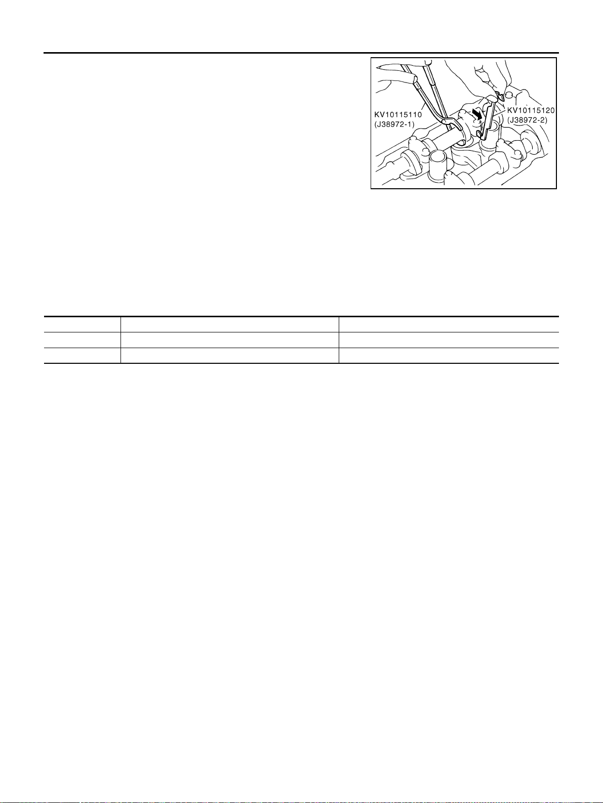
EM-220
[VK45DE]
CAMSHAFT
Revision: 2004 November 2004 FX35/FX45
i. Perform same procedure for removal, place camshaft pliers
(SST).
ii. Remove lifter stopper (SST).
iii. Remove camshaft pliers.
b. Exhaust side of No. 7 and No. 8 cylinder.
● Rotate crankshaft slowly 180 degrees clockwise. then remove lifter stopper.
10. Manually rotate crankshaft pulley a few turns.
11. Make sure that the valve clearance is within the standard.
12. Make sure again that the valve clearance for hot engine is within specifications by referring to the speci-
fied values.
Valve clearance:
Unit: mm (in)
*: Approximately 20°C (68°F)
PBIC1569E
Hot Cold* (reference data)
Intake 0.304 - 0.416 (0.012 - 0.016) 0.26 - 0.34 (0.010 - 0.013)
Exhaust 0.308 - 0.432 (0.012 - 0.017) 0.29 - 0.37 (0.011 - 0.015)
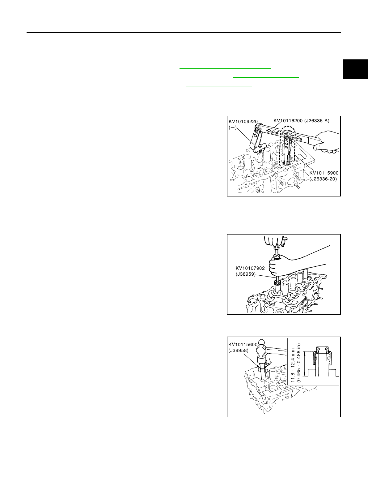
OIL SEAL
EM-221
[VK45DE]
C
D
E
F
G
H
I
J
K
L
M
A
EM
Revision: 2004 November 2004 FX35/FX45
OIL SEAL PFP:00100
Removal and Installation of Valve Oil Seal ABS006IM
REMOVAL
1. Remove engine assembly from vehicle. Refer to EM-236, "ENGINE ASSEMBLY" .
2. Remove camshaft relating to valve oil seal to be removed. Refer to EM-208, "
CAMSHAFT" .
3. Remove adjusting shims and valve lifters. Refer to EM-208, "
CAMSHAFT" .
● Identify installation positions, and store them without mixing them up.
4. Turn crankshaft until the cylinder requiring new oil seals is at TDC. This will prevent valve from dropping
into cylinder.
5. Remove valve collet.
● Compress valve spring with valve spring compressor, attach-
ment and adapter (SST). Remove valve collet with magnetic
hand.
CAUTION:
When working, take care not to damage valve lifter holes.
6. Remove valve spring retainer and valve spring.
CAUTION:
Do not remove valve spring seat from valve spring.
7. Remove valve oil seal using valve oil seal puller (SST).
INSTALLATION
1. Apply engine oil on new valve oil seal joint and seal lip.
2. Install valve oil seal.
● Install with valve oil seal drift (SST) to match dimension in the
figure.
3. Install in the reverse order of removal after this step.
PBIC2360E
PBIC0072E
PBIC0073E
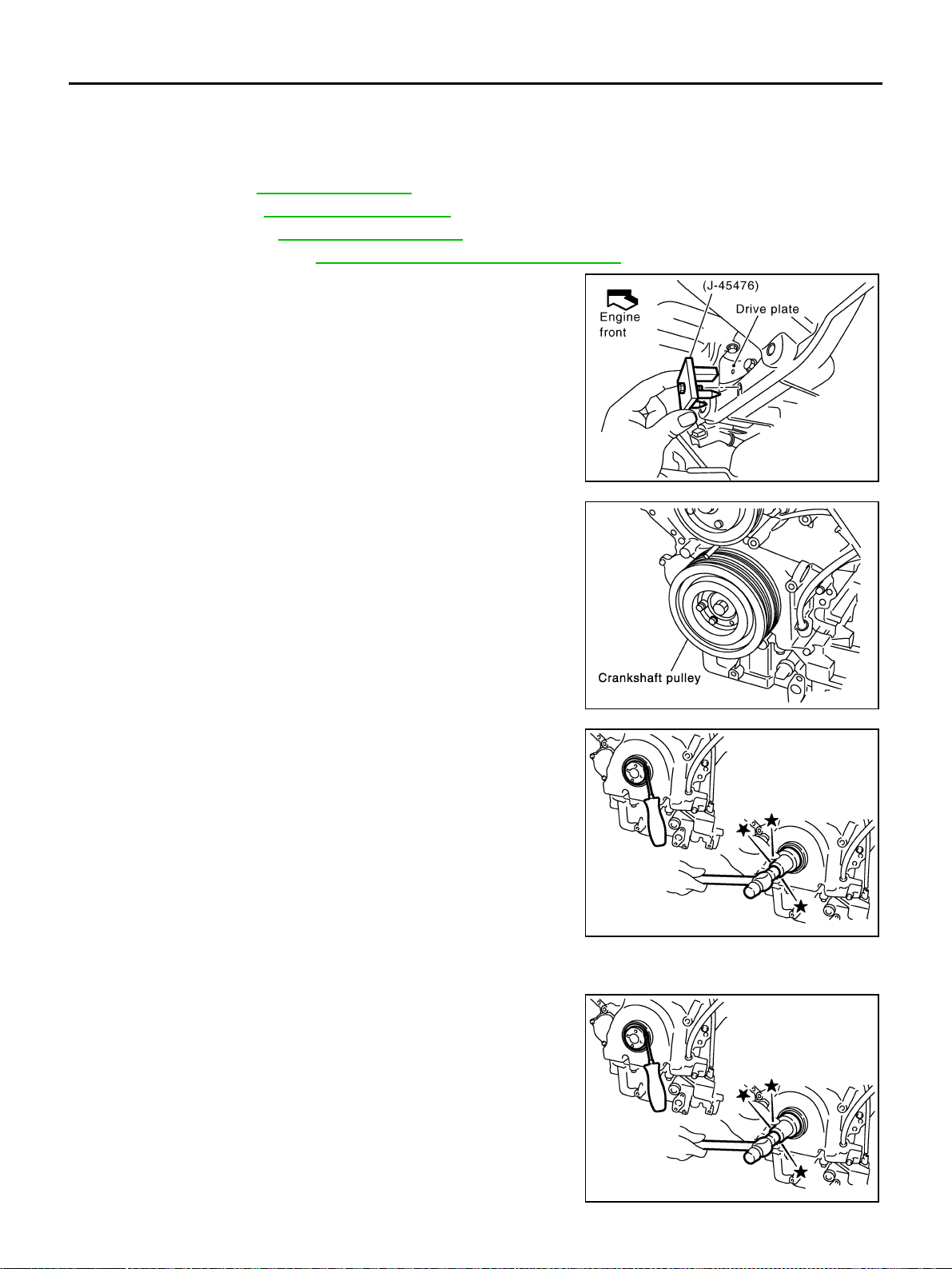
EM-222
[VK45DE]
OIL SEAL
Revision: 2004 November 2004 FX35/FX45
Removal and Installation of Front Oil Seal ABS006IN
REMOVAL
1. Remove the following parts:
● Front engine undercover
● Radiator; Refer to CO-39, "RADIATOR"
● Drive belt; Refer to EM-169, "DRIVE BELTS" .
● Cooling fan; Refer to CO-47, "COOLING FAN" .
● Rear plate cover; Refer to EM-181, "OIL PAN AND OIL STRAINER" .
2. Set ring gear stopper (SST).
3. Loosen crankshaft pulley bolt, and then pull crankshaft pulley
with both hands to remove it.
CAUTION:
● Do not remove crankshaft pulley bolt. Keep loosened
crankshaft pulley bolt in place to protect removed crank-
shaft pulley from dropping.
● Do not remove balance weight (inner hexagon bolt) at the
front of crankshaft pulley.
4. Remove front oil seal using suitable tool.
CAUTION:
Be careful not to damage front cover and oil pump drive
spacer.
INSTALLATION
1. Apply engine oil to both oil seal lip and dust seal lip.
2. Using suitable drift, press fit until the height of front oil seal is
level with the mounting surface.
PBIC1656E
SBIA0358E
SBIA0359E
Suitable drift
Outer diameter : 56 mm (2.20 in)
Inner diameter : 49 mm (1.93 in)
SBIA0359E
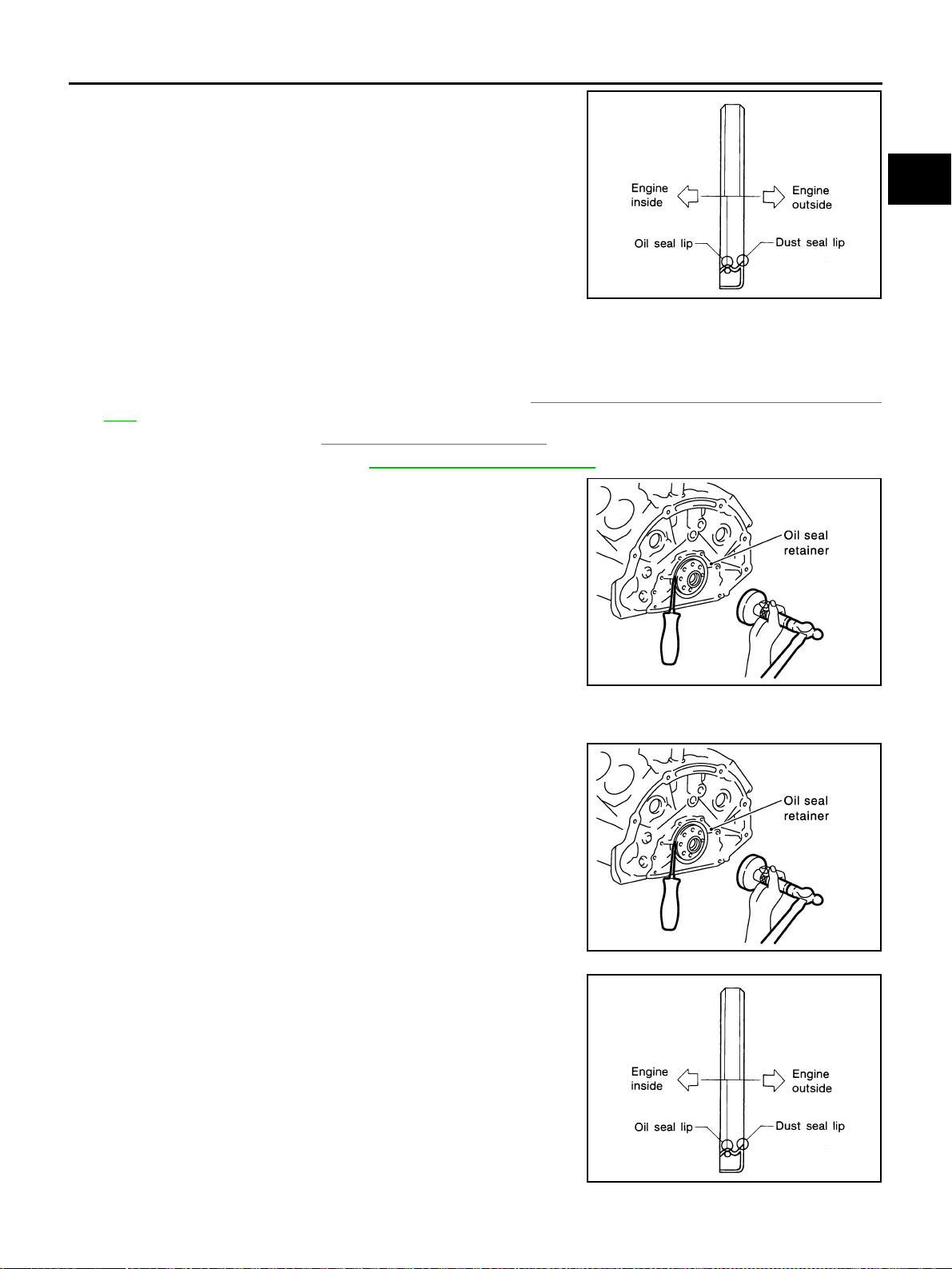
OIL SEAL
EM-223
[VK45DE]
C
D
E
F
G
H
I
J
K
L
M
A
EM
Revision: 2004 November 2004 FX35/FX45
● Install it so that each seal lip is oriented as shown in the fig-
ure.
CAUTION:
● Be careful not to damage front cover and oil pump drive
spacer.
● Press fit straight and avoid causing burrs or tilting oil
seal.
3. Install in the reverse order of removal after this step.
Removal and Installation of Rear Oil Seal ABS006IO
REMOVAL
1. Remove transmission (with transfer) assembly. Refer to AT-269, "Removal and Installation (AWD mod-
els)" .
a. Remove drive plate. Refer to EM-240, "
CYLINDER BLOCK" .
b. Remove engine rear plate. Refer to EM-240, "
CYLINDER BLOCK" .
2. Remove rear oil seal using suitable tool.
CAUTION:
Be careful not to damage crankshaft and oil seal retainer
surface.
INSTALLATION
1. Apply engine oil to both oil seal lip and dust seal lip.
2. Using suitable drift, press fit until the height of front oil seal is
level with the mounting surface.
● Install it so that each seal lip is oriented as shown in the fig-
ure.
CAUTION:
● Be careful not to damage crankshaft and rear oil seal
retainer.
● Press fit straight and avoid causing burrs or tilting oil
seal.
3. Install in the reverse order of removal after this step.
SEM715A
SBIA0360E
Suitable drift
Outer diameter : 102 mm (4.02 in)
Inner diameter : 86 mm (3.39 in)
SBIA0360E
SEM715A
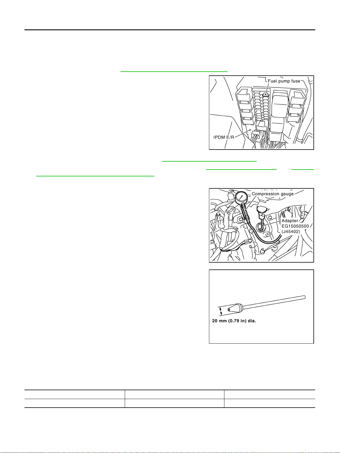
EM-224
[VK45DE]
CYLINDER HEAD
Revision: 2004 November 2004 FX35/FX45
CYLINDER HEAD PFP:11041
On-Vehicle Service ABS006IP
CHECKING COMPRESSION PRESSURE
1. Warm up engine thoroughly. Then, stop it.
2. Release fuel pressure. Refer to EC-700, "
FUEL PRESSURE RELEASE" .
a. Remove fuel pump fuse to avoid fuel injection during measure-
ment.
3. Remove engine cover with power tool. Refer to EM-168, "
ENGINE ROOM COVER" .
4. Remove ignition coil and spark plug from each cylinder. Refer to EM-185, "
IGNITION COIL" and EM-186,
"SPARK PLUG (PLATINUM-TIPPED TYPE)" .
5. Connect engine tachometer (not required in use of CONSULT-II).
6. Install compression gauge with adapter (SST or commercial ser-
vice tool) onto spark plug hole.
● Use compression gauge adapter (SST) which is required on
No. 7 and No. 8 cylinders.
● Use compression gauge adapter (if no SST is used) whose
picking up end inserted to spark plug hole is smaller than 20
mm (0.79 in) in diameter. Otherwise, it may be caught by cyl-
inder head during removal.
7. With accelerator pedal fully depressed, turn ignition switch to “START” for cranking. When the gauge
pointer stabilizes, read the compression pressure and engine rpm. Perform these steps to check each cyl-
inder.
Compression pressure:
Unit: kPa (kg/cm
2
, psi) /rpm
CAUTION:
Always use a fully changed battery to obtain specified engine speed.
PBIB1482E
PBIC1554E
SBIA0533E
Standard Minimum Deferential limit between cylinders
1,320 (13.5, 191) / 300 1,130 (11.5, 164) / 300 98 (1.0, 14) / 300
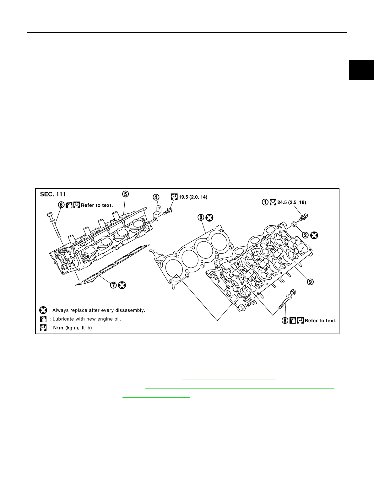
CYLINDER HEAD
EM-225
[VK45DE]
C
D
E
F
G
H
I
J
K
L
M
A
EM
Revision: 2004 November 2004 FX35/FX45
● If the engine speed is out of specified range, check battery liquid for proper gravity. Check engine
speed again with normal battery gravity.
● If compression pressure is below minimum value, check valve clearances and parts associated with
combustion chamber (valve, valve seat, piston, piston ring, cylinder bore, cylinder head, cylinder head
gasket). After the checking, measure compression pressure again.
● If some cylinders have low compression pressure, pour small amount of engine oil into the spark plug
hole of the cylinder to re-check it for compression.
– If the added engine oil improves the compression, piston rings may be worn out or damaged. Check the
piston rings and replace if necessary.
– If the compression pressure remains at low level despite the addition of engine oil, valves may be mal-
functioning. Check valves for damage. Replace valve or valve seat accordingly.
● If two adjacent cylinders have respectively low compression pressure and their compression remains
low even after the addition of engine oil, gaskets are leaking. In such a case, replace cylinder head gas-
kets.
8. After inspection is completed, install removed parts in the reverse order of removal.
9. Start engine, and make sure that engine runs smoothly.
10. Perform trouble diagnosis. If DTC appears, erase it. Refer to EC-726, "
TROUBLE DIAGNOSIS" .
Removal and Installation ABS006IQ
REMOVAL
1. Remove engine assembly from vehicle. Refer to EM-236, "ENGINE ASSEMBLY" .
2. Remove exhaust manifold. Refer to EM-178, "
EXHAUST MANIFOLD AND THREE WAY CATALYST" .
3. Remove camshaft. Refer to EM-208, "
CAMSHAFT" .
1. Engine coolant temperature sensor 2. Washer 3. Cylinder head gasket (left bank)
4. Harness bracket 5. Cylinder head (right bank) 6. Cylinder head bolt
7. Cylinder head gasket (right bank) 8. Cylinder head bolt 9. Cylinder head (left bank)
PBIC2407E
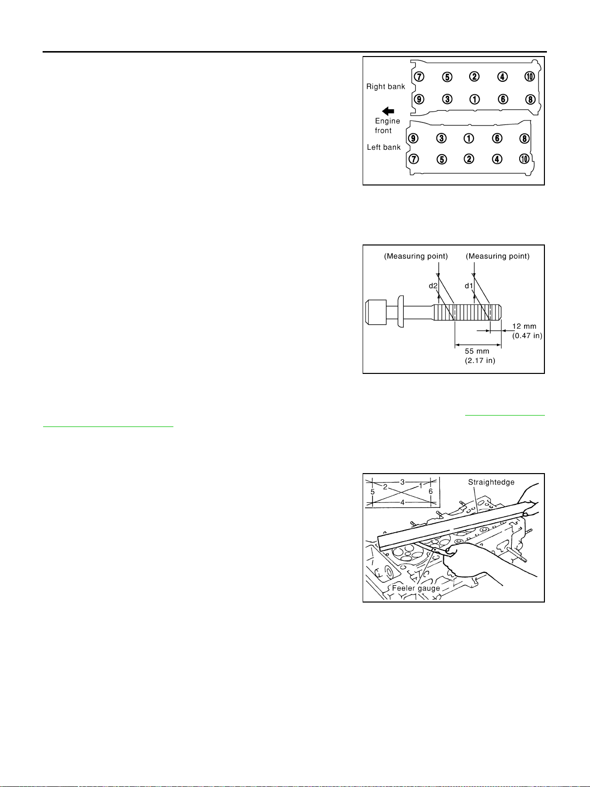
EM-226
[VK45DE]
CYLINDER HEAD
Revision: 2004 November 2004 FX35/FX45
4. Remove cylinder head bolts in reverse order as shown in the fig-
ure with cylinder head bolt wrench (commercial service tool).
5. Remove cylinder head gaskets.
INSPECTION AFTER REMOVAL
Cylinder Head Bolts Outer Diameter
● Cylinder head bolts are tightened by plastic zone tightening
method. Whenever the size difference between “d1” and “d2”
exceeds the limit, replace them with new one.
● If reduction of outer diameter appears in a position other than
“d2”, use it as “d2” point.
Cylinder Head Distortion
NOTE:
When performing this inspection, cylinder block distortion should be also checking. Refer to EM-259, "
CYLIN-
DER BLOCK DISTORTION" .
1. Using scraper, wipe off oil, scale, gasket, sealant and carbon deposits from surface of cylinder head.
CAUTION:
Do not allow gasket fragments to enter engine oil or engine coolant passages.
2. At each of several locations on bottom surface of cylinder head,
measure distortion in six directions.
● If it exceeds the limit, replace cylinder head.
INSTALLATION
1. Install cylinder head gasket.
2. Turn crankshaft until No. 1 piston is set at TDC.
PBIC0068E
Limit (“d1” - “d2”) : 0.18 mm (0.0071 in)
PBIC2361E
Limit : 0.1 mm (0.004 in)
PBIC0075E

CYLINDER HEAD
EM-227
[VK45DE]
C
D
E
F
G
H
I
J
K
L
M
A
EM
Revision: 2004 November 2004 FX35/FX45
● Crankshaft key should line up with the left bank cylinder cen-
ter line as shown in the figure.
3. Install cylinder head follow the steps below to tighten cylinder
head bolts in numerical order as shown in the figure.
CAUTION:
If cylinder head bolts are re-used, check their outer diame-
ters before installation. Refer to EM-226, "
Cylinder Head
Bolts Outer Diameter" .
a. Apply engine oil to threads and seating surface of cylinder head
bolts.
b. Tighten all bolts. 98.1 N·m (10 kg-m, 72 ft-lb).
c. Completely loosen all bolts.
CAUTION:
In step “c”, loosen bolts in reverse order of that indicated in the figure.
d. Tighten all bolts to 44.1 N·m (4.5 kg-m, 33 ft-lb).
e. Turn all bolts 60 degrees clockwise. (Angle tightening)
CAUTION:
Check and confirm the tightening angle by using angle
wrench (SST) and cylinder head bolt wrench (commercial
service tool). Avoid judgment by visual inspection without
SST.
f. Turn all bolts 60 degrees clockwise again. (Angle tightening)
4. Install in the reverse order of removal after this step.
PBIC2389E
: 98.1 N·m (10 kg-m, 72 ft-lb)
: 0 N·m (0 kg-m, 0 ft-lb)
: 44 N·m (4.5 kg-m, 33 ft-lb)
PBIC0068E
PBIC0069E
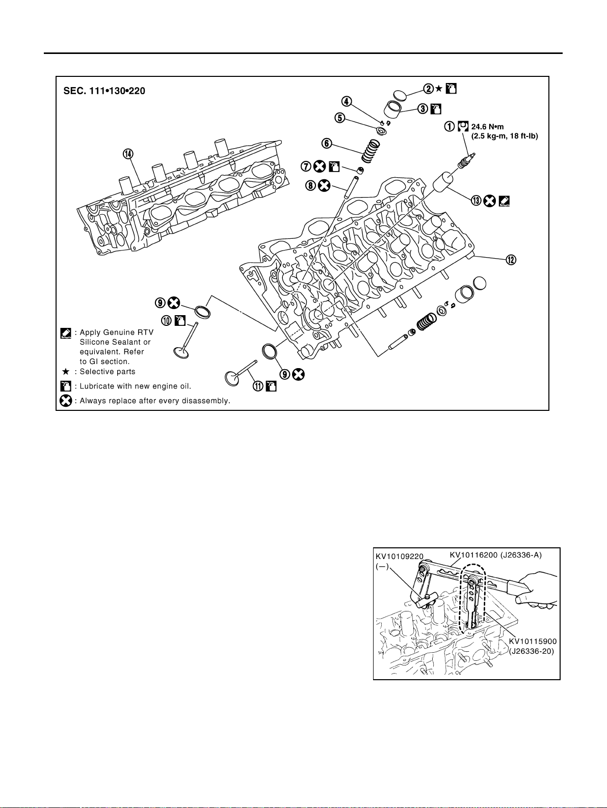
EM-228
[VK45DE]
CYLINDER HEAD
Revision: 2004 November 2004 FX35/FX45
Disassembly and Assembly ABS006IR
DISASSEMBLY
1. Remove spark plug with spark plug wrench (commercial service tool).
2. Remove adjusting shim and valve lifter.
● Identify installation positions, and store them without mixing them up.
3. Remove valve collet.
● Compress valve spring with valve spring compressor, attach-
ment and adapter (SST). Remove valve collet with magnetic
hand.
CAUTION:
When working, take care not to damage valve lifter holes.
4. Remove valve spring retainer and valve spring.
CAUTION:
Do not remove valve spring seat from valve spring.
5. Push valve stem to combustion chamber side, and remove valve.
● Identify installation positions, and store them without mixing them up.
1. Spark plug 2. Adjusting shim 3. Valve lifter
4. Valve collet 5. Valve spring retainer 6. Valve spring (with valve spring seat)
7. Valve oil seal 8. Valve guide 9. Valve seat
10. Valve (INT) 11. Valve (EXH) 12. Cylinder head (left bank)
13. Spark plug tube 14. Cylinder head (right bank)
PBIC2362E
PBIC2360E
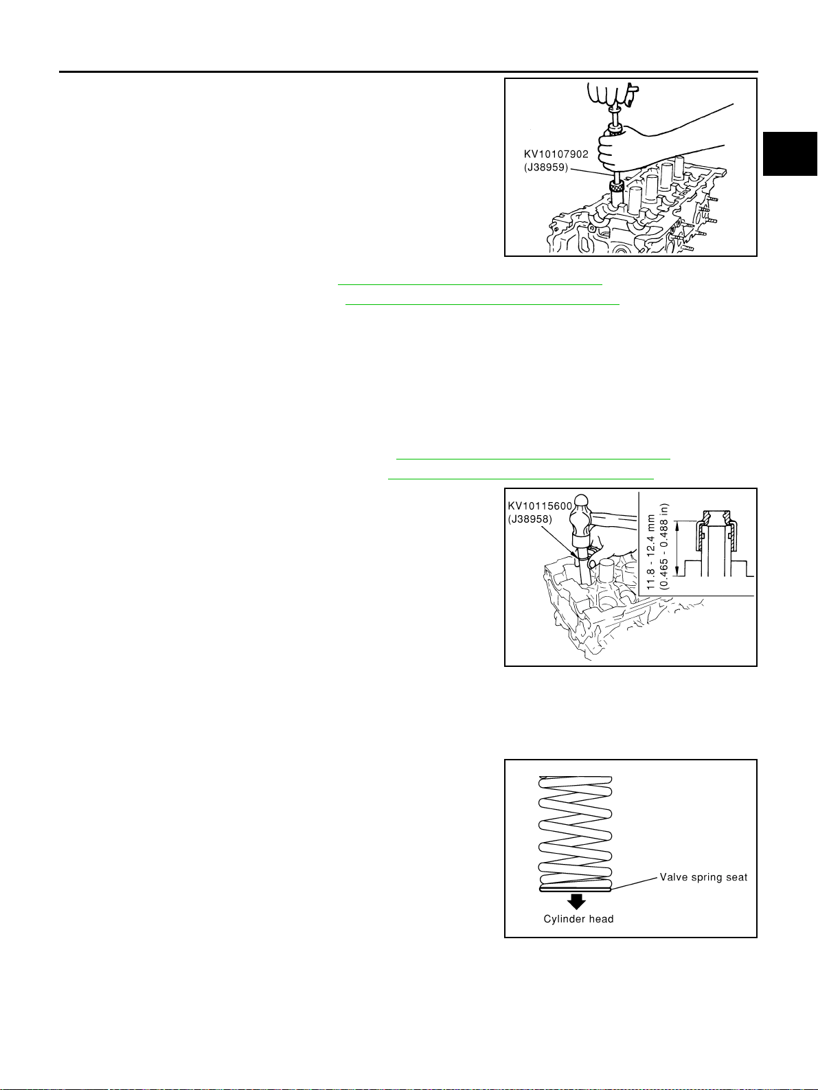
CYLINDER HEAD
EM-229
[VK45DE]
C
D
E
F
G
H
I
J
K
L
M
A
EM
Revision: 2004 November 2004 FX35/FX45
6. Remove valve oil seal with valve oil seal puller (SST).
7. If valve seat must be replaced, refer to EM-233, "
VALVE SEAT REPLACEMENT" .
8. If valve guide must be replaced, refer to EM-231, "
VALVE GUIDE REPLACEMENT" .
9. Remove spark plug tube, as necessary.
● Using pair of pliers, pull spark plug tube out of cylinder head.
CAUTION:
● Take care not to damage cylinder head.
● Once removed, spark plug tube will be deformed and cannot be reused. Do not remove it unless
absolutely necessary.
ASSEMBLY
1. When valve guide is removed, install it. Refer to EM-231, "VALVE GUIDE REPLACEMENT" .
2. When valve seat is removed, install it. Refer to EM-233, "
VALVE SEAT REPLACEMENT" .
3. Install valve oil seal.
● Install with valve oil seal drift (SST) to match dimension in the
figure.
4. Install valve.
● Install in the original position.
NOTE:
Larger diameter valves are for intake side.
5. Install valve spring.
● Install smaller pitch (valve spring seat side) to cylinder head
side.
6. Install valve spring retainer.
PBIC0072E
PBIC0073E
PBIC0074E
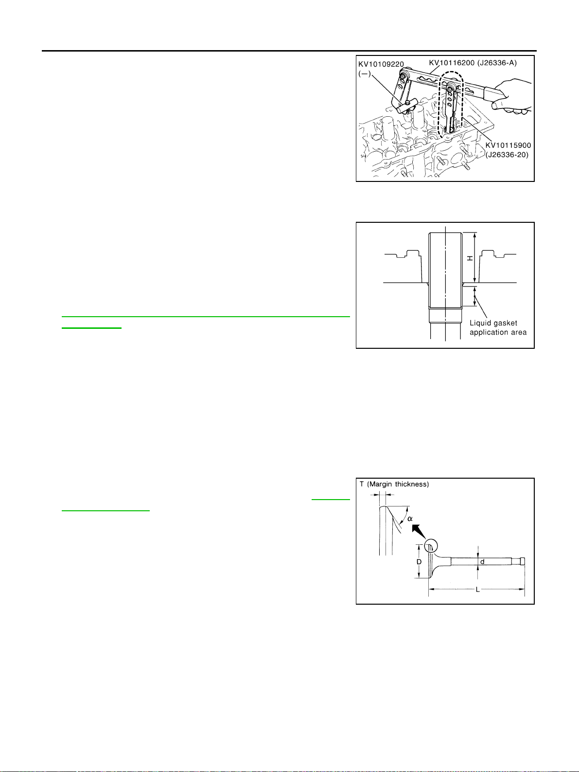
EM-230
[VK45DE]
CYLINDER HEAD
Revision: 2004 November 2004 FX35/FX45
7. Install valve collet.
● Compress valve spring with valve spring compressor, attach-
ment and adapter (SST). Install valve collet with magnetic
hand.
CAUTION:
When working, take care not to damage valve lifter holes.
● Tap stem edge lightly with plastic hammer after installation to
check its installed condition.
8. Install valve lifter and adjusting shim.
● Install in the original position.
9. Install spark plug tube.
● Press-fit spark plug tube following procedure below.
a. Remove old liquid gasket adhering to cylinder-head mounting
hole.
b. Apply liquid gasket to area within approximately 12 mm (0.47 in)
from edge of spark plug tube press-fit side.
Use Genuine RTV Silicone Sealant or equivalent . Refer to
GI-48, "
RECOMMENDED CHEMICAL PRODUCTS AND
SEALANTS" .
c. Using drift, press-fit spark plug tube so that its height “H” is as
specified in the figure.
CAUTION:
● When press-fitting, take care not to deform spark plug tube.
● After press-fitting, wipe off liquid gasket protruding onto cylinder-head upper face.
10. Install spark plug with spark plug wrench (commercial service tool).
Inspection After Disassembly ABS006IS
VALVE DIMENSIONS
● Check dimensions of each valve. For dimensions, refer to .
● If dimensions are out of the standard, replace valve.EM-270,
"Valve Dimensions" .
PBIC2360E
Standard press-fit height “H” :
: 38.4 - 39.4 mm (1.512 - 1.551 in)
KBIA1248E
SEM188A
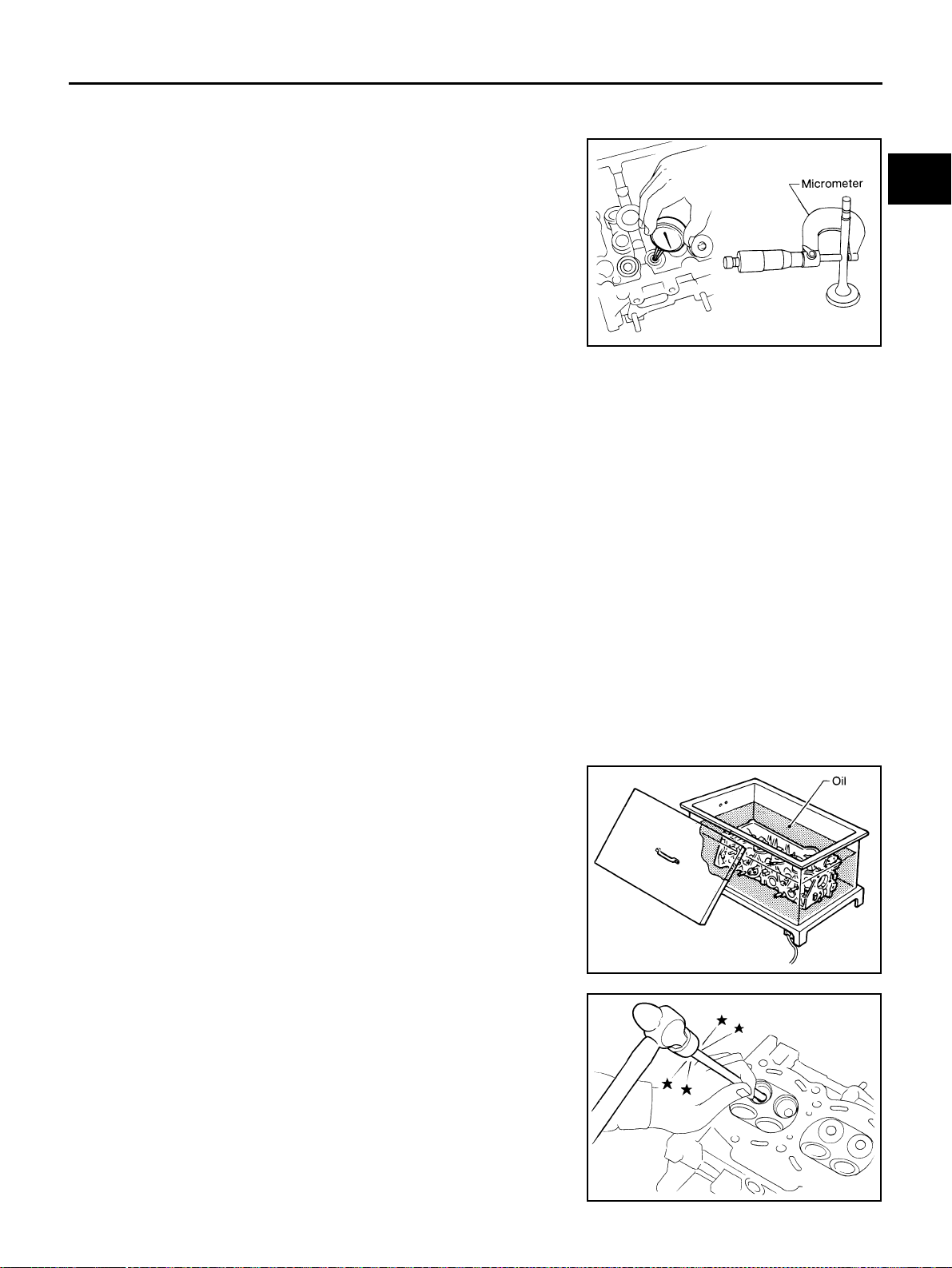
CYLINDER HEAD
EM-231
[VK45DE]
C
D
E
F
G
H
I
J
K
L
M
A
EM
Revision: 2004 November 2004 FX35/FX45
VALVE GUIDE CLEARANCE
Valve Stem Diameter
Measure diameter of valve stem with micrometer.
Valve Guide Inner Diameter
Measure inner diameter of valve guide with inside micrometer.
Valve Guide Clearance
(Valve guide clearance) = (Valve guide inner diameter) – (Valve stem diameter).
● If it exceeds the limit, replace valve and/or valve guide.
VALVE GUIDE REPLACEMENT
When valve guide is removed, replace with oversized [0.2 mm (0.008 in)] valve guide.
1. To remove valve guide, heat cylinder head to 110 to 130°C (230
to 266°F) by soaking in heated oil.
2. Drive out valve guide with a press [under a 20 kN (2 ton, 2.2 US
ton, 2.0 lmp ton) pressure] or hammer and suitable tool.
CAUTION:
Cylinder head contains heat. When working, wear protec-
tive equipment to avoid getting burned.
Standard
Intake : 5.972 - 5.980 mm (0.2351 - 0.2354 in)
Exhaust : 5.962 - 5.970 mm (0.2347 - 0.2350 in)
SEM938C
Standard
Intake and Exhaust : 6.000 - 6.018 mm (0.2362 - 0.2369 in)
Valve guide clearance:
Standard
Intake : 0.020 - 0.046 mm (0.0008 - 0.0018 in)
Exhaust : 0.030 - 0.056 mm (0.0012 - 0.0022 in)
Limit
Intake : 0.08 mm (0.003 in)
Exhaust : 0.1 mm (0.004 in)
SEM008A
SEM931C
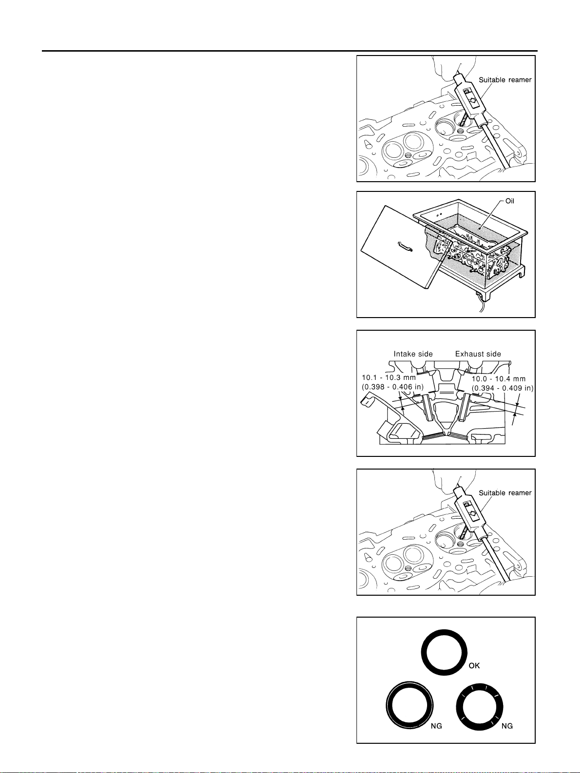
EM-232
[VK45DE]
CYLINDER HEAD
Revision: 2004 November 2004 FX35/FX45
3. Using valve guide reamer (commercial service tool), ream cylin-
der head valve guide hole.
4. Heat cylinder head to 110 to 130°C (230 to 266°F) by soaking in
heated oil.
5. Press valve guide from camshaft side to dimensions as in the
figure.
CAUTION:
Cylinder head contains heat. When working, wear protec-
tive equipment to avoid getting burned.
6. Using valve guide reamer (commercial service tool), apply
reamer finish to valve guide.
VALVE SEAT CONTACT
● After confirming that the dimensions of valve guides and valves
are within specifications, perform this procedure.
● Apply prussian blue (or white lead) onto contacting surface of
valve seat to check the condition of the valve contact on the sur-
face.
● Check if the contact area band is continuous all around the cir-
cumference.
● If not, grind to adjust valve fitting and check again. If the contact-
ing surface still has NG conditions even after the re-check,
replace valve seat.
Valve guide hole diameter (for service parts):
Intake and exhaust
: 10.175 - 10.196 mm (0.4006 - 0.4014 in)
SEM932C
SEM008A
PBIC0078E
Standard:
Intake and exhaust
: 6.000 - 6.018 mm (0.2362 - 0.2369 in)
SEM932C
SBIA0322E
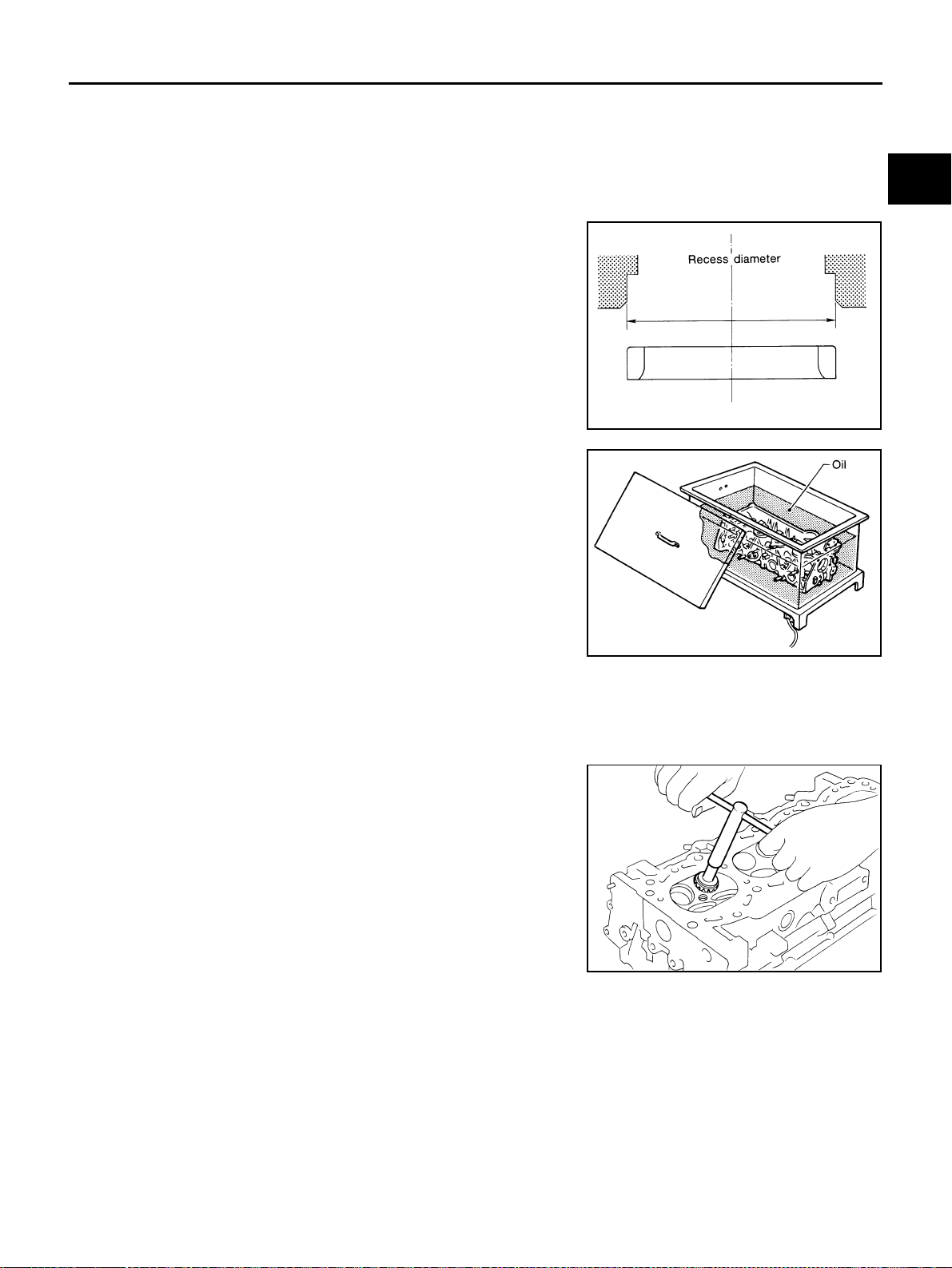
CYLINDER HEAD
EM-233
[VK45DE]
C
D
E
F
G
H
I
J
K
L
M
A
EM
Revision: 2004 November 2004 FX35/FX45
VALVE SEAT REPLACEMENT
When valve seat is removed, replace with oversized [0.5 mm (0.020 in)] valve seat.
1. Bore out old seat until it collapses. Boring should not continue beyond the bottom face of the seat recess
in cylinder head. Set the machine depth stop to ensure this.
CAUTION:
Prevent to scratch cylinder head by excessive boring.
2. Ream cylinder head recess diameter for service valve seat.
● Be sure to ream in circles concentric to valve guide center.
This will enable valve to fit correctly.
3. Heat cylinder head to 110 to 130°C (230 to 266°F) by soaking in
heated oil.
4. Provide valve seats cooled well with dry ice. Force fit valve seat into cylinder head.
CAUTION:
● Avoid directly touching cold valve seats.
● Cylinder head contains heat. When working, wear protective equipment to avoid getting burned.
5. Using valve seat cutter set (commercial service tool) or valve
seat grinder, finish seat to the specified dimensions.
CAUTION:
When using valve seat cutter, firmly grip cutter handle with
both hands. Then, press on the contacting surface all
around the circumference to cut in a single drive. Improper
pressure on with cutter or cutting many different times may
result in stage valve seat.
Oversize [0.5 mm (0.020 in)]
Intake : 37.500 - 37.516 mm (1.4764 - 1.4770 in)
Exhaust : 32.700 - 32.716 mm (1.2874 - 1.2880 in)
SEM795A
SEM008A
SEM934C
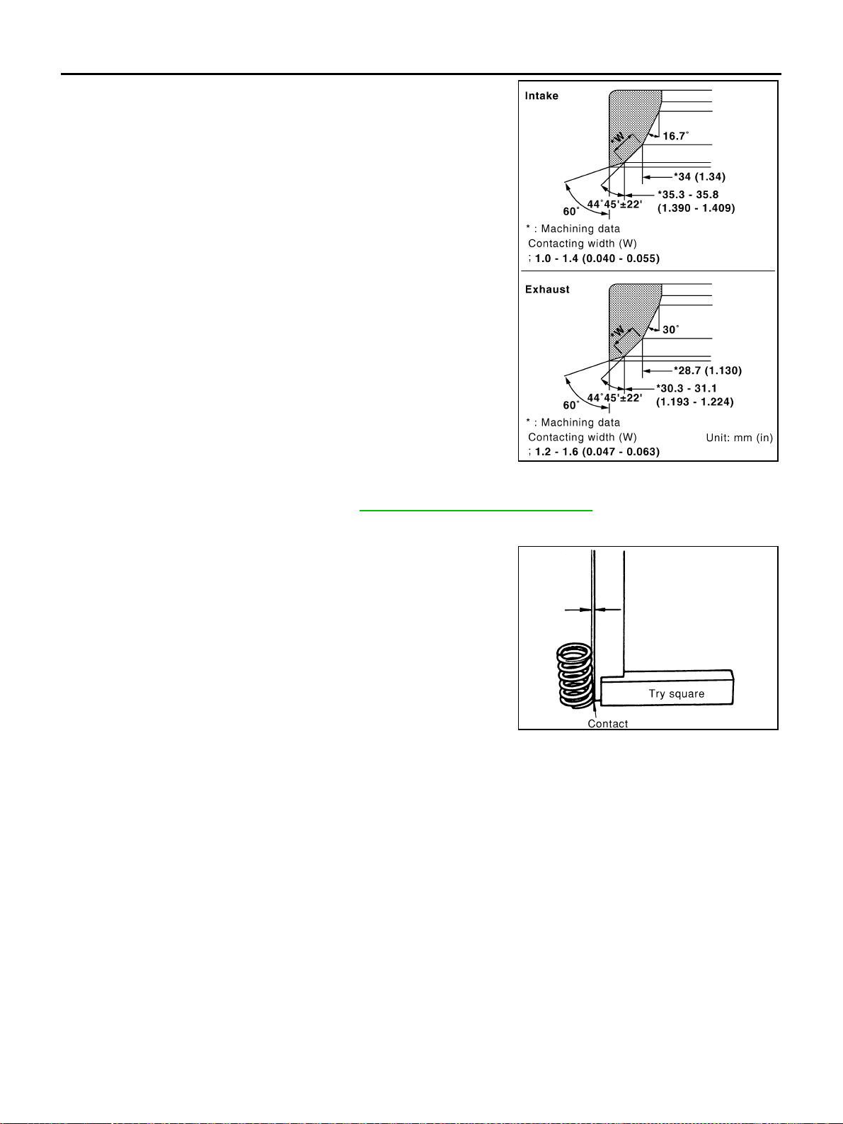
EM-234
[VK45DE]
CYLINDER HEAD
Revision: 2004 November 2004 FX35/FX45
Grind to obtain the dimensions indicated in the figure.
6. Using compound, grind to adjust valve fitting.
7. Check again for normal contact. Refer to EM-232, "
VALVE SEAT CONTACT" .
VALVE SPRING SQUARENESS
● Set try square along the side of valve spring and rotate spring.
Measure the maximum clearance between the top face of spring
and try square.
● If it exceeds the limit, replace valve spring.
PBIC2363E
Limit : 2.0 mm (0.079 in)
PBIC0080E

CYLINDER HEAD
EM-235
[VK45DE]
C
D
E
F
G
H
I
J
K
L
M
A
EM
Revision: 2004 November 2004 FX35/FX45
VALVE SPRING DIMENSIONS AND VALVE SPRING PRESSURE LOAD
● Check valve spring pressure at specified spring height.
● If the installation load or load with valve open is out of the standard, replace valve spring.
Standard:
Intake and exhaust
Free height
: 46.35 - 46.85 mm (1.8247 - 1.8444 in)
Installation height
: 33.8 mm (1.331 in)
Installation load
: 165 - 189 N (16.8 - 19.3 kg, 37 - 42 lb)
Height during valve open
: 24.4 mm (0.961 in)
Load with valve open
: 290 - 330 N (29.6 - 33.7 kg, 65 - 74 lb)
SEM113
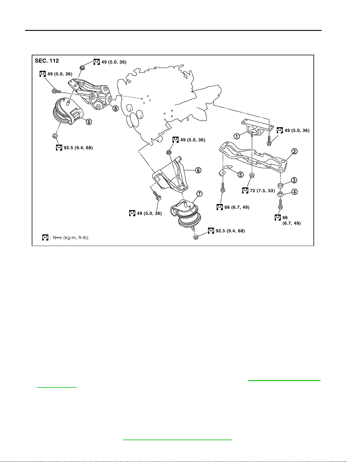
EM-236
[VK45DE]
ENGINE ASSEMBLY
Revision: 2004 November 2004 FX35/FX45
ENGINE ASSEMBLY PFP:10001
Removal and Installation ABS006IT
WARNING:
● Situate vehicle on a flat and solid surface.
● Place chocks at front and back of rear wheels.
● For engines not equipped with engine slingers, attach proper slingers and bolts described in
PARTS CATALOG.
CAUTION:
● Always be careful to work safely, avoid forceful or uninstructed operations.
● Do not start working until exhaust system and engine coolant are cool enough.
● If items or work required are not covered by the engine section, refer to the applicable sections.
● Always use the support point specified for lifting.
● Use either 2-point lift type or separate type lift as best you can. If board-on type is used for
unavoidable reasons, support at the rear axle jacking point with transmission jack or similar tool
before starting work, in preparation for the backward shift of center of gravity.
● For supporting points for lifting and jacking point at rear axle, refer to GI-42, "Garage Jack and
Safety Stand" .
REMOVAL
Outline
At first, remove engine, transmission assembly and front final drive with front suspension member downward.
Then separate engine from transmission.
Preparation
1. Release fuel pressure. Refer to EC-700, "FUEL PRESSURE RELEASE" .
1. Engine mounting insulator (rear) 2. Engine rear member 3. Grommet
4. Collar 5. Plate 6. Engine mounting bracket (LH)
7. Engine mounting insulator (LH) 8. Engine mounting bracket (RH) 9. Engine mounting insulator (RH)
PBIC2364E

ENGINE ASSEMBLY
EM-237
[VK45DE]
C
D
E
F
G
H
I
J
K
L
M
A
EM
Revision: 2004 November 2004 FX35/FX45
2. Drain engine coolant from radiator. Refer to CO-36, "Changing Engine Coolant" .
3. Disconnect both battery terminal. Refer to SC-4, "
BATTERY" .
4. Remove crankshaft position sensor (POS) from transmission.
CAUTION:
● Handle carefully to avoid dropping and shocks.
● Do not disassemble.
● Do not allow metal powder to adhere to magnetic part at sensor tip.
● Do not place sensors in a location where they are exposed to magnetism.
5. Remove the following parts:
● Hood assembly; Refer to BL-14, "HOOD" .
● Engine cover; Refer to EM-168, "ENGINE ROOM COVER" .
● Front and rear engine undercover
● Air duct (inlet), air duct and air cleaner case assembly; Refer to EM-172, "AIR CLEANER AND AIR
DUCT" .
● Drive belts; Refer to EM-169, "DRIVE BELTS" .
● Radiator and radiator hoses (upper and lower); Refer to CO-39, "RADIATOR" .
● Front road wheels and tires
6. Discharge refrigerant from A/C circuit. Refer to ATC-137, "
REFRIGERANT LINES" .
Engine Room LH
1. Disconnect engine room harness from the engine side and set it aside for easier work.
2. Disconnect heater hoses, and install plugs to avoid leakage of engine coolant.
3. Disconnect ground cable from exhaust manifold cover to vehicle.
4. Disconnect vacuum hose between vehicle and engine and set it aside.
5. Remove A/C piping from A/C compressor, and temporarily fasten it on vehicle with a rope. Refer to ATC-
139, "Components" .
Engine Room RH
1. Disconnect fuel feed hose and EVAP hose. Refer to EM-188, "FUEL INJECTOR AND FUEL TUBE" .
CAUTION:
Fit plugs onto disconnected hose to prevent fuel leak.
2. Disconnect engine room harness from the engine side and set it aside for easier work.
3. Disconnect ground cable from exhaust manifold cover to vehicle.
4. Disconnect vacuum hose between vehicle and engine and set it aside.
5. Disconnect reservoir tank of power steering oil pump from engine, and move it aside for easier work.
CAUTION:
When temporarily securing, keep reservoir tank upright to avoid a fluid leak.
Vehicle underbody
1. Remove front cross bar. Refer to FSU-6, "FRONT SUSPENSION ASSEMBLY" .
2. Disconnect power steering oil pump from engine. Move it from its location and secure with a rope for eas-
ier work. Refer to PS-33, "
Removal and Installation (VK45DE models)" .
3. Remove A/T fluid cooler tube. Refer to AT-269, "
Removal and Installation (AWD models)" .
4. Remove exhaust front tube and center muffler with power tool. Refer to EX-3, "
EXHAUST SYSTEM" .
5. Remove RH and LH transverse link mounting bolts and nuts. Refer to FSU-14, "
TRANSVERSE LINK" .
6. Disconnect stabilizer connecting rod lower. Refer to FSU-6, "
FRONT SUSPENSION ASSEMBLY" .
7. Remove A/T control rod at control device assembly side. Then temporarily secure it on transmission, so
that it does not sag. Refer to AT-233, "
SHIFT CONTROL SYSTEM" .
8. Remove rear plate cover, then remove drive plate to torque converter connecting bolts. Refer to AT-269,
"Removal and Installation (AWD models)" .
9. Disconnect steering lower joint at power steering gear assembly side, and release steering lower shaft.
Refer to PS-12, "
STEERING COLUMN" .
10. Remove rear propeller shaft. Refer to PR-6, "
REAR PROPELLER SHAFT" .
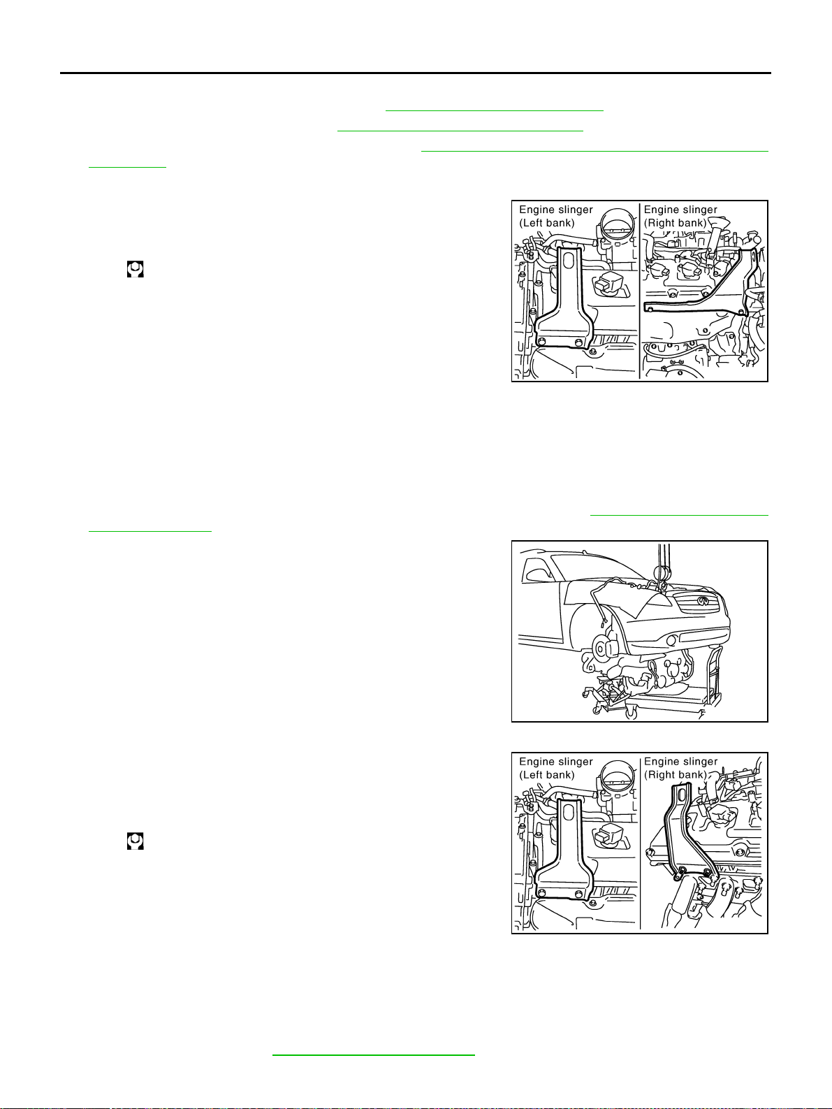
EM-238
[VK45DE]
ENGINE ASSEMBLY
Revision: 2004 November 2004 FX35/FX45
● After disconnection, plug the opening on transmission side.
11. Remove front drive shaft (both side). Refer to FAX-12, "
FRONT DRIVE SHAFT" .
12. Remove front propeller shaft. Refer to PR-4, "
FRONT PROPELLER SHAFT" .
13. Remove three way catalyst (both bank). Refer to EM-178, "
EXHAUST MANIFOLD AND THREE WAY
CATALYST" .
Removal Work
1. Install engine slingers into front of left bank cylinder head and
front of right bank cylinder head.
2. Lift with hoist and secure engine in position.
3. Use manual lift table caddy (commercial service tool) or equivalently rigid tool such as transmission jack.
Securely support bottom of suspension member and transmission.
CAUTION:
Put a piece of wood or something similar as the supporting surface, secure a completely stable
condition.
4. Remove front suspension member mounting nuts with power tool. Refer to FSU-6, "
FRONT SUSPEN-
SION ASSEMBLY" .
5. Carefully lower jack, or raise lift to remove engine, transmission
front final drive and front suspension member assembly. When
performing work, observe the following caution:
CAUTION:
● Confirm there is no interference with vehicle.
● Make sure that all connection points have been discon-
nected.
● Keep in mind the center of vehicle gravity changes. If
necessary, use jack(s) to support vehicle at rear jacking
point(s) to prevent it from falling it off the lift.
Separation Work
1. Change engine slinger installing to cylinder head (right bank).
NOTE:
In order to keep secure position when hoisting engine.
2. Remove engine mounting insulators (RH and LH) under side nut with power tool.
3. Lift with hoist and separate engine and transmission assembly from front suspension member.
CAUTION:
● Before and during this lifting, always check if any harnesses are left connected.
● Avoid damage to and oil/grease smearing or spills onto engine mounting insulator.
4. Remove alternator. Refer to SC-23, "
CHARGING SYSTEM" .
Slinger bolts:
:33.4 N·m (3.4 kg-m, 25 ft-lb)
PBIC1556E
PBIC1557E
Slinger bolts:
:33.4 N·m (3.4 kg-m, 25 ft-lb)
PBIC2447E
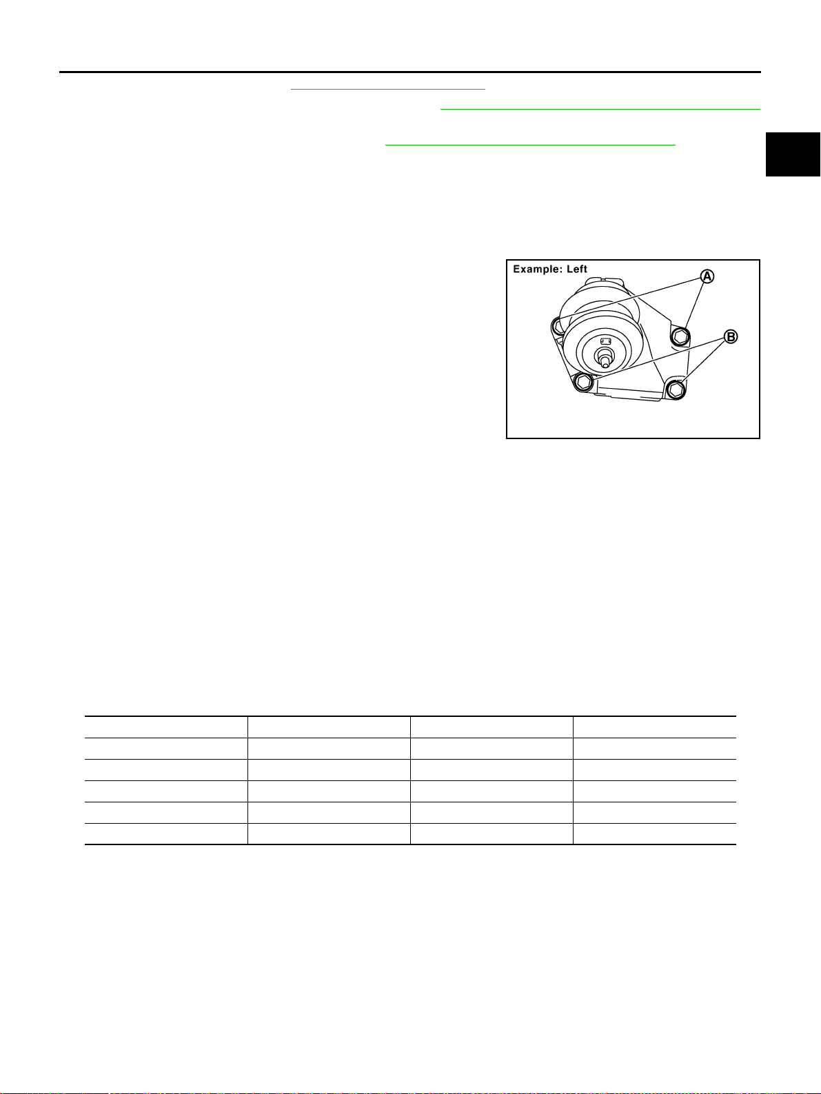
ENGINE ASSEMBLY
EM-239
[VK45DE]
C
D
E
F
G
H
I
J
K
L
M
A
EM
Revision: 2004 November 2004 FX35/FX45
5. Remove starter motor. Refer to SC-10, "STARTING SYSTEM" .
6. Separate engine from transmission assembly. Refer to AT-269, "
Removal and Installation (AWD models)"
.
7. Remove front final drive from engine. Refer to FFD-10, "
FRONT FINAL DRIVE ASSEMBLY" .
8. Remove engine mounting insulators (RH and LH) and brackets (RH and LH) from engine with power tool.
9. Remove engine rear member and engine mounting insulator (rear) from transmission.
INSTALLATION
Note to the following, and install in the reverse order of removal.
● Where positioning pin is used, be sure to securely insert it into the hole of mating part.
● When installing engine mount brackets (RH and LH) to cylinder
block, tighten two upper bolts (shown as “A” in the figure) first.
Then tighten two lower bolts (shown as “B” in the figure).
INSPECTION AFTER INSTALLATION
● Before starting engine, check the levels of engine coolant, engine oil and working fluid. If less than
required quantity, fill to the specified level.
● Use procedure below to check for fuel leakage.
– Turn ignition switch “ON” (with engine stopped). With fuel pressure applied to fuel piping, check for fuel
leakage at connection points.
– Start engine. With engine speed increased, check again for fuel leakage at connection points.
● Run engine to check for unusual noise and vibration.
● Warm up engine thoroughly to make sure there is no leakage of engine coolant, engine oil, working fluid,
fuel and exhaust gas.
● Bleed air from passages in pipes and tubes of applicable lines, such as in cooling system.
● After cooling down engine, again check amounts of engine coolant, engine oil and working fluid. Refill to
specified level, if necessary.
Summary of the inspection items:
PBIC2365E
Item Before starting engine Engine running After engine stopped
Engine coolant Level Leakage Level
Engine oil Level Leakage Level
Working fluid Level Leakage Level
Fuel — Leakage —
Exhaust gas — Leakage —
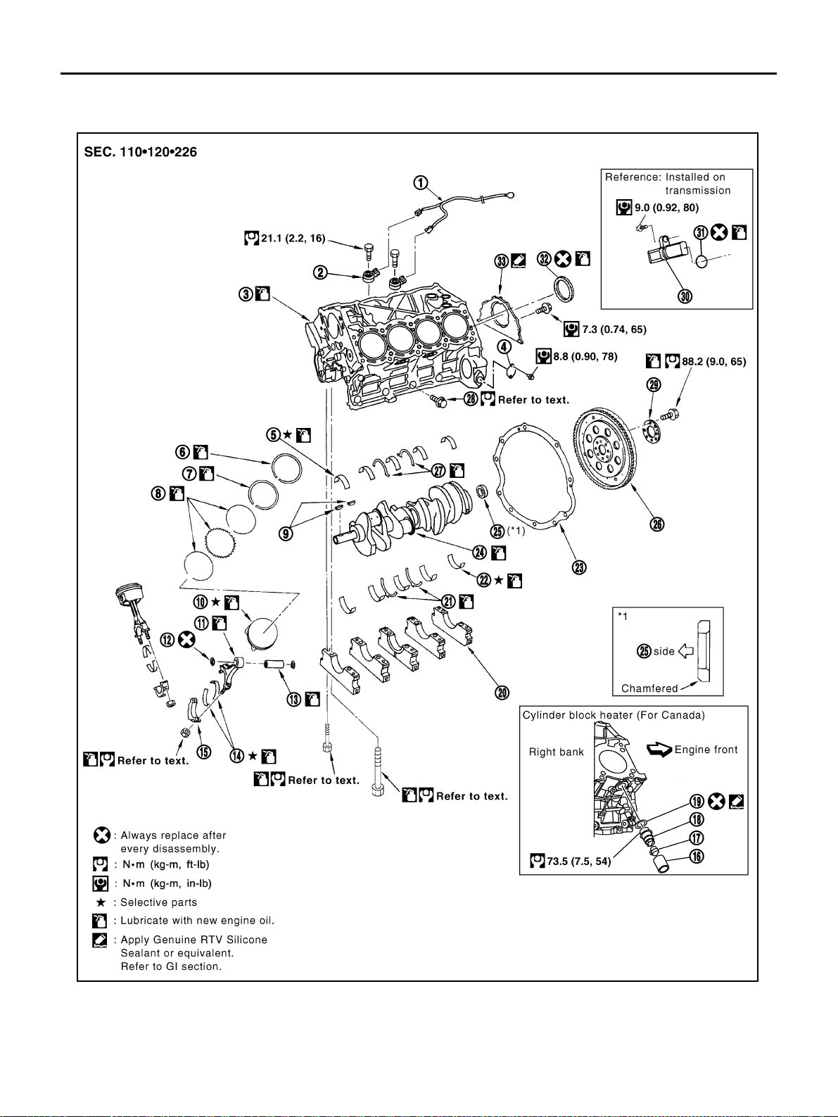
EM-240
[VK45DE]
CYLINDER BLOCK
Revision: 2004 November 2004 FX35/FX45
CYLINDER BLOCK PFP:11010
Disassembly and Assembly ABS006IU
1. Knock sensor sub harness 2. Knock sensor 3. Cylinder block
4. Cover 5. Main bearing 6. Top ring
7. Second ring 8. Oil ring 9. Crankshaft key
10. Piston 11. Connecting rod 12. Snap ring
PBIC2366E
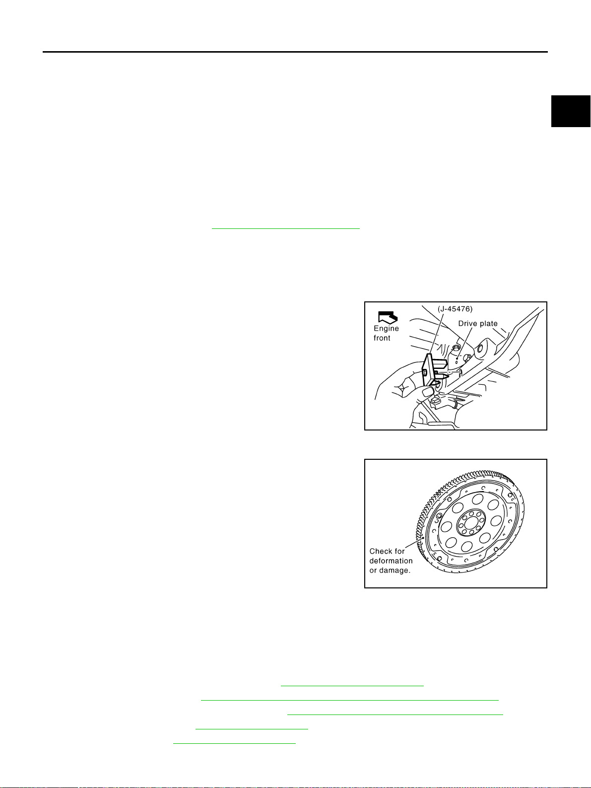
CYLINDER BLOCK
EM-241
[VK45DE]
C
D
E
F
G
H
I
J
K
L
M
A
EM
Revision: 2004 November 2004 FX35/FX45
DISASSEMBLY
NOTE:
Explained here is how to disassemble with engine stand supporting transmission surface. When using differ-
ent type of engine stand, note with difference in steps and etc.
1. Remove engine assembly from vehicle, and separate front suspension member, transmission and front
final drive from engine. Refer to EM-236, "
ENGINE ASSEMBLY" .
2. Remove the parts that may restrict installation of engine to widely use engine stand.
NOTE:
The procedure is described assuming that you use widely use engine holding the surface, to which trans-
mission is installed.
a. Remove drive plate.
● Holding ring gear with ring gear stopper (SST).
● Loosen mounting bolts diagonally order.
CAUTION:
● Do not disassemble drive plate.
● Do not place drive plate with signal plate facing down.
● When handling signal plate, take care not to damage or
scratch it.
● Handle signal plate in a manner that prevents it from
becoming magnetized.
b. Remove engine rear plate.
3. Lift engine with hoist to install it onto widely use engine stand.
CAUTION:
Use engine stand that has a load capacity [approximately 240kg (529 lb) or more] large enough for
supporting the engine weight.
● If the load capacity of stand is not adequate, remove the following parts beforehand to reduce the
potential risk of overturning stand.
– Intake manifolds (upper and lower); Refer to EM-174, "INTAKE MANIFOLD" .
– Exhaust manifold; Refer to EM-178, "EXHAUST MANIFOLD AND THREE WAY CATALYST" .
– Fuel tube and fuel injector assembly; Refer to EM-188, "FUEL INJECTOR AND FUEL TUBE" .
– A/C compressor; Refer to ATC-139, "Components" .
– Ignition coil; Refer to EM-185, "IGNITION COIL" .
13. Piston pin 14. Connecting rod bearing 15. Connecting rod bearing cap
16. Block heater protector 17. Connector cap 18. Cylinder block heater
19. Gasket 20. Main bearing cap 21. Thrust bearing
22. Main bearing 23. Rear plate 24. Crankshaft
25. Pilot convertor 26. Drive plate 27. Thrust bearing
28. Side bolt 29. Reinforcement plate 30. Crankshaft position sensor (POS)
31. O-ring 32. Rear oil seal 33. Rear oil seal retainer
PBIC1656E
PBIC2367E
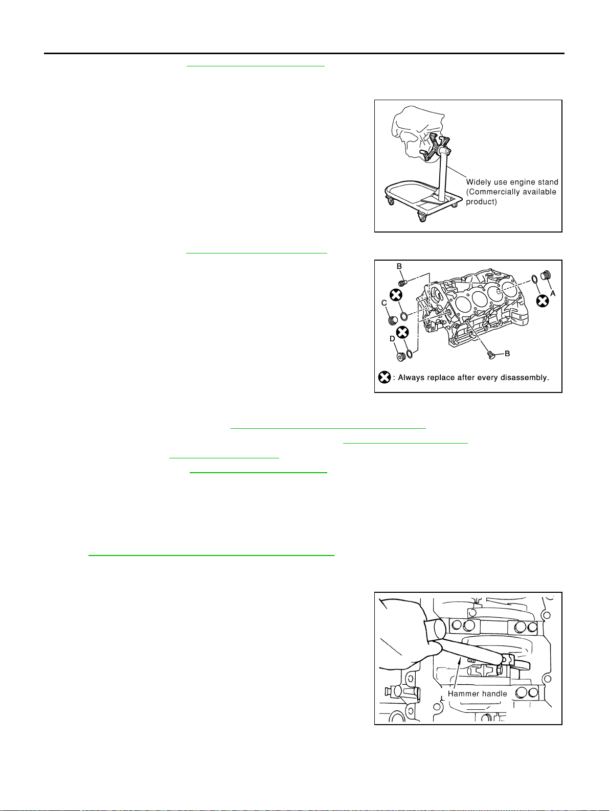
EM-242
[VK45DE]
CYLINDER BLOCK
Revision: 2004 November 2004 FX35/FX45
– Rocker cover; Refer to EM-193, "ROCKER COVER" .
– Other removable brackets
NOTE:
The figure shows an example of widely use engine stand that
can hold mating surface of transmission with drive plate and rear
plate removed.
CAUTION:
Before removing the hanging chains, make sure the engine
stand is stable and there is no risk of overturning.
4. Drain engine oil. Refer to LU-26, "
Changing Engine Oil" .
5. Drain engine coolant from inside engine by removing water
drain plugs “B” as shown in the figure.
6. Remove the following parts and related parts (The parts listed in step 3 are not included here.)
● Oil pan and oil strainer; Refer to EM-181, "OIL PAN AND OIL STRAINER" .
● Crankshaft pulley, front cover and timing chain; Refer to EM-196, "TIMING CHAIN" .
● Camshaft; Refer to EM-208, "CAMSHAFT" .
● Cylinder head; Refer to EM-224, "CYLINDER HEAD" .
7. Remove knock sensor.
CAUTION:
Carefully handle sensor, avoiding shocks.
8. Remove piston and connecting rod assembly as follows:
● Before removing piston and connecting rod assembly, check the connecting rod side clearance. Refer
to EM-256, "
CONNECTING ROD SIDE CLEARANCE" .
a. Position crankshaft pin corresponding to connecting rod to be removed onto the bottom dead center.
b. Remove connecting rod cap.
c. Using hammer handle or similar tool, push the piston and con-
necting rod assembly out to the cylinder head side.
9. Remove connecting rod bearings from connecting rod and connecting rod cap.
CAUTION:
Identify installation positions, and store them without mixing them up.
PBIC0085E
PBIC1265E
PBIC0086E
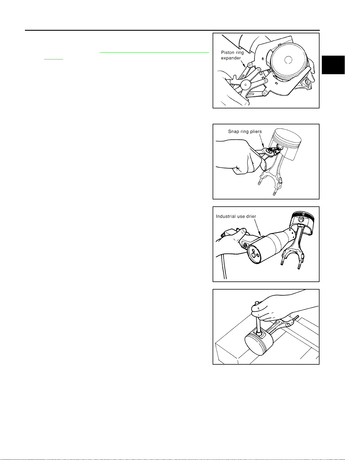
CYLINDER BLOCK
EM-243
[VK45DE]
C
D
E
F
G
H
I
J
K
L
M
A
EM
Revision: 2004 November 2004 FX35/FX45
10. Remove piston rings from piston.
● Before removing the piston rings, check the piston ring side
clearance. Refer to EM-257, "
PISTON RING SIDE CLEAR-
ANCE" .
● Use piston ring expander (commercial service tool).
CAUTION:
● When removing piston rings, be careful not to damage
piston.
● Be careful not to damage piston rings by expanding them
excessively.
11. Remove piston from connecting rod as follows:
a. Using snap ring pliers, remove the snap ring.
b. Heat piston to 60 to 70°C (140 to 158°F) with industrial use drier
or equivalent.
c. Push out piston pin with stick of outer diameter approximately 20
mm (0.8 in).
12. Remove rear oil seal retainer from cylinder block.
● Insert flat-blade screwdriver or similar tool between rear end of crankshaft counter weight and rear oil
seal retainer, and separate liquid gasket to remove.
CAUTION:
Be careful not to damage the mating surface.
13. Using flat-blade screwdriver or similar tool, and lever off rear oil seal from rear oil seal retainer.
14. Remove main bearing cap as follows:
PBIC0087E
PBIC0088E
PBIC0089E
EMM0072D
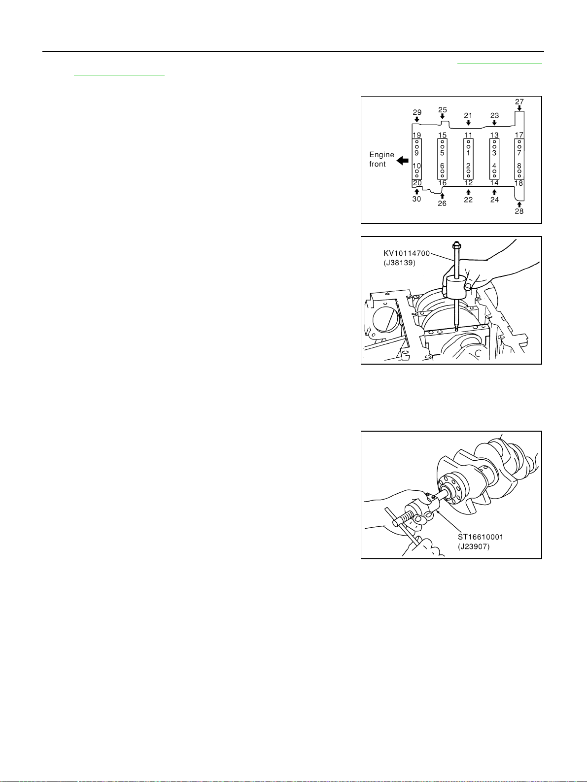
EM-244
[VK45DE]
CYLINDER BLOCK
Revision: 2004 November 2004 FX35/FX45
● Before loosening main bearing cap bolts, measure the crankshaft end play. Refer to EM-256, "CRANK-
SHAFT END PLAY" .
● Loosen bolts in several different steps.
a. Remove cover attached to the rear left side of cylinder block
(next to the starter motor housing).
NOTE:
Bolts (No. 27 shown in the figure) are installed on the inside of
cover.
b. Loosen side bolts (M10) starting from 30 to 21 to remove.
c. Loosen main bearing cap sub bolts (M9) starting from 20 to 11 to
remove.
d. Loosen main bearing cap bolts (M12) starting from 10 to 1 to
remove.
e. Using main bearing cap remover (SST), remove main bearing
cap.
15. Remove crankshaft.
16. Remove main bearings and thrust bearings from cylinder block and main bearing caps.
CAUTION:
Identify installation positions, and store them without mixing them up.
17. If the pilot converter must be removed, remove it from the rear
end of the crankshaft using pilot bushing puller (SST).
● It is possible to remove pilot converter without hoisting engine
with engine stand.
ASSEMBLY
1. Fully air-blow engine coolant and engine oil passages in cylinder block, cylinder bore and crankcase to
remove any foreign material.
CAUTION:
Use a goggles to protect your eye.
PBIC0090E
PBIC0091E
PBIC0092E
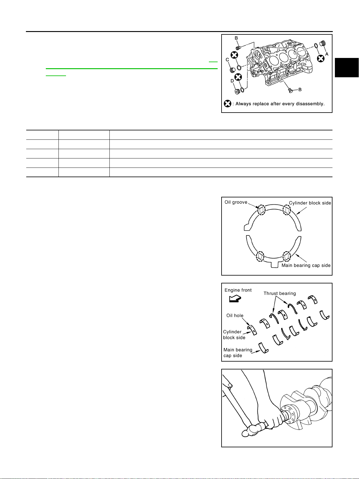
CYLINDER BLOCK
EM-245
[VK45DE]
C
D
E
F
G
H
I
J
K
L
M
A
EM
Revision: 2004 November 2004 FX35/FX45
2. Install each plug to the cylinder block. (Only screwed-type plugs
are shown in the figure.)
● Apply thread sealant to the thread of each plug.
Use Genuine Thread Sealant or equivalent. Refer to GI-
48, "RECOMMENDED CHEMICAL PRODUCTS AND SEAL-
ANTS".
● Replace copper washers with new ones.
● Tighten each plug as specified below.
3. Install main bearings and thrust bearings as follows:
a. Remove dust, dirt and oil on the bearing mating surfaces of cylinder block and main bearing caps.
b. Install thrust bearings to the both sides of the No. 3 journal hous-
ing on cylinder block and main bearing cap
● Install thrust bearings with the oil groove facing the crankshaft
arm (outside).
● Install thrust bearing with a protrusion on one end on cylinder
block, and thrust bearing with a protrusion at center on cap.
Align each protrusion with mating notch.
c. Install main bearings paying attention to the direction.
● Main bearing with oil hole and groove goes on cylinder block.
The one without them goes on main bearing cap.
● Before installing main bearings, apply engine oil to the bear-
ing surface (inside). Do not apply engine oil to the back sur-
face, but thoroughly clean it.
● When installing, align main bearing stopper protrusion to cut-
out of cylinder block and main bearing caps.
● Ensure the oil holes on cylinder block and those on the corre-
sponding bearing are aligned.
4. Install pilot converter to crankshaft.
● With drift [outer diameter: approx. 35 mm (1.38 in)], press-fit
as far as it will go.
PBIC1265E
Part Washer Tightening torque
A Yes 53.9 N·m (5.5 kg-m, 40 ft-lb)
B No 19.6 N·m (2.0 kg-m, 15 ft-lb)
C Yes 62.7 N·m (6.4 kg-m, 46 ft-lb)
D Yes 62.7 N·m (6.4 kg-m, 46 ft-lb)
PBIC2368E
PBIC2369E
EMP0569D
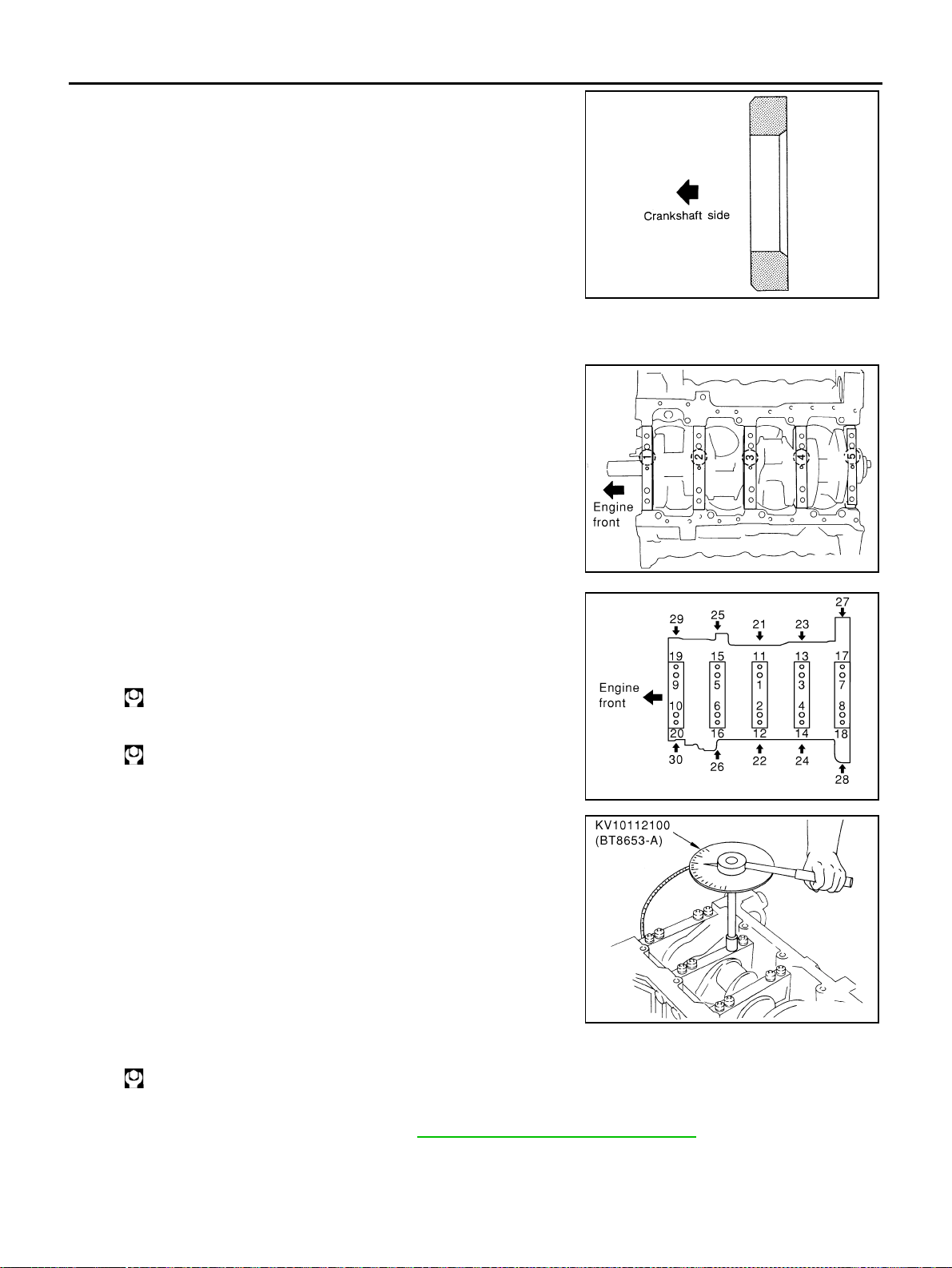
EM-246
[VK45DE]
CYLINDER BLOCK
Revision: 2004 November 2004 FX35/FX45
● Press-fit pilot converter with its chamfering side facing crank-
shaft as shown in the figure.
● It is possible to remove pilot converter without hoisting engine
with engine stand.
5. Install crankshaft to cylinder block.
● While turning crankshaft by hand, make sure it turns smoothly.
6. Install main bearing caps.
● Align the identification number to the journal position to install.
● Install the upper side of the identification number facing the
front of engine. (The number shall be read correctly from the
rear of engine.)
● Using plastic hammer or similar tool, tap them lightly to seat
them on the installation position.
NOTE:
Main bearing cap cannot be replaced as a single parts, because
it is machined together with cylinder block.
7. Install each main bearing cap bolt as follows:
a. Apply new engine oil to threads and seating surface of main
bearing cap bolts, and tighten all bolts temporarily.
b. Tighten main bearing cap bolt (M12) in order of 1 to 10.
c. Tighten main bearing cap sub bolt (M9) in order of 11 to 20.
d. Tighten main bearing cap bolt (M12) to 40 degrees clockwise in
order of 1 to 10. (Angle tightening)
CAUTION:
Use angle wrench (SST) to check tightening angle in step
“d” and “e”. Do not make judgment by visual inspection.
e. Tighten main bearing cap sub bolt (M9) to 30 degrees clockwise
in order of 11 to 20. (Angle tightening)
f. Tighten side bolt (M10) in order of 21 to 30.
● After installing main bearing cap bolts, make sure that crankshaft can be rotated smoothly.
● Check the crankshaft end play. Refer to EM-256, "CRANKSHAFT END PLAY" .
g. Install cover of cylinder block rear left side (next to the starter motor housing).
SEM537E
PBIC0095E
: 39.2 N·m (4.0 kg-m, 29 ft-lb)
: 29.4 N·m (3.0 kg-m, 22 ft-lb)
PBIC0090E
PBIC0096E
: 49 N·m (5.0 kg-m, 36 ft-lb)
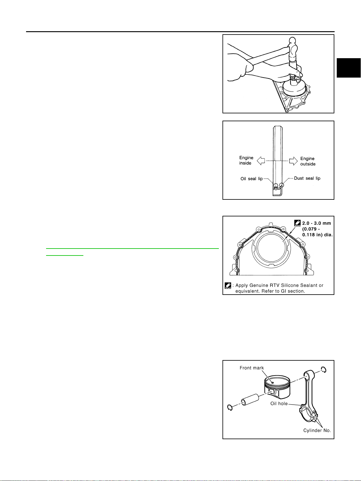
CYLINDER BLOCK
EM-247
[VK45DE]
C
D
E
F
G
H
I
J
K
L
M
A
EM
Revision: 2004 November 2004 FX35/FX45
8. Install rear oil seal to rear oil seal retainer with suitable drift.
● Tap until flattened with front edge of rear oil seal retainer. Do
not damage or scratch outer circumference of oil seal.
● Install new rear oil seal so that each seal lip is oriented as
shown in the figure.
9. Install rear oil seal retainer.
● Apply a continuous bead of liquid gasket with tube presser
[SST: WS39930000 ( — )] to rear oil seal retainer as
shown in the figure.
Use Genuine RTV Silicone Sealant or equivalent. Refer to
GI-48, "
RECOMMENDED CHEMICAL PRODUCTS AND
SEALANTS".
● Apply new engine oil to both oil seal lip and dust seal lip.
10. Install piston to connecting rod.
a. Using snap ring pliers, install new snap ring to the groove of the piston rear side.
● Insert it fully into groove to install.
b. Install piston to connecting rod.
● Using industrial use drier or similar tool, heat piston until piston pin can be pushed in by hand without
excess force [approx. 60 to 70°C (140 to 158°F)]. From the front to the rear, insert piston pin into piston
and connecting rod.
● Assemble so that the front mark on the piston head and the oil
holes and the cylinder No. on connecting rod are positioned
as shown in the figure.
c. Using snap ring pliers, install new snap rings to the groove of the
piston front side.
● Insert it fully into groove to install.
● After installing, make sure that connecting rod moves
smoothly.
Suitable drift
Outer diameter : 102 mm (4.02 in)
Inner diameter : 86 mm (3.39 in)
PBIC0097E
SEM715A
SBIA0391E
PBIC0099E
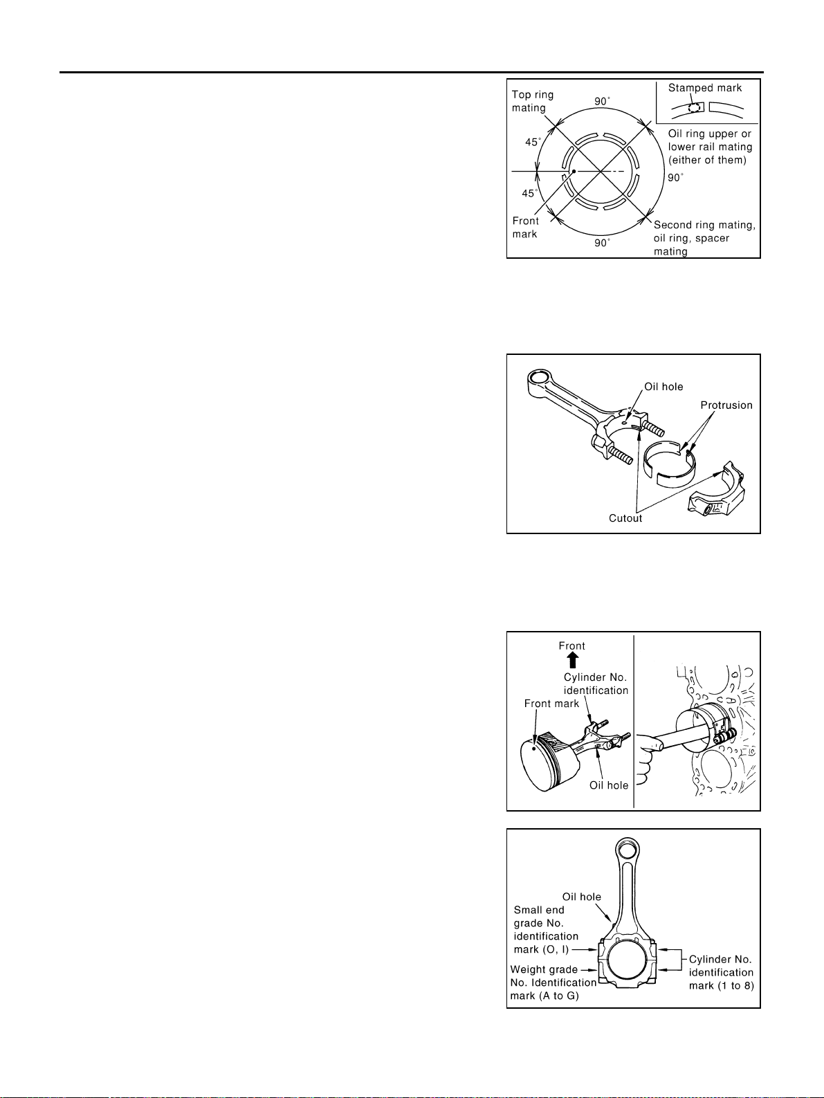
EM-248
[VK45DE]
CYLINDER BLOCK
Revision: 2004 November 2004 FX35/FX45
11. Using piston ring expander (commercial service tool), install pis-
ton rings.
CAUTION:
Be careful not to damage piston.
● Position each ring with the gap as shown in the figure, refer-
ring to the piston front mark.
● Install top ring and second ring with the stamped surface fac-
ing upward.
12. Install connecting rod bearings to connecting rod and connecting rod cap.
● Before installing connecting rod bearings, apply engine oil to the bearing surface (inside). Do not apply
engine oil to the back surface, but thoroughly clean it.
● When installing, align the connecting rod bearing stopper pro-
trusion with the cutout of connecting rod and connecting rod
cap to install.
● Ensure the oil holes on connecting rod and that on the corre-
sponding bearing are aligned.
13. Install piston and connecting rod assembly to crankshaft.
● Position the crankshaft pin corresponding to connecting rod to be installed onto the bottom dead center.
● Apply engine oil sufficiently to the cylinder bore, piston and crankshaft pin.
● Match the cylinder position with the cylinder No. on connecting rod to install.
● Be sure that front mark on piston head is facing front of
engine.
● Using piston ring compressor [SST: EM03470000 (J8037)],
install piston with the front mark on the piston head facing the
front of engine.
CAUTION:
Be careful not to damage cylinder wall and crankshaft pin,
resulting from an interference of the connecting rod big
end.
14. Install connecting rod cap.
● Match the stamped cylinder number marks on connecting rod
with those on cap to install.
Stamped mark
Top ring : R
Second ring : 2R
PBIC0100E
PBIC2370E
PBIC0102E
PBIC2164E
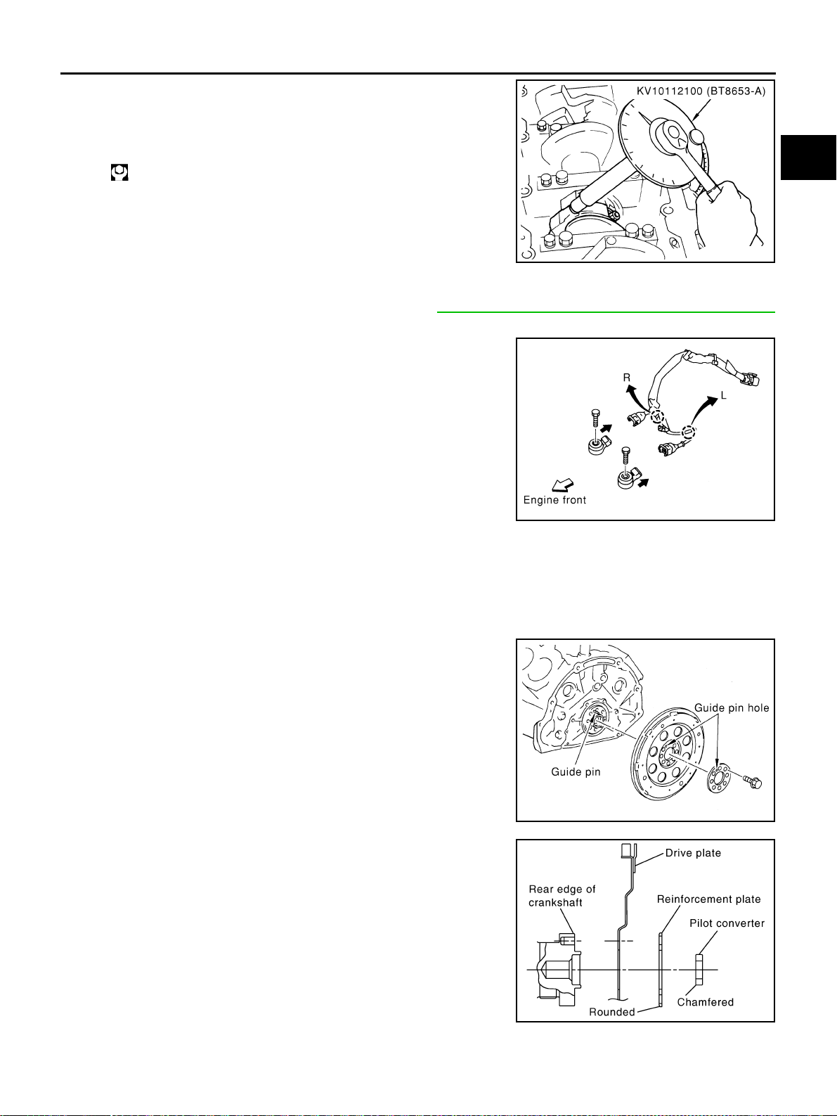
CYLINDER BLOCK
EM-249
[VK45DE]
C
D
E
F
G
H
I
J
K
L
M
A
EM
Revision: 2004 November 2004 FX35/FX45
15. Tighten the connecting rod nuts as follows:
a. Apply engine oil to the threads and seats of connecting rod bolts
and nuts.
b. Tighten nuts.
c. Then tighten all nuts 60 degrees clockwise. (Angle tightening)
CAUTION:
Use angle wrench (SST) to check tightening angle. Do not
make judgment by visual inspection.
● After tightening nuts, make sure that the crankshaft rotates
smoothly.
● Check the connecting rod side clearance. Refer to EM-256, "CONNECTING ROD SIDE CLEARANCE"
.
16. Install knock sensor.
● Install it with its connector facing the rear of engine.
● Install the sub-harness with its shorter branch line to the right
bank.
CAUTION:
● Do not tighten mounting bolts while holding connector.
● If any impact by dropping is applied to knock sensor,
replace it with new one.
NOTE:
● Make sure that there is no foreign material on the cylinder
block mating surface and the back surface of the knock sen-
sor.
● Make sure that the knock sensor does not interfere with other parts.
17. Install in the reverse order of removal after this step.
18. Remove engine assembly from engine stand.
19. Install drive plate.
● Align guide pin of crankshaft rear end with pin holes of each
parts to install.
● Install drive plate, reinforcement plate and pilot converter (if
not installed in step 4) as shown in the figure.
● Face chamfered or rounded edge side to crankshaft.
● Holding ring gear with ring gear stopper [SST: J-45476].
● Tighten mounting bolts crosswise over several times.
● When install pilot converter, using drift [outer diameter:
approx. 35 mm (1.38 in)]. Press-fit as far as it will go.
: 14.7 N·m (1.5 kg-m, 11 ft-lb)
PBIC0104E
PBIC0105E
PBIC0106E
PBIC1965E
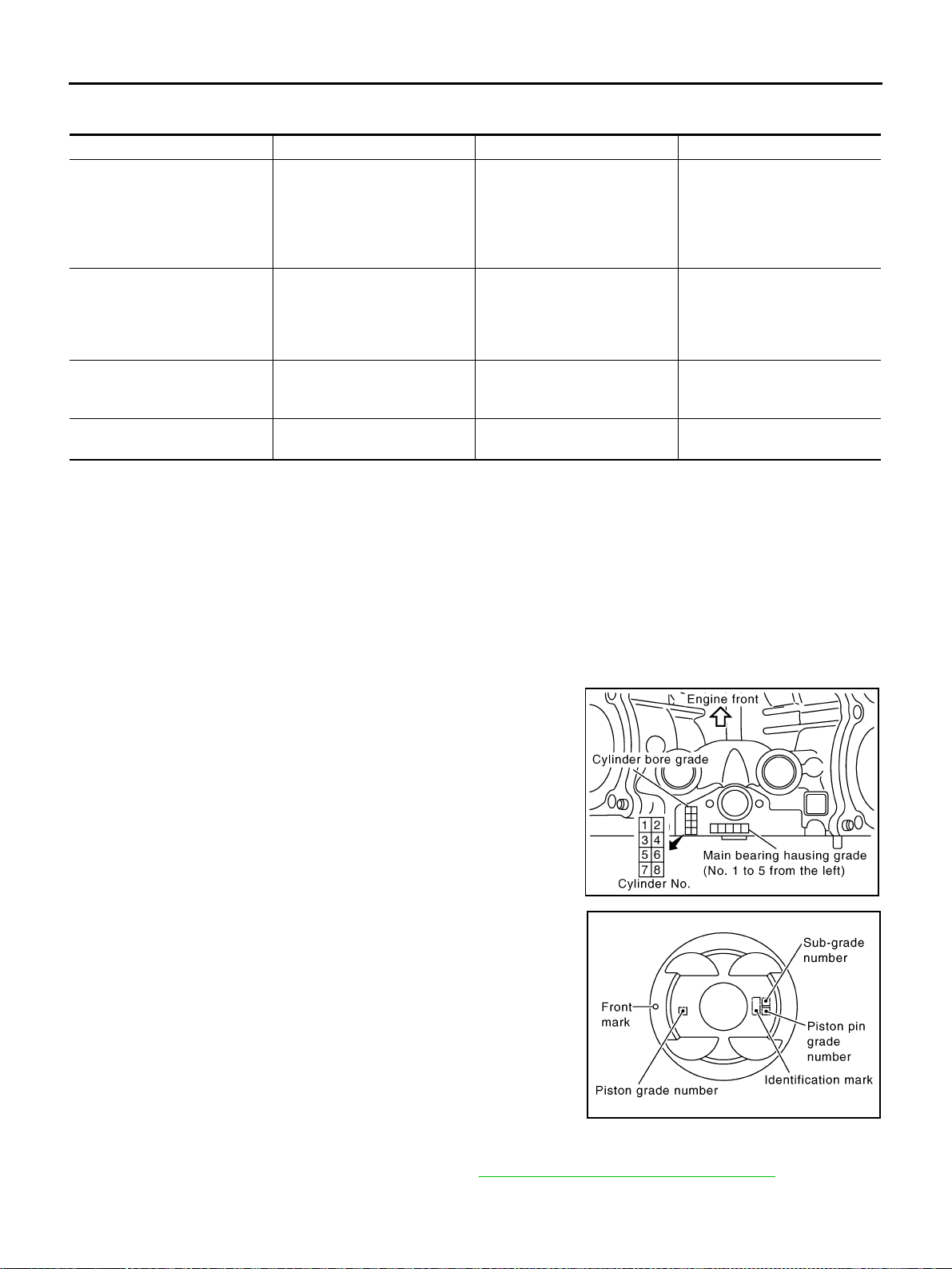
EM-250
[VK45DE]
CYLINDER BLOCK
Revision: 2004 November 2004 FX35/FX45
How to Select Piston and Bearing ABS006IV
DESCRIPTION
*: For the service parts, the grade for fitting cannot be selected between piston pin and connecting rod. (Only “0” grade is available.) The
information at the shipment from the plant is described as a reference.
● The identification grade stamped on each part is the grade for the dimension measured in new condition.
This grade cannot apply to reused parts.
● For reused or repaired parts, measure the dimension accurately. Determine the grade by comparing the
measurement with the values of each selection table.
● For details of the measurement method of each part, the reuse standards, and the selection method of the
selective fitting parts, refer to the text.
HOW TO SELECT PISTON
When New Cylinder Block Is Used:
Check the cylinder bore grade (“0”, “1” or “2”) on the rear upper side
between cylinder block banks, and select piston of the same grade.
NOTE:
Piston is available with piston pin as a set for the service part. (Only
“0” grade piston pin is available.)
When Cylinder Block Is Reused:
1. Measure the cylinder bore inner diameter. Refer to EM-260, "Cylinder Bore Inner Diameter" .
2. Determine the bore grade by comparing the measurement with the values the “Cylinder bore inner diame-
ter” of the “Piston Selection Table”. Select piston of the same grade.
Selection points Selection parts Selection items Selection methods
Between cylinder block to
crankshaft
Main bearing
Main bearing grade
(bearing thickness)
Determined by match of cylin-
der block bearing housing
grade (inner diameter of hous-
ing) and crankshaft journal
grade (outer diameter of jour-
nal)
Between crankshaft to connect-
ing rod
Connecting rod bearing
Connecting rod bearing grade
(bearing thickness)
Combining service grades for
connecting rod big end diame-
ter and crankshaft pin outer
diameter determine connecting
rod bearing selection.
Between cylinder block to pis-
ton
Piston and piston pin assembly
(Piston is available together
with piston pin as assembly.)
Piston grade
(piston skirt diameter)
Piston grade = cylinder bore
grade (inner diameter of bore)
Between piston to connecting
rod*
———
PBIC2371E
PBIC2372E
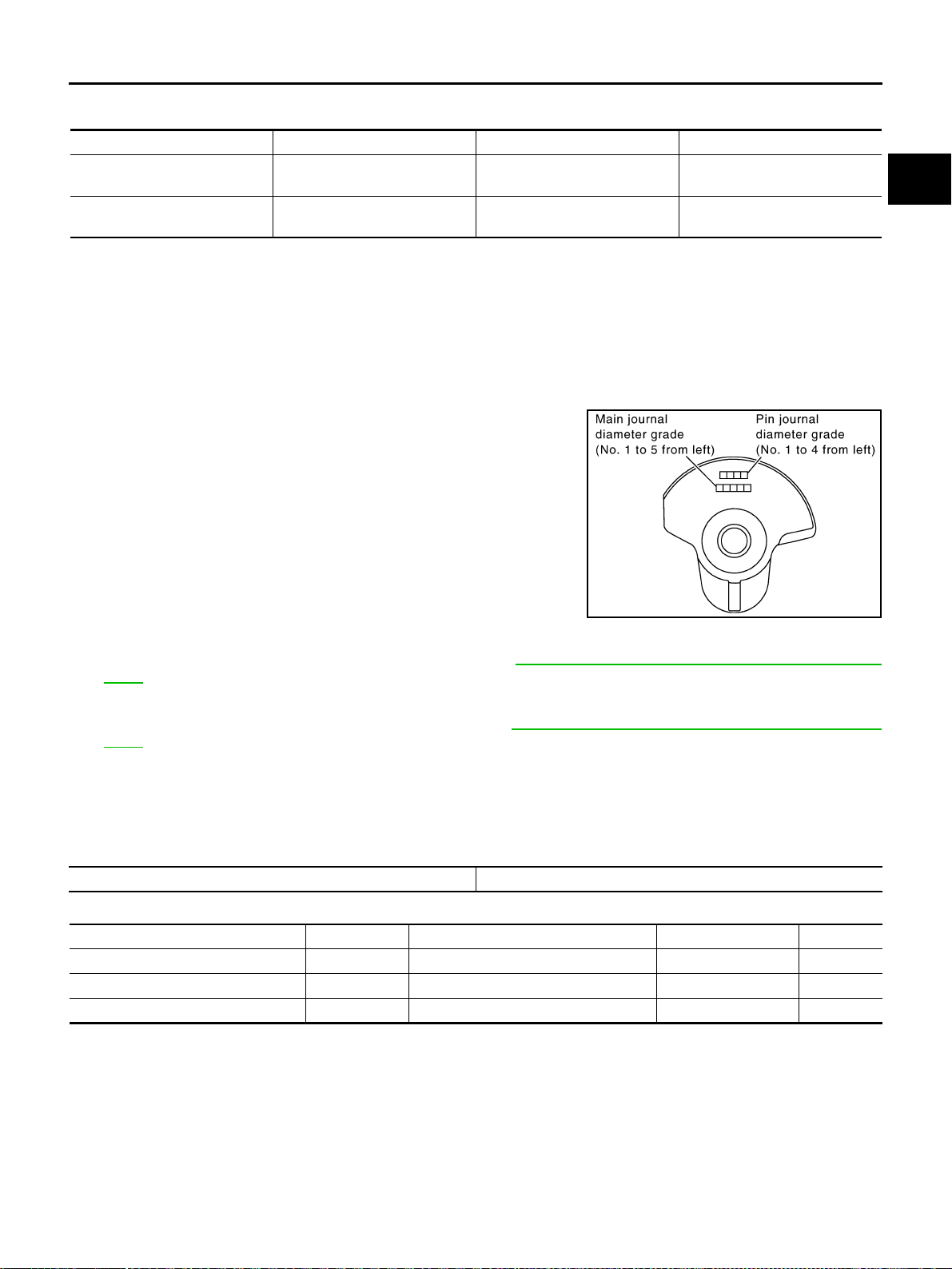
CYLINDER BLOCK
EM-251
[VK45DE]
C
D
E
F
G
H
I
J
K
L
M
A
EM
Revision: 2004 November 2004 FX35/FX45
Piston Selection Table
Unit: mm (in)
NOTE:
● Piston is available together with piston pin as assembly.
● Piston pin (piston pin hole) grade is provided only for the parts installed at the plant. For service parts, no
piston pin grades can be selected. (Only “0” grade is available.)
● No second grade mark is available on piston.
HOW TO SELECT CONNECTING ROD BEARING
When New Connecting Rod and Crankshaft Are Used:
Check pin diameter grade (“0”, “1” or “2”) on front of crankshaft, and
select connecting rod bearing of the same grade.
NOTE:
There is no grading for connecting rod big end diameter.
When Crankshaft and Connecting Rod Are Reused:
1. Measure the connecting rod big end diameter. Refer to EM-258, "CONNECTING ROD BIG END DIAME-
TER" .
2. Make sure that the connecting rod big end diameter is within the standard value.
3. Measure the crankshaft pin journal diameter. Refer to EM-262, "
CRANKSHAFT PIN JOURNAL DIAME-
TER" .
4. Determine the grade of crankshaft pin diameter grade by corresponding to the measured dimension in
“Crankshaft pin journal diameter” column of “Connecting Rod Bearing Selection Table”.
5. Select connecting rod bearing of the same grade.
Connecting Rod Bearing Selection Table
Unit: mm (in)
Unit: mm (in)
Under Size Bearings Usage Guide
● When the specified connecting rod bearing oil clearance is not obtained with standard size connecting rod
bearings, use undersize (US) bearings.
● When using undersize bearing, measure the connecting rod bearing inner diameter with bearing installed,
and grind crankshaft pin so that the connecting rod bearing oil clearance satisfies the standard.
Grade 1 2 (or no mark) 3
Cylinder bore inner diameter
93.000 / 93.010
(3.6614 / 3.6618)
93.010 / 93.020
(3.6618 / 3.6622)
93.020 / 93.030
(3.6622 / 3.6626)
Piston skirt diameter
92.980 / 92.990
(3.6606 / 3.6610)
92.990 / 93.000
(3.6610 / 3.6614)
93.000 / 93.010
(3.6614 / 3.6618)
PBIC2374E
Connecting rod big end diameter 55.000 - 55.013 (2.1654 - 2.1659)
Crankshaft pin journal diameter Grade (Mark) Dimension (Bearing thickness range) Bearing grade No. Color
51.968 - 51.974 (2.0460 - 2.0462) 0 1.500 - 1.503 (0.0591 - 0.0592) STD 0 No color
51.962 - 51.968 (2.0457 - 2.0460) 1 1.503 - 1.506 (0.0592 - 0.0593) STD 1 Brown
51.956 - 51.962 (2.0455 - 2.0457) 2 1.506 - 1.509 (0.0593 - 0.0594) STD 2 Green
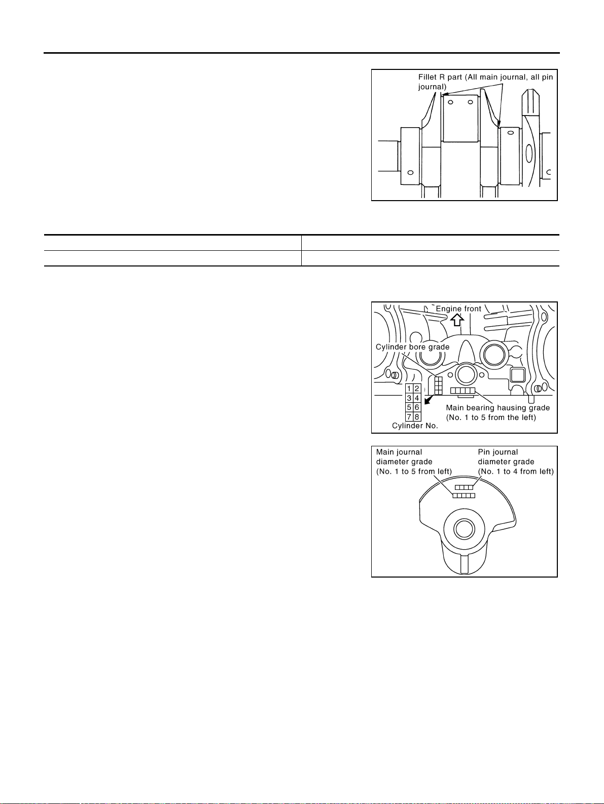
EM-252
[VK45DE]
CYLINDER BLOCK
Revision: 2004 November 2004 FX35/FX45
CAUTION:
In grinding crankshaft pin to use undersize bearings, keep
the fillet R [1.5 mm (0.059 in)].
Bearing undersize table
Unit: mm (in)
HOW TO SELECT MAIN BEARING
When New Cylinder Block and Crankshaft Are Used:
1. “Main Bearing Selection Table” rows correspond to main bearing
housing grade on rear upper side between cylinder block banks.
2. “Main Bearing Selection Table” columns correspond to main
journal diameter grade on front side of crankshaft.
3. Select main bearing grade at the point where selected row and column meat in “Main Bearing Selection
Table”.
CAUTION:
● Initial clearance for No. 1, 5 journal and No. 2, 3, 4 journal is different. Use two different selection
table for each part.
● No. 1, 5 journal and No. 2, 3, 4 journal have the same signs but different measures. Do not con-
fuse.
4. Apply sign at crossing in above step 3 to “Main Bearing Grade Table”.
NOTE:
● “Main Bearing Grade Table” applies to all journals.
● Service parts is available as a set of both upper and lower.
PBIC2373E
Size Thickness
US 0.25 (0.0098) 1.626 - 1.634 (0.0640 - 0.0643)
PBIC2371E
PBIC2374E
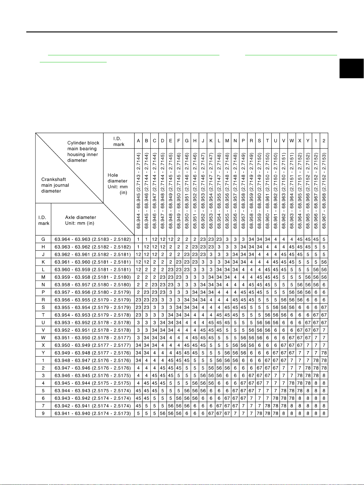
CYLINDER BLOCK
EM-253
[VK45DE]
C
D
E
F
G
H
I
J
K
L
M
A
EM
Revision: 2004 November 2004 FX35/FX45
When Cylinder Block and Crankshaft Are Reused:
1. Measure cylinder block main bearing housing inner diameter and crankshaft main journal diameter. Refer
to EM-260, "
MAIN BEARING HOUSING INNER DIAMETER" and EM-261, "CRANKSHAFT MAIN
JOURNAL DIAMETER" .
2. Correspond the measured dimension in “Cylinder block main bearing housing inner diameter” row of
“Main Bearing Selection Table”.
3. Correspond the measured dimension in “Crankshaft main journal diameter” column of “Main Bearing
Selection Table”.
4. Follow step 3 and later in “When New Cylinder Block and Crankshaft are Used:”.
Main Bearing Selection Table (No. 1 and 5 Journal)
PBIC2375E
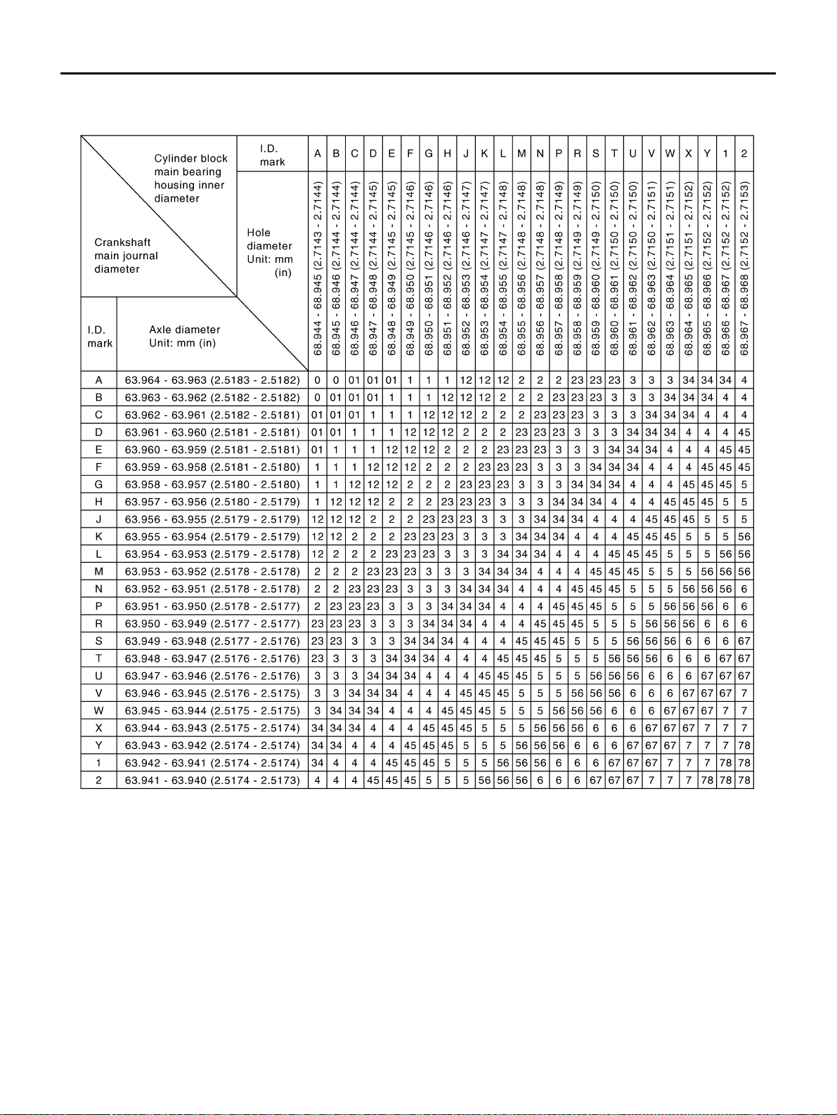
EM-254
[VK45DE]
CYLINDER BLOCK
Revision: 2004 November 2004 FX35/FX45
Main Bearing Selection Table (No. 2, 3 and 4 Journal)
PBIC2376E

CYLINDER BLOCK
EM-255
[VK45DE]
C
D
E
F
G
H
I
J
K
L
M
A
EM
Revision: 2004 November 2004 FX35/FX45
Main Bearing Grade Table (All Journals)
Unit: mm (in)
Use Undersize Bearing Usage Guide
● When the specified main bearing oil clearance is not obtained with standard size main bearings, use
underside (US) bearing.
● When using undersize (US) bearing, measure the main bearing inner diameter with bearing installed, and
grind main journal so that the main bearing oil clearance satisfies the standard.
CAUTION:
In grinding crankshaft main journal to use undersize bear-
ings, keep the fillet R [1.5 mm (0.059 in)].
Bearing undersize table
Unit: mm (in)
Grade number Thickness Identification color Remarks
0 2.483 - 2.486 (0.0978 - 0.0979) Black
Grade and color are the same
for upper and lower bearings.
1 2.486 - 2.489 (0.0979 - 0.0980) Brown
2 2.489 - 2.492 (0.0980 - 0.0981) Green
3 2.492 - 2.495 (0.0981 - 0.0982) Yellow
4 2.495 - 2.498 (0.0982 - 0.0983) Blue
5 2.498 - 2.501 (0.0983 - 0.0985) Pink
6 2.501 - 2.504 (0.0985 - 0.0986) Purple
7 2.504 - 2.507 (0.0986 - 0.0987) White
8 2.507 - 2.510 (0.0987 - 0.0988) Red
01
UPR 2.483 - 2.486 (0.0978 - 0.0979) Black
Grade and color are different
for upper and lower bearings.
LWR 2.486 - 2.489 (0.0979 - 0.0980) Brown
12
UPR 2.486 - 2.489 (0.0979 - 0.0980) Brown
LWR 2.489 - 2.492 (0.0980 - 0.0981) Green
23
UPR 2.489 - 2.492 (0.0980 - 0.0981) Green
LWR 2.492 - 2.495 (0.0981 - 0.0982) Yellow
34
UPR 2.492 - 2.495 (0.0981 - 0.0982) Yellow
LWR 2.495 - 2.498 (0.0982 - 0.0983) Blue
45
UPR 2.495 - 2.498 (0.0982 - 0.0983) Blue
LWR 2.498 - 2.501 (0.0983 - 0.0985) Pink
56
UPR 2.498 - 2.501 (0.0983 - 0.0985) Pink
LWR 2.501 - 2.504 (0.0985 - 0.0986) Purple
67
UPR 2.501 - 2.504 (0.0985 - 0.0986) Purple
LWR 2.504 - 2.507 (0.0986 - 0.0987) White
78
UPR 2.504 - 2.507 (0.0986 - 0.0987) White
LWR 2.507 - 2.510 (0.0987 - 0.0988) Red
PBIC2373E
Size Thickness
US 0.25 (0.0098) 2.618 - 2.626 (0.1031 - 0.1034)
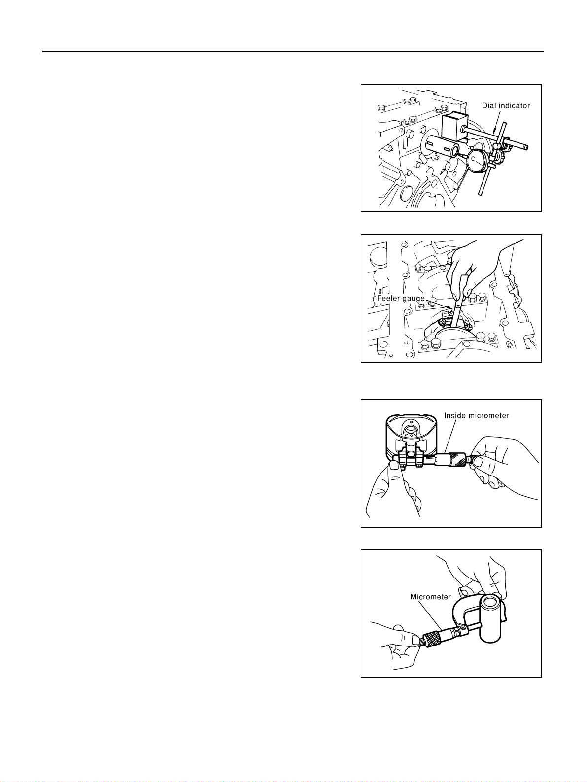
EM-256
[VK45DE]
CYLINDER BLOCK
Revision: 2004 November 2004 FX35/FX45
Inspection After Disassembly ABS006IW
CRANKSHAFT END PLAY
● Measure the clearance between thrust bearings and crankshaft
arm when crankshaft is moved fully forward or backward with
dial indicator.
● If the measured value exceeds the limit, replace thrust bearings,
and measure again. If it still exceeds the limit, replace crank-
shaft also.
CONNECTING ROD SIDE CLEARANCE
● Measure side clearance between connecting rod and crankshaft
arm with feeler gauge.
● If the measured value exceeds the limit, replace connecting rod,
and measure again. If it still exceeds the limit, replace crank-
shaft also.
PISTON TO PISTON PIN OIL CLEARANCE
Piston Pin Hole Diameter
Measure the inner diameter of piston pin hole with inside microme-
ter.
Piston Pin Outer Diameter
Measure the outer diameter of piston pin with micrometer.
Piston to Piston Pin Oil Clearance
(Piston to piston pin oil clearance) = (Piston pin hole diameter) – (Piston pin outer diameter)
● If clearance is out of the standard, replace piston and piston pin assembly.
Standard : 0.10 - 0.25 mm (0.0039 - 0.0098 in)
Limit : 0.30 mm (0.0118 in)
PBIC2377E
Standard : 0.20 - 0.35 mm (0.0079 - 0.0138 in)
Limit : 0.40 mm (0.0157 in)
PBIC0115E
Standard : 21.993 - 22.005 mm (0.8659 - 0.8663 in)
PBIC0116E
Standard : 21.989 - 22.001 mm (0.8657 - 0.8662 in)
PBIC0117E
Standard : 0.002 - 0.006 mm (0.0001 - 0.0002 in)
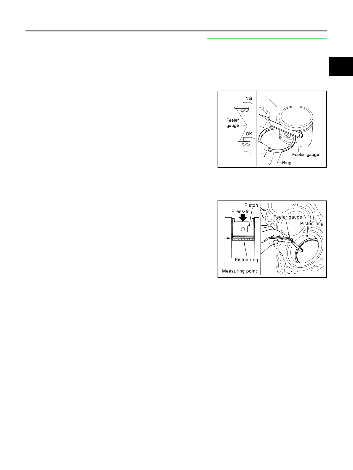
CYLINDER BLOCK
EM-257
[VK45DE]
C
D
E
F
G
H
I
J
K
L
M
A
EM
Revision: 2004 November 2004 FX35/FX45
● When replacing piston and piston pin assembly, refer to EM-260, "PISTON TO CYLINDER BORE
CLEARANCE" .
NOTE:
● Piston is available together with piston pin as assembly.
● Piston pin (piston pin hole) grade is provided only for the parts installed at the plant. For service parts,
no piston pin grades can be selected. (Only “0” grade is available.)
PISTON RING SIDE CLEARANCE
● Measure side clearance of piston ring and piston ring groove
with feeler gauge.
● If the measured value exceeds the limit, replace piston ring, and measure again. If it still exceeds the limit,
replace piston also.
PISTON RING END GAP
● Make sure that cylinder bore inner diameter is within specifica-
tion. Refer to EM-260, "
Cylinder Bore Inner Diameter" .
● Lubricate with new engine oil to piston and piston ring, and then
insert piston ring until middle of cylinder with piston, and mea-
sure piston ring end gap with feeler gauge.
● If the measured value exceeds the limit, replace piston ring, and measure again. If it still exceeds the limit,
re-bore cylinder and use oversize piston and piston rings.
Standard:
Top ring : 0.045 - 0.080 mm (0.0018 - 0.0031 in)
2nd ring : 0.030 - 0.070 mm (0.0012 - 0.0028 in)
Oil ring : 0.065 - 0.135 mm (0.0026 - 0.0053 in)
Limit:
Top ring : 0.11 mm (0.0043 in)
2nd ring : 0.1 mm (0.004 in)
SEM024AA
Standard:
Top ring : 0.22 - 0.32 mm (0.0087 - 0.0126 in)
2nd ring : 0.22 - 0.32 mm (0.0087 - 0.0126 in)
Oil ring : 0.20 - 0.60 mm (0.0079 - 0.0236 in)
Limit:
Top ring : 0.56 mm (0.0220 in)
2nd ring : 0.56 mm (0.0220 in)
Oil ring : 0.96 mm (0.0378 in)
PBIC0118E
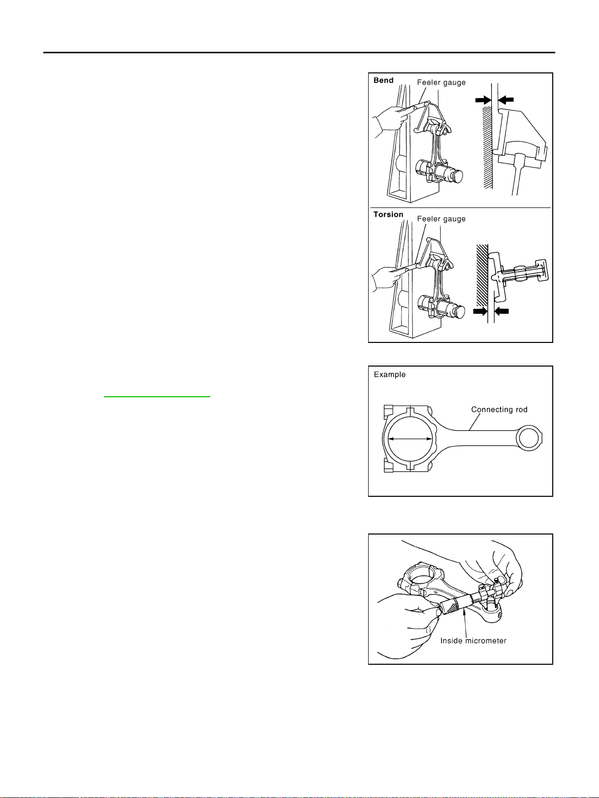
EM-258
[VK45DE]
CYLINDER BLOCK
Revision: 2004 November 2004 FX35/FX45
CONNECTING ROD BEND AND TORSION
● Check with connecting rod aligner.
● If it exceeds the limit, replace connecting rod assembly.
CONNECTING ROD BIG END DIAMETER
● Install connecting rod cap without installing connecting rod bear-
ing, and tightening connecting rod bolts to the specified torque.
Refer to EM-244, "
ASSEMBLY" for the tightening procedure.
● Measure the inner diameter of connecting rod big end with
inside micrometer.
● If out of the standard, replace connecting rod assembly.
CONNECTING ROD BUSHING OIL CLEARANCE
Connecting Rod Bushing Inner Diameter
Measure the inner diameter of connecting rod bushing with inside
micrometer.
Bend:
Limit : 0.15 mm (0.0059 in) per 100 mm (3.94 in) length
Torsion:
Limit : 0.30 mm (0.0118 in) per 100 mm (3.94 in) length
PBIC2077E
Standard : 55.000 - 55.013 mm (2.1654 - 2.1659 in)
PBIC1641E
Standard : 22.000 - 22.012 mm (0.8661 - 0.8666 in)
PBIC0120E
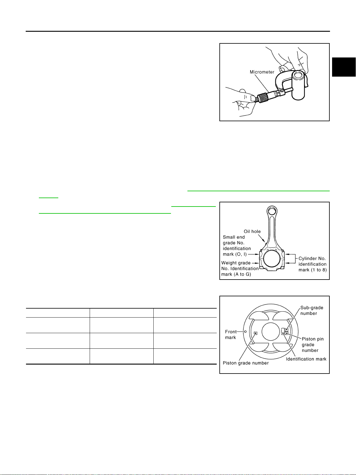
CYLINDER BLOCK
EM-259
[VK45DE]
C
D
E
F
G
H
I
J
K
L
M
A
EM
Revision: 2004 November 2004 FX35/FX45
Piston Pin Outer Diameter
Measure the outer diameter of piston pin with micrometer.
Connecting Rod Bushing Oil Clearance
(Connecting rod bushing oil clearance) = (Connecting rod bushing inner diameter) – (Piston pin outer diame-
ter)
● If the measured value exceeds the limit, replace connecting rod assembly and/or piston and piston pin
assembly.
● If replacing piston and piston pin assembly, refer to EM-260, "PISTON TO CYLINDER BORE CLEAR-
ANCE" .
● If replacing connecting rod assembly, refer to EM-263, "CON-
NECTING ROD BEARING OIL CLEARANCE" to select the
connecting rod bearing.
Factory installed parts grading:
● Service parts apply only to grade “0”.
Unit: mm (in)
*: After installing in connecting rod
CYLINDER BLOCK DISTORTION
● Using scraper, remove gasket on the cylinder block surface, and also remove engine oil, scale, carbon, or
other contamination.
CAUTION:
Be careful not to allow gasket flakes to enter engine oil or engine coolant passages.
Standard : 21.989 - 22.001 mm (0.8657 - 0.8662 in)
PBIC0117E
Standard : 0.005 - 0.017 mm (0.0002 - 0.0007 in)
Limit : 0.030 mm (0.0012 in)
PBIC2164E
Grade 0 1
Connecting rod bushing
inner diameter *
22.000 - 22.006
(0.8661 - 0.8664)
22.006 - 22.012
(0.8664 - 0.8666)
Piston pin hole diameter
21.993 - 21.999
(0.8659- 0.8661)
21.999 - 22.005
(0.8661 - 0.8663)
Piston pin outer diameter
21.989 - 21.995
(0.8657 - 0.8659)
21.995 - 22. 001
(0.8659 - 0.8662)
PBIC2372E
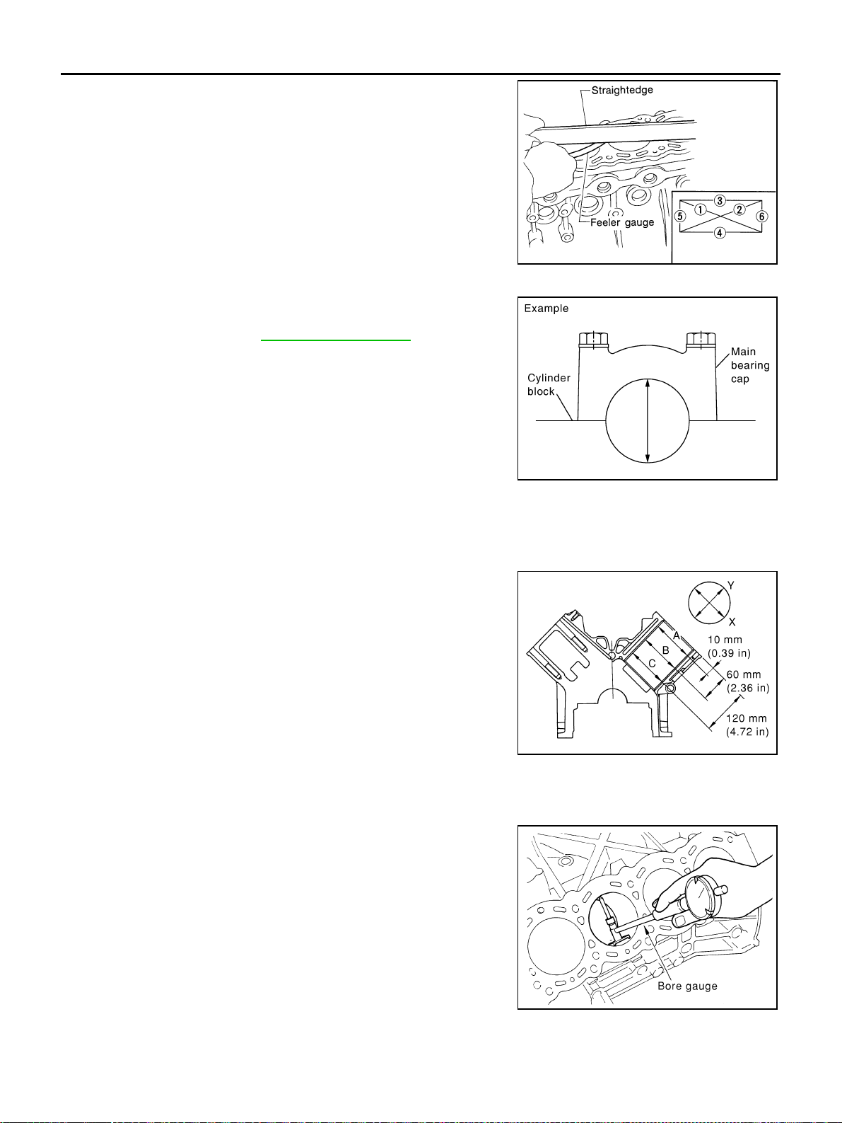
EM-260
[VK45DE]
CYLINDER BLOCK
Revision: 2004 November 2004 FX35/FX45
● Measure the distortion on the cylinder block upper face at some
different points in six directions with straightedge and feeler
gauge.
● If it exceeds the limit, replace cylinder block.
MAIN BEARING HOUSING INNER DIAMETER
● Install main bearing caps and main bearing beam without install-
ing main bearings, and tighten main bearing cap bolts to the
specified torque. Refer to EM-244, "
ASSEMBLY" for the tight-
ening procedure.
● Measure the inner diameter of main bearing housing with bore
gauge.
● If out of the standard, replace cylinder block and main bearing
caps as assembly.
NOTE:
Cylinder block cannot be replaced as single part, because it is
machined together with main bearing caps.
PISTON TO CYLINDER BORE CLEARANCE
Cylinder Bore Inner Diameter
● Using bore gauge, measure cylinder bore for wear, out-of-round
and taper at six different points on each cylinder. (“X” and “Y”
directions at “A”, “B” and “C”) (“Y” is in longitudinal direction of
engine)
● If the measured value exceeds the limit, or if there are scratches
and/or seizure on the cylinder inner wall, hone or re-bore the
inner wall.
● Oversize piston is provided. When using oversize piston, re-
bore cylinder so that the clearance of the piston-to-cylinder bore
satisfies the standard.
CAUTION:
When using oversize piston, use it for all cylinders with
oversize piston rings.
Limit : 0.1 mm (0.004 in)
SEM123C
Standard : 68.944 - 68.968 mm (2.7143 - 2.7153 in)
PBIC1643E
Standard inner diameter:
93.000 - 93.030 mm (3.6614 - 3.6626 in)
Wear limit:
0.2 mm (0.008 in)
Out-of-round (Difference between “X” and “Y”):
0.015 mm (0.0006 in)
Taper limit (Difference between “A” and “C”):
0.01 mm (0.0004 in)
Oversize (OS) : 0.2 mm (0.008 in)
PBIC0123E
PBIC0124E
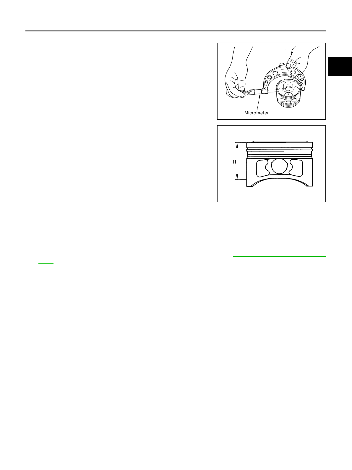
CYLINDER BLOCK
EM-261
[VK45DE]
C
D
E
F
G
H
I
J
K
L
M
A
EM
Revision: 2004 November 2004 FX35/FX45
Piston Skirt Diameter
● Measure outer diameter of piston skirt with micrometer.
● Measure point “H” (Distance from the top): 42 mm (1.65 in)
Piston to Cylinder Bore Clearance
Calculate by piston skirt diameter and cylinder bore inner diameter (direction “X”, position “B”).
(Clearance) = (Cylinder bore inner diameter) – (Piston skirt diameter).
● If it exceeds the limit, replace piston and piston pin assembly. Refer to EM-250, "HOW TO SELECT PIS-
TON" .
Re-Boring Cylinder Bore
1. Cylinder bore size is determined by adding piston to cylinder bore clearance to piston skirt diameter.
2. Install main bearing caps and main bearing beam, and tighten to the specified torque. Otherwise, cylinder
bores may be distorted in final assembly.
3. Cut cylinder bores.
NOTE:
● When any cylinder needs boring, all other cylinders must also be bored.
● Do not cut too much out of cylinder bore at a time. Cut only 0.05 mm (0.0020 in) or so in diameter at a
time.
4. Hone cylinders to obtain specified piston to cylinder bore clearance.
5. Measure finished cylinder bore for out-of-round and taper.
NOTE:
Measurement should be done after cylinder bore cools down.
CRANKSHAFT MAIN JOURNAL DIAMETER
● Measure outer diameter of crankshaft main journals with micrometer.
Standard
: 92.980 - 93.010 mm (3.6606 - 3.6618 in)
PBIC0125E
PBIC0126E
Standard : 0.010 - 0.030 mm (0.0004 - 0.0012 in)
Limit : 0.08 mm (0.0031 in)
Re-bored size calculation: D = A + B - C
where,
D: Bored diameter
A: Piston skirt diameter as measured
B: Piston to cylinder bore clearance (standard value)
C: Honing allowance 0.02 mm (0.0008 in)
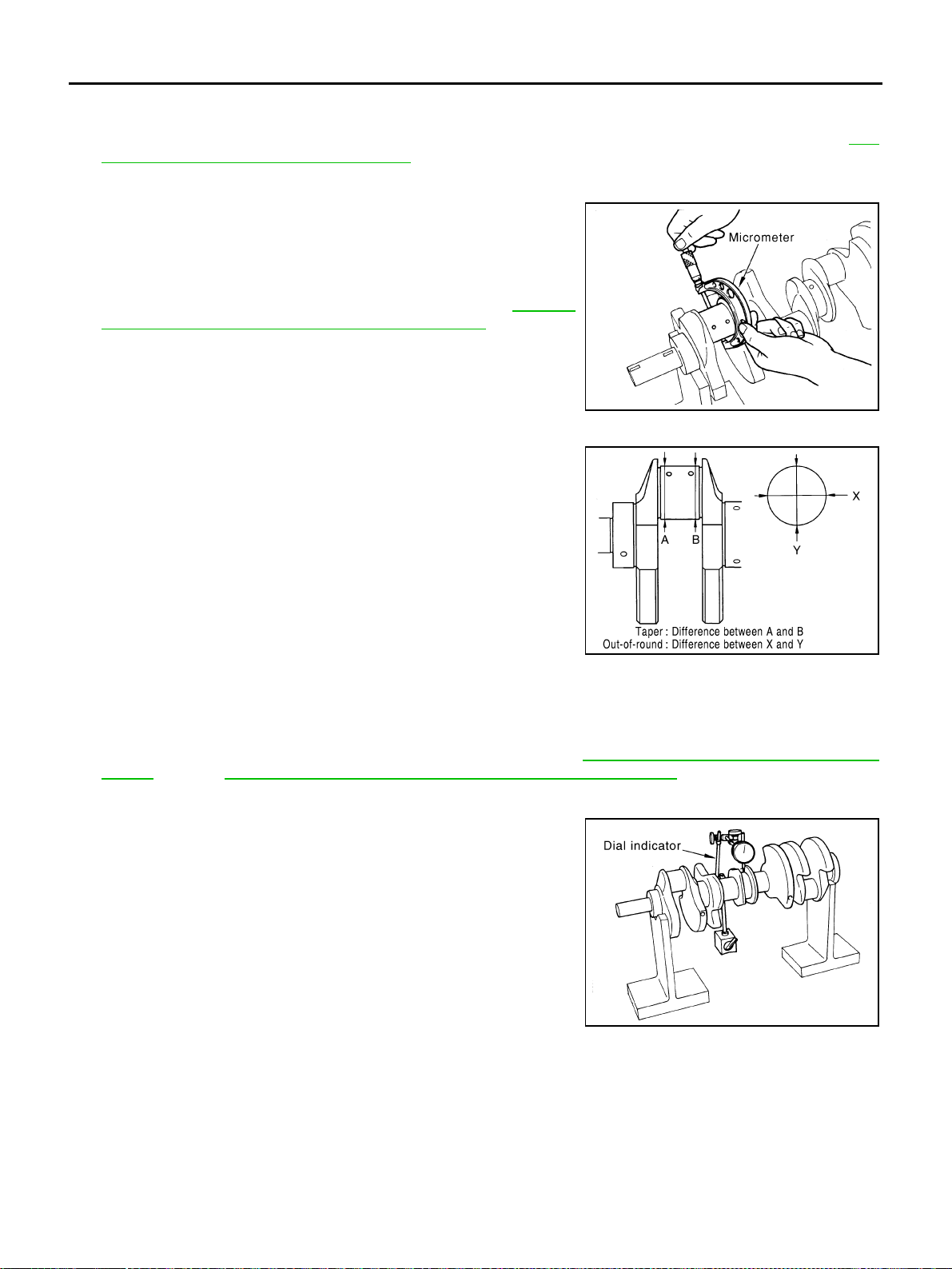
EM-262
[VK45DE]
CYLINDER BLOCK
Revision: 2004 November 2004 FX35/FX45
● If out of the standard, measure the main bearing oil clearance. Then use undersize bearing. Refer to EM-
264, "MAIN BEARING OIL CLEARANCE" .
CRANKSHAFT PIN JOURNAL DIAMETER
● Measure outer diameter of crankshaft pin journal with microme-
ter.
● If out of the standard, measure the connecting rod bearing oil
clearance. Then use undersize bearing. Refer to EM-263,
"CONNECTING ROD BEARING OIL CLEARANCE" .
CRANKSHAFT OUT-OF-ROUND AND TAPER
● Measure the dimensions at four different points shown in the fig-
ure on each main journal and pin journal with micrometer.
● Out-of-round is indicated by the difference in dimensions
between “X” and “Y” at “A” and “B”.
● Taper is indicated by the difference in dimension between “A”
and “B” at “X” and “Y”.
● If the measured value exceeds the limit, correct or replace crankshaft.
● If corrected, measure the bearing oil clearance of the corrected main journal and/or pin journal. Then
select the main bearing and/or connecting rod bearing. Refer to EM-264, "
MAIN BEARING OIL CLEAR-
ANCE" and/or EM-263, "CONNECTING ROD BEARING OIL CLEARANCE" .
CRANKSHAFT RUNOUT
● Place V-block on precise flat table, and support the journals on
the both end of crankshaft.
● Place dial indicator straight up on the No. 3 journal.
● While rotating crankshaft, read the movement of the pointer on
dial indicator. (Total indicator reading)
● If it exceeds the limit, replace crankshaft.
Standard : 63.940 - 63.964 mm (2.5173 - 2.5183 in) dia.
Standard : 51.956 - 51.974 mm (2.0455 - 2.0462 in) dia.
PBIC0127E
Limit:
Out-of-round (Difference between “X” and “Y”)
: 0.015 mm (0.0006 in)
Taper (Difference between “A” and “B”)
: 0.010 mm (0.0004 in)
PBIC1685E
Limit : 0.10 mm (0.004 in)
PBIC2378E
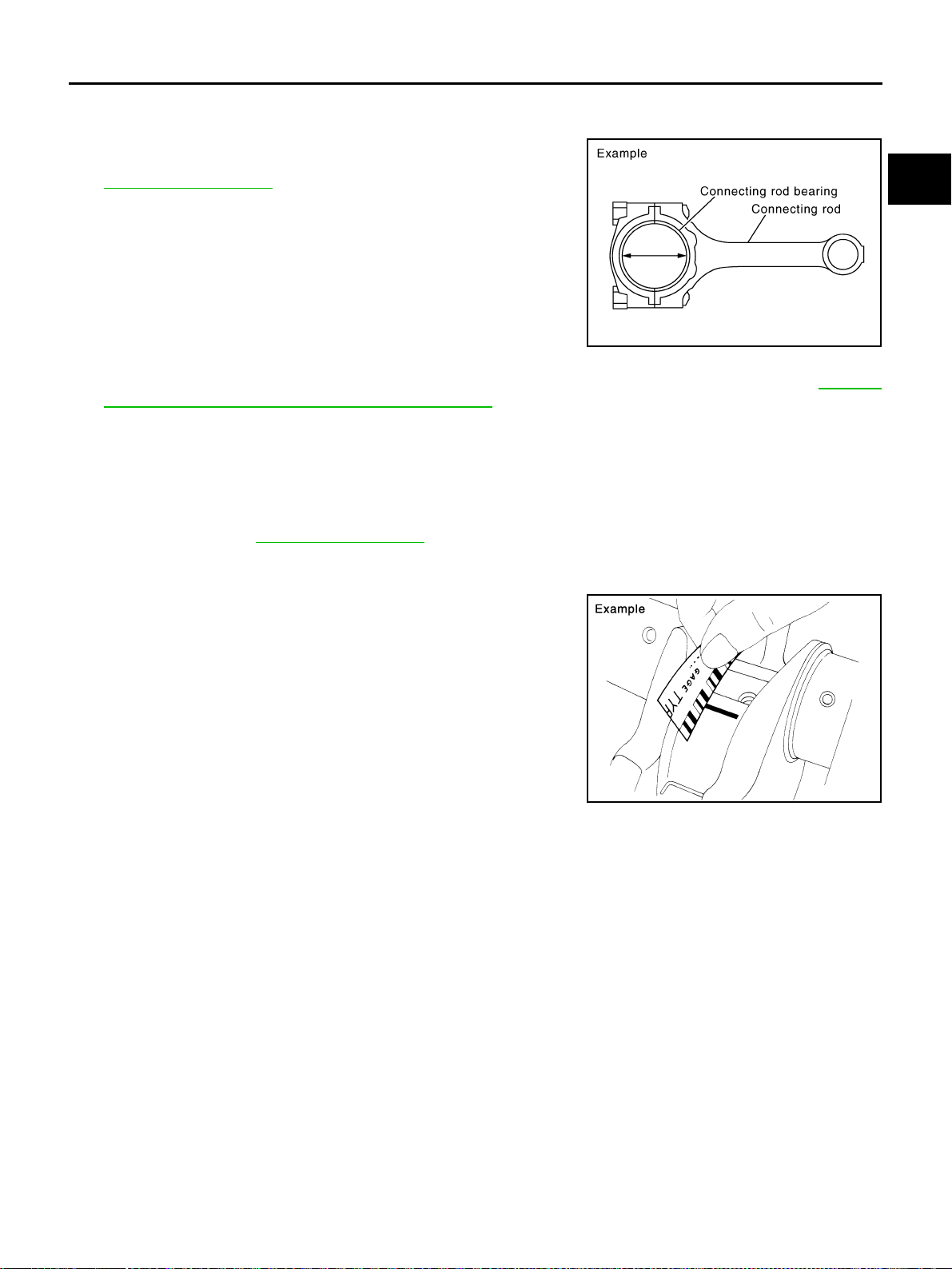
CYLINDER BLOCK
EM-263
[VK45DE]
C
D
E
F
G
H
I
J
K
L
M
A
EM
Revision: 2004 November 2004 FX35/FX45
CONNECTING ROD BEARING OIL CLEARANCE
Method by Calculation
● Install connecting rod bearings to connecting rod and cap, and
tighten connecting rod bolts to the specified torque. Refer to
EM-244, "
ASSEMBLY" for the tightening procedure.
● Measure the inner diameter of connecting rod bearing with
inside micrometer.
(Bearing oil clearance) = (Connecting rod bearing inner diameter) –
(Crankshaft pin journal diameter)
● If clearance exceeds the limit, select proper connecting rod bearing according to connecting rod big end
diameter and crankshaft pin journal diameter to obtain specified bearing oil clearance. Refer to EM-251,
"HOW TO SELECT CONNECTING ROD BEARING" .
Method of Using Plastigage
● Remove oil and dust on crankshaft pin journal and the surfaces of each bearing completely.
● Cut plastigage slightly shorter than the bearing width, and place it in crankshaft axial direction, avoiding oil
holes.
● Install connecting rod bearings to connecting rod and cap, and tighten connecting rod bolts to the speci-
fied torque. Refer to EM-244, "
ASSEMBLY" for the tightening procedure.
CAUTION:
Do not rotate crankshaft.
● Remove connecting rod cap and bearing, and using scale on
plastigage bag, measure the plastigage width.
NOTE:
The procedure when the measured value exceeds the limit is
same as that described in the “Method by Calculation”.
Standard : 0.020 - 0.045 mm (0.0008 - 0.0018 in)
(actual clearance)
Limit : 0.055 mm (0.0022 in)
PBIC1642E
PBIC1149E
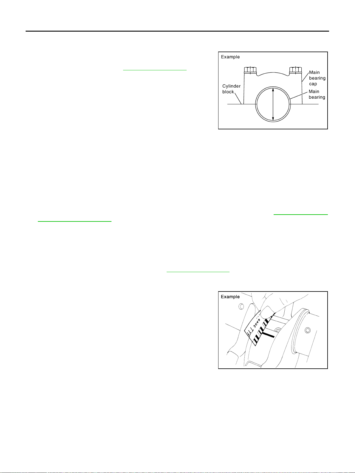
EM-264
[VK45DE]
CYLINDER BLOCK
Revision: 2004 November 2004 FX35/FX45
MAIN BEARING OIL CLEARANCE
Method by Calculation
● Install main bearings to cylinder block and main bearing caps,
and tighten main bearing cap bolts with main bearing beam to
the specified torque. Refer to EM-244, "
ASSEMBLY" for the
tightening procedure.
● Measure the inner diameter of main bearing with bore gauge.
(Bearing clearance) = (Main bearing inner diameter) – (Crankshaft main journal diameter)
● If clearance exceeds the limit, select proper main bearing according to main bearing inner diameter and
crankshaft main journal diameter to obtain specified bearing oil clearance. Refer to EM-252, "
HOW TO
SELECT MAIN BEARING" .
Method of Using Plastigage
● Remove oil and dust on crankshaft main journal and the surfaces of each bearing completely.
● Cut plastigage slightly shorter than the bearing width, and place it in crankshaft axial direction, avoiding oil
holes.
● Install main bearings to cylinder block and main bearing caps, and tighten main bearing bolts with main
bearing beam to the specified torque. Refer to EM-244, "
ASSEMBLY" for the tightening procedure.
CAUTION:
Do not rotate crankshaft.
● Remove main bearing caps and bearings, and using scale on
plastigage bag, measure the plastigage width.
NOTE:
The procedure when the measured value exceeds the limit is
same as that described in the “Method by Calculation”.
PBIC1644E
Standard
No . 1 and 5 journal : 0.001 - 0.011 mm (0.00004 - 0.0004 in)
No. 2, 3 and 4 journal : 0.007 - 0.017 mm (0.0003 - 0.0007 in)
Limit
No . 1 and 5 journal : 0.021 mm (0.0008 in)
No. 2, 3 and 4 journal : 0.027 mm (0.0011 in)
PBIC1149E
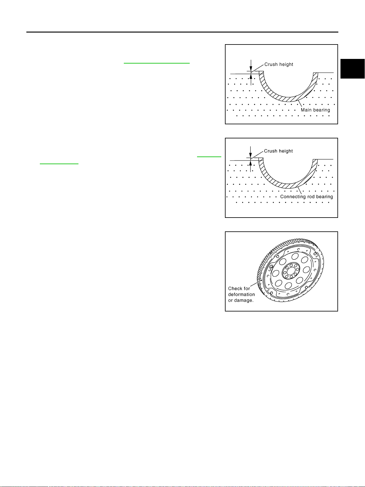
CYLINDER BLOCK
EM-265
[VK45DE]
C
D
E
F
G
H
I
J
K
L
M
A
EM
Revision: 2004 November 2004 FX35/FX45
CRUSH HEIGHT OF MAIN BEARING
● When main bearing cap is removed after being tightened to the
specified torque with main bearings installed, the tip end of bear-
ing must protrude. Refer to EM-244, "
ASSEMBLY" for the
tightening procedure.
● If the standard is not met, replace main bearings.
CRUSH HEIGHT OF CONNECTING ROD BEARING
● When connecting rod bearing cap is removed after being tight-
ened to the specified torque with connecting rod bearings
installed, the tip end of bearing must protrude. Refer to EM-244,
"ASSEMBLY" for the tightening procedure.
● If the standard is not met, replace connecting rod bearings.
DRIVE PLATE
● Check drive plate and signal plate for deformation or cracks.
CAUTION:
● Do not disassemble drive plate.
● Do not place drive plate with signal plate facing down.
● When handling signal plate, take care not to damage or
scratch it.
● Handle signal plate in a manner that prevents it from
becoming magnetized.
● If anything is found, replace drive plate.
Standard : There must be crush height.
SEM502G
Standard : There must be crush height.
PBIC1646E
PBIC2367E
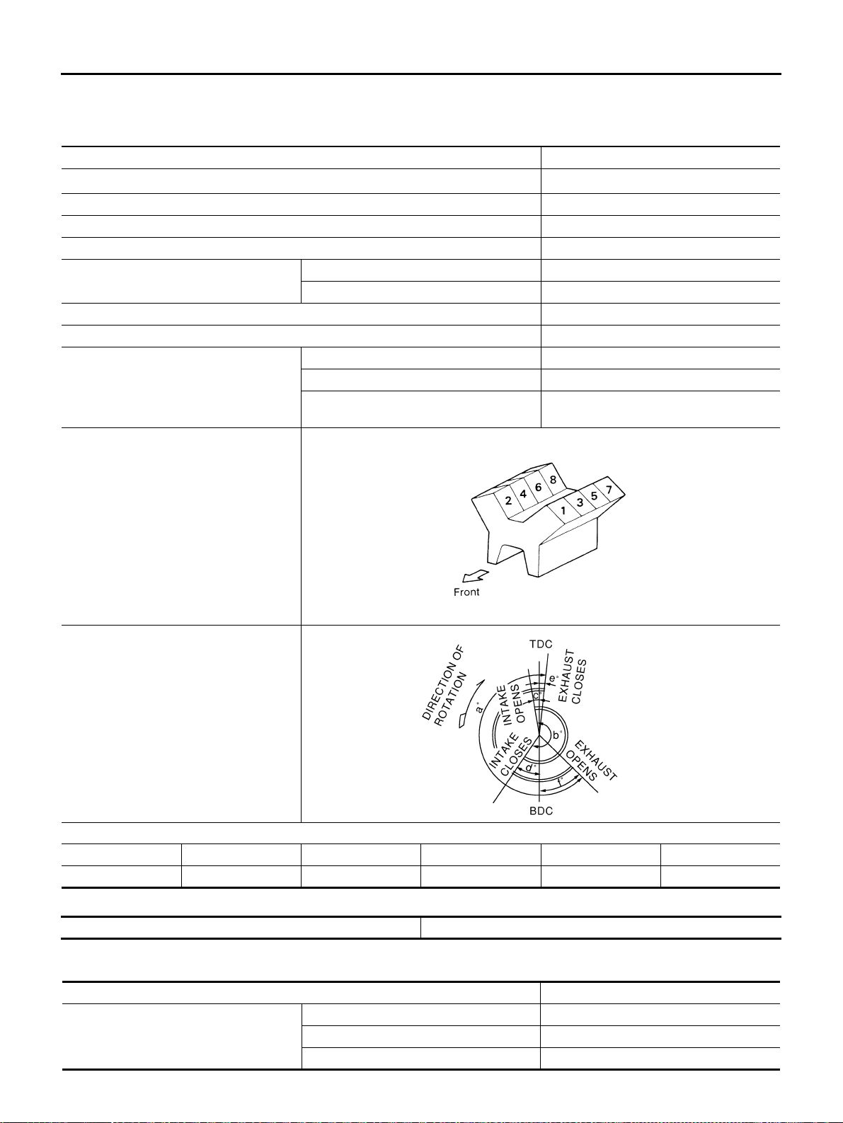
EM-266
[VK45DE]
SERVICE DATA AND SPECIFICATIONS (SDS)
Revision: 2004 November 2004 FX35/FX45
SERVICE DATA AND SPECIFICATIONS (SDS) PFP:00030
Standard and Limit ABS006IX
GENERAL SPECIFICATIONS
DRIVE BELTS
INTAKE MANIFOLD AND EXHAUST MANIFOLD
Unit: mm (in)
Cylinder arrangement V-8
Displacement cm
3
(cu in)
4,494 (274.22)
Bore and stroke mm (in) 93 x 82.7 (3.66 x 3.256)
Valve arrangement DOHC
Firing order 1-8-7-3-6-5-4-2
Number of piston rings
Compression 2
Oil 1
Number of main bearings 5
Compression ratio 10.5
Compression pressure
kPa (kg/cm
2
, psi)/300 rpm
Standard 1,320 (13.5, 191)
Minimum 1,130 (11.5, 164)
Differential limit
between cylinders
98 (1.0, 14)
Cylinder number
Valve timing
Unit: degree
abcdef
228240060048
SEM957C
PBIC0187E
Tension of drive belts Auto adjustment by auto tensioner
Items Limit
Surface distortion
Intake manifold (upper) 0.1 (0.004)
Intake manifold (lower) 0.1 (0.004)
Exhaust manifold 0.3 (0.012)
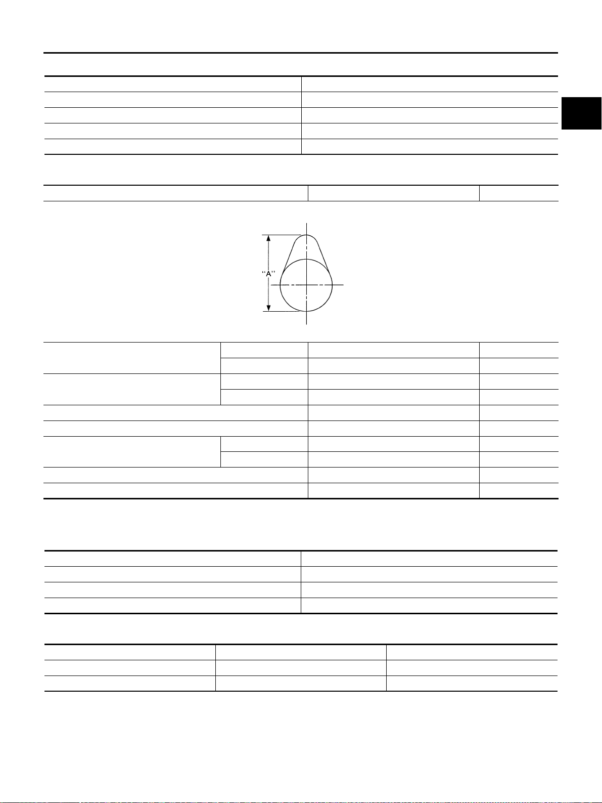
SERVICE DATA AND SPECIFICATIONS (SDS)
EM-267
[VK45DE]
C
D
E
F
G
H
I
J
K
L
M
A
EM
Revision: 2004 November 2004 FX35/FX45
SPARK PLUG
CAMSHAFT AND CAMSHAFT BEARING
Unit: mm (in)
*: Total indicator reading
Valve Lifter
Unit: mm (in)
Valve Clearance
Unit: mm (in)
*: Approximately 20°C (68°F)
Make NGK
Standard type PLFR5A-11
Hot type PLFR4A-11
Cold type PLFR6A-11
Gap (nominal) 1.1 mm (0.043 in)
Items Standard Limit
Camshaft journal clearance
No. 1 0.045 - 0.083 (0.0018 - 0.0033) —
No. 2, 3, 4, 5 0.030 - 0.068 (0.0012 - 0.0027) —
Camshaft journal diameter
No. 1 25.938 - 25.955 (1.0212 - 1.0218) —
No. 2, 3, 4, 5 25.953 - 25.970 (1.0218 - 1.0224) —
Camshaft bracket inner diameter 26.000 - 26.021 (1.0236 - 1.0244) —
Camshaft end play 0.115 - 0.188 (0.0045 - 0.0074) —
Cam height “A”
Intake 44.865 - 45.055 (1.7663 - 1.7738) 0.2 (0.008)
Exhaust 43.925 - 44.115 (1.7293 - 1.7368) 0.2 (0.008)
Camshaft runout [TIR*] — 0.02 (0.0008)
Camshaft sprocket runout [TIR*] — 0.15 (0.059)
SEM671
Items Standard
Valve lifter outer diameter 33.965 - 33.975 (1.3372 - 1.3776)
Valve lifter hole diameter 34.000 - 34.016 (1.3386 - 1.3392)
Valve lifter clearance 0.025 - 0.051 (0.0010 - 0.0020)
Items Hot Cold* (reference data)
Intake 0.304 - 0.416 (0.012 - 0.016) 0.26 - 0.34 (0.010 - 0.013)
Exhaust 0.308 - 0.432 (0.012 - 0.017) 0.29 - 0.37 (0.011 - 0.015)
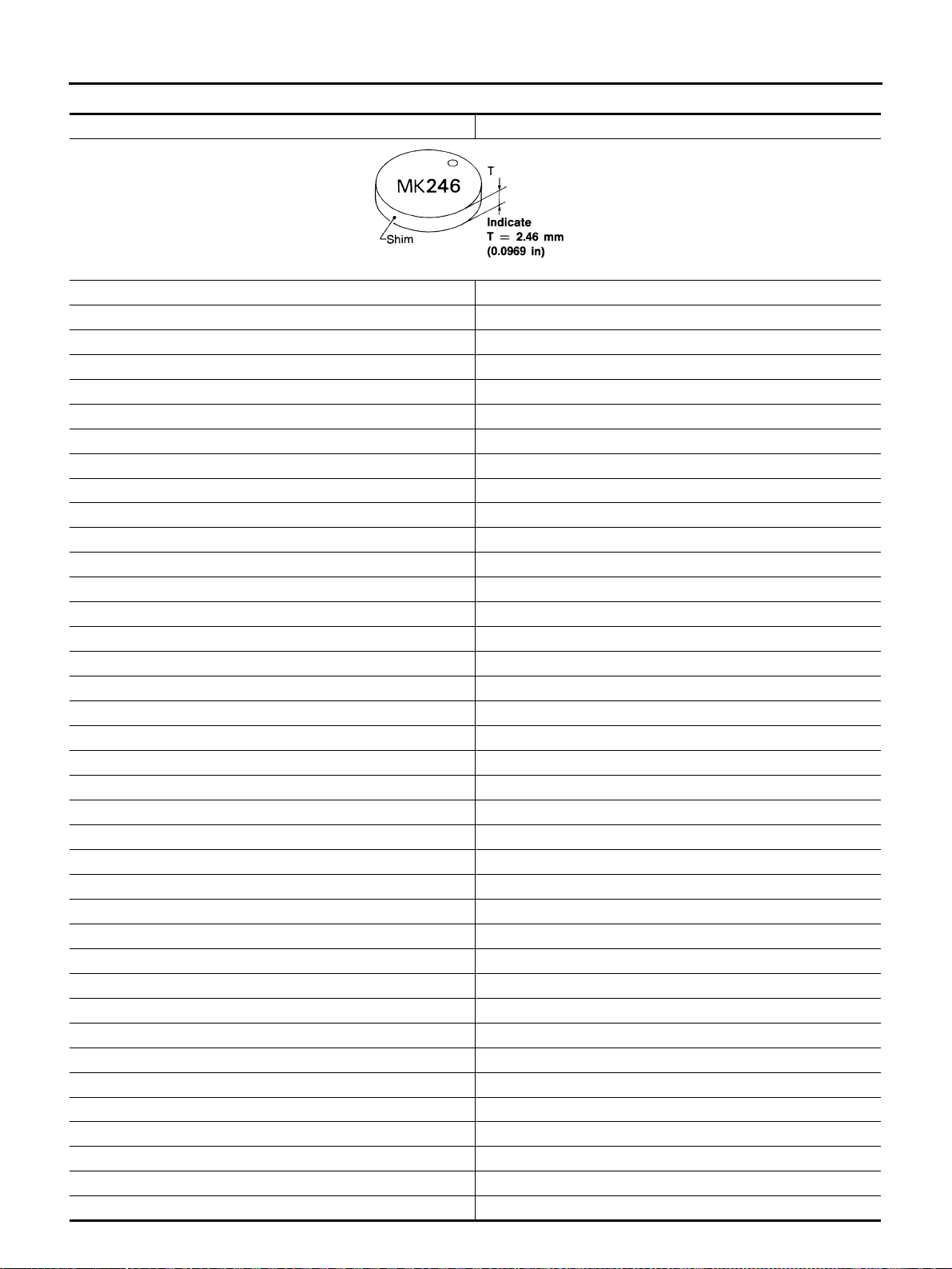
EM-268
[VK45DE]
SERVICE DATA AND SPECIFICATIONS (SDS)
Revision: 2004 November 2004 FX35/FX45
Available Adjusting Shims
Thickness mm (in) Identification (stamped) mark
2.32 (0.0913) 232
2.33 (0.0917) 233
2.34 (0.0921) 234
2.35 (0.0925) 235
2.36 (0.0929) 236
2.37 (0.0933) 237
2.38 (0.0937) 238
2.39 (0.0941) 239
2.40 (0.0945) 240
2.41 (0.0949) 241
2.42 (0.0953) 242
2.43 (0.0957) 243
2.44 (0.0961) 244
2.45 (0.0965) 245
2.46 (0.0969) 246
2.47 (0.0972) 247
2.48 (0.0976) 248
2.49 (0.0980) 249
2.50 (0.0984) 250
2.51 (0.0988) 251
2.52 (0.0992) 252
2.53 (0.0996) 253
2.54 (0.1000) 254
2.55 (0.1004) 255
2.56 (0.1008) 256
2.57 (0.1012) 257
2.58 (0.1016) 258
2.59 (0.1020) 259
2.60 (0.1024) 260
2.61 (0.1028) 261
2.62 (0.1031) 262
2.63 (0.1035) 263
2.64 (0.1039) 264
2.65 (0.1043) 265
2.66 (0.1047) 266
2.67 (0.1051) 267
2.68 (0.1055) 268
2.69 (0.1059) 269
SEM966E
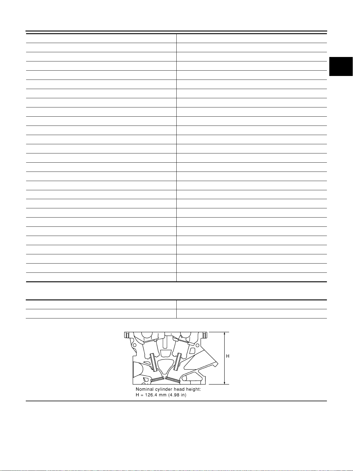
SERVICE DATA AND SPECIFICATIONS (SDS)
EM-269
[VK45DE]
C
D
E
F
G
H
I
J
K
L
M
A
EM
Revision: 2004 November 2004 FX35/FX45
CYLINDER HEAD
Unit: mm (in)
2.70 (0.1063) 270
2.71 (0.1067) 271
2.72 (0.1071) 272
2.73 (0.1075) 273
2.74 (0.1079) 274
2.75 (0.1083) 275
2.76 (0.1087) 276
2.77 (0.1091) 277
2.78 (0.1094) 278
2.79 (0.1098) 279
2.80 (0.1102) 280
2.81 (0.1106) 281
2.82 (0.1110) 282
2.83 (0.1114) 283
2.84 (0.1118) 284
2.85 (0.1122) 285
2.86 (0.1126) 286
2.87 (0.1130) 287
2.88 (0.1134) 288
2.89 (0.1138) 289
2.90 (0.1142) 290
2.91 (0.1146) 291
2.92 (0.1150) 292
2.93 (0.1154) 293
2.94 (0.1157) 294
2.95 (0.1161) 295
Thickness mm (in) Identification (stamped) mark
Items Limit
Surface distortion 0.1 (0.004)
PBIC0183E
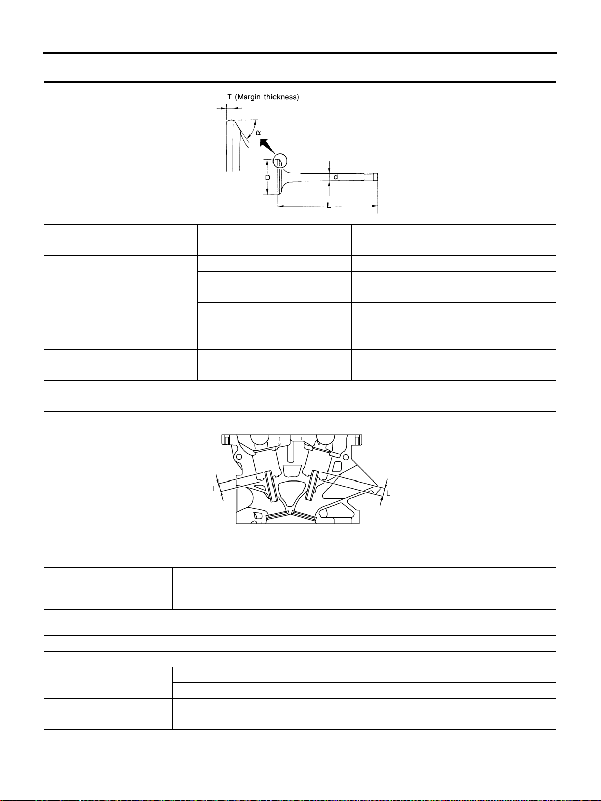
EM-270
[VK45DE]
SERVICE DATA AND SPECIFICATIONS (SDS)
Revision: 2004 November 2004 FX35/FX45
Valve Dimensions
Unit: mm (in)
Valve Guide
Unit: mm (in)
Valve head diameter “D” Intake 36.0 - 36.3 (1.417 - 1.429)
Exhaust 31.2 - 31.5 (1.228 - 1.240)
Valve length “L”
Intake 96.57 (3.8020)
Exhaust 94.50 (3.720)
Valve stem diameter “d”
Intake 5.972 - 5.980 (0.2351 - 0.2354)
Exhaust 5.962 - 5.970 (0.2347 - 0.2350)
Valve seat angle “α”
Intake
45°15′ - 45°45′
Exhaust
Valve margin “T”
Intake 1.15 - 1.45 (0.0453 - 0.0571)
Exhaust 1.85 - 2.15 (0.0728 - 0.0846)
SEM188
Items Standard 0.2 (0.008) Oversize (Service)
Valve guide
Outer diameter
10.023 - 10.034 (0.3946 -
0.3950)
10.223 - 10.234 (0.4025 -
0.4029)
Inner diameter (Finished size) 6.000 - 6.018 (0.2362 - 0.2369)
Cylinder head valve guide hole diameter 9.975 - 9.996 (0.3927 - 0.3935)
10.175 - 10.196 (0.4006 -
0.4014)
Interference fit of valve guide 0.027 - 0.059 (0.0011 - 0.0023)
Items Standard Limit
Valve guide clearance
Intake 0.020 - 0.046 (0.0008 - 0.0018) 0.08 (0.003)
Exhaust 0.030 - 0.056 (0.0012 - 0.0022) 0.1 (0.004)
Projection length “L”
Intake 10.1 - 10.3 (0.398 - 0.406) —
Exhaust 10.0 - 10.4 (0.394 - 0.409) —
PBIC0184E
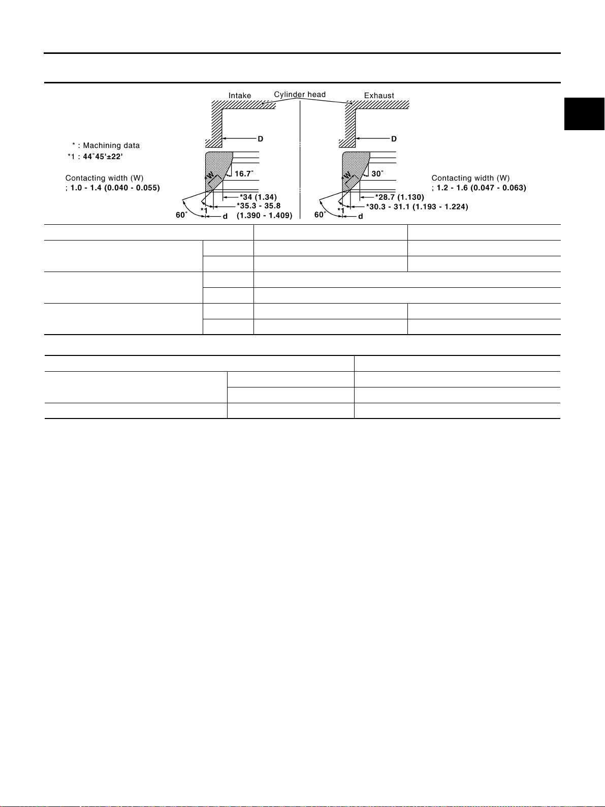
SERVICE DATA AND SPECIFICATIONS (SDS)
EM-271
[VK45DE]
C
D
E
F
G
H
I
J
K
L
M
A
EM
Revision: 2004 November 2004 FX35/FX45
Valve Seat
Unit: mm (in)
Valve Spring
Items Standard Service
Cylinder head seat recess diameter “D”
Intake 37.000 - 37.016 (1.4567 - 1.4573) 37.500 - 37.516 (1.4764 - 1.4770)
Exhaust 32.200 - 32.216 (1.2677 - 1.2683) 32.700 - 32.716 (1.2874 - 1.2880)
Valve seat interference fit
Intake 0.081 - 0.113 (0.0032 - 0.0044)
Exhaust 0.064 - 0.096 (0.0025 - 0.0038)
Valve seat outer diameter “d”
Intake 37.097 - 37.113 (1.4605 - 1.4611) 37.597 - 37.613 (1.4802 - 1.4808)
Exhaust 32.280 - 32.296 (1.2709 - 1.2715) 32.780 - 32.796 (1.2905 - 1.2912)
PBIC2379E
Free height mm (in) 46.35 - 46.85 (1.8247 - 1.8444)
Pressure N (kg, lb) at height mm (in)
Installation 165 - 189 (16.8 - 19.3, 37 - 42) at 33.8 (1.331)
Valve open 290 - 330 (29.6 - 33.7, 65 - 74) at 24.4 (0.961)
Out-of-square mm (in) Limit 2.0 (0.079)
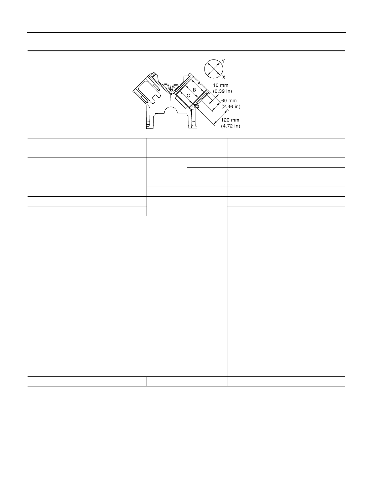
EM-272
[VK45DE]
SERVICE DATA AND SPECIFICATIONS (SDS)
Revision: 2004 November 2004 FX35/FX45
CYLINDER BLOCK
Unit: mm (in)
Surface distortion Limit 0.1 (0.004)
Main bearing housing inner diameter Standard 68.944 - 68.968 (2.7143 - 2.7153)
Cylinder bore inner diameter
Standard
Grade No. 1 93.000 - 93.010 (3.6614 - 3.6618)
Grade No. 2 93.010 - 93.020 (3.6618 - 3.6622)
Grade No. 3 93.020 - 93.030 (3.6622 - 3.6626)
Wear limit 0.2 (0.008)
Out-of-round (Difference between “X” and “Y”)
Limit
0.015 (0.0006)
Taper (Difference between “A” and “C”) 0.01 (0.0004)
Main bearing housing inner diameter (Without bearing)
Grade No. A
Grade No. B
Grade No. C
Grade No. D
Grade No. E
Grade No. F
Grade No. G
Grade No. H
Grade No. J
Grade No. K
Grade No. L
Grade No. M
Grade No. N
Grade No. P
Grade No. R
Grade No. S
Grade No. T
Grade No. U
Grade No. V
Grade No. W
Grade No. X
Grade No. Y
Grade No. 1
Grade No. 2
68.944 - 68.945 (2.7143 - 2.7144)
68.945 - 68.946 (2.7144 - 2.7144)
68.946 - 68.947 (2.7144 - 2.7144)
68.947 - 68.948 (2.7144 - 2.7145)
68.948 - 68.949 (2.7145 - 2.7145)
68.949 - 68.950 (2.7145 - 2.7146)
68.950 - 68.951 (2.7146 - 2.7146)
68.951 - 68.952 (2.7146 - 2.7146)
68.952 - 68.953 (2.7146 - 2.7147)
68.953 - 68.954 (2.7147 - 2.7147)
68.954 - 68.955 (2.7147 - 2.7148)
68.955 - 68.956 (2.7148 - 2.7148)
68.956 - 68.957 (2.7148 - 2.7148)
68.957 - 68.958 (2.7148 - 2.7149)
68.958 - 68.959 (2.7149 - 2.7149)
68.959 - 68.960 (2.7149 - 2.7150)
68.960 - 68.961 (2.7150 - 2.7150)
68.961 - 68.962 (2.7150 - 2.7150)
68.962 - 68.963 (2.7150 - 2.7151)
68.963 - 68.964 (2.7151 - 2.7151)
68.964 - 68.965 (2.7151 - 2.7152)
68.965 - 68.966 (2.7152 - 2.7152)
68.966 - 68.967 (2.7152 - 2.7152)
68.967 - 68.968 (2.7152 - 2.7153)
Difference in inner diameter between cylinders Standard Less than 0.03 (0.0012)
PBIC0123E
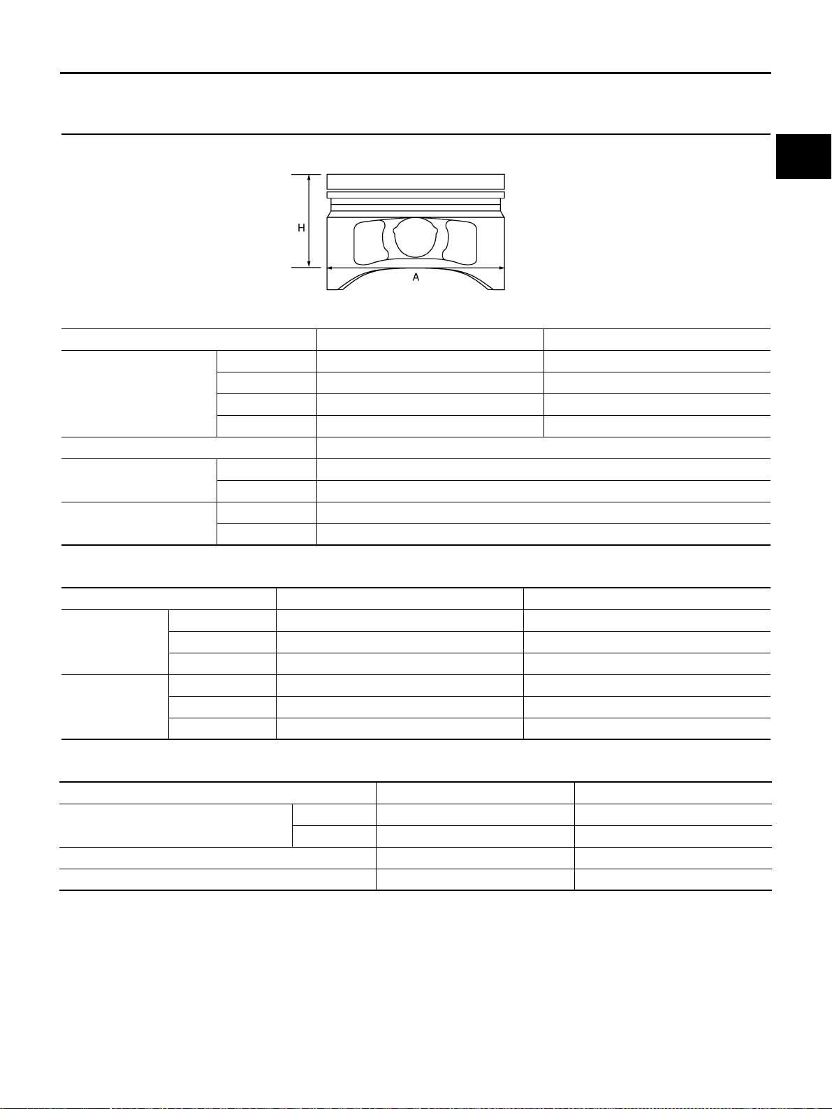
SERVICE DATA AND SPECIFICATIONS (SDS)
EM-273
[VK45DE]
C
D
E
F
G
H
I
J
K
L
M
A
EM
Revision: 2004 November 2004 FX35/FX45
PISTON, PISTON RING AND PISTON PIN
Available Piston
Unit: mm (in)
Piston Ring
Unit: mm (in)
Piston Pin
Unit: mm (in)
Items Standard 0.20 (0.008) Oversize
Piston skirt diameter “A”
Grade No. 1 92.980 - 92.990 (3.6606 - 3.6610) —
Grade No. 2 92.990 - 93.000 (3.6610 - 3.6614) —
Grade No. 3 93.000 - 93.010 (3.6614 - 3.6618) —
Service — 93.180 - 93.210 (3.6685 - 3.6697)
“H” dimension 42 (1.65)
Piston pin hole diameter
Grade No. 0 21.993 - 21.999 (0.8659 - 0.8661)
Grade No. 1 21.999 - 22.005 (0.8661 - 0.8663)
Piston to cylinder bore
clearance
Standard 0.010 - 0.030 (0.0004 - 0.0012)
Limit 0.08 (0.0031)
PBIC0188E
Standard Limit
Side clearance
Top 0.045 - 0.080 (0.0018 - 0.0031) 0.11 (0.0043)
2nd 0.030 - 0.070 (0.0012 - 0.0028) 0.1 (0.004)
Oil ring 0.065 - 0.135 (0.0026 - 0.0053) —
End gap
Top 0.22 - 0.32 (0.0087 - 0.0126) 0.56 (0.0220)
2nd 0.22 - 0.32 (0.0087 - 0.0126) 0.56 (0.0220)
Oil (rail ring) 0.20 - 0.60 (0.0079 - 0.0236) 0.96 (0.0378)
Items Standard Limit
Piston pin outer diameter
Grade No. 0 21.989 - 21.995 (0.8657 - 0.8659) —
Grade No. 1 21.995 - 22.001 (0.8659 - 0.8662) —
Piston to piston pin oil clearance 0.002 - 0.006 (0.0001 - 0.0002) —
Connecting rod bushing oil clearance 0.005 - 0.017 (0.0002 - 0.0007) 0.030 (0.0012)

EM-274
[VK45DE]
SERVICE DATA AND SPECIFICATIONS (SDS)
Revision: 2004 November 2004 FX35/FX45
CONNECTING ROD
Unit: mm (in)
*: After installing in connecting rod
Items Standard Limit
Center distance 146.95 - 147.05 (5.79 - 5.79) —
Bend [per 100 (3.94)] — 0.15 (0.0059)
Torsion [per 100 (3.94)] — 0.30 (0.0118)
Connecting rod bushing inner diameter*
Grade No. 0 22.000 - 22.006 (0.8661 - 0.8664) —
Grade No. 1 22.006 - 22.012 (0.8664 - 0.8666) —
Connecting rod big end diameter (without bearing) 55.000 - 55.013 (2.1654 - 2.1659) —
Side clearance 0.20 - 0.35 (0.0079 - 0.0138) 0.40 (0.0157)
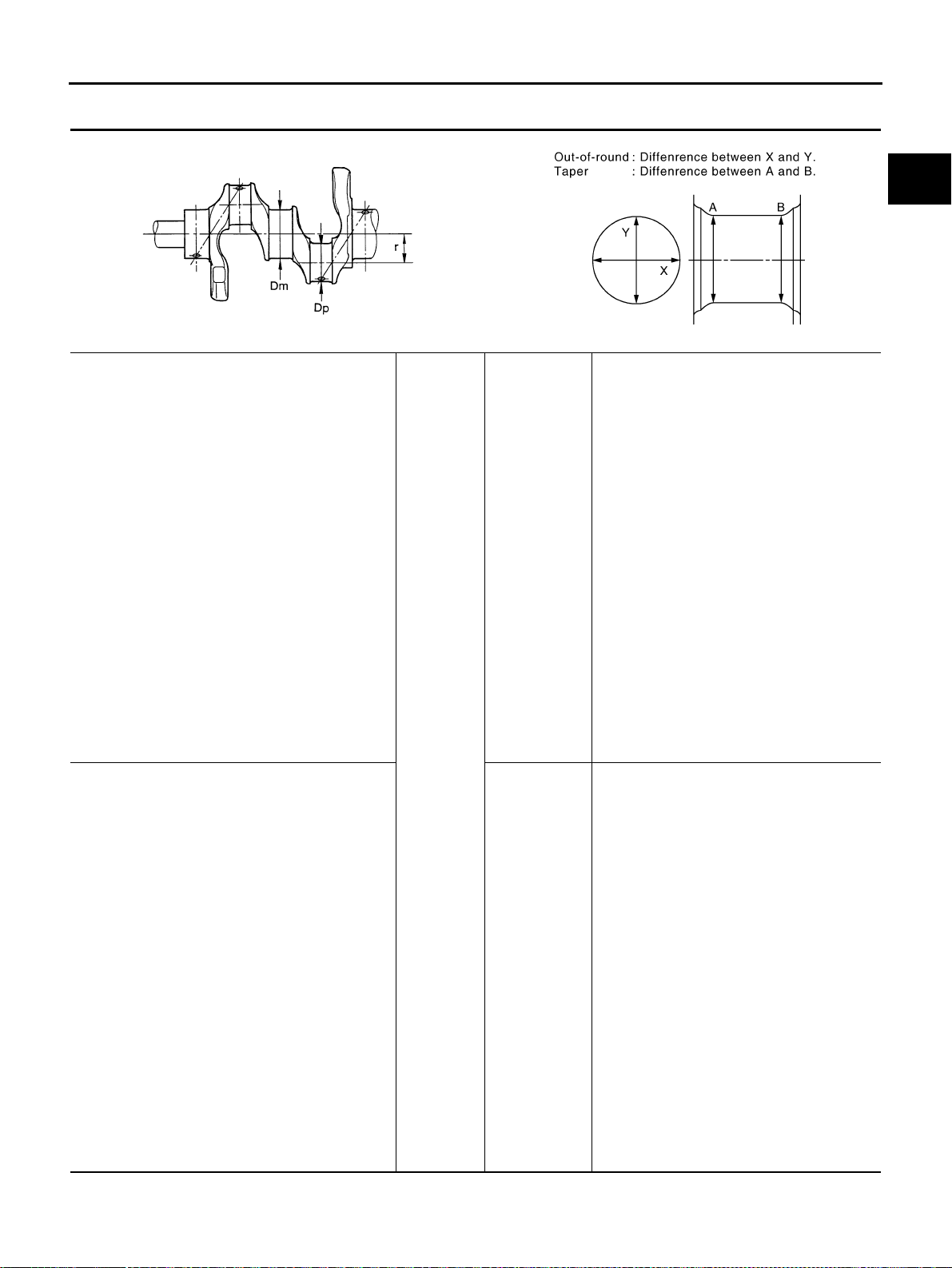
SERVICE DATA AND SPECIFICATIONS (SDS)
EM-275
[VK45DE]
C
D
E
F
G
H
I
J
K
L
M
A
EM
Revision: 2004 November 2004 FX35/FX45
CRANKSHAFT
Unit: mm (in)
Main journal diameter “Dm” (No. 1 and 5 journal)
Standard
Grade No. G
Grade No. H
Grade No. J
Grade No. K
Grade No. L
Grade No. M
Grade No. N
Grade No. P
Grade No. R
Grade No. S
Grade No. T
Grade No. U
Grade No. V
Grade No. W
Grade No. X
Grade No. Y
Grade No. 1
Grade No. 2
Grade No. 3
Grade No. 4
Grade No. 5
Grade No. 6
Grade No. 7
Grade No. 9
63.963 - 63.964 (2.5182 - 2.5183)
63.962 - 63.963 (2.5182 - 2.5182)
63.961 - 63.962 (2.5181 - 2.5182)
63.960 - 63.961 (2.5181 - 2.5181)
63.959 - 63.960 (2.5181 - 2.5181)
63.958 - 63.959 (2.5180 - 2.5181)
63.957 - 63.958 (2.5180 - 2.5180)
63.956 - 63.957 (2.5179 - 2.5180)
63.955 - 63.956 (2.5179 - 2.5179)
63.954 - 63.955 (2.5179 - 2.5179)
63.953 - 63.954 (2.5178 - 2.5179)
63.952 - 63.953 (2.5178 - 2.5178)
63.951 - 63.952 (2.5178 - 2.5178)
63.950 - 63.951 (2.5177 - 2.5178)
63.949 - 63.950 (2.5177 - 2.5177)
63.948 - 63.949 (2.5176 - 2.5177)
63.947 - 63.948 (2.5176 - 2.5176)
63.946 - 63.947 (2.5176 - 2.5176)
63.945 - 63.946 (2.5175 - 2.5176)
63.944 - 63.945 (2.5175 - 2.5175)
63.943 - 63.944 (2.5174 - 2.5175)
63.942 - 63.943 (2.5174 - 2.5174)
63.941 - 63.942 (2.5174 - 2.5174)
63.940 - 63.941 (2.5173 - 2.5174)
Main journal diameter “Dm” (No. 2, 3 and 4 journal)
Grade No. A
Grade No. B
Grade No. C
Grade No. D
Grade No. E
Grade No. F
Grade No. G
Grade No. H
Grade No. J
Grade No. K
Grade No. L
Grade No. M
Grade No. N
Grade No. P
Grade No. R
Grade No. S
Grade No. T
Grade No. U
Grade No. V
Grade No. W
Grade No. X
Grade No. Y
Grade No. 1
Grade No. 2
63.963 - 63.964 (2.5182 - 2.5183)
63.962 - 63.963 (2.5182 - 2.5182)
63.961 - 63.962 (2.5181 - 2.5182)
63.960 - 63.961 (2.5181 - 2.5181)
63.959 - 63.960 (2.5181 - 2.5181)
63.958 - 63.959 (2.5180 - 2.5181)
63.957 - 63.958 (2.5180 - 2.5180)
63.956 - 63.957 (2.5179 - 2.5180)
63.955 - 63.956 (2.5179 - 2.5179)
63.954 - 63.955 (2.5179 - 2.5179)
63.953 - 63.954 (2.5178 - 2.5179)
63.952 - 63.953 (2.5178 - 2.5178)
63.951 - 63.952 (2.5178 - 2.5178)
63.950 - 63.951 (2.5177 - 2.5178)
63.949 - 63.950 (2.5177 - 2.5177)
63.948 - 63.949 (2.5176 - 2.5177)
63.947 - 63.948 (2.5176 - 2.5176)
63.946 - 63.947 (2.5176 - 2.5176)
63.945 - 63.946 (2.5175 - 2.5176)
63.944 - 63.945 (2.5175 - 2.5175)
63.943 - 63.944 (2.5174 - 2.5175)
63.942 - 63.943 (2.5174 - 2.5174)
63.941 - 63.942 (2.5174 - 2.5174)
63.940 - 63.941 (2.5173 - 2.5174)
SEM645 PBIC1686E

EM-276
[VK45DE]
SERVICE DATA AND SPECIFICATIONS (SDS)
Revision: 2004 November 2004 FX35/FX45
*: Total indicator reading
Pin journal diameter “Dp”
Grade No. 0 51.968 - 51.974 (2.0460 - 2.0462)
Grade No. 1 51.962 - 51.968 (2.0457 - 2.0460)
Grade No. 2 51.956 - 51.962 (2.0455 - 2.0457)
Center distance “r” 41.31 - 41.39 (1.6264 - 1.6295)
Out-of-round (Difference between “X” and “Y”) Limit 0.015 (0.0006)
Taper (Difference between “A” and “B”) Limit 0.010 (0.0004)
Runout [TIR*] Limit 0.10 (0.004)
Crankshaft end play
Standard 0.10 - 0.25 (0.0039 - 0.0098)
Limit 0.30 (0.0118)
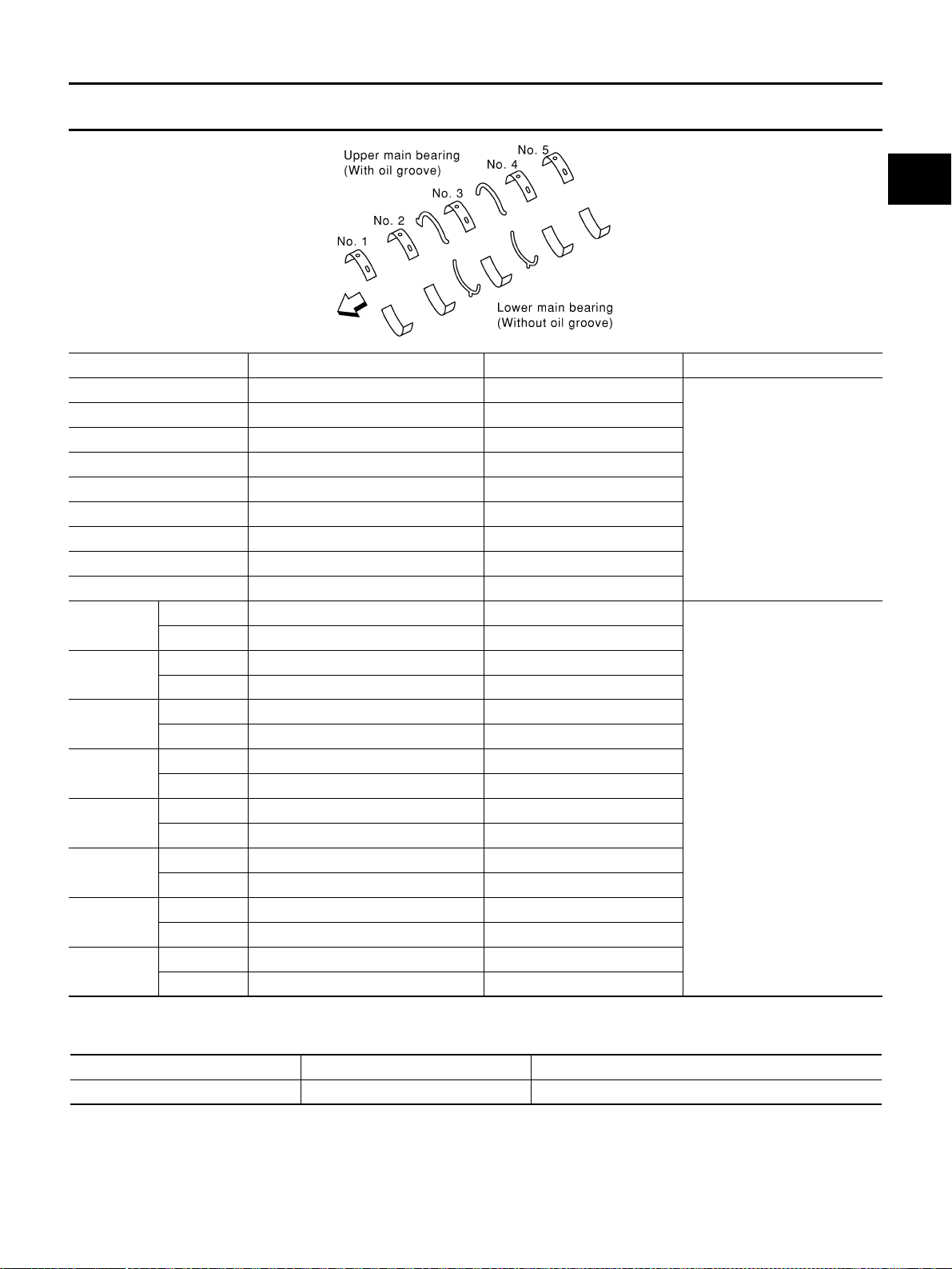
SERVICE DATA AND SPECIFICATIONS (SDS)
EM-277
[VK45DE]
C
D
E
F
G
H
I
J
K
L
M
A
EM
Revision: 2004 November 2004 FX35/FX45
MAIN BEARING
Unit: mm (in)
Undersize
Unit: mm (in)
Grade number Thickness Identification color Remarks
0 2.483 - 2.486 (0.0978 - 0.0979) Black
Grade and color are the same
for upper and lower bearings.
1 2.486 - 2.489 (0.0979 - 0.0980) Brown
2 2.489 - 2.492 (0.0980 - 0.0981) Green
3 2.492 - 2.495 (0.0981 - 0.0982) Yellow
4 2.495 - 2.498 (0.0982 - 0.0983) Blue
5 2.498 - 2.501 (0.0983 - 0.0985) Pink
6 2.501 - 2.504 (0.0985 - 0.0986) Purple
7 2.504 - 2.507 (0.0986 - 0.0987) White
8 2.507 - 2.510 (0.0987 - 0.0988) Red
01
UPR 2.483 - 2.486 (0.0978 - 0.0979) Black
Grade and color are different
for upper and lower bearings.
LWR 2.486 - 2.489 (0.0979 - 0.0980) Brown
12
UPR 2.486 - 2.489 (0.0979 - 0.0980) Brown
LWR 2.489 - 2.492 (0.0980 - 0.0981) Green
23
UPR 2.489 - 2.492 (0.0980 - 0.0981) Green
LWR 2.492 - 2.495 (0.0981 - 0.0982) Yellow
34
UPR 2.492 - 2.495 (0.0981 - 0.0982) Yellow
LWR 2.495 - 2.498 (0.0982 - 0.0983) Blue
45
UPR 2.495 - 2.498 (0.0982 - 0.0983) Blue
LWR 2.498 - 2.501 (0.0983 - 0.0985) Pink
56
UPR 2.498 - 2.501 (0.0983 - 0.0985) Pink
LWR 2.501 - 2.504 (0.0985 - 0.0986) Purple
67
UPR 2.501 - 2.504 (0.0985 - 0.0986) Purple
LWR 2.504 - 2.507 (0.0986 - 0.0987) White
78
UPR 2.504 - 2.507 (0.0986 - 0.0987) White
LWR 2.507 - 2.510 (0.0987 - 0.0988) Red
PBIC0189E
Undersize Thickness Main journal diameter
0.25 (0.0098) 2.618 - 2.626 (0.1031 - 0.1034) Grind so that bearing clearance is the specified value.
EM-278
[VK45DE]
SERVICE DATA AND SPECIFICATIONS (SDS)
Revision: 2004 November 2004 FX35/FX45
Main Bearing Oil Clearance
Unit: mm (in)
CONNECTING ROD BEARING
Unit: mm (in)
Undersize
Unit: mm (in)
Connecting Rod Bearing Oil Clearance
Unit: mm (in)
Main bearing oil clearance
Standard
No.1 and 5 0.001 - 0.011 (0.00004 - 0.0004)
No.2, 3 and 4 0.007 - 0.017 (0.0003 - 0.0007)
Limit
No.1 and 5 0.021 (0.0008)
No.2, 3 and 4 0.027 (0.0011)
Grade number Thickness Identification color (mark)
0 1.500 - 1.503 (0.0591 - 0.0592) No color
1 1.503 - 1.506 (0.0592 - 0.0593) Brown
2 1.506 - 1.509 (0.0593 - 0.0594) Green
Undersize Thickness Pin journal diameter
0.25 (0.0098) 1.626 - 1.634 (0.0640 - 0.0643) Grind so that bearing clearance is the specified value.
Connecting rod bearing oil clearance
Standard 0.020 - 0.045 (0.0008 - 0.0018)
Limit 0.055 (0.0022)