Loading ...
Loading ...
Loading ...
EM-128
[VQ35DE]
CYLINDER BLOCK
Revision: 2004 November 2004 FX35/FX45
c. Turn all bolts another “90” degrees clockwise (Angle tightening).
CAUTION:
Use an angle wrench [SST: KV10112100 (BT8653-A)] to
check tightening angle. Do not make judgment by visual
inspection.
● After installing mounting bolts, make sure that crankshaft can
be rotated smoothly by hand.
● Check crankshaft end play. Refer to EM-136, "CRANKSHAFT
END PLAY" .
11. Inspect outer diameter of connecting rod bolt. Refer to EM-144,
"CONNECTING ROD BOLT OUTER DIAMETER" .
12. Install piston to connecting rod.
a. Using a snap ring pliers (commercial service tool), install a new snap ring to the groove of the piston rear
side.
● Insert it fully into groove to install.
b. Install piston to connecting rod.
● Using an industrial drier or similar tool, heat piston until piston pin can be pushed in by hand without
excess force [approx. 60 to 70 °C (140 to 158 °F)]. From the front to the rear, insert piston pin into pis-
ton and connecting rod.
● Assemble so that the front mark on the piston crown and the
cylinder number on connecting rod are positioned as shown in
the figure.
c. Install a new snap ring to the groove of the piston front side.
● Insert it fully into groove to install.
● After installing, make sure connecting rod moves smoothly.
13. Using a piston ring expander (commercial service tool), install piston rings.
CAUTION:
Be careful not to damage piston.
● If there is stamped mark on ring, mount it with marked side
up.
NOTE:
If there is no stamp on ring, no specific orientation is required
for installation.
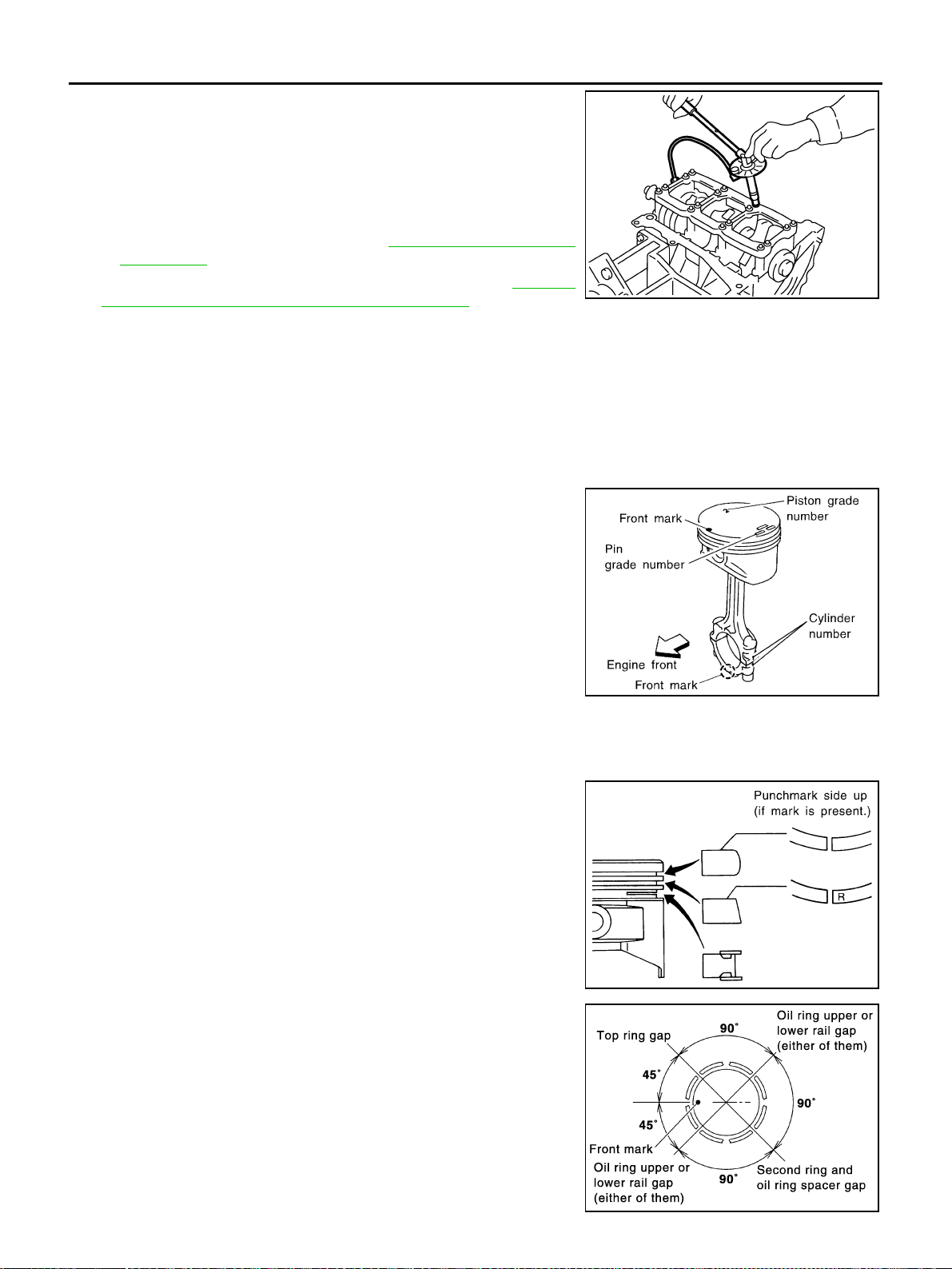
● Position each ring with the gap as shown in the figure refer-
ring to the piston front mark.
PBIC0921E
SEM838F
Stamped mark:
Top ring : —
Second ring : “R”
SEM757G
PBIC0808E
Loading ...
Loading ...
Loading ...