Loading ...
Loading ...
Loading ...
CAMSHAFT
EM-217
[VK45DE]
C
D
E
F
G
H
I
J
K
L
M
A
EM
Revision: 2004 November 2004 FX35/FX45
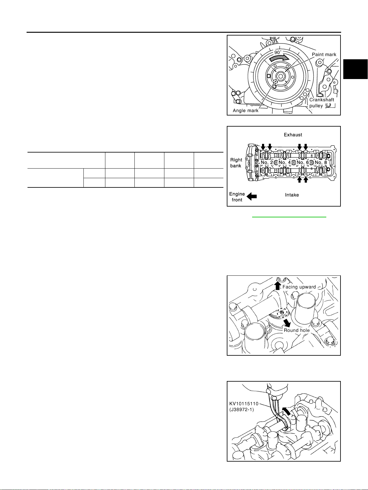
d. Rotate crankshaft pulley clockwise (when view from engine
front) by 90 degrees from the position of No. 3 cylinder compres-
sion TDC to align No. 6 cylinder at TDC of its compression
stroke.
● By referring to the figure, measure valve clearances at loca-
tions marked “×” as shown in the table below.
● No. 6 cylinder compression TDC
4. For measured value are out of the standard, perform adjustment. Refer to EM-217, "
ADJUSTMENT" .
ADJUSTMENT
CAUTION:
● Adjust valve clearance while engine is cold.
● After adjusting, make sure that the valve clearance is within the standard while engine is hot.
1. Thoroughly wipe off engine oil around adjusting shim using rag.
2. Rotate crankshaft to position cam nose on camshaft of valve that must be adjusted upward.
3. Using small screwdriver, turn the round hole of adjusting shim in
the direction of the arrow.
CAUTION:
perform (the above procedure) during camshaft do not con-
tact with adjusting shim.
4. Install lifter stopper [SST: 10115120 (J38972-2)] as follows:
a. Except exhaust side of No. 7 and No. 8 cylinder;
i. Place camshaft pliers (SST) around camshaft as shown in the
figure.
ii. Rotate camshaft pliers so that valve lifter is pushed down.
CAUTION:
Be careful not to damage cam surface, valve lifter and cylin-
der head with camshaft pliers.
PBIC2346E
Measuring position (right bank)
No. 2
CYL.
No. 4
CYL.
No. 6
CYL.
No. 8
CYL.
No. 6 cylinder at TDC
EXH × ×
INT ×
PBIC0824E
PBIC0047E
PBIC2276E
Loading ...
Loading ...
Loading ...