Loading ...
Loading ...
Loading ...
CAMSHAFT
EM-89
[VQ35DE]
C
D
E
F
G
H
I
J
K
L
M
A
EM
Revision: 2004 November 2004 FX35/FX45
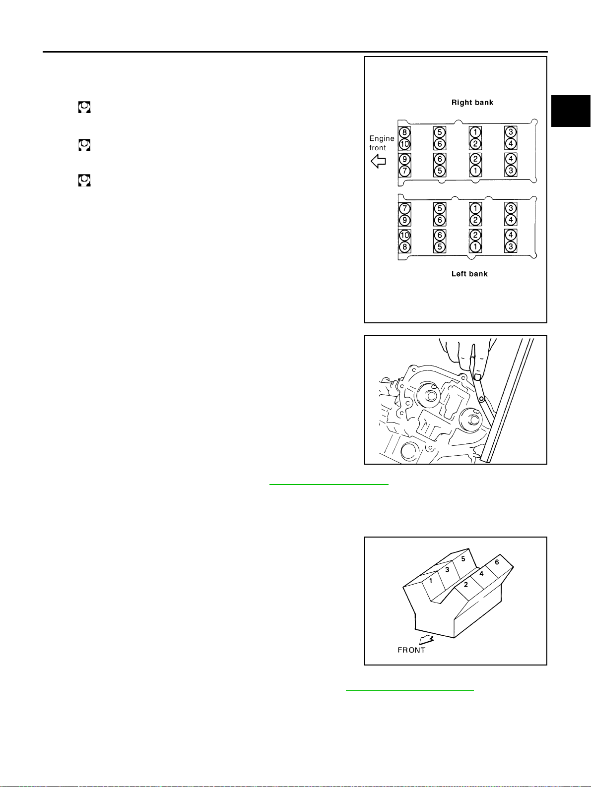
5. Tighten camshaft brackets in the following steps, in numerical
order as shown in the figure.
a. Tighten No. 7 to 10, then tighten No. 1 to 6 in order as shown.
b. Tighten all bolts in numerical order as shown.
c. Tighten all bolts in the numerical order as shown.
CAUTION:
After tightening mounting bolts of No. 1 camshaft brackets
(No. 1), be sure to wipe off excessive liquid gasket from the
parts list below.
● Mating surface of rocker cover
● Mating surface of rear timing chain case
6. Measure difference in levels between front end faces of No. 1
camshaft bracket and cylinder head.
● If measurement is outside the specified range, re-install cam-
shaft and camshaft bracket.
7. Inspect and adjust valve clearance. Refer to EM-89, "
Valve Clearance" .
8. Install in the reverse order of removal after this step.
Valve Clearance ABS004XG
INSPECTION
Perform inspection as follows after removal, installation or replace-
ment of camshaft or valve-related parts, or if there is unusual engine
conditions regarding valve clearance.
1. Remove right and left rocker covers with power tool. Refer to EM-51, "
ROCKER COVER" .
2. Measure valve clearance as below:
a. Set No. 1 cylinder at TDC of its compression stroke.
: 1.96 N·m (0.20 kg-m, 1 ft-lb)
: 5.88 N·m (0.60 kg-m, 4 ft-lb)
: 10.4 N·m (1.1 kg-m, 8 ft-lb)
PBIC2050E
Standard : –0.14 to 0.14 mm (–0.0055 to 0.0055 in)
EMQ0044D
SEM713A
Loading ...
Loading ...
Loading ...