Loading ...
Loading ...
Loading ...
285
Effects
Dynamics (Dynamic)
Appendix
a: Envelope Select
When L/R Mix is selected for this parameter, the left and right
channels are linked to control the Limiter using the mixed sig-
nal. If L Only (or R Only) is selected, the left and right channels
are linked, and the Limiter is controlled via only the left (or
right) channel.
With L/R individually, the left and right channels control the
Limiter individually.
b: Ratio
c: Threshold [dB]
e: Gain Adjust [dB]
This parameter sets the signal compression “Ratio”. Compres-
sion is applied only when the signal level exceeds the “Thresh-
old” value.
Adjust the output level using the “Gain Adjust” parameter, since
compression causes the entire level to be reduced.
d: Attack
d: Release
These parameters set the attack time and release time. A higher
attack time will cause the compression to be applied more slowly.
f: Trigger Monitor
Setting this parameter On will cause the trigger signal to be out-
put, instead of the effect sound. Use this parameter to check the
trigger signal with EQ applied.
Usually, set this to Off.
f: Side PEQ Insert
g: Side PEQ Cutoff [Hz]
g: Q
g: Gain [dB]
These parameters are used to set the EQ applied to the trigger
signal.
The Limiter determines whether the compression is applied or
not, based on the post-EQ trigger signal. Setting the equalizer
allows you to set the Limiter to respond to any frequency band.
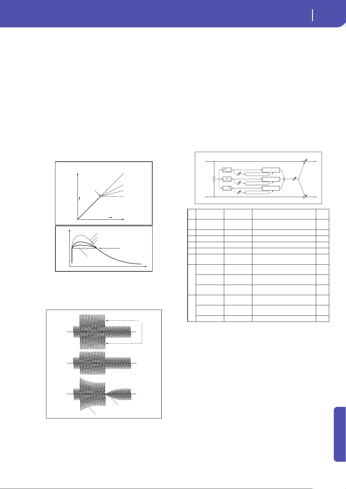
3: Multiband Limiter
This effect applies the Limiter to the low range, mid range, and
high range of the input signal. You can control dynamics for each
range to adjust the sound pressure of the low range, mid range,
and high range in a different way from the EQ.
e: Low Offset [dB]
f: Mid Offset [dB]
g: High Offset [dB]
These parameters set the gain of the trigger signal.
For example, if you do not want to apply compression to the high
range, reduce the “High Offset” value down below the “Thresh-
old” level. In this way, the high range limiter will not respond,
and compression will not be applied.
Input Level
Output Level
Threshold
Ratio=1.0 : 1
Ratio=2.0 : 1
Ratio=4.0 : 1
Ration=Inf : 1
Louder
Louder
Time
Level
Threshold
Ratio=Inf : 1
Ratio=2.0 : 1
Ratio=4.0 : 1
Dry
Ratio=1.0 : 1
Limiter - Threshold / Ratio
Threshold
Ratio=Inf : 1
Attack=1
Release=1
Ratio=Inf : 1
Attack=100
Release=100
Dry
Wet
Wet
Release
Attack
Limiter - Attack / Release
aRatio
1.0 : 1...50.0 : 1,
Inf : 1
Sets the signal compression ratio
b Threshold [dB] –40...0
Sets the level above which the
compressor is applied
c Attack 1...100 Sets the attack time
d Release 1...100 Sets the release time
e Low Offset [dB] –40...0 Gain of the low-range trigger signal
f Mid Offset [dB] –40...0 Gain of the mid-range trigger signal
g
High Offset
[dB]
–40...0 Gain of the high-range trigger signal
h
Gain Adjust
[dB]
–Inf,
–38...+24
Sets the output gain
Src Off...Tempo
Selects the modulation source for
the output gain
Amt –63...+63
Sets the modulation amount of the
output gain
i
Wet/Dry
Dry, 1:99...99:1,
Wet
Balance between the wet and dry
signal
Src Off...Tempo
Table , “Dynamic Modulation
sources,” on page 283
Amt –100...+100 Amount of modulation source
Left
Right
FX Amt
FX Amt
FX Amt = 100: Mono In - Mono Out / FX Amt = 0: Stereo In - Stereo Out
Gain Adjust
Mid Offset
Low Offset
High Offset
Envelope - Control
Envelope - Control
Envelope - Control
Low
Mid
High
Band-Pass Filters
+
Limiter
Limiter
Limiter
Loading ...
Loading ...
Loading ...