Loading ...
Loading ...
Loading ...
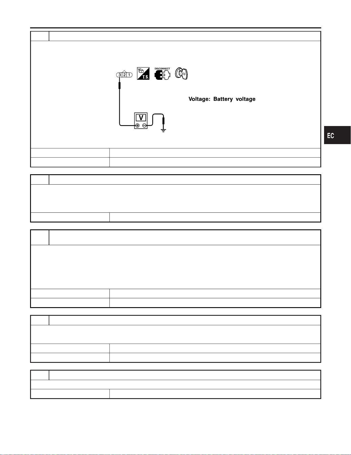
2 CHECK ELECTRONIC CONTROLLED ENGINE MOUNT POWER SUPPLY CIRCUIT
1. Turn ignition switch “OFF”.
2. Disconnect front or rear electronic controlled engine mount harness connector.
3. Check voltage between electronic controlled engine mount terminal 3 and ground with CONSULT-II or tester.
SEF899X
OK or NG
OK © GO TO 4.
NG © GO TO 3.
3 DETECT MALFUNCTIONING PART
Check the following.
I Harness connectors E15, F18
I 15A fuse
I Harness for open or short between electronic controlled engine mount and battery
© Repair harness or connectors.
4 CHECK ELECTRONIC CONTROLLED ENGINE MOUNT OUTPUT SIGNAL CIRCUIT FOR OPEN AND
SHORT
1. Disconnect ECM harness connector.
2. Check harness continuity between ECM terminal 49 and electronic controlled engine mount terminal 1, ECM terminal
50 and electronic controlled engine mount terminal 2. Refer to Wiring Diagram.
Continuity should exist.
3. Also check harness for short to ground and short to power.
OK or NG
OK © GO TO 5.
NG © Repair open circuit, short to ground or short to power in harness connectors.
5 CHECK ELECTRONIC CONTROLLED ENGINE MOUNT
Visually check front and rear electronic controlled engine mount.
OK or NG
OK © GO TO 6.
NG © Replace front or rear engine mount assembly.
6 CHECK INTERMITTENT INCIDENT
Refer to “TROUBLE DIAGNOSIS FOR INTERMITTENT INCIDENT”, EC-144.
© INSPECTION END
GI
MA
EM
LC
FE
AT
AX
SU
BR
ST
RS
BT
HA
SC
EL
IDX
ELECTRONIC CONTROLLED ENGINE MOUNT
Diagnostic Procedure (Cont’d)
EC-627
Loading ...
Loading ...
Loading ...