Loading ...
Loading ...
Loading ...
SEF327R
Component Description
NHEC0130
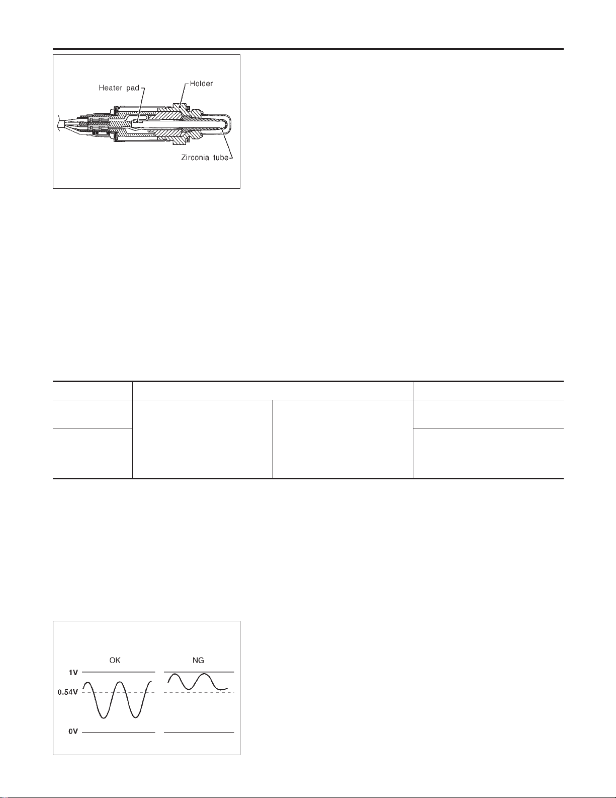
The heated oxygen sensor 2 (rear), after three way catalyst
(Manifold), monitors the oxygen level in the exhaust gas on each
bank.
Even if switching characteristics of the heated oxygen sensor 1
(front) are shifted, the air fuel ratio is controlled to stoichiometric,
by the signal from the heated oxygen sensor 2 (rear).
This sensor is made of ceramic zirconia. The zirconia generates
voltage from approximately 1V in richer conditions to 0V in leaner
conditions.
Under normal conditions the heated oxygen sensor 2 (rear) is not
used for engine control operation.
CONSULT-II Reference Value in Data Monitor
Mode
NHEC0131
Specification data are reference values.
MONITOR ITEM CONDITION SPECIFICATION
HO2S2 (B1)
HO2S2 (B2)
I Engine: After warming up
Revving engine from idle up to
2,000 rpm
0 - 0.3V +, Approx. 0.6 - 1.0V
HO2S2 MNTR
(B1)
HO2S2 MNTR
(B2)
LEAN +, RICH
SEF304U
On Board Diagnosis Logic
NHEC0133
The heated oxygen sensor 2 (rear) has a much longer switching
time between rich and lean than the heated oxygen sensor 1
(front). The oxygen storage capacity before the three way catalyst
(Manifold) causes the longer switching time. To judge the malfunc-
tions of heated oxygen sensor 2 (rear), ECM monitors whether the
minimum voltage of sensor is sufficiently low during the various
driving condition such as fuel-cut.
Malfunction is detected when the minimum voltage from the sen-
sor is not reached to the specified voltage.
DTC P0137 (BANK 1), P0157 (BANK 2) HO2S2 (REAR) (MIN. VOLTAGE
MONITORING)
Component Description
EC-246
Loading ...
Loading ...
Loading ...