Loading ...
Loading ...
Loading ...
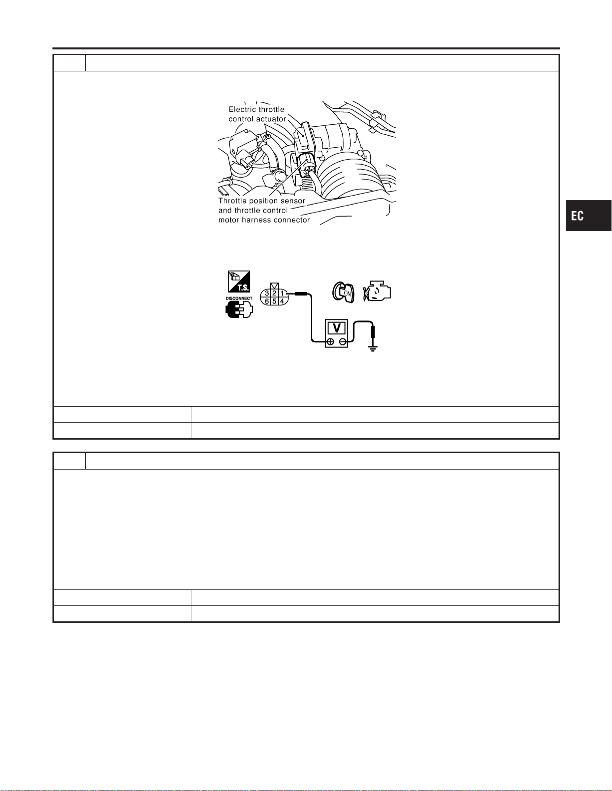
2 CHECK THROTTLE POSITION SENSOR POWER SUPPLY CIRCUIT
1. Disconnect electric throttle control actuator harness connector.
2. Turn ignition switch “ON”.
SEC054D
3. Check voltage between electric throttle control actuator terminal 1 and ground with CONSULT-II or tester.
PBIB0082E
Voltage: Approximately 5V
OK or NG
OK © GO TO 5.
NG © GO TO 3.
3 CHECK SENSOR POWER SUPPLY CIRCUITS
Check the following.
I Harness for short to power and short to ground, between the following terminals.
ECM terminal 111 and electric throttle control actuator terminal 1. Refer to “Wiring Diagram”, EC-569.
ECM terminal 111 and APP sensor terminal 2. Refer to “Wiring Diagram”, EC-313.
ECM terminal 111 and MAF sensor terminal 2. Refer to “Wiring Diagram”, EC-197.
ECM terminal 111 and EVAP control system pressure sensor terminal 1. Refer to “Wiring Diagram”, EC-392.
ECM terminal 111 and power steering pressure sensor terminal 1. Refer to “Wiring Diagram”, EC-451.
ECM terminal 111 and refrigerant pressure sensor terminal 1. Refer to “Wiring Diagram”, EC-725.
I ECM pin terminal
OK or NG
OK © GO TO 4.
NG © Repair short to ground or short to power in harness or connectors.
GI
MA
EM
LC
FE
CL
MT
AT
AX
SU
BR
ST
RS
BT
HA
SC
EL
IDX
DTC P1229 SENSOR POWER SUPPLY
Diagnostic Procedure (Cont’d)
EC-571
Loading ...
Loading ...
Loading ...