Loading ...
Loading ...
Loading ...
Specification data are reference values and are measured between each terminal and ground.
CAUTION:
Do not use ECM ground terminals when measuring input/output voltage. Doing so may result in dam-
age to the ECM’s transistor. Use a ground other than ECM terminals, such as the ground.
TERMI-
NAL
NO.
WIRE
COLOR
ITEM CONDITION DATA (DC Voltage)
58 B Sensors’ ground
[Engine is running]
I Warm-up condition
I Idle speed
Approximately 0V
64 OR
Accelerator pedal posi-
tion sensor 2 power
supply
[Ignition switch “ON”] Approximately 2.5V
70 B/P
Accelerator pedal posi-
tion sensor 2 ground
[Ignition switch “ON”] Approximately 0V
73 W
Accelerator pedal posi-
tion sensor 1
[Ignition switch “ON”]
I Accelerator pedal fully released
0.41 - 0.71V
[Ignition switch “ON”]
I Accelerator pedal fully depressed
More than 3.7V
74 W/B
Accelerator pedal posi-
tion sensor 2
[Ignition switch “ON”]
I Accelerator pedal fully released
0.08 - 0.48V
[Ignition switch “ON”]
I Accelerator pedal fully depressed
More than 1.8V
111 R Sensor’s power supply [Ignition switch “ON”] Approximately 5V
Diagnostic Procedure
NFEC1384
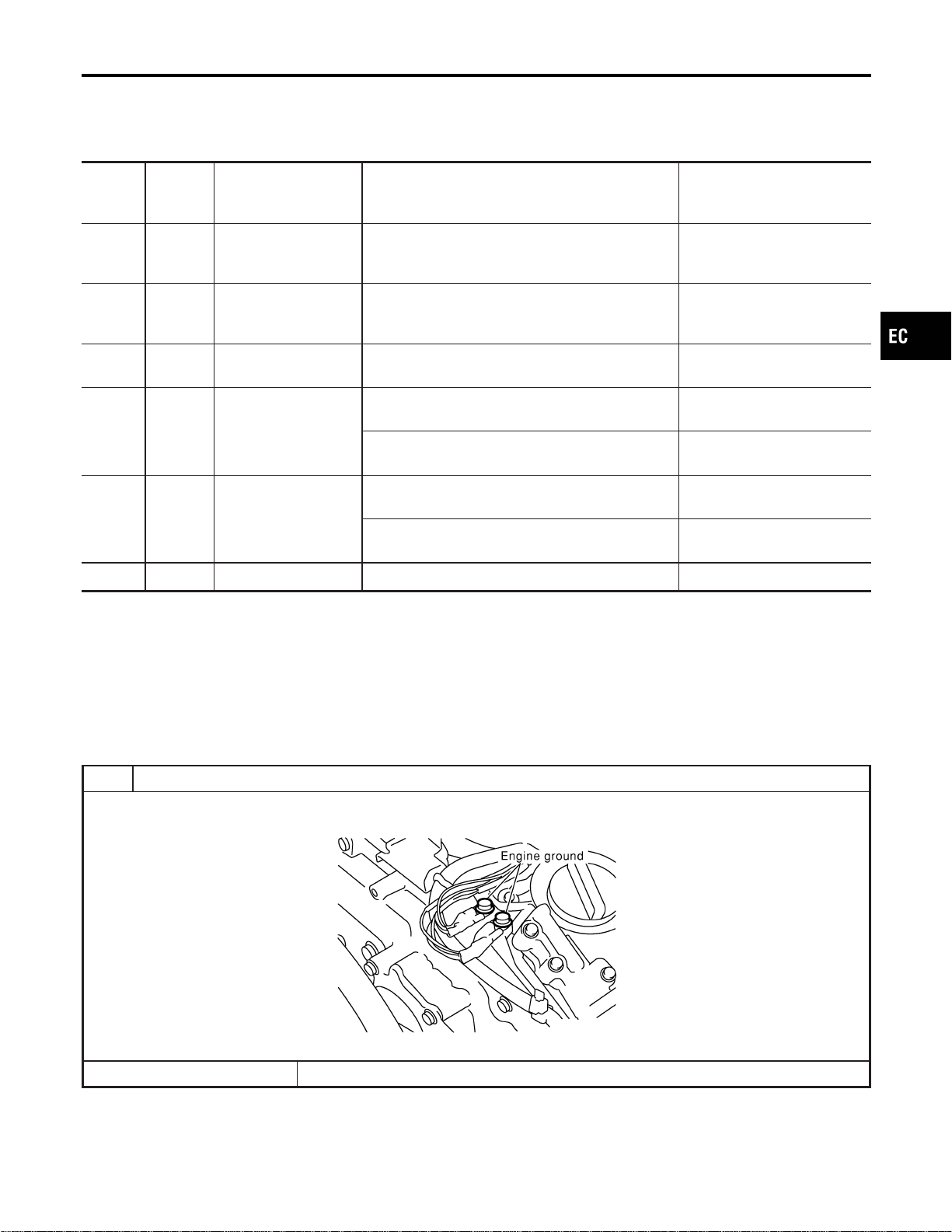
1 RETIGHTEN GROUND SCREWS
1. Turn ignition switch “OFF”.
2. Loosen and retighten engine ground screws.
SEC047D
© GO TO 2.
GI
MA
EM
LC
FE
CL
MT
AT
AX
SU
BR
ST
RS
BT
HA
SC
EL
IDX
DTC P0226 APP SENSOR
Wiring Diagram (Cont’d)
EC-307
Loading ...
Loading ...
Loading ...