ENGINE CONTROL SYSTEM
SECTION
EC
CONTENTS
TROUBLE DIAGNOSIS - INDEX ....................................9
Alphabetical Index .......................................................9
DTC No. Index...........................................................13
PRECAUTIONS .............................................................18
Supplemental Restraint System (SRS) ″AIR
BAG″ and ″SEAT BELT PRE-TENSIONER″.............18
Precautions for On Board Diagnostic (OBD)
System of Engine and A/T.........................................18
Engine Fuel & Emission Control System..................19
Precautions................................................................20
Wiring Diagrams and Trouble Diagnosis...................21
PREPARATION .............................................................22
Special Service Tools ................................................22
Commercial Service Tools.........................................22
ENGINE AND EMISSION CONTROL OVERALL
SYSTEM.........................................................................24
Engine Control Component Parts Location...............24
Circuit Diagram..........................................................28
System Diagram........................................................29
Vacuum Hose Drawing..............................................30
System Chart.............................................................31
ENGINE AND EMISSION BASIC CONTROL
SYSTEM DESCRIPTION...............................................32
Multiport Fuel Injection (MFI) System .......................32
Electronic Ignition (EI) System..................................34
Air Conditioning Cut Control......................................35
Fuel Cut Control (at no load & high engine
speed)........................................................................36
Evaporative Emission System...................................36
On Board Refueling Vapor Recovery (ORVR)..........42
Positive Crankcase Ventilation..................................51
CAN Communication.................................................52
Automatic Speed Control Device (ASCD) System....53
BASIC SERVICE PROCEDURE...................................56
Fuel Pressure Release..............................................56
Fuel Pressure Check.................................................56
Injector.......................................................................57
How to Check Idle Speed and Ignition Timing..........58
Idle Speed/Ignition Timing/Idle Mixture Ratio
Adjustment.................................................................59
Accelerator Pedal Released Position Learning.........71
Throttle Valve Closed Position Learning...................71
Idle Air Volume Learning ...........................................71
ON BOARD DIAGNOSTIC SYSTEM
DESCRIPTION...............................................................75
Introduction................................................................75
Two Trip Detection Logic...........................................75
Emission-related Diagnostic Information...................76
Malfunction Indicator Lamp (MIL)..............................92
OBD System Operation Chart...................................96
CONSULT-II.............................................................101
Generic Scan Tool (GST)........................................117
TROUBLE DIAGNOSIS - INTRODUCTION................119
Introduction..............................................................119
Work Flow................................................................121
TROUBLE DIAGNOSIS - BASIC INSPECTION.........123
Basic Inspection.......................................................123
TROUBLE DIAGNOSIS - GENERAL
DESCRIPTION.............................................................128
DTC Inspection Priority Chart..................................128
Fail-safe Chart.........................................................129
Symptom Matrix Chart.............................................131
CONSULT-II Reference Value in Data Monitor
Mode........................................................................135
Major Sensor Reference Graph in Data Monitor
Mode........................................................................138
ECM Terminals and Reference Value .....................141
TROUBLE DIAGNOSIS - SPECIFICATION VALUE ..152
Description...............................................................152
Testing Condition.....................................................152
Inspection Procedure...............................................152
Diagnostic Procedure ..............................................153
TROUBLE DIAGNOSIS FOR INTERMITTENT
INCIDENT.....................................................................156
Description...............................................................156
Diagnostic Procedure ..............................................156
TROUBLE DIAGNOSIS FOR POWER SUPPLY........157
GI
MA
EM
LC
FE
CL
MT
AT
AX
SU
BR
ST
RS
BT
HA
SC
EL
IDX

Main Power Supply and Ground Circuit..................157
DTC U1000, U1001 CAN COMMUNICATION LINE...164
Description...............................................................164
On Board Diagnosis Logic.......................................164
DTC Confirmation Procedure..................................164
Wiring Diagram........................................................165
Diagnostic Procedure ..............................................166
DTC P0011, P0021 IVT CONTROL ............................167
Description...............................................................167
CONSULT-II Reference Value in Data Monitor
Mode........................................................................167
On Board Diagnosis Logic.......................................168
DTC Confirmation Procedure..................................168
Wiring Diagram........................................................169
Diagnostic Procedure ..............................................172
Component Inspection.............................................174
DTC P0031, P0032, P0051, P0052 HO2S1
HEATER.......................................................................175
Description...............................................................175
CONSULT-II Reference Value in Data Monitor
Mode........................................................................175
On Board Diagnosis Logic.......................................175
DTC Confirmation Procedure..................................176
Wiring Diagram........................................................177
Diagnostic Procedure ..............................................179
DTC P0037, P0038, P0057, P0058 HO2S2
HEATER.......................................................................181
Description...............................................................181
CONSULT-II Reference Value in Data Monitor
Mode........................................................................181
On Board Diagnosis Logic.......................................181
DTC Confirmation Procedure..................................182
Wiring Diagram........................................................183
Diagnostic Procedure ..............................................185
DTC P0101 MAF SENSOR.........................................188
Component Description...........................................188
CONSULT-II Reference Value in Data Monitor
Mode........................................................................188
On Board Diagnosis Logic.......................................188
DTC Confirmation Procedure..................................189
Overall Function Check...........................................190
Wiring Diagram........................................................191
Diagnostic Procedure ..............................................192
DTC P0102, P0103 MAF SENSOR.............................195
Component Description...........................................195
CONSULT-II Reference Value in Data Monitor
Mode........................................................................195
On Board Diagnosis Logic.......................................195
DTC Confirmation Procedure..................................196
Wiring Diagram........................................................197
Diagnostic Procedure ..............................................198
DTC P0107, P0108 ABSOLUTE PRESSURE
SENSOR ......................................................................201
Component Description...........................................201
On Board Diagnosis Logic.......................................201
DTC Confirmation Procedure..................................201
Diagnostic Procedure ..............................................202
DTC P0112, P0113 IAT SENSOR...............................203
Component Description...........................................203
On Board Diagnosis Logic.......................................203
DTC Confirmation Procedure..................................203
Wiring Diagram........................................................204
Diagnostic Procedure ..............................................205
DTC P0117, P0118 ECT SENSOR..............................207
Component Description...........................................207
On Board Diagnosis Logic.......................................207
DTC Confirmation Procedure..................................208
Wiring Diagram........................................................209
Diagnostic Procedure ..............................................210
DTC P0121, P0122, P0123 .........................................212
Description...............................................................212
DTC P0125 ECT SENSOR..........................................213
Description...............................................................213
On Board Diagnosis Logic.......................................213
DTC Confirmation Procedure..................................214
Diagnostic Procedure ..............................................214
DTC P0127 IAT SENSOR ...........................................216
Component Description...........................................216
On Board Diagnosis Logic.......................................216
DTC Confirmation Procedure..................................216
Diagnostic Procedure ..............................................217
DTC P0128 THERMOSTAT FUNCTION.....................218
On Board Diagnosis Logic.......................................218
DTC Confirmation Procedure..................................218
Diagnostic Procedure ..............................................219
DTC P0132, P0152 HO2S1.........................................220
Component Description...........................................220
CONSULT-II Reference Value in Data Monitor
Mode........................................................................220
On Board Diagnosis Logic.......................................220
DTC Confirmation Procedure..................................221
Wiring Diagram........................................................222
Diagnostic Procedure ..............................................224
DTC P0133, P0153 HO2S1.........................................228
Component Description...........................................228
CONSULT-II Reference Value in Data Monitor
Mode........................................................................228
On Board Diagnosis Logic.......................................228
DTC Confirmation Procedure..................................229
Overall Function Check...........................................230
Wiring Diagram........................................................231
Diagnostic Procedure ..............................................233
DTC P0134, P0154 HO2S1.........................................240
CONTENTS (Cont’d)
EC-2

Component Description...........................................240
CONSULT-II Reference Value in Data Monitor
Mode........................................................................240
On Board Diagnosis Logic.......................................240
DTC Confirmation Procedure..................................241
Overall Function Check...........................................242
Wiring Diagram........................................................243
Diagnostic Procedure ..............................................245
DTC P0138, P0158 HO2S2.........................................249
Component Description...........................................249
CONSULT-II Reference Value in Data Monitor
Mode........................................................................249
On Board Diagnosis Logic.......................................249
DTC Confirmation Procedure..................................250
Overall Function Check...........................................250
Wiring Diagram........................................................251
Diagnostic Procedure ..............................................253
DTC P0139, P0159 HO2S2.........................................257
Component Description...........................................257
CONSULT-II Reference Value in Data Monitor
Mode........................................................................257
On Board Diagnosis Logic.......................................257
DTC Confirmation Procedure..................................258
Overall Function Check...........................................258
Wiring Diagram........................................................260
Diagnostic Procedure ..............................................262
DTC P0171, P0174 FUEL INJECTION SYSTEM
FUNCTION...................................................................267
On Board Diagnosis Logic.......................................267
DTC Confirmation Procedure..................................267
Wiring Diagram........................................................269
Diagnostic Procedure ..............................................271
DTC P0172, P0175 FUEL INJECTION SYSTEM
FUNCTION...................................................................275
On Board Diagnosis Logic.......................................275
DTC Confirmation Procedure..................................275
Wiring Diagram........................................................277
Diagnostic Procedure ..............................................279
DTC P0181 FTT SENSOR ..........................................282
Component Description...........................................282
On Board Diagnosis Logic.......................................282
DTC Confirmation Procedure..................................282
Diagnostic Procedure ..............................................283
DTC P0182, P0183 FTT SENSOR..............................285
Component Description...........................................285
On Board Diagnosis Logic.......................................285
DTC Confirmation Procedure..................................285
Wiring Diagram........................................................287
Diagnostic Procedure ..............................................288
DTC P0221 TP SENSOR ............................................290
Component Description...........................................290
CONSULT-II Reference Value in Data Monitor
Mode........................................................................290
On Board Diagnosis Logic.......................................290
DTC Confirmation Procedure..................................291
Wiring Diagram........................................................292
Diagnostic Procedure ..............................................293
Component Inspection.............................................295
DTC P0222, P0223 TP SENSOR................................297
Component Description...........................................297
CONSULT-II Reference Value in Data Monitor
Mode........................................................................297
On Board Diagnosis Logic.......................................297
DTC Confirmation Procedure..................................298
Wiring Diagram........................................................299
Diagnostic Procedure ..............................................300
Component Inspection.............................................302
DTC P0226 APP SENSOR..........................................304
Component Description...........................................304
CONSULT-II Reference Value in Data Monitor
Mode........................................................................304
On Board Diagnosis Logic.......................................304
DTC Confirmation Procedure..................................305
Wiring Diagram........................................................306
Diagnostic Procedure ..............................................307
Component Inspection.............................................309
DTC P0227, P0228 APP SENSOR.............................311
Component Description...........................................311
CONSULT-II Reference Value in Data Monitor
Mode........................................................................311
On Board Diagnosis Logic.......................................311
DTC Confirmation Procedure..................................312
Wiring Diagram........................................................313
Diagnostic Procedure ..............................................314
Component Inspection.............................................316
DTC P0300 - P0306 MULTIPLE CYLINDER
MISFIRE, NO.1-6CYLINDER MISFIRE..................317
On Board Diagnosis Logic.......................................317
DTC Confirmation Procedure..................................318
Diagnostic Procedure ..............................................318
DTC P0327, P0328 KS................................................325
Component Description...........................................325
On Board Diagnosis Logic.......................................325
DTC Confirmation Procedure..................................325
Wiring Diagram........................................................326
Diagnostic Procedure ..............................................327
DTC P0335 CKP SENSOR (POS)..............................330
Component Description...........................................330
CONSULT-II Reference Value in Data Monitor
Mode........................................................................330
On Board Diagnosis Logic.......................................330
DTC Confirmation Procedure..................................331
Wiring Diagram........................................................332
GI
MA
EM
LC
FE
CL
MT
AT
AX
SU
BR
ST
RS
BT
HA
SC
EL
IDX
CONTENTS (Cont’d)
EC-3

Diagnostic Procedure ..............................................333
Component Inspection.............................................336
DTC P0340, P0345 CMP SENSOR (PHASE) ............337
Component Description...........................................337
On Board Diagnosis Logic.......................................337
DTC Confirmation Procedure..................................337
Wiring Diagram........................................................339
Diagnostic Procedure ..............................................342
Component Inspection.............................................345
DTC P0420, P0430 THREE WAY CATALYST
FUNCTION...................................................................346
On Board Diagnosis Logic.......................................346
DTC Confirmation Procedure..................................346
Overall Function Check...........................................347
Diagnostic Procedure ..............................................347
DTC P0441 EVAP CONTROL SYSTEM.....................351
System Description..................................................351
On Board Diagnosis Logic.......................................351
DTC Confirmation Procedure..................................352
Overall Function Check...........................................352
Diagnostic Procedure ..............................................354
DTC P0442 EVAP CONTROL SYSTEM.....................361
On Board Diagnosis Logic.......................................361
DTC Confirmation Procedure..................................362
Diagnostic Procedure ..............................................363
DTC P0444, P0445 EVAP CANISTER PURGE
VOLUME CONTROL SOLENOID VALVE ..................376
Description...............................................................376
CONSULT-II Reference Value in Data Monitor
Mode........................................................................376
On Board Diagnosis Logic.......................................377
DTC Confirmation Procedure..................................377
Wiring Diagram........................................................378
Diagnostic Procedure ..............................................380
DTC P0447 EVAP CANISTER VENT CONTROL
VALVE..........................................................................383
Component Description...........................................383
CONSULT-II Reference Value in Data Monitor
Mode........................................................................383
On Board Diagnosis Logic.......................................383
DTC Confirmation Procedure..................................383
Wiring Diagram........................................................385
Diagnostic Procedure ..............................................386
DTC P0452 EVAP SYSTEM PRESSURE SENSOR ..390
Component Description...........................................390
CONSULT-II Reference Value in Data Monitor
Mode........................................................................390
On Board Diagnosis Logic.......................................390
DTC Confirmation Procedure..................................390
Wiring Diagram........................................................392
Diagnostic Procedure ..............................................393
DTC P0453 EVAP SYSTEM PRESSURE SENSOR ..396
Component Description...........................................396
CONSULT-II Reference Value in Data Monitor
Mode........................................................................396
On Board Diagnosis Logic.......................................396
DTC Confirmation Procedure..................................397
Wiring Diagram........................................................398
Diagnostic Procedure ..............................................399
DTC P0455 EVAP CONTROL SYSTEM (GROSS
LEAK)...........................................................................405
On Board Diagnosis Logic.......................................405
Possible Cause........................................................405
DTC Confirmation Procedure..................................406
Diagnostic Procedure ..............................................407
DTC P0456 EVAP CONTROL SYSTEM.....................417
On Board Diagnosis Logic.......................................417
DTC Confirmation Procedure..................................418
Overall Function Check...........................................419
Diagnostic Procedure ..............................................419
DTC P0460 FUEL LEVEL SENSOR...........................432
Component Description...........................................432
On Board Diagnostic Logic......................................432
DTC Confirmation Procedure..................................432
Wiring Diagram........................................................433
Diagnostic Procedure ..............................................434
DTC P0461 FUEL LEVEL SENSOR...........................436
Component Description...........................................436
On Board Diagnostic Logic......................................436
Overall Function Check...........................................436
DTC P0462, P0463 FUEL LEVEL SENSOR..............438
Component Description...........................................438
On Board Diagnostic Logic......................................438
DTC Confirmation Procedure..................................438
Wiring Diagram........................................................439
Diagnostic Procedure ..............................................440
DTC P0500 VSS..........................................................442
Component Description...........................................442
On Board Diagnosis Logic.......................................442
DTC Confirmation Procedure..................................442
Overall Function Check...........................................443
Wiring Diagram........................................................444
Diagnostic Procedure ..............................................445
DTC P0506 ISC SYSTEM ...........................................446
Description...............................................................446
On Board Diagnosis Logic.......................................446
DTC Confirmation Procedure..................................446
Diagnostic Procedure ..............................................447
DTC P0507 ISC SYSTEM ...........................................448
Description...............................................................448
On Board Diagnosis Logic.......................................448
DTC Confirmation Procedure..................................448
Diagnostic Procedure ..............................................449
DTC P0550 PSP SENSOR..........................................450
CONTENTS (Cont’d)
EC-4

Component Description...........................................450
CONSULT-II Reference Value in Data Monitor
Mode........................................................................450
On Board Diagnosis Logic.......................................450
DTC Confirmation Procedure..................................450
Wiring Diagram........................................................451
Diagnostic Procedure ..............................................452
Component Inspection.............................................454
DTC P0605 ECM .........................................................455
Component Description...........................................455
On Board Diagnosis Logic.......................................455
DTC Confirmation Procedure..................................455
Diagnostic Procedure ..............................................456
DTC P0650 MIL (CIRCUIT).........................................457
Component Description...........................................457
On Board Diagnosis Logic.......................................457
DTC Confirmation Procedure..................................457
Wiring Diagram........................................................458
Diagnostic Procedure ..............................................459
DTC P1065 ECM POWER SUPPLY (BACK UP).......461
Component Description...........................................461
On Board Diagnosis Logic.......................................461
DTC Confirmation Procedure..................................461
Wiring Diagram........................................................462
Diagnostic Procedure ..............................................463
DTC P1102 MAF SENSOR .........................................465
Component Description...........................................465
CONSULT-II Reference Value in Data Monitor
Mode........................................................................465
On Board Diagnosis Logic.......................................465
DTC Confirmation Procedure..................................465
Wiring Diagram........................................................467
Diagnostic Procedure ..............................................468
DTC P1121 ELECTRIC THROTTLE CONTROL
ACTUATOR .................................................................471
Component Description...........................................471
On Board Diagnosis Logic.......................................471
DTC Confirmation Procedure..................................471
Diagnostic Procedure ..............................................472
DTC P1122 ELECTRIC THROTTLE CONTROL
FUNCTION...................................................................473
Description...............................................................473
On Board Diagnosis Logic.......................................473
DTC Confirmation Procedure..................................473
Wiring Diagram........................................................475
Diagnostic Procedure ..............................................476
Component Inspection.............................................480
DTC P1124, P1126 THROTTLE CONTROL
MOTOR RELAY...........................................................481
Component Description...........................................481
CONSULT-II Reference Value in Data Monitor
Mode........................................................................481
On Board Diagnosis Logic.......................................481
DTC Confirmation Procedure..................................481
Wiring Diagram........................................................483
Diagnostic Procedure ..............................................484
Component Inspection.............................................486
DTC P1128 THROTTLE CONTROL MOTOR.............487
Component Description...........................................487
On Board Diagnosis Logic.......................................487
DTC Confirmation Procedure..................................487
Wiring Diagram........................................................488
Diagnostic Procedure ..............................................489
Component Inspection.............................................491
DTC P1143, P1163 HO2S1 .........................................492
Component Description...........................................492
CONSULT-II Reference Value in Data Monitor
Mode........................................................................492
On Board Diagnosis Logic.......................................492
DTC Confirmation Procedure..................................493
Overall Function Check...........................................494
Diagnostic Procedure ..............................................494
DTC P1144, P1164 HO2S1 .........................................499
Component Description...........................................499
CONSULT-II Reference Value in Data Monitor
Mode........................................................................499
On Board Diagnosis Logic.......................................499
DTC Confirmation Procedure..................................500
Overall Function Check...........................................501
Diagnostic Procedure ..............................................501
DTC P1146, P1166 HO2S2 .........................................506
Component Description...........................................506
CONSULT-II Reference Value in Data Monitor
Mode........................................................................506
On Board Diagnosis Logic.......................................506
DTC Confirmation Procedure..................................507
Overall Function Check...........................................507
Wiring Diagram........................................................509
Diagnostic Procedure ..............................................511
DTC P1147, P1167 HO2S2 .........................................516
Component Description...........................................516
CONSULT-II Reference Value in Data Monitor
Mode........................................................................516
On Board Diagnosis Logic.......................................516
DTC Confirmation Procedure..................................517
Overall Function Check...........................................517
Wiring Diagram........................................................519
Diagnostic Procedure ..............................................521
DTC P1148, P1168 CLOSED LOOP CONTROL........526
On Board Diagnosis Logic.......................................526
DTC Confirmation Procedure..................................526
Overall Function Check...........................................527
Diagnostic Procedure ..............................................527
DTC P1211 ABS/TCS CONTROL UNIT .....................528
GI
MA
EM
LC
FE
CL
MT
AT
AX
SU
BR
ST
RS
BT
HA
SC
EL
IDX
CONTENTS (Cont’d)
EC-5

Description...............................................................528
On Board Diagnosis Logic.......................................528
DTC Confirmation Procedure..................................528
Diagnostic Procedure ..............................................529
DTC P1212 ABS/TCS COMMUNICATION LINE........530
Description...............................................................530
On Board Diagnosis Logic.......................................530
DTC Confirmation Procedure..................................530
Diagnostic Procedure ..............................................531
DTC P1217 ENGINE OVER TEMPERATURE............532
System Description..................................................532
CONSULT-II Reference Value in Data Monitor
Mode........................................................................532
On Board Diagnosis Logic.......................................533
Overall Function Check...........................................534
Wiring Diagram........................................................536
Diagnostic Procedure ..............................................538
Main 12 Causes of Overheating..............................549
DTC P1223, P1224 TP SENSOR................................550
Component Description...........................................550
CONSULT-II Reference Value in Data Monitor
Mode........................................................................550
On Board Diagnosis Logic.......................................550
DTC Confirmation Procedure..................................551
Wiring Diagram........................................................552
Diagnostic Procedure ..............................................553
Component Inspection.............................................555
DTC P1225 TP SENSOR ............................................557
Component Description...........................................557
On Board Diagnosis Logic.......................................557
DTC Confirmation Procedure..................................557
Diagnostic Procedure ..............................................558
DTC P1226 TP SENSOR ............................................559
Component Description...........................................559
On Board Diagnosis Logic.......................................559
DTC Confirmation Procedure..................................559
Diagnostic Procedure ..............................................560
DTC P1227, P1228 APP SENSOR.............................561
Component Description...........................................561
CONSULT-II Reference Value in Data Monitor
Mode........................................................................561
On Board Diagnosis Logic.......................................561
DTC Confirmation Procedure..................................562
Wiring Diagram........................................................563
Diagnostic Procedure ..............................................564
Component Inspection.............................................566
DTC P1229 SENSOR POWER SUPPLY....................567
On Board Diagnosis Logic.......................................567
DTC Confirmation Procedure..................................567
Wiring Diagram........................................................569
Diagnostic Procedure ..............................................570
DTC P1444 EVAP CANISTER PURGE VOLUME
CONTROL SOLENOID VALVE...................................573
Description...............................................................573
CONSULT-II Reference Value in Data Monitor
Mode........................................................................573
On Board Diagnosis Logic.......................................574
DTC Confirmation Procedure..................................574
Wiring Diagram........................................................576
Diagnostic Procedure ..............................................578
DTC P1446 EVAP CANISTER VENT CONTROL
VALVE..........................................................................586
Component Description...........................................586
CONSULT-II Reference Value in Data Monitor
Mode........................................................................586
On Board Diagnosis Logic.......................................586
DTC Confirmation Procedure..................................586
Wiring Diagram........................................................588
Diagnostic Procedure ..............................................589
DTC P1448 EVAP CANISTER VENT CONTROL
VALVE..........................................................................594
Component Description...........................................594
CONSULT-II Reference Value in Data Monitor
Mode........................................................................594
On Board Diagnosis Logic.......................................594
DTC Confirmation Procedure..................................594
Overall Function Check...........................................596
Wiring Diagram........................................................597
Diagnostic Procedure ..............................................598
DTC P1456 EVAP CONTROL SYSTEM.....................603
On Board Diagnosis Logic.......................................603
DTC Confirmation Procedure..................................604
Overall Function Check...........................................605
Diagnostic Procedure ..............................................606
DTC P1464 FUEL LEVEL SENSOR...........................619
Component Description...........................................619
On Board Diagnostic Logic......................................619
DTC Confirmation Procedure..................................619
Wiring Diagram........................................................620
Diagnostic Procedure ..............................................621
DTC P1490 VACUUM CUT VALVE BYPASS
VALVE..........................................................................622
Description...............................................................622
CONSULT-II Reference Value in Data Monitor
Mode........................................................................622
On Board Diagnosis Logic.......................................622
DTC Confirmation Procedure..................................623
Wiring Diagram........................................................624
Diagnostic Procedure ..............................................625
DTC P1491 VACUUM CUT VALVE BYPASS
VALVE..........................................................................628
Description...............................................................628
CONTENTS (Cont’d)
EC-6

CONSULT-II Reference Value in Data Monitor
Mode........................................................................628
On Board Diagnosis Logic.......................................629
DTC Confirmation Procedure..................................629
Overall Function Check...........................................630
Wiring Diagram........................................................631
Diagnostic Procedure ..............................................632
DTC P1564 ASCD STEERING SWITCH ....................640
Component Description...........................................640
CONSULT-II Reference Value in Data Monitor
Mode........................................................................640
On Board Diagnosis Procedure...............................640
DTC Confirmation Procedure..................................640
Wiring Diagram........................................................642
Diagnostic Procedure ..............................................644
Component Inspection.............................................646
DTC P1572 ASCD BRAKE SWITCH..........................647
Component Description...........................................647
CONSULT-II Reference Value in Data Monitor
Mode........................................................................647
On Board Diagnosis Procedure...............................647
DTC Confirmation Procedure..................................648
Wiring Diagram........................................................649
Diagnostic Procedure ..............................................651
Component Inspection.............................................661
DTC P1574 ASCD VEHICLE SPEED SENSOR.........662
Component Description...........................................662
On Board Diagnosis Procedure...............................662
DTC Confirmation Procedure..................................662
Wiring Diagram........................................................664
Diagnostic Procedure ..............................................665
DTC P1706 PNP SWITCH...........................................667
Component Description...........................................667
CONSULT-II Reference Value in Data Monitor
Mode........................................................................667
On Board Diagnosis Logic.......................................667
DTC Confirmation Procedure..................................667
Overall Function Check...........................................668
Wiring Diagram........................................................669
Diagnostic Procedure ..............................................670
DTC P1800 VIAS CONTROL SOLENOID VALVE.....673
Component Description...........................................673
CONSULT-II Reference Value in Data Monitor
Mode........................................................................673
On Board Diagnosis Logic.......................................673
DTC Confirmation Procedure..................................673
Wiring Diagram........................................................675
Diagnostic Procedure ..............................................676
DTC P1805 BRAKE SWITCH.....................................678
Description...............................................................678
CONSULT-II Reference Value in Data Monitor
Mode........................................................................678
On Board Diagnosis Logic.......................................678
DTC Confirmation Procedure..................................678
Wiring Diagram........................................................679
Diagnostic Procedure ..............................................680
Component Inspection.............................................683
VARIABLE INDUCTION AIR CONTROL SYSTEM
(VIAS)...........................................................................684
Description...............................................................684
Wiring Diagram........................................................686
Diagnostic Procedure ..............................................687
IGNITION SIGNAL.......................................................692
Component Description...........................................692
Wiring Diagram........................................................693
Diagnostic Procedure ..............................................696
INJECTOR ...................................................................703
Component Description...........................................703
CONSULT-II Reference Value in Data Monitor
Mode........................................................................703
Wiring Diagram........................................................704
Diagnostic Procedure ..............................................705
START SIGNAL...........................................................709
CONSULT-II Reference Value in Data Monitor
Mode........................................................................709
Wiring Diagram........................................................710
Diagnostic Procedure ..............................................711
FUEL PUMP.................................................................713
System Description..................................................713
Component Description...........................................713
CONSULT-II Reference Value in Data Monitor
Mode........................................................................713
Wiring Diagram........................................................714
Diagnostic Procedure ..............................................715
ELECTRONIC CONTROLLED ENGINE MOUNT.......720
System Description..................................................720
CONSULT-II Reference Value in Data Monitor
Mode........................................................................720
Wiring Diagram........................................................721
Diagnostic Procedure ..............................................722
REFRIGERANT PRESSURE SENSOR......................724
Description...............................................................724
Wiring Diagram........................................................725
Diagnostic Procedure ..............................................726
ASCD BRAKE SWITCH..............................................728
Component Description...........................................728
CONSULT-II Reference Value in Data Monitor
Mode........................................................................728
Wiring Diagram........................................................729
Diagnostic Procedure ..............................................731
ASCD INDICATOR LAMP...........................................741
Component Description...........................................741
CONSULT-II Reference Value in Data Monitor
Mode........................................................................741
GI
MA
EM
LC
FE
CL
MT
AT
AX
SU
BR
ST
RS
BT
HA
SC
EL
IDX
CONTENTS (Cont’d)
EC-7

Wiring Diagram........................................................742
Diagnostic Procedure ..............................................743
ELECTRICAL LOAD SIGNAL.....................................744
Wiring Diagram........................................................744
Diagnostic Procedure ..............................................745
DATA LINK CONNECTORS.......................................748
Wiring Diagram........................................................748
SERVICE DATA AND SPECIFICATIONS (SDS).......749
Fuel Pressure Regulator..........................................749
Idle Speed and Ignition Timing................................749
Mass Air Flow Sensor..............................................749
Engine Coolant Temperature Sensor......................749
Heated Oxygen Sensor 1 Heater............................749
Fuel Pump ...............................................................749
Injector.....................................................................749
Calculated Load Value.............................................749
Intake Air Temperature Sensor................................749
Heated Oxygen Sensor 2 Heater............................750
Fuel Tank Temperature Sensor ...............................750
Throttle Control Motor..............................................750
Crankshaft Position Sensor (POS)..........................750
Camshaft Position Sensor (PHASE).......................750
CONTENTS (Cont’d)
EC-8
Alphabetical Index
NFEC0001
NOTE:
If DTC U1000 or U1001 is displayed with other DTC, first perform the trouble diagnosis for DTC U1000,
U1001. Refer to EC-164.
Items (CONSULT-II screen terms)
DTC*1
Reference page
CONSULT-II
GST*2
ECM*3
Unable to access ECM — EC-129
A/T 1ST GR FNCTN P0731 0731 AT-132
A/T 2ND GR FNCTN P0732 0732 AT-138
A/T 3RD GR FNCTN P0733 0733 AT-144
A/T 4TH GR FNCTN P0734 0734 AT-158
A/T TCC S/V FNCTN P0744 0744 AT-158
ABSL PRES SEN/CIRC P0107 0107 EC-201
ABSL PRES SEN/CIRC P0108 0108 EC-201
APP SEN 1/CIRC*5 P0227 0227 EC-311
APP SEN 1/CIRC*5 P0228 0228 EC-311
APP SEN 2/CIRC*5 P1227 1227 EC-561
APP SEN 2/CIRC*5 P1228 1228 EC-561
APP SENSOR*5 P0226 0226 EC-304
APP SEN/CIRCUIT*5 P0121 0121 EC-212
ASCD BRAKE SW P1572 1572 EC-647
ASCD SW P1564 1564 EC-640
ASCD VHL SPD SEN P1574 1574 EC-662
ATF TEMP SEN/CIRC P0710 0710 AT-110
BRAKE SW/CIRCUIT P1805 1805 EC-678
CAN COMM CIRCUIT U1000 1000*6 EC-164
CAN COMM CIRCUIT U1001 1001*6 EC-164
CKP SEN/CIRCUIT P0335 0335 EC-330
CLOSED LOOP-B1 P1148 1148 EC-526
CLOSED LOOP-B2 P1168 1168 EC-526
CMP SEN/CIRC-B1 P0340 0340 EC-337
CMP SEN/CIRC-B2 P0345 0345 EC-337
CTP LEARNING P1225 1225 EC-557
CTP LEARNING P1226 1226 EC-559
CYL 1 MISFIRE P0301 0301 EC-317
CYL 2 MISFIRE P0302 0302 EC-317
CYL 3 MISFIRE P0303 0303 EC-317
CYL 4 MISFIRE P0304 0304 EC-317
CYL 5 MISFIRE P0305 0305 EC-317
GI
MA
EM
LC
FE
CL
MT
AT
AX
SU
BR
ST
RS
BT
HA
SC
EL
IDX
TROUBLE DIAGNOSIS — INDEX
Alphabetical Index
EC-9

Items (CONSULT-II screen terms)
DTC*1
Reference page
CONSULT-II
GST*2
ECM*3
CYL 6 MISFIRE P0306 0306 EC-317
ECM P0605 0605 EC-455
ECM BACK UP/CIRCUIT P1065 1065 EC-461
ECT SEN/CIRC*5 P0117 0117 EC-207
ECT SEN/CIRC*5 P0118 0118 EC-207
ECT SENSOR P0125 0125 EC-213
ENG OVER TEMP P1217 1217 EC-532
ENGINE SPEED SIG P0725 0725 AT-121
ETC MOT P1128 1128 EC-487
ETC MOT PWR P1124 1124 EC-481
ETC MOT PWR*5 P1126 1126 EC-481
ETC ACTR*5 P1121 1121 EC-471
ETC FUNCTION/CIRC*5 P1122 1122 EC-473
EVAP GROSS LEAK P0455 0455 EC-405
EVAP VERY SML LEAK P0456 0456 EC-417
EVAP VERY SML LEAK P1456 1456 EC-603
EVAP PURG FLOW/MON P0441 0441 EC-351
EVAP SMALL LEAK P0442 0442 EC-361
EVAP SYS PRES SEN P0452 0452 EC-390
EVAP SYS PRES SEN P0453 0453 EC-396
FTT SEN/CIRCUIT P0182 0182 EC-285
FTT SEN/CIRCUIT P0183 0183 EC-285
FTT SENSOR P0181 0181 EC-282
FUEL LEV SEN SLOSH P0460 0460 EC-432
FUEL LEVEL SENSOR P0461 0461 EC-436
FUEL LEVL SEN/CIRC P0462 0462 EC-438
FUEL LEVL SEN/CIRC P0463 0463 EC-438
FUEL LEVL SEN/CIRC P1464 1464 EC-619
FUEL SYS-LEAN-B1 P0171 0171 EC-267
FUEL SYS-LEAN-B2 P0174 0174 EC-267
FUEL SYS-RICH-B1 P0172 0172 EC-275
FUEL SYS-RICH-B2 P0175 0175 EC-275
HO2S1 (B1) P0132 0132 EC-220
HO2S1 (B1) P0133 0133 EC-228
HO2S1 (B1) P0134 0134 EC-240
HO2S1 (B1) P1143 1143 EC-492
TROUBLE DIAGNOSIS — INDEX
Alphabetical Index (Cont’d)
EC-10
Items (CONSULT-II screen terms)
DTC*1
Reference page
CONSULT-II
GST*2
ECM*3
HO2S1 (B1) P1144 1144 EC-499
HO2S1 (B2) P0152 0152 EC-220
HO2S1 (B2) P0153 0153 EC-228
HO2S1 (B2) P0154 0154 EC-240
HO2S1 (B2) P1163 1163 EC-492
HO2S1 (B2) P1164 1164 EC-499
HO2S1 HTR (B1) P0031 0031 EC-175
HO2S1 HTR (B1) P0032 0032 EC-175
HO2S1 HTR (B2) P0051 0051 EC-175
HO2S1 HTR (B2) P0052 0052 EC-175
HO2S2 (B1) P0138 0138 EC-249
HO2S2 (B1) P0139 0139 EC-257
HO2S2 (B1) P1146 1146 EC-506
HO2S2 (B1) P1147 1147 EC-516
HO2S2 (B2) P0158 0158 EC-249
HO2S2 (B2) P0159 0159 EC-257
HO2S2 (B2) P1166 1166 EC-506
HO2S2 (B2) P1167 1167 EC-516
HO2S2 HTR (B1) P0037 0037 EC-181
HO2S2 HTR (B1) P0038 0038 EC-181
HO2S2 HTR (B2) P0057 0057 EC-181
HO2S2 HTR (B2) P0058 0058 EC-181
IAT SEN/CIRCUIT P0112 0112 EC-203
IAT SEN/CIRCUIT P0113 0113 EC-203
IAT SENSOR P0127 0127 EC-216
INT/V TIM CONT-B1 P0011 0011 EC-167
INT/V TIM CONT-B2 P0021 0021 EC-167
ISC SYSTEM P0506 0506 EC-446
ISC SYSTEM P0507 0507 EC-448
KNOCK SEN/CIRC-B1 P0327 0327 EC-325
KNOCK SEN/CIRC-B1 P0328 0328 EC-325
L/PRESS SOL/CIRC P0745 0745 AT-168
MAF SEN/CIRCUIT P0101 0101 EC-188
MAF SEN/CIRCUIT*5 P0102 0102 EC-195
MAF SEN/CIRCUIT*5 P0103 0103 EC-195
MAF SENSOR*5 P1102 1102 EC-465
GI
MA
EM
LC
FE
CL
MT
AT
AX
SU
BR
ST
RS
BT
HA
SC
EL
IDX
TROUBLE DIAGNOSIS — INDEX
Alphabetical Index (Cont’d)
EC-11

Items (CONSULT-II screen terms)
DTC*1
Reference page
CONSULT-II
GST*2
ECM*3
MIL/CIRC P0650 0650 EC-457
MULTI CYL MISFIRE P0300 0300 EC-317
NATS MALFUNCTION P1610-P1615 1610-1615 EL-356
NO DTC IS DETECTED.
FURTHER TESTING
MAY BE REQUIRED.
No DTC Flashing*4 EC-93
NO DTC IS DETECTED.
FURTHER TESTING
MAY BE REQUIRED.
P0000 0000 —
O/R CLTCH SOL/CIRC P1760 1760 AT-191
P-N POS SW/CIRCUIT P1706 1706 EC-667
PNP SW/CIRC P0705 0705 AT-104
PURG VOLUME CONT/V P0444 0444 EC-376
PURG VOLUME CONT/V P0445 0445 EC-376
PURG VOLUME CONT/V P1444 1444 EC-573
PW ST P SEN/CIRC P0550 0550 EC-450
SENSOR POWER/CIRC*5 P1229 1229 EC-567
SFT SOL A/CIRC*5 P0750 0750 AT-174
SFT SOL B/CIRC*5 P0755 0755 AT-179
TCC SOLENOID/CIRC P0740 0740 AT-153
TCS/CIRC P1212 1212 EC-530
TCS C/U FUNCTN P1211 1211 EC-528
THERMSTAT FNCTN P0128 0128 EC-218
TP SEN 1/CIRC*5 P0222 0222 EC-297
TP SEN 1/CIRC*5 P0223 0223 EC-297
TP SEN 2/CIRC*5 P1223 1223 EC-550
TP SEN 2/CIRC*5 P1224 1224 EC-550
TP SENSOR*5 P0221 0221 EC-290
TP SEN/CIRC A/T P1705 1705 AT-184
TP SEN/CIRCUIT*5 P0122 0122 EC-212
TP SEN/CIRCUIT*5 P0123 0123 EC-212
TW CATALYST SYS-B1 P0420 0420 EC-346
TW CATALYST SYS-B2 P0430 0430 EC-346
VC/V BYPASS/V P1490 1490 EC-622
VC CUT/V BYPASS/V P1491 1491 EC-628
VEH SPD SEN/CIR AT*7 P0720 0720 AT-116
VEH SPEED SEN/CIRC*7 P0500 0500 EC-442
VENT CONTROL VALVE P0447 0447 EC-383
TROUBLE DIAGNOSIS — INDEX
Alphabetical Index (Cont’d)
EC-12
Items (CONSULT-II screen terms)
DTC*1
Reference page
CONSULT-II
GST*2
ECM*3
VENT CONTROL VALVE P1446 1446 EC-586
VENT CONTROL VALVE P1448 1448 EC-594
VIAS S/V CIRC P1800 1800 EC-673
*1: 1st trip DTC No. is the same as DTC No.
*2: These numbers are prescribed by SAE J2012.
*3: In Diagnostic Test Mode II (Self-diagnostic results), these numbers are controlled by NISSAN.
*4: When engine is running.
*5: When the fail-safe operation occurs, the MIL illuminates.
*6: The troubleshooting for this DTC needs CONSULT-II.
*7: When fail-safe operations for both self-diagnoses occur at the same time, the MIL illuminates.
NOTE:
Regarding A33 models, “B1” indicates bank 1, “B2” indicates bank 2.
DTC No. Index
NFEC1408
NOTE:
If DTC U1000 or U1001 is displayed with other DTC, first perform the trouble diagnosis for DTC U1000,
U1001. Refer to EC-164.
DTC*1
Items (CONSULT-II screen terms) Reference page
CONSULT-II
GST*2
ECM*3
— — Unable to access ECM EC-129
No DTC Flashing*4
NO DTC IS DETECTED.
FURTHER TESTING
MAY BE REQUIRED.
EC-93
P0000 0000
NO DTC IS DETECTED.
FURTHER TESTING
MAY BE REQUIRED.
—
U1000 1000*6 CAN COMM CIRCUIT EC-164
U1001 1001*6 CAN COMM CIRCUIT EC-164
P0011 0011 INT/V TIM CONT-B1 EC-167
P0021 0021 INT/V TIM CONT-B2 EC-167
P0031 0031 HO2S1 HTR (B1) EC-175
P0032 0032 HO2S1 HTR (B1) EC-175
P0037 0037 HO2S2 HTR (B1) EC-181
P0038 0038 HO2S2 HTR (B1) EC-181
P0051 0051 HO2S1 HTR (B2) EC-175
P0052 0052 HO2S1 HTR (B2) EC-175
P0057 0057 HO2S2 HTR (B2) EC-181
P0058 0058 HO2S2 HTR (B2) EC-181
P0101 0101 MAF SEN/CIRCUIT EC-188
P0102 0102 MAF SEN/CIRCUIT*5 EC-195
P0103 0103 MAF SEN/CIRCUIT*5 EC-195
P0107 0107 ABSL PRES SEN/CIRC EC-201
GI
MA
EM
LC
FE
CL
MT
AT
AX
SU
BR
ST
RS
BT
HA
SC
EL
IDX
TROUBLE DIAGNOSIS — INDEX
Alphabetical Index (Cont’d)
EC-13

DTC*1
Items (CONSULT-II screen terms) Reference page
CONSULT-II
GST*2
ECM*3
P0108 0108 ABSL PRES SEN/CIRC EC-201
P0112 0112 IAT SEN/CIRCUIT EC-203
P0113 0113 IAT SEN/CIRCUIT EC-203
P0117 0117 ECT SEN/CIRC*5 EC-207
P0118 0118 ECT SEN/CIRC*5 EC-207
P0121 0121 APP SEN/CIRCUIT*5 EC-212
P0122 0122 TP SEN/CIRCUIT*5 EC-212
P0123 0123 TP SEN/CIRCUIT*5 EC-212
P0125 0125 ECT SENSOR EC-213
P0127 0127 IAT SENSOR EC-216
P0128 0128 THERMSTAT FNCTN EC-218
P0132 0132 HO2S1 (B1) EC-220
P0133 0133 HO2S1 (B1) EC-228
P0134 0134 HO2S1 (B1) EC-240
P0138 0138 HO2S2 (B1) EC-249
P0139 0139 HO2S2 (B1) EC-257
P0152 0152 HO2S1 (B2) EC-220
P0153 0153 HO2S1 (B2) EC-228
P0154 0154 HO2S1 (B2) EC-240
P0158 0158 HO2S2 (B2) EC-249
P0159 0159 HO2S2 (B2) EC-257
P0171 0171 FUEL SYS-LEAN-B1 EC-267
P0172 0172 FUEL SYS-RICH-B1 EC-275
P0174 0174 FUEL SYS-LEAN-B2 EC-267
P0175 0175 FUEL SYS-RICH-B2 EC-275
P0181 0181 FTT SENSOR EC-282
P0182 0182 FTT SEN/CIRCUIT EC-285
P0183 0183 FTT SEN/CIRCUIT EC-285
P0221 0221 TP SENSOR*5 EC-290
P0222 0222 TP SEN 1/CIRC*5 EC-297
P0223 0223 TP SEN 1/CIRC*5 EC-297
P0226 0226 APP SENSOR*5 EC-304
P0227 0227 APP SEN 1/CIRC*5 EC-311
P0228 0228 APP SEN 1/CIRC*5 EC-311
P0300 0300 MULTI CYL MISFIRE EC-317
P0301 0301 CYL 1 MISFIRE EC-317
TROUBLE DIAGNOSIS — INDEX
DTC No. Index (Cont’d)
EC-14
DTC*1
Items (CONSULT-II screen terms) Reference page
CONSULT-II
GST*2
ECM*3
P0302 0302 CYL 2 MISFIRE EC-317
P0303 0303 CYL 3 MISFIRE EC-317
P0304 0304 CYL 4 MISFIRE EC-317
P0305 0305 CYL 5 MISFIRE EC-317
P0306 0306 CYL 6 MISFIRE EC-317
P0327 0327 KNOCK SEN/CIRC-B1 EC-325
P0328 0328 KNOCK SEN/CIRC-B1 EC-325
P0335 0335 CKP SEN/CIRCUIT EC-330
P0340 0340 CMP SEN/CIRC-B1 EC-337
P0345 0345 CMP SEN/CIRC-B2 EC-337
P0420 0420 TW CATALYST SYS-B1 EC-346
P0430 0430 TW CATALYST SYS-B2 EC-346
P0441 0441 EVAP PURG FLOW/MON EC-351
P0442 0442 EVAP SMALL LEAK EC-361
P0444 0444 PURG VOLUME CONT/V EC-376
P0445 0445 PURG VOLUME CONT/V EC-376
P0447 0447 VENT CONTROL VALVE EC-383
P0452 0452 EVAP SYS PRES SEN EC-390
P0453 0453 EVAP SYS PRES SEN EC-396
P0455 0455 EVAP GROSS LEAK EC-405
P0456 0456 EVAP VERY SML LEAK EC-417
P0460 0460 FUEL LEV SEN SLOSH EC-432
P0461 0461 FUEL LEVEL SENSOR EC-436
P0462 0462 FUEL LEVL SEN/CIRC EC-438
P0463 0463 FUEL LEVL SEN/CIRC EC-438
P0500 0500 VEH SPEED SEN/CIRC*7 EC-442
P0506 0506 ISC SYSTEM EC-446
P0507 0507 ISC SYSTEM EC-448
P0550 0550 PW ST P SEN/CIRC EC-450
P0605 0605 ECM EC-455
P0650 0650 MIL/CIRC EC-457
P0705 0705 PNP SW/CIRC AT-104
P0710 0710 ATF TEMP SEN/CIRC AT-110
P0720 0720 VEH SPD SEN/CIR AT*7 AT-116
P0725 0725 ENGINE SPEED SIG AT-121
P0731 0731 A/T 1ST GR FNCTN AT-126
GI
MA
EM
LC
FE
CL
MT
AT
AX
SU
BR
ST
RS
BT
HA
SC
EL
IDX
TROUBLE DIAGNOSIS — INDEX
DTC No. Index (Cont’d)
EC-15

DTC*1
Items (CONSULT-II screen terms) Reference page
CONSULT-II
GST*2
ECM*3
P0732 0732 A/T 2ND GR FNCTN AT-132
P0733 0733 A/T 3RD GR FNCTN AT-138
P0734 0734 A/T 4TH GR FNCTN AT-144
P0740 0740 TCC SOLENOID/CIRC AT-153
P0744 0744 A/T TCC S/V FNCTN AT-158
P0745 0745 L/PRESS SOL/CIRC AT-168
P0750 0750 SFT SOL A/CIRC*5 AT-174
P0755 0755 SFT SOL B/CIRC*5 AT-179
P1065 1065 ECM BACK UP/CIRCUIT EC-461
P1102 1102 MAF SENSOR*5 EC-465
P1121 1121 ETC ACTR*5 EC-471
P1122 1122 ETC FUNCTION/CIRC*5 EC-473
P1124 1124 ETC MOT PWR EC-481
P1126 1126 ETC MOT PWR*5 EC-481
P1128 1128 ETC MOT EC-487
P1143 1143 HO2S1 (B1) EC-492
P1144 1144 HO2S1 (B1) EC-499
P1146 1146 HO2S2 (B1) EC-506
P1147 1147 HO2S2 (B1) EC-516
P1148 1148 CLOSED LOOP-B1 EC-526
P1163 1163 HO2S1 (B2) EC-492
P1164 1164 HO2S1 (B2) EC-499
P1166 1166 HO2S2 (B2) EC-506
P1167 1167 HO2S2 (B2) EC-516
P1168 1168 CLOSED LOOP-B2 EC-526
P1211 1211 TCS C/U FUNCTN EC-528
P1212 1212 TCS/CIRC EC-530
P1217 1217 ENG OVER TEMP EC-532
P1223 1223 TP SEN 2/CIRC*5 EC-550
P1224 1224 TP SEN 2/CIRC*5 EC-550
P1225 1225 CTP LEARNING EC-557
P1226 1226 CTP LEARNING EC-559
P1227 1227 APP SEN 2/CIRC*5 EC-561
P1228 1228 APP SEN 2/CIRC*5 EC-561
P1229 1229 SENSOR POWER/CIRC*5 EC-567
P1444 1444 PURG VOLUME CONT/V EC-573
TROUBLE DIAGNOSIS — INDEX
DTC No. Index (Cont’d)
EC-16
DTC*1
Items (CONSULT-II screen terms) Reference page
CONSULT-II
GST*2
ECM*3
P1446 1446 VENT CONTROL VALVE EC-586
P1448 1448 VENT CONTROL VALVE EC-594
P1456 1456 EVAP VERY SML LEAK EC-603
P1464 1464 FUEL LEVL SEN/CIRC EC-619
P1490 1490 VC/V BYPASS/V EC-622
P1491 1491 VC CUT/V BYPASS/V EC-628
P1564 1564 ASCD SW EC-640
P1572 1572 ASCD BRAKE SW EC-647
P1574 1574 ASCD VHL SPD SEN EC-662
P1610-P1615 1610-1615 NATS MALFUNCTION EL-356
P1705 1705 TP SEN/CIRC A/T AT-184
P1706 1706 P-N POS SW/CIRCUIT EC-667
P1760 1760 O/R CLTCH SOL/CIRC AT-191
P1800 1800 VIAS S/V CIRC EC-673
P1805 1805 BRAKE SW/CIRCUIT EC-678
*1: 1st trip DTC No. is the same as DTC No.
*2: These numbers are prescribed by SAE J2012.
*3: In Diagnostic Test Mode II (Self-diagnostic results), these numbers are controlled by NISSAN.
*4: When engine is running.
*5: When the fail-safe operation occurs, the MIL illuminates.
*6: The troubleshooting for this DTC needs CONSULT-II.
*7: When fail-safe operations for both self-diagnoses occur at the same time, the MIL illuminates.
NOTE:
Regarding A33 models, “B1” indicates bank 1, “B2” indicates bank 2.
GI
MA
EM
LC
FE
CL
MT
AT
AX
SU
BR
ST
RS
BT
HA
SC
EL
IDX
TROUBLE DIAGNOSIS — INDEX
DTC No. Index (Cont’d)
EC-17

Supplemental Restraint System (SRS) “AIR
BAG” and “SEAT BELT PRE-TENSIONER”
NFEC0002
The Supplemental Restraint System such as “AIR BAG” and “SEAT BELT PRE-TENSIONER” used along with
a seat belt, helps to reduce the risk or severity of injury to the driver and front passenger for certain types of
collision. The SRS system composition which is available to NISSAN MODEL A33 is as follows:
I For a frontal collision
The Supplemental Restraint System consists of driver air bag module (located in the center of the steer-
ing wheel), front passenger air bag module (located on the instrument panel on passenger side), seat belt
pre-tensioners, a diagnosis sensor unit, crash zone sensor, warning lamp, wiring harness and spiral cable.
I For a side collision
The Supplemental Restraint System consists of front side air bag module (located in the outer side of front
seat), satellite sensor, diagnosis sensor unit (one of components of air bags for a frontal collision), wiring
harness, warning lamp (one of components of air bags for a frontal collision).
Information necessary to service the system safely is included in the RS section of this Service Manual.
WARNING:
I To avoid rendering the SRS inoperative, which could increase the risk of personal injury or death
in the event of a collision which would result in air bag inflation, all maintenance should be per-
formed by an authorized NISSAN dealer.
I Improper maintenance, including incorrect removal and installation of the SRS, can lead to per-
sonal injury caused by unintentional activation of the system. For removal of Spiral Cable and Air
Bag Module, see the RS section.
I Do not use electrical test equipment on any circuit related to the SRS unless instructed to in this
Service Manual. SRS wiring harnesses can be identified by yellow harness connector.
Precautions for On Board Diagnostic (OBD)
System of Engine and A/T
NFEC0003
The ECM has an on board diagnostic system. It will light up the malfunction indicator lamp (MIL) to warn the
driver of a malfunction causing emission deterioration.
CAUTION:
I Be sure to turn the ignition switch OFF and disconnect the negative battery terminal before any
repair or inspection work. The open/short circuit of related switches, sensors, solenoid valves, etc.
will cause the MIL to light up.
I Be sure to connect and lock the connectors securely after work. A loose (unlocked) connector will
cause the MIL to light up due to the open circuit. (Be sure the connector is free from water, grease,
dirt, bent terminals, etc.)
I Certain systems and components, especially those related to OBD, may use a new style slide-
locking type harness connector. For description and how to disconnect, refer to EL-7, “HAR-
NESS CONNECTOR (SLIDE-LOCKING TYPE)”.
I Be sure to route and secure the harnesses properly after work. The interference of the harness with
a bracket, etc. may cause the MIL to light up due to the short circuit.
I Be sure to connect rubber tubes properly after work. A misconnected or disconnected rubber tube
may cause the MIL to light up due to the malfunction of the EVAP system or fuel injection system,
etc.
I Be sure to erase the unnecessary malfunction information (repairs completed) from the ECM or
TCM (Transmission control module) before returning the vehicle to the customer.
PRECAUTIONS
Supplemental Restraint System (SRS) “AIR BAG” and “SEAT BELT PRE-TENSIONER”
EC-18
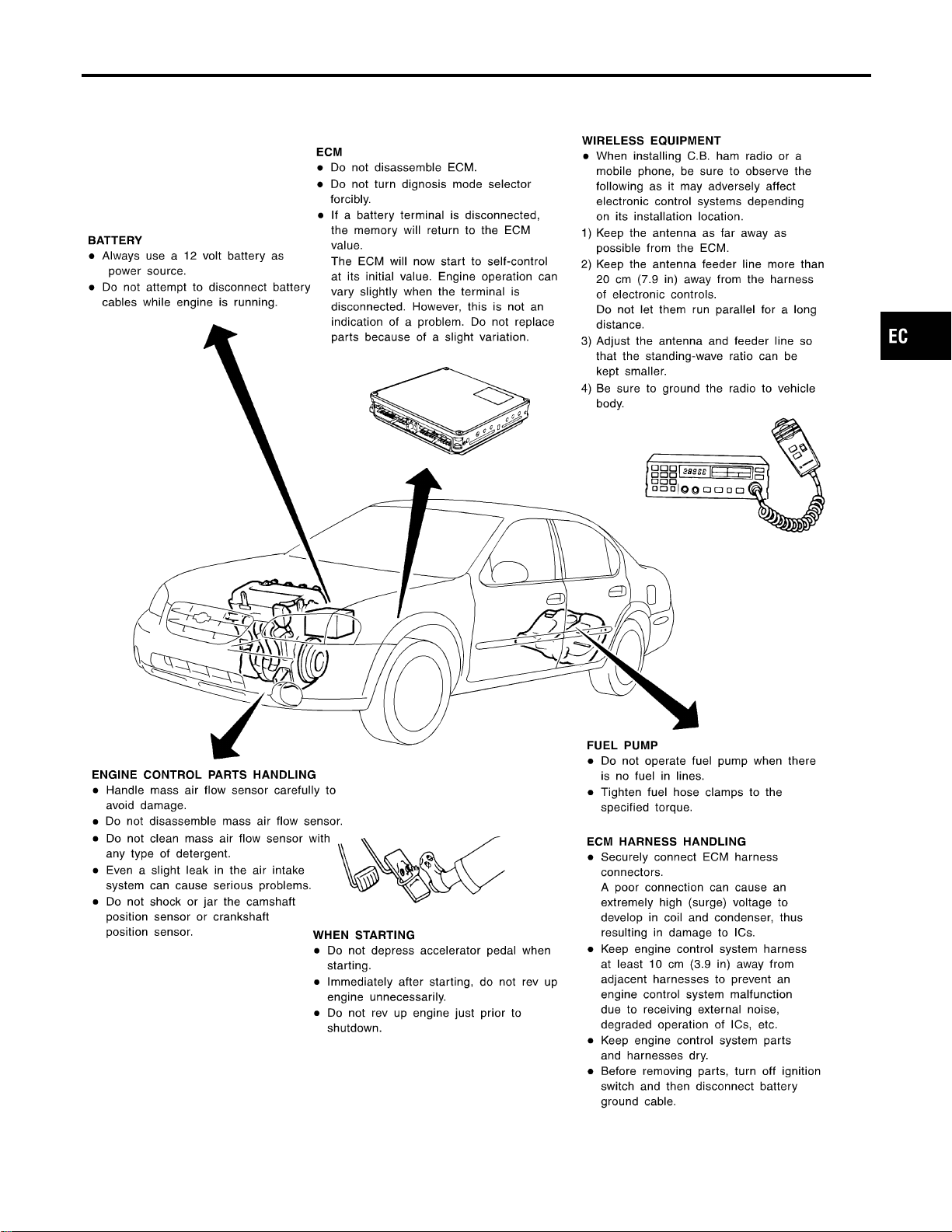
Engine Fuel & Emission Control System
NFEC0004
SEF242XD
GI
MA
EM
LC
FE
CL
MT
AT
AX
SU
BR
ST
RS
BT
HA
SC
EL
IDX
PRECAUTIONS
Engine Fuel & Emission Control System
EC-19
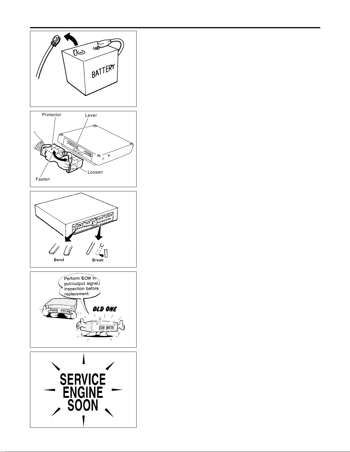
SEF289H
Precautions
NFEC0005
I Before connecting or disconnecting the ECM harness
connector, turn ignition switch OFF and disconnect nega-
tive battery terminal. Failure to do so may damage the
ECM because battery voltage is applied to ECM even if
ignition switch is turned off.
SEF908W
I When connecting ECM harness connector, fasten it
securely with a lever as far as it will go as shown at left.
SEF291H
I When connecting or disconnecting pin connectors into or
from ECM, take care not to damage pin terminals (bend or
break).
Make sure that there are not any bends or breaks on ECM
pin terminal, when connecting pin connectors.
MEF040D
I Before replacing ECM, perform “ECM Terminals and Ref-
erence Value” inspection and make sure ECM functions
properly. Refer to EC-141.
SEF217U
I After performing each TROUBLE DIAGNOSIS, perform
“DTC Confirmation Procedure” or “Overall Function
Check”.
The DTC should not be displayed in the “DTC Confirma-
tion Procedure” if the repair is completed. The “Overall
Function Check” should be a good result if the repair is
completed.
PRECAUTIONS
Precautions
EC-20
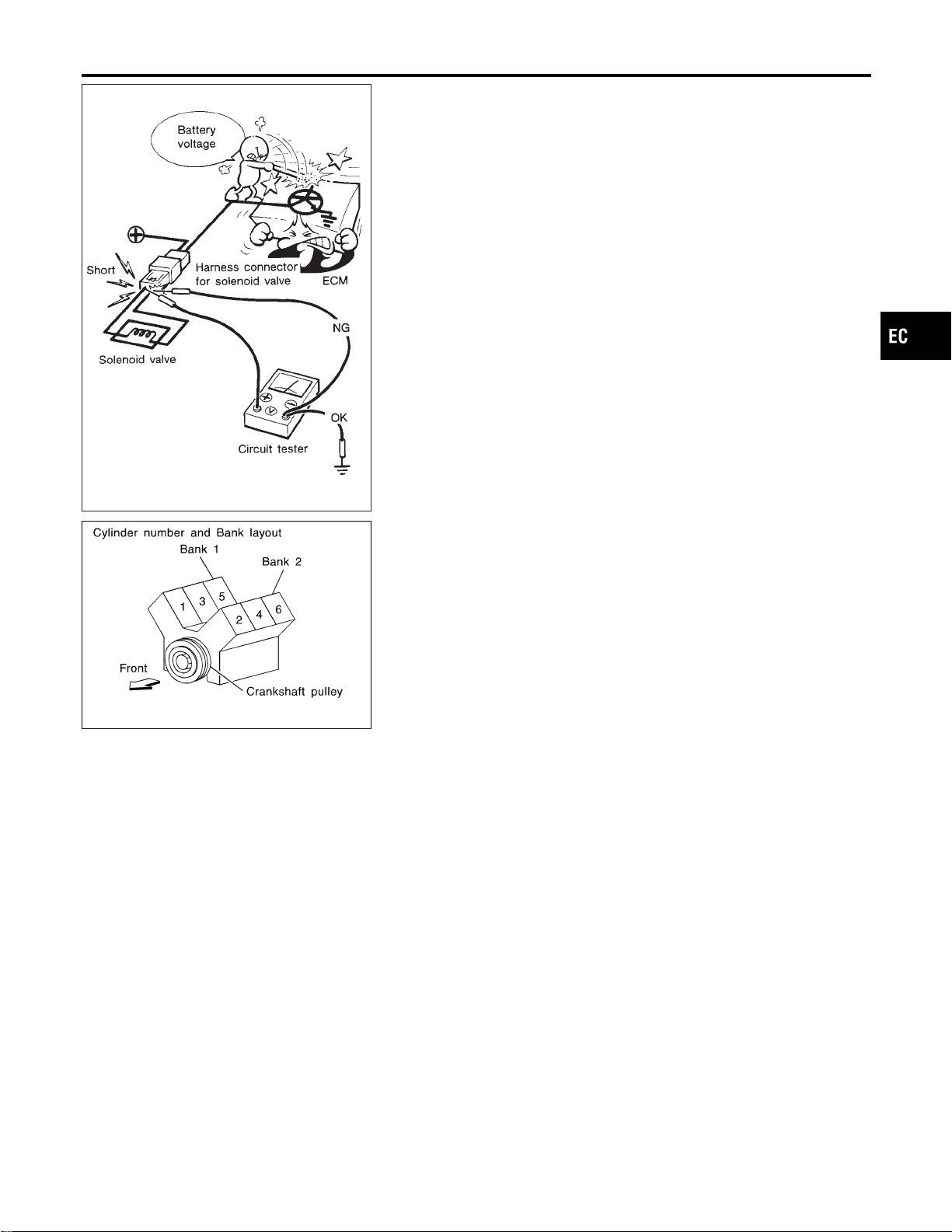
SEF348N
I When measuring ECM signals with a circuit tester, never
allow the two tester probes to contact.
Accidental contact of probes will cause a short circuit and
damage the ECM power transistor.
I Do not use ECM ground terminals when measuring input/
output voltage. Doing so may result in damage to the
ECM’s transistor. Use a ground other than the ECM
terminals, such as the ground.
SEC893C
I Regarding model A33, “B1” indicates the bank 1 and “B2”
indicates the bank 2 as shown in the figure.
I Bank 1 includes No. 1 cylinder.
Wiring Diagrams and Trouble Diagnosis
NFEC0006
When you read Wiring diagrams, refer to the following:
I GI-11, “HOW TO READ WIRING DIAGRAMS”
I EL-10, “POWER SUPPLY ROUTING” for power distribution circuit
When you perform trouble diagnosis, refer to the following:
I GI-24, “HOW TO FOLLOW TEST GROUPS IN TROUBLE DIAGNOSES”
I GI-21, “HOW TO PERFORM EFFICIENT DIAGNOSIS FOR AN ELECTRICAL INCIDENT”
GI
MA
EM
LC
FE
CL
MT
AT
AX
SU
BR
ST
RS
BT
HA
SC
EL
IDX
PRECAUTIONS
Precautions (Cont’d)
EC-21
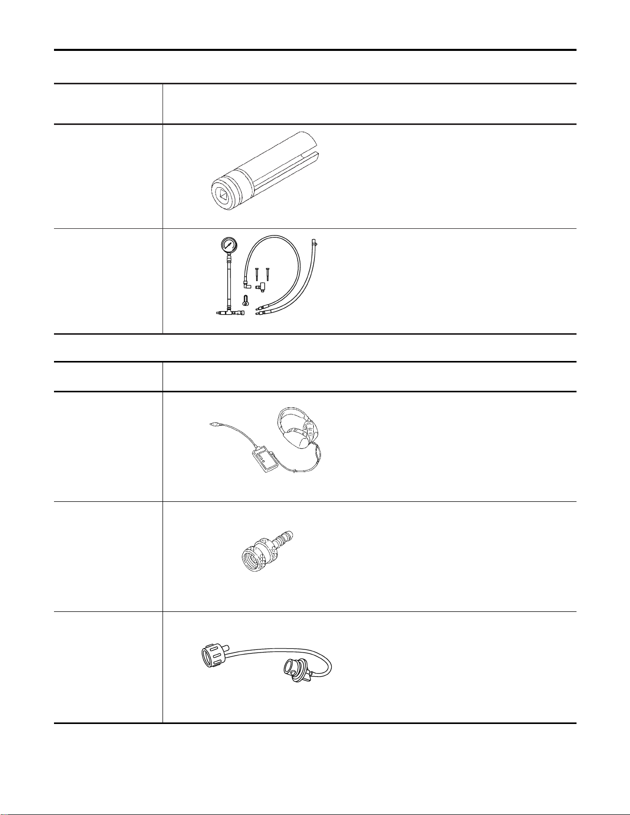
Special Service Tools
NFEC1417
The actual shapes of Kent-Moore tools may differ from those of special service tools illustrated here.
Tool number
(Kent-Moore No.)
Tool name
Description
KV10117100
(J36471-A)
Heated oxygen sensor
wrench
NT379
Loosening or tightening heated oxygen sensors
with 22 mm (0.87 in) hexagon nut
(J44321)
Fuel pressure adapter
and gauge kit
SEF326Z
Checking fuel pressure with pressure gauge
Commercial Service Tools
NFEC1418
Tool name
(Kent-Moore No.)
Description
Leak detector
ie: (J41416)
NT703
Locating the EVAP leak
EVAP service port
adapter
ie: (J41413-OBD)
NT704
Applying positive pressure through EVAP service
port
Fuel filler cap adapter
ie: (MLR-8382)
NT815
Checking fuel tank vacuum relief valve opening
pressure
PREPARATION
Special Service Tools
EC-22
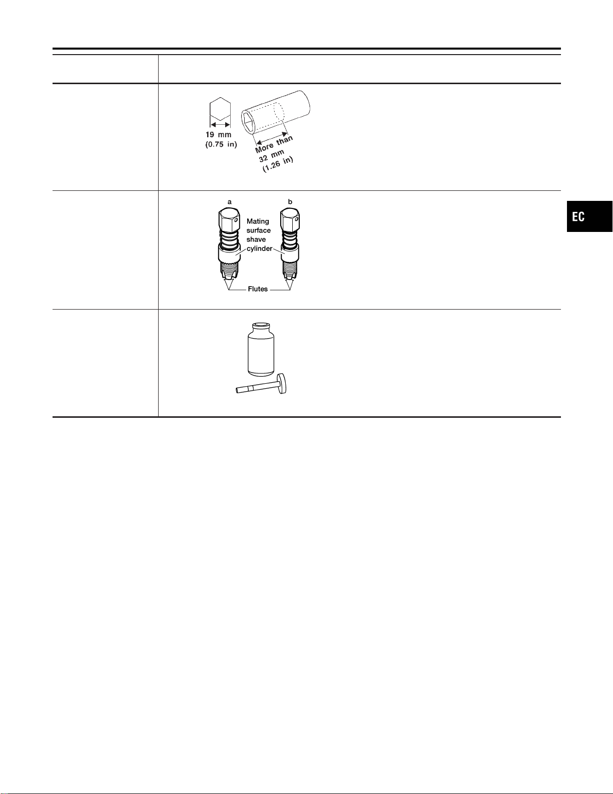
Tool name
(Kent-Moore No.)
Description
Socket wrench
NT705
Removing and installing engine coolant tempera-
ture sensor
Oxygen sensor thread
cleaner
ie: (J-43897-18)
(J-43897-12)
AEM488
Reconditioning the exhaust system threads before
installing a new oxygen sensor. Use with anti-
seize lubricant shown below.
a: J-43897-18 18 mm diameter with pitch 1.5
mm, for Zirconia Oxygen Sensor
b: J-43897-12 12 mm diameter with pitch 1.25
mm, for Titania Oxygen Sensor
Anti-seize lubricant
ie: (Permatex
TM
133AR
or equivalent meeting
MIL specification MIL-A-
907)
NT779
Lubricating oxygen sensor thread cleaning tool
when reconditioning exhaust system threads.
GI
MA
EM
LC
FE
CL
MT
AT
AX
SU
BR
ST
RS
BT
HA
SC
EL
IDX
PREPARATION
Commercial Service Tools (Cont’d)
EC-23
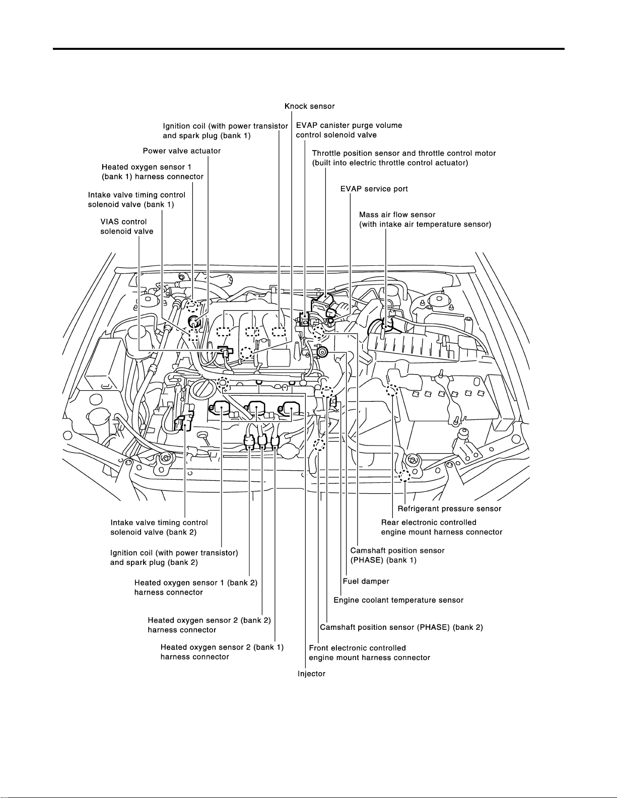
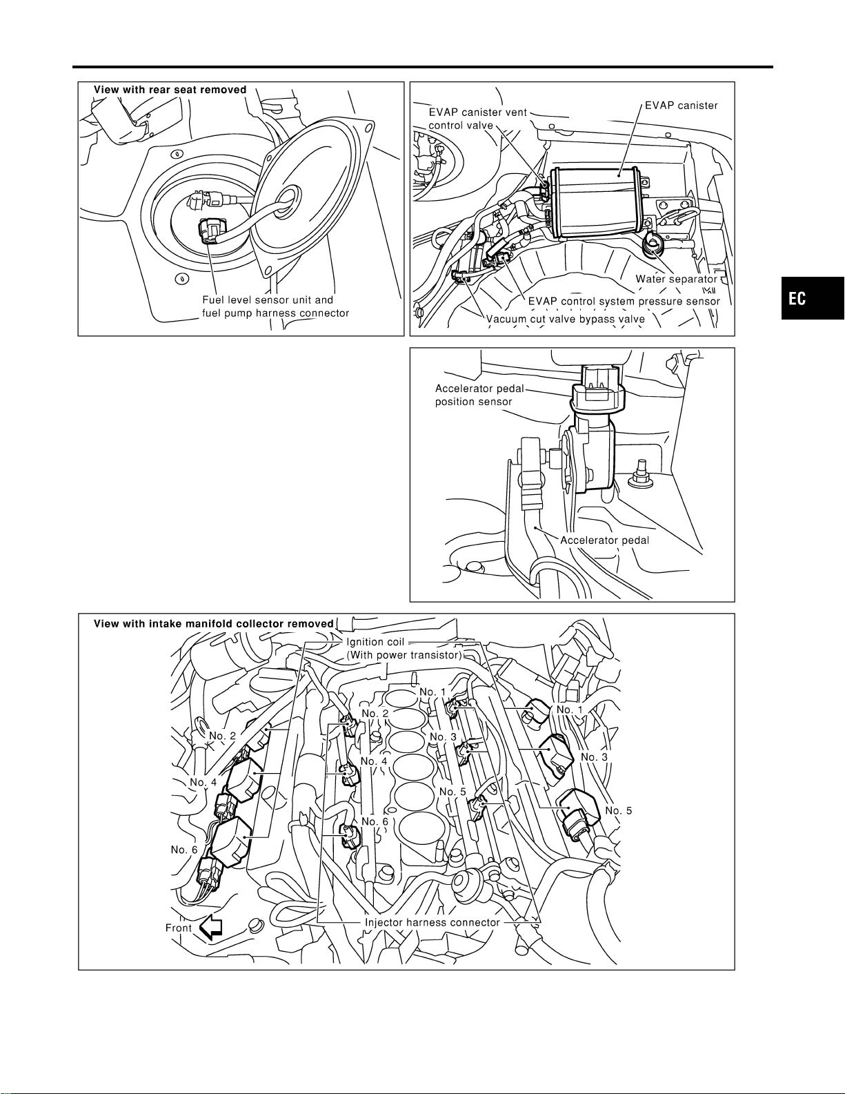
Engine Control Component Parts Location
NFEC1419
SEC993CA
ENGINE AND EMISSION CONTROL OVERALL SYSTEM
Engine Control Component Parts Location
EC-24
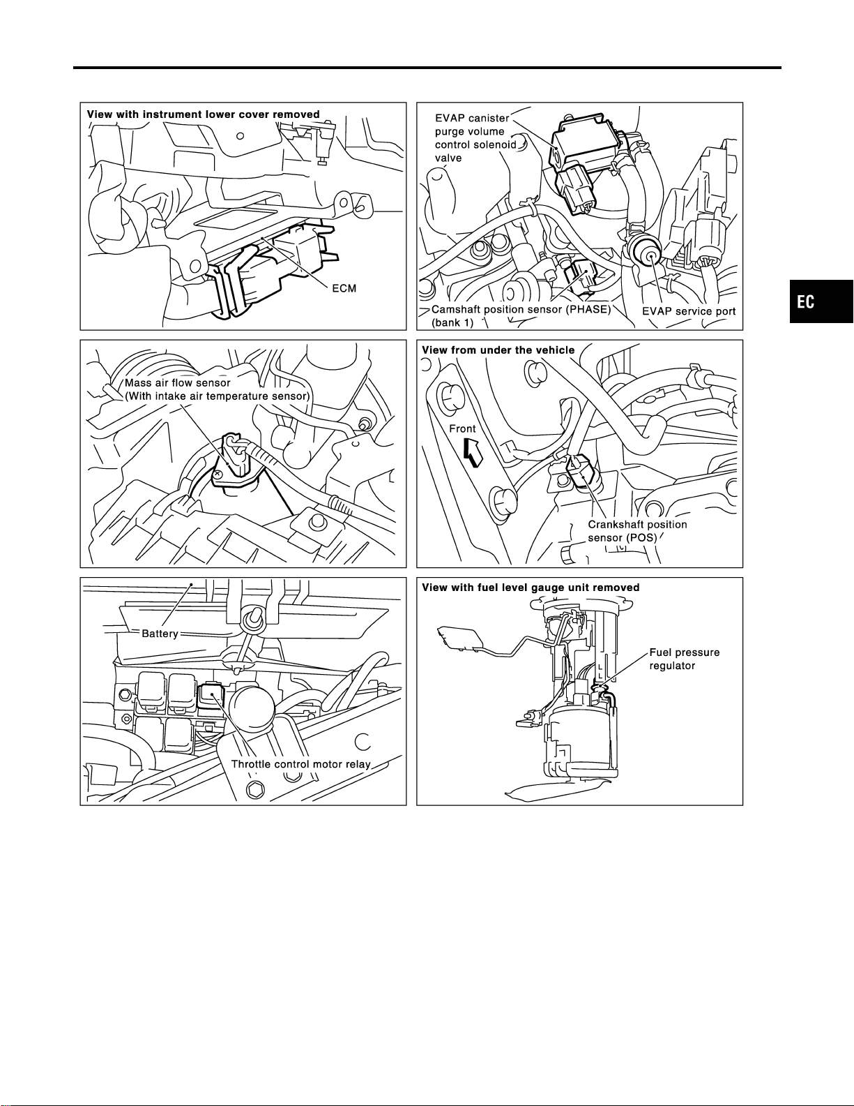
SEC994C
GI
MA
EM
LC
FE
CL
MT
AT
AX
SU
BR
ST
RS
BT
HA
SC
EL
IDX
ENGINE AND EMISSION CONTROL OVERALL SYSTEM
Engine Control Component Parts Location (Cont’d)
EC-25
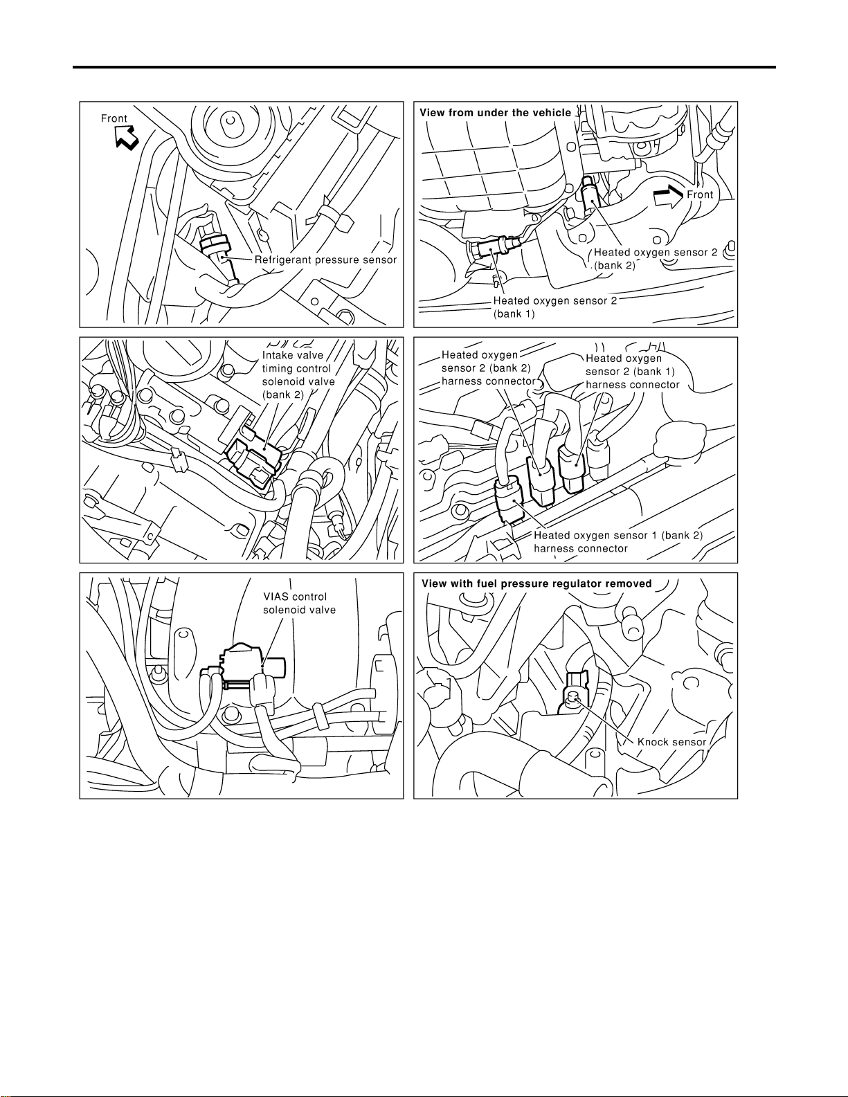
SEC995C
ENGINE AND EMISSION CONTROL OVERALL SYSTEM
Engine Control Component Parts Location (Cont’d)
EC-26
SEC996C
GI
MA
EM
LC
FE
CL
MT
AT
AX
SU
BR
ST
RS
BT
HA
SC
EL
IDX
ENGINE AND EMISSION CONTROL OVERALL SYSTEM
Engine Control Component Parts Location (Cont’d)
EC-27
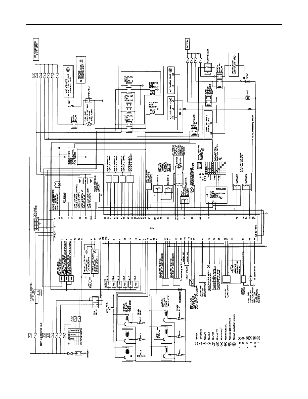
Circuit Diagram
NFEC0010
MEC920D
ENGINE AND EMISSION CONTROL OVERALL SYSTEM
Circuit Diagram
EC-28
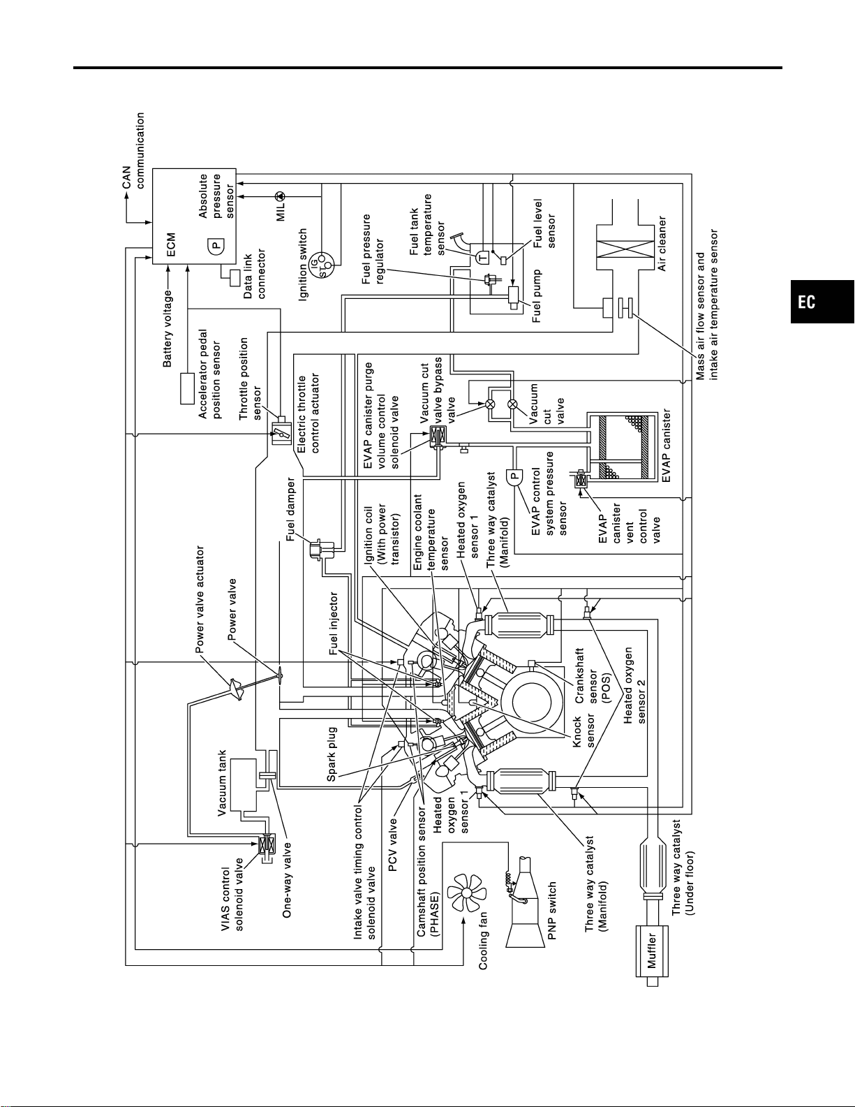
System Diagram
NFEC0011
SEC894C
GI
MA
EM
LC
FE
CL
MT
AT
AX
SU
BR
ST
RS
BT
HA
SC
EL
IDX
ENGINE AND EMISSION CONTROL OVERALL SYSTEM
System Diagram
EC-29
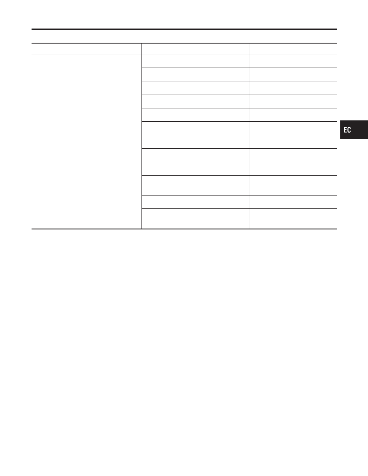
System Chart
NFEC0013
Input (Sensor) ECM Function Output (Actuator)
I Camshaft position sensor (PHASE)
I Mass air flow sensor
I Engine coolant temperature sensor
I Heated oxygen sensor 1
I Ignition switch
I Throttle position sensor
I Accelerator pedal position sensor
I Park/neutral position (PNP) switch
I Air conditioner switch
I Knock sensor
I Intake air temperature sensor
I Absolute pressure sensor
I EVAP control system pressure sensor*1
I Battery voltage
I Power steering pressure sensor
I Vehicle speed (From combination meter)
I Fuel tank temperature sensor*1
I Crankshaft position sensor (POS)
I Heated oxygen sensor 2*2
I TCM (Transmission control module)*3
I Refrigerant pressure sensor
I Electrical load
I Fuel level sensor*1
I ASCD steering switch
I ASCD brake switch
I ASCD clutch switch (MT models)
I Stop lamp switch
Fuel injection & mixture ratio control Injectors
Electronic ignition system Power transistor
Fuel pump control Fuel pump relay
On board diagnostic system MIL (On the instrument panel)
ASCD vehicle speed control Electric throttle control actuator
Cooling fan control Cooling fan relays
Power valve control VIAS control solenoid valve
Heated oxygen sensor 1 heater control Heated oxygen sensor 1 heater
Heated oxygen sensor 2 heater control Heated oxygen sensor 2 heater
EVAP canister purge flow control
EVAP canister purge volume con-
trol solenoid valve
Air conditioning cut control Air conditioner relay
ON BOARD DIAGNOSIS for EVAP system
I EVAP canister vent control valve
I Vacuum cut valve bypass valve
*1: These sensors are not used to control the engine system. They are used only for the on board diagnosis.
*2: This sensor is not used to control the engine system under normal conditions.
*3: The signals are sent to the ECM through CAN communication line.
GI
MA
EM
LC
FE
CL
MT
AT
AX
SU
BR
ST
RS
BT
HA
SC
EL
IDX
ENGINE AND EMISSION CONTROL OVERALL SYSTEM
System Chart
EC-31

Multiport Fuel Injection (MFI) System
DESCRIPTION
NFEC0014
Input/Output Signal Chart
NFEC0014S01
Sensor Input Signal to ECM
ECM func-
tion
Actuator
Crankshaft position sensor (POS)
Engine speed
Piston position
Fuel injec-
tion & mix-
ture ratio
control
Injectors
Camshaft position sensor (PHASE)
Mass air flow sensor Amount of intake air
Engine coolant temperature sensor Engine coolant temperature
Heated oxygen sensor 1 Density of oxygen in exhaust gas
Throttle position sensor Throttle position
Accelerator pedal position sensor Accelerator pedal position
Park/neutral position (PNP) switch Gear position
Vehicle speed (From combination meter) Vehicle speed
Ignition switch Start signal
Air conditioner switch Air conditioner operation
Knock sensor Engine knocking condition
Battery Battery voltage
Absolute pressure sensor Ambient air barometric pressure
Power steering pressure sensor Power steering operation
Heated oxygen sensor 2* Density of oxygen in exhaust gas
*: Under normal conditions, this sensor is not for engine control operation.
Basic Multiport Fuel Injection System
NFEC0014S02
The amount of fuel injected from the fuel injector is determined by the ECM. The ECM controls the length of
time the valve remains open (injection pulse duration). The amount of fuel injected is a program value in the
ECM memory. The program value is preset by engine operating conditions. These conditions are determined
by input signals (for engine speed and intake air) from both the crankshaft position sensor and the mass air
flow sensor.
Various Fuel Injection Increase/Decrease Compensation
NFEC0014S03
In addition, the amount of fuel injected is compensated to improve engine performance under various oper-
ating conditions as listed below.
<Fuel increase>
I During warm-up
I When starting the engine
I During acceleration
I Hot-engine operation
I When selector lever is changed from “N” to “D”
I High-load, high-speed operation
<Fuel decrease>
I During deceleration
I During high engine speed operation
ENGINE AND EMISSION BASIC CONTROL SYSTEM DESCRIPTION
Multiport Fuel Injection (MFI) System
EC-32
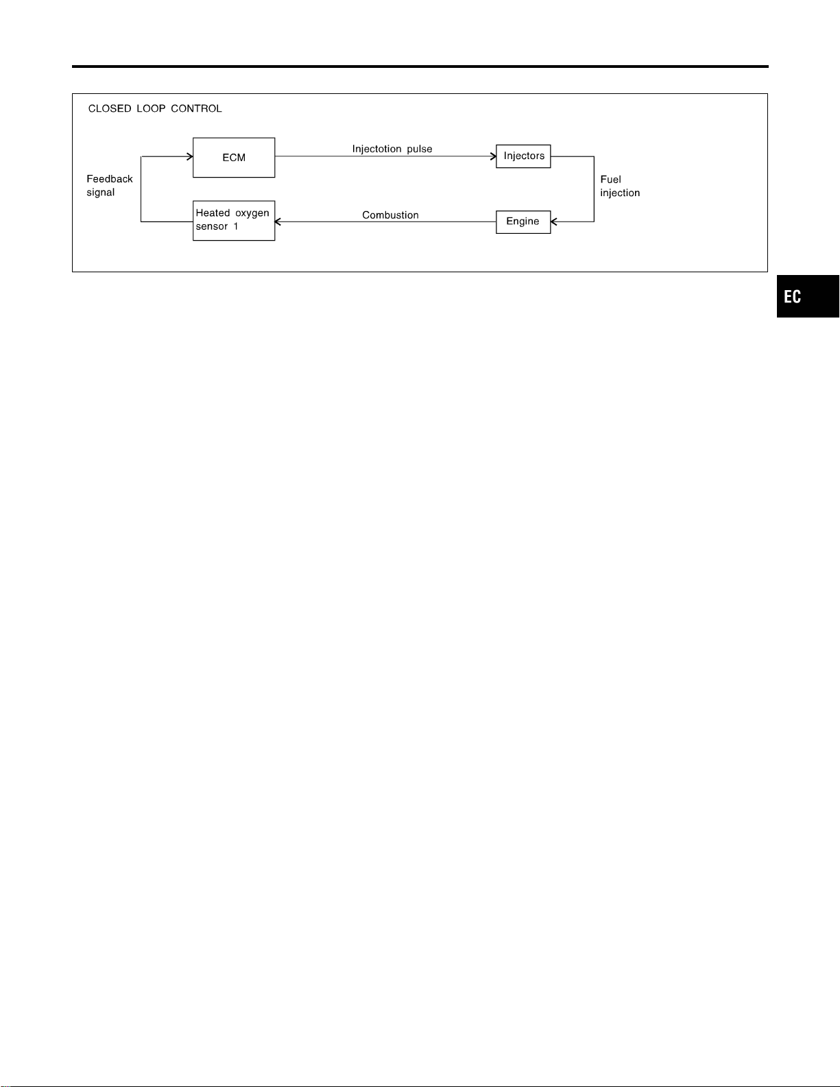
Mixture Ratio Feedback Control (Closed loop control)
NFEC0014S04
SEF336WC
The mixture ratio feedback system provides the best air-fuel mixture ratio for driveability and emission con-
trol. The warm-up three way catalyst can then better reduce CO, HC and NOx emissions. This system uses
a heated oxygen sensor 1 in the exhaust manifold to monitor if the engine operation is rich or lean. The ECM
adjusts the injection pulse width according to the sensor voltage signal. For more information about the heated
oxygen sensor 1, refer to EC-240. This maintains the mixture ratio within the range of stoichiometric (ideal
air-fuel mixture).
This stage is referred to as the closed loop control condition.
Heated oxygen sensor 2 is located downstream of the warm-up three way catalyst. Even if the switching
characteristics of the heated oxygen sensor 1 shift, the air-fuel ratio is controlled to stoichiometric by the sig-
nal from the heated oxygen sensor 2.
Open Loop Control
NFEC0014S05
The open loop system condition refers to when the ECM detects any of the following conditions. Feedback
control stops in order to maintain stabilized fuel combustion.
I Deceleration and acceleration
I High-load, high-speed operation
I Malfunction of heated oxygen sensor 1 or its circuit
I Insufficient activation of heated oxygen sensor 1 at low engine coolant temperature
I High engine coolant temperature
I During warm-up
I After shifting from “N” to “D”
I When starting the engine
Mixture Ratio Self-learning Control
NFEC0014S06
The mixture ratio feedback control system monitors the mixture ratio signal transmitted from the heated oxy-
gen sensor 1. This feedback signal is then sent to the ECM. The ECM controls the basic mixture ratio as close
to the theoretical mixture ratio as possible. However, the basic mixture ratio is not necessarily controlled as
originally designed. Both manufacturing differences (i.e., mass air flow sensor hot wire) and characteristic
changes during operation (i.e., injector clogging) directly affect mixture ratio.
Accordingly, the difference between the basic and theoretical mixture ratios is monitored in this system. This
is then computed in terms of “injection pulse duration” to automatically compensate for the difference between
the two ratios.
“Fuel trim” refers to the feedback compensation value compared against the basic injection duration. Fuel trim
includes short term fuel trim and long term fuel trim.
“Short term fuel trim” is the short-term fuel compensation used to maintain the mixture ratio at its theoretical
value. The signal from the heated oxygen sensor 1 indicates whether the mixture ratio is RICH or LEAN com-
pared to the theoretical value. The signal then triggers a reduction in fuel volume if the mixture ratio is rich,
and an increase in fuel volume if it is lean.
“Long term fuel trim” is overall fuel compensation carried out long-term to compensate for continual deviation
of the short term fuel trim from the central value. Such deviation will occur due to individual engine differences,
wear over time and changes in the usage environment.
GI
MA
EM
LC
FE
CL
MT
AT
AX
SU
BR
ST
RS
BT
HA
SC
EL
IDX
ENGINE AND EMISSION BASIC CONTROL SYSTEM DESCRIPTION
Multiport Fuel Injection (MFI) System (Cont’d)
EC-33
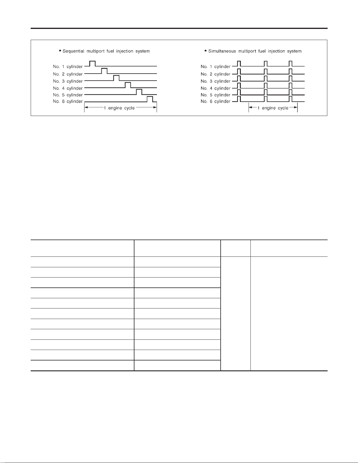
Fuel Injection Timing
NFEC0014S07
SEF179U
Two types of systems are used.
Sequential Multiport Fuel Injection System
NFEC0014S0701
Fuel is injected into each cylinder during each engine cycle according to the firing order. This system is used
when the engine is running.
Simultaneous Multiport Fuel Injection System
NFEC0014S0702
Fuel is injected simultaneously into all six cylinders twice each engine cycle. In other words, pulse signals of
the same width are simultaneously transmitted from the ECM.
The six injectors will then receive the signals two times for each engine cycle.
This system is used when the engine is being started and/or if the fail-safe system (CPU) is operating.
Fuel Shut-off
NFEC0014S08
Fuel to each cylinder is cut off during deceleration or operation of the engine at excessively high speeds.
Electronic Ignition (EI) System
DESCRIPTION
NFEC0015
Input/Output Signal Chart
NFEC0015S01
Sensor Input Signal to ECM
ECM func-
tion
Actuator
Crankshaft position sensor (POS) Engine speed
Ignition tim-
ing control
Power transistor
Camshaft position sensor (PHASE) Piston position
Mass air flow sensor Amount of intake air
Engine coolant temperature sensor Engine coolant temperature
Throttle position sensor Throttle position
Accelerator pedal position sensor Accelerator pedal position
Vehicle speed (From combination meter) Vehicle speed
Ignition switch Start signal
Knock sensor Engine knocking
Park/neutral position (PNP) switch Gear position
Battery Battery voltage
ENGINE AND EMISSION BASIC CONTROL SYSTEM DESCRIPTION
Multiport Fuel Injection (MFI) System (Cont’d)
EC-34
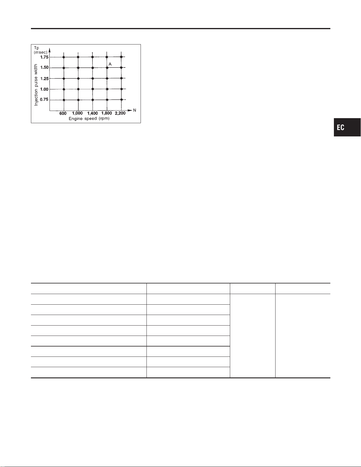
System Description
NFEC0015S02
SEF742M
The ignition timing is controlled by the ECM to maintain the best air-fuel ratio for every running condition of
the engine. The ignition timing data is stored in the ECM. This data forms the map shown.
The ECM receives information such as the injection pulse width and camshaft position sensor signal. Com-
puting this information, ignition signals are transmitted to the power transistor.
e.g., N: 1,800 rpm, Tp: 1.50 msec
A °BTDC
During the following conditions, the ignition timing is revised by the ECM according to the other data stored
in the ECM.
I At starting
I During warm-up
I At idle
I At low battery voltage
I During acceleration
The knock sensor retard system is designed only for emergencies. The basic ignition timing is programmed
within the anti-knocking zone, if recommended fuel is used under dry conditions. The retard system does not
operate under normal driving conditions. If engine knocking occurs, the knock sensor monitors the condition.
The signal is transmitted to the ECM. The ECM retards the ignition timing to eliminate the knocking condition.
Air Conditioning Cut Control
DESCRIPTION
NFEC0016
Input/Output Signal Chart
NFEC0016S01
Sensor Input Signal to ECM ECM function Actuator
Air conditioner switch Air conditioner “ON” signal
Air conditioner cut
control
Air conditioner relay
Throttle position sensor Throttle valve opening angle
Crankshaft position sensor (POS) Engine speed
Engine coolant temperature sensor Engine coolant temperature
Ignition switch Start signal
Vehicle speed (From combination meter) Vehicle speed
Refrigerant pressure sensor Refrigerant pressure
Power steering pressure sensor Power steering operation
System Description
NFEC0016S02
This system improves engine operation when the air conditioner is used.
Under the following conditions, the air conditioner is turned off.
I When the accelerator pedal is fully depressed.
I When cranking the engine.
I At high engine speeds.
I When the engine coolant temperature becomes excessively high.
I When operating power steering during low engine speed or low vehicle speed.
GI
MA
EM
LC
FE
CL
MT
AT
AX
SU
BR
ST
RS
BT
HA
SC
EL
IDX
ENGINE AND EMISSION BASIC CONTROL SYSTEM DESCRIPTION
Electronic Ignition (EI) System (Cont’d)
EC-35
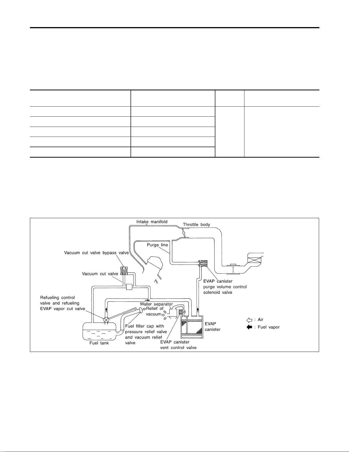
I When engine speed is excessively low.
I When refrigerant pressure is excessively low or high.
Fuel Cut Control (at no load & high engine
speed)
DESCRIPTION
NFEC0017
Input/Output Signal Chart
NFEC0017S01
Sensor Input Signal to ECM
ECM func-
tion
Actuator
Vehicle speed (From combination meter) Vehicle speed
Fuel cut
control
Injectors
Park/neutral position (PNP) switch Neutral position
Throttle position sensor Throttle position
Engine coolant temperature sensor Engine coolant temperature
Crankshaft position sensor (POS) Engine speed
If the engine speed is above 1,800 rpm with no load (for example, in neutral and engine speed over 1,800
rpm) fuel will be cut off after some time. The exact time when the fuel is cut off varies based on engine speed.
Fuel cut will operate until the engine speed reaches 1,500 rpm, then fuel cut is cancelled.
NOTE:
This function is different from deceleration control listed under “Multiport Fuel Injection (MFI) System”, EC-32.
Evaporative Emission System
DESCRIPTION
NFEC0018
SEF569XA
The evaporative emission system is used to reduce hydrocarbons emitted into the atmosphere from the fuel
system. This reduction of hydrocarbons is accomplished by activated charcoals in the EVAP canister.
The fuel vapor in the sealed fuel tank is led into the EVAP canister which contains activated carbon and the
vapor is stored there when the engine is not operating or when refueling to the fuel tank.
The vapor in the EVAP canister is purged by the air through the purge line to the intake manifold when the
engine is operating. EVAP canister purge volume control solenoid valve is controlled by ECM. When the engine
operates, the flow rate of vapor controlled by EVAP canister purge volume control solenoid valve is propor-
tionally regulated as the air flow increases.
EVAP canister purge volume control solenoid valve also shuts off the vapor purge line during decelerating and
idling.
ENGINE AND EMISSION BASIC CONTROL SYSTEM DESCRIPTION
Air Conditioning Cut Control (Cont’d)
EC-36
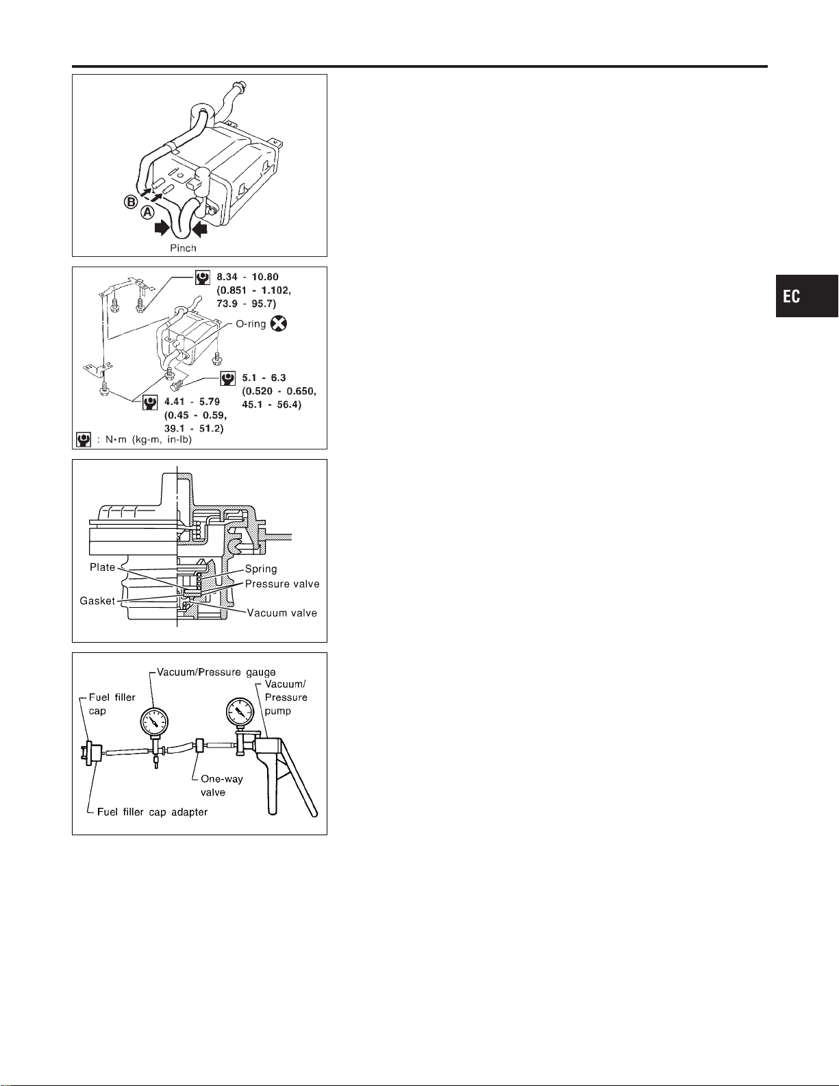
SEF396T
INSPECTION
NFEC0019
EVAP Canister
NFEC0019S01
Check EVAP canister as follows:
1. Pinch the fresh air hose.
2. Blow air into port A and check that it flows freely out of port B.
SEF397T
Tightening Torque
NFEC0019S02
Tighten EVAP canister as shown in the figure.
Make sure new O-ring is installed properly between EVAP can-
ister and EVAP canister vent control valve.
SEF445Y
SEF943S
Fuel Tank Vacuum Relief Valve (Built into fuel filler cap)
NFEC0019S03
1. Wipe clean valve housing.
2. Check valve opening pressure and vacuum.
Pressure:
15.3 - 20.0 kPa (0.156 - 0.204 kg/cm
2
, 2.22 - 2.90 psi)
Vacuum:
−6.0 to −3.3 kPa (−0.061 to −0.034 kg/cm
2
, −0.87 to
−0.48 psi)
3. If out of specification, replace fuel filler cap as an assembly.
CAUTION:
Use only a genuine fuel filler cap as a replacement. If an incor-
rect fuel filler cap is used, the MIL may come on.
Vacuum Cut Valve and Vacuum Cut Valve Bypass Valve
NFEC0019S04
Refer to EC-628.
EVAP Canister Purge Volume Control Solenoid Valve
NFEC0019S05
Refer to EC-376.
Fuel Tank Temperature Sensor
NFEC0019S06
Refer to EC-285.
GI
MA
EM
LC
FE
CL
MT
AT
AX
SU
BR
ST
RS
BT
HA
SC
EL
IDX
ENGINE AND EMISSION BASIC CONTROL SYSTEM DESCRIPTION
Evaporative Emission System (Cont’d)
EC-37
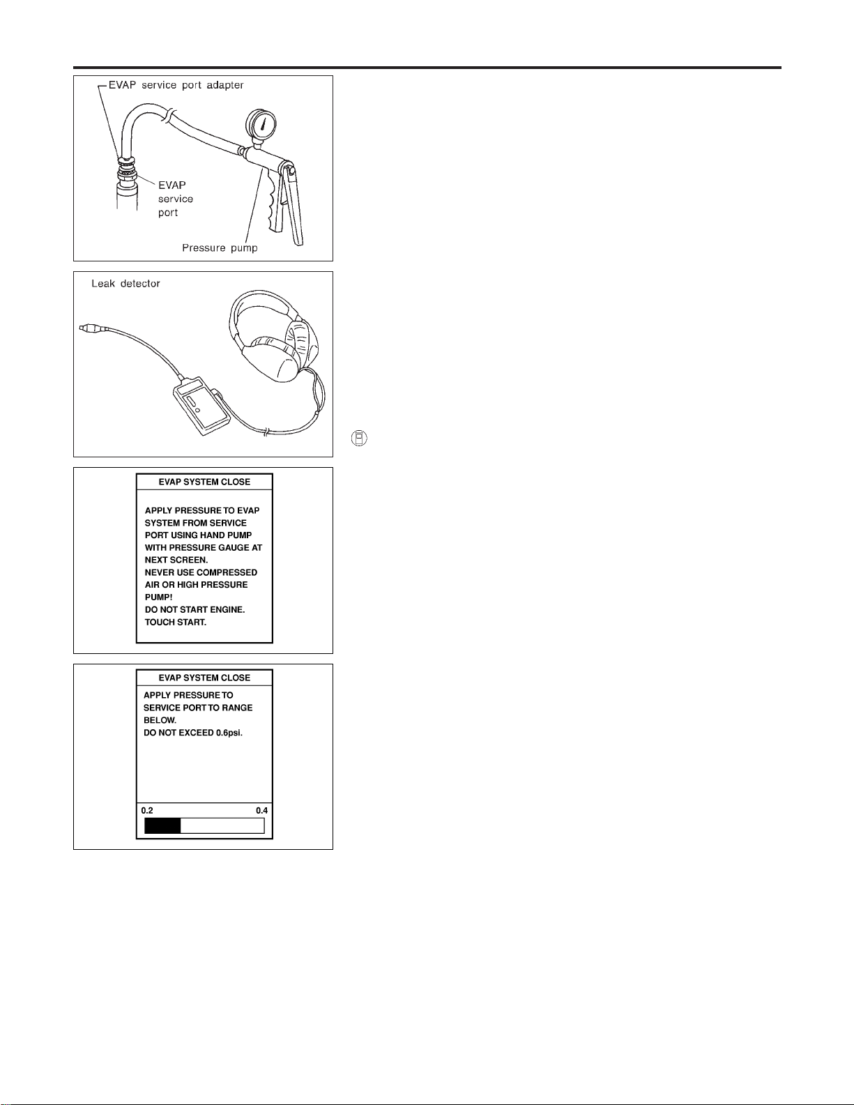
SEF462UA
Evap Service Port
NFEC0019S07
Positive pressure is delivered to the EVAP system through the
EVAP service port. If fuel vapor leakage in the EVAP system
occurs, use a leak detector to locate the leak.
SEF200U
PEF838U
PEF917U
How to Detect Fuel Vapor Leakage
NFEC0019S08
CAUTION:
I Never use compressed air or a high pressure pump.
I Do not exceed 4.12 kPa (0.042 kg/cm
2
, 0.6 psi) of pressure
in EVAP system.
NOTE:
I Do not start engine.
I Improper installation of EVAP service port adapter to the EVAP
service port may cause a leak.
With CONSULT-II
NFEC0019S0801
1) Attach the EVAP service port adapter securely to the EVAP
service port.
2) Also attach the pressure pump and hose to the EVAP service
port adapter.
3) Turn ignition switch “ON”.
4) Select the “EVAP SYSTEM CLOSE” of “WORK SUPPORT
MODE” with CONSULT-II.
5) Touch “START”. A bar graph (Pressure indicating display) will
appear on the screen.
6) Apply positive pressure to the EVAP system until the pressure
indicator reaches the middle of the bar graph.
7) Remove EVAP service port adapter and hose with pressure
pump.
8) Locate the leak using a leak detector. Refer to “EVAPORATIVE
EMISSION LINE DRAWING”, EC-40.
ENGINE AND EMISSION BASIC CONTROL SYSTEM DESCRIPTION
Evaporative Emission System (Cont’d)
EC-38

SEF462UA
SEF254X
Without CONSULT-II
NFEC0019S0802
1) Attach the EVAP service port adapter securely to the EVAP
service port.
2) Also attach the pressure pump with pressure gauge to the
EVAP service port adapter.
3) Apply battery voltage to between the terminals of both EVAP
canister vent control valve and vacuum cut valve bypass valve
to make a closed EVAP system.
4) To locate the leak, deliver positive pressure to the EVAP sys-
tem until pressure gauge points reach 1.38 to 2.76 kPa (0.014
to 0.028 kg/cm
2
, 0.2 to 0.4 psi).
5) Remove EVAP service port adapter and hose with pressure
pump.
6) Locate the leak using a leak detector. Refer to “EVAPORATIVE
EMISSION LINE DRAWING”, EC-40.
GI
MA
EM
LC
FE
CL
MT
AT
AX
SU
BR
ST
RS
BT
HA
SC
EL
IDX
ENGINE AND EMISSION BASIC CONTROL SYSTEM DESCRIPTION
Evaporative Emission System (Cont’d)
EC-39
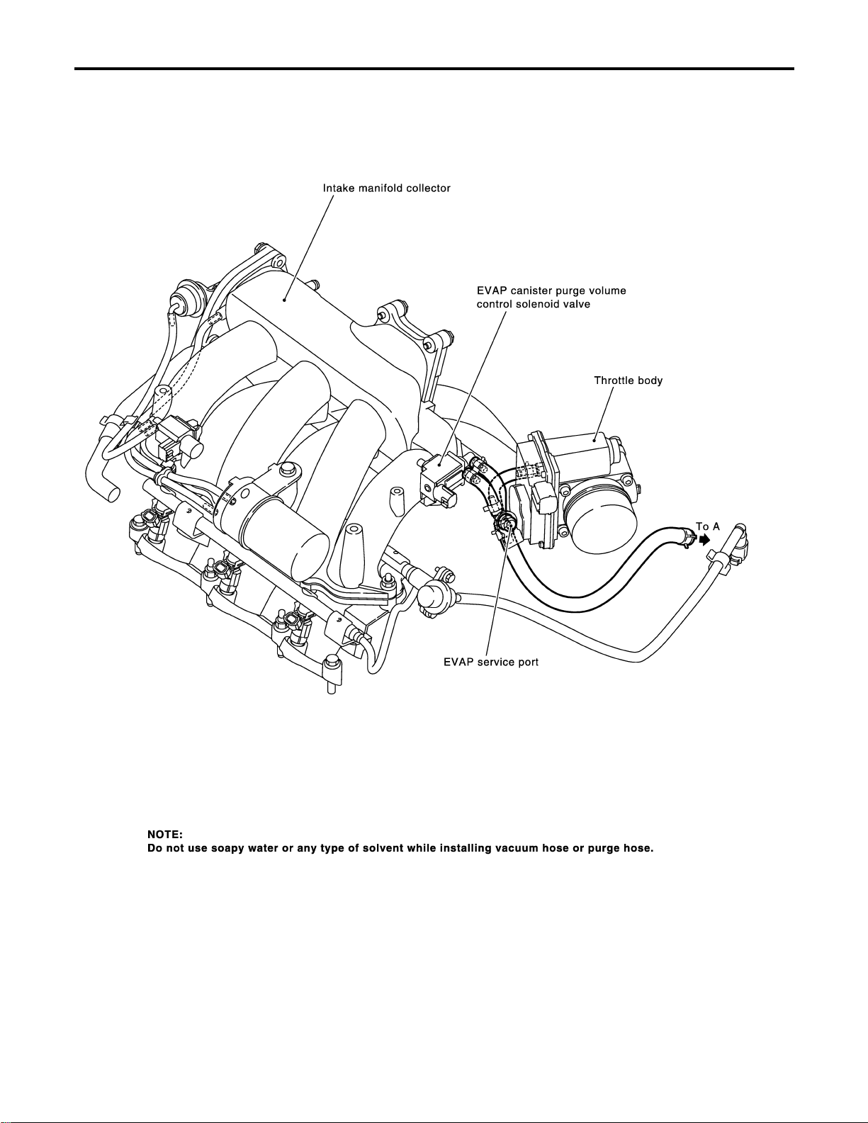
EVAPORATIVE EMISSION LINE DRAWING
NFEC1421
SEC896CA
ENGINE AND EMISSION BASIC CONTROL SYSTEM DESCRIPTION
Evaporative Emission System (Cont’d)
EC-40
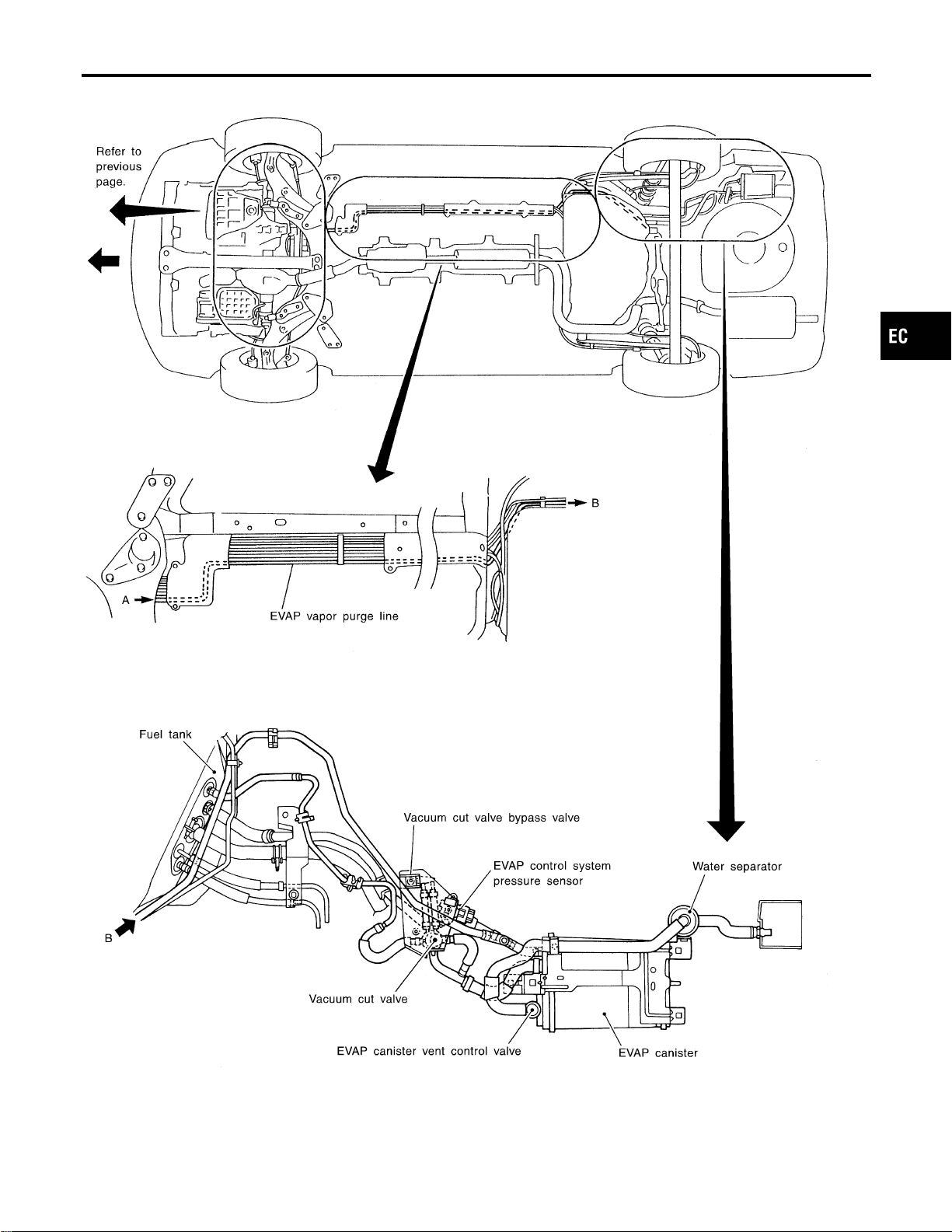
SEF253XA
GI
MA
EM
LC
FE
CL
MT
AT
AX
SU
BR
ST
RS
BT
HA
SC
EL
IDX
ENGINE AND EMISSION BASIC CONTROL SYSTEM DESCRIPTION
Evaporative Emission System (Cont’d)
EC-41
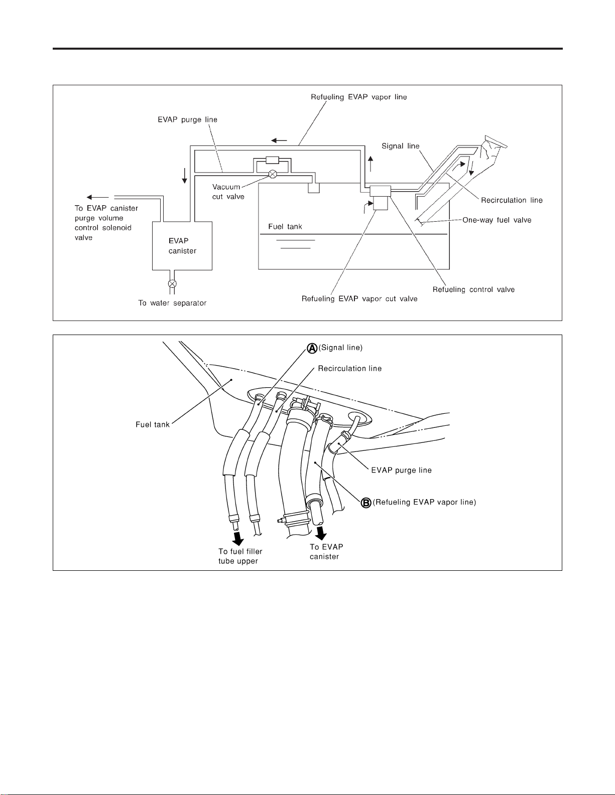
On Board Refueling Vapor Recovery (ORVR)
NFEC0744
SYSTEM DESCRIPTION
NFEC0744S01
SEF206VA
SEF830X
From the beginning of refueling, the fuel tank pressure goes up. When the pressure reaches the setting value
of the refueling control valve (RCV) opening pressure, the RCV is opened.After RCV opens, the air and vapor
inside the fuel tank go through refueling EVAP vapor cut valve, RCV and refueling vapor line to the EVAP
canister. The vapor is absorbed by the EVAP canister and the air is released to the atmosphere.
When the refueling has reached the full level of the fuel tank, the refueling EVAP vapor cut valve is closed
and refueling is stopped because of auto shut-off. The vapor which was absorbed by the EVAP canister is
purged during driving.
The RCV is always closed during driving and the evaporative emission control system is operated the same
as conventional system.
WARNING:
When conducting inspections below, be sure to observe the following:
I Put a “CAUTION: INFLAMMABLE” sign in workshop.
I Do not smoke while servicing fuel system. Keep open flames and sparks away from work area.
I Be sure to furnish the workshop with a CO
2
fire extinguisher.
ENGINE AND EMISSION BASIC CONTROL SYSTEM DESCRIPTION
On Board Refueling Vapor Recovery (ORVR)
EC-42
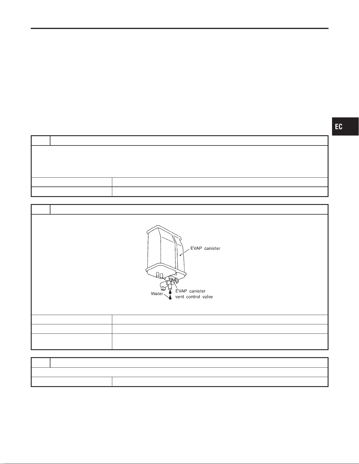
CAUTION:
I Before removing fuel line parts, carry out the following procedures:
a) Put drained fuel in an explosion-proof container and put lid on securely.
b) Release fuel pressure from fuel line. Refer to “Fuel Pressure Release”, EC-56.
c) Disconnect battery ground cable.
I Always replace O-ring when the fuel gauge retainer is removed.
I Do not kink or twist hose and tube when they are installed.
I Do not tighten hose and clamps excessively to avoid damaging hoses.
I After installation, run engine and check for fuel leaks at connection.
I Do not attempt to top off the fuel tank after the fuel pump nozzle shuts off automatically.
Continued refueling may cause fuel overflow, resulting in fuel spray and possibly a fire.
DIAGNOSTIC PROCEDURE
NFEC0744S02
Symptom: Fuel Odor from EVAP Canister Is Strong.
NFEC0744S0201
1 CHECK EVAP CANISTER
1. Remove EVAP canister with EVAP canister vent control valve attached.
2. Weigh the EVAP canister with EVAP canister vent control valve attached.
The weight should be less than 1.8 kg (4.0 lb).
OK or NG
OK © GO TO 2.
NG © GO TO 3.
2 CHECK IF EVAP CANISTER SATURATED WITH WATER
Does water drain from the EVAP canister?
SEF596U
YesorNo
Yes © GO TO 3.
No (With CONSULT-II) © GO TO 6.
No (Without CONSULT-
II)
© GO TO 7.
3 REPLACE EVAP CANISTER
Replace EVAP canister with a new one.
© GO TO 4.
GI
MA
EM
LC
FE
CL
MT
AT
AX
SU
BR
ST
RS
BT
HA
SC
EL
IDX
ENGINE AND EMISSION BASIC CONTROL SYSTEM DESCRIPTION
On Board Refueling Vapor Recovery (ORVR) (Cont’d)
EC-43
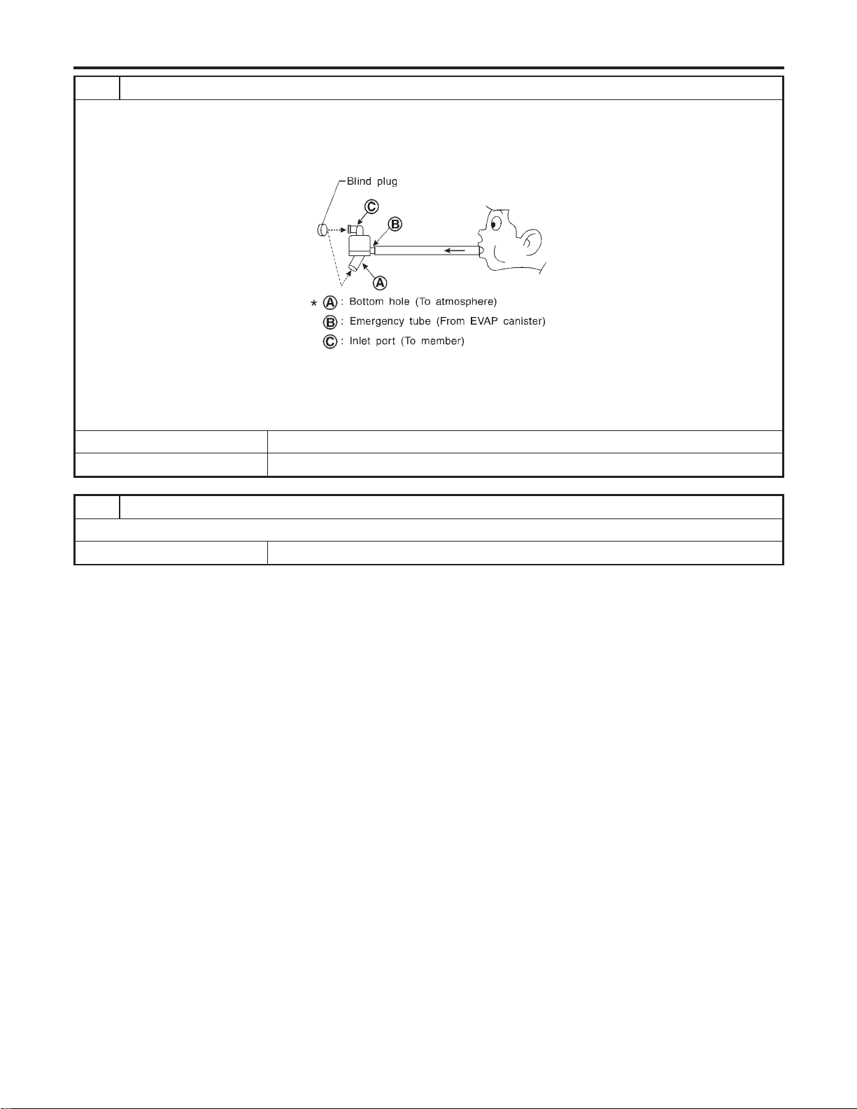
4 CHECK WATER SEPARATOR
1. Check visually for insect nests in the water separator air inlet.
2. Check visually for cracks or flaws in the appearance.
3. Check visually for cracks or flaws in the hose.
4. Check that A and C are not clogged by blowing air into B with A, and then C plugged.
SEF829T
5. In case of NG in items2-4,replace the parts.
NOTE:
I Do not disassemble water separator.
OK or NG
OK © GO TO 5.
NG © Replace water separator.
5 DETECT MALFUNCTIONING PART
Check the EVAP hose between EVAP canister and water separator for clogging or poor connection.
© Repair or replace EVAP hose.
ENGINE AND EMISSION BASIC CONTROL SYSTEM DESCRIPTION
On Board Refueling Vapor Recovery (ORVR) (Cont’d)
EC-44
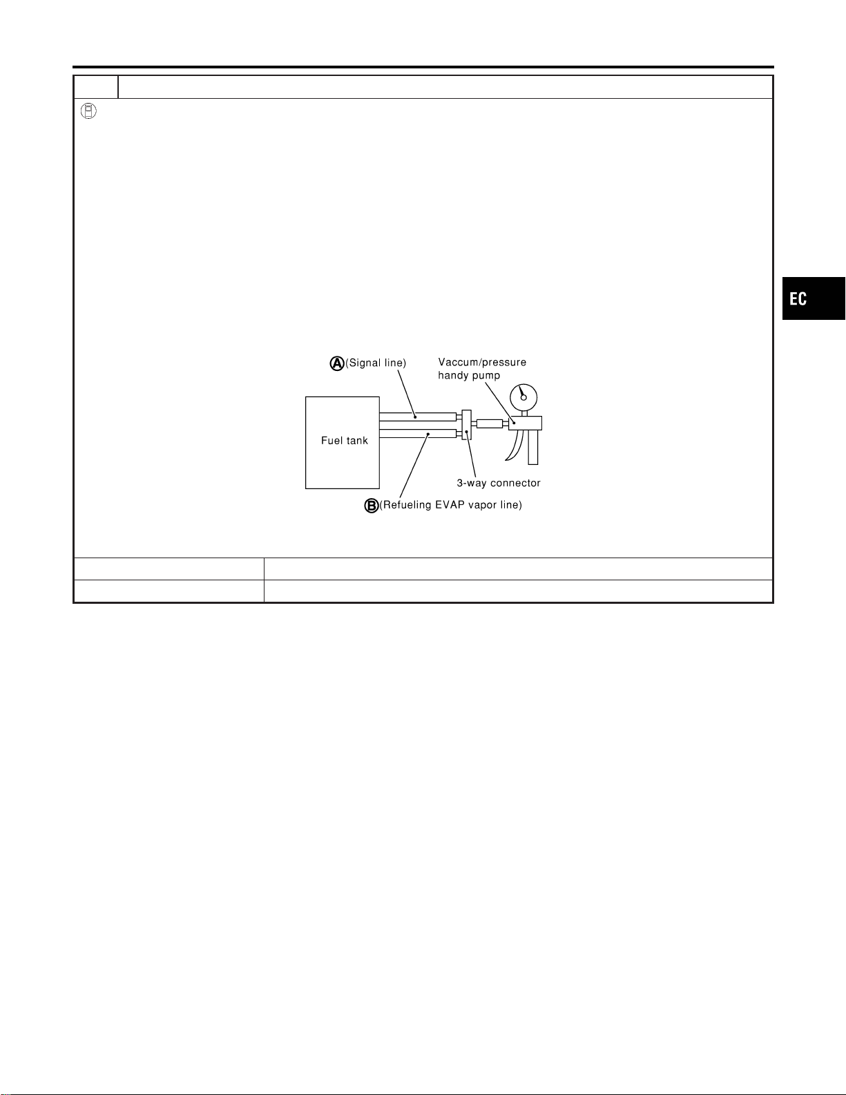
6 CHECK REFUELING EVAP VAPOR CUT VALVE
With CONSULT-II
1. Remove fuel tank. Refer to FE-4, “FUEL SYSTEM”.
2. Drain fuel from the tank as follows:
a. Remove fuel feed hose located on the fuel gauge retainer.
b. Connect a spare fuel hose, one side to fuel gauge retainer where the hose was removed and the other side to a fuel
container.
c. Drain fuel using “FUEL PUMP RELAY” in “ACTIVE TEST” mode with CONSULT-II.
3. Check refueling EVAP vapor cut valve for being stuck to close as follows.
Blow air into the refueling EVAP vapor cut valve (from hose end B), and check that the air flows freely into the tank.
4. Check EVAP vapor cut valve for being stuck to open as follows.
a. Connect vacuum pump to hose ends A and B using a suitable 3-way connector.
b. Remove fuel gauge retainer with fuel gauge unit.
Always replace O-ring with new one.
c. Put fuel tank upside down.
d. Apply vacuum pressure to both hose ends A and B [−13.3 kPa (−100 mmHg, −3.94 inHg)] with fuel gauge retainer
remaining open and check that the pressure is applicable.
SEF968X
OK or NG
OK © GO TO 8.
NG © Replace refueling EVAP vapor cut valve with fuel tank.
GI
MA
EM
LC
FE
CL
MT
AT
AX
SU
BR
ST
RS
BT
HA
SC
EL
IDX
ENGINE AND EMISSION BASIC CONTROL SYSTEM DESCRIPTION
On Board Refueling Vapor Recovery (ORVR) (Cont’d)
EC-45
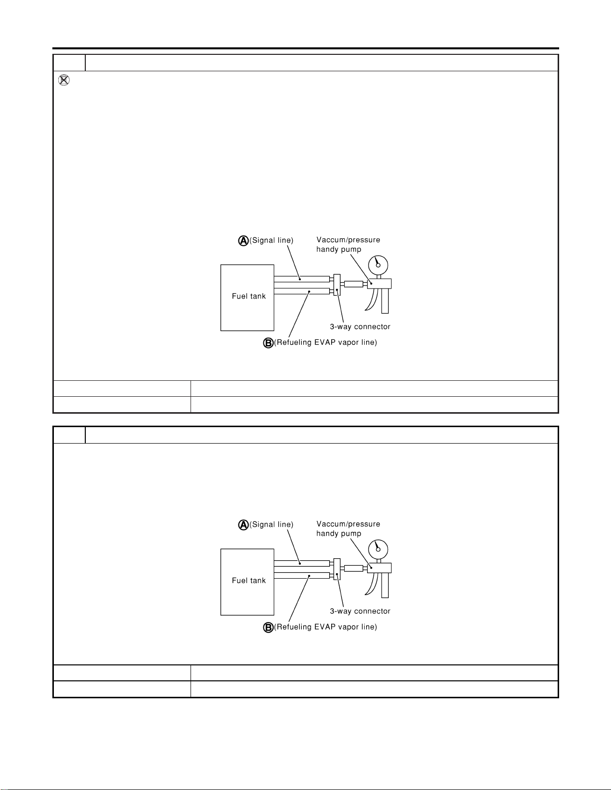
7 CHECK REFUELING EVAP VAPOR CUT VALVE
Without CONSULT-II
1. Remove fuel tank. Refer to FE-4, “FUEL SYSTEM”.
2. Drain fuel from the tank as follows:
a. Remove fuel gauge retainer.
b. Drain fuel from the tank using a hand pump into a fuel container.
3. Check refueling EVAP vapor cut valve for being stuck to close as follows.
Blow air into the refueling EVAP vapor cut valve (from hose end B), and check that the air flows freely into the tank.
4. Check EVAP vapor cut valve for being stuck to open as follows.
a. Connect vacuum pump to hose ends A and B using a suitable 3-way connector.
b. Remove fuel gauge retainer with fuel gauge unit.
Always replace O-ring with new one.
c. Put fuel tank upside down.
d. Apply vacuum pressure to both hose ends A and B [−13.3 kPa (−100 mmHg, −3.94 inHg)] with fuel gauge retainer
remaining open and check that the pressure is applicable.
SEF968X
OK or NG
OK © GO TO 8.
NG © Replace refueling EVAP vapor cut valve with fuel tank.
8 CHECK REFUELING CONTROL VALVE
1. Remove fuel filler cap.
2. Check air continuity between hose ends A and B.
Blow air into the hose end B. Air should flow freely into the fuel tank.
3. Blow air into hose end A and check there is no leakage.
4. Apply pressure to both hose ends A and B [20 kPa (150 mmHg, 5.91 inHg)] using a pressure pump and a suitable
3-way connector. Check that there is no leakage.
SEF968X
OK or NG
OK © INSPECTION END
NG © Replace refueling control valve with fuel tank.
ENGINE AND EMISSION BASIC CONTROL SYSTEM DESCRIPTION
On Board Refueling Vapor Recovery (ORVR) (Cont’d)
EC-46
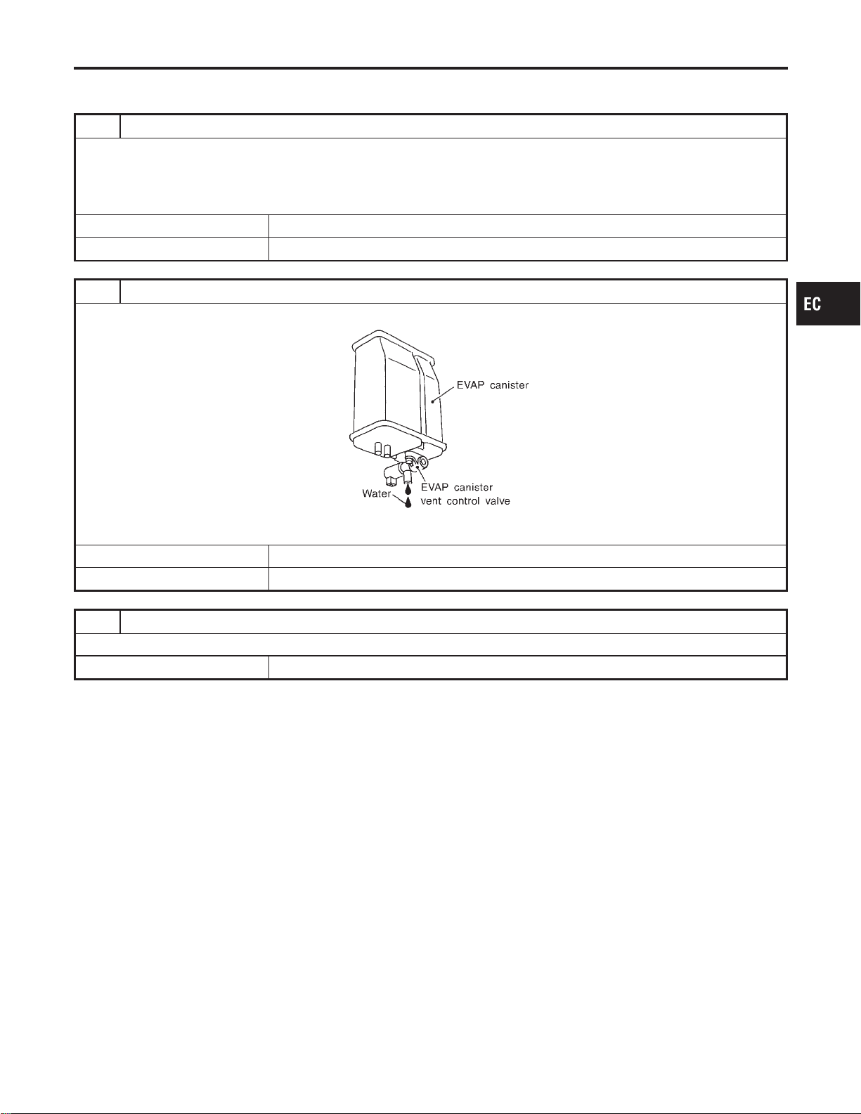
Symptom: Cannot Refuel/Fuel Odor From The Fuel Filler Opening Is Strong While
Refueling.
NFEC0744S0202
1 CHECK EVAP CANISTER
1. Remove EVAP canister with EVAP canister vent control valve attached.
2. Weigh the EVAP canister with EVAP canister vent control valve attached.
The weight should be less than 1.8 kg (4.0 lb).
OK or NG
OK © GO TO 2.
NG © GO TO 3.
2 CHECK IF EVAP CANISTER SATURATED WITH WATER
Does water drain from the EVAP canister?
SEF596U
YesorNo
Yes © GO TO 3.
No © GO TO 6.
3 REPLACE EVAP CANISTER
Replace EVAP canister with a new one.
© GO TO 4.
GI
MA
EM
LC
FE
CL
MT
AT
AX
SU
BR
ST
RS
BT
HA
SC
EL
IDX
ENGINE AND EMISSION BASIC CONTROL SYSTEM DESCRIPTION
On Board Refueling Vapor Recovery (ORVR) (Cont’d)
EC-47
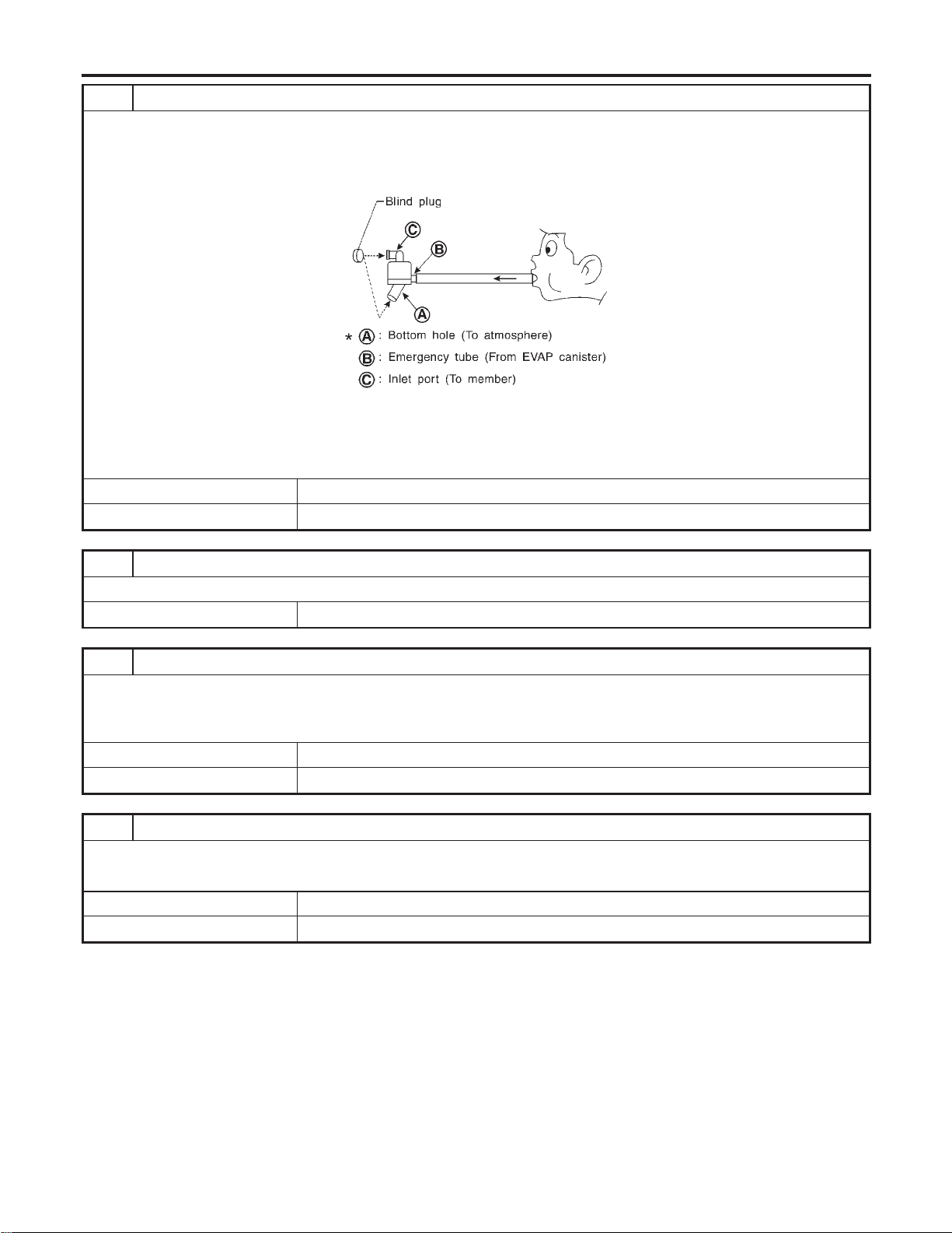
4 CHECK WATER SEPARATOR
1. Check visually for insect nests in the water separator air inlet.
2. Check visually for cracks or flaws in the appearance.
3. Check visually for cracks or flaws in the hose.
4. Check that A and C are not clogged by blowing air into B with A, and then C plugged.
SEF829T
5. In case of NG in items2-4,replace the parts.
NOTE:
I Do not disassemble water separator.
OK or NG
OK © GO TO 5.
NG © Replace water separator.
5 DETECT MALFUNCTIONING PART
Check the EVAP hose between EVAP canister and water separator for clogging or poor connection.
© Repair or replace EVAP hose.
6 CHECK VENT HOSES AND VENT TUBES
Check hoses and tubes between EVAP canister and refueling control valve for clogging, kink, looseness and improper
connection.
OK or NG
OK © GO TO 7.
NG © Repair or replace hoses and tubes.
7 CHECK FILLER NECK TUBE
Check signal line and recirculation line for clogging, dents and cracks.
OK or NG
OK © GO TO 8.
NG © Replace filler neck tube.
ENGINE AND EMISSION BASIC CONTROL SYSTEM DESCRIPTION
On Board Refueling Vapor Recovery (ORVR) (Cont’d)
EC-48
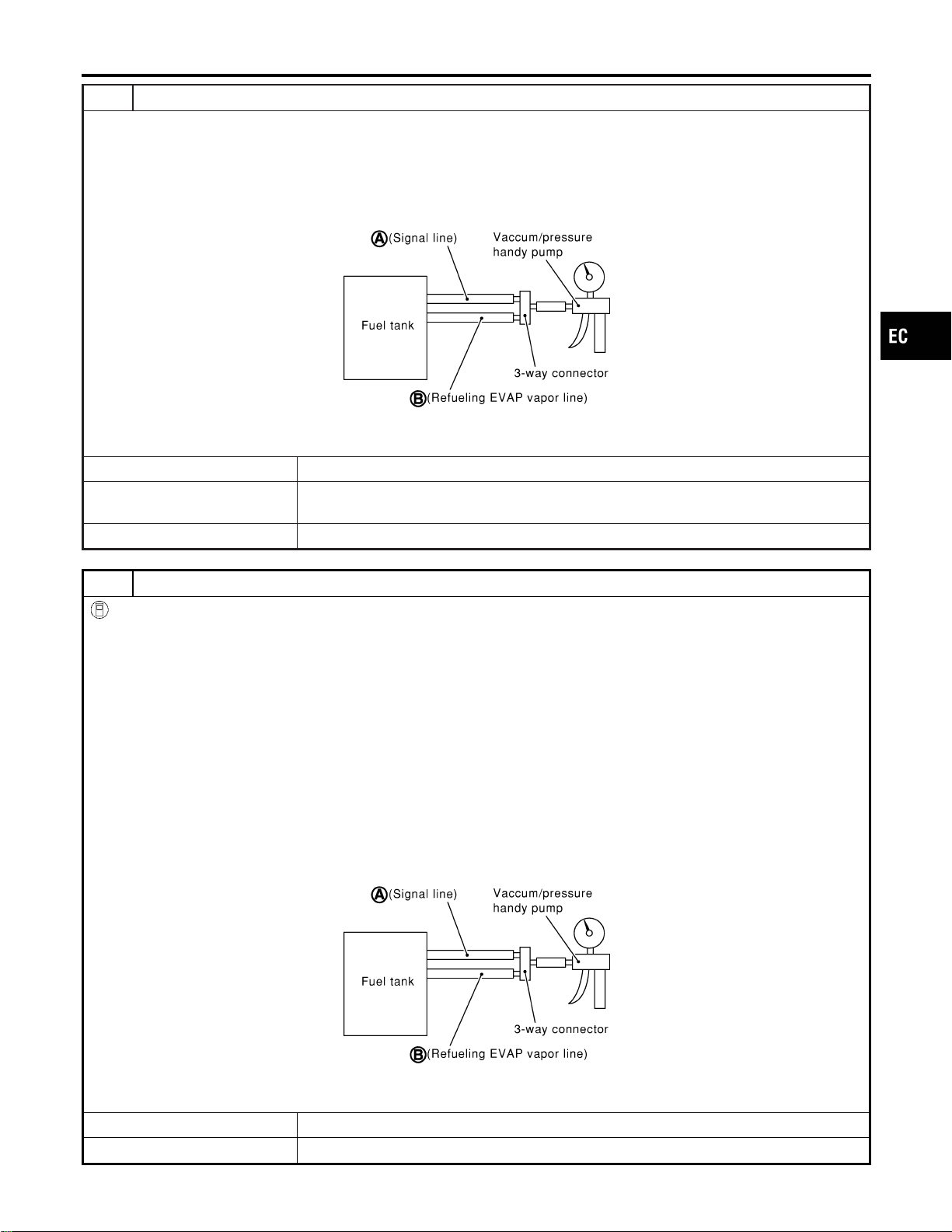
8 CHECK REFUELING CONTROL VALVE
1. Remove fuel filler cap.
2. Check air continuity between hose ends A and B.
Blow air into the hose end B. Air should flow freely into the fuel tank.
3. Blow air into hose end A and check there is no leakage.
4. Apply pressure to both hose ends A and B [20 kPa (150 mmHg, 5.91 inHg)] using a pressure pump and a suitable
3-way connector. Check that there is no leakage.
SEF968X
OK or NG
OK (With CONSULT-II) © GO TO 9.
OK (Without CONSULT-
II)
© GO TO 10.
NG © Replace refueling control valve with fuel tank.
9 CHECK REFUELING EVAP VAPOR CUT VALVE
With CONSULT-II
1. Remove fuel tank. Refer to FE-4, “FUEL SYSTEM”.
2. Drain fuel from the tank as follows:
a. Remove fuel feed hose located on the fuel gauge retainer.
b. Connect a spare fuel hose, one side to fuel gauge retainer where the hose was removed and the other side to a fuel
container.
c. Drain fuel using “FUEL PUMP RELAY” in “ACTIVE TEST” mode with CONSULT-II.
3. Check refueling EVAP vapor cut valve for being stuck to close as follows.
Blow air into the refueling EVAP vapor cut valve (from hose end B), and check that the air flows freely into the tank.
4. Check EVAP vapor cut valve for being stuck to open as follows.
a. Connect vacuum pump to hose ends A and B using a suitable 3-way connector.
b. Remove fuel gauge retainer with fuel gauge unit.
Always replace O-ring with new one.
c. Put fuel tank upside down.
d. Apply vacuum pressure to both hose ends A and B [−13.3 kPa (−100 mmHg, −3.94 inHg)] with fuel gauge retainer
remaining open and check that the pressure is applicable.
SEF968X
OK or NG
OK © GO TO 11.
NG © Replace refueling EVAP vapor cut valve with fuel tank.
GI
MA
EM
LC
FE
CL
MT
AT
AX
SU
BR
ST
RS
BT
HA
SC
EL
IDX
ENGINE AND EMISSION BASIC CONTROL SYSTEM DESCRIPTION
On Board Refueling Vapor Recovery (ORVR) (Cont’d)
EC-49

10 CHECK REFUELING EVAP VAPOR CUT VALVE
Without CONSULT-II
1. Remove fuel tank. Refer to FE-4, “FUEL SYSTEM”.
2. Drain fuel from the tank as follows:
a. Remove fuel gauge retainer.
b. Drain fuel from the tank using a hand pump into a fuel container.
3. Check refueling EVAP vapor cut valve for being stuck to close as follows.
Blow air into the refueling EVAP vapor cut valve (from hose end B), and check that the air flows freely into the tank.
4. Check EVAP vapor cut valve for being stuck to open as follows.
a. Connect vacuum pump to hose ends A and B using a suitable 3-way connector.
b. Remove fuel gauge retainer with fuel gauge unit.
Always replace O-ring with new one.
c. Put fuel tank upside down.
d. Apply vacuum pressure to both hose ends A and B [−13.3 kPa (−100 mmHg, −3.94 inHg)] with fuel gauge retainer
remaining open and check that the pressure is applicable.
SEF968X
OK or NG
OK © GO TO 11.
NG © Replace refueling EVAP vapor cut valve with fuel tank.
11 CHECK FUEL FILLER TUBE
Check filler neck tube and hose connected to the fuel tank for clogging, dents and cracks.
OK or NG
OK © GO TO 12.
NG © Replace fuel filler tube.
12 CHECK ONE-WAY FUEL VALVE-I
Check one-way valve for clogging.
OK or NG
OK © GO TO 13.
NG © Repair or replace one-way fuel valve with fuel tank.
ENGINE AND EMISSION BASIC CONTROL SYSTEM DESCRIPTION
On Board Refueling Vapor Recovery (ORVR) (Cont’d)
EC-50
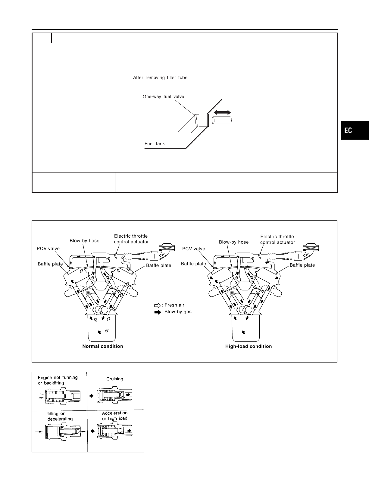
13 CHECK ONE-WAY FUEL VALVE-II
1. Make sure that fuel is drained from the tank.
2. Remove fuel filler tube and hose.
3. Check one-way fuel valve for operation as follows.
When a stick is inserted, the valve should open, when removing stick it should close.
SEF665U
Do not drop any material into the tank.
OK or NG
OK © INSPECTION END
NG © Replace fuel filler tube or replace one-way fuel valve with fuel tank.
Positive Crankcase Ventilation
DESCRIPTION
NFEC0021
SEC921C
SEF559A
This system returns blow-by gas to the intake manifold.
The positive crankcase ventilation (PCV) valve is provided to con-
duct crankcase blow-by gas to the intake manifold.
During partial throttle operation of the engine, the intake manifold
sucks the blow-by gas through the PCV valve.
Normally, the capacity of the valve is sufficient to handle any
blow-by and a small amount of ventilating air.
The ventilating air is then drawn from the air inlet tubes into the
crankcase. In this process the air passes through the hose con-
necting air inlet tubes to rocker cover.
Under full-throttle condition, the manifold vacuum is insufficient to
draw the blow-by flow through the valve. The flow goes through the
GI
MA
EM
LC
FE
CL
MT
AT
AX
SU
BR
ST
RS
BT
HA
SC
EL
IDX
ENGINE AND EMISSION BASIC CONTROL SYSTEM DESCRIPTION
On Board Refueling Vapor Recovery (ORVR) (Cont’d)
EC-51
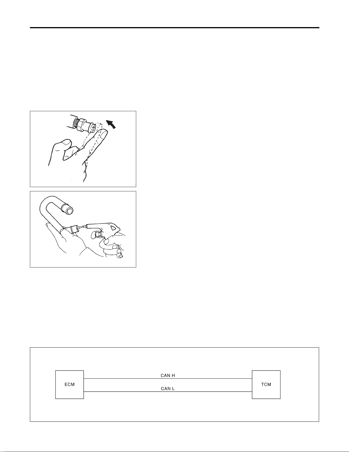
hose connection in the reverse direction.
On vehicles with an excessively high blow-by, the valve does not
meet the requirement. This is because some of the flow will go
through the hose connection to the air inlet tubes under all
conditions.
SEC137A
INSPECTION
NFEC0022
PCV (Positive Crankcase Ventilation) Valve
NFEC0022S01
With engine running at idle, remove PCV valve from rocker cover.
A properly working valve makes a hissing noise as air passes
through it. A strong vacuum should be felt immediately when a fin-
ger is placed over valve inlet.
ET277
PCV Valve Ventilation Hose
NFEC0022S02
1. Check hoses and hose connections for leaks.
2. Disconnect all hoses and clean with compressed air. If any
hose cannot be freed of obstructions, replace.
CAN Communication
NFEC1183
SYSTEM DESCRIPTION
NFEC1183S01
CAN (Controller Area Network) is a serial communication line for real time application. It is an on-vehicle mul-
tiplex communication line with high data communication speed and excellent error detection ability. Many
electronic control units are equipped onto a vehicle, and each control unit shares information and links with
other control units during operation (not independent). In CAN communication, control units are connected with
2 communication lines (CAN H line, CAN L line) allowing a high rate of information transmission with less wir-
ing. Each control unit transmits/receives data but selectively reads required data only.
For A/T Models
NFEC1183S0101
System Diagram
SEL448Y
ENGINE AND EMISSION BASIC CONTROL SYSTEM DESCRIPTION
Positive Crankcase Ventilation (Cont’d)
EC-52
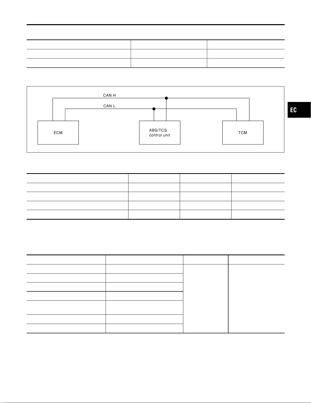
Input/Output Signal Chart
T: Transmit R: Receive
Signals ECM TCM
Accelerator pedal position signal T R
Output shaft revolution signal R T
For TCS Models
NFEC1183S0102
System Diagram
SEL449Y
INPUT/OUTPUT SIGNAL CHART
NFEC1183S02
T: Transmit R: Receive
Signals ECM ABS/TCS control unit TCM
Accelerator pedal position signal T R R
Output shaft revolution signal R T
TCS self-diagnostic signal R T
ABS self-diagnostic signal R T
Automatic Speed Control Device (ASCD)
System
DESCRIPTION
NFEC1184
Input/Output Signal Chart
NFEC1184S01
Sensor Input signal to ECM ECM function Actuator
ASCD brake switch Brake pedal operation
ASCD vehicle speed
control
Electric throttle control
actuator
Stop lamp switch Brake pedal operation
ASCD clutch switch (MT models) Clutch pedal operation
ASCD steering switch ASCD steering switch operation
Park/Neutral position (PNP) switch
(AT models)
Gear position
Combination meter Vehicle speed
TCM Power train revolution
Basic ASCD System
NFEC1184S02
Refer to Owner’s Manual for ASCD operating instructions.
Automatic Speed Control Device (ASCD) allows a driver to keep vehicle at predetermined constant speed
without depressing accelerator pedal. Driver can set vehicle speed in advance between approximately 40 km/h
(25 MPH) and 144 km/h (89 MPH).
GI
MA
EM
LC
FE
CL
MT
AT
AX
SU
BR
ST
RS
BT
HA
SC
EL
IDX
ENGINE AND EMISSION BASIC CONTROL SYSTEM DESCRIPTION
CAN Communication (Cont’d)
EC-53

ECM controls throttle valve operating angle of electric throttle control actuator to regulate engine speed.
Operation status of ASCD is indicated by CRUISE indicator and SET indicator in combination meter.
If any malfunction occurs in ASCD system, it automatically deactivates control.
Set Operation
NFEC1184S03
Press ASCD CRUISE switch (Main switch). (Then CRUISE indicator in combination meter illuminates.)
When vehicle speed reaches a desired speed between approximately 40 km/h (25 MPH) and 144 km/h (89
MPH), press SET switch. (Then SET indicator in combination meter illuminates.)
Accel Operation
NFEC1184S04
If the RESUME/ACCEL switch is depressed during cruise control driving, increase the vehicle speed until the
switch is released or vehicle speed reaches maximum speed controlled by the system.
And then ASCD will keep the new set speed.
Cancel Operation
NFEC1184S05
When any of following conditions exist, cruise operation will be canceled.
I CANCEL switch is depressed.
I Brake pedal is depressed.
I Clutch pedal is depressed (M/T models).
I A/T selector lever is shifted to P or N position (A/T models).
If MAIN switch is turned to OFF while ASCD is activated, all of ASCD operations will be canceled and vehicle
speed memory will be erased.
Coast Operation
NFEC1184S06
When the SET/COAST switch is depressed during cruise control driving, decrease vehicle set speed until the
switch is released. And then ASCD will keep the new set speed.
Resume Operation
NFEC1184S07
When the RESUME/ACCEL switch is depressed after cancel operation other than depressing MAIN switch is
performed, vehicle speed will return to last set speed. To resume vehicle set speed, vehicle condition must
meet following conditions.
I Brake pedal is released.
I Clutch pedal is released (M/T models).
I A/T selector lever is in other than P and N position (A/T models).
I Vehicle speed is greater than 40 km/h (25 MPH) and 144 km/h (89 MPH).
ENGINE AND EMISSION BASIC CONTROL SYSTEM DESCRIPTION
Automatic Speed Control Device (ASCD) System (Cont’d)
EC-54
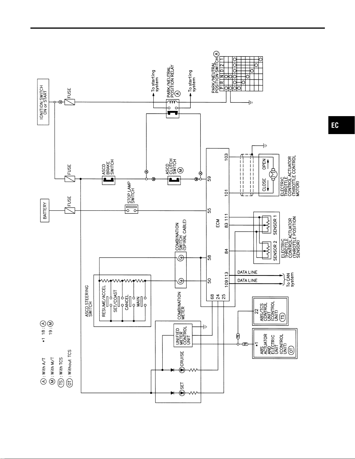
SYSTEM DIAGRAM
NFEC1185
MEC921D
GI
MA
EM
LC
FE
CL
MT
AT
AX
SU
BR
ST
RS
BT
HA
SC
EL
IDX
ENGINE AND EMISSION BASIC CONTROL SYSTEM DESCRIPTION
Automatic Speed Control Device (ASCD) System (Cont’d)
EC-55
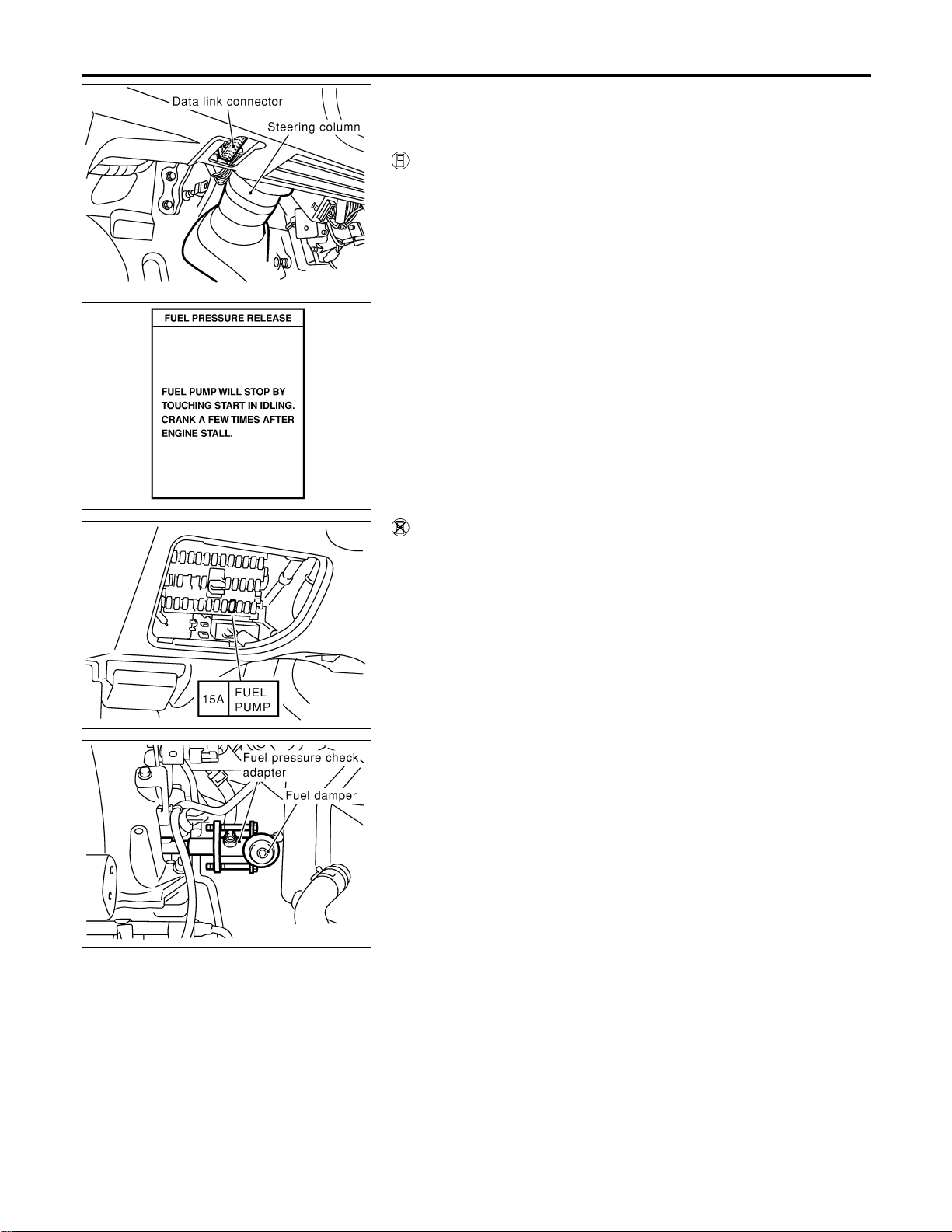
SEF289X
SEF214Y
Fuel Pressure Release
NFEC0023
Before disconnecting fuel line, release fuel pressure from fuel
line to eliminate danger.
WITH CONSULT-II
NFEC0023S01
1. Turn ignition switch “ON”.
2. Perform “FUEL PRESSURE RELEASE” in “WORK SUP-
PORT” mode with CONSULT-II.
3. Start engine.
4. After engine stalls, crank it two or three times to release all fuel
pressure.
5. Turn ignition switch “OFF”.
SEF997Z
WITHOUT CONSULT-II
NFEC0023S02
1. Remove fuel pump fuse located in fuse box.
2. Start engine.
3. After engine stalls, crank it two or three times to release all fuel
pressure.
4. Turn ignition switch “OFF”.
5. Reinstall fuel pump fuse after servicing fuel system.
SEC997C
Fuel Pressure Check
NFEC0024
I When reconnecting fuel line, always use new clamps.
I Make sure that clamp screw does not contact adjacent
parts.
I Use a torque driver to tighten clamps.
I Use Pressure Gauge to check fuel pressure.
I Do not perform fuel pressure check with system operat-
ing. Fuel pressure gauge may indicate false readings.
1. Release fuel pressure to zero.
2. Disconnect fuel tube joint between fuel damper and injector
tube and set fuel pressure check adapter (J44321).
BASIC SERVICE PROCEDURE
Fuel Pressure Release
EC-56
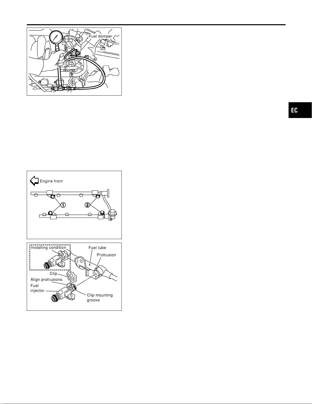
SEC998C
3. Install pressure gauge to the fuel pressure check adapter as
shown in the figure.
4. Start engine and check for fuel leakage.
5. Read the indication of fuel pressure gauge.
At idling: Approximately 350 kPa (3.57 kg/cm
2
, 51 psi)
6. If results are unsatisfactory, go to next step.
7. Check the following.
I Fuel hoses and fuel tubes for clogging
I Fuel filter for clogging
I Fuel pump
I Fuel pressure regulator for clogging
If OK, replace fuel pressure regulator.
If NG, repair or replace.
SEC030D
SEF703X
Injector
REMOVAL AND INSTALLATION
NFEC0026
1. Release fuel pressure to zero.
2. Remove intake manifold collector. Refer to EM-21, “TIMING
CHAIN”.
3. Remove fuel tube assemblies in numerical sequence as
shown in the figure at left.
4. Expand and remove clips securing fuel injectors.
5. Extract fuel injectors straight from fuel tubes.
I Be careful not to damage injector nozzles during removal.
I Do not bump or drop fuel injectors.
6. Carefully install O-rings.
I Lubricate O-rings with a smear of engine oil.
I Be careful not to damage O-rings with service tools, fin-
ger nails or clips. Do not expand or twist O-rings.
I Discard old clips; replace with new ones.
7. Position clips in grooves on fuel injectors.
I Make sure that protrusions of fuel injectors are aligned
with cutouts of clips after installation.
GI
MA
EM
LC
FE
CL
MT
AT
AX
SU
BR
ST
RS
BT
HA
SC
EL
IDX
BASIC SERVICE PROCEDURE
Fuel Pressure Check (Cont’d)
EC-57
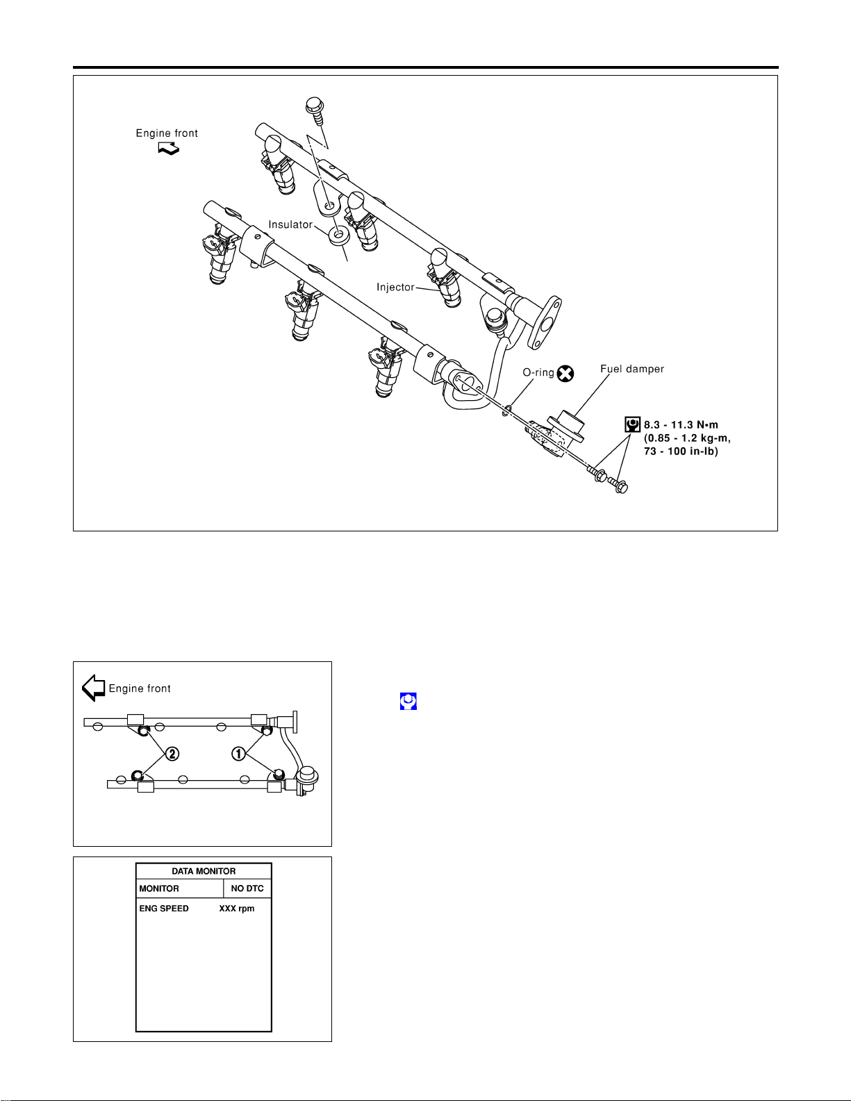
SEC031D
8. Align protrusions of fuel tubes with those of fuel injectors.
Insert fuel injectors straight into fuel tubes.
9. After properly inserting fuel injectors, check to make sure that
fuel tube protrusions are engaged with those of fuel injectors,
and that flanges of fuel tubes are engaged with clips.
SEC999C
10. Tighten fuel tube assembly mounting nuts in numerical
sequence (indicated in the figure at left) and in two stages.
: Tightening torque N·m (kg-m, ft-lb)
1st stage:
9.3 - 10.8 (1.0 - 1.1, 6.9 - 7.9)
2nd stage:
20.6 - 26.5 (2.1 - 2.7, 16 - 19)
11. Install all parts removed in reverse order of removal.
CAUTION:
After properly connecting fuel tube assembly to injector and
fuel hose, check connection for fuel leakage.
SEF058Y
How to Check Idle Speed and Ignition Timing
NFEC1422
IDLE SPEED
NFEC1422S01
I Using CONSULT-II
Check idle speed in “DATA MONITOR” mode with CONSULT-II.
BASIC SERVICE PROCEDURE
Injector (Cont’d)
EC-58
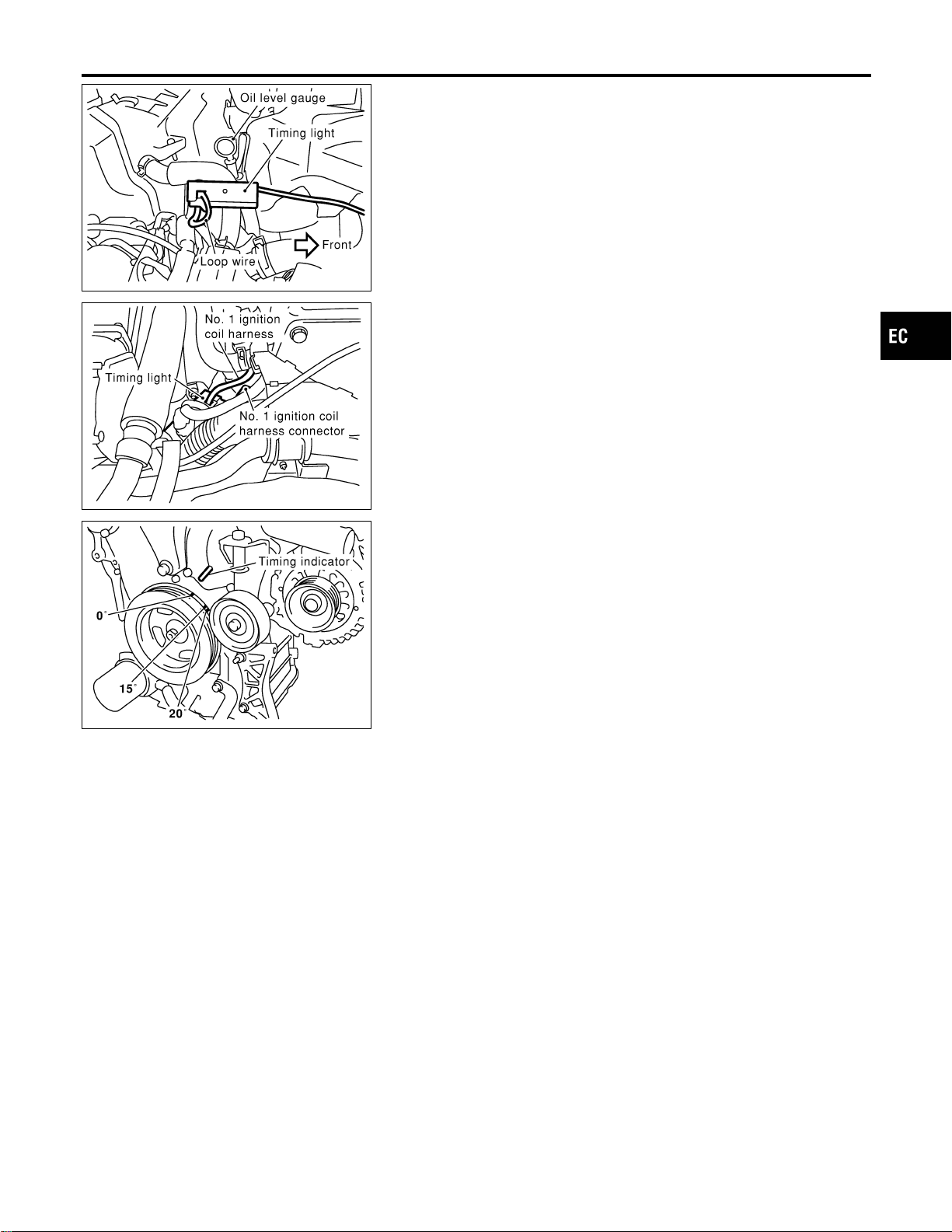
SEC001D
IGNITION TIMING
NFEC1422S02
Any of following two methods may be used.
I Method A
a) Attach timing light to loop wire as shown.
b) Check ignition timing.
SEC002D
I Method B
a) Attach timing light to No. 1 ignition coil harness as shown.
SEC004D
b) Check ignition timing.
Idle Speed/Ignition Timing/Idle Mixture Ratio
Adjustment
NFEC0028
PREPARATION
NFEC0028S01
1) Make sure that the following parts are in good order.
I Battery
I Ignition system
I Engine oil and coolant levels
I Fuses
I ECM harness connector
I Vacuum hoses
I Air intake system
(Oil filler cap, oil level gauge, etc.)
I Fuel pressure
I Engine compression
I Throttle valve
I Evaporative emission system
2) On air conditioner equipped models, checks should be carried out while the air conditioner is “OFF”.
3) On automatic transmission equipped models, when checking idle rpm, ignition timing and mixture ratio,
checks should be carried out while shift lever is in “N” position.
4) When measuring “CO” percentage, insert probe more than 40 cm (15.7 in) into tail pipe.
5) Turn off headlamps, heater blower, rear defogger.
GI
MA
EM
LC
FE
CL
MT
AT
AX
SU
BR
ST
RS
BT
HA
SC
EL
IDX
BASIC SERVICE PROCEDURE
How to Check Idle Speed and Ignition Timing (Cont’d)
EC-59

6) Keep front wheels pointed straight ahead.
7) Make the check after the cooling fan has stopped.
BASIC SERVICE PROCEDURE
Idle Speed/Ignition Timing/Idle Mixture Ratio Adjustment (Cont’d)
EC-60
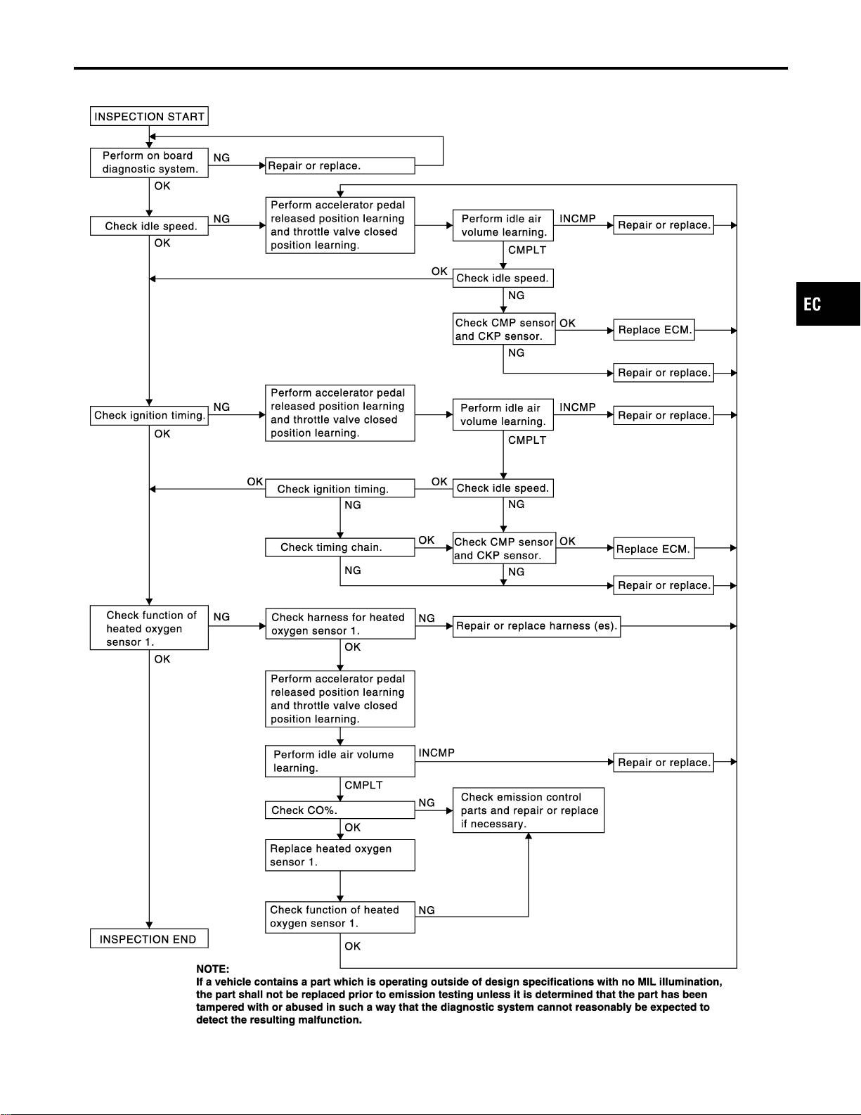
Overall Inspection Sequence
NFEC0028S0101
SEC154D
GI
MA
EM
LC
FE
CL
MT
AT
AX
SU
BR
ST
RS
BT
HA
SC
EL
IDX
BASIC SERVICE PROCEDURE
Idle Speed/Ignition Timing/Idle Mixture Ratio Adjustment (Cont’d)
EC-61
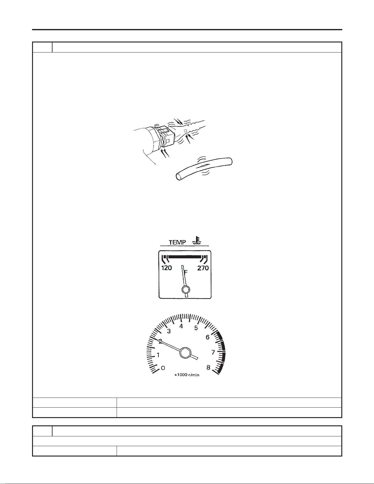
INSPECTION PROCEDURE
=NFEC0028S02
1 INSPECTION START
1. Check service records for any recent repairs that may indicate a related problem, or a current need for scheduled
maintenance.
2. Open engine hood and check the following:
– Harness connectors for improper connections
– Wiring harness for improper connections, pinches and cut
– Vacuum hoses for splits, kinks and improper connections
– Hoses and ducts for leaks
– Air cleaner clogging
– Gasket
SEF983U
3. Confirm that electrical or mechanical loads are not applied.
– Headlamp switch is OFF.
– Air conditioner switch is OFF.
– Rear window defogger switch is OFF.
– Steering wheel is in the straight-ahead position, etc.
4. Start engine and warm it up until engine coolant temperature indicator points the middle of gauge.
Ensure engine stays below 1,000 rpm.
SEF976U
5. Run engine at about 2,000 rpm for about 2 minutes under no-load.
SEF977U
6. Make sure that no DTC is displayed with CONSULT-II or GST.
OK or NG
OK © GO TO 3.
NG © GO TO 2.
2 REPAIR OR REPLACE
Repair or replace components as necessary according to corresponding “Diagnostic Procedure”.
© GO TO 3.
BASIC SERVICE PROCEDURE
Idle Speed/Ignition Timing/Idle Mixture Ratio Adjustment (Cont’d)
EC-62
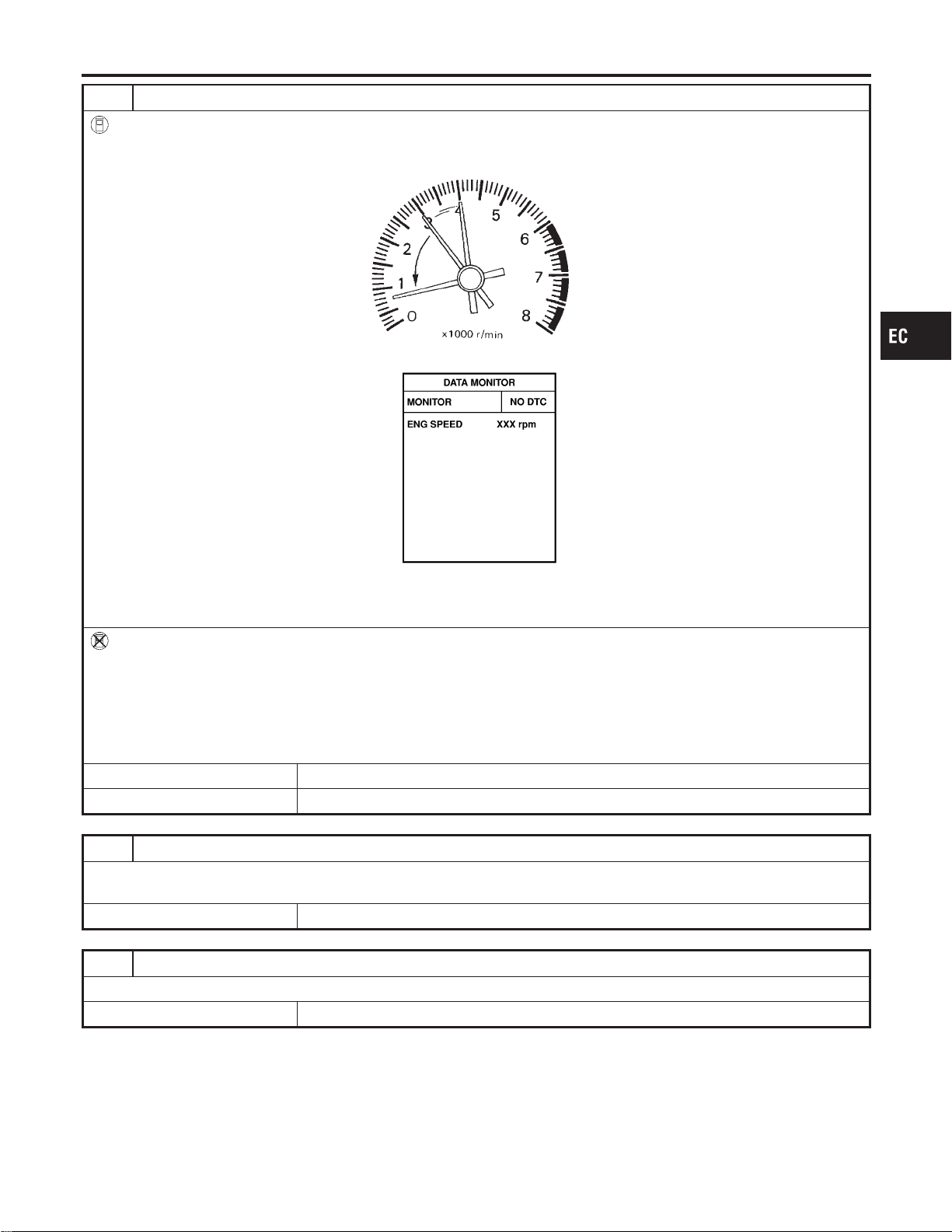
3 CHECK TARGET IDLE SPEED
With CONSULT-II
1. Run engine at about 2,000 rpm for about 2 minutes under no-load.
2. Rev engine (2,000 to 3,000 rpm) two or three times under no-load, then run engine at idle speed for about 1 minute.
SEF978U
3. Read idle speed in “DATA MONITOR” mode with CONSULT-II.
SEF058Y
M/T: 625±50 rpm
A/T: 675±50 rpm (in “P” or “N” position)
Without CONSULT-II
1. Run engine at about 2,000 rpm for about 2 minutes under no-load.
2. Rev engine (2,000 to 3,000 rpm) two or three times under no-load, then run engine at idle speed for about 1 minute.
3. Check idle speed.
M/T: 625±50 rpm
A/T: 675±50 rpm (in “P” or “N” position)
OK or NG
OK © GO TO 9.
NG © GO TO 4.
4 PERFORM ACCELERATOR PEDAL RELEASED POSITION LEARNING
1. Stop engine.
2. Perform “Accelerator Pedal Released Position Learning”, EC-71.
© GO TO 5.
5 PERFORM THROTTLE VALVE CLOSED POSITION LEARNING
Perform “Throttle Valve Closed Position Learning”, EC-71.
© GO TO 6.
GI
MA
EM
LC
FE
CL
MT
AT
AX
SU
BR
ST
RS
BT
HA
SC
EL
IDX
BASIC SERVICE PROCEDURE
Idle Speed/Ignition Timing/Idle Mixture Ratio Adjustment (Cont’d)
EC-63
6 PERFORM IDLE AIR VOLUME LEARNING
Perform “Idle Air Volume Learning”, EC-71.
Which is the result CMPLT or INCMP?
CMPLT or INCMP
CMPLT © GO TO 7.
INCMP © 1. Follow the construction of “Idle Air Volume Learning”.
2. GO TO 4.
7 CHECK TARGET IDLE SPEED AGAIN
With CONSULT-II
1. Start engine and warm it up to normal operating temperature.
2. Read idle speed in “DATA MONITOR” mode with CONSULT-II.
M/T: 625±50 rpm
A/T: 675±50 rpm (in “P” or “N” position)
Without CONSULT-II
1. Start engine and warm it up to normal operating temperature.
2. Check idle speed.
M/T: 625±50 rpm
A/T: 675±50 rpm (in “P” or “N” position)
OK or NG
OK © GO TO 10.
NG © GO TO 8.
8 DETECT MALFUNCTIONING PART
Check the following.
I Check camshaft position sensor (PHASE) and circuit. Refer to ”DTC P0340, P0345 CMP SENSOR (PHASE)”, EC-337.
I Check crankshaft position sensor (POS) and circuit. Refer to “DTC P0335 CKP SENSOR (POS)”, EC-330.
OK or NG
OK © GO TO 9.
NG © 1. Repair or replace.
2. GO TO 4.
9 CHECK ECM FUNCTION
1. Substitute another known-good ECM to check ECM function. (ECM may be the cause of a problem, but this is the
rarely the case.)
2. Perform initialization of NVIS (NATS) system and registration of NVIS (NATS) ignition key IDs. Refer to NVIS (NISSAN
VEHICLE IMMOBILIZER SYSTEM — NATS)”, EC-92.
© GO TO 4.
10 CHECK IGNITION TIMING
1. Run engine at idle.
2. Check ignition timing with a timing light.
M/T: 15°±5° BTDC
A/T: 15°±5° BTDC (in “P” or “N” position)
OK or NG
OK (With CONSULT-II) © GO TO 19.
OK (Without CONSULT-
II)
© GO TO 20.
NG © GO TO 11.
BASIC SERVICE PROCEDURE
Idle Speed/Ignition Timing/Idle Mixture Ratio Adjustment (Cont’d)
EC-64
11 PERFORM ACCELERATOR PEDAL RELEASED POSITION LEARNING
1. Stop engine.
2. Perform “Accelerator Pedal Released Position Learning”, EC-71.
© GO TO 12.
12 PERFORM THROTTLE VALVE CLOSED POSITION LEARNING
Perform “Throttle Valve Closed Position Learning”, EC-71.
© GO TO 13.
13 PERFORM IDLE AIR VOLUME LEARNING
Perform “Idle Air Volume Learning”, EC-71.
Which is the result CMPLT or INCMP?
CMPLT or INCMP
CMPLT © GO TO 14.
INCMP © 1. Follow the construction of “Idle Air Volume Learning”.
2. GO TO 4.
14 CHECK TARGET IDLE SPEED AGAIN
With CONSULT-II
1. Start engine and warm it up to normal operating temperature.
2. Read idle speed in “DATA MONITOR” mode with CONSULT-II.
M/T: 625±50 rpm
A/T: 675±50 rpm (in “P” or “N” position)
Without CONSULT-II
1. Start engine and warm it up to normal operating temperature.
2. Check idle speed.
M/T: 625±50 rpm
A/T: 675±50 rpm (in “P” or “N” position)
OK or NG
OK © GO TO 15.
NG © GO TO 17.
15 CHECK IGNITION TIMING AGAIN
1. Run engine at idle.
2. Check ignition timing with a timing light.
M/T: 15°±5° BTDC
A/T: 15°±5° BTDC (in “P” or “N” position)
OK or NG
OK (With CONSULT-II) © GO TO 19.
OK (Without CONSULT-
II)
© GO TO 20.
NG © GO TO 16.
GI
MA
EM
LC
FE
CL
MT
AT
AX
SU
BR
ST
RS
BT
HA
SC
EL
IDX
BASIC SERVICE PROCEDURE
Idle Speed/Ignition Timing/Idle Mixture Ratio Adjustment (Cont’d)
EC-65
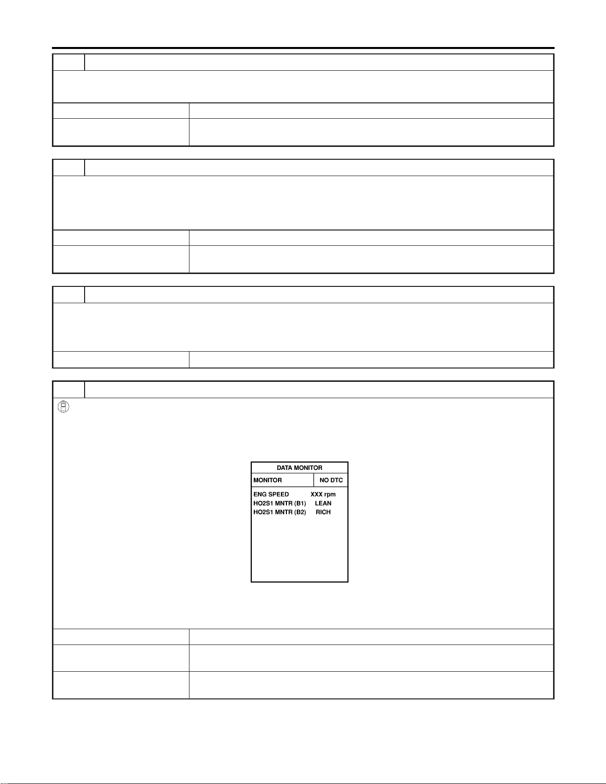
16 CHECK TIMING CHAIN INSTALLATION
Check timing chain installation. Refer to EM-21, “TIMING CHAIN”.
OK or NG
OK © GO TO 17.
NG © 1. Repair the timing chain installation.
2. GO TO 4.
17 DETECT MALFUNCTIONING PART
Check the following.
I Check camshaft position sensor (PHASE) and circuit. Refer to “DTC P0340, P0345 CMP SENSOR (PHASE)”, EC-337.
I Check crankshaft position sensor (POS) and circuit. Refer to “DTC P0335 CKP SENSOR (POS)”, EC-330.
OK or NG
OK © GO TO 18.
NG © 1. Repair or replace.
2. GO TO 4.
18 CHECK ECM FUNCTION
1. Substitute another known-good ECM to check ECM function. (ECM may be the cause of a problem, but this is the
rarely the case.)
2. Perform initialization of NVIS (NATS) system and registration of NVIS (NATS) ignition key IDs. Refer to “NVIS (NISSAN
VEHICLE IMMOBILIZER SYSTEM — NATS)”, EC-92.
© GO TO 4.
19 CHECK HEATED OXYGEN SENSOR 1 (BANK 1) SIGNAL
With CONSULT-II
1. Run engine at about 2,000 rpm for about 2 minutes under no-load.
2. See “HO2S1 MNTR (B1)” in “DATA MONITOR” mode.
3. Running engine at 2,000 rpm under no-load (The engine is warmed up to normal operating temperature.), check that
the monitor fluctuates between LEAN and RICH more than 5 times during 10 seconds.
PBIB0120E
1 time: RICH → LEAN → RICH
2 times: RICH → LEAN → RICH → LEAN → RICH
OK or NG
OK © GO TO 21.
NG (Monitor does not
fluctuate.)
© GO TO 23.
NG (Monitor fluctuates
less than 5 times.)
© GO TO 30.
BASIC SERVICE PROCEDURE
Idle Speed/Ignition Timing/Idle Mixture Ratio Adjustment (Cont’d)
EC-66
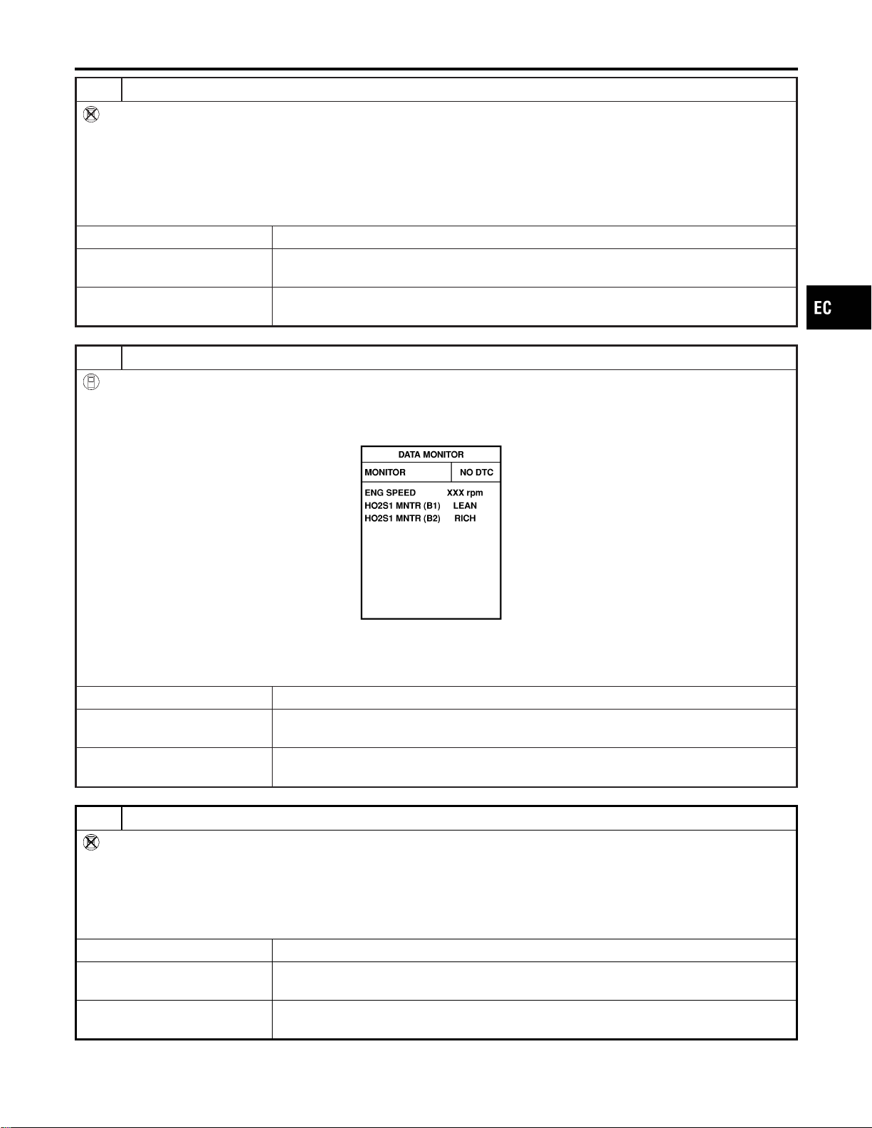
20 CHECK HEATED OXYGEN SENSOR 1 (BANK 1) SIGNAL
Without CONSULT-II
1. Stop engine and set ECM to Self-diagnostic mode II (Heated oxygen sensor 1 monitor). Refer to “HOW TO SWITCH
DIAGNOSTIC TEST MODE”, EC-94.
2. Start engine and run it at about 2,000 rpm for about 2 minutes under no-load.
3. Running engine at 2,000 rpm under no-load (The engine is warmed up to normal operating temperature.), check that
the MIL comes on more than 5 times during 10 seconds.
OK or NG
OK © GO TO 22.
NG (MIL does not come
on)
© GO TO 23.
NG (MIL comes on less
than 5 times)
© GO TO 30.
21 CHECK HEATED OXYGEN SENSOR 1 (BANK 2) SIGNAL
With CONSULT-II
1. See “HO2S1 MNTR (B2)” in “DATA MONITOR” mode.
2. Running engine at 2,000 rpm under no-load (The engine is warmed up to normal operating temperature.), check that
the monitor fluctuates between LEAN and RICH more than 5 times during 10 seconds.
PBIB0120E
1 time: RICH → LEAN → RICH
2 times: RICH → LEAN → RICH → LEAN → RICH
OK or NG
OK © INSPECTION END
NG (Monitor does not
fluctuate.)
© GO TO 24.
NG (Monitor fluctuates
less than 5 times.)
© GO TO 31.
22 CHECK HEATED OXYGEN SENSOR 1 (BANK 2) SIGNAL
Without CONSULT-II
1. Switch the monitored sensor from bank 1 to bank 2. Refer to “How to Switch Monitored Sensor from Bank 1 to Bank 2
or Vice Versa”, EC-94.
2. Running engine at 2,000 rpm under no-load (The engine is warmed up to normal operating temperature.), check that
the MIL comes on more than 5 times during 10 seconds.
OK or NG
OK © INSPECTION END
NG (MIL does not come
on)
© GO TO 24.
NG (MIL comes on less
than 5 times)
© GO TO 31.
GI
MA
EM
LC
FE
CL
MT
AT
AX
SU
BR
ST
RS
BT
HA
SC
EL
IDX
BASIC SERVICE PROCEDURE
Idle Speed/Ignition Timing/Idle Mixture Ratio Adjustment (Cont’d)
EC-67
23 CHECK HEATED OXYGEN SENSOR 1 (BANK 1) HARNESS
1. Turn ignition switch “OFF” and disconnect battery ground cable.
2. Disconnect ECM harness connector.
3. Disconnect heated oxygen sensor 1 (bank 1) harness connector.
4. Check harness continuity between ECM terminal 91 and heated oxygen sensor 1 (bank 1) terminal 1. Refer to “Wiring
Diagram”, EC-243
Continuity should exist.
5. Also check harness for short to ground and short to power.
OK or NG
OK © GO TO 25.
NG © 1. Repair or replace harness between ECM and heated oxygen sensor 1 (bank 1).
2. GO TO 4.
24 CHECK HEATED OXYGEN SENSOR 1 (BANK 2) HARNESS
1. Turn ignition switch “OFF” and disconnect battery ground cable.
2. Disconnect ECM harness connector.
3. Disconnect heated oxygen sensor 1 (bank 2) harness connector.
4. Check harness continuity between ECM terminal 92 and heated oxygen sensor 1 (bank 2) terminal 1. Refer to “Wiring
Diagram”, EC-244.
Continuity should exist.
5. Also check harness for short to ground and short to power.
OK or NG
OK © GO TO 25.
NG © 1. Repair or replace harness between ECM and heated oxygen sensor 1 (bank 2).
2. GO TO 4.
25 PERFORM ACCELERATOR PEDAL RELEASED POSITION LEARNING
1. Reconnect ECM harness connector.
2. Perform “Accelerator pedal released position learning”, EC-71.
© GO TO 26.
26 PERFORM THROTTLE VALVE CLOSED POSITION LEARNING
Perform “Throttle Valve Closed Position Learning”, EC-71.
© GO TO 27.
27 PERFORM IDLE AIR VOLUME LEARNING
Perform “Idle Air Volume Learning”, EC-71.
Which is the result CMPLT or INCMP?
CMPLT or INCMP
CMPLT (With CON-
SULT-II)
© GO TO 28.
CMPLT (Without CON-
SULT-II)
© GO TO 29.
INCMP © 1. Follow the construction of “Idle Air Volume Learning”.
2. GO TO 4.
BASIC SERVICE PROCEDURE
Idle Speed/Ignition Timing/Idle Mixture Ratio Adjustment (Cont’d)
EC-68
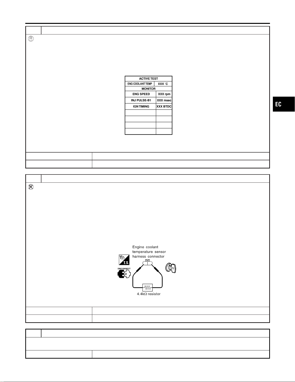
28 CHECK “CO” %
With CONSULT-II
1. Start engine and warm it up until engine coolant temperature indicator points to the middle of gauge.
2. Turn ignition switch “OFF”, wait at least 10 seconds and then turn “ON”.
3. Select “ENG COOLANT TEMP” in “ACTIVE TEST” mode.
4. Set “ENG COOLANT TEMP” to 5°C (41°F) by touching “DWN” and “Qd”.
5. Start engine and rev it (2,000 to 3,000 rpm) two or three times under no-load, then run engine at idle speed.
6. Check “CO” %.
SEF172Y
Idle CO: 0.7 - 9.9 % and engine runs smoothly.
OK or NG
OK © GO TO 31.
NG © GO TO 30.
29 CHECK “CO” %
Without CONSULT-II
1. Start engine and warm it up until engine coolant temperature indicator points to the middle of gauge.
2. Turn ignition switch “OFF”.
3. Disconnect engine coolant temperature sensor harness connector.
4. Connect a resistor (4.4 kΩ) between terminals of engine coolant temperature sensor harness connector.
5. Start engine and rev it (2,000 to 3,000 rpm) two or three times under no-load, then run engine at idle speed.
6. Check “CO” %.
Idle CO: 0.7 - 9.9 % and engine runs smoothly.
7. After checking “CO” %, turn ignition switch “OFF”, disconnect the resistor from the terminals of engine coolant tempera-
ture sensor harness connector, and then connect engine coolant temperature sensor harness connector to engine cool-
ant temperature sensor.
SEF982UA
OK or NG
OK © GO TO 31.
NG © GO TO 30.
30 RECONNECT HEATED OXYGEN SENSOR 1 HARNESS CONNECTOR
1. Turn ignition switch “OFF”.
2. Reconnect heated oxygen sensor 1 harness connector.
© GO TO 34.
GI
MA
EM
LC
FE
CL
MT
AT
AX
SU
BR
ST
RS
BT
HA
SC
EL
IDX
BASIC SERVICE PROCEDURE
Idle Speed/Ignition Timing/Idle Mixture Ratio Adjustment (Cont’d)
EC-69
31 REPLACE HEATED OXYGEN SENSOR 1
1. Stop engine.
2. Replace heated oxygen sensor 1 on the malfunctioning bank.
With CONSULT-II © GO TO 32.
Without CONSULT-II © GO TO 33.
32 CHECK HEATED OXYGEN SENSOR 1 (BANK 1)/(BANK 2) SIGNAL
With CONSULT-II
1. Start engine and warm it up until engine coolant temperature indicator points to the middle of gauge.
2. See “HO2S1 MNTR (B1)/(B2)” in “DATA MONITOR” mode.
3. Running engine at 2,000 rpm under no-load (The engine is warmed up to normal operating temperature.), check that
the monitor fluctuates between LEAN and RICH more than 5 times during 10 seconds.
1 time: RICH → LEAN → RICH
2 times: RICH → LEAN → RICH → LEAN → RICH
OK or NG
OK © GO TO 4.
NG © GO TO 34.
33 CHECK HEATED OXYGEN SENSOR 1 (BANK 1)/(BANK 2) SIGNAL
Without CONSULT-II
1. Set ECM to Self-diagnostic mode II (Heated oxygen sensor 1 monitor). Refer to “How to Switch Diagnostic Test Mode”,
EC-94.
2. Switch the monitored sensor to the malfunctioning bank. Refer to “How to Switch Monitored Sensor from Bank 1 to
Bank 2 or Vice Versa”, EC-94.
3. Running engine at 2,000 rpm under no-load (The engine is warmed up to normal operating temperature.), check that
the MIL comes on more than 5 times during 10 seconds.
OK or NG
OK © GO TO 4.
NG © GO TO 34.
34 DETECT MALFUNCTIONING PART
Check the following.
I Check mass air flow sensor and its circuit, and repair or replace if necessary. Refer to EC-195.
I Check injector and its circuit, and repair or replace if necessary. Refer to EC-703.
I Check engine coolant temperature sensor and its circuit, and repair or replace if necessary. Refer to EC-207.
I Check fuel pressure and repair or replace if necessary. Refer to EC-56.
OK or NG
OK © GO TO 36.
NG © 1. Repair or replace.
2. GO TO 35.
35 ERASE UNNECESSARY DTC
After this inspection, unnecessary DTC might be displayed.
Erase the stored memory in ECM and TCM. Refer to “How to Erase Emission-related Diagnostic Information”, EC-76 and
AT-38.
© GO TO 4.
BASIC SERVICE PROCEDURE
Idle Speed/Ignition Timing/Idle Mixture Ratio Adjustment (Cont’d)
EC-70
36 CHECK ECM FUNCTION
1. Substitute another known-good ECM to check ECM function. (ECM may be the cause of a problem, but this is the
rarely the case.)
2. Perform initialization of NVIS (NATS) system and registration of NVIS (NATS) ignition key IDs. Refer to “NVIS (NISSAN
VEHICLE IMMOBILIZER SYSTEM — NATS”, EC-92.
© GO TO 4.
Accelerator Pedal Released Position Learning
NFEC1186
DESCRIPTION
NFEC1186S01
“Accelerator Pedal Released Position Learning” is an operation to learn the fully released position of the
accelerator pedal by monitoring the accelerator pedal position sensor output signal. It must be performed each
time harness connector of accelerator pedal position sensor or ECM is disconnected.
OPERATION PROCEDURE
NFEC1186S02
1. Make sure that accelerator pedal is fully released.
2. Turn ignition switch “ON” and wait at least 2 seconds.
3. Turn ignition switch “OFF” wait at least 10 seconds.
4. Turn ignition switch “ON” and wait at least 2 seconds.
5. Turn ignition switch “OFF” wait at least 10 seconds.
Throttle Valve Closed Position Learning
NFEC1187
DESCRIPTION
NFEC1187S01
“Throttle Valve Closed Position Learning” is an operation to learn the fully closed position of the throttle valve
by monitorizing the throttle position sensor output signal. It must be performed each time harness connector
of electric throttle control actuator or ECM is disconnected.
OPERATION PROCEDURE
NFEC1187S02
1. Turn ignition switch “ON”.
2. Turn ignition switch “OFF” wait at least 10 seconds.
Make sure that throttle valve moves during above 10 seconds by confirming the operating sound.
Idle Air Volume Learning
NFEC1188
DESCRIPTION
NFEC1188S01
“Idle Air Volume Learning” is an operation to learn the idle air vol-
ume that keeps each engine within the specific range. It must be
performed under any of the following conditions:
I Each time electric throttle control actuator or ECM is replaced.
I Idle speed or ignition timing is out of specification.
PREPARATION
NFEC1188S02
Before performing “Idle Air Volume Learning”, make sure that all of
the following conditions are satisfied.
Learning will be cancelled if any of the following conditions are
missed for even a moment.
I Battery voltage: More than 12.9V (At idle)
I Engine coolant temperature: 70 - 99°C (158 - 210°F)
I PNP switch: ON
I Electric load switch: OFF
(Air conditioner, headlamp, rear window defogger)
On vehicles equipped with daytime light systems, set
lighting switch to the 1st position to light only small
lamps.
I Steering wheel: Neutral (Straight-ahead position)
GI
MA
EM
LC
FE
CL
MT
AT
AX
SU
BR
ST
RS
BT
HA
SC
EL
IDX
BASIC SERVICE PROCEDURE
Idle Speed/Ignition Timing/Idle Mixture Ratio Adjustment (Cont’d)
EC-71
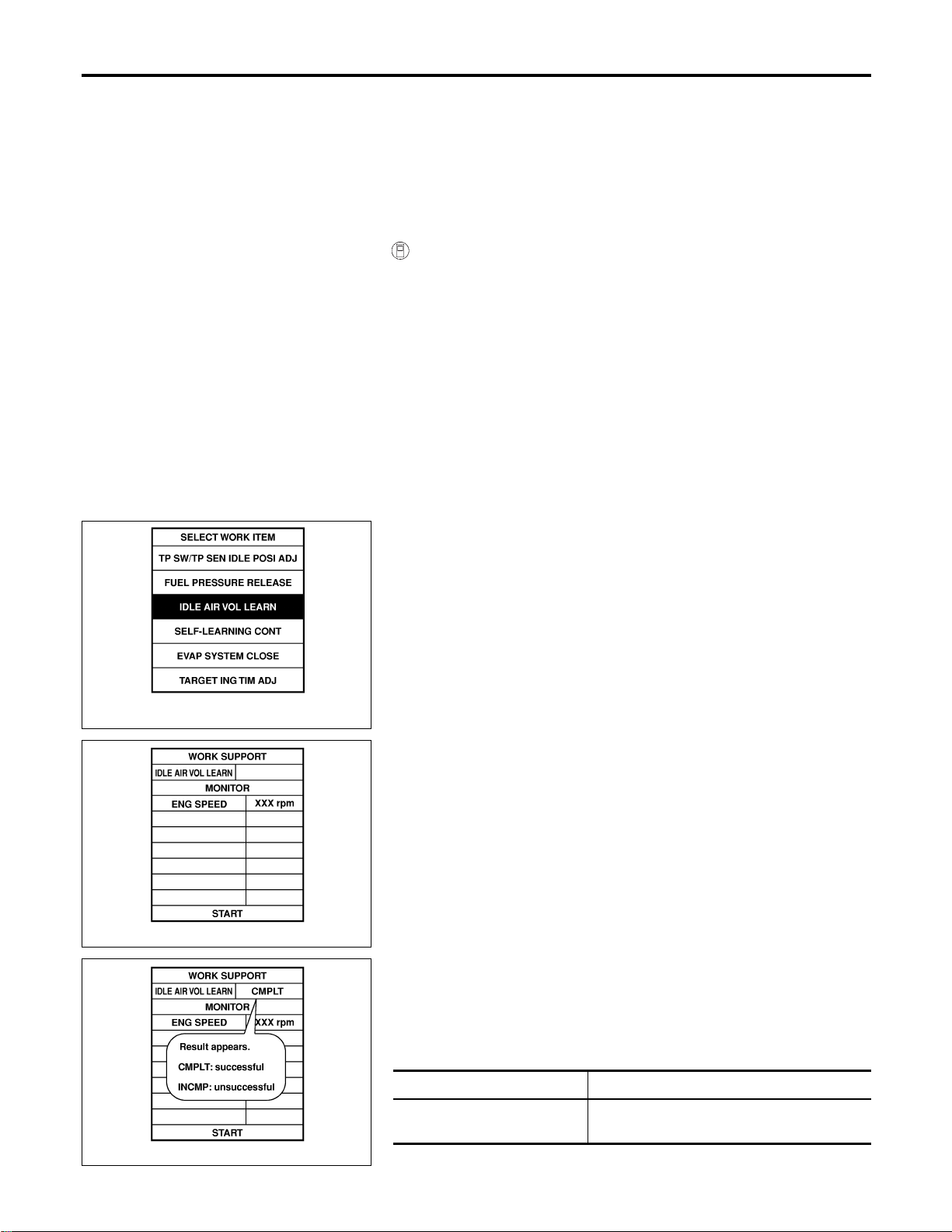
I Vehicle speed: Stopped
I Transmission: Warmed-up
For A/T models with CONSULT-II, drive vehicle until “FLUID
TEMP SE” in “DATA MONITOR” mode of “A/T” system indi-
cates less than 0.9V.
For A/T models without CONSULT-II and M/T models, drive
vehicle for 10 minutes.
OPERATION PROCEDURE
NFEC1188S03
With CONSULT-II
NFEC1188S0301
NOTE:
Before perform “Idle Air Volume Learning”, make sure that “Accel-
erator Pedal Released Position Learning” and “Throttle Valve
Closed Position Learning” are completed.
If not, perform “Accelerator Pedal Released Position Learning”,
EC-71 and “Throttle Valve Closed Position Learning”, EC-71.
1. Start engine and warm it up to normal operating temperature.
2. Check that all items listed under the topic “PRE-CONDITION-
ING” (previously mentioned) are in good order.
SEF452Y
3. Select “IDLE AIR VOL LEARN” in “WORK SUPPORT” mode.
SEF454Y
4. Touch “START” and wait 20 seconds.
SEF455Y
5. Make sure that “CMPLT” is displayed on CONSULT-II screen.
If “INCMP” is displayed, “Idle Air Volume Learning” will not be
carried out successfully. In this case, find the cause of the
problem by referring to the “Diagnostic Procedure” below.
6. Rev up the engine two or three times and make sure that idle
speed and ignition timing are within the specifications.
ITEM SPECIFICATION
Idle speed
MT: 625±50 rpm
AT: 675±50 rpm (in “P” or “N” position)
BASIC SERVICE PROCEDURE
Idle Air Volume Learning (Cont’d)
EC-72
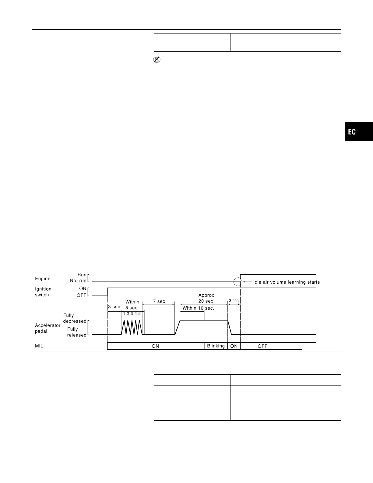
Ignition timing
MT: 15±5° BTDC
AT: 15±5° BTDC (in “P” or “N” position)
Without CONSULT-II
NFEC1188S0302
NOTE:
I It is better to count the time accurately with a clock.
I It is impossible to switch the diagnostic mode when an
accelerator pedal position sensor circuit has a malfunc-
tion.
NOTE:
Before perform “Idle Air Volume Learning”, make sure that “Accel-
erator Pedal Released Position Learning” and “Throttle Valve
Closed Position Learning” are completed.
If not, perform “Accelerator Pedal Released Position Learning”,
EC-71 and “Throttle Valve Closed Position Learning”, EC-71.
1. Start engine and warm it up to normal operating temperature.
2. Check that all items listed under the topic “PRE-CONDITION-
ING” (previously mentioned) are in good order.
3. Turn ignition switch “OFF” and wait at least 10 seconds.
4. Confirm that accelerator pedal is fully released, turn ignition
switch “ON” and wait 3 seconds.
5. Repeat the following procedure quickly five times within 5 sec-
onds.
1) Fully depress the accelerator pedal.
2) Fully release the accelerator pedal.
6. Wait 7 seconds, fully depress the accelerator pedal and keep
it for approx. 20 seconds until the MIL goes off.
7. Fully release the accelerator pedal within 3 seconds after the
MIL goes off.
8. Start engine and let it idle.
9. Wait 20 seconds.
SEC897C
10. Rev up the engine two or three times and make sure that idle
speed and ignition timing are within the specifications.
ITEM SPECIFICATION
Idle speed
MT: 625±50 rpm
AT: 675±50 rpm (in “P” or “N” position)
Ignition timing
MT: 15±5° BTDC
AT: 15±5° BTDC (in “P” or “N” position)
11. If idle speed and ignition timing are not within the specification,
the result will be incomplete. In this case, find the cause of the
problem by referring to the “Diagnostic Procedure” below.
GI
MA
EM
LC
FE
CL
MT
AT
AX
SU
BR
ST
RS
BT
HA
SC
EL
IDX
BASIC SERVICE PROCEDURE
Idle Air Volume Learning (Cont’d)
EC-73

DIAGNOSTIC PROCEDURE
NFEC1188S04
If idle air volume learning cannot be performed successfully,
proceed as follows:
1. Check that throttle valve is fully closed.
2. Check PCV valve operation.
3. Check that downstream of throttle valve is free from air
leakage.
4. When the above three items check out OK, engine com-
ponent parts and their installation condition are question-
able. Check and eliminate the cause of the problem.
It is useful to perform EC-152, “TROUBLE DIAGNOSIS -
SPECIFICATION VALUE”.
5. If any of the following conditions occur after the engine
has started, eliminate the cause of the problem and per-
form “Idle air volume learning” all over again:
− Engine stalls.
− Erroneous idle.
BASIC SERVICE PROCEDURE
Idle Air Volume Learning (Cont’d)
EC-74
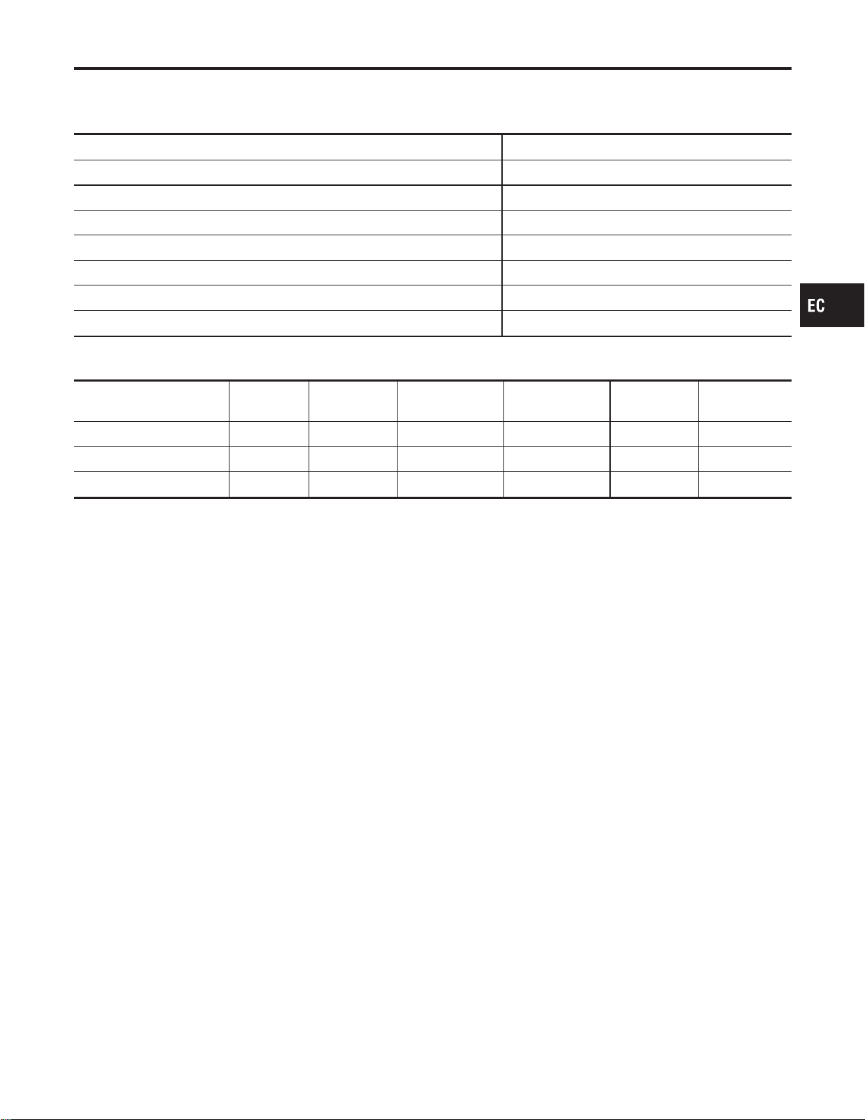
Introduction
NFEC1423
The ECM has an on board diagnostic system, which detects malfunctions related to engine sensors or actua-
tors. The ECM also records various emission-related diagnostic information including:
Emission-related diagnostic information SAE Mode
Diagnostic Trouble Code (DTC) Mode 3 of SAE J1979
Freeze Frame data Mode 2 of SAE J1979
System Readiness Test (SRT) code Mode 1 of SAE J1979
1st Trip Diagnostic Trouble Code (1st Trip DTC) Mode 7 of SAE J1979
1st Trip Freeze Frame data
Test values and Test limits Mode 6 of SAE J1979
Calibration ID Mode 9 of SAE J1979
The above information can be checked using procedures listed in the table below.
X: Applicable —: Not applicable
DTC 1st trip DTC
Freeze Frame
data
1st trip Freeze
Frame data
SRT code Test value
CONSULT-II X X X X X —
GST X X*1 X — X X
ECM X X*2 — — — —
*1: 1st trip DTCs for self-diagnoses concerning SRT items cannot be shown on the GST display.
*2: When DTC and 1st trip DTC simultaneously appear on the display, they cannot be clearly distinguished from each other.
The malfunction indicator lamp (MIL) on the instrument panel lights up when the same malfunction is detected
in two consecutive trips (Two trip detection logic), or when the ECM enters fail-safe mode. (Refer to EC-129.)
Two Trip Detection Logic
NFEC1424
When a malfunction is detected for the first time, 1st trip DTC and 1st trip Freeze Frame data are stored in
the ECM memory. The MIL will not light up at this stage. <1st trip>
If the same malfunction is detected again during the next drive, the DTC and Freeze Frame data are stored
in the ECM memory, and the MIL lights up. The MIL lights up at the same time when the DTC is stored. <2nd
trip> The “trip” in the “Two Trip Detection Logic” means a driving mode in which self-diagnosis is performed
during vehicle operation. Specific on board diagnostic items will cause the ECM to light up or blink the MIL,
and store DTC and Freeze Frame data, even in the 1st trip, as shown below.
GI
MA
EM
LC
FE
CL
MT
AT
AX
SU
BR
ST
RS
BT
HA
SC
EL
IDX
ON BOARD DIAGNOSTIC SYSTEM DESCRIPTION
Introduction
EC-75

X: Applicable —: Not Exit
Items
MIL DTC 1st trip DTC
1st trip 2nd trip
1st trip
displaying
2nd trip
displaying
1st trip
displaying
2nd trip
displaying
Blinking Lighting up Blinking
Lighting
up
Misfire (Possible three way catalyst
damage) — DTC: P0300 - P0306
is being detected
X — ————X—
Misfire (Possible three way catalyst
damage) — DTC: P0300 - P0306
is being detected
——X——X——
Throttle control motor — DTC:
P1128
—X——X———
Closed loop control
— DTC: P1148, P1168
—X——X———
Fail-safe items (Refer to EC-129.) — X — — X*1 — X*1 —
Except above — — — X — X X —
*1: Except “ECM”
Emission-related Diagnostic Information
NFEC0031
DTC AND 1ST TRIP DTC
NFEC0031S01
The 1st trip DTC (whose number is the same as the DTC number) is displayed for the latest self-diagnostic
result obtained. If the ECM memory was cleared previously, and the 1st trip DTC did not reoccur, the 1st trip
DTC will not be displayed.
If a malfunction is detected during the 1st trip, the 1st trip DTC is stored in the ECM memory. The MIL will not
light up (two trip detection logic). If the same malfunction is not detected in the 2nd trip (meeting the required
driving pattern), the 1st trip DTC is cleared from the ECM memory. If the same malfunction is detected in the
2nd trip, both the 1st trip DTC and DTC are stored in the ECM memory and the MIL lights up. In other words,
the DTC is stored in the ECM memory and the MIL lights up when the same malfunction occurs in two con-
secutive trips. If a 1st trip DTC is stored and a non-diagnostic operation is performed between the 1st and
2nd trips, only the 1st trip DTC will continue to be stored. For malfunctions that blink or light up the MIL dur-
ing the 1st trip, the DTC and 1st trip DTC are stored in the ECM memory.
Procedures for clearing the DTC and the 1st trip DTC from the ECM memory are described in “HOW TO
ERASE EMISSION-RELATED DIAGNOSTIC INFORMATION”, EC-91.
For malfunctions in which 1st trip DTCs are displayed, refer to EC-86. These items are required by legal
regulations to continuously monitor the system/component. In addition, the items monitored non-continuously
are also displayed on CONSULT-II.
1st trip DTC is specified in Mode 7 of SAE J1979. 1st trip DTC detection occurs without lighting up the MIL
and therefore does not warn the driver of a problem. However, 1st trip DTC detection will not prevent the
vehicle from being tested, for example during Inspection/Maintenance (I/M) tests.
When a 1st trip DTC is detected, check, print out or write down and erase (1st trip) DTC and Freeze Frame
data as specified in “Work Flow” procedure Step II, refer to EC-121. Then perform “DTC Confirmation Proce-
dure” or “Overall Function Check” to try to duplicate the problem. If the malfunction is duplicated, the item
requires repair.
How to Read DTC and 1st Trip DTC
NFEC0031S0101
DTC and 1st trip DTC can be read by the following methods.
With CONSULT-II
With GST
CONSULT-II or GST (Generic Scan Tool) Examples: P0117, P0340, P1065, etc.
These DTCs are prescribed by SAE J2012.
(CONSULT-II also displays the malfunctioning component or system.)
NO TOOLS
The number of blinks of the MIL in the Diagnostic Test Mode II (Self-Diagnostic Results) indicates the DTC.
Example: 0117, 0340, 1065, etc.
I 1st trip DTC No. is the same as DTC No.
ON BOARD DIAGNOSTIC SYSTEM DESCRIPTION
Two Trip Detection Logic (Cont’d)
EC-76
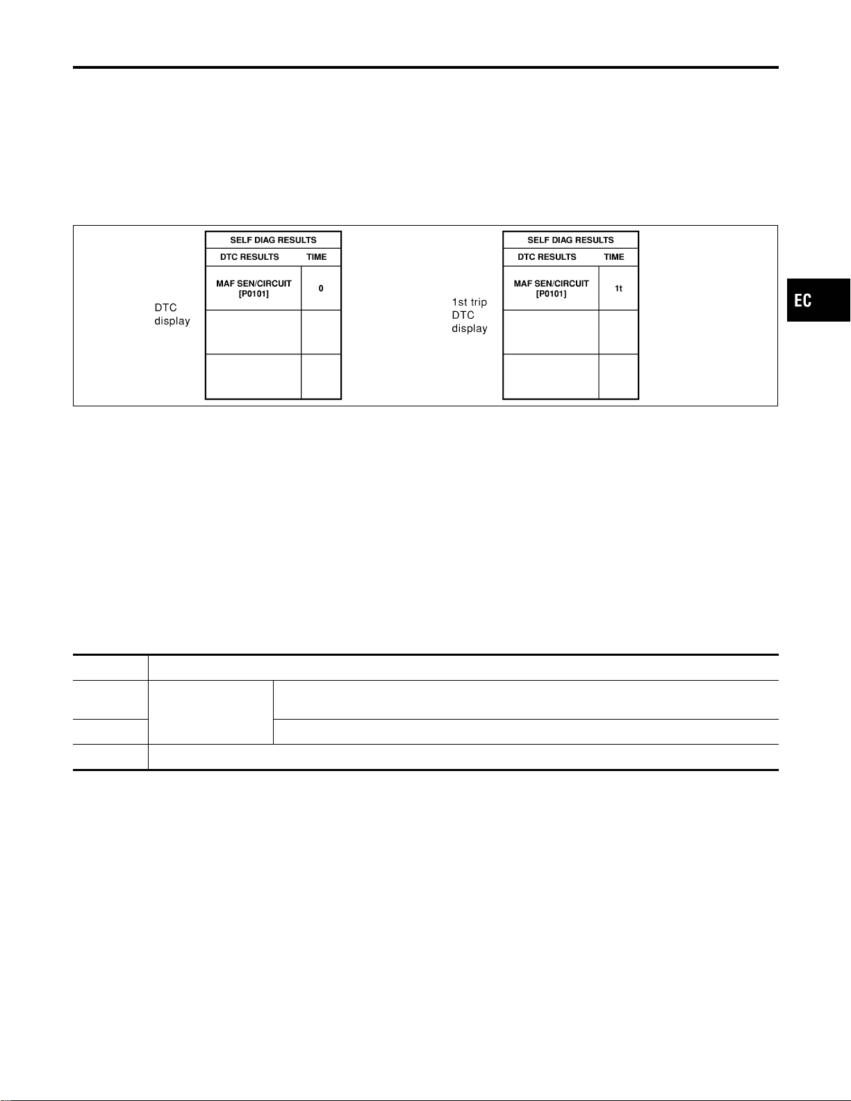
I Output of a DTC indicates a malfunction. However, GST or the Diagnostic Test Mode II does not
indicate whether the malfunction is still occurring or has occurred in the past and has returned to
normal. CONSULT-II can identify malfunction status as shown below. Therefore, using CONSULT-II
(if available) is recommended.
A sample of CONSULT-II display for DTC and 1st trip DTC is shown below. DTC or 1st trip DTC of a malfunc-
tion is displayed in SELF-DIAGNOSTIC RESULTS mode of CONSULT-II. Time data indicates how many times
the vehicle was driven after the last detection of a DTC.
If the DTC is being detected currently, the time data will be “0”.
If a 1st trip DTC is stored in the ECM, the time data will be “[1t]”.
SEC745C
FREEZE FRAME DATA AND 1ST TRIP FREEZE FRAME DATA
NFEC0031S02
The ECM records the driving conditions such as fuel system status, calculated load value, engine coolant
temperature, short term fuel trim, long term fuel trim, engine speed, vehicle speed and absolute pressure at
the moment a malfunction is detected.
Data which are stored in the ECM memory, along with the 1st trip DTC, are called 1st trip freeze frame data.
The data, stored together with the DTC data, are called freeze frame data and displayed on CONSULT-II or
GST. The 1st trip freeze frame data can only be displayed on the CONSULT-II screen, not on the GST. For
details, see EC-105.
Only one set of freeze frame data (either 1st trip freeze frame data or freeze frame data) can be stored in the
ECM. 1st trip freeze frame data is stored in the ECM memory along with the 1st trip DTC. There is no prior-
ity for 1st trip freeze frame data and it is updated each time a different 1st trip DTC is detected. However, once
freeze frame data (2nd trip detection/MIL on) is stored in the ECM memory, 1st trip freeze frame data is no
longer stored. Remember, only one set of freeze frame data can be stored in the ECM. The ECM has the fol-
lowing priorities to update the data.
Priority Items
1
Freeze frame data Misfire — DTC: P0300 - P0306
Fuel Injection System Function — DTC: P0171, P0172, P0174, P0175
2 Except the above items (Includes A/T related items)
3 1st trip freeze frame data
For example, the EGR malfunction (Priority: 2) was detected and the freeze frame data was stored in the 2nd
trip. After that when the misfire (Priority: 1) is detected in another trip, the freeze frame data will be updated
from the EGR malfunction to the misfire. The 1st trip freeze frame data is updated each time a different mal-
function is detected. There is no priority for 1st trip freeze frame data. However, once freeze frame data is
stored in the ECM memory, 1st trip freeze data is no longer stored (because only one freeze frame data or
1st trip freeze frame data can be stored in the ECM). If freeze frame data is stored in the ECM memory and
freeze frame data with the same priority occurs later, the first (original) freeze frame data remains unchanged
in the ECM memory.
Both 1st trip freeze frame data and freeze frame data (along with the DTCs) are cleared when the ECM
memory is erased. Procedures for clearing the ECM memory are described in “HOW TO ERASE EMISSION-
RELATED DIAGNOSTIC INFORMATION”, EC-91.
SYSTEM READINESS TEST (SRT) CODE
NFEC0031S03
System Readiness Test (SRT) code is specified in Mode 1 of SAE J1979.
As part of an enhanced emissions test for Inspection & Maintenance (I/M), certain states require the status of
SRT be used to indicate whether the ECM has completed self-diagnosis of major emission systems and com-
ponents. Completion must be verified in order for the emissions inspection to proceed.
GI
MA
EM
LC
FE
CL
MT
AT
AX
SU
BR
ST
RS
BT
HA
SC
EL
IDX
ON BOARD DIAGNOSTIC SYSTEM DESCRIPTION
Emission-related Diagnostic Information (Cont’d)
EC-77

If a vehicle is rejected for a State emissions inspection due to one or more SRT items indicating “INCMP”,
use the information in this Service Manual to set the SRT to “CMPLT”.
In most cases the ECM will automatically complete its self-diagnosis cycle during normal usage, and the SRT
status will indicate “CMPLT” for each application system. Once set as “CMPLT”, the SRT status remains
“CMPLT” until the self-diagnosis memory is erased.
Occasionally, certain portions of the self-diagnostic test may not be completed as a result of the customer’s
normal driving pattern; the SRT will indicate “INCMP” for these items.
NOTE:
The SRT will also indicate “INCMP” if the self-diagnosis memory is erased for any reason or if the ECM
memory power supply is interrupted for several hours.
If, during the state emissions inspection, the SRT indicates “CMPLT” for all test items, the inspector will con-
tinue with the emissions test. However, if the SRT indicates “INCMP” for one or more of the SRT items the
vehicle is returned to the customer untested.
NOTE:
If MILis “ON” during the state emissions inspection, the vehicle is also returned to the customer untested even
though the SRT indicates “CMPLT” for all test items. Therefore, it is important to check SRT (“CMPLT”) and
DTC (No DTCs) before the inspection.
ON BOARD DIAGNOSTIC SYSTEM DESCRIPTION
Emission-related Diagnostic Information (Cont’d)
EC-78

SRT Item
=NFEC0031S0310
The table below shows required self-diagnostic items to set the SRT to “CMPLT”.
SRT item
(CONSULT-II indica-
tion)
Perfor-
mance Pri-
ority*
Required self-diagnostic items to set the SRT to “CMPLT”
Corresponding
DTC No.
CATALYST 2 Three way catalyst function P0420, P0430
EVAP SYSTEM 1 EVAP control system P0442
2 EVAP control system P0456, P1456
2 EVAP control system purge flow monitoring P0441
HO2S 2 Heated oxygen sensor 1 P0132, P0152
Heated oxygen sensor 1 P0133, P0153
Heated oxygen sensor 1 P0134, P0154
Heated oxygen sensor 1 P1143, P1163
Heated oxygen sensor 1 P1144, P1164
Heated oxygen sensor 2 P0138, P0158
Heated oxygen sensor 2 P0139, P0159
Heated oxygen sensor 2 P1146, P1166
Heated oxygen sensor 2 P1147, P1167
HO2S HTR 2 Heated oxygen sensor 1 heater P0031, P0032, P0051,
P0052
Heated oxygen sensor 2 heater P0037, P0038, P0057,
P0058
*: If completion of several SRTs is required, perform driving patterns (DTC confirmation procedure), one by one based on the priority
for models with CONSULT-II.
GI
MA
EM
LC
FE
CL
MT
AT
AX
SU
BR
ST
RS
BT
HA
SC
EL
IDX
ON BOARD DIAGNOSTIC SYSTEM DESCRIPTION
Emission-related Diagnostic Information (Cont’d)
EC-79

SRT Set Timing
=NFEC0031S0311
SRT is set as “CMPLT” after self-diagnosis has been performed one or more times. Completion of SRT is done
regardless of whether the result is OK or NG. The set timing is different between OK and NG results and is
shown in the table below.
Self-diagnosis result
Example
Diagnosis
Ignition cycle
+ ON , OFF + ON , OFF + ON , OFF + ON ,
All OK Case 1 P0400 OK (1) — (1) OK (2) — (2)
P0402 OK (1) — (1) — (1) OK (2)
P1402 OK (1) OK (2) — (2) — (2)
SRT of EGR “CMPLT” “CMPLT” “CMPLT” “CMPLT”
Case 2 P0400 OK (1) — (1) — (1) — (1)
P0402 — (0) — (0) OK (1) — (1)
P1402 OK (1) OK (2) — (2) — (2)
SRT of EGR “INCMP” “INCMP” “CMPLT” “CMPLT”
NG exists Case 3 P0400 OK OK — —
P0402 — — — —
P1402 NG — NG
NG
(Consecutive NG)
(1st trip)
DTC
1st trip DTC — 1st trip DTC
DTC
(= MIL “ON”)
SRT of EGR “INCMP” “INCMP” “INCMP” “CMPLT”
OK: Self-diagnosis is carried out and the result is OK.
NG: Self-diagnosis is carried out and the result is NG.
—: Self-diagnosis is not carried out.
When all SRT related self-diagnoses showed OK results in a single cycle (Ignition OFF-ON-OFF), the SRT
will indicate “CMPLT”. , Case 1 above
When all SRT related self-diagnoses showed OK results through several different cycles, the SRT will indi-
cate “CMPLT” at the time the respective self-diagnoses have at least one OK result. , Case 2 above
If one or more SRT related self-diagnoses showed NG results in 2 consecutive cycles, the SRT will also indi-
cate “CMPLT”. , Case 3 above
The table above shows that the minimum number of cycles for setting SRT as “INCMP” is one (1) for each
self-diagnosis (Case1&2)ortwo(2)foroneofself-diagnoses (Case 3). However, in preparation for the state
emissions inspection, it is unnecessary of each self-diagnosis to be executed twice (Case 3) for the following
reasons:
I The SRT will indicate “CMPLT” at the time the respective self-diagnoses have one (1) OK result.
I The emissions inspection requires “CMPLT” of the SRT only with OK self-diagnosis results.
I When, during SRT driving pattern, 1st trip DTC (NG) is detected prior to “CMPLT” of SRT, the self-diag-
nosis memory must be erased from ECM after repair.
I If the 1st trip DTC is erased, all the SRT will indicate “INCMP”.
NOTE:
SRT can be set as “CMPLT” together with the DTC(s). Therefore, DTC check must always be carried out prior
to the state emission inspection even though the SRT indicates “CMPLT”.
SRT Service Procedure
NFEC0031S0312
If a vehicle has failed the state emissions inspection due to one or more SRT items indicating “INCMP”, review
the flowchart diagnostic sequence on the next page.
ON BOARD DIAGNOSTIC SYSTEM DESCRIPTION
Emission-related Diagnostic Information (Cont’d)
EC-80
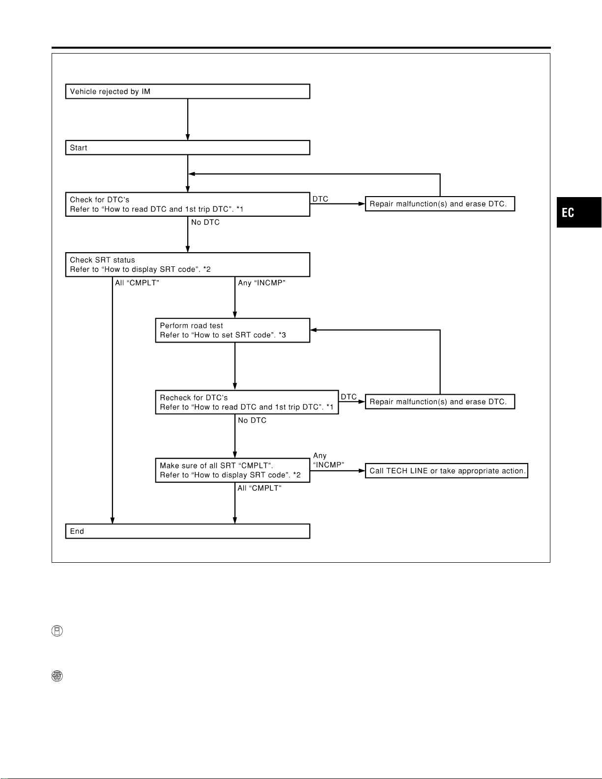
SEF170Z
*1 EC-76 *2 EC-81 *3 EC-82
How to Display SRT Code
NFEC0031S0301
With CONSULT-II
Selecting “SRT STATUS” in “DTC CONFIRMATION” mode with CONSULT-II.
For items whose SRT codes are set, a “CMPLT” is displayed on the CONSULT-II screen; for items whose SRT
codes are not set, “INCMP” is displayed.
With GST
Selecting Mode 1 with GST (Generic Scan Tool)
A sample of CONSULT-II display for SRT code is shown below.
“INCMP” means the self-diagnosis is incomplete and SRT is not set. “CMPLT” means the self-diagnosis is
complete and SRT is set.
GI
MA
EM
LC
FE
CL
MT
AT
AX
SU
BR
ST
RS
BT
HA
SC
EL
IDX
ON BOARD DIAGNOSTIC SYSTEM DESCRIPTION
Emission-related Diagnostic Information (Cont’d)
EC-81
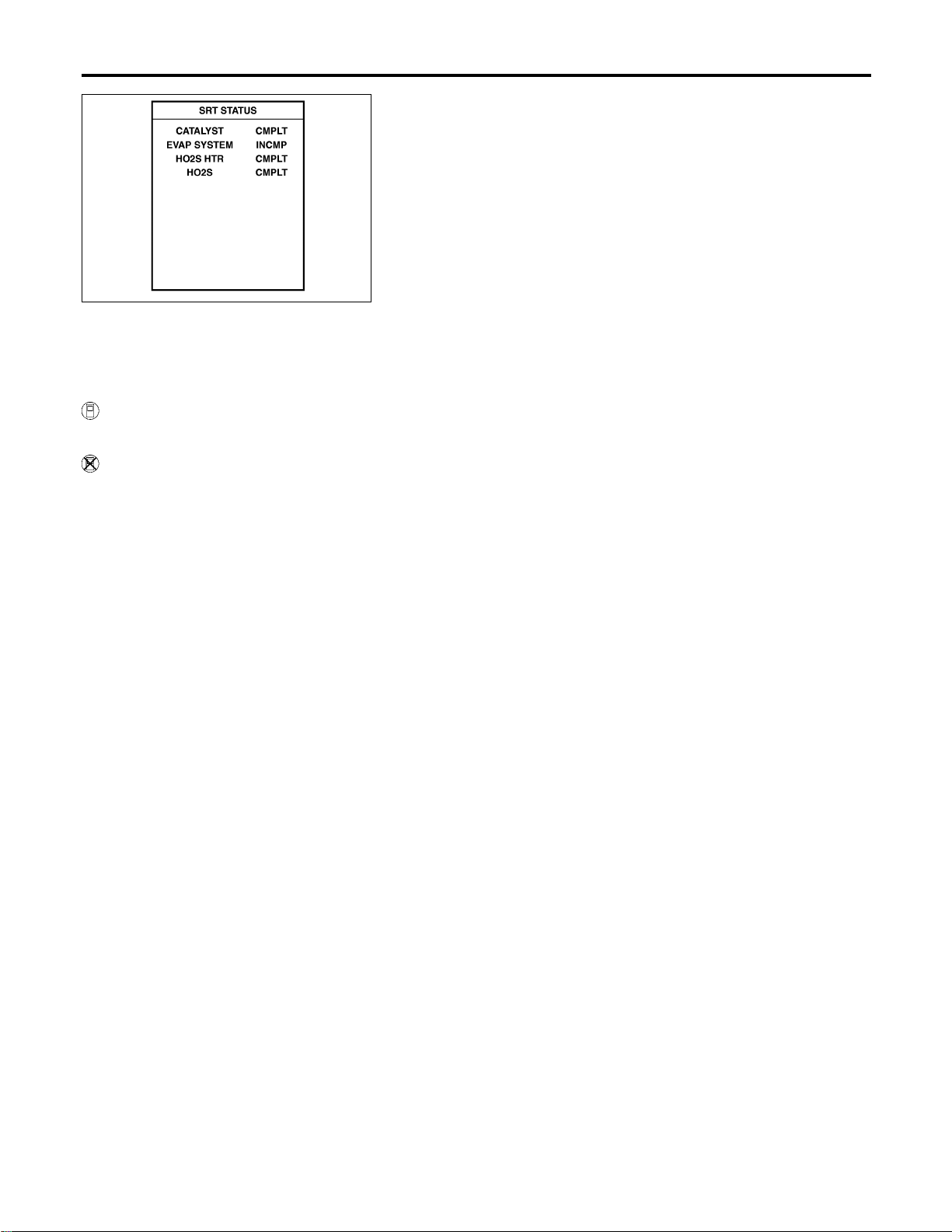
SEF949Z
How to Set SRT Code
NFEC0031S0302
To set all SRT codes, self-diagnosis for the items indicated above must be performed one or more times. Each
diagnosis may require a long period of actual driving under various conditions.
With CONSULT-II
Perform corresponding DTC Confirmation Procedure one by one based on “Performance Priority” in the table
on EC-79.
Without CONSULT-II
The most efficient driving pattern in which SRT codes can be properly set is explained on the next page. The
driving pattern should be performed one or more times to set all SRT codes.
ON BOARD DIAGNOSTIC SYSTEM DESCRIPTION
Emission-related Diagnostic Information (Cont’d)
EC-82
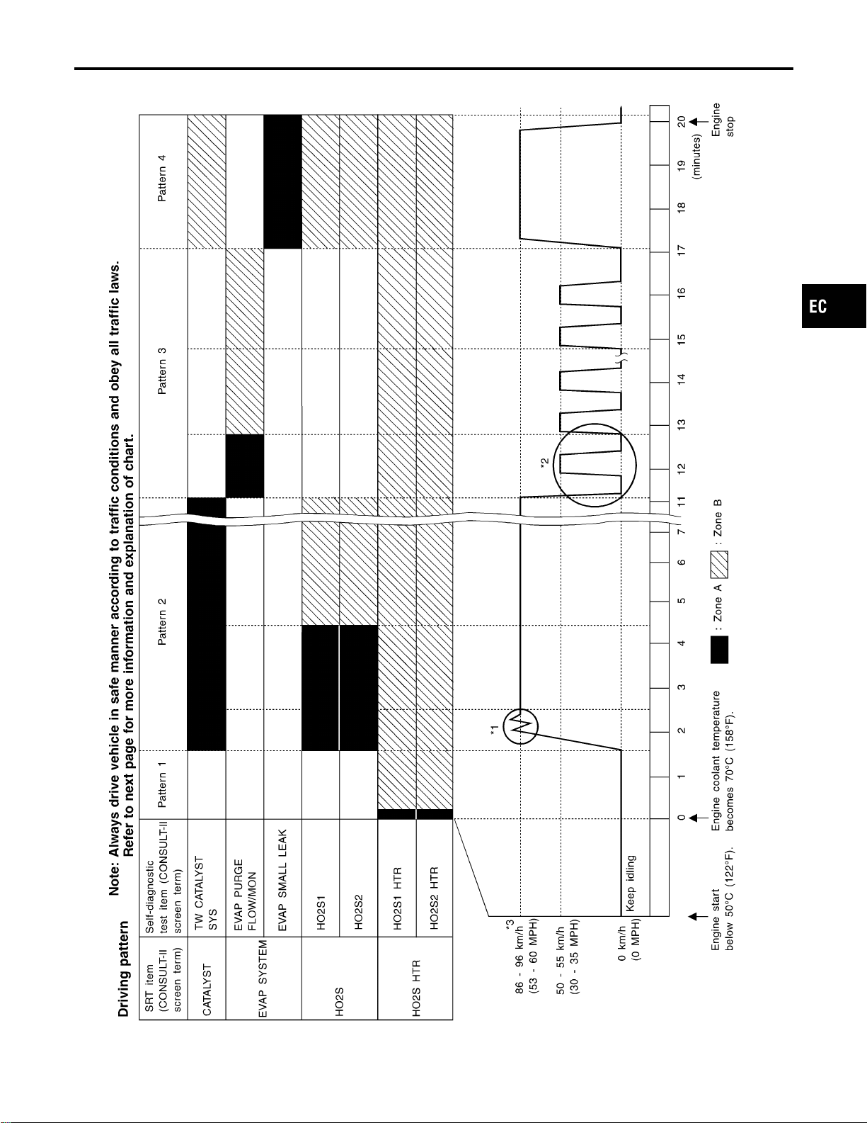
Driving Pattern
NFEC0031S0303
SEF947YC
GI
MA
EM
LC
FE
CL
MT
AT
AX
SU
BR
ST
RS
BT
HA
SC
EL
IDX
ON BOARD DIAGNOSTIC SYSTEM DESCRIPTION
Emission-related Diagnostic Information (Cont’d)
EC-83
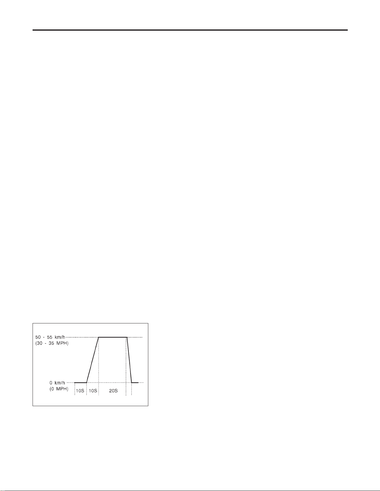
I The time required for each diagnosis varies with road surface conditions, weather, altitude, individual driv-
ing habits, etc.
Zone A refers to the range where the time required, for the diagnosis under normal conditions*, is the
shortest.
Zone B refers to the range where the diagnosis can still be performed if the diagnosis is not completed
within zone A.
*: Normal conditions refer to the following:
− Sea level
− Flat road
− Ambient air temperature: 20 - 30°C (68 - 86°F)
− Diagnosis is performed as quickly as possible under normal conditions.
Under different conditions [For example: ambient air temperature other than 20 - 30°C (68 - 86°F)], diag-
nosis may also be performed.
Pattern 1:
I The engine is started at the engine coolant temperature of −10 to 35°C (14 to 95°F)
(where the voltage between the ECM terminal 93 and ground is 3.0 - 4.3V).
I The engine must be operated at idle speed until the engine coolant temperature is greater than 70°C
(158°F) (where the voltage between the ECM terminal 93 and ground is lower than 1.4V).
I The engine is started at the fuel tank temperature of warmer than 0°C (32°F) (where the voltage
between the ECM terminal 75 and ground is less than 4.1V).
Pattern 2:
I When steady-state driving is performed again even after it is interrupted, each diagnosis can be conducted.
In this case, the time required for diagnosis may be extended.
Pattern 3:
I The driving pattern outlined in *2 must be repeated at least 3 times.
Pattern 4:
I Tests are performed after the engine has been operated for at least 17 minutes.
I The accelerator pedal must be held very steady during steady-state driving.
I If the accelerator pedal is moved, the test must be conducted all over again.
*1: Depress the accelerator pedal until vehicle speed is 90 km/h (56 MPH), then release the accelerator pedal
and keep it released for more than 10 seconds. Depress the accelerator pedal until vehicle speed is 90 km/h
(56 MPH) again.
*2: Operate the vehicle in the following driving pattern.
1) Decelerate vehicle to 0 km/h (0 MPH) and let engine idle.
2) Repeat driving pattern shown below at least 10 times.
I During acceleration, hold the accelerator pedal as steady as possible.
SEF414S
*3: Checking the vehicle speed with GST is advised.
Suggested Transmission Gear Position for A/T Models
Set the selector lever in the “D” position with the overdrive switch turned ON.
Suggested upshift speeds for M/T models
Shown below are suggested vehicle speeds for shifting into a higher gear. These suggestions relate to fuel
economy and vehicle performance. Actual upshift speeds will vary according to road conditions, the weather
and individual driving habits.
ON BOARD DIAGNOSTIC SYSTEM DESCRIPTION
Emission-related Diagnostic Information (Cont’d)
EC-84
For normal acceleration in low altitude areas
[less than 1,219 m (4,000 ft)]:
For quick acceleration in low altitude
areas and high altitude areas
[over 1,219 m (4,000 ft)]:
Gear change
ACCEL shift point
km/h (MPH)
CRUISE shift point
km/h (MPH)
km/h (MPH)
1st to 2nd 21 (13) 21 (13) 24 (15)
2nd to 3rd 37 (23) 26 (16) 40 (25)
3rd to 4th 53 (33) 44 (27) 64 (40)
4th to 5th 63 (39) 58 (36) 72 (45)
6th 80 (50) 80 (50) 80 (50)
Suggested Maximum Speed in Each Gear
Downshift to a lower gear if the engine is not running smoothly, or if you need to accelerate.
Do not exceed the maximum suggested speed (shown below) in any gear. For level road driving, use the
highest gear suggested for that speed. Always observe posted speed limits and drive according to the road
conditions to ensure safe operation. Do not over-rev the engine when shifting to a lower gear as it may cause
engine damage or loss of vehicle control.
Gear km/h (MPH)
1st 65 (40)
2nd 105 (65)
3rd —
4th —
5th —
6th —
TEST VALUE AND TEST LIMIT (GST ONLY — NOT APPLICABLE TO CONSULT-II)
NFEC0031S04
The following is the information specified in Mode 6 of SAE J1979.
The test value is a parameter used to determine whether a system/circuit diagnostic test is “OK” or “NG” while
being monitored by the ECM during self-diagnosis. The test limit is a reference value which is specified as the
maximum or minimum value and is compared with the test value being monitored.
Items for which these data (test value and test limit) are displayed are the same as SRT code items (30 test
items).
These data (test value and test limit) are specified by Test ID (TID) and Component ID (CID) and can be dis-
played on the GST screen.
X: Applicable —: Not applicable
SRT item Self-diagnostic test item
Test value (GST display)
Test limit Application
TID CID
CATALYST
Three way catalyst function
(Bank 1)
01H 01H Max. X
Three way catalyst function
(Bank 2)
03H 02H Max. X
EVAP SYSTEM
EVAP control system
(Small leak)
05H 03H Max. X
EVAP control system purge flow
monitoring
06H 83H Min. X
GI
MA
EM
LC
FE
CL
MT
AT
AX
SU
BR
ST
RS
BT
HA
SC
EL
IDX
ON BOARD DIAGNOSTIC SYSTEM DESCRIPTION
Emission-related Diagnostic Information (Cont’d)
EC-85
SRT item Self-diagnostic test item
Test value (GST display)
Test limit Application
TID CID
HO2S
Heated oxygen sensor 1 (bank 1)
09H 04H Max. X
0AH 84H Min. X
0BH 04H Max. X
0CH 04H Max. X
0DH 04H Max. X
Heated oxygen sensor 1 (bank 2)
11H 05H Max. X
12H 85H Min. X
13H 05H Max. X
14H 05H Max. X
15H 05H Max. X
Heated oxygen sensor 2 (bank 1)
19H 86H Min. X
1AH 86H Min. X
1BH 06H Max. X
1CH 06H Max. X
Heated oxygen sensor 2 (bank 2)
21H 87H Min. X
22H 87H Min. X
23H 07H Max. X
24H 07H Max. X
HO2S HTR
Heated oxygen sensor 1 heater
(bank 1)
29H 08H Max. X
2AH 88H Min. X
Heated oxygen sensor 1 heater
(bank 2)
2BH 09H Max. X
2CH 89H Min. X
Heated oxygen sensor 2 heater
(bank 1)
2DH 0AH Max. X
2EH 8AH Min. X
Heated oxygen sensor 2 heater
(bank 2)
2FH 0BH Max. X
30H 8BH Min. X
EMISSION-RELATED DIAGNOSTIC INFORMATION ITEMS
NFEC0031S05
X: Applicable —: Not applicable
Items
(CONSULT-II screen terms)
DTC*1
SRT code
Test value/
Test limit
(GST only)
1st trip
DTC*1
Reference
page
CONSULT-II
GST*2
ECM*3
CAN COMM CIRCUIT U1000 1000*6 — — X EC-164
CAN COMM CIRCUIT U1001 1001*6 — — X EC-164
NO DTC IS DETECTED.
FURTHER TESTING
MAY BE REQUIRED.
P0000 0000 — — — —
INT/V TIM CONT-B1 P0011 0011 — — X EC-167
INT/V TIM CONT-B2 P0021 0021 — — X EC-167
ON BOARD DIAGNOSTIC SYSTEM DESCRIPTION
Emission-related Diagnostic Information (Cont’d)
EC-86
Items
(CONSULT-II screen terms)
DTC*1
SRT code
Test value/
Test limit
(GST only)
1st trip
DTC*1
Reference
page
CONSULT-II
GST*2
ECM*3
HO2S1 HTR (B1) P0031 0031 X X X*5 EC-175
HO2S1 HTR (B1) P0032 0032 X X X*5 EC-175
HO2S2 HTR (B1) P0037 0037 X X X*5 EC-181
HO2S2 HTR (B1) P0038 0038 X X X*5 EC-181
HO2S1 HTR (B2) P0051 0051 X X X*5 EC-175
HO2S1 HTR (B2) P0052 0052 X X X*5 EC-175
HO2S2 HTR (B2) P0057 0057 X X X*5 EC-181
HO2S2 HTR (B2) P0058 0058 X X X*5 EC-181
MAF SEN/CIRCUIT P0101 0101 — — X EC-188
MAF SEN/CIRCUIT*8 P0102 0102 — — — EC-195
MAF SEN/CIRCUIT*8 P0103 0103 — — — EC-195
ABSL PRES SEN/CIRC P0107 0107 — — X EC-201
ABSL PRES SEN/CIRC P0108 0108 — — X EC-201
IAT SEN/CIRCUIT P0112 0112 — — X EC-203
IAT SEN/CIRCUIT P0113 0113 — — X EC-203
ECT SEN/CIRC*8 P0117 0117 — — — EC-207
ECT SEN/CIRC*8 P0118 0118 — — — EC-207
APP SEN/CIRCUIT*8 P0121 0121 — — — EC-212
TP SEN/CIRCUIT*8 P0122 0122 — — — EC-212
TP SEN/CIRCUIT*8 P0123 0123 — — — EC-212
ECT SENSOR P0125 0125 — — X EC-213
IAT SENSOR P0127 0127 — — X EC-216
THERMSTAT FNCTN P0128 0128 — — X EC-218
HO2S1 (B1) P0132 0132 X X X*5 EC-220
HO2S1 (B1) P0133 0133 X X X*5 EC-228
HO2S1 (B1) P0134 0134 X X X*5 EC-240
HO2S2 (B1) P0138 0138 X X X*5 EC-249
HO2S2 (B1) P0139 0139 X X X*5 EC-257
HO2S1 (B2) P0152 0152 X X X*5 EC-220
HO2S1 (B2) P0153 0153 X X X*5 EC-228
HO2S1 (B2) P0154 0154 X X X*5 EC-240
HO2S2 (B2) P0158 0158 X X X*5 EC-249
HO2S2 (B2) P0159 0159 X X X*5 EC-257
FUEL SYS-LEAN-B1 P0171 0171 — — X EC-267
FUEL SYS-RICH-B1 P0172 0172 — — X EC-275
FUEL SYS-LEAN-B2 P0174 0174 — — X EC-267
GI
MA
EM
LC
FE
CL
MT
AT
AX
SU
BR
ST
RS
BT
HA
SC
EL
IDX
ON BOARD DIAGNOSTIC SYSTEM DESCRIPTION
Emission-related Diagnostic Information (Cont’d)
EC-87

Items
(CONSULT-II screen terms)
DTC*1
SRT code
Test value/
Test limit
(GST only)
1st trip
DTC*1
Reference
page
CONSULT-II
GST*2
ECM*3
FUEL SYS-RICH-B2 P0175 0175 — — X EC-275
FTT SENSOR P0181 0181 — — X EC-282
FTT SEN/CIRCUIT P0182 0182 — — X EC-285
FTT SEN/CIRCUIT P0183 0183 — — X EC-285
TP SENSOR*8 P0221 0221 — — — EC-290
TP SEN 1/CIRC*8 P0222 0222 — — — EC-297
TP SEN 1/CIRC*8 P0223 0223 — — — EC-297
APP SENSOR*8 P0226 0226 — — — EC-304
APP SEN 1/CIRC*8 P0227 0227 — — — EC-311
APP SEN 1/CIRC*8 P0228 0228 — — — EC-311
MULTI CYL MISFIRE P0300 0300 — — X EC-317
CYL 1 MISFIRE P0301 0301 — — X EC-317
CYL 2 MISFIRE P0302 0302 — — X EC-317
CYL 3 MISFIRE P0303 0303 — — X EC-317
CYL 4 MISFIRE P0304 0304 — — X EC-317
CYL 5 MISFIRE P0305 0305 — — X EC-317
CYL 6 MISFIRE P0306 0306 — — X EC-317
KNOCK SEN/CIRC-B1 P0327 0327 — — — EC-325
KNOCK SEN/CIRC-B1 P0328 0328 — — — EC-325
CKP SEN/CIRCUIT P0335 0335 — — X EC-330
CMP SEN/CIRCUIT P0340 0340 — — X EC-337
CMP SEN/CIRC-B2 P0345 0345 — — X EC-337
TW CATALYST SYS-B1 P0420 0420 X X X*5 EC-346
TW CATALYST SYS-B2 P0430 0430 X X X*5 EC-346
EVAP PURG FLOW/MON P0441 0441 X X X*5 EC-351
EVAP SMALL LEAK P0442 0442 X X X*5 EC-361
PURG VOLUME CONT/V P0444 0444 — — X EC-376
PURG VOLUME CONT/V P0445 0445 — — X EC-376
VENT CONTROL VALVE P0447 0447 — — X EC-383
EVAP SYS PRES SEN P0452 0452 — — X EC-390
EVAP SYS PRES SEN P0453 0453 — — X EC-396
EVAP GROSS LEAK P0455 0455 — X X*5 EC-405
EVAP VERY SML LEAK P0456 0456 X*4 X X*5 EC-417
FUEL LEV SEN SLOSH P0460 0460 — — X EC-432
FUEL LEVEL SENSOR P0461 0461 — — X EC-436
FUEL LEVL SEN/CIRC P0462 0462 — — X EC-438
ON BOARD DIAGNOSTIC SYSTEM DESCRIPTION
Emission-related Diagnostic Information (Cont’d)
EC-88
Items
(CONSULT-II screen terms)
DTC*1
SRT code
Test value/
Test limit
(GST only)
1st trip
DTC*1
Reference
page
CONSULT-II
GST*2
ECM*3
FUEL LEVL SEN/CIRC P0463 0463 — — X EC-438
VEH SPEED SEN/CIRC*7 P0500 0500 — — X EC-442
ISC SYSTEM P0506 0506 — — X EC-446
ISC SYSTEM P0507 0507 — — X EC-448
PW ST P SEN/CIRC P0550 0550 — — X EC-450
ECM P0605 0605 — — X EC-455
MIL/CIRC P0650 0650 — — X EC-457
PNP SW/CIRC P0705 0705 — — X AT-104
ATF TEMP SEN/CIRC P0710 0710 — — X AT-110
VEH SPD SEN/CIR AT*7 P0720 0720 — — X AT-116
ENGINE SPEED SIG P0725 0725 — — X AT-121
A/T 1ST GR FNCTN P0731 0731 — — X AT-126
A/T 2ND GR FNCTN P0732 0732 — — X AT-132
A/T 3RD GR FNCTN P0733 0733 — — X AT-138
A/T 4TH GR FNCTN P0734 0734 — — X AT-144
TCC SOLENOID/CIRC P0740 0740 — — X AT-153
A/T TCC S/V FNCTN P0744 0744 — — X AT-158
L/PRESS SOL/CIRC P0745 0745 — — X AT-168
SFT SOL A/CIRC*8 P0750 0750 — — — AT-174
SFT SOL B/CIRC*8 P0755 0755 — — — AT-179
ECM BACK UP/CIRCUIT P1065 1065 — — X EC-461
MAF SENSOR*8 P1102 1102 — — — EC-465
ETC ACTR*8 P1121 1121 — — — EC-471
ETC FUNCTION/CIRC*8 P1122 1122 — — — EC-473
ETC MOT PWR P1124 1124 — — X EC-481
ETC MOT PWR*8 P1126 1126 — — — EC-481
ETC MOT P1128 1128 — — — EC-487
HO2S1 (B1) P1143 1143 X X X*5 EC-492
HO2S1 (B1) P1144 1144 X X X*5 EC-499
HO2S2 (B1) P1146 1146 X X X*5 EC-506
HO2S2 (B1) P1147 1147 X X X*5 EC-516
CLOSED LOOP-B1 P1148 1148 — — — EC-526
HO2S1 (B2) P1163 1163 X X X*5 EC-492
HO2S1 (B2) P1164 1164 X X X*5 EC-499
HO2S2 (B2) P1166 1166 X X X*5 EC-506
HO2S2 (B2) P1167 1167 X X X*5 EC-516
GI
MA
EM
LC
FE
CL
MT
AT
AX
SU
BR
ST
RS
BT
HA
SC
EL
IDX
ON BOARD DIAGNOSTIC SYSTEM DESCRIPTION
Emission-related Diagnostic Information (Cont’d)
EC-89

Items
(CONSULT-II screen terms)
DTC*1
SRT code
Test value/
Test limit
(GST only)
1st trip
DTC*1
Reference
page
CONSULT-II
GST*2
ECM*3
CLOSED LOOP-B2 P1168 1168 — — — EC-526
TCS C/U FUNCTN P1211 1211 — — X EC-528
TCS/CIRC P1212 1212 — — X EC-530
ENG OVER TEMP P1217 1217 — — X EC-532
TP SEN 2/CIRC*8 P1223 1223 — — — EC-550
TP SEN 2/CIRC*8 P1224 1224 — — — EC-550
CTP LEARNING P1225 1225 — — X EC-557
CTP LEARNING P1226 1226 — — X EC-559
APP SEN 2/CIRC*8 P1227 1227 — — — EC-561
APP SEN 2/CIRC*8 P1228 1228 — — — EC-561
SENSOR POWER/CIRC*8 P1229 1229 — — — EC-567
PURG VOLUME CONT/V P1444 1444 — — X EC-573
VENT CONTROL VALVE P1446 1446 — — X EC-586
VENT CONTROL VALVE P1448 1448 — — X EC-594
EVAP VERY SML LEAK P1456 1456 X*4 X X*5 EC-603
FUEL LEVL SEN/CIRC P1464 1464 — — X EC-619
VC/V BYPASS/V P1490 1490 — — X EC-622
VC CUT/V BYPASS/V P1491 1491 — — X EC-628
ASCD SW P1564 1564 — — X EC-640
ASCD BRAKE SW P1572 1572 — — X EC-647
ASCD VHL SPD SEN P1574 1574 — — X EC-662
NATS MALFUNCTION
P1610-
P1615
1610-1615 — — X EL-356
TP SEN/CIRC A/T P1705 1705 — — X AT-184
P-N POS SW/CIRCUIT P1706 1706 — — X EC-667
O/R CLTCH SOL/CIRC P1760 1760 — — X AT-191
VIAS S/V CIRC P1800 1800 — — X EC-673
BRAKE SW/CIRCUIT P1805 1805 — — X EC-678
*1: 1st trip DTC No. is the same as DTC No.
*2: These numbers are prescribed by SAE J2012.
*3: In Diagnostic Test Mode II (Self-diagnostic results), these numbers are controlled by NISSAN.
*4: SRT code will not be set if the self-diagnostic result is NG.
*5: These are not displayed with GST.
*6: The troubleshooting for this DTC needs CONSULT-II.
*7: When the fail-safe operations for both self-diagnoses occur at the same time, the MIL illuminates.
*8: When the fail-safe operation occurs, the MIL illuminates.
NOTE:
Regarding A33 models, “-B1” indicates bank 1 and “-B2” indicates bank 2.
ON BOARD DIAGNOSTIC SYSTEM DESCRIPTION
Emission-related Diagnostic Information (Cont’d)
EC-90
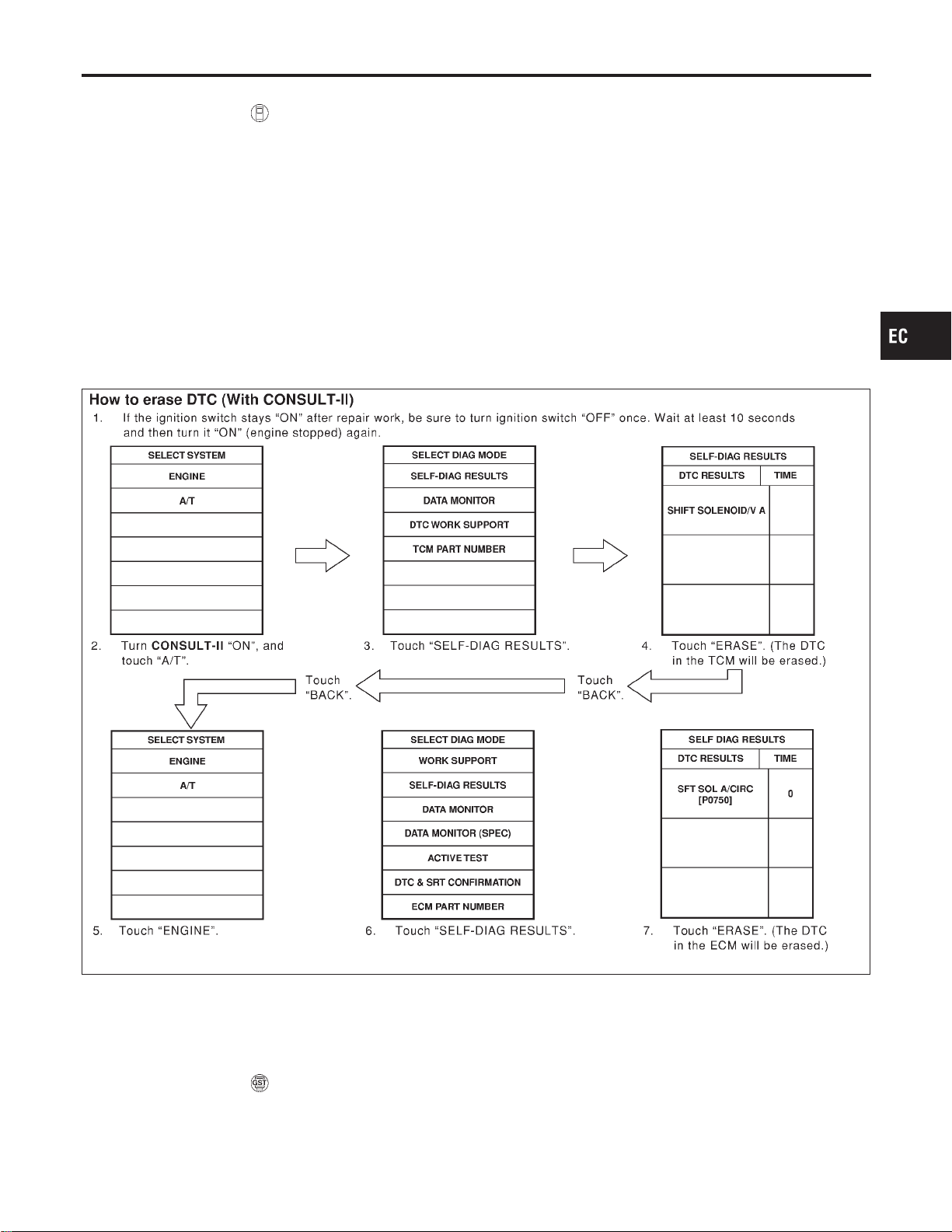
HOW TO ERASE EMISSION-RELATED DIAGNOSTIC INFORMATION
NFEC0031S06
How to Erase DTC ( With CONSULT-II)
NFEC0031S0601
NOTE:
If the DTC is not for A/T related items (see EC-9), skip steps 2 through 4.
1. If the ignition switch stays “ON” after repair work, be sure to turn ignition switch “OFF” once. Wait at least
10 seconds and then turn it “ON” (engine stopped) again.
2. Turn CONSULT-II “ON” and touch “A/T”.
3. Touch “SELF-DIAG RESULTS”.
4. Touch “ERASE”. [The DTC in the TCM (Transmission control module) will be erased.] Then touch “BACK”
twice.
5. Touch “ENGINE”.
6. Touch “SELF-DIAG RESULTS”.
7. Touch “ERASE”. (The DTC in the ECM will be erased.)
I If DTCs are displayed for both ECM and TCM (Transmission control module), they need to be erased
individually from the ECM and TCM (Transmission control module).
SEF823YA
The emission related diagnostic information in the ECM can be erased by selecting “ERASE” in the “SELF-
DIAG RESULTS” mode with CONSULT-II.
If DTCs are displayed for both ECM and TCM (Transmission control module), they need to be erased indi-
vidually from the ECM and TCM (Transmission control module).
How to Erase DTC ( With GST)
NFEC0031S0602
NOTE:
If the DTC is not for A/T related items (see EC-9), skip step 2.
1. If the ignition switch stays “ON” after repair work, be sure to turn ignition switch “OFF” once. Wait at least
10 seconds and then turn it “ON” (engine stopped) again.
GI
MA
EM
LC
FE
CL
MT
AT
AX
SU
BR
ST
RS
BT
HA
SC
EL
IDX
ON BOARD DIAGNOSTIC SYSTEM DESCRIPTION
Emission-related Diagnostic Information (Cont’d)
EC-91
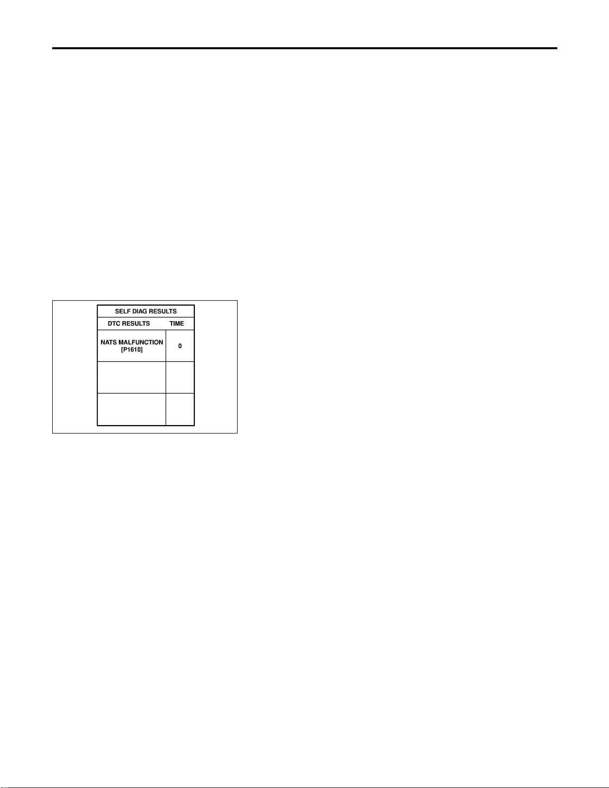
2. Perform “SELF-DIAGNOSTIC PROCEDURE (Without CONSULT-II)” in AT section titled “TROUBLE
DIAGNOSIS”, “Self-diagnosis”. (The engine warm-up step can be skipped when performing the diagnosis
only to erase the DTC.)
3. Select Mode 4 with GST (Generic Scan Tool).
The emission related diagnostic information in the ECM can be erased by selecting Mode 4 with GST.
I If the battery is disconnected, the emission-related diagnostic information will be lost after approx.
24 hours.
I The following data are cleared when the ECM memory is erased.
1) Diagnostic trouble codes
2) 1st trip diagnostic trouble codes
3) Freeze frame data
4) 1st trip freeze frame data
5) System readiness test (SRT) codes
6) Test values
7) Others
Actual work procedures are explained using a DTC as an example. Be careful so that not only the DTC, but
all of the data listed above, are cleared from the ECM memory during work procedures.
NVIS (NISSAN VEHICLE IMMOBILIZER SYSTEM — NATS)
NFEC0031S08
SEF515Y
I If the security indicator lights up with the ignition switch in the “ON” position or “NATS MALFUNC-
TION” is displayed on “SELF-DIAG RESULTS” screen, perform self-diagnostic results mode with
CONSULT-II using NATS program card. Refer to “NVIS (Nissan Vehicle Immobilizer System —
NATS)” EL-356.
I Confirm no self-diagnostic results of NVIS (NATS) is displayed before touching “ERASE” in “SELF-
DIAG RESULTS” mode with CONSULT-II.
I When replacing ECM, initialization of NVIS (NATS) system and registration of all NVIS (NATS) igni-
tion key IDs must be carried out with CONSULT-II using NATS program card.
Therefore, be sure to receive all keys from vehicle owner. Regarding the procedures of NVIS (NATS)
initialization and NVIS (NATS) ignition key ID registration, refer to CONSULT-II operation manual,
IVIS/NVIS.
Malfunction Indicator Lamp (MIL)
NFEC1189
DESCRIPTION
NFEC1189S01
The MIL is located on the instrument panel.
1. The MILwill light up when the ignition switch is turned ON without the engine running. This is a bulb check.
I IftheMILdoesnotlightup,referto“WARNING LAMPS”,EL-136orseeDTCP0650MIL(CIRCUIT),EC-457.
2. When the engine is started, the MIL should go off. If the MIL remains on, the on board diagnostic system
has detected an engine system malfunction.
ON BOARD DIAGNOSTIC SYSTEM DESCRIPTION
Emission-related Diagnostic Information (Cont’d)
EC-92
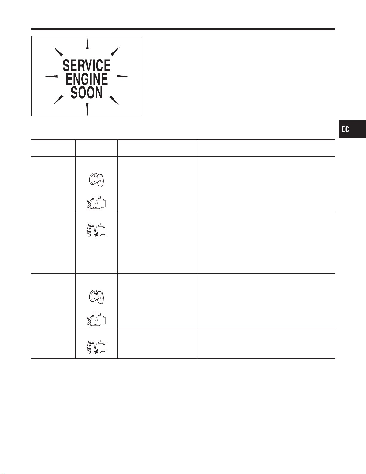
SEF217U
ON BOARD DIAGNOSTIC SYSTEM FUNCTION
NFEC1189S02
The on board diagnostic system has the following four functions.
Diagnostic Test
Mode
KEY and ENG.
Status
Function Explanation of Function
Mode I Ignition switch in
“ON” position
Engine stopped
BULB CHECK This function checks the MIL bulb for damage (blown,
open circuit, etc.).
If the MIL does not come on, check MIL circuit.
Engine running
MALFUNCTION WARNING This is a usual driving condition. When a malfunction is
detected twice in two consecutive driving cycles (two trip
detection logic), the MIL will light up to inform the driver
that a malfunction has been detected. The following mal-
functions will light up or blink the MIL in the 1st trip.
I “Misfire (Possible three way catalyst damage)”
I “Throttle control motor”
I “Closed loop control”
I Fail-safe mode
Mode II Ignition switch in
“ON” position
Engine stopped
SELF-DIAGNOSTIC RESULTS This function allows DTCs and 1st trip DTCs to be read.
Engine running
HEATED OXYGEN SENSOR 1
MONITOR
This function allows the fuel mixture condition (lean or
rich), monitored by heated oxygen sensor 1, to be read.
MIL Flashing without DTC
NFEC1189S0201
If the ECM is in Diagnostic Test Mode II, MIL may flash when engine is running. In this case, check ECM
diagnostic test mode. How to Switch Diagnostic Test Mode.
How to switch the diagnostic test (function) modes, and details of the above functions are described later.How
to Switch Diagnostic Test Mode.
The following emission-related diagnostic information is cleared when the ECM memory is erased.
1. Diagnostic trouble codes
2. 1st trip diagnostic trouble codes
3. Freeze frame data
4. 1st trip freeze frame data
5. System readiness test (SRT) codes
GI
MA
EM
LC
FE
CL
MT
AT
AX
SU
BR
ST
RS
BT
HA
SC
EL
IDX
ON BOARD DIAGNOSTIC SYSTEM DESCRIPTION
Malfunction Indicator Lamp (MIL) (Cont’d)
EC-93
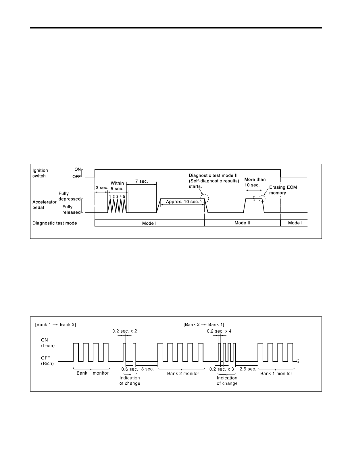
6. Test values
7. Others
HOW TO SWITCH DIAGNOSTIC TEST MODE
NFEC1189S03
NOTE:
I It is better to count the time accurately with a clock.
I It is impossible to switch the diagnostic mode when an accelerator pedal position sensor circuit
has a malfunction.
I Always ECM returns to Diagnostic Test Mode I after ignition switch is turned “OFF”.
How to Set Diagnostic Test Mode II (Self-diagnostic Results)
NFEC1189S0301
1. Confirm that accelerator pedal is fully released, turn ignition switch “ON” and wait 3 seconds.
2. Repeat the following procedure quickly five times within 5 seconds.
1) Fully depress the accelerator pedal.
2) Fully release the accelerator pedal.
3. Wait 7 seconds, fully depress the accelerator pedal and keep it for approx. 10 seconds until the MIL starts
blinking.
4. Fully release the accelerator pedal.
ECM has entered to Diagnostic Test Mode II (Self-diagnostic results).
PBIB0092E
How to Set Diagnostic Test Mode II (Heated Oxygen Sensor 1 Monitor)
NFEC1189S0302
1. Set the ECM in Diagnostic Test Mode II (Self-diagnostic results). Refer to How to Set Diagnostic Test Mode
II (Self-diagnostic Results).
2. Start Engine.
ECM has entered to Diagnostic Test Mode II (Heated oxygen sensor 1 monitor).
ECM will start heated oxygen sensor 1 monitoring from the bank 1 sensor.
How to Set Diagnostic Switch Monitored Sensor from Bank 1 to Bank 2 or Vice versa
NFEC1189S0303
1. Fully depress the accelerator pedal quickly and then release it immediately.
2. Make sure that monitoring sensor has changed by MIL blinking as follows.
PBIB0093E
How to Erase Diagnostic Test Mode II (Self-diagnostic Results)
NFEC1189S0304
1. Set ECM in Diagnostic Test Mode II (Self-diagnostic results). Refer to How to Set Diagnostic Test Mode
II (Self-diagnostic Results).
2. Fully depress the accelerator pedal and keep it for more than 10 seconds. The emission-related diagnos-
tic information has been erased from the backup memory in the ECM.
ON BOARD DIAGNOSTIC SYSTEM DESCRIPTION
Malfunction Indicator Lamp (MIL) (Cont’d)
EC-94
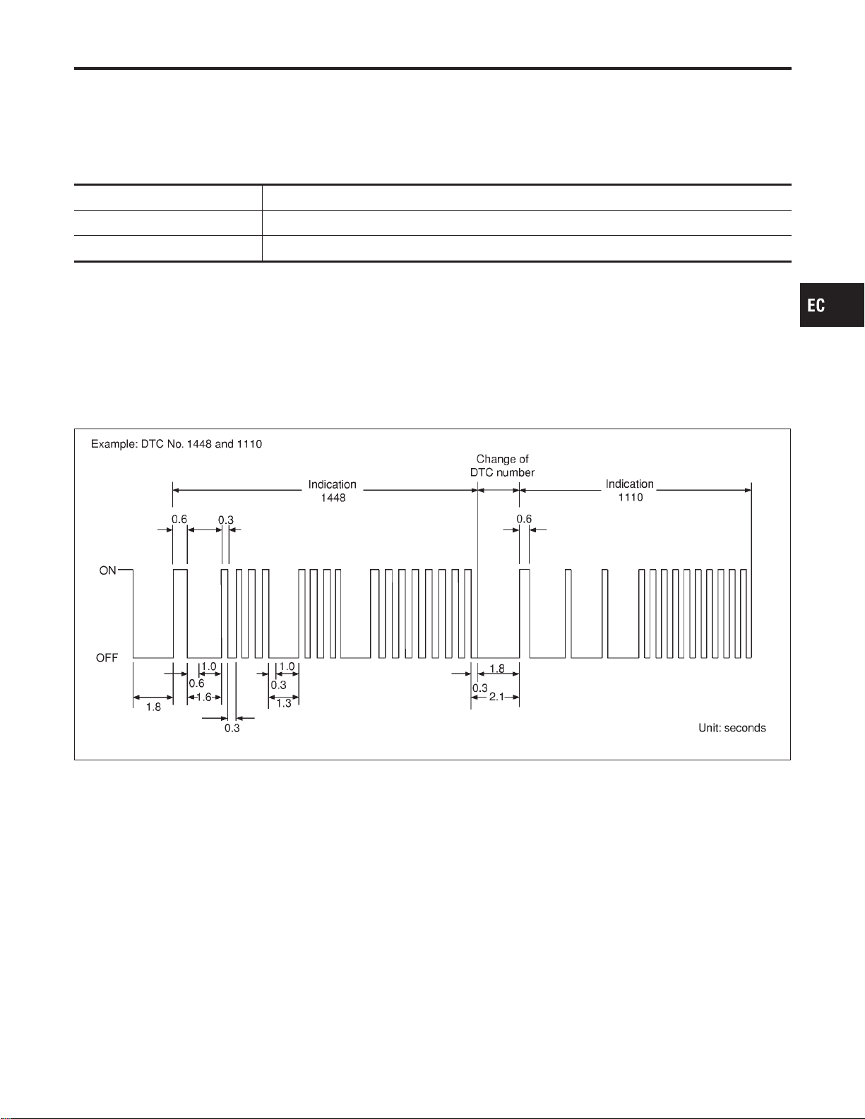
3. Fully release the accelerator pedal, and confirm the DTC 0000 is displayed.
DIAGNOSTIC TEST MODE I — BULB CHECK
NFEC1189S04
In this mode, the MIL on the instrument panel should stay ON. If it remains OFF, check the bulb. Refer to
“WARNING LAMPS”, EL-136 or see DTC P0650 MIL (CIRCUIT), EC-457.
DIAGNOSTIC TEST MODE I — MALFUNCTION WARNING
NFEC1189S05
MIL Condition
ON When the malfunction is detected or the ECM’s CPU is malfunctioning.
OFF No malfunction.
I These DTC numbers are clarified in Diagnostic Test Mode II (SELF-DIAGNOSTIC RESULTS)
DIAGNOSTIC TEST MODE II — SELF-DIAGNOSTIC RESULTS
NFEC1189S06
In this mode, the DTC and 1st trip DTC are indicated by the number of blinks of the MIL as shown below.
The DTC and 1st trip DTC are displayed at the same time. If the MIL does not illuminate in diagnostic test
mode I (Malfunction warning), all displayed items are 1st trip DTCs. If only one code is displayed when the
MIL illuminates in diagnostic test mode II (SELF-DIAGNOSTIC RESULTS), it is a DTC; if two or more codes
are displayed, they may be either DTCs or 1st trip DTCs. DTC No. is same as that of 1st trip DTC. These
unidentified codes can be identified by using the CONSULT-II or GST. A DTC will be used as an example for
how to read a code.
SEF952W
A particular trouble code can be identified by the number of four-digit numeral flashes. The “zero” is indicated
by the number of ten flashes. The length of time the 1,000th-digit numeral flashes on and off is 1.2 seconds
consisting of an ON (0.6-second) - OFF (0.6-second) cycle.
The 100th-digit numeral and lower digit numerals consist of a 0.3-second ON and 0.3-second OFF cycle.
A change from one digit numeral to another occurs at an interval of 1.0-second OFF. In other words, the later
numeral appears on the display 1.3 seconds after the former numeral has disappeared.
A change from one trouble code to another occurs at an interval of 1.8-second OFF.
In this way, all the detected malfunctions are classified by their DTC numbers. The DTC “0000” refers to no
malfunction. (See “TROUBLE DIAGNOSIS — INDEX”, EC-9.)
How to Erase Diagnostic Test Mode II (Self-diagnostic Results)
NFEC1189S0601
The DTC can be erased from the back up memory in the ECM by depressing accelerator pedal. Refer to How
to Switch Diagnostic Test Mode.
I If the battery is disconnected, the DTC will be lost from the backup memory after approx 24 hours.
I Be careful not to erase the stored memory before starting trouble diagnoses.
GI
MA
EM
LC
FE
CL
MT
AT
AX
SU
BR
ST
RS
BT
HA
SC
EL
IDX
ON BOARD DIAGNOSTIC SYSTEM DESCRIPTION
Malfunction Indicator Lamp (MIL) (Cont’d)
EC-95

DIAGNOSTIC TEST MODE II — HEATED OXYGEN SENSOR 1 MONITOR
NFEC1189S07
In this mode, the MIL displays the condition of the fuel mixture (lean or rich) which is monitored by the heated
oxygen sensor 1.
MIL Fuel mixture condition in the exhaust gas Air fuel ratio feedback control condition
ON Lean
Closed loop system
OFF Rich
*Remains ON or OFF Any condition Open loop system
*: Maintains conditions just before switching to open loop.
To check the heated oxygen sensor 1 function, start engine in the Diagnostic Test Mode II and warm it up until
engine coolant temperature indicator points to the middle of the gauge.
Next run engine at about 2,000 rpm for about 2 minutes under no-load conditions. Then make sure that the
MIL comes ON more than 5 times within 10 seconds with engine running at 2,000 rpm under no-load.
OBD System Operation Chart
NFEC0033
RELATIONSHIP BETWEEN MIL, 1ST TRIP DTC, DTC, AND DETECTABLE ITEMS
NFEC0033S01
I When a malfunction is detected for the first time, the 1st trip DTC and the 1st trip freeze frame data are
stored in the ECM memory.
I When the same malfunction is detected in two consecutive trips, the DTC and the freeze frame data are
stored in the ECM memory, and the MIL will come on. For details, refer to “Two Trip Detection Logic” on
EC-75.
I The MIL will go off after the vehicle is driven 3 times with no malfunction. The drive is counted only when
the recorded driving pattern is met (as stored in the ECM). If another malfunction occurs while counting,
the counter will reset.
I The DTC and the freeze frame data will be stored until the vehicle is driven 40 times (driving pattern A)
without the same malfunction recurring (except for Misfire and Fuel Injection System). For Misfire and Fuel
Injection System, the DTC and freeze frame data will be stored until the vehicle is driven 80 times (driv-
ing pattern C) without the same malfunction recurring. The “TIME” in “SELF-DIAGNOSTIC RESULTS”
mode of CONSULT-II will count the number of times the vehicle is driven.
I The 1st trip DTC is not displayed when the self-diagnosis results in “OK” for the 2nd trip.
SUMMARY CHART
NFEC0033S02
Items Fuel Injection System Misfire Other
MIL (goes off) 3 (pattern B) 3 (pattern B) 3 (pattern B)
DTC, Freeze Frame Data (no
display)
80 (pattern C) 80 (pattern C) 40 (pattern A)
1st Trip DTC (clear) 1 (pattern C), *1 1 (pattern C), *1 1 (pattern B)
1st Trip Freeze Frame Data
(clear)
*1, *2 *1, *2 1 (pattern B)
For details about patterns “B” and “C” under “Fuel Injection System” and “Misfire”, see EC-98.
For details about patterns “A” and “B” under “Other”, see EC-100.
*1: Clear timing is at the moment OK is detected.
*2: Clear timing is when the same malfunction is detected in the 2nd trip.
ON BOARD DIAGNOSTIC SYSTEM DESCRIPTION
Malfunction Indicator Lamp (MIL) (Cont’d)
EC-96
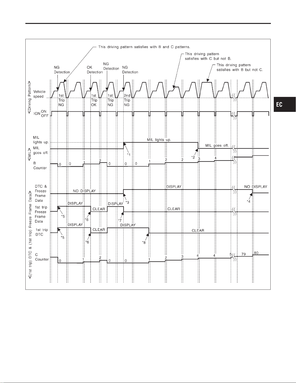
RELATIONSHIP BETWEEN MIL, DTC, 1ST TRIP DTC AND DRIVING PATTERNS FOR
“MISFIRE” <EXHAUST QUALITY DETERIORATION>, “FUEL INJECTION SYSTEM”
=NFEC0033S03
SEF392S
*1: When the same malfunction is
detected in two consecutive trips,
MIL will light up.
*2: MIL will go off after vehicle is
driven 3 times (pattern B) without
any malfunctions.
*3: When the same malfunction is
detected in two consecutive trips,
the DTC and the freeze frame
data will be stored in ECM.
*4: The DTC and the freeze frame
data will not be displayed any
longer after vehicle is driven 80
times (pattern C) without the same
malfunction. (The DTC and the
freeze frame data still remain in
ECM.)
*5: When a malfunction is detected
for the first time, the 1st trip DTC
and the 1st trip freeze frame data
will be stored in ECM.
*6: The 1st trip DTC and the 1st trip
freeze frame data will be cleared
at the moment OK is detected.
*7: When the same malfunction is
detected in the 2nd trip, the 1st
trip freeze frame data will be
cleared.
*8: 1st trip DTC will be cleared when
vehicle is driven once (pattern C)
without the same malfunction after
DTC is stored in ECM.
GI
MA
EM
LC
FE
CL
MT
AT
AX
SU
BR
ST
RS
BT
HA
SC
EL
IDX
ON BOARD DIAGNOSTIC SYSTEM DESCRIPTION
OBD System Operation Chart (Cont’d)
EC-97

EXPLANATION FOR DRIVING PATTERNS FOR “MISFIRE <EXHAUST QUALITY
DETERIORATION>”, “FUEL INJECTION SYSTEM”
NFEC0033S04
<Driving Pattern B>
NFEC0033S0401
Driving pattern B means the vehicle operation as follows:
All components and systems should be monitored at least once by the OBD system.
I The B counter will be cleared when the malfunction is detected once regardless of the driving pattern.
I The B counter will be counted up when driving pattern B is satisfied without any malfunction.
I The MIL will go off when the B counter reaches 3. (*2 in “OBD SYSTEM OPERATION CHART”)
<Driving Pattern C>
NFEC0033S0402
Driving pattern C means the vehicle operation as follows:
1) The following conditions should be satisfied at the same time:
Engine speed: (Engine speed in the freeze frame data) ±375 rpm
Calculated load value: (Calculated load value in the freeze frame data) x (1±0.1) [%]
Engine coolant temperature (T) condition:
I When the freeze frame data shows lower than 70°C (158°F), “T” should be lower than 70°C (158°F).
I When the freeze frame data shows higher than or equal to 70°C (158°F), “T” should be higher than or
equal to 70°C (158°F).
Example:
If the stored freeze frame data is as follows:
Engine speed: 850 rpm, Calculated load value: 30%, Engine coolant temperature: 80°C (176°F)
To be satisfied with driving pattern C, the vehicle should run under the following conditions:
Engine speed: 475 - 1,225 rpm, Calculated load value: 27 - 33%, Engine coolant temperature: more than 70°C
(158°F)
I The C counter will be cleared when the malfunction is detected regardless of (1).
I The C counter will be counted up when (1) is satisfied without the same malfunction.
I The DTC will not be displayed after C counter reaches 80.
I The 1st trip DTC will be cleared when C counter is counted once without the same malfunction after DTC
is stored in ECM.
ON BOARD DIAGNOSTIC SYSTEM DESCRIPTION
OBD System Operation Chart (Cont’d)
EC-98
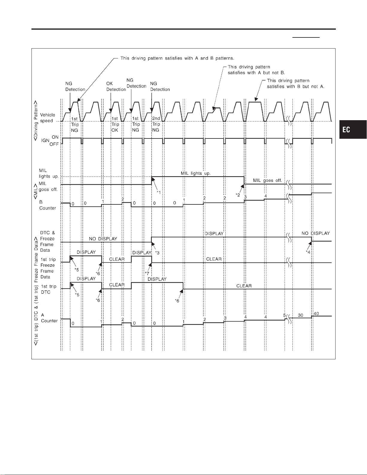
RELATIONSHIP BETWEEN MIL, DTC, 1ST TRIP DTC AND DRIVING PATTERNS EXCEPT
FOR “MISFIRE <EXHAUST QUALITY DETERIORATION>”, “FUEL INJECTION SYSTEM”
NFEC0033S05
SEF393S
*1: When the same malfunction is
detected in two consecutive trips,
MIL will light up.
*2: MIL will go off after vehicle is
driven 3 times (pattern B) without
any malfunctions.
*3: When the same malfunction is
detected in two consecutive trips,
the DTC and the freeze frame
data will be stored in ECM.
*4: The DTC and the freeze frame
data will not be displayed any
longer after vehicle is driven 40
times (pattern A) without the same
malfunction.
(The DTC and the freeze frame
data still remain in ECM.)
*5: When a malfunction is detected
for the first time, the 1st trip DTC
and the 1st trip freeze frame data
will be stored in ECM.
*6: 1st trip DTC will be cleared after
vehicle is driven once (pattern B)
without the same malfunction.
*7: When the same malfunction is
detected in the 2nd trip, the 1st
trip freeze frame data will be
cleared.
GI
MA
EM
LC
FE
CL
MT
AT
AX
SU
BR
ST
RS
BT
HA
SC
EL
IDX
ON BOARD DIAGNOSTIC SYSTEM DESCRIPTION
OBD System Operation Chart (Cont’d)
EC-99
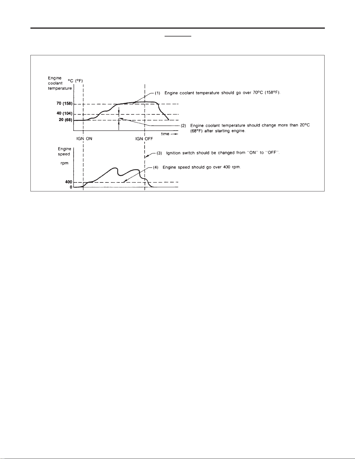
EXPLANATION FOR DRIVING PATTERNS EXCEPT FOR “MISFIRE <EXHAUST QUALITY
DETERIORATION>”, “FUEL INJECTION SYSTEM”
NFEC0033S06
<Driving Pattern A>
NFEC0033S0601
AEC574
I The A counter will be cleared when the malfunction is detected regardless of (1) - (4).
I The A counter will be counted up when (1) - (4) are satisfied without the same malfunction.
I The DTC will not be displayed after the A counter reaches 40.
<Driving Pattern B>
NFEC0033S0602
Driving pattern B means the vehicle operation as follows:
All components and systems should be monitored at least once by the OBD system.
I The B counter will be cleared when the malfunction is detected once regardless of the driving pattern.
I The B counter will be counted up when driving pattern B is satisfied without any malfunctions.
I The MIL will go off when the B counter reaches 3 (*2 in “OBD System Operation Chart”, EC-96).
ON BOARD DIAGNOSTIC SYSTEM DESCRIPTION
OBD System Operation Chart (Cont’d)
EC-100
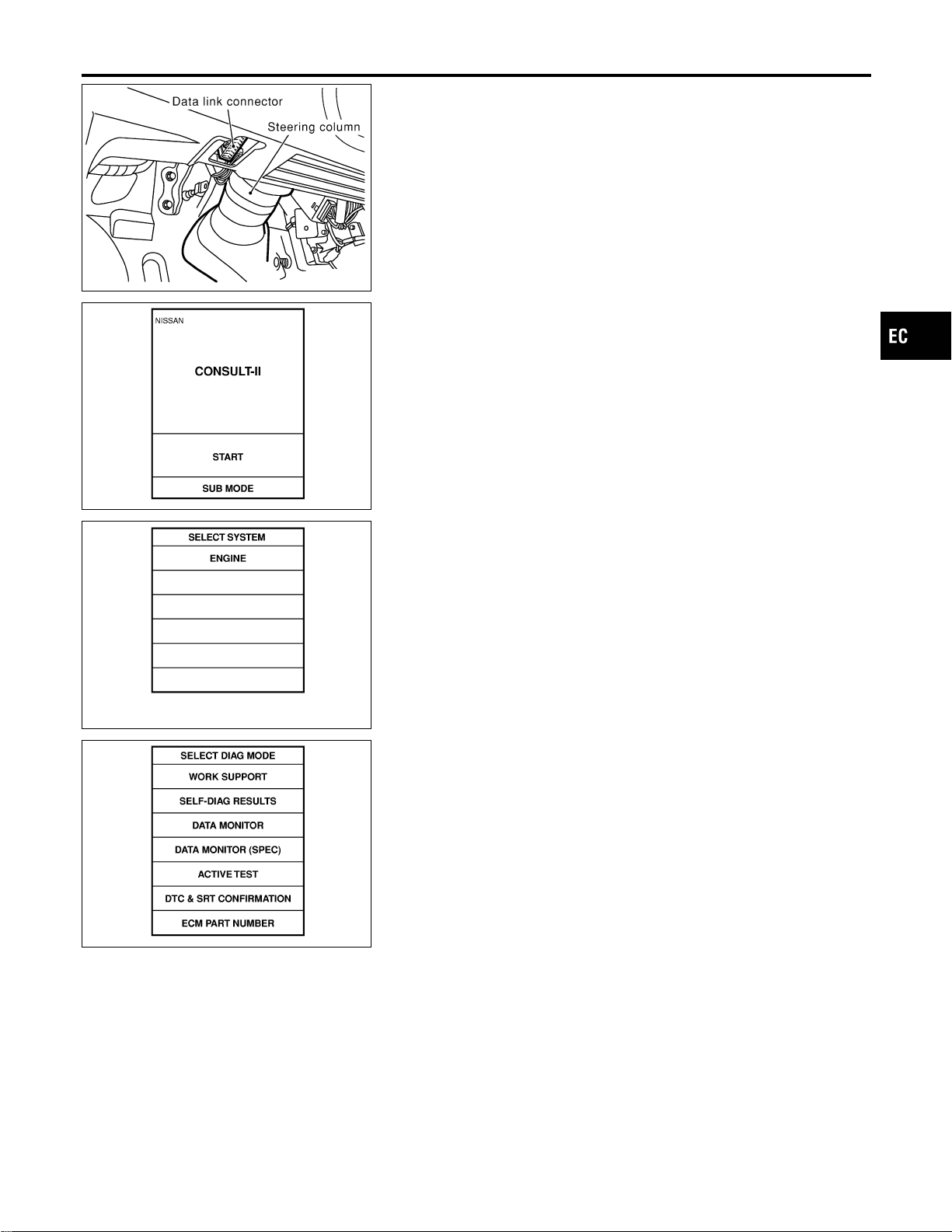
SEF289X
CONSULT-II
=NFEC0034
CONSULT-II INSPECTION PROCEDURE
NFEC0034S01
1. Turn ignition switch OFF.
2. Connect CONSULT-II to data link connector, which is located
under LH dash panel near the fuse box cover.
PBR455D
3. Turn ignition switch ON.
4. Touch “START”.
SEF948Y
5. Touch “ENGINE”.
SEF824Y
6. Perform each diagnostic test mode according to each service
procedure.
For further information, see the CONSULT-II Operation
Manual.
GI
MA
EM
LC
FE
CL
MT
AT
AX
SU
BR
ST
RS
BT
HA
SC
EL
IDX
ON BOARD DIAGNOSTIC SYSTEM DESCRIPTION
CONSULT-II
EC-101

ENGINE CONTROL COMPONENT PARTS/CONTROL
SYSTEMS APPLICATION
NFEC0034S02
Item
DIAGNOSTIC TEST MODE
WORK
SUP-
PORT
SELF-DIAGNOSTIC
RESULTS
DATA
MONI-
TOR
DATA
MONI-
TOR
(SPEC)
ACTIVE
TEST
DTC & SRT
CONFIRMATION
DTC*1
FREEZE
FRAME
DATA*2
SRT
STATUS
DTC
WORK
SUP-
PORT
ENGINE CONTROL COMPONENT PARTS
INPUT
Crankshaft position sensor
(POS)
XXXX
Camshaft position sensor
(PHASE)
X
Mass air flow sensor X X X
Engine coolant temperature sen-
sor
XXXXX
Heated oxygen sensor 1 X X X X X
Heated oxygen sensor 2 X X X X X
Vehicle speed sensor XXXX
Accelerator pedal position sensor X X X
Throttle position sensor X X X
Fuel tank temperature sensor X X X X
EVAP control system pressure
sensor
XXX
Absolute pressure sensor X X X
Intake air temperature sensor X X X
Knock sensor X
Refrigerant pressure sensor X X
Ignition switch (start signal) X X
Closed throttle position switch
(accelerator pedal position sen-
sor signal)
XX
Air conditioner switch X X
Park/neutral position (PNP)
switch
XXX
Power steering pressure sensor X X X
Battery voltage X X
Load signal X X
Fuel level sensor X X X
ASCD steering switch X X X
ASCD brake switch X X X
ON BOARD DIAGNOSTIC SYSTEM DESCRIPTION
CONSULT-II (Cont’d)
EC-102
Item
DIAGNOSTIC TEST MODE
WORK
SUP-
PORT
SELF-DIAGNOSTIC
RESULTS
DATA
MONI-
TOR
DATA
MONI-
TOR
(SPEC)
ACTIVE
TEST
DTC & SRT
CONFIRMATION
DTC*1
FREEZE
FRAME
DATA*2
SRT
STATUS
DTC
WORK
SUP-
PORT
ENGINE CONTROL COMPONENT PARTS
OUTPUT
Injectors X X X
Power transistor (Ignition timing) X X X
Throttle control motor relay X X X
EVAP canister purge volume
control solenoid valve
X XXX X
Air conditioner relay X X
Fuel pump relay X X X X
Heated oxygen sensor 1 heater X X X X
Heated oxygen sensor 2 heater X X X X
EVAP canister vent control valve X X X X
Vacuum cut valve bypass valve X X X X X
VIAS control solenoid valve X X X X
Intake valve timing control sole-
noid valve
X XXX
Electronic controlled engine
mount
XXX
Calculated load value X X X
X: Applicable
*1: This item includes 1st trip DTCs.
*2: This mode includes 1st trip freeze frame data or freeze frame data. The items appear on CONSULT-II screen in freeze frame data
mode only if a 1st trip DTC or DTC is detected. For details, refer to EC-77.
GI
MA
EM
LC
FE
CL
MT
AT
AX
SU
BR
ST
RS
BT
HA
SC
EL
IDX
ON BOARD DIAGNOSTIC SYSTEM DESCRIPTION
CONSULT-II (Cont’d)
EC-103

FUNCTION
=NFEC0034S03
Diagnostic test mode Function
WORK SUPPORT
This mode enables a technician to adjust some devices faster and more accurately by following the
indications on the CONSULT-II unit.
SELF-DIAG RESULTS
Self-diagnostic results such as 1st trip DTC, DTCs and 1st trip freeze frame data or freeze frame
data can be read and erased quickly.*1
DATA MONITOR Input/Output data in the ECM can be read.
DATA MONITOR (SPEC)
Input/Output specification of the basic fuel schedule, AFM, A/F feedback control value and the
other data monitor items can be read.
ACTIVE TEST
Diagnostic Test Mode in which CONSULT-II drives some actuators apart from the ECMs and also
shifts some parameters in a specified range.
FUNCTION TEST
Conducted by CONSULT-II instead of a technician to determine whether each system is “OK” or
“NG”.
DTC & SRT CONFIRMA-
TION
The status of system monitoring tests and the self-diagnosis status/result can be confirmed.
ECM PART NUMBER ECM part number can be read.
*1 The following emission-related diagnostic information is cleared when the ECM memory is erased.
1) Diagnostic trouble codes
2) 1st trip diagnostic trouble codes
3) Freeze frame data
4) 1st trip freeze frame data
5) System readiness test (SRT) codes
6) Test values
7) Others
ON BOARD DIAGNOSTIC SYSTEM DESCRIPTION
CONSULT-II (Cont’d)
EC-104

WORK SUPPORT MODE
=NFEC0034S04
WORK ITEM CONDITION USAGE
FUEL PRESSURE RELEASE I FUEL PUMP WILL STOP BY TOUCHING “START”
DURING IDLING.
CRANK A FEW TIMES AFTER ENGINE STALLS.
When releasing fuel pressure
from fuel line
IDLE AIR VOL LEARN I THE IDLE AIR VOLUME THAT KEEPS THE ENGINE
WITHIN THE SPECIFIED RANGE IS MEMORIZED IN
ECM.
When learning the idle air volume
SELF-LEARNING CONT I THE COEFFICIENT OF SELF-LEARNING CONTROL
MIXTURE RATIO RETURNS TO THE ORIGINAL
COEFFICIENT.
When clearing the coefficient of
self-learning control value
EVAP SYSTEM CLOSE OPEN THE VACUUM CUT VALVE BYPASS VALVE AND
CLOSE THE EVAP CANISTER VENT CONTROL VALVE
IN ORDER TO MAKE EVAP SYSTEM CLOSE UNDER
THE FOLLOWING CONDITIONS.
I IGN SW “ON”
I ENGINE NOT RUNNING
I AMBIENT TEMPERATURE IS ABOVE 0°C (32°F).
I NO VACUUM AND NO HIGH PRESSURE IN EVAP
SYSTEM
I TANK FUEL TEMP. IS MORE THAN 0°C (32°F).
I WITHIN 10 MINUTES AFTER STARTING “EVAP SYS-
TEM CLOSE”
I WHEN TRYING TO EXECUTE “EVAP SYSTEM
CLOSE” UNDER THE CONDITION EXCEPT ABOVE,
CONSULT-II WILL DISCONTINUE IT AND DISPLAY
APPROPRIATE INSTRUCTION.
NOTE:
WHEN STARTING ENGINE, CONSULT-II MAY DIS-
PLAY “BATTERY VOLTAGE IS LOW. CHARGE
BATTERY”, EVEN IN USING CHARGED BATTERY.
When detecting EVAP vapor leak
point of EVAP system
TARGET IGN TIM ADJ* I IDLE CONDITION I When adjusting target ignition
timing
After adjustment, confirm target
ignition timing with a timing
light.
I If once the “TARGET IDLE
RPM ADJ” has been done, the
Idle Air Volume Learning proce-
dure will not be completed.
TARGET IDLE RPM ADJ* I IDLE CONDITION When setting target idle speed
*: This function is not necessary in the usual service procedure.
SELF-DIAGNOSTIC MODE
NFEC0034S05
DTC and 1st Trip DTC
NFEC0034S0501
Regarding items of “DTC and 1st trip DTC”, refer to “TROUBLE
DIAGNOSIS — INDEX” (See EC-9.)
Freeze Frame Data and 1st Trip Freeze Frame Data
NFEC0034S0502
Freeze frame data
item*1
Description
DIAG TROUBLE
CODE
[PXXXX]
I The engine control component part/control system has a trouble code, it is displayed as “PXXXX”.
(Refer to “TROUBLE DIAGNOSIS — INDEX”, EC-9.)
GI
MA
EM
LC
FE
CL
MT
AT
AX
SU
BR
ST
RS
BT
HA
SC
EL
IDX
ON BOARD DIAGNOSTIC SYSTEM DESCRIPTION
CONSULT-II (Cont’d)
EC-105

Freeze frame data
item*1
Description
FUEL SYS-B1*2
I “Fuel injection system status” at the moment a malfunction is detected is displayed.
I One mode in the following is displayed.
“MODE 2”: Open loop due to detected system malfunction
“MODE 3”: Open loop due to driving conditions (power enrichment, deceleration enrichment)
“MODE 4”: Closed loop - using oxygen sensor(s) as feedback for fuel control
“MODE 5”: Open loop - has not yet satisfied condition to go to closed loop
FUEL SYS-B2*2
CAL/LD VALUE [%] I The calculated load value at the moment a malfunction is detected is displayed.
COOLANT TEMP [°C]
or [°F]
I The engine coolant temperature at the moment a malfunction is detected is displayed.
S-FUEL TRIM-B1 [%]
I “Short-term fuel trim” at the moment a malfunction is detected is displayed.
I The short-term fuel trim indicates dynamic or instantaneous feedback compensation to the base fuel
schedule.
S-FUEL TRIM-B2 [%]
L-FUEL TRIM-B1 [%]
I “Long-term fuel trim” at the moment a malfunction is detected is displayed.
I The long-term fuel trim indicates much more gradual feedback compensation to the base fuel schedule
than short-term fuel trim.
L-FUEL TRIM-B2 [%]
ENGINE SPEED
[rpm]
I The engine speed at the moment a malfunction is detected is displayed.
VHCL SPEED [km/h]
or [mph]
I The vehicle speed at the moment a malfunction is detected is displayed.
B/FUEL SCHDL
[msec]
I The base fuel schedule at the moment a malfunction is detected is displayed.
INT/A TEMP SE [°C]
or [°F]
I The intake air temperature at the moment a malfunction is detected is displayed.
*1: The items are the same as those of 1st trip freeze frame data.
*2: Regarding A33, “B1” indicates bank 1 and “B2” indicates bank 2.
ON BOARD DIAGNOSTIC SYSTEM DESCRIPTION
CONSULT-II (Cont’d)
EC-106
DATA MONITOR MODE
=NFEC0034S06
Monitored item
[Unit]
ECM
INPUT
SIG-
NALS
MAIN
SIG-
NALS
CAN
DIAG
SUP-
PORT
MNTR
Description Remarks
ENG SPEED [rpm] qq
I Indicates the engine speed com-
puted from the signal of the crank-
shaft position sensor (POS) and
camshaft position sensor (PHASE)
I Accuracy becomes poor if engine
speed drops below the idle rpm.
I If the signal is interrupted while the
engine is running, an abnormal
value may be indicated.
MAS A/F SE-B1 [V] qq
I The signal voltage of the mass air
flow sensor is displayed.
I When the engine is stopped, a cer-
tain value is indicated.
COOLAN TEMP/S
[°C] or [°F]
qq
I The engine coolant temperature
(determined by the signal voltage of
the engine coolant temperature
sensor) is displayed.
I When the engine coolant tempera-
ture sensor is open or short-
circuited, ECM enters fail-safe
mode. The engine coolant tempera-
ture determined by the ECM is dis-
played.
HO2S1 (B1) [V] qq
I The signal voltage of the heated
oxygen sensor 1 is displayed.
HO2S1 (B2) [V] q
HO2S2 (B1) [V] q
I The signal voltage of the heated
oxygen sensor 2 is displayed.
HO2S2 (B2) [V] q
HO2S1 MNTR (B1)
[RICH/LEAN]
qq
I Display of heated oxygen sensor 1
signal during air-fuel ratio feedback
control:
RICH ... means the mixture became
“rich”, and control is being affected
toward a leaner mixture.
LEAN ... means the mixture
became “lean”, and control is being
affected toward a rich mixture.
I After turning ON the ignition switch,
“RICH” is displayed until air-fuel
mixture ratio feedback control
begins.
I When the air-fuel ratio feedback is
clamped, the value just before the
clamping is displayed continuously.
HO2S1 MNTR (B2)
[RICH/LEAN]
q
HO2S2 MNTR (B1)
[RICH/LEAN]
q
I Display of heated oxygen sensor 2
signal:
RICH ... means the amount of oxy-
gen after three way catalyst is rela-
tively small.
LEAN ... means the amount of oxy-
gen after three way catalyst is rela-
tively large.
I When the engine is stopped, a cer-
tain value is indicated.
HO2S2 MNTR (B2)
[RICH/LEAN]
q
VHCL SPEED SE
[km/h] or [mph]
qq
I The vehicle speed computed from
the vehicle speed sensor signal is
displayed.
BATTERY VOLT [V] qq
I The power supply voltage of ECM
is displayed.
ACCEL SEN 1 [V] qq
I The accelerator pedal position sen-
sor signal voltage is displayed.
ACCEL SEN 2 [V] q
THRTL SEN 1 [V] qq
I The throttle position sensor signal
voltage is displayed.
THRTL SEN 2 [V] q
FUEL T/TMP SE
[°C] or [°F]
q
I The fuel temperature judged from
the fuel tank temperature sensor
signal voltage is displayed.
GI
MA
EM
LC
FE
CL
MT
AT
AX
SU
BR
ST
RS
BT
HA
SC
EL
IDX
ON BOARD DIAGNOSTIC SYSTEM DESCRIPTION
CONSULT-II (Cont’d)
EC-107

Monitored item
[Unit]
ECM
INPUT
SIG-
NALS
MAIN
SIG-
NALS
CAN
DIAG
SUP-
PORT
MNTR
Description Remarks
INT/A TEMP SE
[°C] or [°F]
qq
I The intake air temperature deter-
mined by the signal voltage of the
intake air temperature sensor is
indicated.
EVAP SYS PRES
[V]
q
I The signal voltage of EVAP control
system pressure sensor is dis-
played.
ABSOL PRES/SE
[V]
q
I The signal voltage of the absolute
pressure sensor is displayed.
FUEL LEVEL SE
[V]
q
I The signal voltage of the fuel level
sensor is displayed.
START SIGNAL
[ON/OFF]
qq
I Indicates [ON/OFF] condition from
the starter signal.
I After starting the engine, [OFF] is
displayed regardless of the starter
signal.
CLSD THL POS
[ON/OFF]
qq
I Indicates idle position [ON/OFF]
computed by ECM according to the
accelerator pedal position sensor
signal.
AIR COND SIG
[ON/OFF]
qq
I Indicates [ON/OFF] condition of the
air conditioner switch as determined
by the air conditioner signal.
P/N POSI SW
[ON/OFF]
qq
I Indicates [ON/OFF] condition from
the park/neutral position (PNP)
switch signal.
PW/ST SIGNAL
[ON/OFF]
qq
I [ON/OFF] condition of the power
steering system (determined by the
power steering pressure sensor sig-
nal) is indicated.
LOAD SIGNAL
[ON/OFF]
qq
I Indicates [ON/OFF] condition from
the electrical load signal and/or
lighting switch.
ON ... rear defogger is operating
and/or lighting switch is on.
OFF ... rear defogger is not operat-
ing and lighting switch is not on.
IGNITION SW
[ON/OFF]
q
I Indicates [ON/OFF] condition from
ignition switch.
BRAKE SW
[ON/OFF]
I Indicates [ON/OFF] condition from
the stop lamp switch signal.
INJ PULSE-B1
[msec]
q
I Indicates the actual fuel injection
pulse width compensated by ECM
according to the input signals.
I When the engine is stopped, a cer-
tain computed value is indicated.
INJ PULSE-B2
[msec]
B/FUEL SCHDL
[msec]
q
I “Base fuel schedule” indicates the
fuel injection pulse width pro-
grammed into ECM, prior to any
learned on board correction.
ON BOARD DIAGNOSTIC SYSTEM DESCRIPTION
CONSULT-II (Cont’d)
EC-108
Monitored item
[Unit]
ECM
INPUT
SIG-
NALS
MAIN
SIG-
NALS
CAN
DIAG
SUP-
PORT
MNTR
Description Remarks
IGN TIMING
[BTDC]
q
I Indicates the ignition timing com-
puted by ECM according to the
input signals.
I When the engine is stopped, a cer-
tain value is indicated.
PURG VOL C/V [%]
I Indicates the EVAP canister purge
volume control solenoid valve con-
trol value computed by the ECM
according to the input signals.
I The opening becomes larger as the
value increases.
A/F ALPHA-B1 [%] q
I The mean value of the air-fuel ratio
feedback correction factor per cycle
is indicated.
I When the engine is stopped, a cer-
tain value is indicated.
I This data also includes the data for
the air-fuel ratio learning control.
A/F ALPHA-B2 [%] q
AIR COND RLY
[ON/OFF]
q
I The air conditioner relay control
condition (determined by ECM
according to the input signal) is
indicated.
FUEL PUMP RLY
[ON/OFF]
q
I Indicates the fuel pump relay con-
trol condition determined by ECM
according to the input signals.
VENT CONT/V
[ON/OFF]
I The control condition of the EVAP
canister vent control valve (deter-
mined by ECM according to the
input signal) is indicated.
I ON ... Closed
OFF ... Open
HO2S1 HTR (B1)
[ON/OFF]
I Indicates [ON/OFF] condition of
heated oxygen sensor 1 heater
determined by ECM according to
the input signals.
HO2S1 HTR (B2)
[ON/OFF]
HO2S2 HTR (B1)
[ON/OFF]
I Indicates [ON/OFF] condition of
heated oxygen sensor 2 heater
determined by ECM according to
the input signals.
HO2S2 HTR (B2)
[ON/OFF]
VC/V BYPASS/V
[ON/OFF]
I The control condition of the vacuum
cut valve bypass valve (determined
by ECM according to the input sig-
nal) is indicated.
I ON ... Open
OFF ... Closed
CAL/LD VALUE [%]
I “Calculated load value” indicates
the value of the current airflow
divided by peak airflow.
MASS AIRFLOW
[g·m/s]
I Indicates the mass airflow com-
puted by ECM according to the sig-
nal voltage of the mass airflow sen-
sor.
GI
MA
EM
LC
FE
CL
MT
AT
AX
SU
BR
ST
RS
BT
HA
SC
EL
IDX
ON BOARD DIAGNOSTIC SYSTEM DESCRIPTION
CONSULT-II (Cont’d)
EC-109

Monitored item
[Unit]
ECM
INPUT
SIG-
NALS
MAIN
SIG-
NALS
CAN
DIAG
SUP-
PORT
MNTR
Description Remarks
INT/V TIM (B1)
[°CA]
I Indicate [°CA] of intake camshaft
advanced angle.
INT/V TIM (B2)
[°CA]
INT/V SOL (B1) [%]
I The control condition of the intake
valve timing control solenoid valve
is indicated.
INT/V SOL (B2) [%]
TRVL AFTER MIL
[km] or [Mile]
I Distance traveled while MIL is acti-
vated
VIAS S/V
[ON/OFF]
I The control condition of the VIAS
control solenoid valve (determined
by ECM according to the input sig-
nal) is indicated.
I OFF ... VIAS control solenoid valve
is not operating.
ON ... VIAS control solenoid valve
is operating.
IDL A/V LEARN
I Display the condition of idle air vol-
ume learning
YET ... Idle air volume learning has
not been performed yet.
CMPLT ... Idle air volume learning
has already been performed suc-
cessfully.
INCMP ... Idle air volume learning
has not been performed success-
fully.
ENGINE MOUNT
[IDLE/TRVL]
I The control condition of the elec-
tronic controlled engine mount
(computed by ECM according to
the input signals) is indicated.
I IDLE ... Idle condition
I TRVL ... Driving condition
COOLING FAN
[HI/LOW/OFF]
I Indicates the control condition of
the cooling fan (determined by
ECM according to the input signal).
HIGH ... High speed operation
LOW ... Low speed operation
OFF ... Stop
THRTL RELAY
[ON/OFF]
I Indicates the throttle control motor
relay control condition determined
by the ECM according to the input
signals.
AC PRESS SEN
[V]
I The signal voltage from the refriger-
ant pressure sensor is displayed.
BRAKE SW 1
[ON/OFF]
I Indicates [ON/OFF] condition from
ASCD brake switch signal, and
ASCD clutch switch signal (M/T
models) or park/neutral position
relay signal (A/T models).
BRAKE SW 2
[ON/OFF]
I Indicates [ON/OFF] condition of
stop lamp switch signal.
ON BOARD DIAGNOSTIC SYSTEM DESCRIPTION
CONSULT-II (Cont’d)
EC-110
Monitored item
[Unit]
ECM
INPUT
SIG-
NALS
MAIN
SIG-
NALS
CAN
DIAG
SUP-
PORT
MNTR
Description Remarks
MAIN SW
[ON/OFF]
I Indicates [ON/OFF] condition from
CRUISE switch signal.
CANCEL SW
[ON/OFF]
I Indicates [ON/OFF] condition from
CANCEL switch signal.
RESUME/ACC SW
[ON/OFF]
I Indicates [ON/OFF] condition from
ACCEL/RES switch signal.
SET SW
[ON/OFF]
I Indicates [ON/OFF] condition from
COAST/SET switch signal.
VHCL SPEED SE
[km/h] or [mph]
I The present vehicle speed com-
puted from the vehicle speed signal
sent from combination meter is dis-
played.
SET VHCL SPD
[km/h] or [mph]
I The preset vehicle speed is dis-
played.
VHCL SPD CUT
[NON/CUT]
I Indicates the vehicle cruise condi-
tion.
NON...Vehicle speed is maintained
at the ASCD set speed.
CUT...Vehicle speed decreased to
excessively low compared with the
ASCD set speed, and ASCD opera-
tion is cut off.
LO SPEED CUT
[NON/CUT]
I Indicates the vehicle cruise condi-
tion.
NON...Vehicle speed is maintained
at the ASCD set speed.
CUT...Vehicle speed decreased to
excessively low compared with the
ASCD set speed, and ASCD opera-
tion is cut off.
AT OD MONITOR
[ON/OFF]
I Indicates [ON/OFF] condition of A/T
O/D according to the input signal
from the TCM.
AT OD CANCEL]
[ON/OFF]
I Indicates [ON/OFF] condition of A/T
OD cancel signal sent from the
TCM.
CRUISE LAMP
[ON/OFF]
I Indicates [ON/OFF] condition
CRUISE lamp determined by the
ECM according to the input signals.
SET LAMP
[ON/OFF]
I Indicates [ON/OFF] condition of
SET lamp determined by the ECM
according to the input signals.
GI
MA
EM
LC
FE
CL
MT
AT
AX
SU
BR
ST
RS
BT
HA
SC
EL
IDX
ON BOARD DIAGNOSTIC SYSTEM DESCRIPTION
CONSULT-II (Cont’d)
EC-111

Monitored item
[Unit]
ECM
INPUT
SIG-
NALS
MAIN
SIG-
NALS
CAN
DIAG
SUP-
PORT
MNTR
Description Remarks
Voltage [V]
I Voltage, frequency, duty cycle or
pulse width measured by the probe.
I Pulse width, frequency or duty
cycle measured by the pulse probe.
Only ″#″ is displayed if item is
unable to be measured.
I Figures with ″#″s are temporary
ones. They are the same figures as
an actual piece of data which was
just previously measured.
Frequency [msec],
[Hz] or [%]
DUTY-HI
DUTY-LOW
PLS WIDTH-HI
PLS WIDTH-low
CAN COMM
[OK/NG]
q
I Indicates the communication condi-
tion of CAN communication line.
CAN CIRC 1
[OK/UNKWN]
q
CAN CIRC 2
[OK/UNKWN]
q
CAN CIRC 3
[OK/UNKWN]
q
NOTE:
I Any monitored item that does not match the vehicle being diagnosed is deleted from the display automatically.
I Regarding A33 model, “B1” indicates bank 1 and “B2” indicates bank 2.
I Bank 1 (B1) includes No. 1 cylinder.
DATA MONITOR (SPEC) MODE
NFEC0034S11
Monitored item [Unit]
ECM
input
signals
Main
signals
Description Remarks
MAS A/F SE-B1 [V] qq
I The signal voltage of the mass air flow sen-
sor specification is displayed.
I When the engine is running, specifi-
cation range is indicated.
B/FUEL SCHDL
[msec]
I “Base fuel schedule” indicates the fuel injec-
tion pulse width programmed into ECM,
prior to any learned on board correction.
I When the engine is running, specifi-
cation range is indicated.
A/F ALPHA-B1 [%] q
I Indicates the mean value of the air-fuel ratio
feedback correction factor per cycle.
I When the engine is running, specifi-
cation range is indicated.
I This data also includes the data for
the air-fuel ratio learning control.
A/F ALPHA-B2 [%] q
NOTE:
I Any monitored item that does not match the vehicle being diagnosed is deleted from the display automatically.
I Regarding A33 model, “B1” indicates bank 1 and “B2” indicates bank 2.
ACTIVE TEST MODE
NFEC0034S07
TEST ITEM CONDITION JUDGEMENT CHECK ITEM (REMEDY)
FUEL INJECTION
I Engine: Return to the original
trouble condition
I Change the amount of fuel injec-
tion using CONSULT-II.
If trouble symptom disappears, see
CHECK ITEM.
I Harness and connector
I Fuel injectors
I Heated oxygen sensor
ON BOARD DIAGNOSTIC SYSTEM DESCRIPTION
CONSULT-II (Cont’d)
EC-112
TEST ITEM CONDITION JUDGEMENT CHECK ITEM (REMEDY)
IGNITION TIMING
I Engine: Return to the original
trouble condition
I Timing light: Set
I Retard the ignition timing using
CONSULT-II.
If trouble symptom disappears, see
CHECK ITEM.
I Adjust initial ignition timing
POWER BAL-
ANCE
I Engine: After warming up, idle
the engine.
I A/C switch “OFF”
I Shift lever “N”
I Cut off each injector signal one
at a time using CONSULT-II.
Engine runs rough or dies.
I Harness and connector
I Compression
I Injectors
I Power transistor
I Spark plugs
I Ignition coils
COOLING FAN
I Ignition switch: ON
I Turn the cooling fan “ON” and
“OFF” using CONSULT-II.
Cooling fan moves and stops.
I Harness and connector
I Cooling fan motor
I Cooling fan relay
ENG COOLANT
TEMP
I Engine: Return to the original
trouble condition
I Change the engine coolant tem-
perature using CONSULT-II.
If trouble symptom disappears, see
CHECK ITEM.
I Harness and connector
I Engine coolant temperature sen-
sor
I Fuel injectors
FUEL PUMP
RELAY
I Ignition switch: ON
(Engine stopped)
I Turn the fuel pump relay “ON”
and “OFF” using CONSULT-II
and listen to operating sound.
Fuel pump relay makes the operat-
ing sound.
I Harness and connector
I Fuel pump relay
VIAS SOL VALVE
I Ignition switch: ON
I Turn solenoid valve “ON” and
“OFF” with CONSULT-II and lis-
ten for operating sound.
Solenoid valve makes an operating
sound.
I Harness and connector
I Solenoid valve
ENGINE MOUNT-
ING
I Engine: After warming up, run
engine at idle speed.
I Gear position: “D”’ range
(Vehicle stopped)
I Turn electronic controlled engine
mount “IDLE” and “TRVL” with
the CONSULT-II.
Body vibration changes according
to the electronic controlled engine
mount condition.
I Harness and connector
I Electronic controlled engine
mount
PURG VOL
CONT/V
I Engine: After warming up, run
engine at 1,500 rpm.
I Change the EVAP canister purge
volume control solenoid valve
opening percent using CON-
SULT-II.
Engine speed changes according
to the opening percent.
I Harness and connector
I Solenoid valve
FUEL/T TEMP
SEN
I Change the fuel tank temperature using CONSULT-II.
VENT
CONTROL/V
I Ignition switch: ON
(Engine stopped)
I Turn solenoid valve “ON” and
“OFF” with the CONSULT-II and
listen to operating sound.
Solenoid valve makes an operating
sound.
I Harness and connector
I Solenoid valve
VC/V BYPASS/V
I Ignition switch: ON
(Engine stopped)
I Turn solenoid valve “ON” and
“OFF” with the CONSULT-II and
listen to operating sound.
Solenoid valve makes an operating
sound.
I Harness and connector
I Solenoid valve
V/T ASSIGN
ANGLE
I Engine: After warming up, hold
engine speed at 2,500 rpm.
I Change the intake valve timing
using CONSULT-II.
If trouble symptom disappears, see
CHECK ITEM.
I Harness and connector
I Intake valve timing control sole-
noid valve
GI
MA
EM
LC
FE
CL
MT
AT
AX
SU
BR
ST
RS
BT
HA
SC
EL
IDX
ON BOARD DIAGNOSTIC SYSTEM DESCRIPTION
CONSULT-II (Cont’d)
EC-113

DTC & SRT CONFIRMATION MODE
NFEC0034S08
SRT STATUS Mode
NFEC0034S0801
For details, refer to “SYSTEM READINESS TEST (SRT) CODE”,
EC-77.
SRT Work Support Mode
NFEC0034S0803
This mode enables a technician to drive a vehicle to set the SRT
while monitoring the SRT status.
DTC Work Support Mode
NFEC0034S0802
Test mode Test item Condition Reference page
EVAPORATIVE SYSTEM
PURGE FLOW P0441
Refer to corresponding
trouble diagnosis for
DTC.
EC-351
EVP SML LEAK P0442/P1442 EC-361
EVP V/S LEAK P0456/P1456 EC-417
PURG VOL CN/V P1444 EC-573
VC CUT/V BP/V P1491 EC-628
HO2S1
HO2S1 (B1) P0133 EC-228
HO2S1 (B1) P0134 EC-240
HO2S1 (B1) P1143 EC-492
HO2S1 (B1) P1144 EC-499
HO2S1 (B2) P0153 EC-228
HO2S1 (B2) P0154 EC-240
HO2S1 (B2) P1163 EC-492
HO2S1 (B2) P1164 EC-499
HO2S2
HO2S2 (B1) P0139 EC-257
HO2S2 (B1) P1146 EC-506
HO2S2 (B1) P1147 EC-516
HO2S2 (B2) P0159 EC-257
HO2S2 (B2) P1166 EC-506
HO2S2 (B2) P1167 EC-516
ON BOARD DIAGNOSTIC SYSTEM DESCRIPTION
CONSULT-II (Cont’d)
EC-114
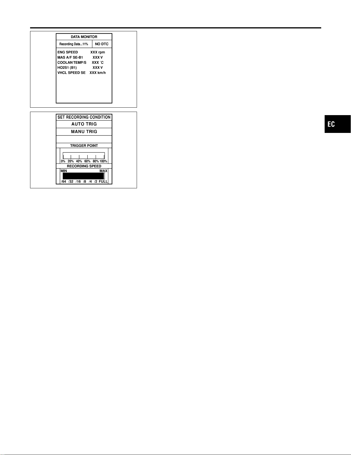
SEF705Y
SEF707X
REAL TIME DIAGNOSIS IN DATA MONITOR MODE
(RECORDING VEHICLE DATA)
NFEC0034S10
CONSULT-II has two kinds of triggers and they can be selected by
touching “SETTING” in “DATA MONITOR” mode.
1) “AUTO TRIG” (Automatic trigger):
I The malfunction will be identified on the CONSULT-II screen in
real time.
In other words, DTC/1st trip DTC and malfunction item will be
displayed if the malfunction is detected by ECM.
At the moment a malfunction is detected by ECM, “MONITOR”
in “DATA MONITOR” screen is changed to “Recording Data ...
xx%” as shown at left, and the data after the malfunction detec-
tion is recorded. Then when the percentage reached 100%,
“REAL-TIME DIAG” screen is displayed. If “STOP” is touched
on the screen during “ Recording Data ... xx%”, “REAL-TIME
DIAG” screen is also displayed.
The recording time after the malfunction detection and the
recording speed can be changed by “TRIGGER POINT” and
“Recording Speed”. Refer to CONSULT-II OPERATION
MANUAL.
2) “MANU TRIG” (Manual trigger):
I DTC/1st trip DTC and malfunction item will not be displayed
automatically on CONSULT-II screen even though a malfunc-
tion is detected by ECM.
DATA MONITOR can be performed continuously even though
a malfunction is detected.
Use these triggers as follows:
1) “AUTO TRIG”
I While trying to detect the DTC/1st trip DTC by performing the
“DTC Confirmation Procedure”, be sure to select to “DATA
MONITOR (AUTO TRIG)” mode. You can confirm the malfunc-
tion at the moment it is detected.
I While narrowing down the possible causes, CONSULT-II
should be set in “DATA MONITOR (AUTO TRIG)” mode, espe-
cially in case the incident is intermittent.
When you are inspecting the circuit by gently shaking (or twist-
ing) the suspicious connectors, components and harness in
the “DTC Confirmation Procedure”, the moment a malfunction
is found theDTC/1st tripDTC will bedisplayed. (Refer to GI-21,
“Incident Simulation Tests”.)
2) “MANU TRIG”
I If the malfunction is displayed as soon as “DATA MONITOR”
is selected, reset CONSULT-II to “MANU TRIG”. By selecting
“MANU TRIG” you can monitor and store the data. The data
can be utilized for further diagnosis, such as a comparison with
the value for the normal operating condition.
GI
MA
EM
LC
FE
CL
MT
AT
AX
SU
BR
ST
RS
BT
HA
SC
EL
IDX
ON BOARD DIAGNOSTIC SYSTEM DESCRIPTION
CONSULT-II (Cont’d)
EC-115
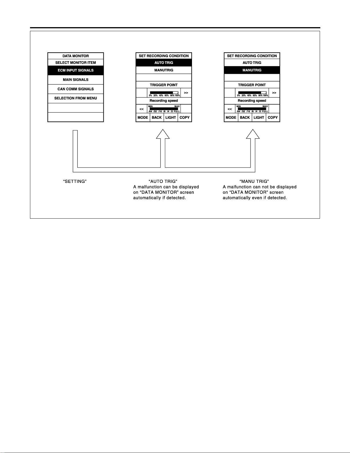
SEC221D
ON BOARD DIAGNOSTIC SYSTEM DESCRIPTION
CONSULT-II (Cont’d)
EC-116
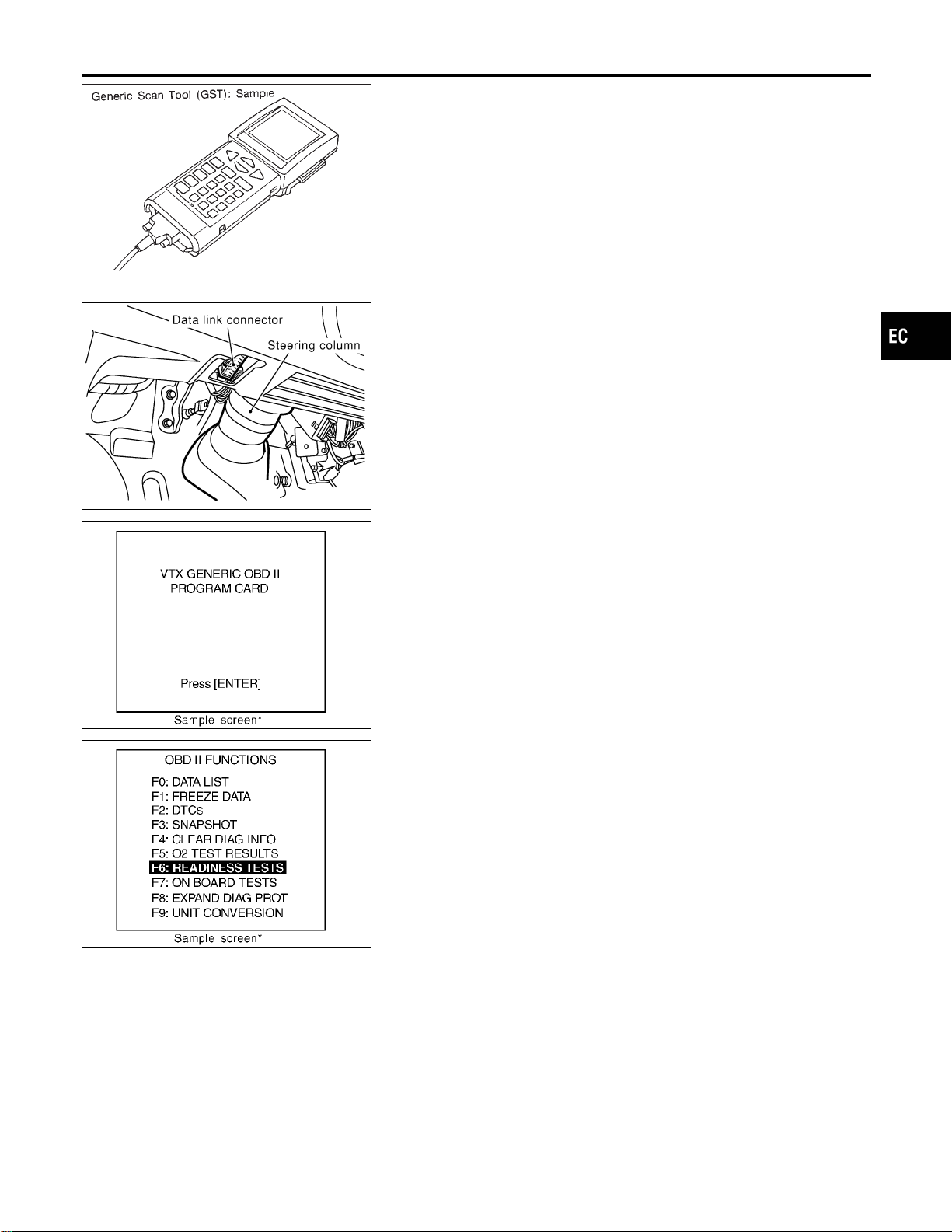
SEF139P
Generic Scan Tool (GST)
=NFEC0035
DESCRIPTION
NFEC0035S01
Generic Scan Tool (OBDII scan tool) complying with SAE J1978
has 8 different functions explained on the next page.
ISO9141 is used as the protocol.
The name “GST” or “Generic Scan Tool” is used in this service
manual.
SEF289X
GST INSPECTION PROCEDURE
NFEC0035S02
1. Turn ignition switch OFF.
2. Connect GST to data link connector, which is located under LH
dash panel near the fuse box cover.
SEF398S
3. Turn ignition switch ON.
4. Enter the program according to instruction on the screen or in
the operation manual.
(*: Regarding GST screens in this section, sample screens are
shown.)
SEF416S
5. Perform each diagnostic mode according to each service pro-
cedure.
For further information, see the GST Operation Manual of the
tool maker.
GI
MA
EM
LC
FE
CL
MT
AT
AX
SU
BR
ST
RS
BT
HA
SC
EL
IDX
ON BOARD DIAGNOSTIC SYSTEM DESCRIPTION
Generic Scan Tool (GST)
EC-117

FUNCTION
NFEC0035S03
Diagnostic test mode Function
MODE 1 READINESS TESTS
This mode gains access to current emission-related data values, including analog
inputs and outputs, digital inputs and outputs, and system status information.
MODE 2 (FREEZE DATA)
This mode gains access to emission-related data value which were stored by ECM
during the freeze frame. [For details, refer to “Freeze Frame Data” (EC-105).]
MODE 3 DTCs
This mode gains access to emission-related power train trouble codes which were
stored by ECM.
MODE 4 CLEAR DIAG INFO
This mode can clear all emission-related diagnostic information. This includes:
I Clear number of diagnostic trouble codes (MODE 1)
I Clear diagnostic trouble codes (MODE 3)
I Clear trouble code for freeze frame data (MODE 1)
I Clear freeze frame data (MODE 2)
I Reset status of system monitoring test (MODE 1)
I Clear on board monitoring test results (MODE 6 and 7)
MODE 6 (ON BOARD TESTS)
This mode accesses the results of on board diagnostic monitoring tests of specific
components/systems that are not continuously monitored.
MODE 7 (ON BOARD TESTS)
This mode enables the off board test drive to obtain test results for emission-related
powertrain components/systems that are continuously monitored during normal driving
conditions.
MODE 8 —
This mode can close EVAP system in ignition switch “ON” position (Engine stopped).
When this mode is performed, the following parts can be opened or closed.
I EVAP canister vent control valve open
I Vacuum cut valve bypass valve closed
In the following conditions, this mode cannot function.
I Low ambient temperature
I Low battery voltage
I Engine running
I Ignition switch “OFF”
I Low fuel temperature
I Too much pressure is applied to EVAP system
MODE 9 (CALIBRATION ID)
This mode enables the off-board test device to request specific vehicle information
such as Vehicle Identification Number (VIN) and Calibration IDs.
ON BOARD DIAGNOSTIC SYSTEM DESCRIPTION
Generic Scan Tool (GST) (Cont’d)
EC-118
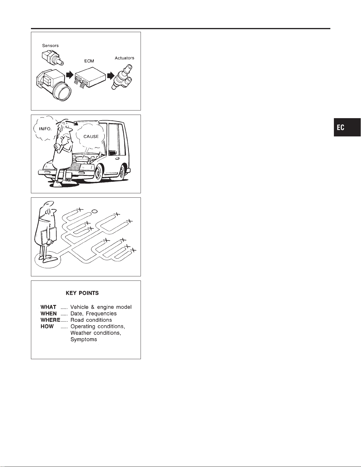
MEF036D
Introduction
NFEC0036
SEF233G
SEF234G
The engine has an ECM to control major systems such as fuel
control, ignition control, idle air control system, etc. The ECM
accepts input signals from sensors and instantly drives actuators.
It is essential that both input and output signals are proper and
stable. At the same time, it is important that there are no problems
such as vacuum leaks, fouled spark plugs, or other problems with
the engine.
It is much more difficult to diagnose a problem that occurs intermit-
tently rather than continuously. Most intermittent problems are
caused by poor electric connections or improper wiring. In this
case, careful checking of suspected circuits may help prevent the
replacement of good parts.
A visual check only may not find the cause of the problems. A road
test with CONSULT-II (or GST) or a circuit tester connected should
be performed. Follow the “Work Flow” on EC-121.
Before undertaking actual checks, take a few minutes to talk with
a customer who approaches with a driveability complaint. The cus-
tomer can supply good information about such problems, espe-
cially intermittent ones. Find out what symptoms are present and
under what conditions they occur.A“Diagnostic Worksheet” like the
example on next page should be used.
Start your diagnosis by looking for “conventional” problems first.
This will help troubleshoot driveability problems on an electronically
controlled engine vehicle.
SEF907L
DIAGNOSTIC WORKSHEET
NFEC0036S01
There are many operating conditions that lead to the malfunction
of engine components. A good grasp of such conditions can make
trouble-shooting faster and more accurate.
In general, each customer feels differently about a problem. It is
important to fully understand the symptoms or conditions for a
customer complaint.
Utilize a diagnostic worksheet like the one on the next page in order
to organize all the information for troubleshooting.
Some conditions may cause the MILto come on steady or blink and
DTC to be detected. Examples:
I Vehicle ran out of fuel, which caused the engine to misfire.
I Fuel filler cap was left off or incorrectly screwed on, allowing
fuel to evaporate into the atmosphere.
GI
MA
EM
LC
FE
CL
MT
AT
AX
SU
BR
ST
RS
BT
HA
SC
EL
IDX
TROUBLE DIAGNOSIS — INTRODUCTION
Introduction
EC-119
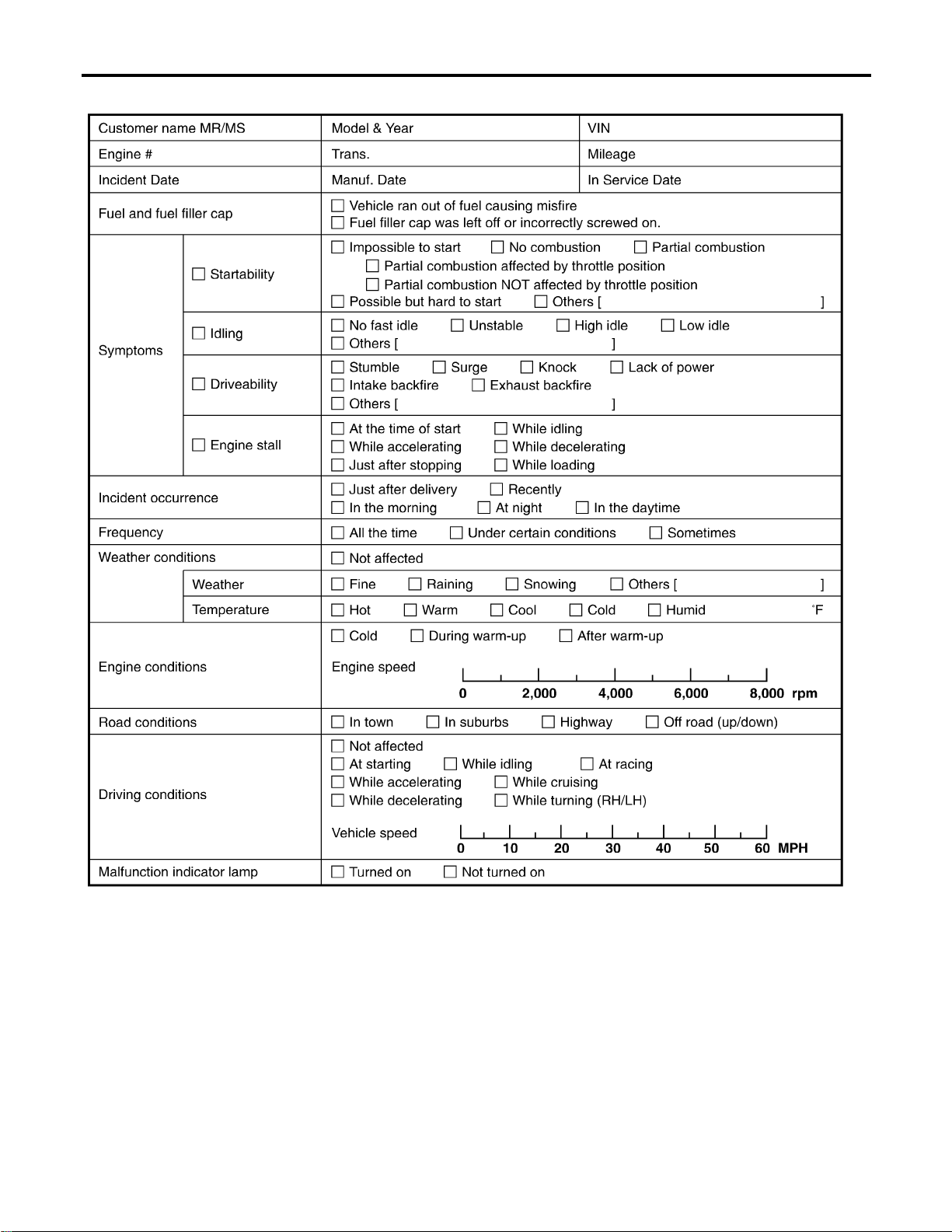
Worksheet Sample
NFEC0036S0101
MTBL0017
TROUBLE DIAGNOSIS — INTRODUCTION
Introduction (Cont’d)
EC-120
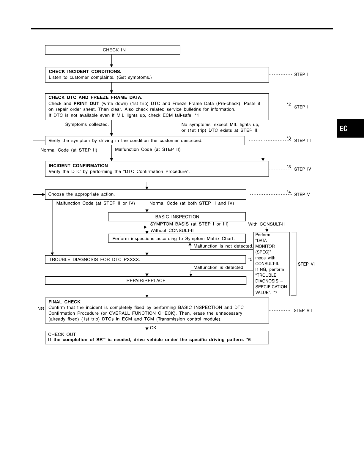
Work Flow
NFEC0037
SEF510ZF
*1 EC-129
*2 If time data of “SELF-DIAG
RESULTS” is other than “0” or
“[1t]”, perform “TROUBLE DIAG-
NOSIS FOR INTERMITTENT
INCIDENT”, EC-156.
*3 If the incident cannot be verified,
perform “TROUBLE DIAGNOSIS
FOR INTERMITTENT INCIDENT”,
EC-156.
*4 If the on board diagnostic system
cannot be performed, check main
power supply and ground circuit.
Refer to “TROUBLE DIAGNOSIS
FOR POWER SUPPLY”, EC-157.
*5 If malfunctioning part cannot be
detected, perform “TROUBLE
DIAGNOSIS FOR INTERMIT-
TENT INCIDENT”, EC-156.
*6 EC-83
*7 EC-152
GI
MA
EM
LC
FE
CL
MT
AT
AX
SU
BR
ST
RS
BT
HA
SC
EL
IDX
TROUBLE DIAGNOSIS — INTRODUCTION
Work Flow
EC-121

DESCRIPTION FOR WORK FLOW
NFEC0037S01
STEP DESCRIPTION
STEP I
Get detailed information about the conditions and the environment when the incident/symptom occurred using
the “DIAGNOSTIC WORK SHEET”, EC-120.
STEP II
Before confirming the concern, check and write down (print out using CONSULT-II or GST) the (1st trip) DTC
and the (1st trip) freeze frame data, then erase the DTC and the data. (Refer to EC-91.) The (1st trip) DTC and
the (1st trip) freeze frame data can be used when duplicating the incident at STEP III & IV.
If the incident cannot be verified, perform “TROUBLE DIAGNOSIS FOR INTERMITTENT INCIDENT”, EC-156.
Study the relationship between the cause, specified by (1st trip) DTC, and the symptom described by the cus-
tomer. (The “Symptom Matrix Chart” will be useful. See EC-131.)
Also check related service bulletins for information.
STEP III
Try to confirm the symptom and under what conditions the incident occurs.
The “DIAGNOSTIC WORK SHEET” and the freeze frame data are useful to verify the incident. Connect CON-
SULT-II to the vehicle in DATA MONITOR (AUTO TRIG) mode and check real time diagnosis results.
If the incident cannot be verified, perform “TROUBLE DIAGNOSIS FOR INTERMITTENT INCIDENT”, EC-156.
If the malfunction code is detected, skip STEP IV and perform STEP V.
STEP IV
Try to detect the (1st trip) DTC by driving in (or performing) the “DTC Confirmation Procedure”. Check and read
the (1st trip) DTC and (1st trip) freeze frame data by using CONSULT-II or GST.
During the (1st trip) DTC verification, be sure to connect CONSULT-II to the vehicle in DATA MONITOR (AUTO
TRIG) mode and check real time diagnosis results.
If the incident cannot be verified, perform “TROUBLE DIAGNOSIS FOR INTERMITTENT INCIDENT”, EC-156.
In case the “DTC Confirmation Procedure” is not available, perform the “Overall Function Check” instead. The
(1st trip) DTC cannot be displayed by this check, however, this simplified “check” is an effective alternative.
The “NG” result of the “Overall Function Check” is the same as the (1st trip) DTC detection.
STEP V
Take the appropriate action based on the results of STEP I through IV.
If the malfunction code is indicated, proceed to TROUBLE DIAGNOSIS FOR DTC PXXXX.
If the normal code is indicated, proceed to the BASIC INSPECTION. (Refer to EC-123.) If CONSULT-II is
available, perform “DATA MONITOR (SPEC)” mode with CONSULT-II and proceed to the “TROUBLE DIAGNO-
SIS — SPECIFICATION VALUE”, EC-152. (If malfunction is detected, proceed to “REPAIR REPLACE”.) Then
perform inspections according to the Symptom Matrix Chart. (Refer to EC-131.)
STEP VI
Identify where to begin diagnosis based on the relationship study between symptom and possible causes.
Inspect the system for mechanical binding, loose connectors or wiring damage using (tracing) “Harness Layouts”.
Gently shake the related connectors, components or wiring harness with CONSULT-II set in “DATA MONITOR
(AUTO TRIG)” mode.
Check the voltage of the related ECM terminals or monitor the output data from the related sensors with CON-
SULT-II. Refer to EC-135, 141.
The “Diagnostic Procedure” in EC section contains a description based on open circuit inspection. A short circuit
inspection is also required for the circuit check in the Diagnostic Procedure. For details, refer to GI-22, “Circuit
Inspection”.
Repair or replace the malfunction parts.
If malfunctioning part cannot be detected, perform “TROUBLE DIAGNOSIS FOR INTERMITTENT INCIDENT”,
EC-156.
STEP VII
Once you have repaired the circuit or replaced a component, you need to run the engine in the same conditions
and circumstances which resulted in the customer’s initial complaint.
Perform the “DTC Confirmation Procedure” and confirm the normal code [DTC No. P0000] is detected. If the
incident is still detected in the final check, perform STEP VI by using a different method from the previous one.
Before returning the vehicle to the customer, be sure to erase the unnecessary (already fixed) (1st trip) DTC in
ECM and TCM (Transmission control module). (Refer to EC-91.)
TROUBLE DIAGNOSIS — INTRODUCTION
Work Flow (Cont’d)
EC-122
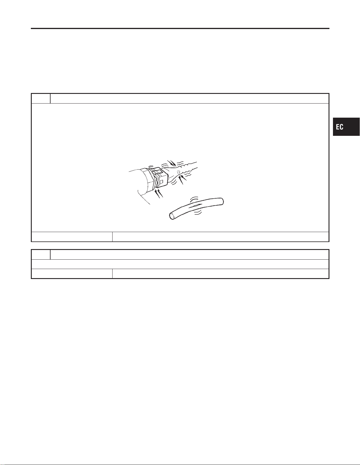
Basic Inspection
NFEC0038
Precaution:
Perform Basic Inspection without electrical or mechanical
loads applied;
I Headlamp switch is OFF,
I Air conditioner switch is OFF,
I Rear window defogger switch is OFF,
I Steering wheel is in the straight-ahead position, etc.
1 INSPECTION START
1. Check service records for any recent repairs that may indicate a related problem, or a current need for scheduled
maintenance.
2. Open engine hood and check the following:
I Harness connectors for improper connections
I Vacuum hoses for splits, kinks and improper connections
I Wiring for improper connections, pinches and cuts
I Air cleaner clogging
I Hoses and ducts for leaks
SEF983U
© GO TO 2.
2 REPAIR OR REPLACE
Repair or replace components as necessary according to corresponding “Diagnostic Procedure”.
© GO TO 3.
GI
MA
EM
LC
FE
CL
MT
AT
AX
SU
BR
ST
RS
BT
HA
SC
EL
IDX
TROUBLE DIAGNOSIS — BASIC INSPECTION
Basic Inspection
EC-123
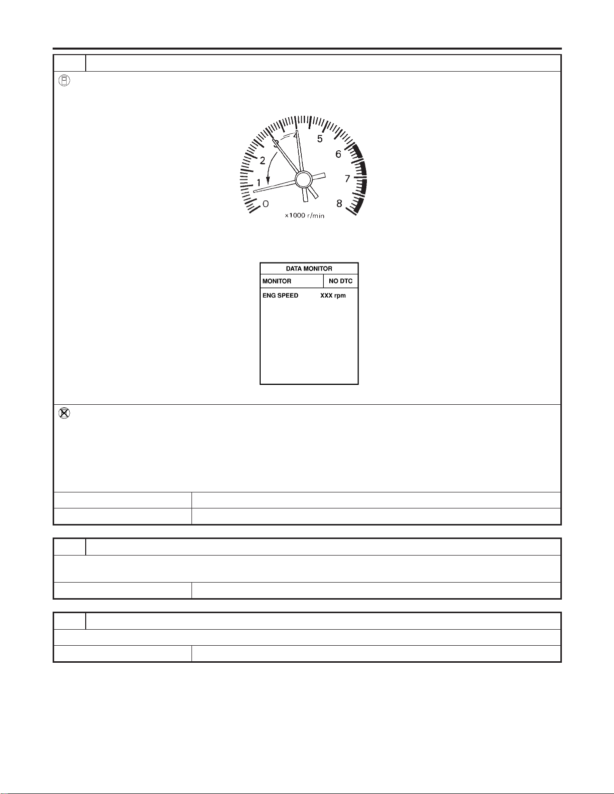
3 CHECK TARGET IDLE SPEED
With CONSULT-II
1. Run engine at about 2,000 rpm for about 2 minutes under no-load.
2. Rev engine (2,000 to 3,000 rpm) two or three times under no-load, then run engine at idle speed for about 1 minute.
SEF978U
3. Read idle speed in “DATA MONITOR” mode with CONSULT-II.
MT: 625±50 rpm
AT: 675±50 rpm (in “P” or “N” position)
SEF058Y
Without CONSULT-II
1. Run engine at about 2,000 rpm for about 2 minutes under no-load.
2. Rev engine (2,000 to 3,000 rpm) two or three times under no-load, then run engine at idle speed for about 1 minute.
3. Check idle speed.
MT: 625±50 rpm
AT: 675±50 rpm (in “P” or “N” position)
OK or NG
OK © GO TO 9.
NG © GO TO 4.
4 PERFORM ACCELERATOR PEDAL RELEASED POSITION LEARNING
1. Stop engine.
2. Perform “Accelerator Pedal Released Position Learning”, EC-71.
© GO TO 5.
5 PERFORM THROTTLE VALVE CLOSED POSITION LEARNING
Perform “Throttle Valve Closed Position Learning”, EC-71.
© GO TO 6.
TROUBLE DIAGNOSIS — BASIC INSPECTION
Basic Inspection (Cont’d)
EC-124
6 PERFORM IDLE AIR VOLUME LEARNING
Refer to “Idle Air Volume Learning”, EC-71.
Which is the result CMPLT or INCMP?
CMPLT © GO TO 7.
INCMP © 1. Follow the construction of “Idle Air Volume Learning”.
2. GO TO 4.
7 CHECK TARGET IDLE SPEED AGAIN
With CONSULT-II
1. Start engine and warm it up to normal operating temperature.
2. Read idle speed in “DATA MONITOR” mode with CONSULT-II.
MT: 625±50 rpm
AT: 675±50 rpm (in “P” or “N” position)
Without CONSULT-II
1. Start engine and warm it up to normal operating temperature.
2. Check idle speed.
MT: 625±50 rpm
AT: 675±50 rpm (in “P” or “N” position)
OK or NG
OK © GO TO 10.
NG © GO TO 8.
8 DETECT MALFUNCTIONING PART
Check the following.
I Check camshaft position sensor (PHASE) and circuit. Refer to EC-337.
I Check crankshaft position sensor (POS) and circuit. Refer to EC-330.
OK or NG
OK © GO TO 9.
NG © 1. Repair or replace.
2. GO TO 4.
9 CHECK ECM FUNCTION
1. Substitute another known-good ECM to check ECM function. (ECM may be the cause of a malfunction, but this is the
rarely the case.)
2. Perform initialization of NVIS (NATS) system and registration of NVIS (NATS) ignition key IDs. Refer to “NVIS (NISSAN
VEHICLE IMMOBILIZER SYSTEM — NATS)”, EC-92.
© GO TO 4.
10 CHECK IGNITION TIMING
1. Run engine at idle.
2. Check ignition timing with a timing light.
MT: 15°±5° BTDC
AT: 15°±5° BTDC (in “P” or “N” position)
OK or NG
OK © INSPECTION END
NG © GO TO 11.
GI
MA
EM
LC
FE
CL
MT
AT
AX
SU
BR
ST
RS
BT
HA
SC
EL
IDX
TROUBLE DIAGNOSIS — BASIC INSPECTION
Basic Inspection (Cont’d)
EC-125
11 PERFORM ACCELERATOR PEDAL RELEASED POSITION LEARNING
1. Stop engine.
2. Perform “Accelerator Pedal Released Position Learning”, EC-71.
© GO TO 12.
12 PERFORM THROTTLE VALVE CLOSED POSITION LEARNING
Perform “Throttle Valve Closed Position Learning”, EC-71.
© GO TO 13.
13 PERFORM IDLE AIR VOLUME LEARNING
Refer to “Idle Air Volume Learning”, EC-71.
Which is the result CMPLT or INCMP?
CMPLT © GO TO 14.
INCMP © 1. Follow the construction of “Idle Air Volume Learning”.
2. GO TO 4.
14 CHECK TARGET IDLE SPEED AGAIN
With CONSULT-II
1. Start engine and warm it up to normal operating temperature.
2. Read idle speed in “DATA MONITOR” mode with CONSULT-II.
MT: 625±50 rpm
AT: 675±50 rpm (in “P” or “N” position)
Without CONSULT-II
1. Start engine and warm it up to normal operating temperature.
2. Check idle speed.
MT: 625±50 rpm
AT: 675±50 rpm (in “P” or “N” position)
OK or NG
OK © GO TO 15.
NG © GO TO 17.
15 CHECK IGNITION TIMING AGAIN
1. Run engine at idle.
2. Check ignition timing with a timing light.
MT: 15°±5° BTDC
AT: 15°±5° BTDC (in “P” or “N” position)
OK or NG
OK © INSPECTION END
NG © GO TO 16.
16 CHECK TIMING CHAIN INSTALLATION
Check timing chain installation. Refer to EM-21, “TIMING CHAIN”.
OK or NG
OK © GO TO 17.
NG © 1. Repair the timing chain installation.
2. GO TO 4.
TROUBLE DIAGNOSIS — BASIC INSPECTION
Basic Inspection (Cont’d)
EC-126
17 DETECT MALFUNCTIONING PART
Check the following.
I Check camshaft position sensor (PHASE) and circuit. Refer to EC-337.
I Check crankshaft position sensor (POS) and circuit. Refer to EC-330.
OK or NG
OK © GO TO 18.
NG © 1. Repair or replace.
2. GO TO 4.
18 CHECK ECM FUNCTION
1. Substitute another known-good ECM to check ECM function. (ECM may be the cause of a malfunction, but this is the
rarely the case.)
2. Perform initialization of NVIS (NATS) system and registration of NVIS (NATS) ignition key IDs. Refer to “NVIS (NISSAN
VEHICLE IMMOBILIZER SYSTEM — NATS)”, EC-92.
© GO TO 4.
GI
MA
EM
LC
FE
CL
MT
AT
AX
SU
BR
ST
RS
BT
HA
SC
EL
IDX
TROUBLE DIAGNOSIS — BASIC INSPECTION
Basic Inspection (Cont’d)
EC-127

DTC Inspection Priority Chart
NFEC0039
If some DTCs are displayed at the same time, perform inspections one by one based on the following prior-
ity chart.
Priority Detected items (DTC)
1 I U1000, U1001 CAN communication line
I P0101, P0102, P0103, P1102 MAF sensor
I P0112, P0113, P0127 IAT sensor
I P0117, P0118, P0125 ECT sensor
I P0121, P0226, P0227, P0228, P1227, P1228 Accelerator pedal position sensor
I P0128 Thermostat function
I P0122, P0123, P0221, P0222, P0223, P1223, P1224, P1225, P1226, P1229 Throttle position sensor
I P0181, P0182, P0183 FTT sensor
I P0327, P0328 KS
I P0335 CKP sensor (POS)
I P0340, P0345 CMP sensor (PHASE)
I P0460, P0461, P0462, P0463, P1464 Fuel level sensor
I P0500 VSS
I P0605 ECM
I P0705 Park/Neutral position switch
I P1706 PNP switch
2 I P0031, P0032, P0051, P0052 HO2S1 heater
I P0037, P0038, P0057, P0058 HO2S2 heater
I P0107, P0108 Absolute pressure sensor
I P0132-P0134, P1143, P1144 and P0152-P0154, P1163, P1164 HO2S1
I P0138, P0139, P1146, P1147 and P0158, P0159, P1166, P1167 HO2S2
I P0441 EVAP control system purge flow monitoring
I P0444, P0445, P1444 EVAP canister purge volume control solenoid valve
I P0447, P1446, P1448 EVAP canister vent control valve
I P0452, P0453 EVAP control system pressure sensor
I P0550 Power steering pressure sensor
I P0650 MIL
I P0710, P0720, P0725, P0740, P0745, P0750, P1705, P1760 A/T related sensors, solenoid valves and
switches
I P1065 ECM power supply
I P1122 Electric throttle control function
I P1217 Engine overtemperature (OVERHEAT)
I P1490, P1491 Vacuum cut valve bypass valve
I P1800 VIAS control solenoid valve
I P1805 Brake switch
3 I P0011, P0021 Intake valve timing control
I P0171, P0172 and P0174, P0175 Fuel injection system function
I P0300-P0306 Misfire
I P0420, P0430 Three way catalyst function
I P0442, P0456/P1456 EVAP control system (SMALL LEAK, VERY SMALL LEAK)
I P0455 EVAP control system (GROSS LEAK)
I P0506, P0507 ISC system
I P0731-P0734, P0744 A/T function
I P1121 Electric throttle control actuator
I P1124, P1126 Throttle control motor relay
I P1128 Throttle control motor
I P1148, P1168 Closed loop control
I P1211 ABS/TCS control unit
I P1212 ABS/TCS communication line
I P1564 ASCD steering switch
I P1572 ASCD brake switch
I P1574 ASCD Vehicle speed sensor
TROUBLE DIAGNOSIS — GENERAL DESCRIPTION
DTC Inspection Priority Chart
EC-128
Fail-safe Chart
=NFEC1425
The ECM enters fail-safe mode, if any of the following malfunctions is detected due to the open or short cir-
cuit. When the ECM enters the fail-safe mode, the MIL illuminates.
DTC No. Detected items Engine operating condition in fail-safe mode
P0102, P0103,
P1102
Mass air flow sensor circuit Engine speed will not rise more than 2,400 rpm due to the fuel cut.
P0117, P0118 Engine coolant temperature
sensor circuit
Engine coolant temperature will be determined by ECM based on the time after
turning ignition switch “ON” or “START”.
CONSULT-II displays the engine coolant temperature decided by ECM.
Condition
Engine coolant temperature decided
(CONSULT-II display)
Just as ignition switch is turned
ON or Start
40°C (104°F)
More than approx. 4 minutes
after ignition ON or Start
80°C (176°F)
Except as shown above
40 - 80°C (104 - 176°F)
(Depends on the time)
When the fail-safe system for engine coolant temperature sensor is activated, the
cooling fan operates while engine is running.
P0221, P0222,
P0223, P1223,
P1224
Throttle position sensor The ECM controls the electric throttle control actuator in regulating the throttle
opening in order for the idle position to be within +10 degrees.
The ECM regulates an opening speed of approx. 5 seconds to an opening of 10
degrees. So, the acceleration will be poor.
P0226, P0227,
P0228, P1227,
P1228
Accelerator pedal position
sensor
The ECM controls the electric throttle control actuator in regulating the throttle
opening in order for the idle position to be within +10 degrees.
The ECM regulates an opening speed of approx. 5 seconds to an opening of 10
degrees. So, the acceleration will be poor.
P1121 Electric throttle control
actuator
(ECM detect the throttle
valve is stuck open.)
While the vehicle is driving, it slows down gradually by fuel cut. After the vehicle
stops, the engine stalls.
The engine can restart in “N” or “P” position, and engine speed will not exceed
1,000 rpm or more.
P1122 Electric throttle control func-
tion
ECM stops the electric throttle control actuator control, throttle valve is maintained
at a fixed opening (approx. 5 degrees) by the return spring.
P1126 Throttle control relay ECM stops the electric throttle control actuator control, throttle valve is maintained
at a fixed opening (approx. 5 degrees) by the return spring.
P1129 Sensor power supply ECM stops the electric throttle control actuator control, throttle valve is maintained
at a fixed opening (approx. 5 degrees) by the return spring.
GI
MA
EM
LC
FE
CL
MT
AT
AX
SU
BR
ST
RS
BT
HA
SC
EL
IDX
TROUBLE DIAGNOSIS — GENERAL DESCRIPTION
Fail-safe Chart
EC-129
DTC No. Detected items Engine operating condition in fail-safe mode
Unable to
access ECM
ECM ECM fail-safe activating condition
The computing function of the ECM was judged to be malfunctioning.
When the fail-safe system activates (i.e., if the ECM detects a malfunction condi-
tion in the CPU of ECM), the MIL on the instrument panel lights to warn the driver.
However it is not possible to access ECM and DTC cannot be confirmed.
Engine control with fail-safe
When ECM fail-safe is operating, fuel injection, ignition timing, fuel pump operation
and cooling fan operation are controlled under certain limitations.
ECM fail-safe operation
Engine speed
Engine speed will not rise more than 3,000
rpm
Fuel injection Simultaneous multiport fuel injection system
Ignition timing Ignition timing is fixed at the preset valve
Cooling fans
Cooling fan relay is “ON” (High speed condition)
when engine is running, and “OFF” when engine
stalls.
Fuel pump
Fuel pump relay is “ON” when engine is running
and “OFF” when engine stalls
Replace ECM, if ECM fail-safe condition is confirmed.
TROUBLE DIAGNOSIS — GENERAL DESCRIPTION
Fail-safe Chart (Cont’d)
EC-130
Symptom Matrix Chart
NFEC0041
SYSTEM — BASIC ENGINE CONTROL SYSTEM
NFEC0041S01
SYMPTOM
Reference
page
HARD/NO START/RESTART (EXCP. HA)
ENGINE STALL
HESITATION/SURGING/FLAT SPOT
SPARK KNOCK/DETONATION
LACK OF POWER/POOR ACCELERATION
HIGH IDLE/LOW IDLE
ROUGH IDLE/HUNTING
IDLING VIBRATION
SLOW/NO RETURN TO IDLE
OVERHEATS/WATER TEMPERATURE HIGH
EXCESSIVE FUEL CONSUMPTION
EXCESSIVE OIL CONSUMPTION
BATTERY DEAD (UNDER CHARGE)
Warranty symptom code AA AB AC AD AE AF AG AH AJ AK AL AM HA
Fuel Fuel pump circuit 11232 2 2 3 2EC-713
Fuel pressure regulator system 3344444 4 4 4 EC-56
Injector circuit 11232 2 2 2 EC-703
Evaporative emission system
33
44444 4 4 4
EC-36
Air Positive crankcase ventilation sys-
tem
1 EC-51
Incorrect idle speed adjustment 1 1 1 1 1 EC-123
Electric throttle control actuator
1123322 2 2 2 2
EC-471, 473,
481, 487
Ignition Incorrect ignition timing adjustment 33111 1 1 1 EC-123
Ignition circuit 11222 2 2 2 EC-692
Main power supply and ground circuit
22333 3 3
2
3
EC-157
Air conditioner circuit 3 3 2 HA section
ABS/TCS control unit 4 EC-528, 530
1 - 6: The numbers refer to the order of inspection.
(continued on next page)
GI
MA
EM
LC
FE
CL
MT
AT
AX
SU
BR
ST
RS
BT
HA
SC
EL
IDX
TROUBLE DIAGNOSIS — GENERAL DESCRIPTION
Symptom Matrix Chart
EC-131
SYMPTOM
Reference
page
HARD/NO START/RESTART (EXCP. HA)
ENGINE STALL
HESITATION/SURGING/FLAT SPOT
SPARK KNOCK/DETONATION
LACK OF POWER/POOR ACCELERATION
HIGH IDLE/LOW IDLE
ROUGH IDLE/HUNTING
IDLING VIBRATION
SLOW/NO RETURN TO IDLE
OVERHEATS/WATER TEMPERATURE HIGH
EXCESSIVE FUEL CONSUMPTION
EXCESSIVE OIL CONSUMPTION
BATTERY DEAD (UNDER CHARGE)
Warranty symptom code AA AB AC AD AE AF AG AH AJ AK AL AM HA
Engine
control
Crankshaft position sensor (POS)
circuit
2 2 EC-330
Camshaft position sensor
(PHASE) circuit
32
EC-337
Mass air flow sensor circuit
1
12
2
222 2
EC-188, 195,
465
Heated oxygen sensor 1 circuit
3
EC-220, 228,
240, 492, 499
Engine coolant temperature sen-
sor circuit
1 3 3 EC-207, 213
Throttle position sensor circuit
22
EC-290, 297,
550, 557, 559
Accelerator pedal position sensor
circuit
3 11111
EC-304, 311,
561
Vehicle speed sensor circuit 2 3 3
3
EC-442
Knock sensor circuit 2 EC-325
ECM 2233333 3 33 EC-455, 129
Start signal circuit 2 EC-709
Park/Neutral position switch circuit 3 3
33
3 EC-667
Power steering pressure sensor
circuit
2 EC-450
Electrical load signal circuit EC-744
1 - 6: The numbers refer to the order of inspection.
(continued on next page)
TROUBLE DIAGNOSIS — GENERAL DESCRIPTION
Symptom Matrix Chart (Cont’d)
EC-132
SYSTEM — ENGINE MECHANICAL & OTHER
NFEC0041S02
SYMPTOM
Reference
section
HARD/NO START/RESTART (EXCP. HA)
ENGINE STALL
HESITATION/SURGING/FLAT SPOT
SPARK KNOCK/DETONATION
LACK OF POWER/POOR ACCELERATION
HIGH IDLE/LOW IDLE
ROUGH IDLE/HUNTING
IDLING VIBRATION
SLOW/NO RETURN TO IDLE
OVERHEATS/WATER TEMPERATURE HIGH
EXCESSIVE FUEL CONSUMPTION
EXCESSIVE OIL CONSUMPTION
BATTERY DEAD (UNDER CHARGE)
Warranty symptom code AA AB AC AD AE AF AG AH AJ AK AL AM HA
Fuel Fuel tank
5
5
FE section
Fuel piping 5 5 5 5 5 5
—
Vapor lock
Valve deposit
5 555 5 5 5
Poor fuel (Heavy weight gasoline,
Low octane)
Air Air duct
55555 5
Air cleaner
Air leakage from air duct
(Mass air flow sensor — throttle
body)
555 5
Air leakage from intake manifold/
Collector/Gasket
—
Cranking Battery
111111 11
EL sectionAlternator circuit
Starter circuit 3
Flywheel/Drive plate 6 EM section
PNP switch 4 AT section
1 - 6: The numbers refer to the order of inspection.
(continued on next page)
GI
MA
EM
LC
FE
CL
MT
AT
AX
SU
BR
ST
RS
BT
HA
SC
EL
IDX
TROUBLE DIAGNOSIS — GENERAL DESCRIPTION
Symptom Matrix Chart (Cont’d)
EC-133
SYMPTOM
Reference
section
HARD/NO START/RESTART (EXCP. HA)
ENGINE STALL
HESITATION/SURGING/FLAT SPOT
SPARK KNOCK/DETONATION
LACK OF POWER/POOR ACCELERATION
HIGH IDLE/LOW IDLE
ROUGH IDLE/HUNTING
IDLING VIBRATION
SLOW/NO RETURN TO IDLE
OVERHEATS/WATER TEMPERATURE HIGH
EXCESSIVE FUEL CONSUMPTION
EXCESSIVE OIL CONSUMPTION
BATTERY DEAD (UNDER CHARGE)
Warranty symptom code AA AB AC AD AE AF AG AH AJ AK AL AM HA
Engine Cylinder head
55555 5 5 5
EM section
Cylinder head gasket 4 3
Cylinder block
66666 6 6 6
4Piston
Piston ring
Connecting rod
Bearing
Crankshaft
Valve
mechanism
Timing chain
55555 5 5 5
Camshaft
Intake valve timing control
Intake valve
3
Exhaust valve
Exhaust Exhaust manifold/Tube/Muffler/
Gasket
5555555 5 FEsection
Three way catalyst
Lubrication Oil pan/Oil strainer/Oil pump/Oil
filter/Oil gallery
55555 5 5 5
MA, EM, LC
section
Oil level (Low)/Filthy oil LC section
Cooling Radiator/Hose/Radiator filler cap
55555 5 5 45
Thermostat 5
Water pump
Water gallery
Coolant level (low)/Contaminated
coolant
MA section
1 - 6: The numbers refer to the order of inspection.
TROUBLE DIAGNOSIS — GENERAL DESCRIPTION
Symptom Matrix Chart (Cont’d)
EC-134
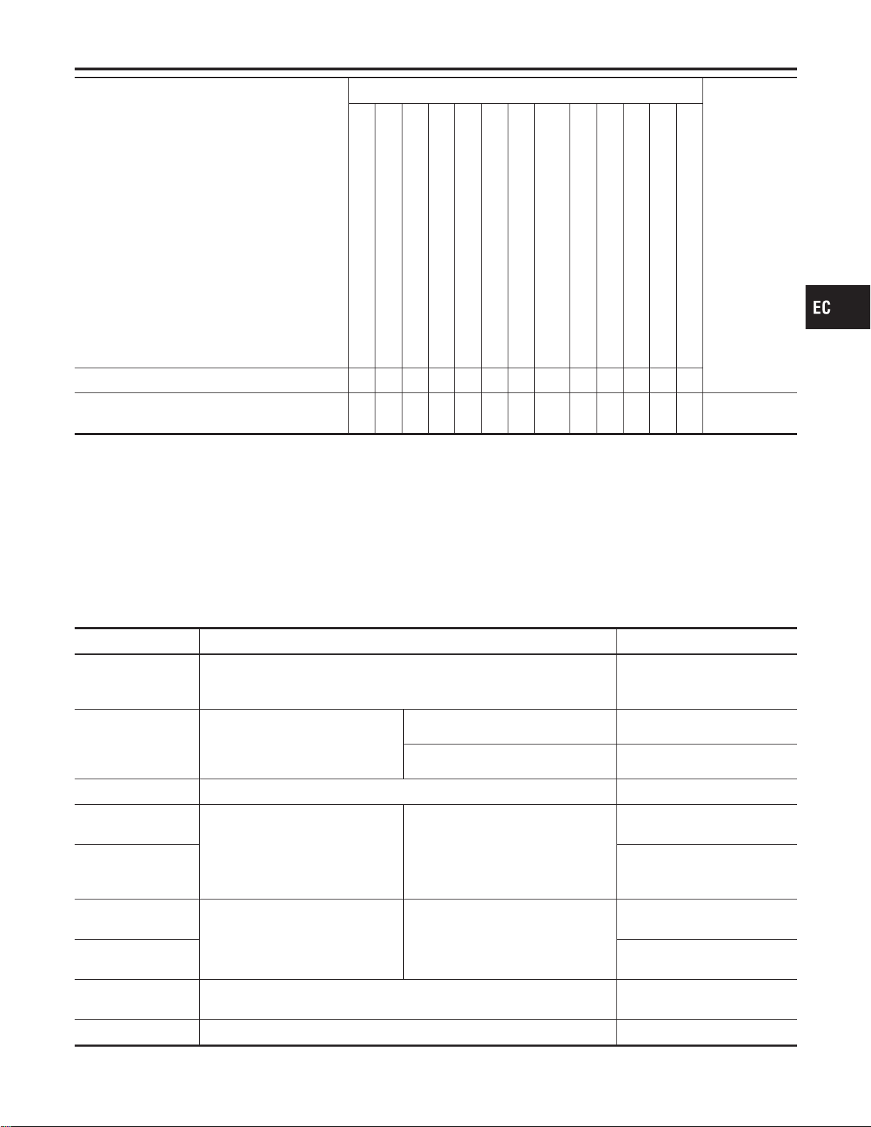
SYMPTOM
Reference
section
HARD/NO START/RESTART (EXCP. HA)
ENGINE STALL
HESITATION/SURGING/FLAT SPOT
SPARK KNOCK/DETONATION
LACK OF POWER/POOR ACCELERATION
HIGH IDLE/LOW IDLE
ROUGH IDLE/HUNTING
IDLING VIBRATION
SLOW/NO RETURN TO IDLE
OVERHEATS/WATER TEMPERATURE HIGH
EXCESSIVE FUEL CONSUMPTION
EXCESSIVE OIL CONSUMPTION
BATTERY DEAD (UNDER CHARGE)
Warranty symptom code AA AB AC AD AE AF AG AH AJ AK AL AM HA
NVIS (NISSAN Vehicle Immobilizer System —
NATS)
11
EC-92 or EL
section
1 - 6: The numbers refer to the order of inspection.
CONSULT-II Reference Value in Data Monitor
Mode
NFEC1426
Remarks:
I Specification data are reference values.
I Specification data are output/input values which are detected or supplied by the ECM at the connector.
* Specification data may not be directly related to their components signals/values/operations.
i.e. Adjust ignition timing with a timing light before monitoring IGN TIMING, because the monitor may show the specification data in
spite of the ignition timing not being adjusted to the specification data. This IGN TIMING monitors the data calculated by the ECM
according to the signals input from the camshaft position sensor and other ignition timing related sensors.
MONITOR ITEM CONDITION SPECIFICATION
ENG SPEED
I Tachometer: Connect
I Run engine and compare tachometer indication with the CONSULT-II
value.
Almost the same speed as the
CONSULT-II value.
MAS A/F SE-B1
I Engine: After warming up
I Air conditioner switch: “OFF”
I Shift lever: “N”
I No-load
Idle 1.1 - 1.5V
2,500 rpm 1.7 - 2.4V
COOLAN TEMP/S I Engine: After warming up More than 70°C (158°F)
HO2S1 (B1)
HO2S1 (B2)
I Engine: After warming up
Maintaining engine speed at 2,000
rpm
0 - 0.3V +, Approx. 0.6 -
1.0V
HO2S1 MNTR (B1)
HO2S1 MNTR (B2)
LEAN +, RICH
Changes more than 5 times
during 10 seconds.
HO2S2 (B1)
HO2S2 (B2)
I Engine: After warming up
Maintaining engine speed at 2,000
rpm
0 - 0.3V +, Approx. 0.6 -
1.0V
HO2S2 MNTR (B1)
HO2S2 MNTR (B2)
LEAN +, RICH
VHCL SPEED SE
I Turn drive wheels and compare speedometer indication with the CON-
SULT-II value
Almost the same speed as the
CONSULT-II value
BATTERY VOLT I Ignition switch: ON (Engine stopped) 11 - 14V
GI
MA
EM
LC
FE
CL
MT
AT
AX
SU
BR
ST
RS
BT
HA
SC
EL
IDX
TROUBLE DIAGNOSIS — GENERAL DESCRIPTION
Symptom Matrix Chart (Cont’d)
EC-135

MONITOR ITEM CONDITION SPECIFICATION
ACCEL SEN 1
I Ignition switch: ON
(Engine stopped)
I Shift lever: “D”
Accelerator pedal: Fully released
0.41 - 0.71V
Accelerator pedal: Fully depressed More than 3.7V
ACCEL SEN 2
I Ignition switch: ON
(Engine stopped)
I Shift lever: “D”
Accelerator pedal: Fully released
0.15 - 0.71V
Accelerator pedal: Fully depressed More than 3.5V
THRTL SEN 1
THRTL SEN 2
I Ignition switch: ON
(Engine stopped)
I Shift lever: “D”
Accelerator pedal: Fully released
More than 0.36V
Accelerator pedal: Fully depressed Less than 4.75V
START SIGNAL I Ignition switch: ON , START , ON OFF , ON , OFF
CLSD THL POS
I Ignition switch: ON
I Shift lever: “D”
Accelerator pedal: Fully released ON
Accelerator pedal: Slightly depressed OFF
AIR COND SIG
I Engine: After warming up, idle
the engine
Air conditioner switch: “OFF” OFF
Air conditioner switch: “ON”
(Compressor operates.)
ON
P/N POSI SW I Ignition switch: ON
Shift lever: “P” or “N” ON
Except above OFF
PW/ST SIGNAL
I Engine: After warming up, idle
the engine
Steering wheel in neutral position
(forward direction)
OFF
The steering wheel is turned ON
IGNITION SW I Ignition switch: ON , OFF , ON ON , OFF , ON
INJ PULSE-B1
INJ PULSE-B2
I Engine: After warming up
I Air conditioner switch: “OFF”
I Shift lever: “N”
I No-load
Idle 2.0 - 3.0 msec
2,000 rpm 1.9 - 2.9 msec
B/FUEL SCHDL
I Engine: After warming up
I Air conditioner switch: “OFF”
I Shift lever: “N”
I No-load
Idle 2.3 - 2.9 msec
2,000 rpm 2.3 - 2.9 msec
IGN TIMING
I Engine: After warming up
I Air conditioner switch: “OFF”
I Shift lever: “N”
I No-load
Idle 13 - 18° BTDC
2,000 rpm 25 - 45° BTDC
LOAD SIGNAL I Ignition switch: ON
Rear window defogger switch is ON
and/or lighting switch is in 2nd.
ON
Rear window defogger switch is OFF
and lighting switch is OFF.
OFF
PURG VOL C/V
I Engine: After warming up
I Air conditioner switch: “OFF”
I Shift lever: “N”
I No-load
Idle 0 %
2,000 rpm —
A/F ALPHA-B1
A/F ALPHA-B2
I Engine: After warming up
Maintaining engine speed at 2,000
rpm
54 - 155%
EVAP SYS PRES I Ignition switch: ON Approx. 3.4V
AIR COND RLY I Air conditioner switch: OFF , ON OFF , ON
FUEL PUMP RLY
I Ignition switch is turned to ON (Operates for 1 seconds)
I Engine running or cranking
ON
Except as shown above OFF
TROUBLE DIAGNOSIS — GENERAL DESCRIPTION
CONSULT-II Reference Value in Data Monitor Mode (Cont’d)
EC-136
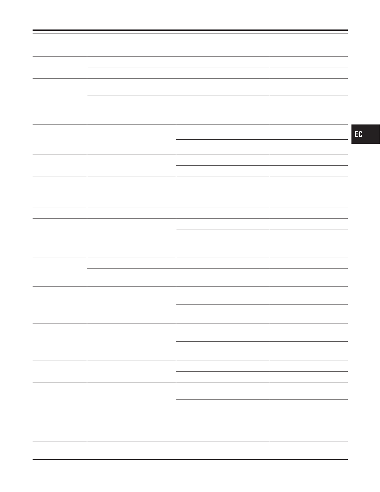
MONITOR ITEM CONDITION SPECIFICATION
VENT CONT/V I Ignition switch: ON OFF
HO2S1 HTR (B1)
HO2S1 HTR (B2)
I Engine speed: Below 3,600 rpm ON
I Engine speed: Above 3,600 rpm OFF
HO2S2 HTR (B1)
HO2S2 HTR (B2)
I Ignition switch: ON (Engine stopped)
I Engine speed: Above 3,600 rpm
OFF
I Engine speed: Below 3,600 rpm [After driving for 2 minutes at a speed
of 70 km/h (43 MPH) or more]
ON
VC/V BYPASS/V Ignition switch: ON OFF
CAL/LD VALUE
I Engine: After warming up
I Air conditioner switch: “OFF”
I Shift lever: “N”
I No-load
Idle 10 - 35%
2,500 rpm 10 - 35%
BRAKE SW I Ignition switch: ON
Brake pedal: Fully released OFF
Brake pedal: Slightly depressed ON
MASS AIRFLOW
I Engine: After warming up
I Air conditioner switch: “OFF”
I Shift lever: “N”
I No-load
Idle 2.0 - 6.0 g·m/s
2,500 rpm 7.0 - 20.0 g·m/s
ABSOL PRES/SE I Ignition switch: ON Approx. 4.4V
VIAS S/V I Engine: After warming up
1,800 - 3,600 rpm ON
Except above conditions OFF
TRVL AFTER MIL Ignition switch: ON
Vehicle has traveled after MIL has
turned ON.
0 - 65,535 km
(0 - 40,723 mile)
AC PRESS SEN
I Ignition switch: ON (Engine stopped) Approx. 0V
I Engine: Idle
I Air conditioner switch: OFF
1.0 - 4.0V
INT/V TIM (B1)
INT/V TIM (B2)
I Engine: After warming up
I Shift lever “N”
I Quickly depressed accelerator
pedal
I No-load
Idle
−5-5°CA
2,000 rpm
Approximately 0 - 30° CA
INT/V SOL (B1)
INT/V SOL (B2)
I Engine: After warming up
I Shift lever “N”
I Quickly depressed accelerator
pedal
I No-load
Idle
0-2%
2,000 rpm Approximately 25 - 50%
ENGINE MOUNT I Engine: Running
Idle “IDLE”
2,000 rpm “TRVL”
COOLING FAN
I After warming up engine, idle the
engine.
I After conditioner switch: “OFF”
Engine coolant temperature is 94°C
(201°F) or less.
OFF
Engine coolant temperature is
between 95°C (203°F) and 99°C
(210°F).
LOW
Engine coolant temperature is 100°C
(212°F) or more.
HIGH
VHCL SPEED SE
Turn drive wheels and compare speedometer indication with the CON-
SULT-II value.
Almost the same speed as the
CONSULT-II value
GI
MA
EM
LC
FE
CL
MT
AT
AX
SU
BR
ST
RS
BT
HA
SC
EL
IDX
TROUBLE DIAGNOSIS — GENERAL DESCRIPTION
CONSULT-II Reference Value in Data Monitor Mode (Cont’d)
EC-137
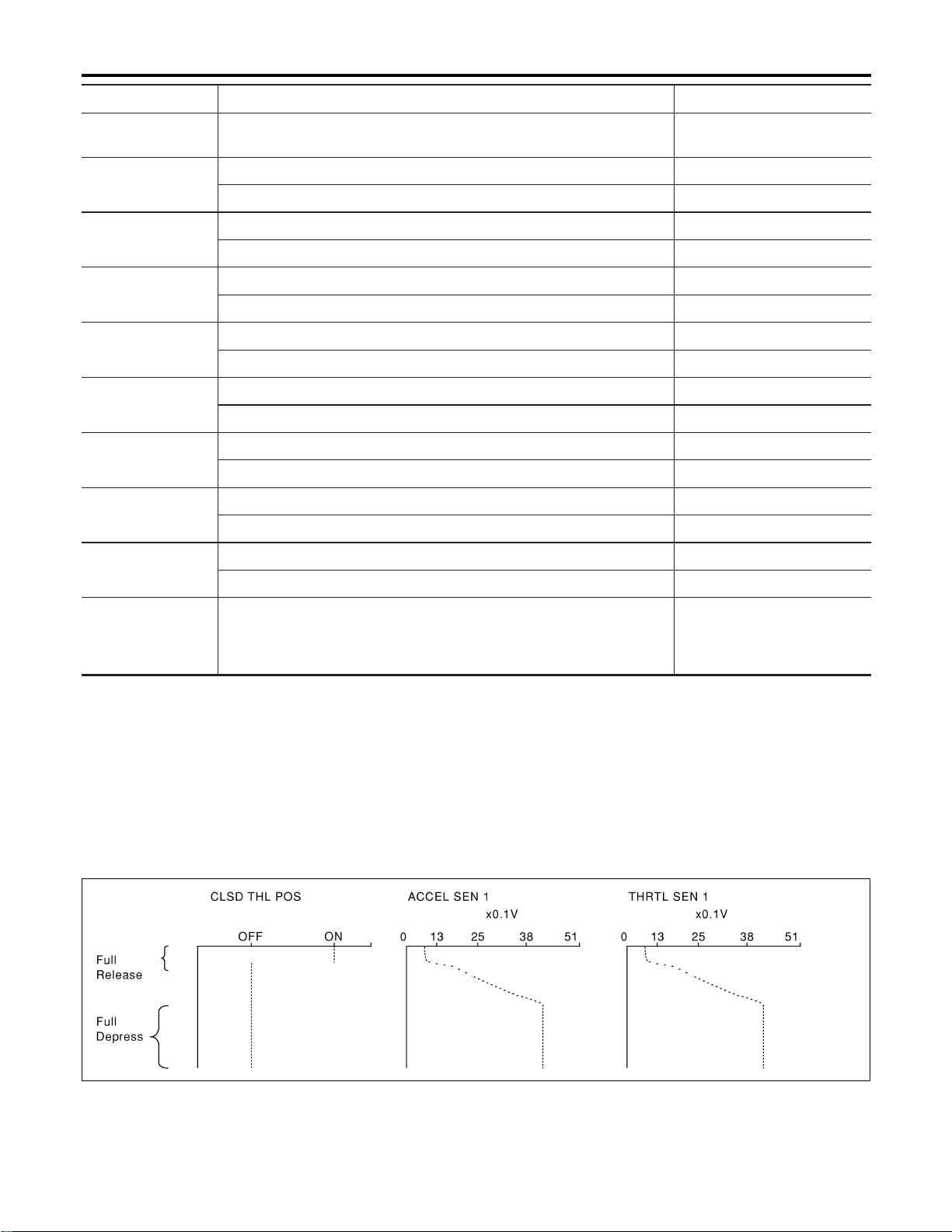
MONITOR ITEM CONDITION SPECIFICATION
SET VHCL SPD I ASCD set condition.
The preset vehicle speed is
displayed.
MAIN SW
I CRUISE switch is depressed. ON
I CRUISE switch is released. OFF
CANCEL SW
I CANCEL switch is depressed. ON
I CANCEL switch is released. OFF
RESUME/ACC SW
I ACCEL RES switch is depressed. ON
I ACCEL RES switch is released. OFF
SET SW
I SET switch is depressed. ON
I SET switch is released. OFF
BRAKE SW1
I Brake pedal is depressed. OFF
I Brake pedal is released. ON
BRAKE SW2
I Brake pedal is depressed. ON
I Brake pedal is released. OFF
CRUISE LAMP
I CRUISE lamp is indicated. ON
I CRUISE lamp is not indicated. OFF
SET LAMP
I SET lamp is indicated. ON
I SET lamp is not indicated. OFF
CAN COMM
CAN CIRC 1
CAN CIRC 2
CAN CIRC 3
I Ignition switch: ON OK
Major Sensor Reference Graph in Data Monitor
Mode
NFEC1427
The following are the major sensor reference graphs in “DATA MONITOR” mode.
CLSD THL POS, ACCEL SEN1, THRTL SEN1
NFEC1427S01
Below is the data for “CLSD THL POS”, “ACCEL SEN1” and “THRTL SEN1” when depressing the accelera-
tor pedal with the ignition switch “ON” and with selector lever in “D” position (AT models) or with shift lever in
“1st” position (MT models).
The signal of “ACCEL SEN1” and “THRTL SEN1” should rise gradually without any intermittent drop or rise
after “CLSD THL POS” is changed from “ON” to “OFF”.
SEC041D
TROUBLE DIAGNOSIS — GENERAL DESCRIPTION
CONSULT-II Reference Value in Data Monitor Mode (Cont’d)
EC-138
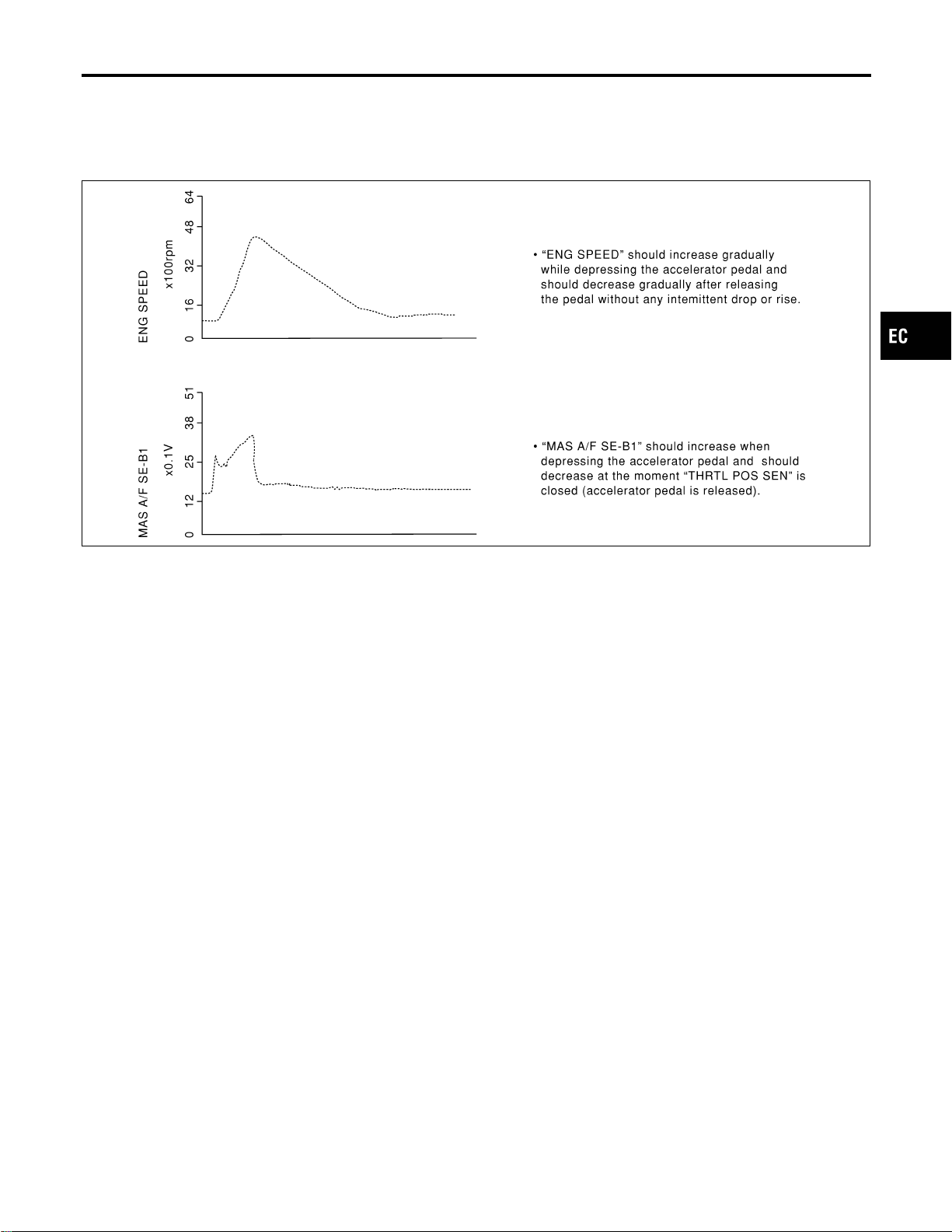
ENG SPEED, MAS A/F SE-B1, THRTL POS SEN, HO2S2 (B1), HO2S1 (B1), INJ PULSE-B1
NFEC1427S02
Below is the data for “ENG SPEED”, “MAS A/F SE-B1”, “THRTL POS SEN”, “HO2S2 (B1)”, “HO2S1 (B1)” and
“INJ PULSE-B1” when revving engine quickly up to 4,800 rpm under no load after warming up engine suffi-
ciently.
Each value is for reference, the exact value may vary.
SEF241Y
GI
MA
EM
LC
FE
CL
MT
AT
AX
SU
BR
ST
RS
BT
HA
SC
EL
IDX
TROUBLE DIAGNOSIS — GENERAL DESCRIPTION
Major Sensor Reference Graph in Data Monitor Mode (Cont’d)
EC-139
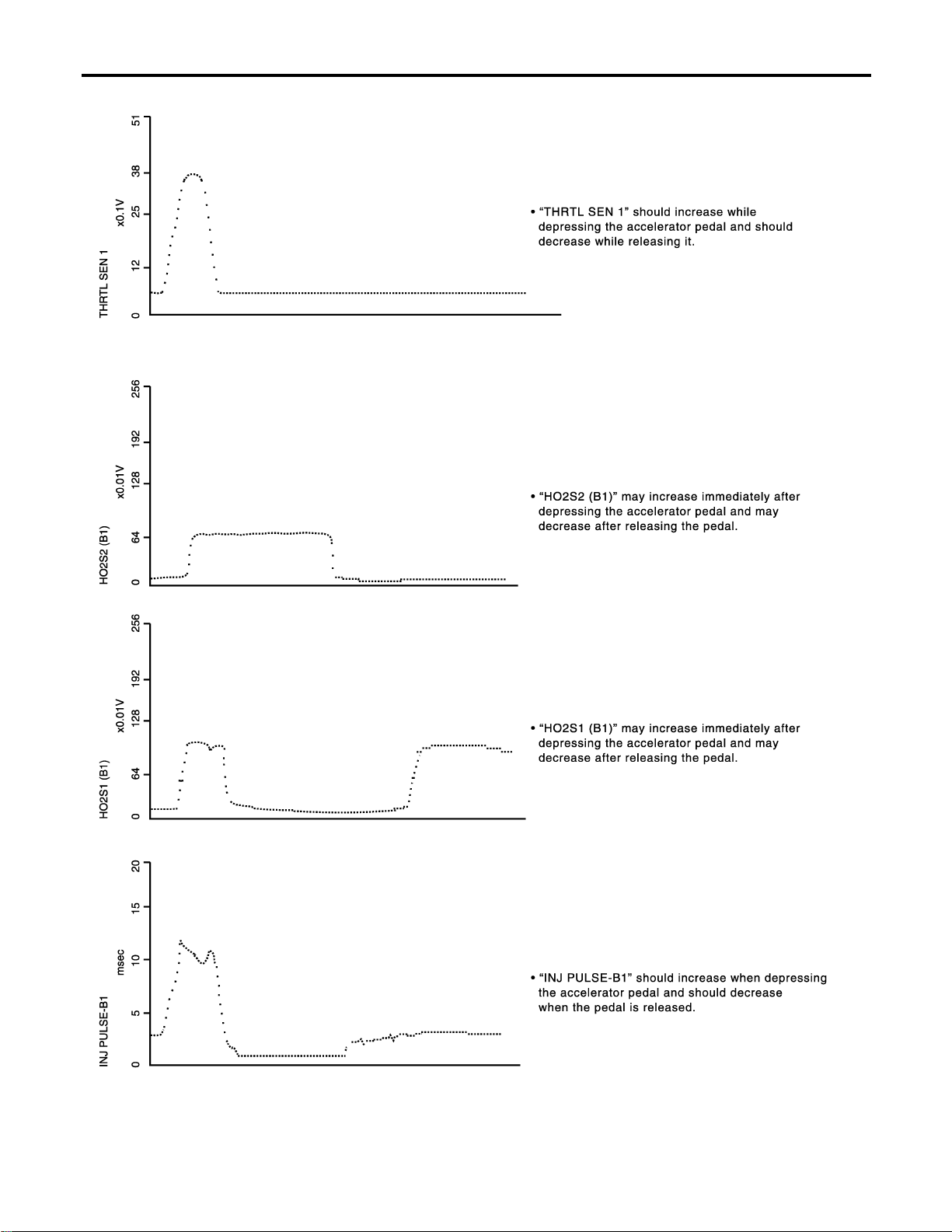
PBIB0668E
TROUBLE DIAGNOSIS — GENERAL DESCRIPTION
Major Sensor Reference Graph in Data Monitor Mode (Cont’d)
EC-140
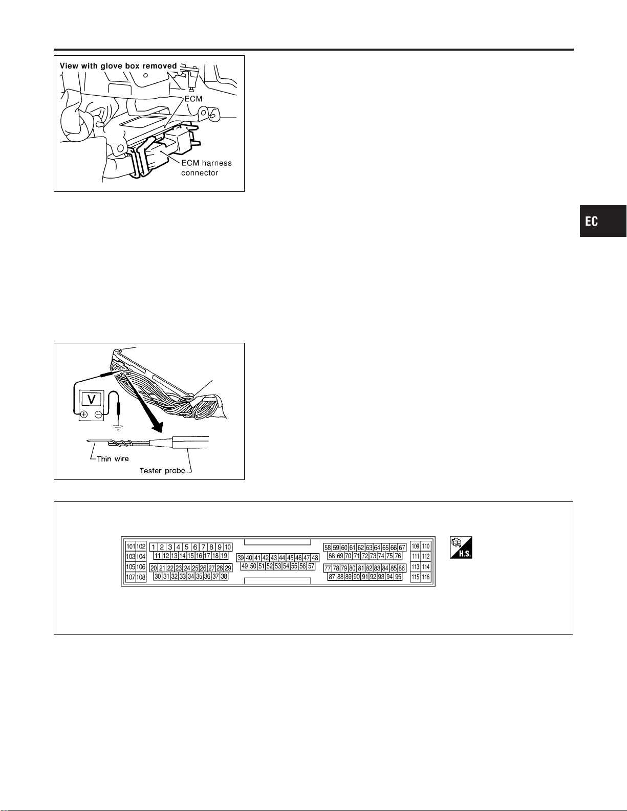
SEC042D
ECM Terminals and Reference Value
NFEC0044
PREPARATION
NFEC0044S01
1. ECM is located behind the instrument lower cover. For this
inspection, remove instrument lower cover.
2. Remove ECM harness protector.
MEC486B
3. Perform all voltage measurements with the connector con-
nected. Extend tester probe as shown to perform tests easily.
I Open harness securing clip to make testing easier.
I Use extreme care not to touch 2 pins at one time.
I Data is for comparison and may not be exact.
ECM HARNESS CONNECTOR TERMINAL LAYOUT
NFEC0044S02
SEF970W
ECM INSPECTION TABLE
NFEC0044S03
Specification data are reference values and are measured between
each terminal and ground.
Pulse signal is measured by CONSULT-II.
CAUTION:
Do not use ECM ground terminals when measuring the input/
output voltage. Doing so may result in damage to the ECM’s
transistor. Use ground other than the ECM terminals, such as
the ground.
GI
MA
EM
LC
FE
CL
MT
AT
AX
SU
BR
ST
RS
BT
HA
SC
EL
IDX
TROUBLE DIAGNOSIS — GENERAL DESCRIPTION
ECM Terminals and Reference Value
EC-141
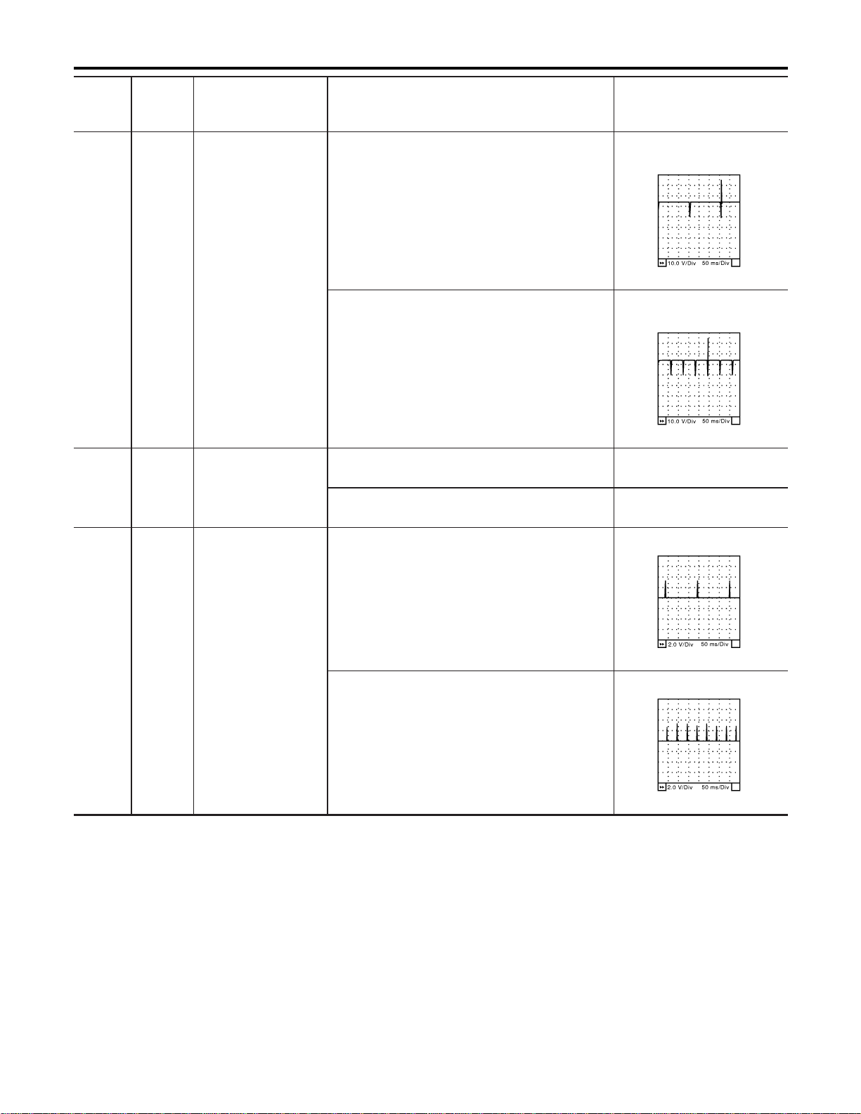
TERMI-
NAL
NO.
WIRE
COLOR
ITEM CONDITION DATA (DC Voltage)
1
2
3
11
12
13
R/B
R/W
R/Y
R/L
L/W
PU/R
Injector No. 1
Injector No. 2
Injector No. 3
Injector No. 4
Injector No. 5
Injector No. 6
[Engine is running]
I Warm-up condition
I Idle speed
BATTERY VOLTAGE
(11 - 14V)★
SEC984C
[Engine is running]
I Warm-up condition
I Engine speed is 2,000 rpm.
BATTERY VOLTAGE
(11 - 14V)★
SEC985C
4W
Electronic controlled
engine mount-1
[Engine is running]
I Idle speed
0-1V
[Engine is running]
I Except the above
BATTERY VOLTAGE
(11 - 14V)
5
6
7
15
16
17
Y/R
G/R
L/R
G/Y
PU/W
GY/R
Ignition signal No. 1
Ignition signal No. 2
Ignition signal No. 3
Ignition signal No. 4
Ignition signal No. 5
Ignition signal No. 6
[Engine is running]
I Warm-up condition
I Idle speed
0 - 0.2V★
SEC986C
[Engine is running]
I Warm-up condition
I Engine speed is 2,500 rpm.
0.1 - 0.3V★
SEC987C
TROUBLE DIAGNOSIS — GENERAL DESCRIPTION
ECM Terminals and Reference Value (Cont’d)
EC-142
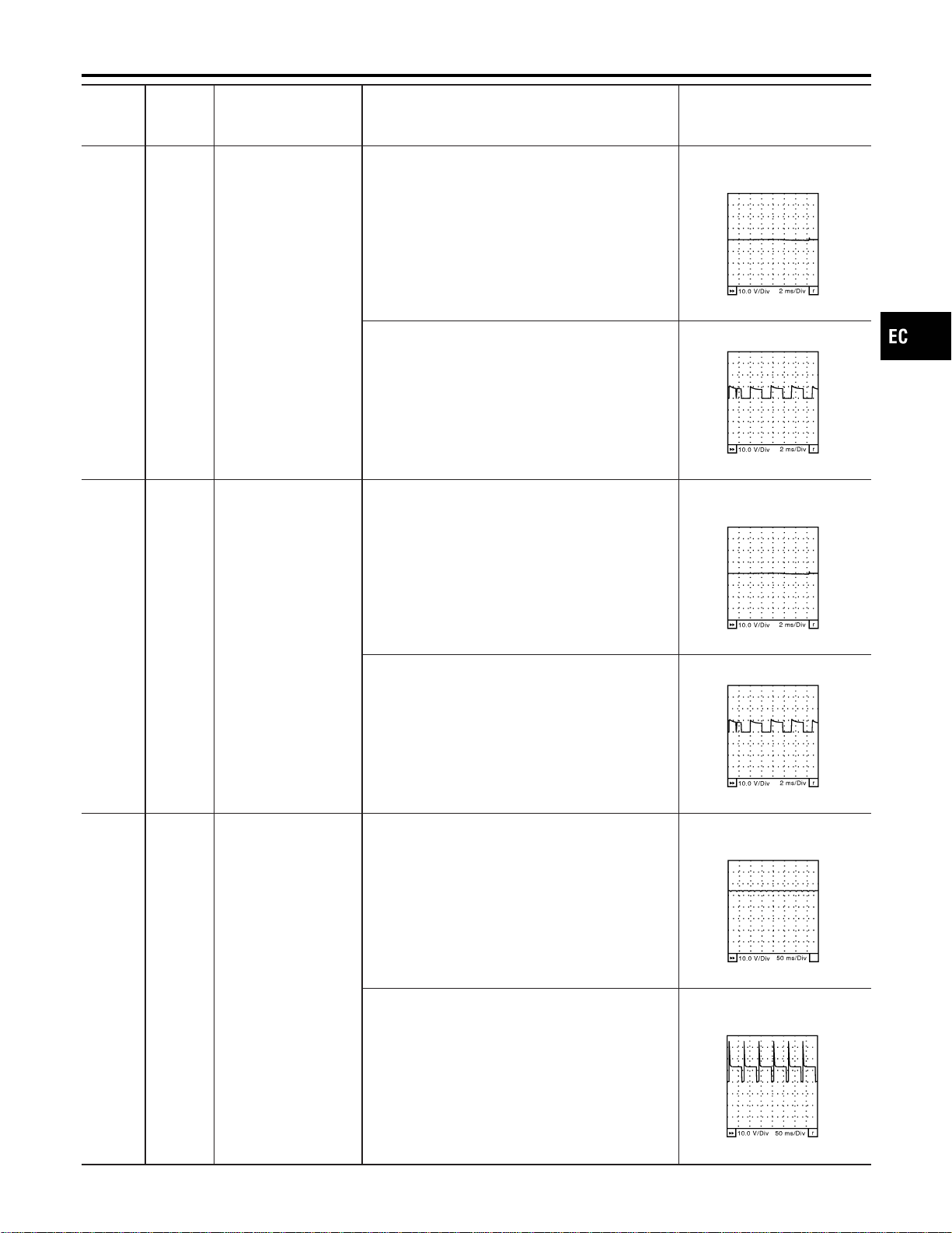
TERMI-
NAL
NO.
WIRE
COLOR
ITEM CONDITION DATA (DC Voltage)
8G
Intake valve timing
control solenoid valve
(bank 2)
[Engine is running]
I Warm-up condition
I Idle speed
BATTERY VOLTAGE
(11 - 14V)★
SEC988C
[Engine is running]
I Warm-up condition
I Engine speed is 2,500 rpm.
7 - 12V★
SEC989C
9 L/W
Intake valve timing
control solenoid valve
(bank 1)
[Engine is running]
I Warm-up condition
I Idle speed
BATTERY VOLTAGE
(11 - 14V)★
SEC988C
[Engine is running]
I Warm-up condition
I Engine speed is 2,500 rpm.
7 - 12V★
SEC989C
10 PU/R
EVAP canister purge
volume control sole-
noid valve
[Engine is running]
I Idle speed
BATTERY VOLTAGE
(11 - 14V)★
SEC990C
[Engine is running]
I Engine speed is 2,000 rpm (More than 100 sec-
onds after starting engine).
BATTERY VOLTAGE
(11 - 14V)★
SEC991C
GI
MA
EM
LC
FE
CL
MT
AT
AX
SU
BR
ST
RS
BT
HA
SC
EL
IDX
TROUBLE DIAGNOSIS — GENERAL DESCRIPTION
ECM Terminals and Reference Value (Cont’d)
EC-143

TERMI-
NAL
NO.
WIRE
COLOR
ITEM CONDITION DATA (DC Voltage)
14 W/R
Electronic controlled
engine mount-2
[Engine is running]
I Idle speed
BATTERY VOLTAGE
(11 - 14V)
[Engine is running]
I Except the above
0-1V
18 PU/W
Engine coolant tem-
perature sensor signal
output
[Engine is running]
I Idle speed
0 - 12V
Output voltage varies with
engine coolant temperature.
21 B/R Air conditioner relay
[Engine is running]
I Both A/C switch and blower switch are “ON”
(Compressor is operating).
0 - 1.0V
[Engine is running]
I A/C switch is “OFF”.
BATTERY VOLTAGE
(11 - 14V)
23 B/P Fuel pump relay
[Ignition switch “ON”]
I For 1 second after turning ignition switch “ON”
[Engine is running]
0 - 1.5V
[Ignition switch “ON”]
I 1 second pressed after turning ignition switch
“ON”
BATTERY VOLTAGE
(11 - 14V)
24 Y ASCD CRUISE lamp
[Ignition switch “ON”]
I CRUISE switch is “ON”.
0V
[Ignition switch “ON”]
I CRUISE switch is “OFF”.
BATTERY VOLTAGE
(11 - 14V)
25 R ASCD SET lamp
[Engine is running]
I SET switch is “ON”.
I ASCD control is operating.
0V
[Engine is running]
I SET or CRUISE switch is “OFF”.
I ASCD control is not operating.
BATTERY VOLTAGE
(11 - 14V)
26 O/R
Throttle control motor
relay
[Ignition switch “OFF”]
BATTERY VOLTAGE
(11 - 14V)
[Ignition switch “ON”] 0 - 1.0V
27 Y/G
VIAS control solenoid
valve
[Engine is running]
I Idle speed
BATTERY VOLTAGE
(11 - 14V)
[Engine is running]
I Engine speed is above 5,000 rpm.
0 - 1.0V
28 OR/G
Vacuum cut valve
bypass valve
[Ignition switch “ON”]
BATTERY VOLTAGE
(11 - 14V)
30 PU A/C cut signal
[Engine is running]
I Air conditioner is operating.
0 - 0.5V
31 R Counter current return [Ignition switch “ON”]
BATTERY VOLTAGE
(11 - 14V)
33 LG/B MIL
[Ignition switch “ON”] 0 - 1.0V
[Engine is running]
I Idle speed
BATTERY VOLTAGE
(11 - 14V)
TROUBLE DIAGNOSIS — GENERAL DESCRIPTION
ECM Terminals and Reference Value (Cont’d)
EC-144
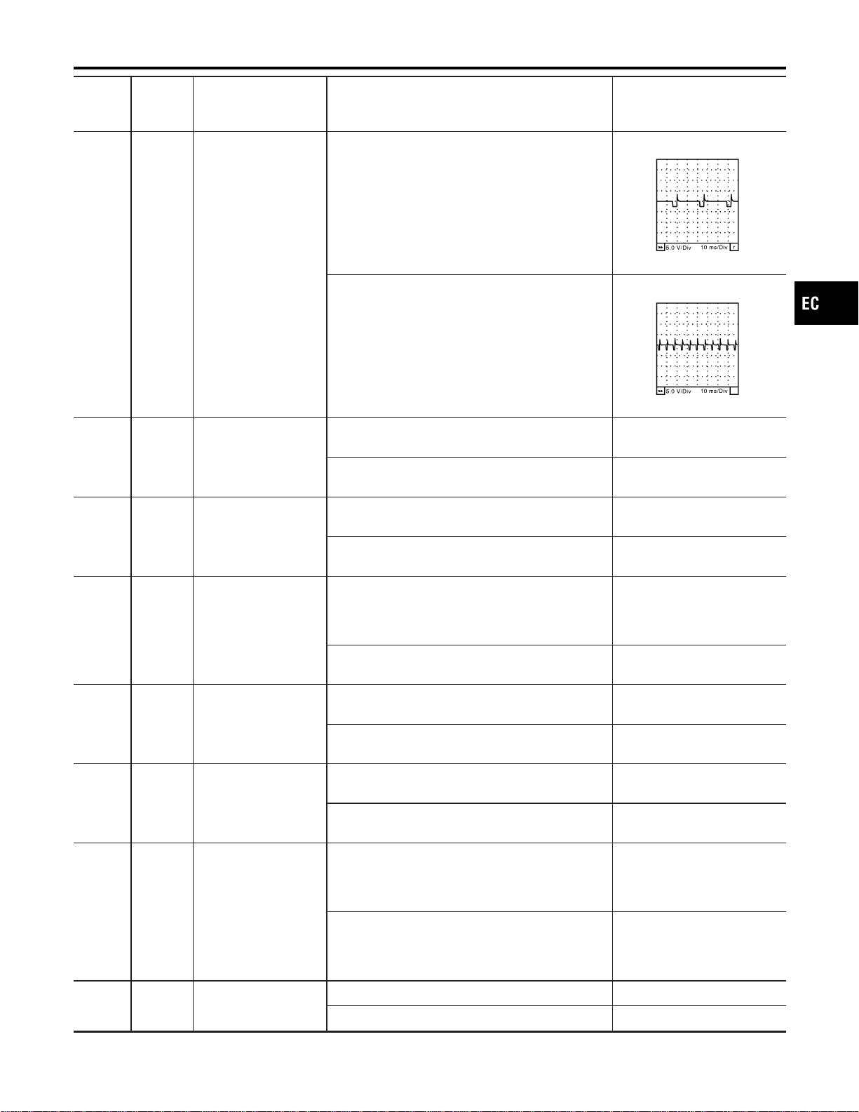
TERMI-
NAL
NO.
WIRE
COLOR
ITEM CONDITION DATA (DC Voltage)
34 W/G Tachometer
[Engine is running]
I Warm-up condition
I Idle speed
7-8V★
SEC992C
[Engine is running]
I Warm-up condition
I Engine speed is 2,500 rpm.
7-8V★
SEC032D
35 BR/R
Cooling fan relay
(LOW)
[Engine is running]
I Cooling fan is operating.
0 - 1.0V
[Engine is running]
I Cooling fan is not operating.
BATTERY VOLTAGE
(11 - 14V)
36 LG
Cooling fan relay
(HIGH)
[Engine is running]
I Cooling fan is operating at high speed.
0 - 1.0V
[Engine is running]
I Cooling fan is not operating.
BATTERY VOLTAGE
(11 - 14V)
38 W/B
ECM relay
(Self shut-off)
[Engine is running]
[Ignition switch “ON”]
I For a few seconds after turning ignition switch
“OFF”
0 - 1.5V
[Ignition switch “ON”]
I A few seconds after turning ignition switch “OFF”
BATTERY VOLTAGE
(11 - 14V)
39 OR/L
Heated oxygen sensor
1 heater (bank 1)
[Engine is running]
I Engine speed is below 3,600 rpm.
0 - 0.5V
[Engine is running]
I Engine speed is above 3,600 rpm.
BATTERY VOLTAGE
(11 - 14V)
40 R/L
Heated oxygen sensor
1 heater (bank 2)
[Engine is running]
I Engine speed is below 3,600 rpm.
0 - 0.5V
[Engine is running]
I Engine speed is above 3,600 rpm.
BATTERY VOLTAGE
(11 - 14V)
41 P/B
Heated oxygen sensor
2 heater (bank 1)
[Engine is running]
I Engine speed is below 3,600 rpm.
I After driving for 2 minutes at a speed of 70 km/h
(43 MPH) or more
0 - 0.5V
[Ignition switch “ON”]
I Engine stopped
[Engine is running]
I Engine speed is above 3,600 rpm.
BATTERY VOLTAGE
(11 - 14V)
42 BR/W Start signal
[Ignition switch “ON”] Approximately 0V
[Ignition switch “START”] 9 - 12V
GI
MA
EM
LC
FE
CL
MT
AT
AX
SU
BR
ST
RS
BT
HA
SC
EL
IDX
TROUBLE DIAGNOSIS — GENERAL DESCRIPTION
ECM Terminals and Reference Value (Cont’d)
EC-145

TERMI-
NAL
NO.
WIRE
COLOR
ITEM CONDITION DATA (DC Voltage)
43 R Ignition switch
[Ignition switch “OFF”] 0V
[Ignition switch “ON”]
BATTERY VOLTAGE
(11 - 14V)
44 G/OR PNP switch
[Ignition switch “ON”]
I General position is “P” or “N”.
Approximately 0V
[Ignition switch “ON”]
I Except the above gear position
BATTERY VOLTAGE
(11 - 14V)
45 G/B
Air conditioner switch
signal
[Engine is running]
I Both A/C switch and blower switch are “ON”.
Approximately 0V
[Engine is running]
I A/C switch is “OFF”.
BATTERY VOLTAGE
(11 - 14V)
47 R/L
Heated oxygen sensor
2 heater (bank 2)
[Engine is running]
I Engine speed is below 3,600 rpm.
I After driving for 2 minutes at a speed of 70 km/h
(43 MPH) or more
0 - 0.5V
[Ignition switch “ON”]
I Engine stopped
[Engine is running]
I Engine speed is above 3,600 rpm.
BATTERY VOLTAGE
(11 - 14V)
48 B ECM ground
[Engine is running]
I Idle speed
Engine ground
50 G/Y ASCD steering switch
[Ignition switch “ON”] Approximately 4.0V
[Ignition switch “ON”]
I CRUISE switch is “ON”.
Approximately 0V
[Ignition switch “ON”]
I CANCEL switch is “ON”.
Approximately 1.0V
[Ignition switch “ON”]
I ACCEL RES switch is “ON”.
Approximately 3.0V
[Ignition switch “ON”]
I COAST/SET switch is “ON”.
Approximately 2.0V
51 W/G Electrical load signal
[Engine is running]
I Rear window defogger: ON
I Hi-beam headlamp: ON
BATTERY VOLTAGE
(11 - 14V)
[Engine is running]
I Electrical load: OFF
0V
55 R/G Stop lamp switch
Brake pedal is depressed.
BATTERY VOLTAGE
(11 - 14V)
Brake pedal is released. 0V
57 B ECM ground
[Engine is running]
I Idle speed
Engine ground
58 B Sensors’ ground
[Engine is running]
I Warm-up condition
I Idle speed
Approximately 0V
TROUBLE DIAGNOSIS — GENERAL DESCRIPTION
ECM Terminals and Reference Value (Cont’d)
EC-146
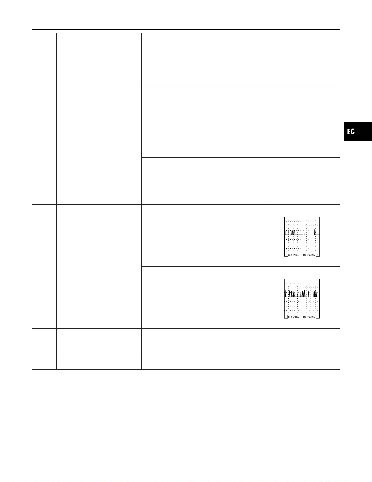
TERMI-
NAL
NO.
WIRE
COLOR
ITEM CONDITION DATA (DC Voltage)
59 G/B ASCD brake switch
[Ignition switch “ON”]
I Gear position is “P” or “N” (A/T models).
I Brake pedal is depressed.
I Clutch pedal is depressed (M/T models).
0V
[Ignition switch “ON”]
I Gear position is except “P” or “N” (A/T models).
I Brake pedal is released.
I Clutch pedal is released (M/T models).
BATTERY VOLTAGE
(11 - 14V)
60 W
EVAP control system
pressure sensor
[Ignition switch “ON”] Approximately 3.4V
62 W Mass air flow sensor
[Engine is running]
I Warm-up condition
I Idle speed
1.1 - 1.5V
[Engine is running]
I Warm-up condition
I Engine speed is 2,500 rpm.
1.7 - 2.4V
64 OR
Accelerator pedal posi-
tion sensor 2 power
supply
[Ignition switch “ON”] Approximately 2.5V
65 Y
Camshaft position sen-
sor (PHASE) (bank 1)
[Engine is running]
I Warm-up condition
I Idle speed
1.0 - 4.0V★
SEC033D
[Engine is running]
I Engine speed is 2,000 rpm.
1.0 - 4.0V★
SEC034D
66 Y/G
Mass air flow sensor
(Intake air temperature
sensor)
[Engine is running]
Approximately 0 - 4.8V
Output voltage varies with
intake air temperature.
67 W/L
Power supply for ECM
(Back-up)
[Ignition switch “OFF”]
BATTERY VOLTAGE
(11 - 14V)
GI
MA
EM
LC
FE
CL
MT
AT
AX
SU
BR
ST
RS
BT
HA
SC
EL
IDX
TROUBLE DIAGNOSIS — GENERAL DESCRIPTION
ECM Terminals and Reference Value (Cont’d)
EC-147
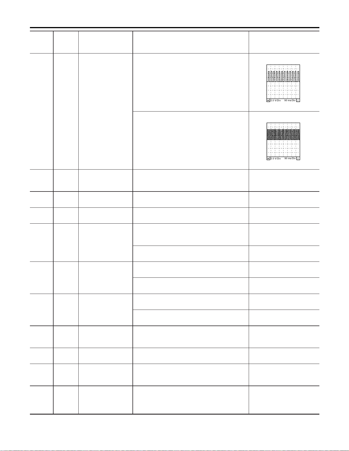
TERMI-
NAL
NO.
WIRE
COLOR
ITEM CONDITION DATA (DC Voltage)
68 P/L Vehicle speed sensor
[Engine is running]
I Jack-up front wheels
I In 1st gear position
I 10 km/h (6 MPH)
Approximately 2.5V★
SEC039D
[Engine is running]
I Jack-up front wheels
I In 2nd gear position
I 30 km/h (19 MPH)
Approximately 2.0V★
SEC040D
69 G Fuel level sensor [Ignition switch “ON”]
Approximately 0 - 4.8V
Output voltage varies with
fuel level.
70 B/P
Accelerator pedal posi-
tion sensor 2 ground
[Ignition switch “ON”] Approximately 0V
71 W Knock sensor
[Engine is running]
I Idle speed
Approximately 2.5V
72 W
Accelerator pedal posi-
tion sensor signal out-
put
[Engine is running]
I Warm-up condition
I Accelerator pedal fully released
Approximately 0.6V
[Ignition switch “ON”]
I Accelerator pedal fully depressed
Approximately 4.0V
73 W
Accelerator pedal posi-
tion sensor 1
[Ignition switch “ON”]
I Accelerator pedal fully released
0.41 - 0.71V
[Ignition switch “ON”]
I Accelerator pedal fully depressed
More than 3.7V
74 W/B
Accelerator pedal posi-
tion sensor 2
[Ignition switch “ON”]
I Accelerator pedal fully released
0.08 - 0.48V
[Ignition switch “ON”]
I Accelerator pedal fully depressed
More than 1.8V
75 P/L
Fuel tank temperature
sensor
[Engine is running]
Approximately 0 - 4.8V
Output voltage varies with
fuel tank temperature.
78 B
Fuel level sensor
ground
[Engine is running]
I Idle speed
Approximately 0V
80 B
Mass air flow sensor
ground
[Engine is running]
I Warm-up condition
I Idle speed
Approximately 0V
81 W
Refrigerant pressure
sensor
[Engine is running]
I Warm-up condition
I Both A/C switch and blower switch are “ON”.
(Compressor operates.)
1.0 - 4.0V
TROUBLE DIAGNOSIS — GENERAL DESCRIPTION
ECM Terminals and Reference Value (Cont’d)
EC-148
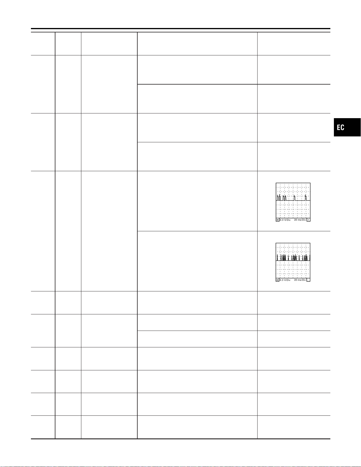
TERMI-
NAL
NO.
WIRE
COLOR
ITEM CONDITION DATA (DC Voltage)
83 W
Throttle position sensor
1
[Ignition switch “ON”]
I Gear position is “D” (A/T model)
I Shift lever position is “1st” (M/T model)
I Accelerator pedal fully released
More than 0.36V
[Ignition switch “ON”]
I Gear position is “D” (A/T model)
I Shift lever position is “1st” (M/T model)
I Accelerator pedal fully depressed
Less than 4.75V
84 L
Throttle position sensor
2
[Ignition switch “ON”]
I Gear position is “D” (A/T model)
I Shift lever position is “1st” (M/T model)
I Accelerator pedal fully released
Less than 4.75V
[Ignition switch “ON”]
I Gear position is “D” (A/T model)
I Shift lever position is “1st” (M/T model)
I Accelerator pedal fully depressed
More than 0.36V
85 R
Camshaft position sen-
sor (PHASE) (bank 2)
[Engine is running]
I Warm-up condition
I Idle speed
1.0 - 4.0V★
SEC033D
[Engine is running]
I Engine speed is 2,000 rpm.
1.0 - 4.0V★
SEC034D
88 W
Heated oxygen sensor
2 (bank 1)
[Engine is running]
I Warm-up condition
I Engine speed is 2,000 rpm.
0 - Approximately 1.0V
89 G
Power steering pres-
sure sensor
[Engine is running]
I Steering wheel is being turned.
0 - 1.0V
[Engine is running]
I Steering wheel is not being turned.
BATTERY VOLTAGE
(11 - 14V)
90 W
Heated oxygen sensor
2 (bank 2)
[Engine is running]
I Warm-up condition
I Engine speed is 2,000 rpm.
0 - Approximately 1.0V
91 W
Heated oxygen sensor
1 (bank 1)
[Engine is running]
I Warm-up condition
I Engine speed is 2,000 rpm.
0 - Approximately 1.0V
(Periodically change)
92 W
Heated oxygen sensor
1 (bank 2)
[Engine is running]
I Warm-up condition
I Engine speed is 2,000 rpm.
0 - Approximately 1.0V
(Periodically change)
93 Y
Engine coolant tem-
perature sensor
[Engine is running]
Approximately 0 - 4.8V
Output voltage varies with
engine coolant temperature.
GI
MA
EM
LC
FE
CL
MT
AT
AX
SU
BR
ST
RS
BT
HA
SC
EL
IDX
TROUBLE DIAGNOSIS — GENERAL DESCRIPTION
ECM Terminals and Reference Value (Cont’d)
EC-149
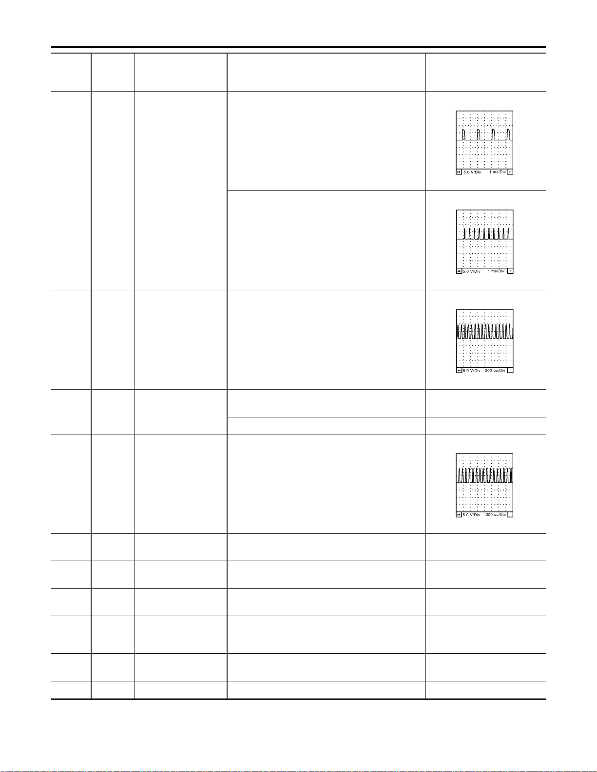
TERMI-
NAL
NO.
WIRE
COLOR
ITEM CONDITION DATA (DC Voltage)
95 W
Crankshaft position
sensor (POS)
[Engine is running]
I Idle speed
Approximately 2.4V★
SEC035D
[Engine is running]
I Engine speed is 2,000 rpm.
Approximately 2.3V★
SEC036D
101 Y
Throttle control motor
(Open)
[Ignition switch “ON”]
I Gear position is “D” (A/T model)
I Shift lever position is “1st” (M/T model)
I Accelerator pedal fully depressed
0-5V★
SEC037D
102 R
Throttle control motor
relay
[Ignition switch “ON”]
BATTERY VOLTAGE
(11 - 14V)
[Ignition switch “OFF”] 0 - 1.0V
103 BR
Throttle control motor
(Close)
[Ignition switch “ON”]
I Gear position is “D” (A/T model)
I Shift lever position is “1st” (M/T model)
I Accelerator pedal fully released
0-3V★
SEC038D
105 OR/L
EVAP canister vent
control valve
[Ignition switch “ON”]
BATTERY VOLTAGE
(11 - 14V)
106
108
B
B
ECM ground
[Engine is running]
I Idle speed
Engine ground
107 B
Throttle control motor
ground
[Ignition switch “ON”] Approximately 0V
109 L
CAN communication
line
[Ignition switch “ON”]
Approximately 2.6 - 3.2V
Output voltage varies with the
communication status.
110
112
R/G
R/G
Power supply for ECM [Ignition switch “ON”]
BATTERY VOLTAGE
(11 - 14V)
111 R Sensors’ power supply [Ignition switch “ON”] Approximately 5V
TROUBLE DIAGNOSIS — GENERAL DESCRIPTION
ECM Terminals and Reference Value (Cont’d)
EC-150
TERMI-
NAL
NO.
WIRE
COLOR
ITEM CONDITION DATA (DC Voltage)
113 R
CAN communication
line
[Ignition switch “ON”]
Approximately 1.7 - 2.3V
Output voltage varies with the
communication status.
115 OR Data link connector
[Ignition switch “ON”]
I CONSULT-II or GST is disconnected.
BATTERY VOLTAGE
(11 - 14V)
★: Average voltage for pulse signal (Actual pulse signal can be confirmed by oscilloscope.)
GI
MA
EM
LC
FE
CL
MT
AT
AX
SU
BR
ST
RS
BT
HA
SC
EL
IDX
TROUBLE DIAGNOSIS — GENERAL DESCRIPTION
ECM Terminals and Reference Value (Cont’d)
EC-151
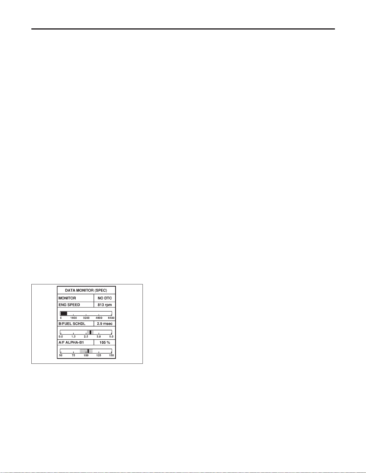
Description
NFEC0717
The specification (SP) value indicates the tolerance of the value that is displayed in “DATAMONITOR (SPEC)”
mode of CONSULT-II during normal operation of the Engine Control System. When the value in “DATA MONI-
TOR (SPEC)” mode is within the SP value, the Engine Control System is confirmed OK. When the value in
“DATA MONITOR (SPEC)” mode is NOT within the SP value, the Engine Control System may have one or
more malfunctions.
The SP value is used to detect malfunctions that may affect the Engine Control System, but will not light the
MIL.
The SP value will be displayed for the following three items:
I B/FUEL SCHDL (The fuel injection pulse width programmed into ECM prior to any learned on board cor-
rection)
I A/F ALPHA-B1/B2 (The mean value of air-fuel ratio feedback correction factor per cycle)
I MAS A/F SE-B1 (The signal voltage of the mass air flow sensor)
Testing Condition
NFEC0718
I Vehicle driven distance: More than 5,000 km (3,107 miles)
I Barometric pressure: 98.3 - 104.3 kPa (1.003 - 1.064 kg/cm
2
, 14.25 - 15.12 psi)
I Atmospheric temperature: 20 - 30°C (68 - 86°F)
I Engine coolant temperature: 75 - 95°C (167 - 203°F)
I Transmission: Warmed-up*1
I Electrical load: Not applied*2
I Engine speed: Idle
*1: For A/T models, after the engine is warmed up to normal operating temperature, drive vehicle until “FLUID
TEMP SE” (A/T fluid temperature sensor signal) indicates less than 0.9V. For M/T models, drive vehicle for 10
minutes after the engine is warmed up to normal operating temperature.
*2: Rear window defogger switch, air conditioner switch, lighting switch are “OFF”. Cooling fans are not oper-
ating. Steering wheel is straight ahead.
SEF601Z
Inspection Procedure
NFEC0719
NOTE:
Perform “DATA MONITOR (SPEC)” mode in maximum scale dis-
play.
1. Perform “Basic Inspection”, EC-123.
2. Confirm that the testing conditions indicated above are met.
3. Select “B/FUEL SCHDL”, “A/F ALPHA-B1”, “A/F ALPHA-B2”
and “MASA/F SE-B1” in “DATA MONITOR (SPEC)” mode with
CONSULT-II.
4. Make sure that monitor items are within the SP value.
5. If NG, go to “Diagnostic Procedure”, EC-153.
TROUBLE DIAGNOSIS — SPECIFICATION VALUE
Description
EC-152
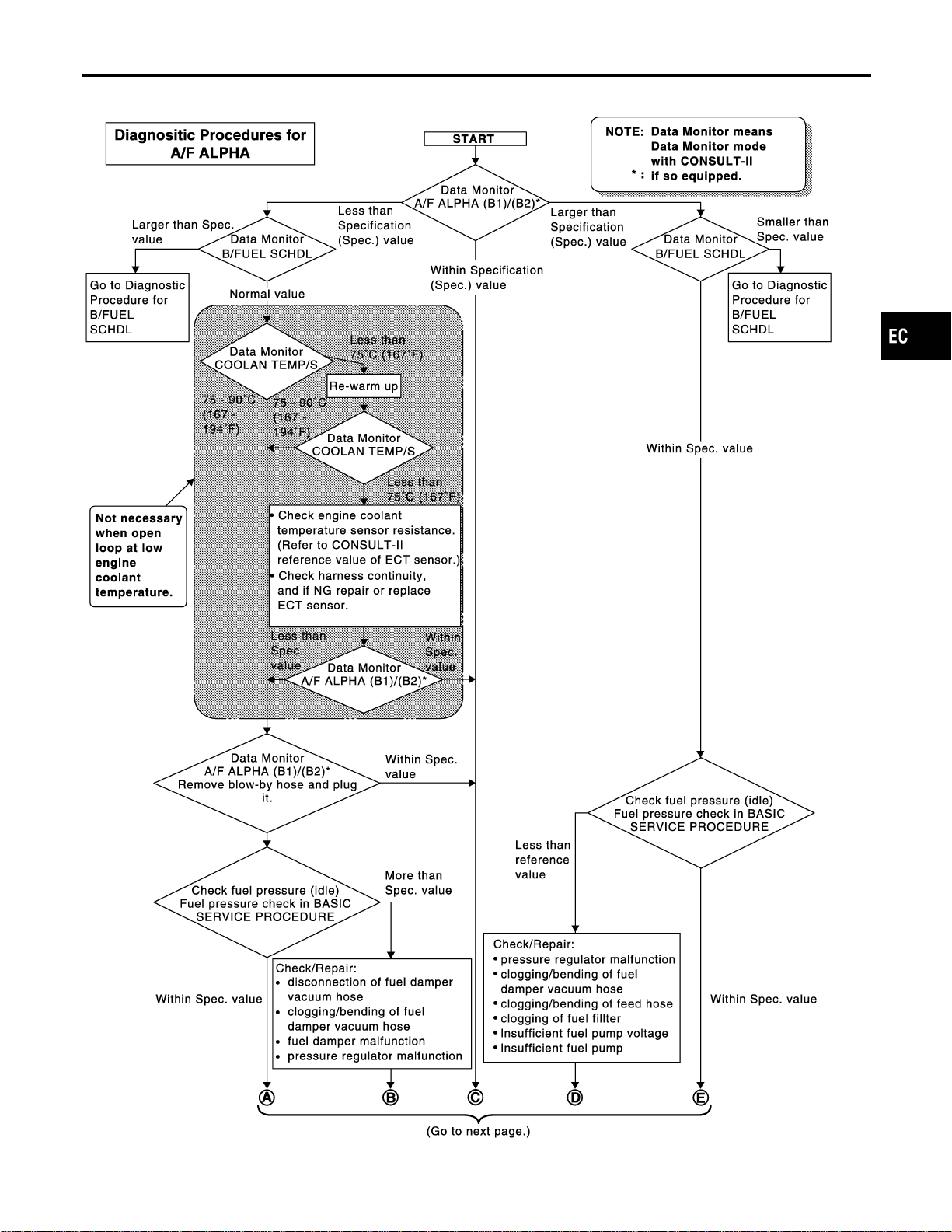
Diagnostic Procedure
NFEC0720
SEF613ZD
GI
MA
EM
LC
FE
CL
MT
AT
AX
SU
BR
ST
RS
BT
HA
SC
EL
IDX
TROUBLE DIAGNOSIS — SPECIFICATION VALUE
Diagnostic Procedure
EC-153
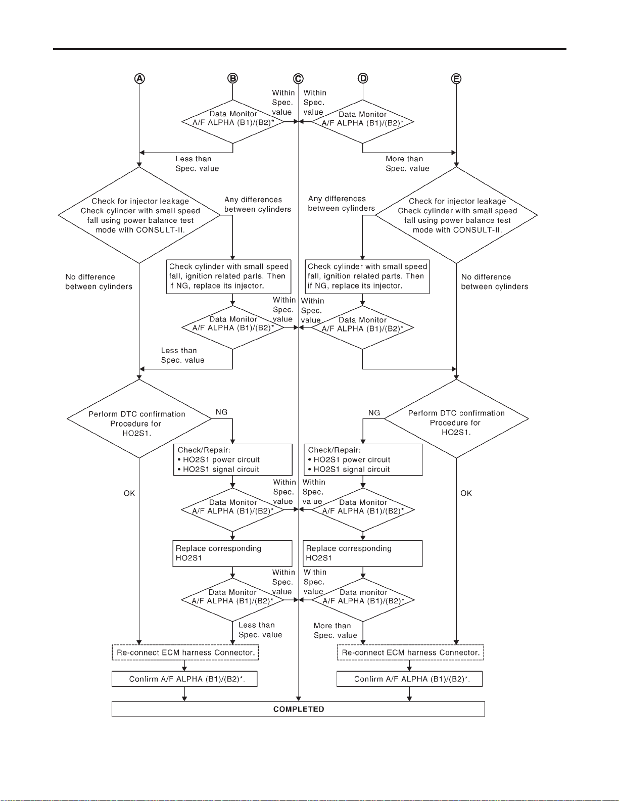
SEF768Z
TROUBLE DIAGNOSIS — SPECIFICATION VALUE
Diagnostic Procedure (Cont’d)
EC-154
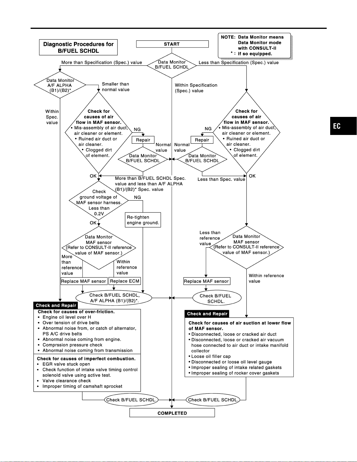
SEF615ZA
GI
MA
EM
LC
FE
CL
MT
AT
AX
SU
BR
ST
RS
BT
HA
SC
EL
IDX
TROUBLE DIAGNOSIS — SPECIFICATION VALUE
Diagnostic Procedure (Cont’d)
EC-155
Description
NFEC0045
Intermittent incidents (I/I) may occur. In many cases, the problem resolves itself (the part or circuit function
returns to normal without intervention). It is important to realize that the symptoms described in the custom-
er’s complaint often do not recur on (1st trip) DTC visits. Realize also that the most frequent cause of I/I
occurrences is poor electrical connections. Because of this, the conditions under which the incident occurred
may not be clear. Therefore, circuit checks made as part of the standard diagnostic procedure may not indi-
cate the specific problem area.
COMMON I/I REPORT SITUATIONS
NFEC0045S01
STEP in Work Flow Situation
II The CONSULT-II is used. The SELF-DIAG RESULTS screen shows time data other than “0” or “[1t]”.
III The symptom described by the customer does not recur.
IV (1st trip) DTC does not appear during the DTC Confirmation Procedure.
VI The Diagnostic Procedure for PXXXX does not indicate the problem area.
Diagnostic Procedure
NFEC0046
1 INSPECTION START
Erase (1st trip) DTCs. Refer to “HOW TO ERASE EMISSION — RELATED INFORMATION”, EC-91.
© GO TO 2.
2 CHECK GROUND TERMINALS
Check ground terminals for corroding or loose connection.
Refer to GI-30, “GROUND INSPECTION”.
OK or NG
OK © GO TO 3.
NG © Repair or replace.
3 SEARCH FOR ELECTRICAL INCIDENT
Perform GI-25, “Incident Simulation Tests”.
OK or NG
OK © GO TO 4.
NG © Repair or replace.
4 CHECK CONNECTOR TERMINALS
Refer to GI-22, “How to Check Enlarged Contact Spring of Terminal”.
OK or NG
OK © INSPECTION END
NG © Repair or replace connector.
TROUBLE DIAGNOSIS FOR INTERMITTENT INCIDENT
Description
EC-156
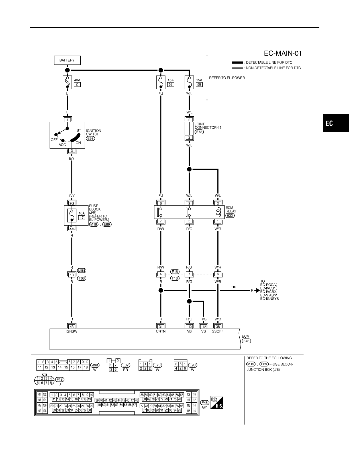
Main Power Supply and Ground Circuit
WIRING DIAGRAM
NFEC0047
MEC922D
GI
MA
EM
LC
FE
CL
MT
AT
AX
SU
BR
ST
RS
BT
HA
SC
EL
IDX
TROUBLE DIAGNOSIS FOR POWER SUPPLY
Main Power Supply and Ground Circuit
EC-157
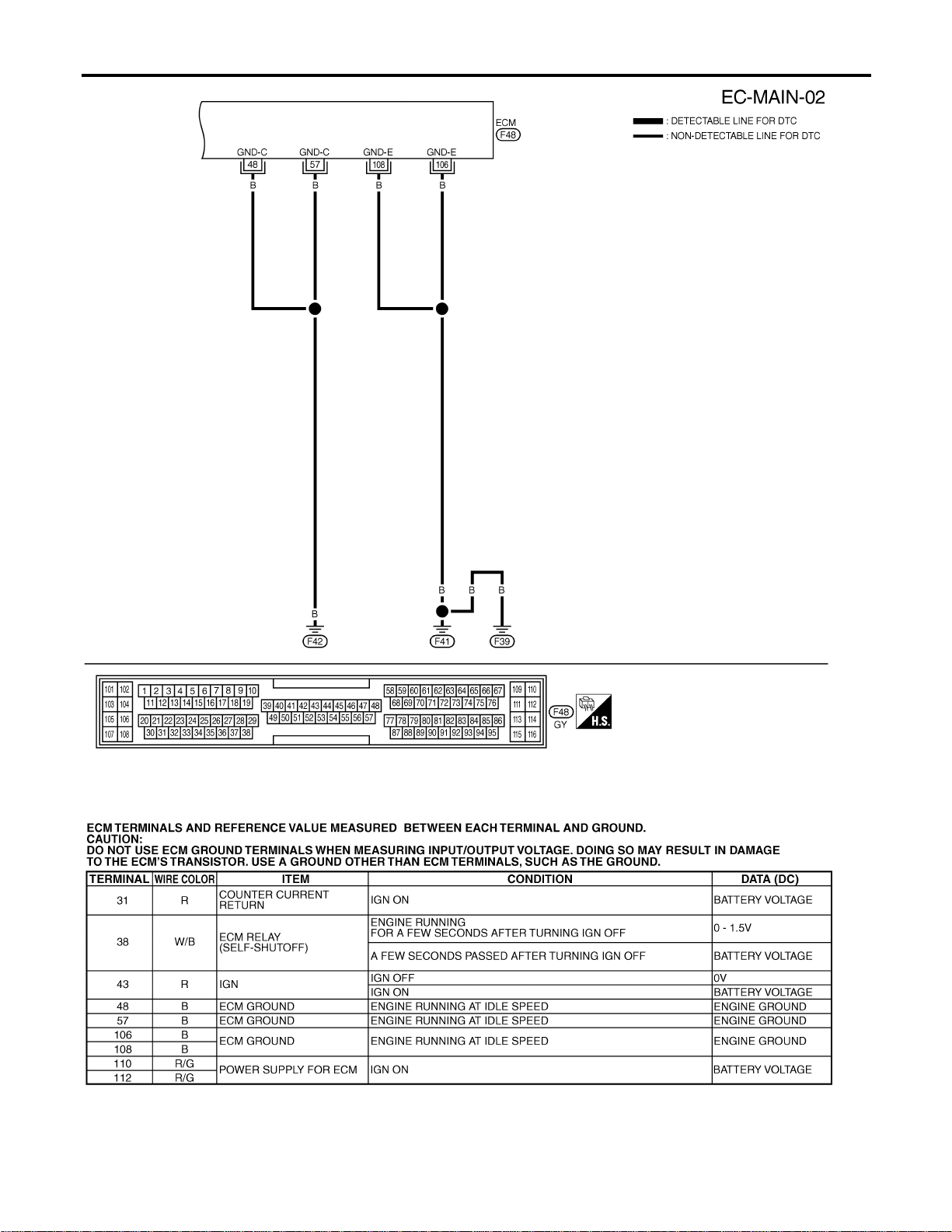
MEC472D
SEC043D
TROUBLE DIAGNOSIS FOR POWER SUPPLY
Main Power Supply and Ground Circuit (Cont’d)
EC-158
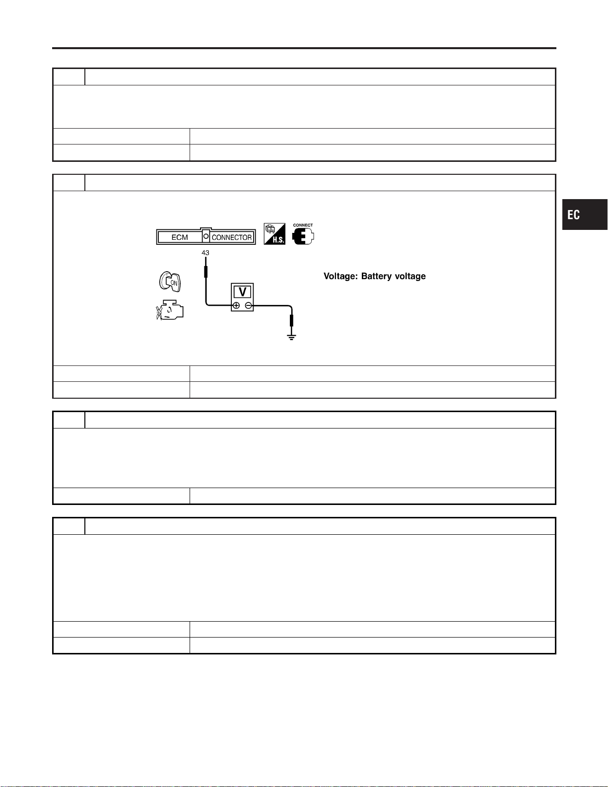
DIAGNOSTIC PROCEDURE
NFEC0049
1 INSPECTION START
Start engine.
Is engine running?
YesorNo
Yes © GO TO 9.
No © GO TO 2.
2 CHECK ECM POWER SUPPLY CIRCUIT-I
1. Turn ignition switch “OFF” and then “ON”.
2. Check voltage between ECM terminal 43 and ground with CONSULT-II or tester.
SEF291X
OK or NG
OK © GO TO 4.
NG © GO TO 3.
3 DETECT MALFUNCTIONING PART
Check the following.
I 10A fuse
I Harness connectors M161, F68
I Fuse block (J/B) connectors M19, E89
I Harness for open or short between ECM and ignition switch
© Repair harness or connectors.
4 CHECK ECM GROUND CIRCUIT FOR OPEN AND SHORT-I
1. Turn ignition switch “OFF”.
2. Disconnect ECM harness connector.
3. Check harness continuity between ECM terminals 48, 57, 106, 108 and engine ground.
Refer to WIRING DIAGRAM.
Continuity should exist.
4. Also check harness for short to power.
OK or NG
OK © GO TO 5.
NG © Repair open circuit or short to power in harness or connectors.
GI
MA
EM
LC
FE
CL
MT
AT
AX
SU
BR
ST
RS
BT
HA
SC
EL
IDX
TROUBLE DIAGNOSIS FOR POWER SUPPLY
Main Power Supply and Ground Circuit (Cont’d)
EC-159
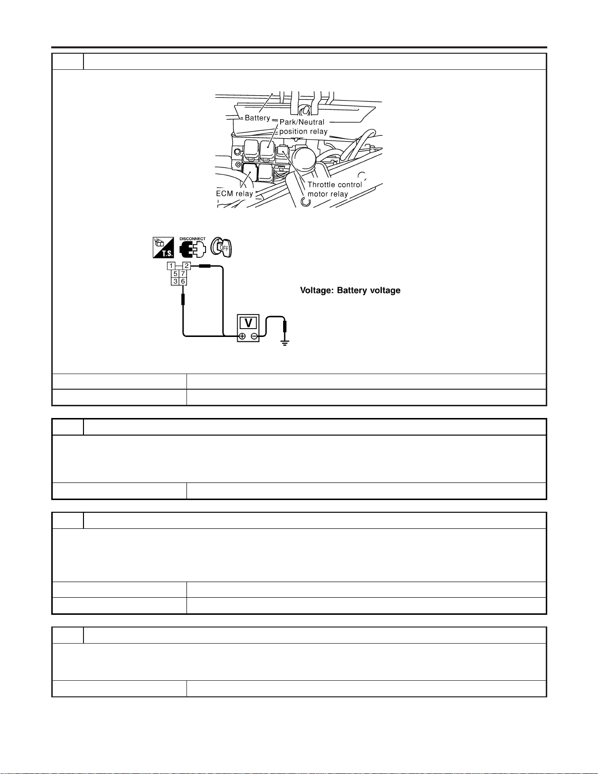
5 CHECK POWER SUPPLY-II
1. Disconnect ECM relay.
SEC044D
2. Check voltage between ECM relay terminals 2, 6 and ground with CONSULT-II or tester.
SEF292X
OK or NG
OK © GO TO 7.
NG © GO TO 6.
6 DETECT MALFUNCTIONING PART
Check the following.
I 15A fuses
I Joint connector-12
I Harness for open or short between ECM relay and battery
© Repair open circuit or short to ground or short to power in harness or connectors.
7 CHECK OUTPUT SIGNAL CIRCUIT FOR OPEN AND SHORT
1. Check harness continuity between ECM terminal 38 and ECM relay terminal 1. Refer to WIRING DIAGRAM.
Continuity should exist.
2. Also check harness for short to ground and short to power.
OK or NG
OK © Go to “IGNITION SIGNAL”, EC-692.
NG © GO TO 8.
8 DETECT MALFUNCTIONING PART
Check the following.
I Harness connectors E15, F18
I Harness for open or short between ECM relay and ECM
© Repair open circuit or short to ground or short to power in harness or connectors.
TROUBLE DIAGNOSIS FOR POWER SUPPLY
Main Power Supply and Ground Circuit (Cont’d)
EC-160
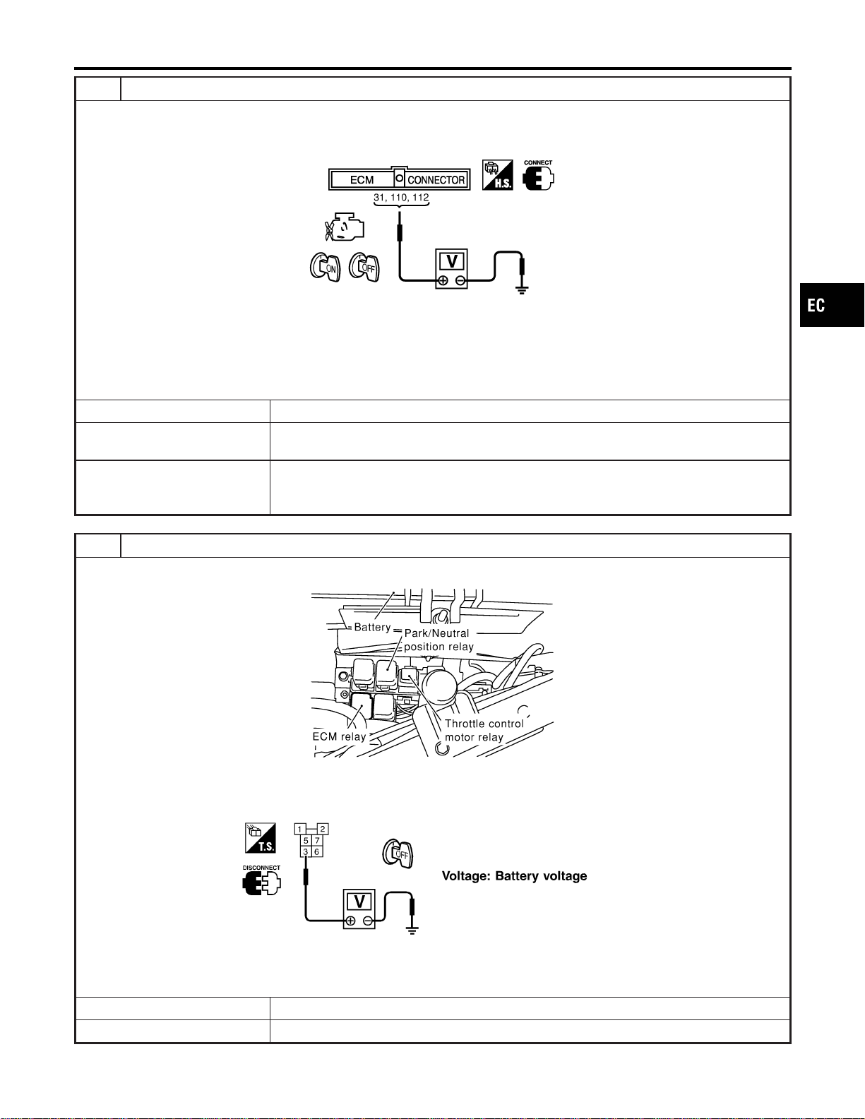
9 CHECK ECM POWER SUPPLY CIRCUIT-II
1. Turn ignition switch “ON” and then “OFF”.
2. Check voltage between ECM terminals 31, 110, 112 and ground with CONSULT-II or tester.
SEC899C
Voltage:
After turning ignition switch “OFF”, battery voltage will exist for a few seconds, then drop approximately
0V.
OK or NG
OK © GO TO 15.
NG (Battery voltage
does not exist.)
© GO TO 10.
NG (Battery voltage
exists for more than a
few seconds.)
© GO TO 12.
10 CHECK ECM POWER SUPPLY CIRCUIT-III
1. Disconnect ECM relay.
SEC044D
2. Check voltage between ECM relay terminal 3 and ground with CONSULT-II or tester.
SEF295X
OK or NG
OK © GO TO 12.
NG © GO TO 11.
GI
MA
EM
LC
FE
CL
MT
AT
AX
SU
BR
ST
RS
BT
HA
SC
EL
IDX
TROUBLE DIAGNOSIS FOR POWER SUPPLY
Main Power Supply and Ground Circuit (Cont’d)
EC-161
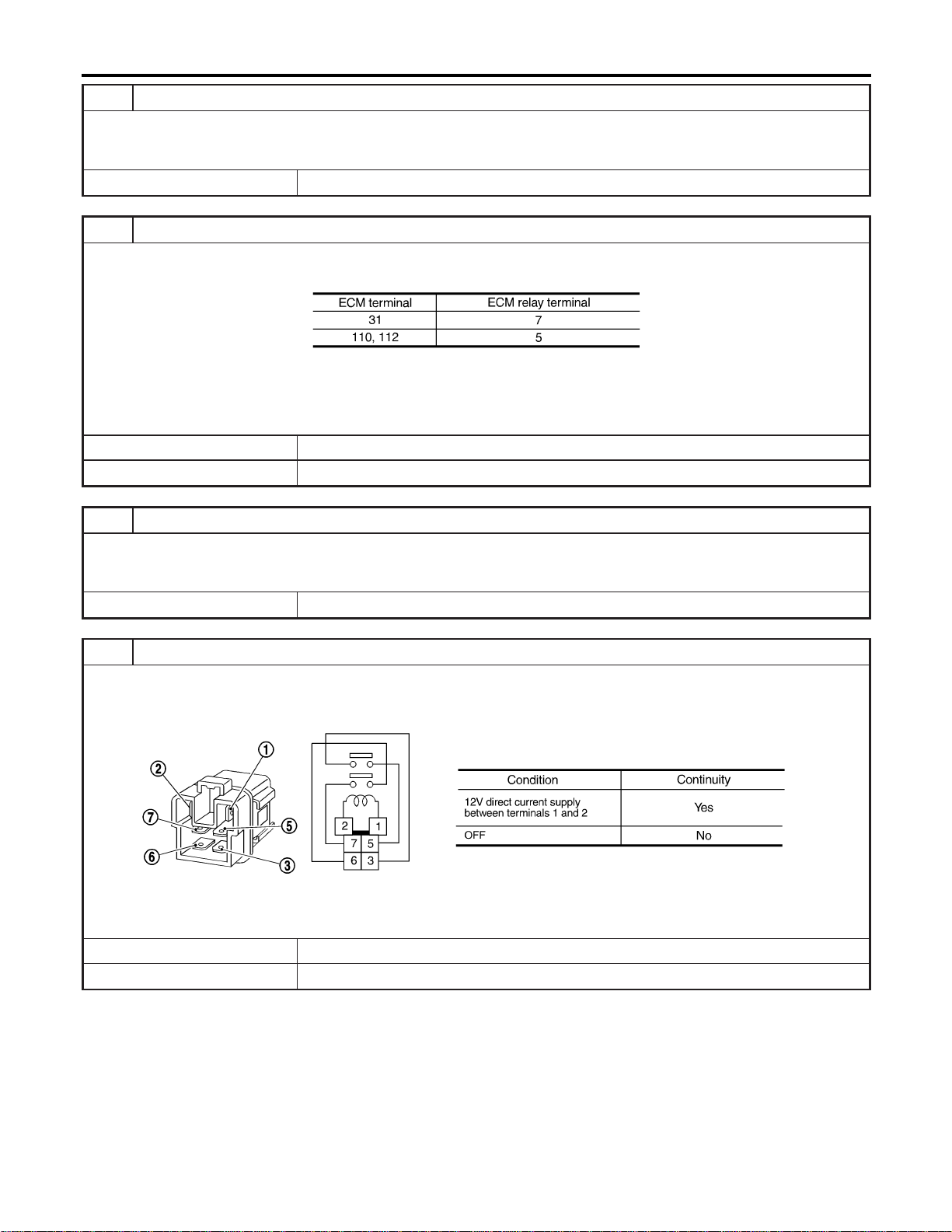
11 DETECT MALFUNCTIONING PART
Check the following.
I Joint connector-12
I Harness for open or short between ECM relay and 15A fuse
© Repair open circuit or short to ground or short to power in harness or connectors.
12 CHECK HARNESS CONTINUITY BETWEEN ECM RELAY AND ECM FOR OPEN AND SHORT
1. Check harness continuity between ECM terminals and ECM relay terminals as follows.
Refer to WIRING DIAGRAM.
MTBL1139
Continuity should exist.
2. Also check harness for short to ground and short to power.
OK or NG
OK © GO TO 14.
NG © GO TO 13.
13 DETECT MALFUNCTIONING PART
Check the following.
I Harness connectors E15, F18
I Harness for open or short between ECM and ECM relay
© Repair open circuit or short to ground or short to power in harness or connectors.
14 CHECK ECM RELAY
1. Apply 12V direct current between ECM relay terminals 1 and 2.
2. Check continuity between relay terminals 3 and 5, 6 and 7.
SEF296X
OK or NG
OK © GO TO 15.
NG © Replace ECM relay.
TROUBLE DIAGNOSIS FOR POWER SUPPLY
Main Power Supply and Ground Circuit (Cont’d)
EC-162
15 CHECK ECM GROUND CIRCUIT FOR OPEN AND SHORT-II
1. Turn ignition switch “OFF”.
2. Disconnect ECM harness connector.
3. Check harness continuity between ECM terminals 48, 57, 106, 108 and engine ground.
Refer to WIRING DIAGRAM.
Continuity should exist.
4. Also check harness for short to ground and short to power.
OK or NG
OK © GO TO 16.
NG © Repair open circuit or short to ground or short to power in harness or connectors.
16 CHECK INTERMITTENT INCIDENT
Refer to “TROUBLE DIAGNOSIS FOR INTERMITTENT INCIDENT”, EC-156.
© INSPECTION END
GI
MA
EM
LC
FE
CL
MT
AT
AX
SU
BR
ST
RS
BT
HA
SC
EL
IDX
TROUBLE DIAGNOSIS FOR POWER SUPPLY
Main Power Supply and Ground Circuit (Cont’d)
EC-163

Description
NFEC1245
CAN (Controller Area Network) is a serial communication line for
real time application. It is an on-vehicle multiplex communication
line with high data communication speed and excellent error detec-
tion ability. Many electonic control units are equipped onto a
vehicle, and each control unit shares information and links with
other control units during operation (not independent). In CAN
communication, control units are connected with 2 communication
lines (CAN H line, CAN L line) allowing a high rate of information
transmission with less wiring. Each control unit transmits/receives
data but selectively reads required data only.
On Board Diagnosis Logic
NFEC1246
DTC
No.
Trouble diagnosis name DTC detecting condition Possible cause
U1000
1000
U1001
1001
CAN communication line
I ECM cannot communicate to other control unit.
I ECM cannot communicate for more than the
specified time.
I Harness or connectors
(CAN communication line is open or
shorted.)
DTC Confirmation Procedure
NFEC1247
1. Turn ignition switch “ON” and wait at least 3 seconds.
2. Select “DATA MONITOR” mode with CONSULT-II.
3. If 1st trip DTC is detected, go to “Diagnostic Procedure”
EC-166.
DTC U1000, U1001 CAN COMMUNICATION LINE
Description
EC-164
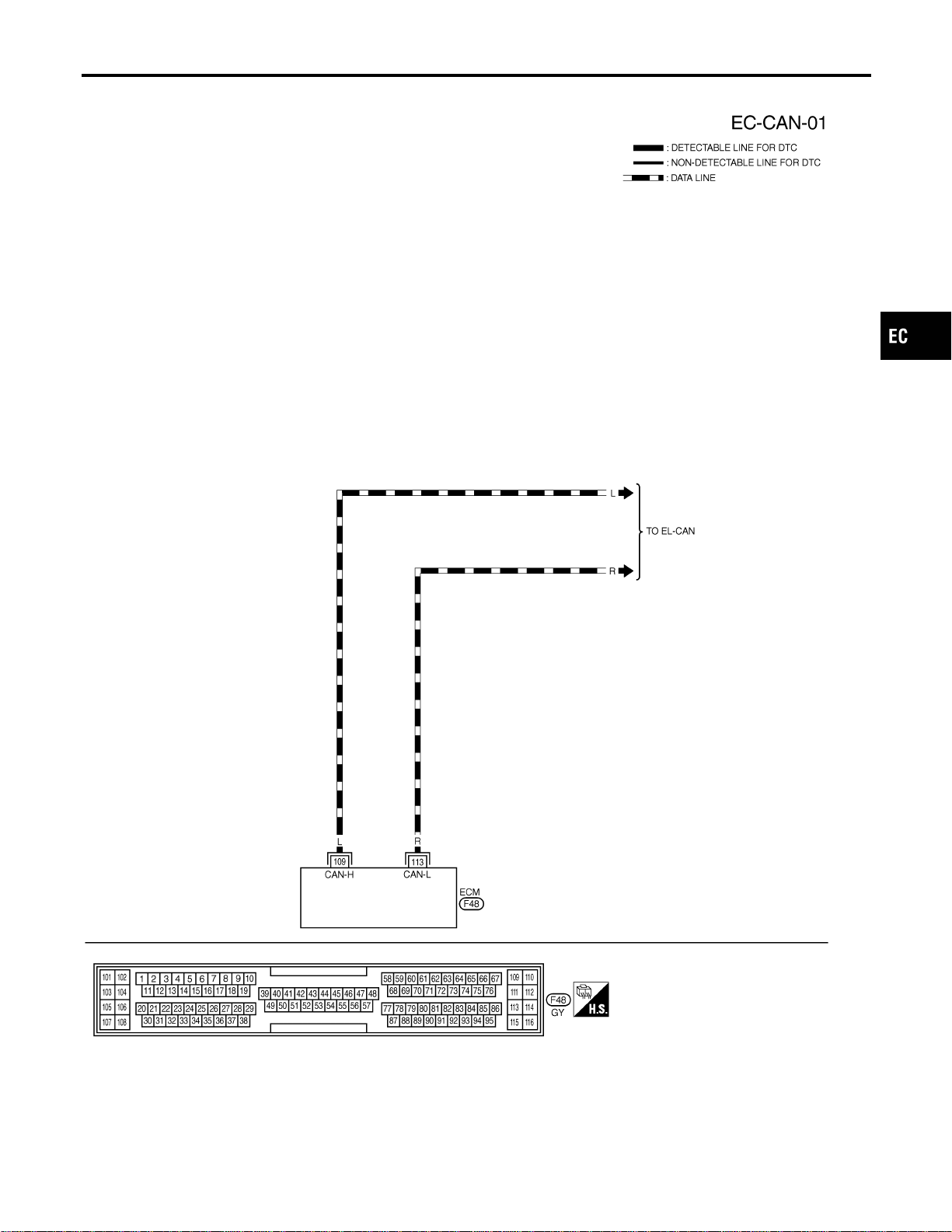
Wiring Diagram
NFEC1248
MEC923D
GI
MA
EM
LC
FE
CL
MT
AT
AX
SU
BR
ST
RS
BT
HA
SC
EL
IDX
DTC U1000, U1001 CAN COMMUNICATION LINE
Wiring Diagram
EC-165
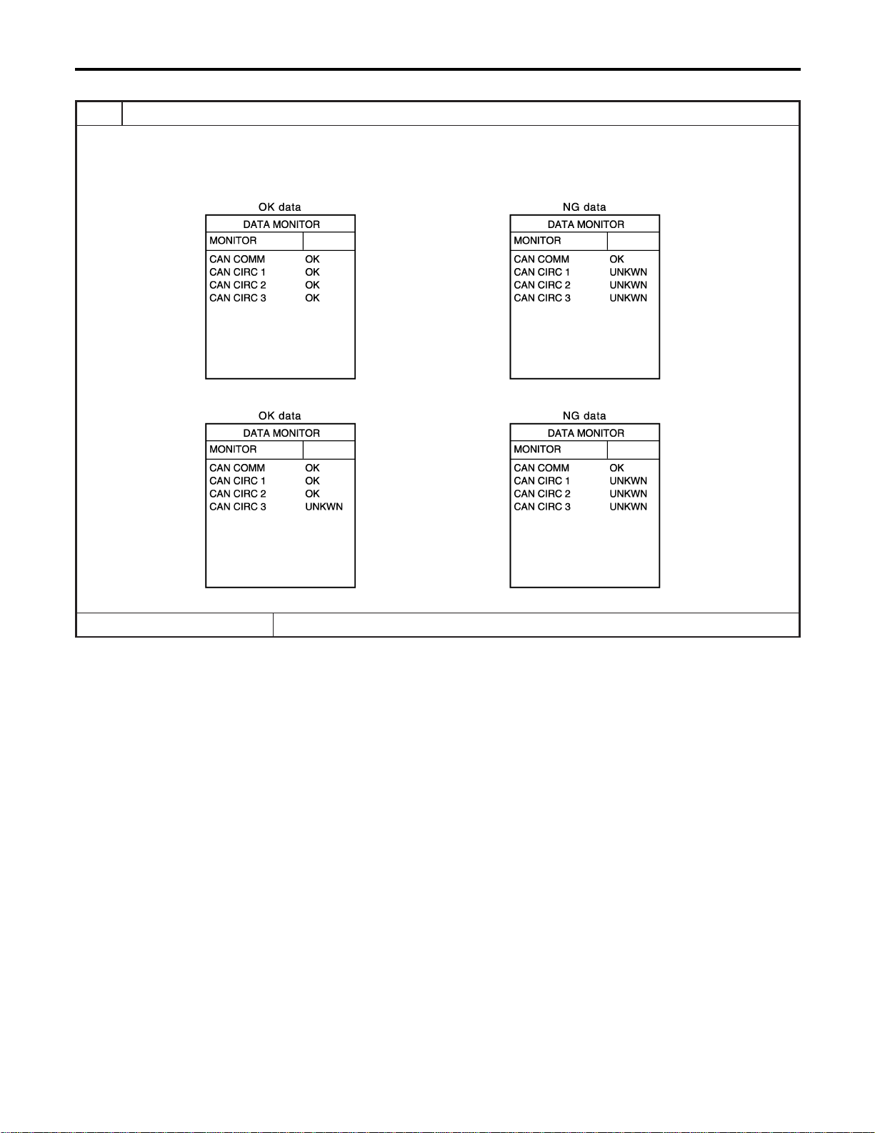
Diagnostic Procedure
NFEC1249
1 INSPECTION START
1. Turn ignition switch “ON”.
2. Select “CAN COMM SIGNALS” in “DATA MONITOR” mode with CONSULT-II.
3. Print out the CONSULT-II screen.
With TCS models
SEC898C
Without TCS models
SEC153D
© Go to EL-437 (With TCS models) or EL-430 (Without TCS models), “CAN SYSTEM”.
DTC U1000, U1001 CAN COMMUNICATION LINE
Diagnostic Procedure
EC-166
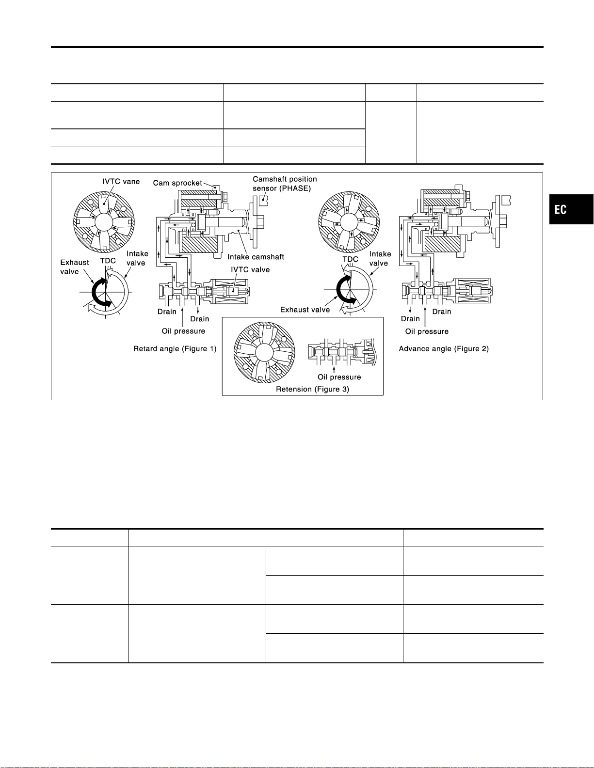
Description
NFEC0821
SYSTEM DESCRIPTION
NFEC0821S01
Sensor Input signal to ECM function ECM Actuator
Crankshaft position sensor (POS)
Camshaft position sensor (PHASE)
Engine speed
Intake valve
timing con-
trol
Intake valve timing control sole-
noid valveEngine coolant temperature sensor Engine coolant temperature
Vehicle speed sensor Vehicle speed
PBIB0606E
This mechanism hydraulically controls cam phases continuously with the fixed operating angle of the intake
valve.
The ECM receives signals such as crankshaft position, camshaft position, engine speed, and engine coolant
temperature. Then, the ECM sends ON/OFF pulse duty signals to the camshaft timing control valve depend-
ing on driving status. This makes it possible to control the shut/open timing of the intake valve to increase
engine torque in low/mid speed range and output in high-speed range.
CONSULT-II Reference Value in Data Monitor
Mode
NFEC0822
Specification data are reference values.
MONITOR ITEM CONDITION SPECIFICATION
INT/V TIM (B1)
INT/V TIM (B2)
I Engine: After warming up
I Shift lever “N”
I Quickly depressed accelerator
pedal
I No-load
Idle −5 - 5° CA
2,000 rpm Approximately 0 - 30° CA
INT/V SOL (B1)
INT/V SOL (B2)
I Engine: After warming up
I Shift lever “N”
I Quickly depressed accelerator
pedal
I No-load
Idle 0 - 2%
2,000 rpm Approximately 25 - 50%
GI
MA
EM
LC
FE
CL
MT
AT
AX
SU
BR
ST
RS
BT
HA
SC
EL
IDX
DTC P0011, P0021 IVT CONTROL
Description
EC-167
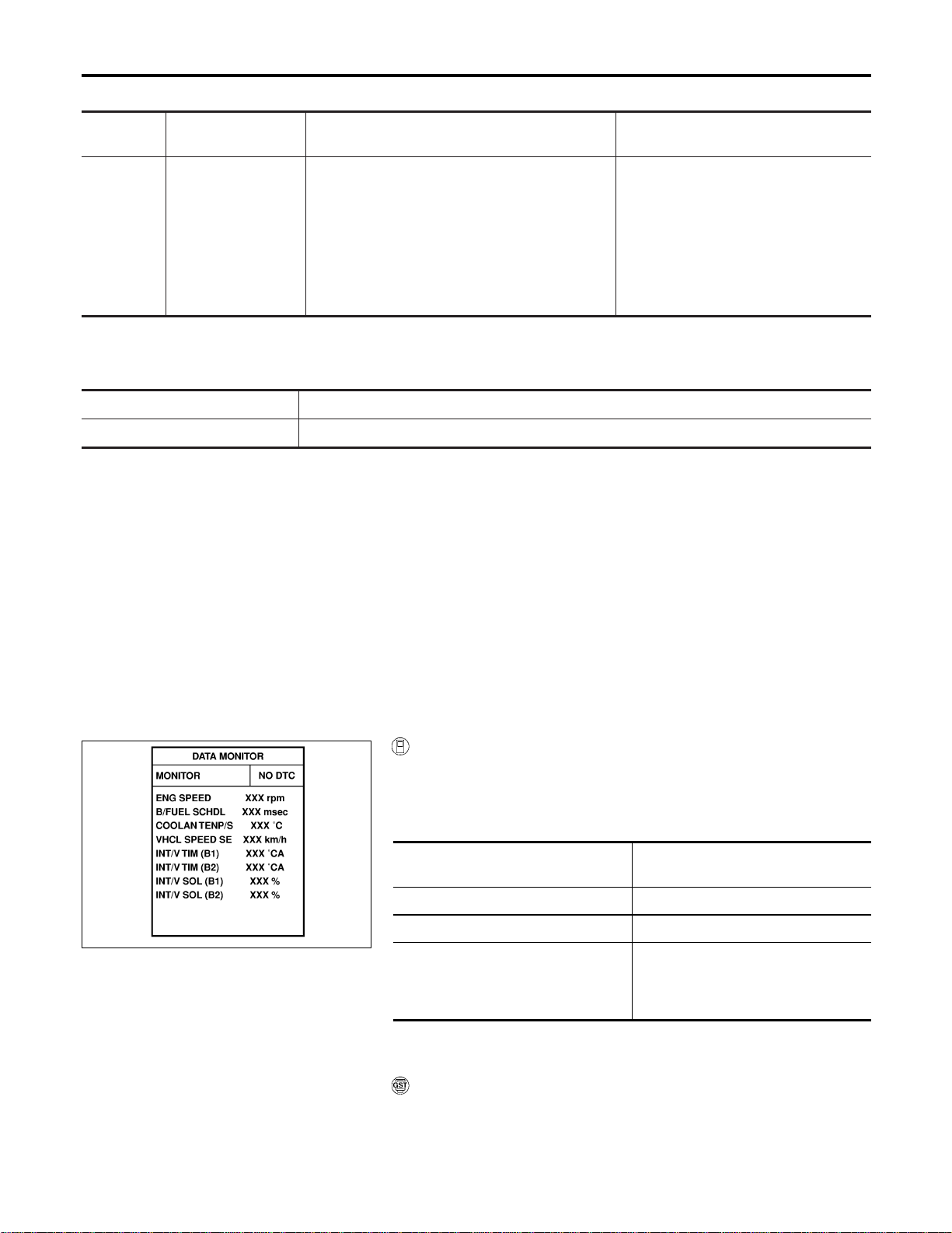
On Board Diagnosis Logic
NFEC0824
DTC No.
Trouble diagnosis
name
DTC Detecting Condition Possible Cause
P0011
0011
(Bank 1)
P0021
0021
(Bank 2)
Intake valve timing
control performance
There is a gap between angle of target and
phase-control angle degree.
I Harness or connectors
(Intake valve timing control solenoid
valve circuit is open or shorted.)
I Intake valve timing control solenoid
valve
I Crankshaft position sensor (POS)
I Camshaft position sensor (PHASE)
I Accumulation of debris to the signal
pick-up portion of the camshaft
FAIL-SAFE MODE
NFEC0824S01
When malfunction A or B is detected, the ECM enters fail-safe
mode and the MIL lights up.
Detected items Engine operating condition in fail-safe mode
Intake valve timing control The signal is not energized to the solenoid valve and the valve control does not function.
DTC Confirmation Procedure
NFEC0825
CAUTION:
Always drive at a safe speed.
NOTE:
I If “DTC Confirmation Procedure” has been previously
conducted, always turn ignition switch “OFF” and wait at
least 10 seconds before conducting the next test.
SEF353Z
WITH CONSULT-II
NFEC0825S03
1) Turn ignition switch “ON”.
2) Select “DATA MONITOR” mode with CONSULT-II.
3) Maintain the following conditions for at least 20 conecutive
seconds.
ENG SPEED
2,000 - 3,000 rpm (A constant rotation
is maintained.)
COOLANT TEMPS 70 - 90°C (158 - 194°F)
Selector lever 1st position (A/T or M/T)
Driving location
Driving vehicle uphill
(Increased engine load will help main-
tain the driving conditions required for
this test.)
4) If 1st trip DTC is detected, go to “Diagnostic Procedure”,
EC-172.
WITH GST
NFEC0825S04
Follow the procedure “WITH CONSULT-II” above.
DTC P0011, P0021 IVT CONTROL
On Board Diagnosis Logic
EC-168
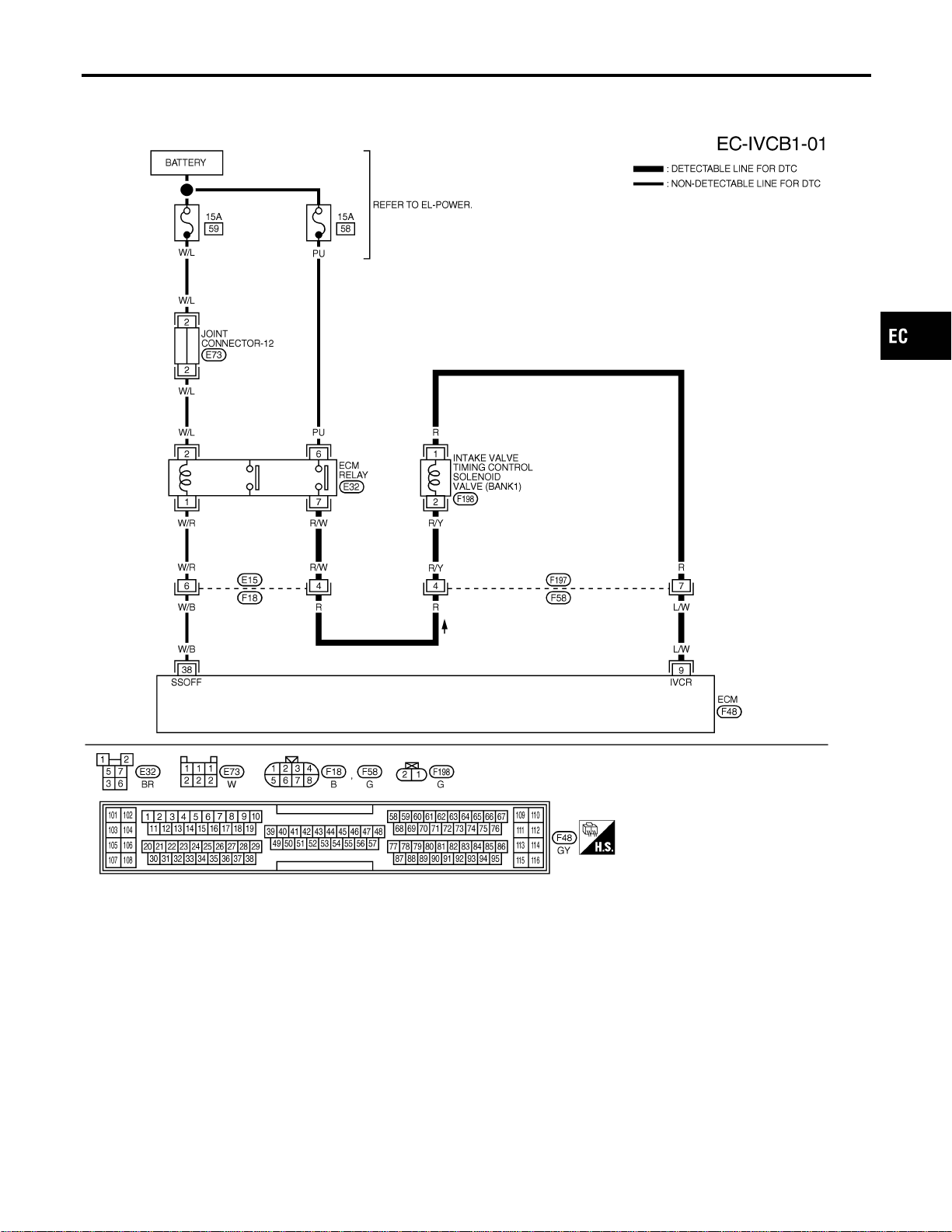
Wiring Diagram
=NFEC1409
BANK 1
MEC505D
GI
MA
EM
LC
FE
CL
MT
AT
AX
SU
BR
ST
RS
BT
HA
SC
EL
IDX
DTC P0011, P0021 IVT CONTROL
Wiring Diagram
EC-169
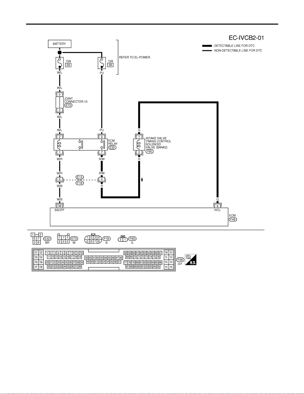
BANK 2
MEC504D
DTC P0011, P0021 IVT CONTROL
Wiring Diagram (Cont’d)
EC-170
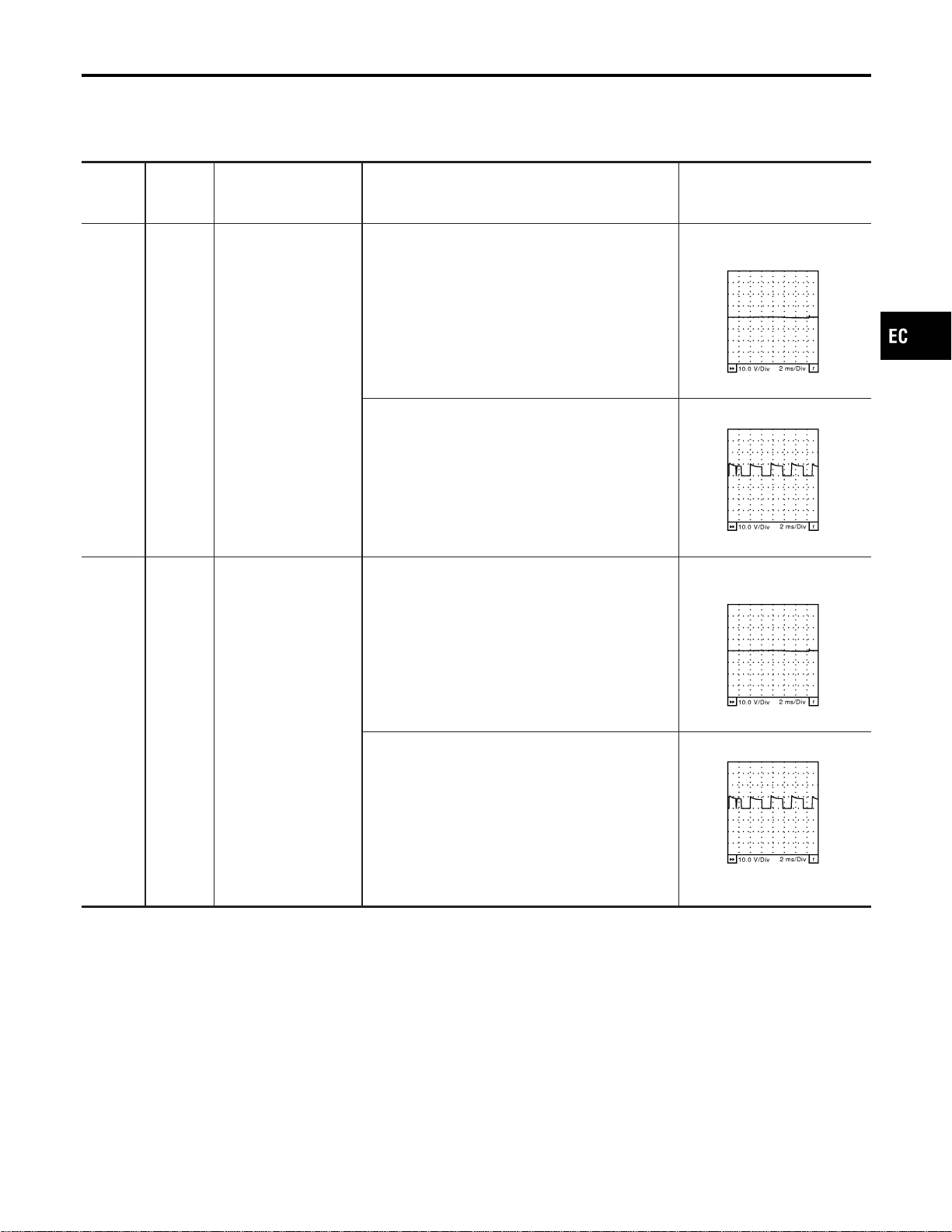
Specification data are reference values, and are measured between each terminal and ground.
CAUTION:
Do not use ECM ground terminals when measuring voltage. Doing so may result in damage to the
ECM’s transistor. Use a ground other than the ECM terminals, such as the ground.
TERMI-
NAL
NO.
WIRE
COLOR
ITEM CONDITION DATA (DC Voltage)
8G
Intake valve timing
control solenoid valves
(Bank 2)
[Engine is running]
I Warm-up condition
I Idle speed
Battery voltage
(11 - 14V)★
SEC988C
[Engine is running]
I Warm-up condition
I Engine speed is 2,500 rpm.
7 - 12V★
SEC989C
9 L/W
Intake valve timing
control solenoid valves
(Bank 1)
[Engine is running]
I Warm-up condition
I Idle speed
Battery voltage
(11 - 14V)★
SEC988C
[Engine is running]
I Warm-up condition
I Engine speed is 2,500 rpm.
7 - 12V★
SEC989C
★: Average voltage for pulse signal (Actual pulse signal can be confirmed by oscilloscope.)
GI
MA
EM
LC
FE
CL
MT
AT
AX
SU
BR
ST
RS
BT
HA
SC
EL
IDX
DTC P0011, P0021 IVT CONTROL
Wiring Diagram (Cont’d)
EC-171
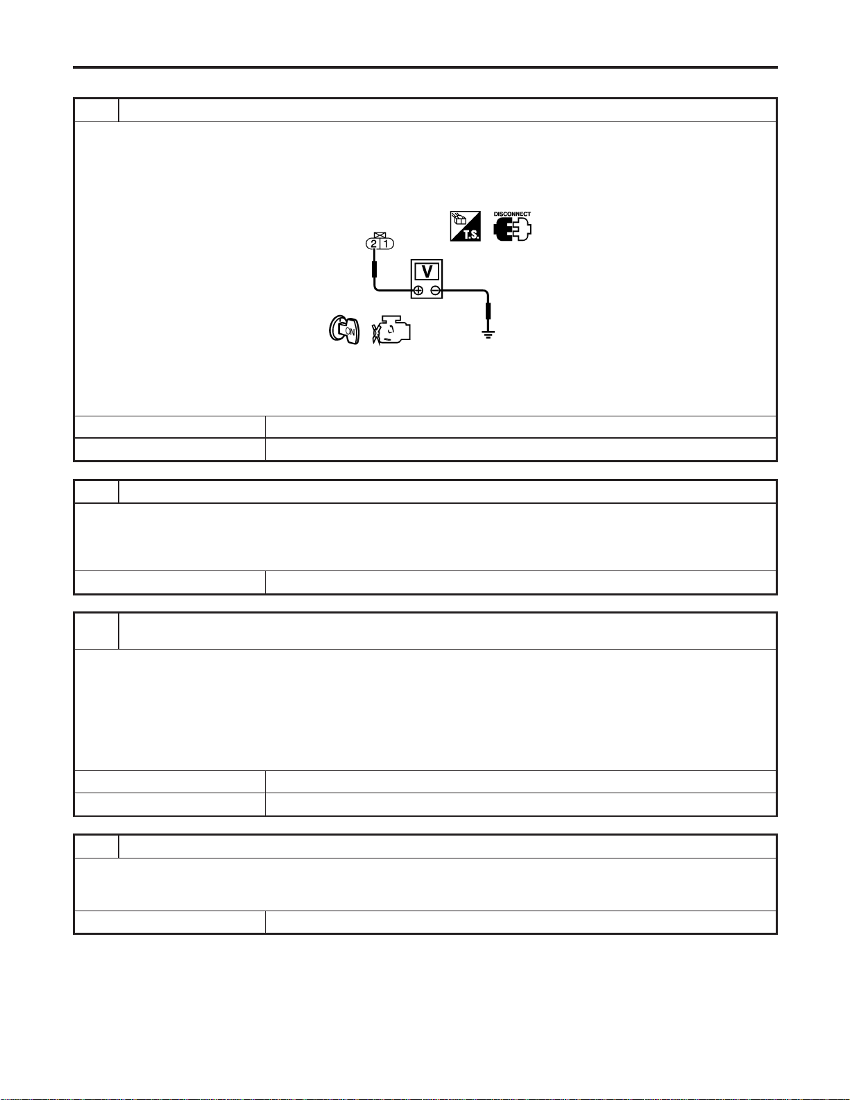
Diagnostic Procedure
NFEC1410
1 CHECK POWER SUPPLY CIRCUIT
1. Turn ignition switch “OFF”.
2. Disconnect intake valve timing control solenoid valve harness connector.
3. Turn ignition switch “ON”.
4. Check voltage between intake valve timing control solenoid valve terminal 2 and ground with CONSULT-II or tester.
PBIB0192E
Voltage: Battery voltage
OK or NG
OK © GO TO 3.
NG © GO TO 2.
2 DETECT MALFUNCTION PART
Check the following.
I Harness connectors E15, F18
I Harness connectors F58, F197
I Harness for open or short between intake valve timing control solenoid valve and ECM relay
© Repair harness or connectors.
3 CHECK INTAKE VALVE TIMING CONTROL SOLENOID VALVE OUTPUT SIGNAL CIRCUIT FOR OPEN
AND SHORT
1. Turn ignition switch “OFF”.
2. Disconnect ECM harness connector.
3. Check harness continuity between ECM terminal 9 (bank 1) or 8 (bank 2) and intake valve timing control solenoid valve
terminal 1. Refer to Wiring Diagram.
Continuity should exist.
4. Also check harness for short to ground and short to power.
OK or NG
OK © GO TO 5.
NG © GO TO 4.
4 DETECT MALFUNCTIONING PART
Check the following
I Harness connectors F58, F197
I Harness for open or short between intake valve timing control solenoid valve and ECM
© Repair open circuit or short to ground or short to power in harness or connectors.
DTC P0011, P0021 IVT CONTROL
Diagnostic Procedure
EC-172
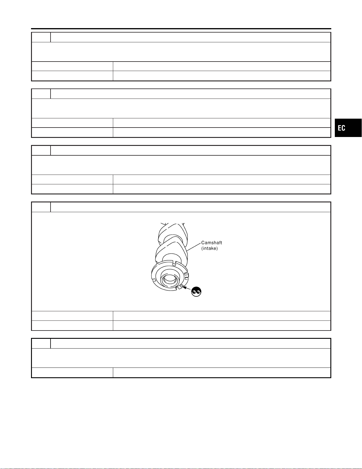
5 CHECK INTAKE VALVE TIMING CONTROL SOLENOID VALVE
Refer to “Component Inspection”, EC-174.
OK or NG
OK © GO TO 6.
NG © Replace intake valve timing control solenoid valve.
6 CHECK CRANKSHAFT POSITION SENSOR (POS)
Refer to “Component Inspection”, EC-336.
OK or NG
OK © GO TO 7.
NG © Replace crankshaft position sensor (POS).
7 CHECK CAMSHAFT POSITION SENSOR (PHASE)
Refer to “Component Inspection”, EC-345.
OK or NG
OK © GO TO 8.
NG © Replace.
8 CHECK CAMSHAFT (INTAKE)
Visually check for chipped signal plate at camshaft rear.
SEC905C
OK or NG
OK © GO TO 9.
NG © Replace camshaft.
9 CHECK INTERMITTENT INCIDENT
Refer to “TROUBLE DIAGNOSIS FOR INTERMITTENT INCIDENT”, EC-156.
OK or NG
© INSPECTION END
GI
MA
EM
LC
FE
CL
MT
AT
AX
SU
BR
ST
RS
BT
HA
SC
EL
IDX
DTC P0011, P0021 IVT CONTROL
Diagnostic Procedure (Cont’d)
EC-173

PBIB0193E
Component Inspection
NFEC1411
INTAKE VALVE TIMING CONTROL SOLENOID VALVE
1. Disconnect intake valve timing control solenoid valve harness
connector.
2. Check resistance between intake valve timing control solenoid
valve terminals as follows.
Terminals Resistance
1 and 2 7.0 - 7.5Ω at 20°C (68°F)
1 or 2 and ground
∞Ω
(Continuity should not exist)
DTC P0011, P0021 IVT CONTROL
Component Inspection
EC-174
Description
NFEC0826
SYSTEM DESCRIPTION
NFEC0826S01
Sensor Input Signal to ECM
ECM func-
tion
Actuator
Crankshaft position sensor (POS)
Engine speed
Heated
oxygen
sensor 1
heater con-
trol
Heated oxygen sensor 1 heat-
ers
Camshaft position sensor (PHASE)
The ECM performs ON/OFF control of the heated oxygen sensor 1 heaters corresponding to the engine speed.
OPERATION
NFEC0826S02
Engine speed rpm Heated oxygen sensor 1 heaters
Above 3,600 OFF
Below 3,600 ON
CONSULT-II Reference Value in Data Monitor
Mode
NFEC0827
Specification data are reference values.
MONITOR ITEM CONDITION SPECIFICATION
HO2S1 HTR (B1)
HO2S1 HTR (B2)
I Engine speed: Below 3,600 rpm ON
I Engine speed: Above 3,600 rpm OFF
On Board Diagnosis Logic
NFEC0829
DTC No.
Trouble diagnosis
name
DTC Detecting Condition Possible Cause
P0031
0031
(Bank 1)
P0051
0051
(Bank 2)
Heated oxygen sen-
sor 1 heater control
circuit low
The current amperage in the heated oxygen sen-
sor 1 heater circuit is out of the normal range.
(An excessively low voltage signal is sent to ECM
through the heated oxygen sensor 1 heater.)
I Harness or connectors
(The heated oxygen sensor 1 heater
circuit is open or shorted.)
I Heated oxygen sensor 1 heater
P0032
0032
(Bank 1)
P0052
0052
(Bank 2)
Heated oxygen sen-
sor 1 heater control
circuit high
The current amperage in the heated oxygen sen-
sor 1 heater circuit is out of the normal range.
(An excessively high voltage signal is sent to ECM
through the heated oxygen sensor 1 heater.)
I Harness or connectors
(The heated oxygen sensor 1 heater
circuit is shorted.)
I Heated oxygen sensor 1 heater
GI
MA
EM
LC
FE
CL
MT
AT
AX
SU
BR
ST
RS
BT
HA
SC
EL
IDX
DTC P0031, P0032, P0051, P0052 HO2S1 HEATER
Description
EC-175
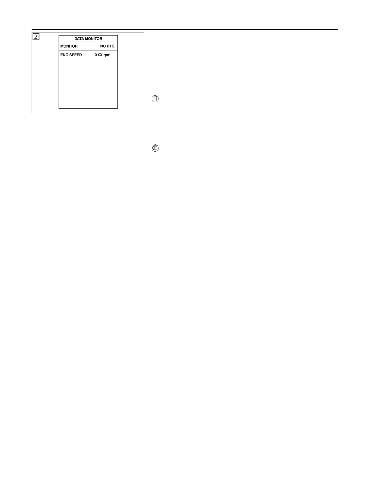
SEF058Y
DTC Confirmation Procedure
NFEC0830
NOTE:
If “DTC Confirmation Procedure” has been previously conducted,
always turn ignition switch “OFF” and wait at least 10 seconds
before conducting the next test.
TESTING CONDITION:
Before performing the following procedure, confirm that bat-
tery voltage is between 10.5V and 16V at idle.
WITH CONSULT-II
NFEC0830S01
1) Turn ignition switch “ON” and select “DATA MONITOR” mode
with CONSULT-II.
2) Start engine and run it for at least 6 seconds at idle speed.
3) If 1st trip DTC is detected, go to “Diagnostic Procedure”,
EC-179.
WITH GST
NFEC0830S02
1) Start engine and run it for at least 6 seconds at idle speed.
2) Turn ignition switch “OFF” and wait at least 10 seconds.
3) Start engine and run it for at least 6 seconds at idle speed.
4) Select “MODE 3” with GST.
5) If DTC is detected, go to “Diagnostic Procedure”, EC-179.
I When using GST, “DTC Confirmation Procedure” should
be performed twice as much as when using CONSULT-II
because GST cannot display MODE 7 (1st trip DTC) con-
cerning this diagnosis. Therefore, using CONSULT-II is
recommended.
DTC P0031, P0032, P0051, P0052 HO2S1 HEATER
DTC Confirmation Procedure
EC-176
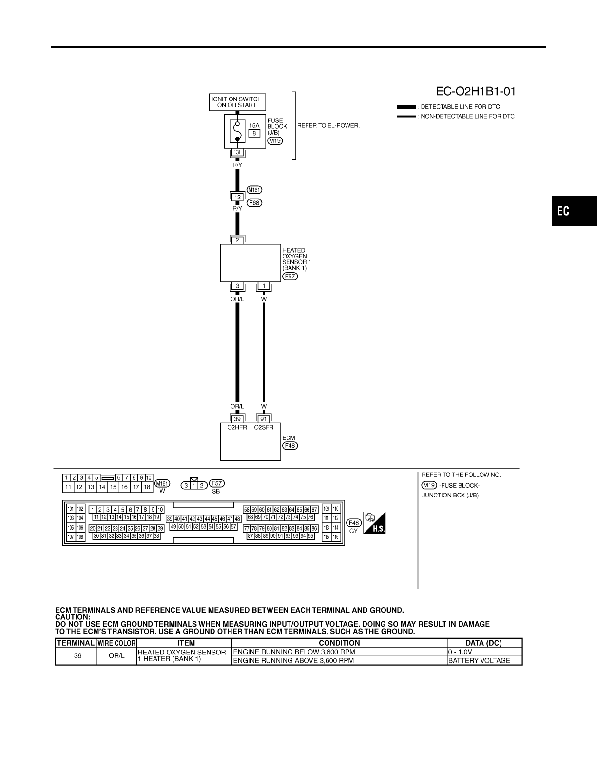
Wiring Diagram
NFEC0831
BANK 1
NFEC0831S01
MEC481D
SEC095D
GI
MA
EM
LC
FE
CL
MT
AT
AX
SU
BR
ST
RS
BT
HA
SC
EL
IDX
DTC P0031, P0032, P0051, P0052 HO2S1 HEATER
Wiring Diagram
EC-177
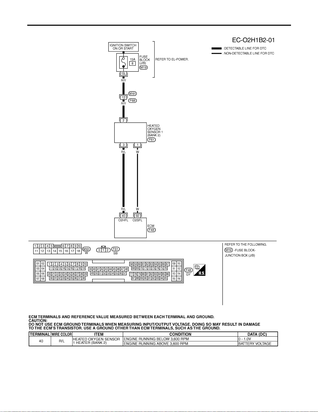
BANK 2
NFEC0831S02
MEC482D
SEC096D
DTC P0031, P0032, P0051, P0052 HO2S1 HEATER
Wiring Diagram (Cont’d)
EC-178
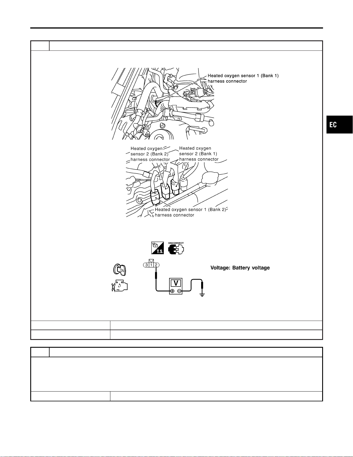
Diagnostic Procedure
NFEC0832
1 CHECK HO2S1 POWER SUPPLY CIRCUIT
1. Turn ignition switch “OFF”.
2. Disconnect corresponding heated oxygen sensor 1 harness connector.
SEC099D
SEC134D
3. Turn ignition switch “ON”.
4. Check voltage between HO2S1 terminal 2 and ground with CONSULT-II or tester.
SEF311X
OK or NG
OK © GO TO 3.
NG © GO TO 2.
2 DETECT MALFUNCTIONING PART
Check the following.
I Harness connectors M161, F68
I Fuse block (J/B) connector M19
I 15A fuse
I Harness for open or short between heated oxygen sensor 1 and fuse
© Repair harness or connectors.
GI
MA
EM
LC
FE
CL
MT
AT
AX
SU
BR
ST
RS
BT
HA
SC
EL
IDX
DTC P0031, P0032, P0051, P0052 HO2S1 HEATER
Diagnostic Procedure
EC-179
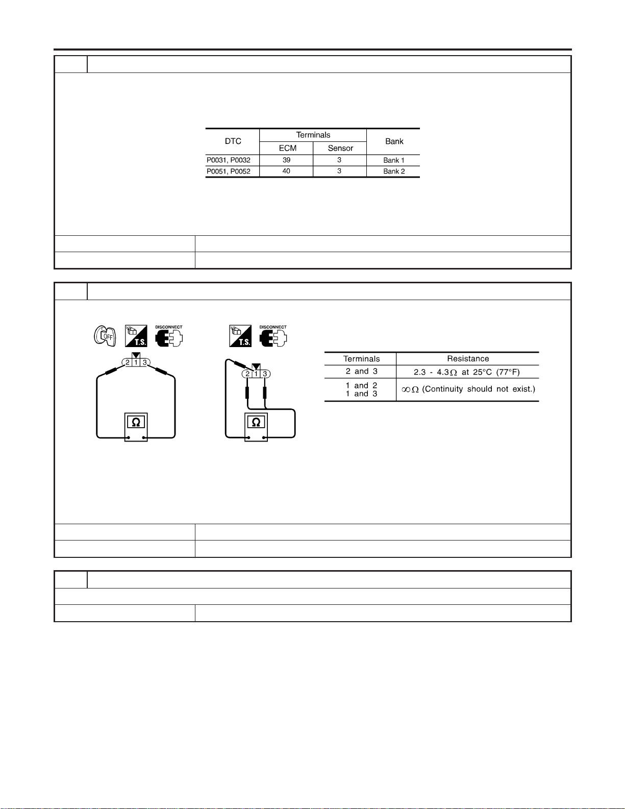
3 CHECK HO2S1 OUTPUT SIGNAL CIRCUIT FOR OPEN AND SHORT
1. Turn ignition switch “OFF”.
2. Disconnect ECM harness connector.
3. Check harness continuity between ECM terminal and HO2S1 terminal as follows.
Refer to Wiring Diagram.
MTBL1140
Continuity should exist.
4. Also check harness for short to ground and short to power.
OK or NG
OK © GO TO 4.
NG © Repair open circuit or short to ground or short to power in harness or connectors.
4 CHECK HEATED OXYGEN SENSOR 1 HEATER
Check resistance between HO2S1 terminals as follows.
SEF310X
CAUTION:
I Discard any heated oxygen sensor which has been dropped from a height of more than 0.5 m (19.7 in) onto a
hard surface such as a concrete floor; use a new one.
I Before installing new oxygen sensor, clean exhaust system threads using Oxygen Sensor Thread Cleaner tool
J-43897-18 or J-43897-12 and approved anti-seize lubricant.
OK or NG
OK © GO TO 5.
NG © Replace malfunctioning heated oxygen sensor.
5 CHECK INTERMITTENT INCIDENT
Refer to “TROUBLE DIAGNOSIS FOR INTERMITTENT INCIDENT”, EC-156.
© INSPECTION END
DTC P0031, P0032, P0051, P0052 HO2S1 HEATER
Diagnostic Procedure (Cont’d)
EC-180
Description
NFEC0833
SYSTEM DESCRIPTION
NFEC0833S01
Sensor Input Signal to ECM
ECM func-
tion
Actuator
Crankshaft position sensor (POS)
Engine speed
Heated
oxygen
sensor
heater 2
control
Heated oxygen sensor 2 heat-
ers
Camshaft position sensor (PHASE)
The ECM performs ON/OFF control of the heated oxygen sensor 2 heaters corresponding to the engine speed.
OPERATION
NFEC0833S02
Engine speed rpm Heated oxygen sensor 2 heaters
Above 3,600 OFF
Below 3,600 ON
CONSULT-II Reference Value in Data Monitor
Mode
NFEC0834
Specification data are reference values.
MONITOR ITEM CONDITION SPECIFICATION
HO2S2 HTR (B1)
HO2S2 HTR (B2)
I Engine is running above 3,600 rpm. OFF
I Engine is running below 3,600 rpm after driving for 2 minutes at a
speed of 70 km/h (43 MPH) or more.
ON
On Board Diagnosis Logic
NFEC0836
DTC No.
Trouble diagnosis
name
DTC Detecting Condition Possible Cause
P0037
0037
(Bank 1)
P0057
0057
(Bank 2)
Heated oxygen sen-
sor 2 heater control
circuit low
The current amperage in the heated oxygen sen-
sor 2 heater circuit is out of the normal range.
(An excessively low voltage signal is sent to ECM
through the heated oxygen sensor 2 heater.)
I Harness or connectors
(The heated oxygen sensor 2 heater
circuit is open or shorted.)
I Heated oxygen sensor 2 heater
P0038
0038
(Bank 1)
P0058
0058
(Bank 2)
Heated oxygen sen-
sor 2 heater control
circuit high
The current amperage in the heated oxygen sen-
sor 2 heater circuit is out of the normal range.
(An excessively high voltage signal is sent to ECM
through the heated oxygen sensor 2 heater.)
I Harness or connectors
(The heated oxygen sensor 2 heater
circuit is shorted.)
I Heated oxygen sensor 2 heater
GI
MA
EM
LC
FE
CL
MT
AT
AX
SU
BR
ST
RS
BT
HA
SC
EL
IDX
DTC P0037, P0038, P0057, P0058 HO2S2 HEATER
Description
EC-181
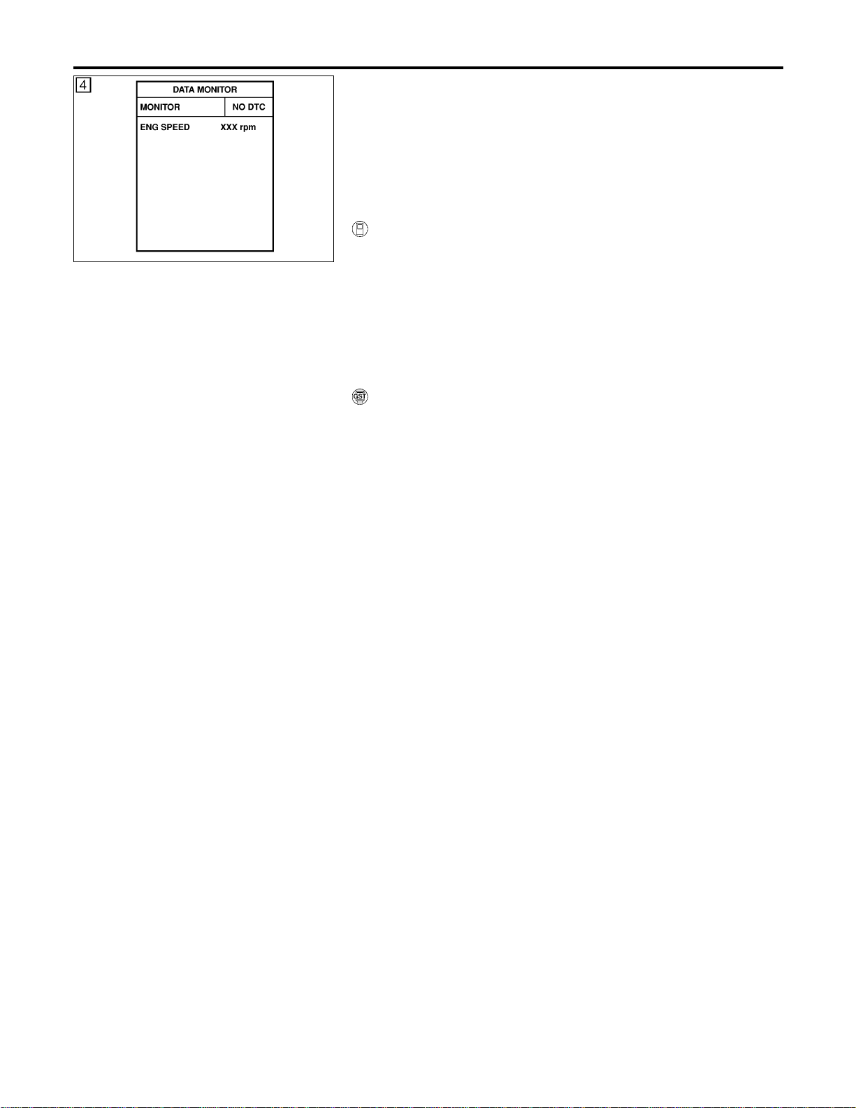
SEF058Y
DTC Confirmation Procedure
NFEC0837
NOTE:
If “DTC Confirmation Procedure” has been previously conducted,
always turn ignition switch “OFF” and wait at least 10 seconds
before conducting the next test.
TESTING CONDITION:
Before performing the following procedure, confirm that bat-
tery voltage is between 11.0V and 16V at idle.
WITH CONSULT-II
NFEC0837S01
1) Turn ignition switch “ON” and select “DATA MONITOR” mode
with CONSULT-II.
2) Start engine.
3) Drive vehicle at a speed of more than 70 km/h (43 MPH) for 2
consecutive minutes.
4) Stop vehicle and let engine idle for at least 6 seconds.
5) If 1st trip DTC is detected, go to “Diagnostic Procedure”,
EC-185.
WITH GST
NFEC0837S02
1) Start engine.
2) Drive vehicle at a speed of more than 70 km/h (43 MPH) for 2
consecutive minutes.
3) Stop vehicle and let engine idle for at least 6 seconds.
4) Turn ignition switch “OFF” and wait at least 10 seconds.
5) Start engine.
6) Drive vehicle at a speed of more than 70 km/h (43 MPH) for 2
consecutive minutes.
7) Stop vehicle and let engine idle for at least 6 seconds.
8) Select “MODE 3” with GST.
9) If DTC is detected, go to “Diagnostic Procedure”, EC-185.
I When using GST, “DTC Confirmation Procedure” should
be performed twice as much as when using CONSULT-II
because GST cannot display MODE 7 (1st trip DTC) con-
cerning this diagnosis. Therefore, using CONSULT-II is
recommended.
DTC P0037, P0038, P0057, P0058 HO2S2 HEATER
DTC Confirmation Procedure
EC-182
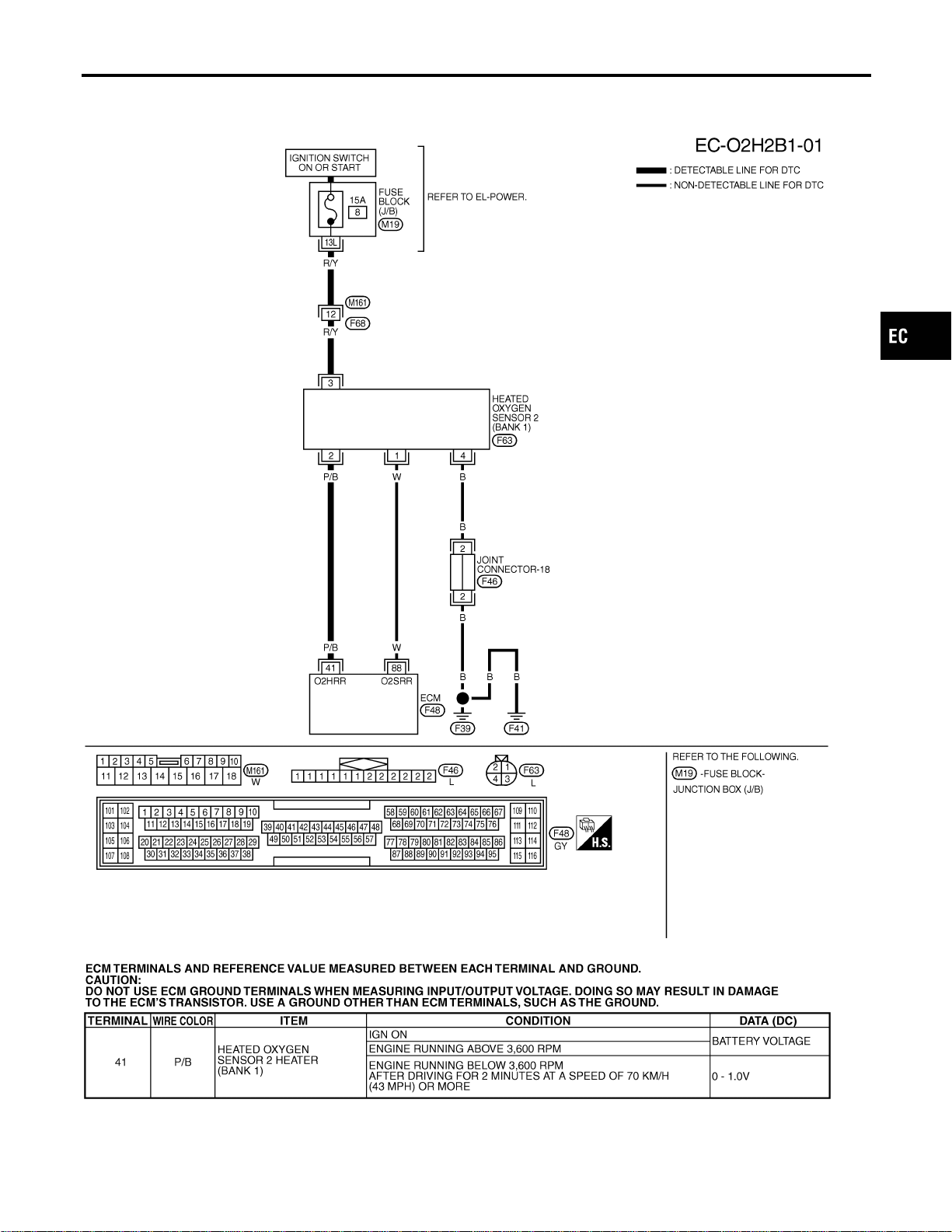
Wiring Diagram
=NFEC0838
BANK 1
NFEC0838S01
MEC485D
SEC100D
GI
MA
EM
LC
FE
CL
MT
AT
AX
SU
BR
ST
RS
BT
HA
SC
EL
IDX
DTC P0037, P0038, P0057, P0058 HO2S2 HEATER
Wiring Diagram
EC-183
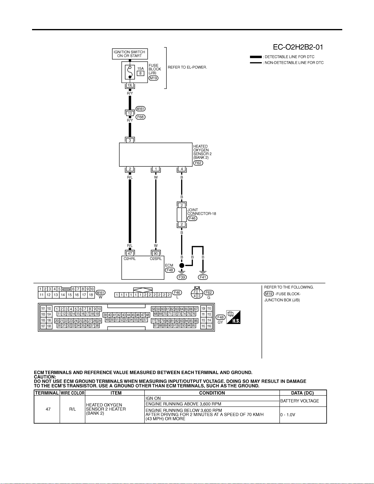
BANK 2
NFEC0838S02
MEC486D
SEC101D
DTC P0037, P0038, P0057, P0058 HO2S2 HEATER
Wiring Diagram (Cont’d)
EC-184
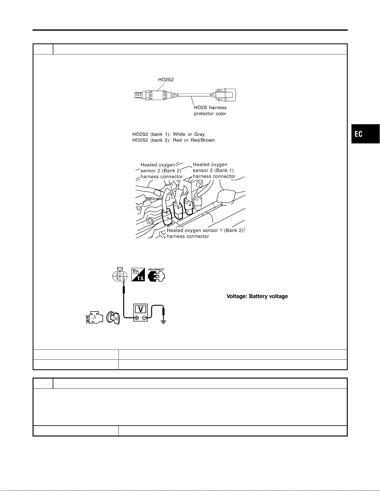
Diagnostic Procedure
NFEC0839
1 CHECK HO2S2 POWER SUPPLY CIRCUIT
1. Turn ignition switch “OFF”.
2. Check heated oxygen sensor harness 2 protector color.
SEF372ZB
3. Disconnect corresponding heated oxygen sensor 2 harness connector.
SEC134D
4. Turn ignition switch “ON”.
5. Check voltage between HO2S2 terminal 3 and ground.
SEF314X
OK or NG
OK © GO TO 3.
NG © GO TO 2.
2 DETECT MALFUNCTIONING PART
Check the following.
I Harness connectors M161, F68
I Fuse block (J/B) connector M19
I 15A fuse
I Harness for open or short between heated oxygen sensor 2 and fuse
© Repair harness or connectors.
GI
MA
EM
LC
FE
CL
MT
AT
AX
SU
BR
ST
RS
BT
HA
SC
EL
IDX
DTC P0037, P0038, P0057, P0058 HO2S2 HEATER
Diagnostic Procedure
EC-185
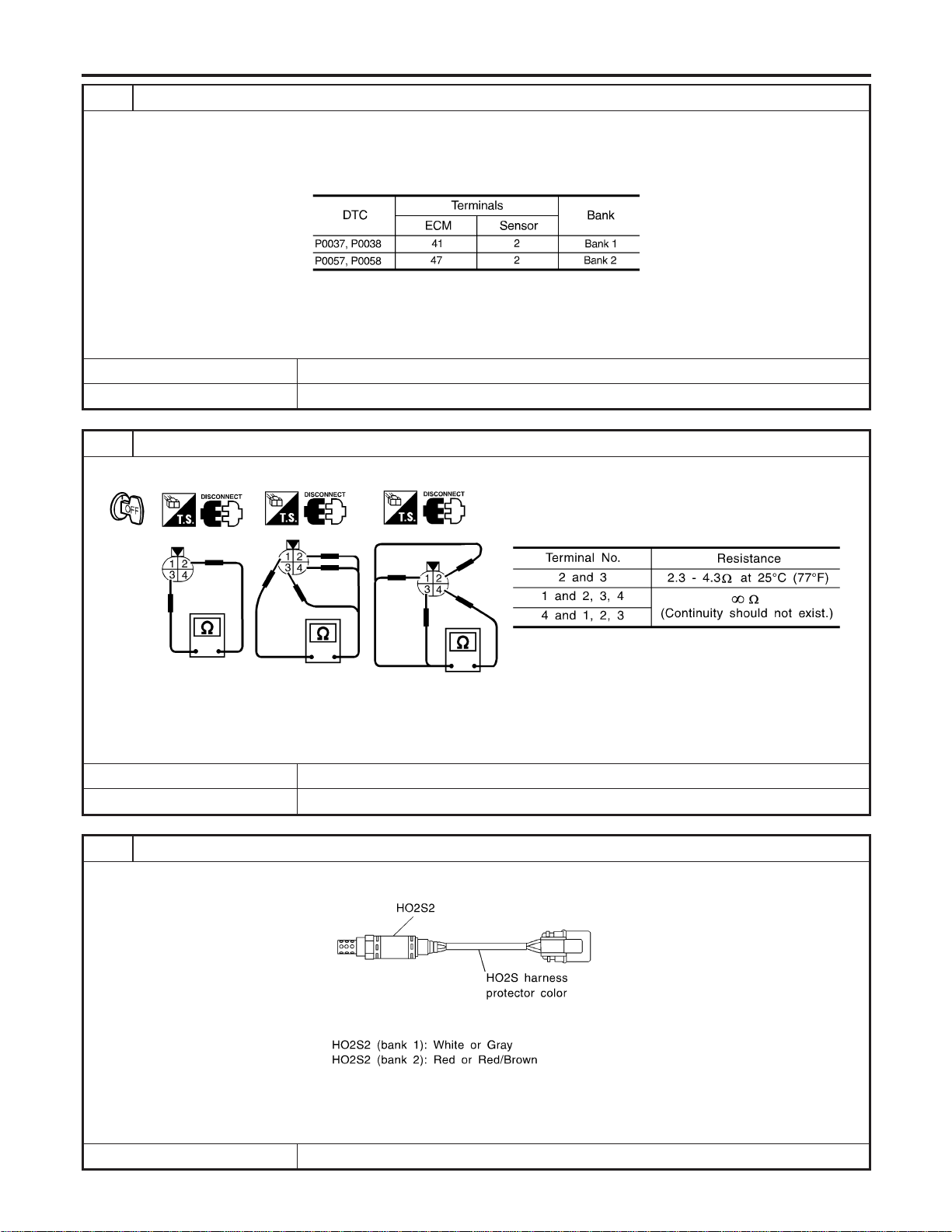
3 CHECK HO2S2 OUTPUT SIGNAL CIRCUIT FOR OPEN AND SHORT
1. Turn ignition switch “OFF”.
2. Disconnect ECM harness connector.
3. Check harness continuity between ECM terminal and HO2S2 terminal as follows.
Refer to Wiring Diagram.
MTBL1141
Continuity should exist.
4. Also check harness for short to ground and short to power.
OK or NG
OK © GO TO 4.
NG © Repair open circuit or short to ground or short to power in harness or connectors.
4 CHECK HEATED OXYGEN SENSOR 2 HEATER
Check the resistance between HO2S2 terminals as follows.
SEF315X
CAUTION:
Discard any heated oxygen sensor which has been dropped from a height of more than 0.5 m (19.7 in) onto a
hard surface such as a concrete floor; use a new one.
OK or NG
OK © GO TO 6.
NG © GO TO 5.
5 REPLACE HEATED OXYGEN SENSOR 2
Check rear heated oxygen sensor harness protector color.
SEF372ZB
CAUTION:
Before installing new oxygen sensor, clean exhaust system threads using Oxygen Sensor Thread Cleaner tool
J-43897-18 or J-43897-12 and approved anti-seize lubricant.
© Replace malfunctioning heated oxygen sensor 2.
DTC P0037, P0038, P0057, P0058 HO2S2 HEATER
Diagnostic Procedure (Cont’d)
EC-186
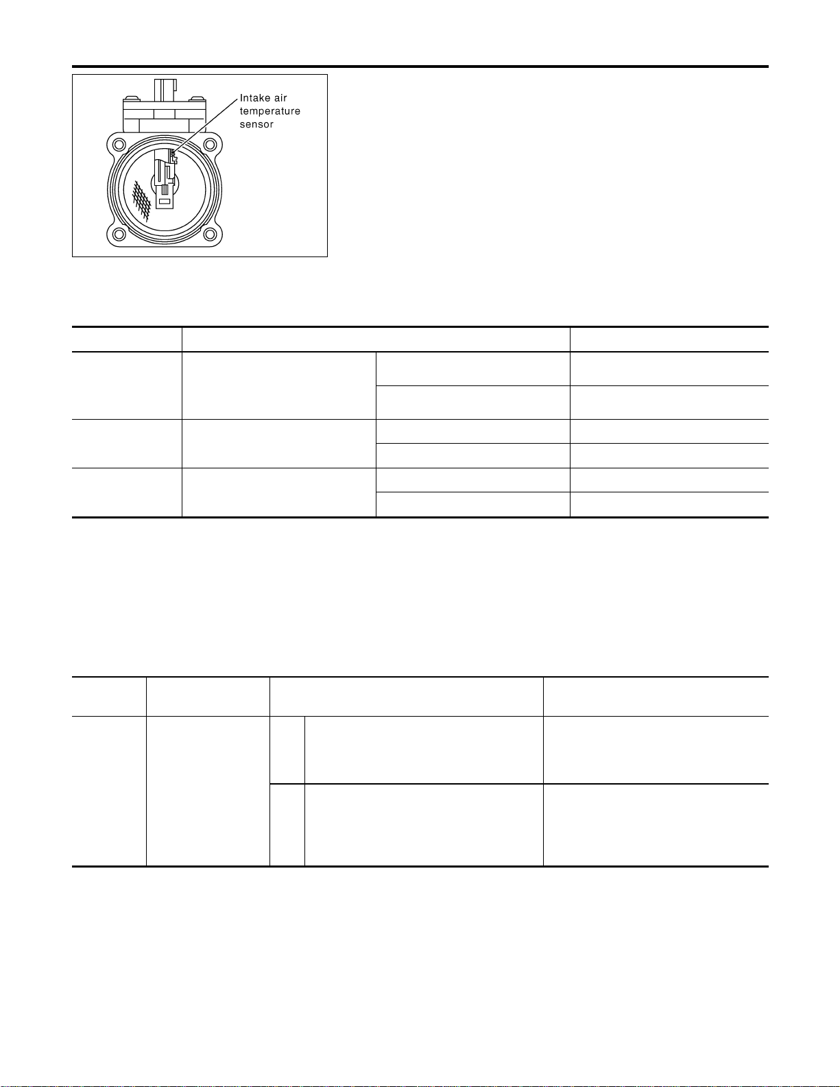
SEC266C
Component Description
NFEC0840
The mass air flow sensor is placed in the stream of intake air. It
measures the intake flow rate by measuring a part of the entire
intake flow. It consists of a hot film that is supplied with electric
current from the ECM. The temperature of the hot film is controlled
by the ECM a certain amount. The heat generated by the hot film
is reduced as the intake air flows around it. The more air, the
greater the heat loss.
Therefore, the ECM must supply more electric current to maintain
the temperature of the hot film as air flow increases. The ECM
detects the air flow by means of this current change.
CONSULT-II Reference Value in Data Monitor
Mode
NFEC0841
Specification data are reference values.
MONITOR ITEM CONDITION SPECIFICATION
MAS A/F SE-B1
I Engine: After warming up
I Air conditioner switch: “OFF”
I Shift lever: “N”
I No-load
Idle 1.1 - 1.5V
2,500 rpm 1.7 - 2.4V
CAL/LD VALUE ditto
Idle 10 - 35%
2,500 rpm 10 - 35%
MASS AIRFLOW ditto
Idle 2.0 - 6.0 g·m/s
2,500 rpm 7.0 - 20.0 g·m/s
On Board Diagnosis Logic
NFEC1428
DTC No.
Trouble diagnosis
name
DTC Detecting Condition Possible Cause
P0101
0101
Mass air flow sensor
circuit range/
performance problem
A) A high voltage from the sensor is sent to
ECM under light load driving condition.
I Harness or connectors
(The sensor circuit is open or
shorted.)
I Mass air flow sensor
B) A low voltage from the sensor is sent to
ECM under heavy load driving condition.
I Harness or connectors
(The sensor circuit is open or
shorted.)
I Intake air leaks
I Mass air flow sensor
DTC P0101 MAF SENSOR
Component Description
EC-188
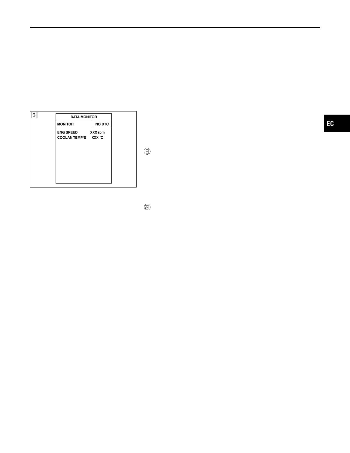
DTC Confirmation Procedure
NFEC0844
NOTE:
If “DTC Confirmation Procedure” has been previously conducted,
always turn ignition switch “OFF” and wait at least 10 seconds
before conducting the next test.
SEF174Y
PROCEDURE FOR MALFUNCTION A
NFEC0844S01
NOTE:
If engine will not start or stops soon, wait at least 10 seconds with
engine stopped (Ignition switch “ON”) instead of running engine at
idle speed.
With CONSULT-II
NFEC0844S0101
1) Turn ignition switch “ON”.
2) Select “DATA MONITOR” mode with CONSULT-II.
3) Start engine and warm it up to normal operating temperature.
4) Run engine for at least 10 seconds at idle speed.
5) If 1st trip DTC is detected, go to “Diagnostic Procedure”,
EC-192.
With GST
NFEC0844S0102
Follow the procedure “With CONSULT-II” above.
GI
MA
EM
LC
FE
CL
MT
AT
AX
SU
BR
ST
RS
BT
HA
SC
EL
IDX
DTC P0101 MAF SENSOR
DTC Confirmation Procedure
EC-189
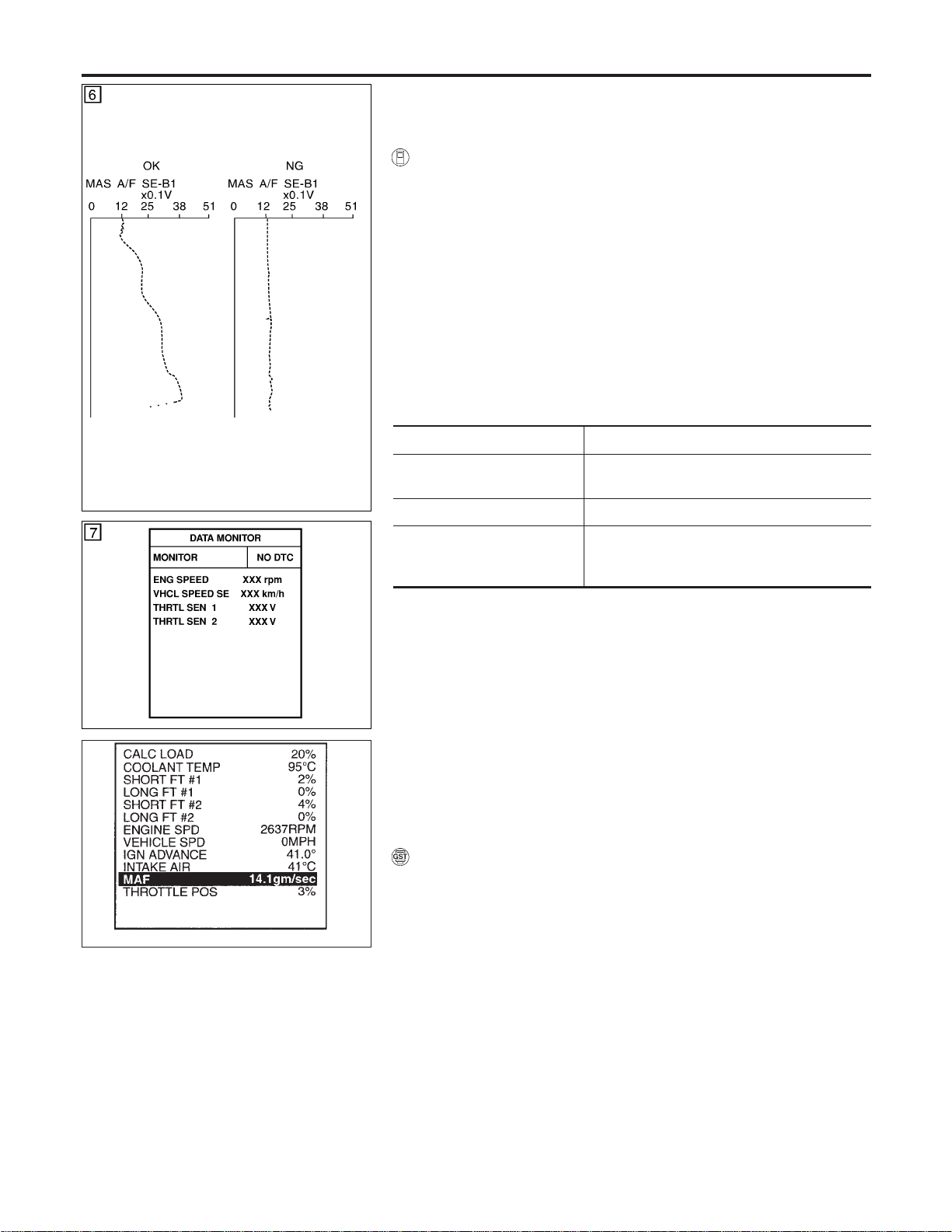
SEF243Y
PBIB0199E
PROCEDURE FOR MALFUNCTION B
NFEC0844S02
CAUTION:
Always drive vehicle at a safe speed.
With CONSULT-II
NFEC0844S0201
1) Turn ignition switch “ON”.
2) Start engine and warm it up to normal operating temperature.
If engine cannot be started, go to “Diagnostic Procedure”,
EC-192.
3) Select “DATA MONITOR” mode with CONSULT-II.
4) Check the voltage of MAS A/F SE B1 with “DATA MONITOR”.
5) Increases engine speed to about 4,000 rpm.
6) Monitor the linear voltage rise in response to engine speed
increases.
If NG, go to “Diagnostic Procedure”, EC-192.
If OK, go to following step.
7) Maintain the following conditions for at least 10 consecutive
seconds.
ENG SPEED More than 2,000 rpm
THRTL SEN 1
THRTL SEN 2
More than 3V
Selector lever Suitable position
Driving location Driving vehicle uphill (Increased engine load)
will help maintain the driving conditions
required for this test.
8) If 1st trip DTC is detected, go to “Diagnostic Procedure”,
EC-192.
SEF534P
Overall Function Check
NFEC0845
PROCEDURE FOR MALFUNCTION B
NFEC0845S01
Use this procedure to check the overall function of the mass air flow
sensor circuit. During this check, a 1st trip DTC might not be con-
firmed.
With GST
NFEC0845S0101
1) Start engine and warm it up to normal operating temperature.
2) Select “MODE 1” with GST.
3) Check the mass air flow sensor signal with “MODE 1”.
4) Check for linear mass air flow sensor signal value rise in
response to increases to about 4,000 rpm in engine speed.
5) If NG, go to “Diagnostic Procedure”, EC-192.
DTC P0101 MAF SENSOR
DTC Confirmation Procedure (Cont’d)
EC-190
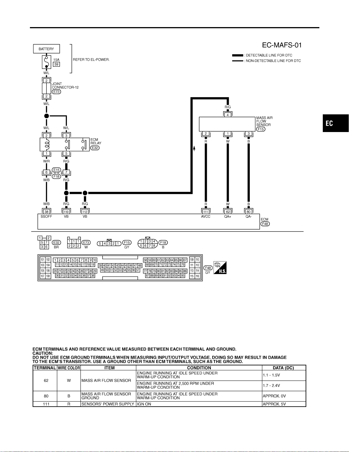
Wiring Diagram
NFEC0846
MEC473D
SEF650XC
GI
MA
EM
LC
FE
CL
MT
AT
AX
SU
BR
ST
RS
BT
HA
SC
EL
IDX
DTC P0101 MAF SENSOR
Wiring Diagram
EC-191
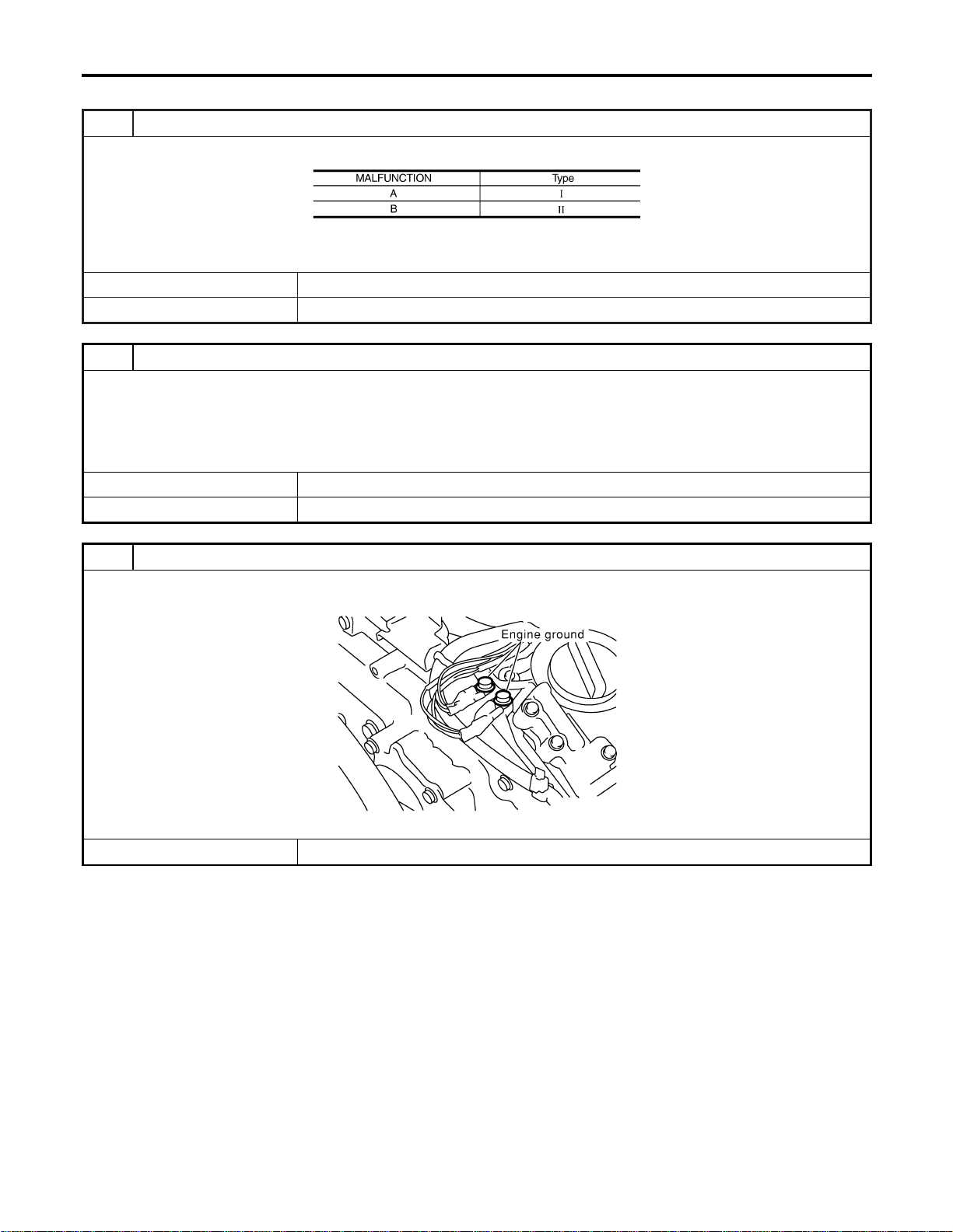
Diagnostic Procedure
NFEC0847
1 INSPECTION START
Which malfunction (A, B) is duplicated?
MTBL1142
Type I or Type II
Type I © GO TO 3.
Type II © GO TO 2.
2 CHECK INTAKE SYSTEM
Check the following for connection.
I Air duct
I Vacuum hoses
I Intake air passage between air duct to intake manifold collector
OK or NG
OK © GO TO 3.
NG © Reconnect the parts.
3 RETIGHTEN GROUND SCREWS
1. Turn ignition switch “OFF”.
2. Loosen and retighten engine ground screws.
SEC047D
© GO TO 4.
DTC P0101 MAF SENSOR
Diagnostic Procedure
EC-192
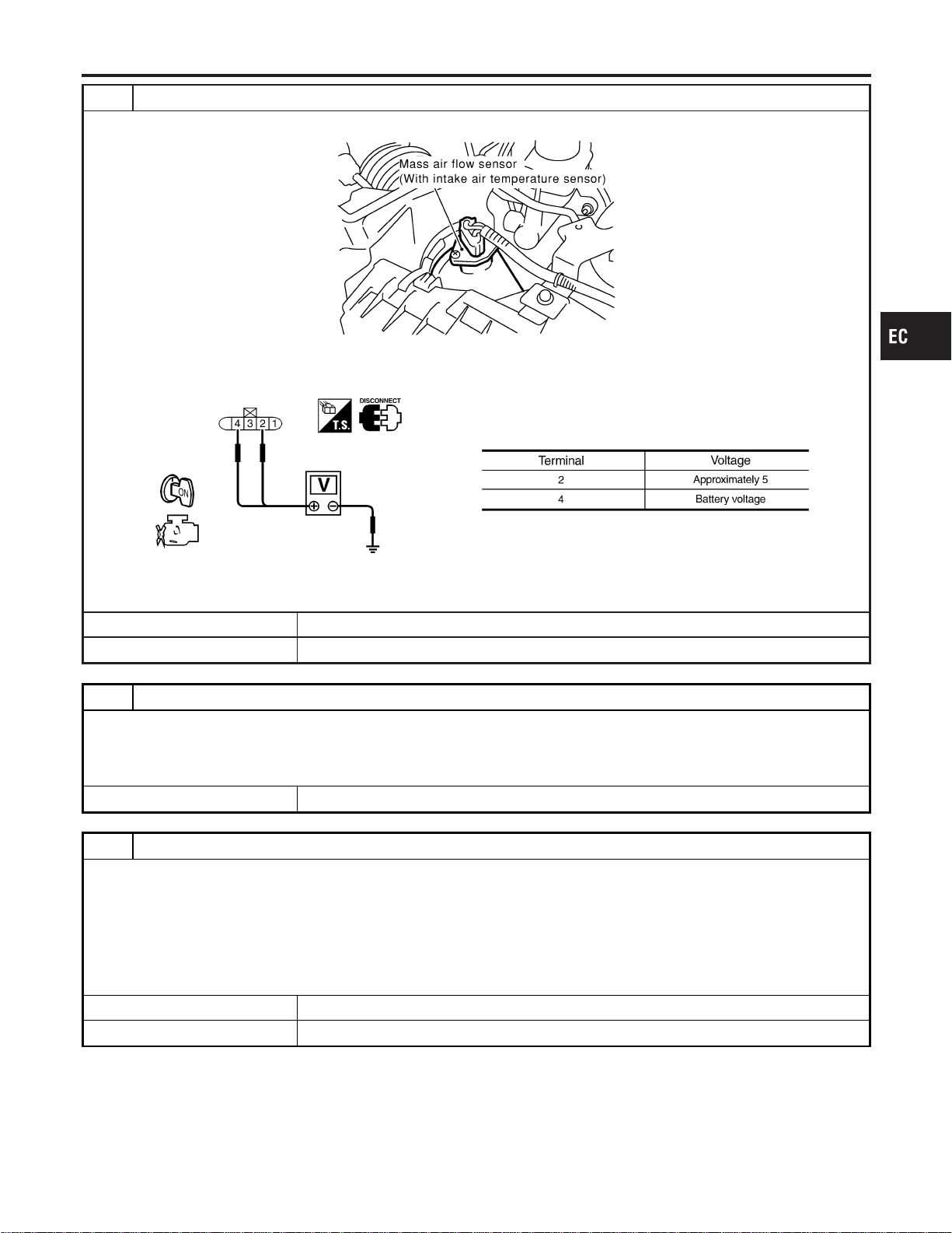
4 CHECK MAF SENSOR POWER SUPPLY CIRCUIT
1. Disconnect mass air flow (MAF) sensor harness connector.
SEC055D
2. Turn ignition switch “ON”.
3. Check voltage between MAF sensor terminals 2, 4 and ground with CONSULT-II or tester.
SEF297X
OK or NG
OK © GO TO 6.
NG © GO TO 5.
5 DETECT MALFUNCTIONING PART
Check the following.
I Harness connectors E15, F18
I Harness for open or short between ECM relay and mass air flow sensor
I Harness for open or short between mass air flow sensor and ECM
© Repair harness or connectors.
6 CHECK MAF SENSOR GROUND CIRCUIT FOR OPEN AND SHORT
1. Turn ignition switch “OFF”.
2. Disconnect ECM harness connector.
3. Check harness continuity between MAF sensor terminal 3 and ECM terminal 80.
Refer to Wiring Diagram.
Continuity should exist.
4. Also check harness for short to power.
OK or NG
OK © GO TO 7.
NG © Repair open circuit or short to power in harness or connectors.
GI
MA
EM
LC
FE
CL
MT
AT
AX
SU
BR
ST
RS
BT
HA
SC
EL
IDX
DTC P0101 MAF SENSOR
Diagnostic Procedure (Cont’d)
EC-193
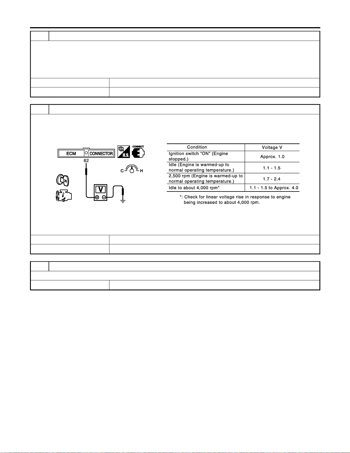
7 CHECK MAF SENSOR INPUT SIGNAL CIRCUIT FOR OPEN AND SHORT
1. Check harness continuity between MAF sensor terminal 1 and ECM terminal 62.
Refer to Wiring Diagram.
Continuity should exist.
2. Also check harness for short to ground and short to power.
OK or NG
OK © GO TO 8.
NG © Repair open circuit or short to ground or short to power in harness or connectors.
8 CHECK MASS AIR FLOW SENSOR
1. Reconnect harness connectors disconnected.
2. Start engine and warm it up to normal operating temperature.
3. Check voltage between ECM terminal 62 (Mass air flow sensor signal) and ground.
SEC103D
4. If the voltage is out of specification, disconnect MAF sensor harness connector and connect it again.
Then repeat above check.
OK or NG
OK © GO TO 9.
NG © Replace mass air flow sensor.
9 CHECK INTERMITTENT INCIDENT
Refer to “TROUBLE DIAGNOSIS FOR INTERMITTENT INCIDENT”, EC-156.
© INSPECTION END
DTC P0101 MAF SENSOR
Diagnostic Procedure (Cont’d)
EC-194
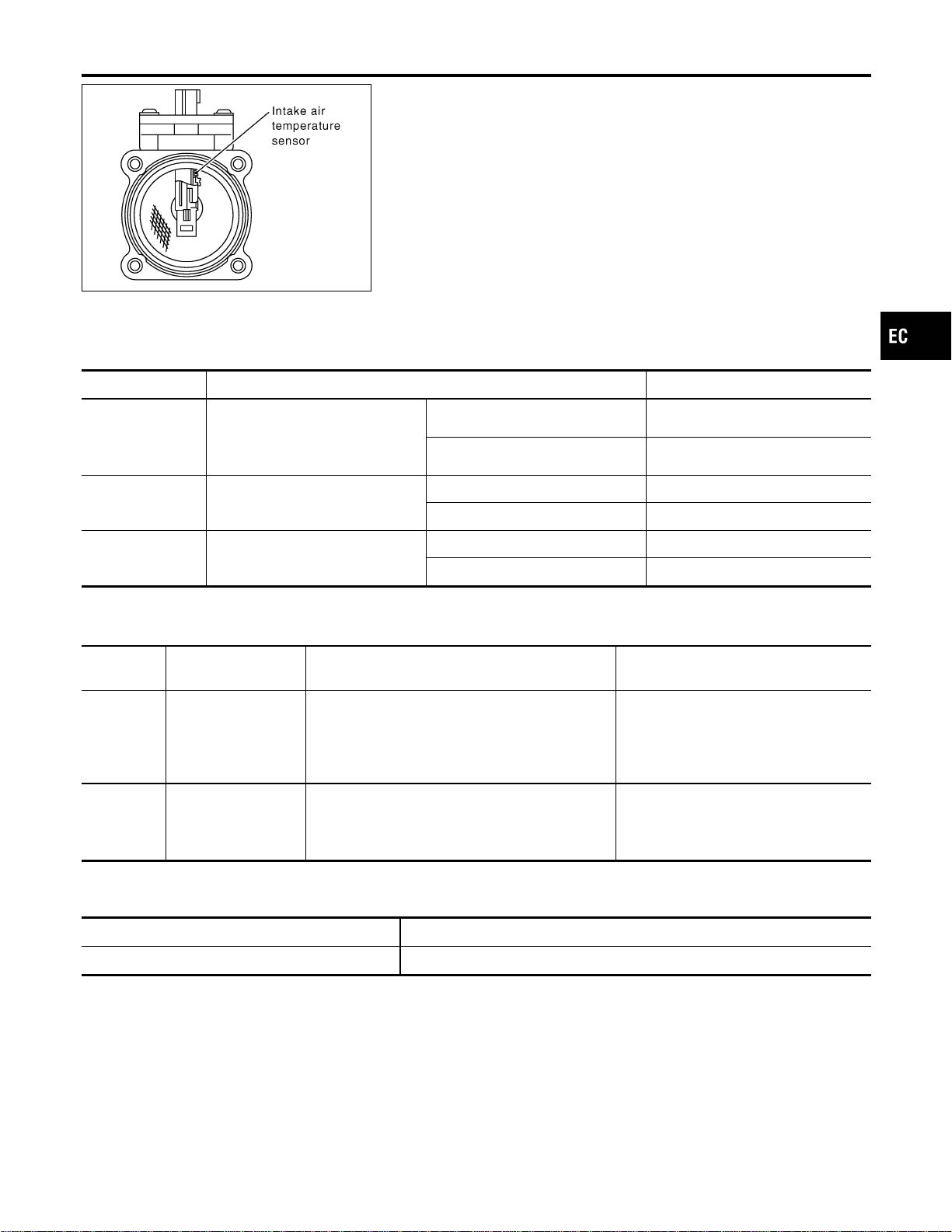
SEC266C
Component Description
NFEC0746
The mass air flow sensor is placed in the stream of intake air. It
measures the intake flow rate by measuring a part of the entire
intake flow. It consists of a hot film that is supplied with electric
current from the ECM. The temperature of the hot film is controlled
by the ECM a certain amount. The heat generated by the hot film
is reduced as the intake air flows around it. The more air, the
greater the heat loss.
Therefore, the ECM must supply more electric current to maintain
the temperature of the hot film as air flow increases. The ECM
detects the air flow by means of this current change.
CONSULT-II Reference Value in Data Monitor
Mode
NFEC0747
Specification data are reference values.
MONITOR ITEM CONDITION SPECIFICATION
MAS A/F SE-B1
I Engine: After warming up
I Air conditioner switch: “OFF”
I Shift lever: “N”
I No-load
Idle 1.1 - 1.5V
2,500 rpm 1.7 - 2.4V
CAL/LD VALUE ditto
Idle 10 - 35%
2,500 rpm 10 - 35%
MASS AIRFLOW ditto
Idle 2.0 - 6.0 g·m/s
2,500 rpm 7.0 - 20.0 g·m/s
On Board Diagnosis Logic
NFEC1429
These self-diagnoses have the one trip detection logic.
DTC No.
Trouble diagnosis
name
DTC Detecting Condition Possible Cause
P0102
0102
Mass air flow sensor
circuit low input
An excessively low voltage from the sensor is sent
to ECM when engine is running.
I Harness or connectors
(The sensor circuit is open or
shorted.)
I Intake air leaks
I Mass air flow sensor
P0103
0103
Mass air flow sensor
circuit high input
An excessively high voltage from the sensor is
sent to ECM.
I Harness or connectors
(The sensor circuit is open or
shorted.)
I Mass air flow sensor
FAIL-SAFE MODE
NFEC1429S01
When the malfunction is detected, the ECM enters fail-safe mode and the MIL lights up.
Detected items Engine operating condition in fail-safe mode
Mass air flow sensor circuit Engine speed will not rise more than 2,400 rpm due to the fuel cut.
GI
MA
EM
LC
FE
CL
MT
AT
AX
SU
BR
ST
RS
BT
HA
SC
EL
IDX
DTC P0102, P0103 MAF SENSOR
Component Description
EC-195
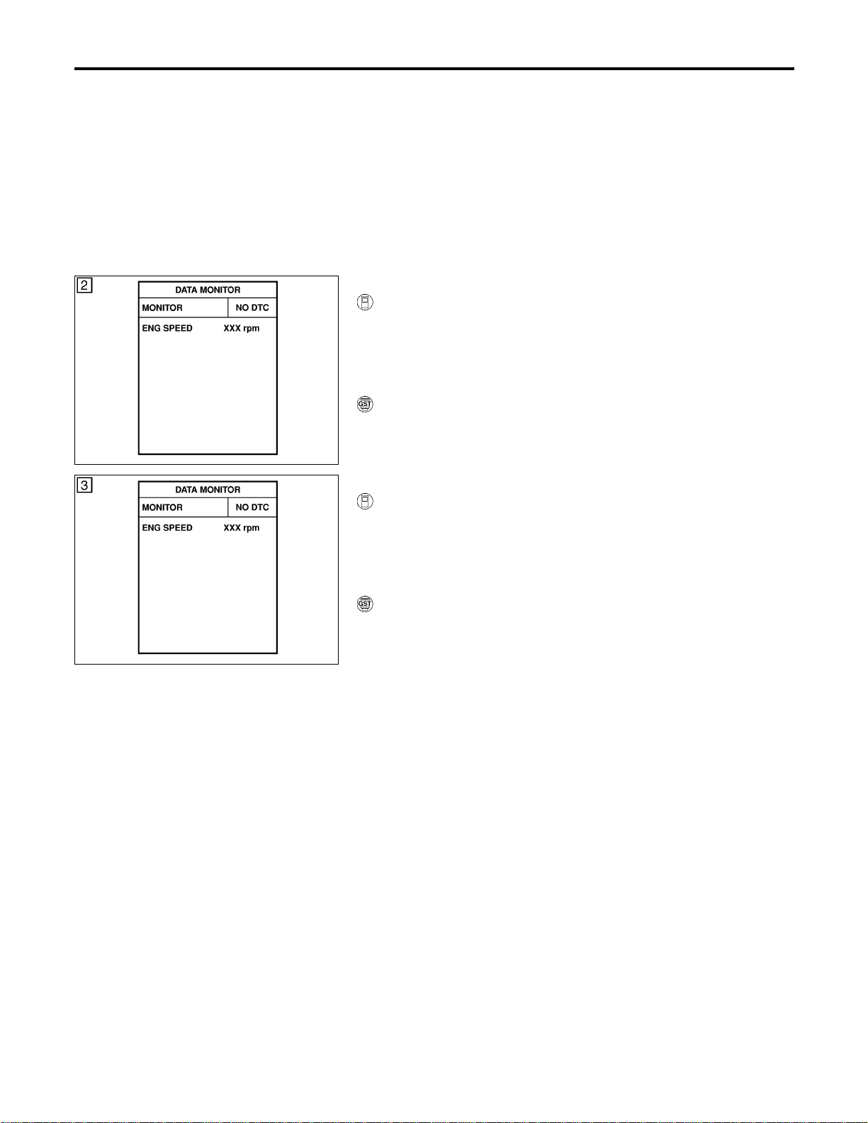
DTC Confirmation Procedure
NFEC1430
NOTE:
If “DTC Confirmation Procedure” has been previously conducted,
always turn ignition switch “OFF” and wait at least 10 seconds
before conducting the next test.
SEF058Y
PROCEDURE FOR DTC P0103
NFEC1430S01
With CONSULT-II
NFEC1430S0101
1) Turn ignition switch “ON”.
2) Select “DATA MONITOR” mode with CONSULT-II.
3) Wait at least 6 seconds.
4) If DTC is detected, go to “Diagnostic Procedure”, EC-198.
With GST
NFEC1430S0102
Follow the procedure “With CONSULT-II” above.
SEF058Y
PROCEDURE FOR DTC P0102
NFEC1430S02
With CONSULT-II
NFEC1430S0201
1) Turn ignition switch “ON”.
2) Select “DATA MONITOR” mode with CONSULT-II.
3) Start engine and wait 5 seconds at most.
4) If DTC is detected, go to “Diagnostic Procedure”, EC-198.
With GST
NFEC1430S0202
Follow the procedure “With CONSULT-II” above.
DTC P0102, P0103 MAF SENSOR
DTC Confirmation Procedure
EC-196
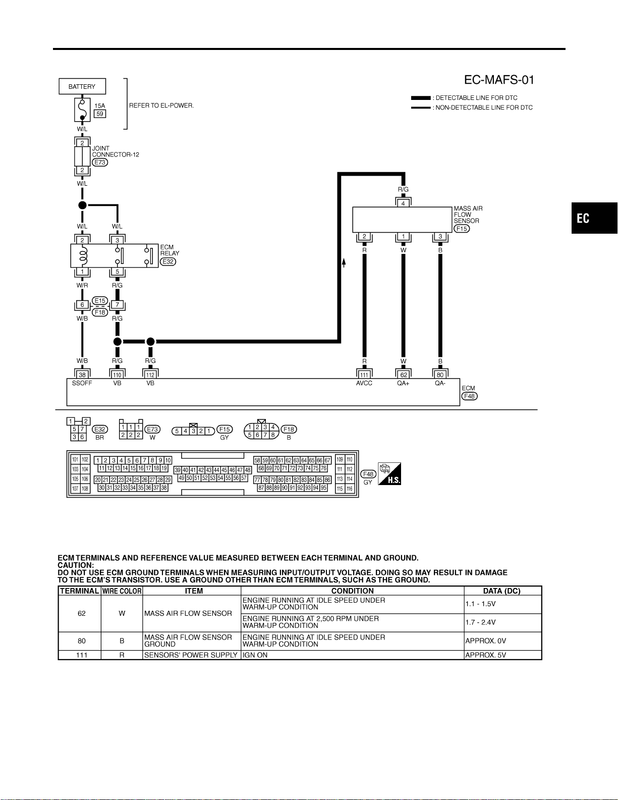
Wiring Diagram
NFEC0753
MEC473D
SEF650XC
GI
MA
EM
LC
FE
CL
MT
AT
AX
SU
BR
ST
RS
BT
HA
SC
EL
IDX
DTC P0102, P0103 MAF SENSOR
Wiring Diagram
EC-197
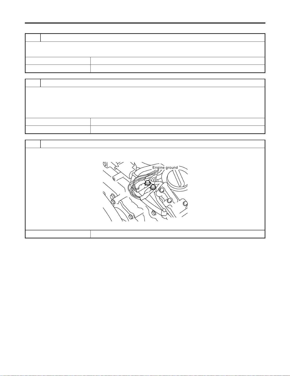
Diagnostic Procedure
NFEC0754
1 INSPECTION START
Which malfunction (P0102 or P0103) is duplicated?
P0102 or P0103
P0103 © GO TO 3.
P0102 © GO TO 2.
2 CHECK INTAKE SYSTEM
Check the following for connection.
I Air duct
I Vacuum hoses
I Intake air passage between air duct to intake manifold collector
OK or NG
OK © GO TO 3.
NG © Reconnect the parts.
3 RETIGHTEN GROUND SCREWS
1. Turn ignition switch “OFF”.
2. Loosen and retighten engine ground screws.
SEC047D
© GO TO 4.
DTC P0102, P0103 MAF SENSOR
Diagnostic Procedure
EC-198
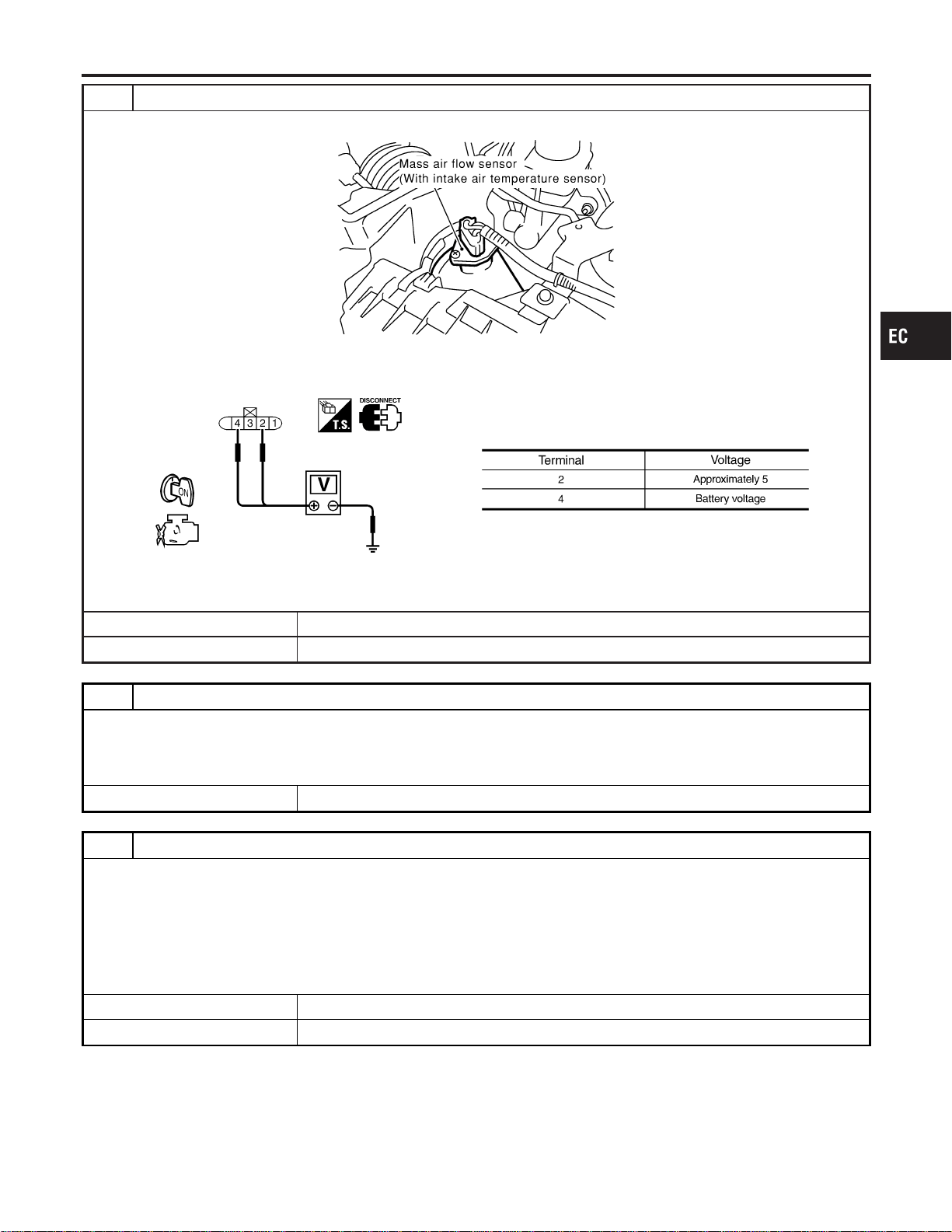
4 CHECK MAF SENSOR POWER SUPPLY CIRCUIT
1. Disconnect mass air flow (MAF) sensor harness connector.
SEC055D
2. Turn ignition switch “ON”.
3. Check voltage between MAF sensor terminals 2, 4 and ground with CONSULT-II or tester.
SEF297X
OK or NG
OK © GO TO 6.
NG © GO TO 5.
5 DETECT MALFUNCTIONING PART
Check the following.
I Harness connectors E15, F18
I Harness for open or short between ECM relay and mass air flow sensor
I Harness for open or short between mass air flow sensor and ECM
© Repair harness or connectors.
6 CHECK MAF SENSOR GROUND CIRCUIT FOR OPEN AND SHORT
1. Turn ignition switch “OFF”.
2. Disconnect ECM harness connector.
3. Check harness continuity between MAF sensor terminal 3 and ECM terminal 80.
Refer to Wiring Diagram.
Continuity should exist.
4. Also check harness for short to power.
OK or NG
OK © GO TO 7.
NG © Repair open circuit or short to power in harness or connectors.
GI
MA
EM
LC
FE
CL
MT
AT
AX
SU
BR
ST
RS
BT
HA
SC
EL
IDX
DTC P0102, P0103 MAF SENSOR
Diagnostic Procedure (Cont’d)
EC-199
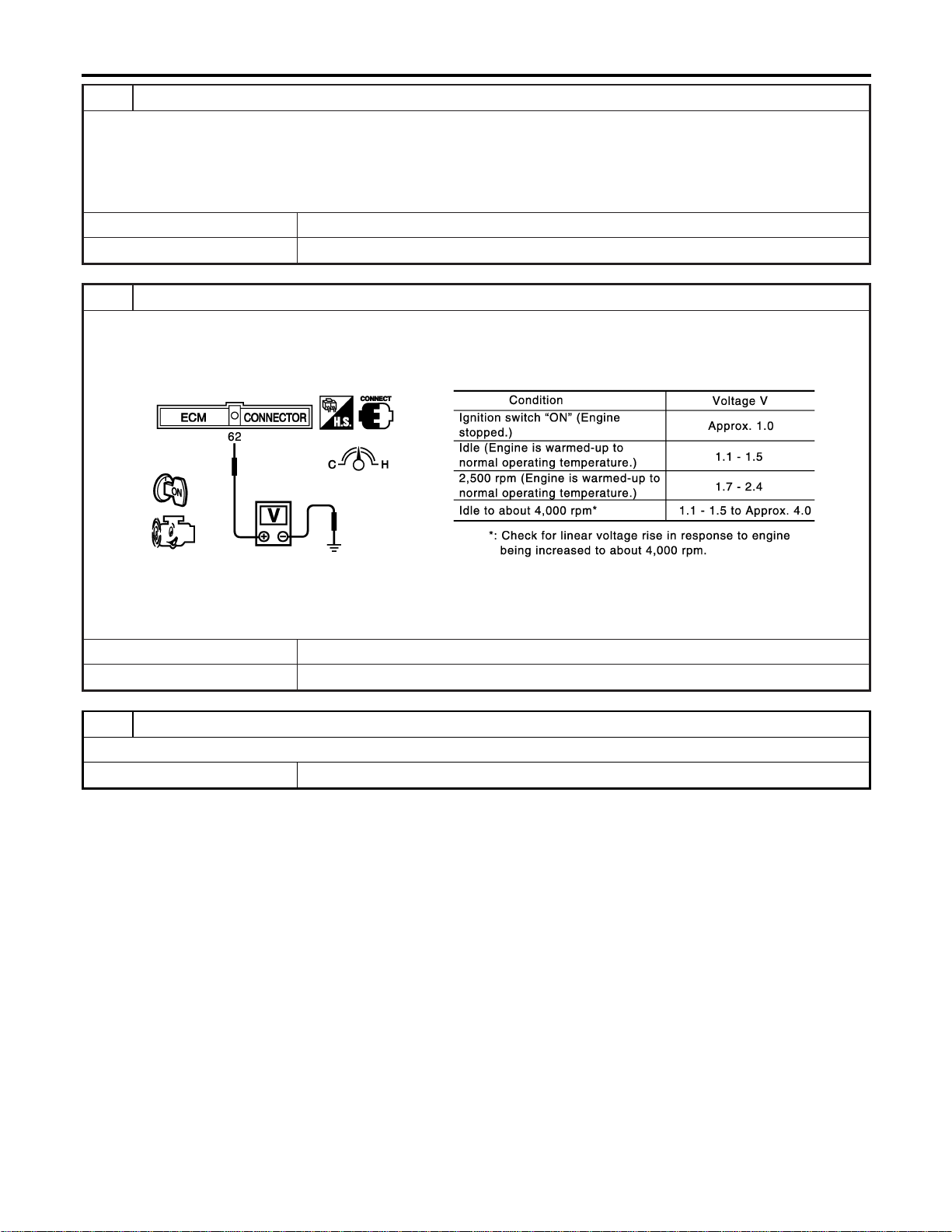
7 CHECK MAF SENSOR INPUT SIGNAL CIRCUIT FOR OPEN AND SHORT
1. Check harness continuity between MAF sensor terminal 1 and ECM terminal 62.
Refer to Wiring Diagram.
Continuity should exist.
2. Also check harness for short to ground and short to power.
OK or NG
OK © GO TO 8.
NG © Repair open circuit or short to ground or short to power in harness or connectors.
8 CHECK MASS AIR FLOW SENSOR
1. Reconnect harness connectors disconnected.
2. Start engine and warm it up to normal operating temperature.
3. Check voltage between ECM terminal 62 (Mass air flow sensor signal) and ground.
SEC103D
4. If the voltage is out of specification, disconnect MAF sensor harness connector and connect it again.
Then repeat above check.
OK or NG
OK © GO TO 9.
NG © Replace mass air flow sensor.
9 CHECK INTERMITTENT INCIDENT
Refer to “TROUBLE DIAGNOSIS FOR INTERMITTENT INCIDENT”, EC-156.
© INSPECTION END
DTC P0102, P0103 MAF SENSOR
Diagnostic Procedure (Cont’d)
EC-200
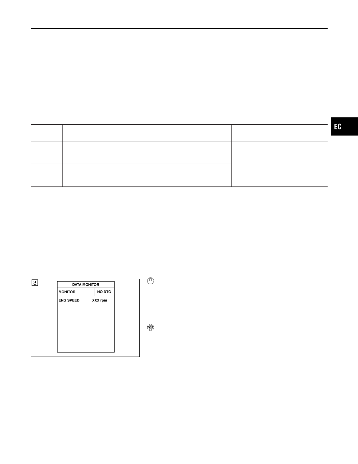
Component Description
NFEC0848
The absolute pressure sensor is built into ECM. The sensor detects
ambient barometric pressure and sends the voltage signal to the
microcomputer.
On Board Diagnosis Logic
NFEC0849
DTC No.
Trouble diagnosis
name
DTC Detecting Condition Possible Cause
P0107
0107
Absolute pressure
sensor circuit low
input
An excessively low voltage from the sensor is sent
to ECM.
I Harness or connectors
(The sensor circuit is open or
shorted.)
I Absolute pressure sensor
P0108
0108
Absolute pressure
sensor circuit high
input
An excessively high voltage from the sensor is
sent to ECM.
DTC Confirmation Procedure
NFEC0850
NOTE:
If “DTC Confirmation Procedure” has been previously conducted,
always turn ignition switch OFF and wait at least 10 seconds before
conducting the next test.
SEF058Y
With CONSULT-II
1) Turn ignition switch ON.
2) Select “DATA MONITOR” mode with CONSULT-II.
3) Wait at least 6 seconds.
4) If 1st trip DTC is detected, go to “Diagnostic Procedure”,
EC-202.
With GST
Follow the procedure “With CONSULT-II”.
GI
MA
EM
LC
FE
CL
MT
AT
AX
SU
BR
ST
RS
BT
HA
SC
EL
IDX
DTC P0107, P0108 ABSOLUTE PRESSURE SENSOR
Component Description
EC-201
Diagnostic Procedure
NFEC0851
1 INSPECTION START
With CONSULT-II
1. Turn ignition switch ON.
2. Select “SELF DIAG RESULTS” mode with CONSULT-II.
3. Touch “ERASE”.
4. Perform “DTC Confirmation Procedure”.
See EC-201.
5. Is the 1st trip DTC P0107 or P0108 displayed again?
With GST
1. Turn ignition switch ON.
2. Select MODE 4 with GST.
3. Touch “ERASE”.
4. Perform “DTC Confirmation Procedure”.
See EC-201.
5. Is the 1st trip DTC P0107 or P0108 displayed again?
YesorNo
Yes © GO TO 2.
No © INSPECTION END
2 REPLACE ECM
1. Replace ECM.
2. Perform initialization of NVIS (NATS) system and registration of all NVIS (NATS) ignition key IDs. Refer to “NVIS (NIS-
SAN VEHICLE IMMOBILIZER SYSTEM — NATS)”, EC-92.
3. Perform “Accelerator Pedal Released Position Learning”, EC-71.
4. Perform “Throttle Valve Closed Position Learning”, EC-71.
5. Perform “Idle Air Volume Learning”, EC-71.
© INSPECTION END
DTC P0107, P0108 ABSOLUTE PRESSURE SENSOR
Diagnostic Procedure
EC-202
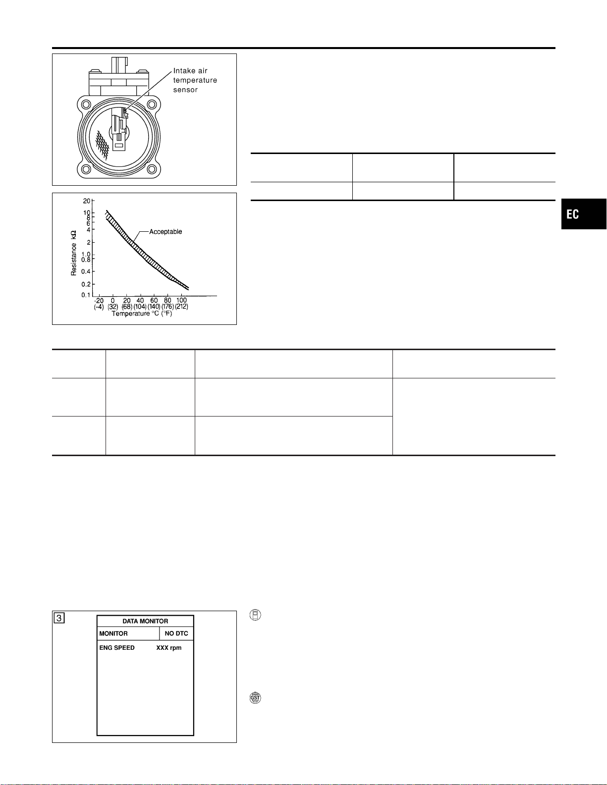
SEC266C
SEF012P
Component Description
NFEC0852
The intake air temperature sensor is mounted to the air duct hous-
ing. The sensor detects intake air temperature and transmits a sig-
nal to the ECM.
The temperature sensing unit uses a thermistor which is sensitive
to the change in temperature. Electrical resistance of the thermistor
decreases in response to the temperature rise.
<Reference data>
Intake air
temperature °C (°F)
Voltage* V Resistance kΩ
25 (77) 3.32 1.9 - 2.1
*: These data are reference values and are measured between ECM terminal 66
(Intake air temperature sensor) and body ground.
CAUTION:
Do not use ECM ground terminals when measuring input/
output voltage. Doing so may result in damage to the ECM’s
transistor. Use a ground other than ECM terminals, such as
the ground.
On Board Diagnosis Logic
NFEC0853
DTC No.
Trouble diagnosis
name
DTC Detecting Condition Possible Cause
P0112
0112
Intake air temperature
sensor circuit low
input
An excessively low voltage from the sensor is sent
to ECM.
I Harness or connectors
(The sensor circuit is open or
shorted.)
I Intake air temperature sensor
P0113
0113
Intake air temperature
sensor circuit high
input
An excessively high voltage from the sensor is
sent to ECM.
DTC Confirmation Procedure
NFEC0854
NOTE:
If “DTC Confirmation Procedure” has been previously conducted,
always turn ignition switch “OFF” and wait at least 10 seconds
before conducting the next test.
SEF058Y
WITH CONSULT-II
NFEC0854S01
1) Turn ignition switch “ON”.
2) Select “DATA MONITOR” mode with CONSULT-II.
3) Wait at least 5 seconds.
4) If 1st trip DTC is detected, go to “Diagnostic Procedure”,
EC-205.
WITH GST
NFEC0854S02
Follow the procedure “With CONSULT-II” above.
GI
MA
EM
LC
FE
CL
MT
AT
AX
SU
BR
ST
RS
BT
HA
SC
EL
IDX
DTC P0112, P0113 IAT SENSOR
Component Description
EC-203
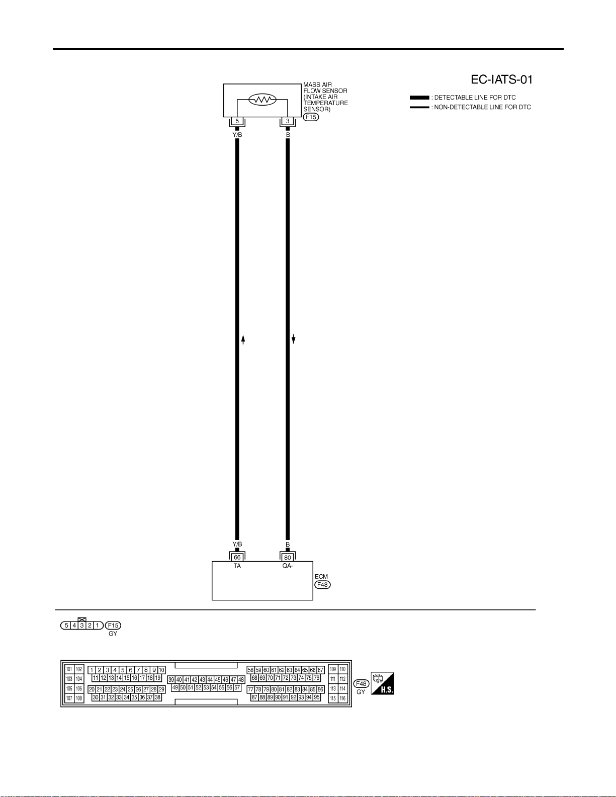
Wiring Diagram
NFEC0855
MEC474D
DTC P0112, P0113 IAT SENSOR
Wiring Diagram
EC-204
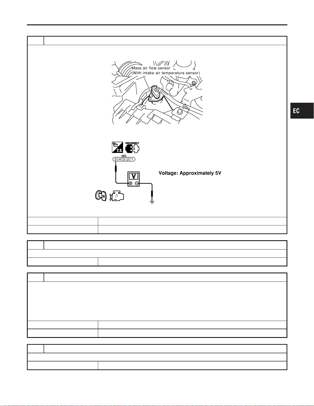
Diagnostic Procedure
NFEC0856
1 CHECK INTAKE AIR TEMPERATURE SENSOR POWER SUPPLY CIRCUIT
1. Turn ignition switch “OFF”.
2. Disconnect intake air temperature sensor harness connector.
SEC055D
3. Turn ignition switch “ON”.
4. Check voltage between terminal 1 and ground.
SEC104D
OK or NG
OK © GO TO 3.
NG © GO TO 2.
2 DETECT MALFUNCTIONING PART
Check harness for open or short between ECM and intake air temperature sensor.
© Repair harness or connectors.
3 CHECK INTAKE AIR TEMPERATURE SENSOR GROUND CIRCUIT FOR OPEN AND SHORT
1. Turn ignition switch “OFF”.
2. Check harness continuity between sensor terminal 3 and engine ground.
Refer to Wiring Diagram.
Continuity should exist.
3. Also check harness for short to power.
OK or NG
OK © GO TO 5.
NG © GO TO 4.
4 DETECT MALFUNCTIONING PART
Check harness for open between ECM and intake air temperature sensor.
© Repair open circuit or short to power in harness or connectors.
GI
MA
EM
LC
FE
CL
MT
AT
AX
SU
BR
ST
RS
BT
HA
SC
EL
IDX
DTC P0112, P0113 IAT SENSOR
Diagnostic Procedure
EC-205
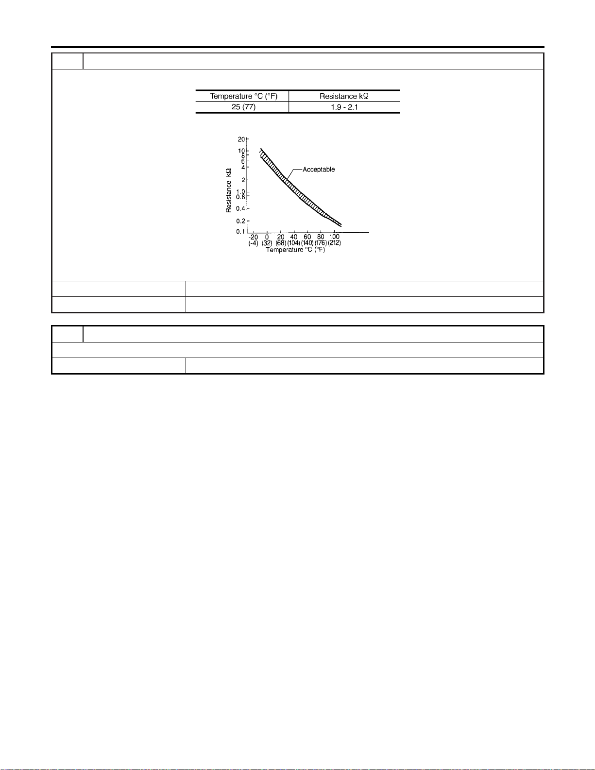
5 CHECK INTAKE AIR TEMPERATURE SENSOR
Check resistance between intake air temperature sensor terminals 3 and 5 as shown in the figure.
MTBL1143
SEF012P
OK or NG
OK © GO TO 6.
NG © Replace intake air temperature sensor.
6 CHECK INTERMITTENT INCIDENT
Refer to “TROUBLE DIAGNOSIS FOR INTERMITTENT INCIDENT”, EC-156.
© INSPECTION END
DTC P0112, P0113 IAT SENSOR
Diagnostic Procedure (Cont’d)
EC-206
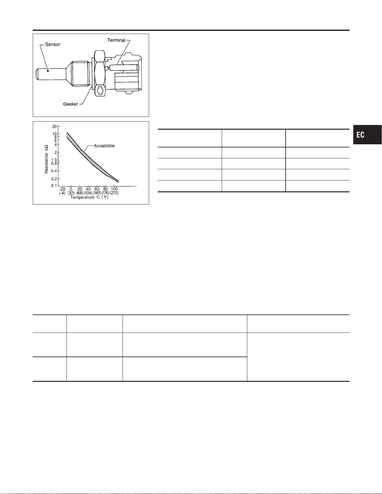
SEF594K
Component Description
NFEC0857
The engine coolant temperature sensor is used to detect the
engine coolant temperature. The sensor modifies a voltage signal
from the ECM. The modified signal returns to the ECM as the
engine coolant temperature input. The sensor uses a thermistor
which is sensitive to the change in temperature. The electrical
resistance of the thermistor decreases as temperature increases.
SEF012P
<Reference data>
Engine coolant
temperature °C (°F)
Voltage* V Resistance kΩ
−10 (14) 4.4 7.0 - 11.4
20 (68) 3.5 2.1 - 2.9
50 (122) 2.2 0.68 - 1.00
90 (194) 0.9 0.236 - 0.260
*: These data are reference values and are measured between ECM terminal 93
(Engine coolant temperature sensor) and ground.
CAUTION:
Do not use ECM ground terminals when measuring input/
output voltage. Doing so may result in damage to the ECM’s
transistor. Use a ground other than ECM terminals, such as
the ground.
On Board Diagnosis Logic
NFEC1431
These self-diagnoses have the one trip detection logic.
DTC No.
Trouble diagnosis
name
DTC Detecting Condition Possible Cause
P0117
0117
Engine coolant tem-
perature sensor cir-
cuit low input
An excessively low voltage from the sensor is sent
to ECM.
I Harness or connectors
(The sensor circuit is open or
shorted.)
I Engine coolant temperature sensor
P0118
0118
Engine coolant tem-
perature sensor cir-
cuit high input
An excessively high voltage from the sensor is
sent to ECM.
FAIL-SAFE MODE
NFEC1431S01
When this malfunction is detected, the ECM enters fail-safe mode and the MIL lights up.
GI
MA
EM
LC
FE
CL
MT
AT
AX
SU
BR
ST
RS
BT
HA
SC
EL
IDX
DTC P0117, P0118 ECT SENSOR
Component Description
EC-207
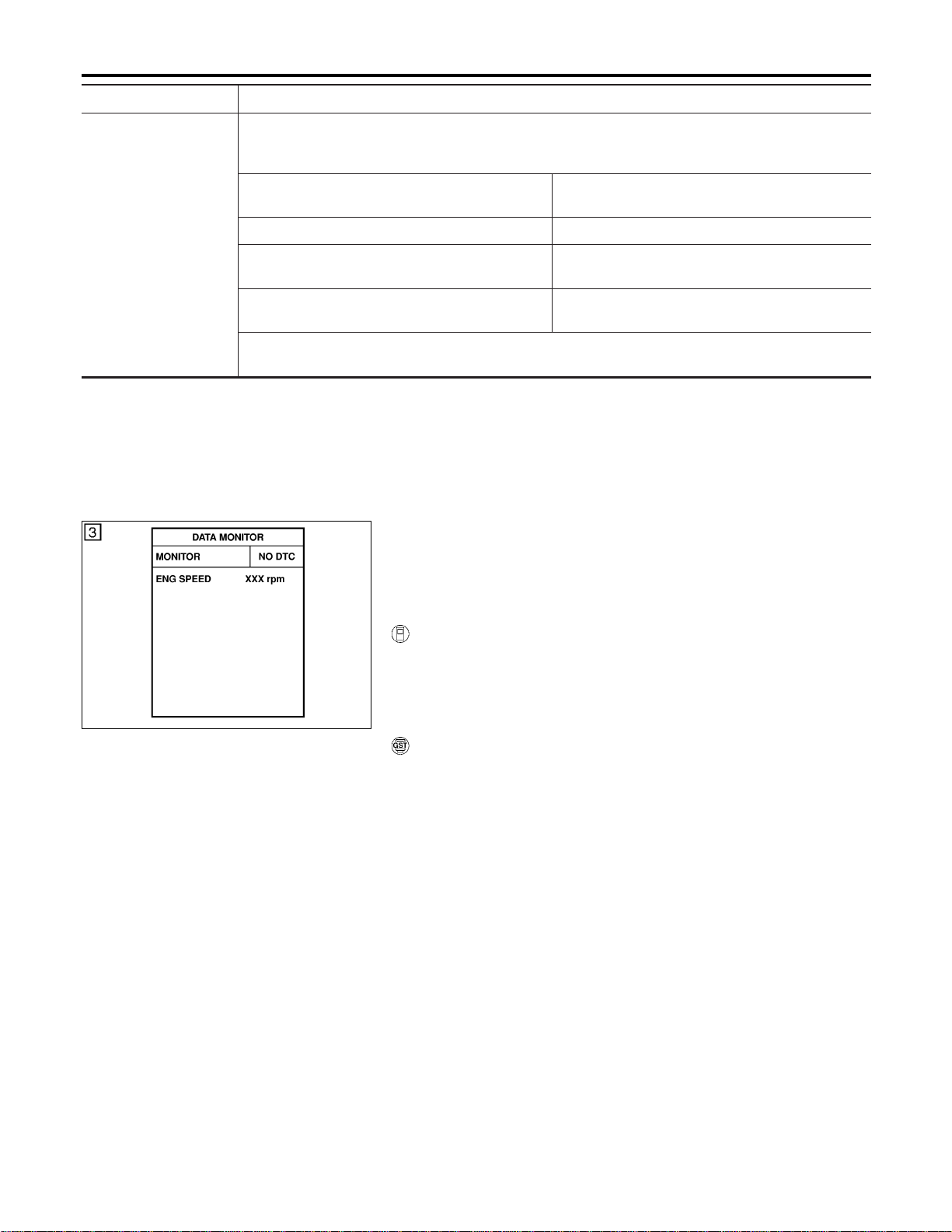
Detected items Engine operating condition in fail-safe mode
Engine coolant tem-
perature sensor circuit
Engine coolant temperature will be determined by ECM based on the time after turning ignition switch
“ON” or “START”.
CONSULT-II displays the engine coolant temperature decided by ECM.
Condition
Engine coolant temperature decided (CONSULT-II
display)
Just as ignition switch is turned ON or Start 40°C (104°F)
More than approx. 4 minutes after ignition ON or
Start
80°C (176°F)
Except as shown above
40 - 80°C (104 - 176°F)
(Depends on the time)
When the fail-safe system for engine coolant temperature sensor is activated, the cooling fan operates
while engine is running.
SEF058Y
DTC Confirmation Procedure
NFEC1432
NOTE:
If “DTC Confirmation Procedure” has been previously conducted,
always turn ignition switch “OFF” and wait at least 10 seconds
before conducting the next test.
WITH CONSULT-II
NFEC1432S01
1) Turn ignition switch “ON”.
2) Select “DATA MONITOR” mode with CONSULT-II.
3) Wait at least 5 seconds.
4) If DTC is detected, go to “Diagnostic Procedure”, EC-210.
WITH GST
NFEC1432S02
Follow the procedure “WITH CONSULT-II” above.
DTC P0117, P0118 ECT SENSOR
On Board Diagnosis Logic (Cont’d)
EC-208
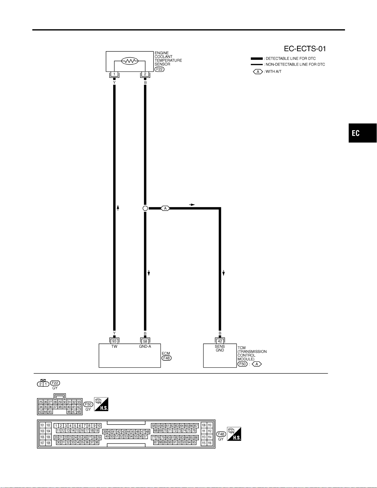
Wiring Diagram
NFEC0860
MEC475D
GI
MA
EM
LC
FE
CL
MT
AT
AX
SU
BR
ST
RS
BT
HA
SC
EL
IDX
DTC P0117, P0118 ECT SENSOR
Wiring Diagram
EC-209
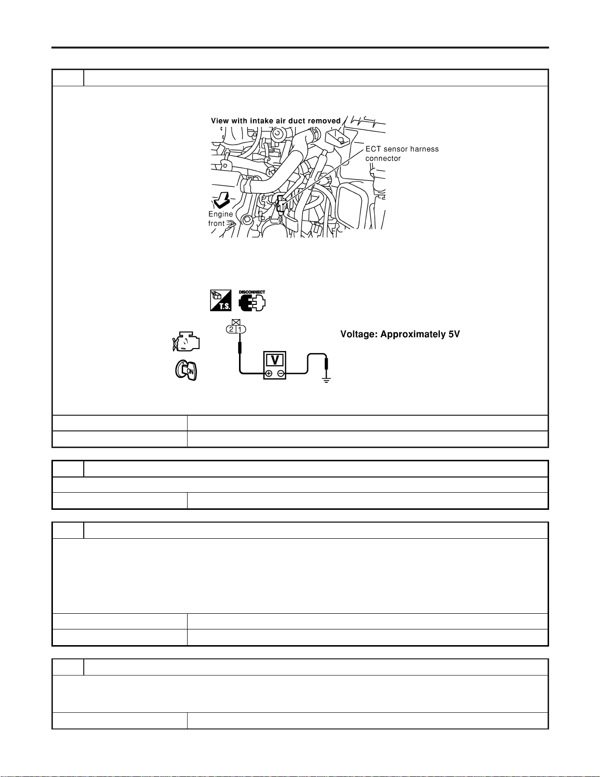
Diagnostic Procedure
NFEC0861
1 CHECK ECT SENSOR POWER SUPPLY CIRCUIT
1. Turn ignition switch “OFF”.
2. Disconnect engine coolant temperature (ECT) sensor harness connector.
SEC105D
3. Turn ignition switch “ON”.
4. Check voltage between ECT sensor harness connector terminal 1 and ground with CONSULT-II or tester.
SEC106D
OK or NG
OK © GO TO 3.
NG © GO TO 2.
2 DETECT MALFUNCTIONING PART
Check harness for open or short between ECM and engine coolant temperature sensor.
© Repair harness or connectors.
3 CHECK ECT SENSOR GROUND CIRCUIT FOR OPEN AND SHORT
1. Turn ignition switch “OFF”.
2. Check harness continuity between ECT sensor terminal 2 and engine ground.
Refer to Wiring Diagram.
Continuity should exist.
3. Also check harness for short to power.
OK or NG
OK © GO TO 5.
NG © GO TO 4.
4 DETECT MALFUNCTIONING PART
Check the following.
I Harness for open between ECM and engine coolant temperature sensor
I Harness for open between TCM (Transmission Control Module) and engine coolant temperature sensor
© Repair open circuit or short to power in harness or connectors.
DTC P0117, P0118 ECT SENSOR
Diagnostic Procedure
EC-210
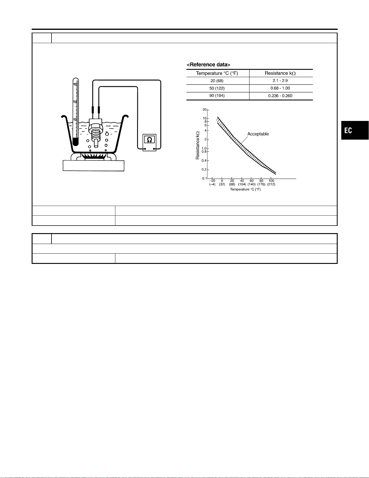
5 CHECK ENGINE COOLANT TEMPERATURE SENSOR
Check resistance between engine coolant temperature sensor terminals 1 and 2 as shown in the figure.
SEF304X
OK or NG
OK © GO TO 6.
NG © Replace engine coolant temperature sensor.
6 CHECK INTERMITTENT INCIDENT
Refer to “TROUBLE DIAGNOSIS FOR INTERMITTENT INCIDENT”, EC-156.
© INSPECTION END
GI
MA
EM
LC
FE
CL
MT
AT
AX
SU
BR
ST
RS
BT
HA
SC
EL
IDX
DTC P0117, P0118 ECT SENSOR
Diagnostic Procedure (Cont’d)
EC-211

Description
NFEC1412
DTC P0121, P0122 or P0123 is displayed with other DTC.
First perform the trouble diagnosis for displayed other DTC.
DTC P0121, P0122, P0123
Description
EC-212
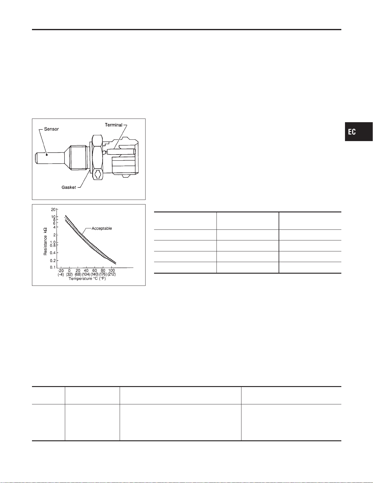
Description
NFEC0869
NOTE:
If DTC P0125 is displayed with P0117, P0118, first perform the
trouble diagnosis for DTC P0117, P0118. Refer to EC-207.
SEF594K
COMPONENT DESCRIPTION
NFEC0869S01
The engine coolant temperature sensor is used to detect the
engine coolant temperature. The sensor modifies a voltage signal
from the ECM. The modified signal returns to the ECM as the
engine coolant temperature input. The sensor uses a thermistor
which is sensitive to the change in temperature. The electrical
resistance of the thermistor decreases as temperature increases.
SEF012P
<Reference data>
Engine coolant
temperature °C (°F)
Voltage* V Resistance kΩ
−10 (14) 4.4 7.0 - 11.4
20 (68) 3.5 2.1 - 2.9
50 (122) 2.2 0.68 - 1.00
90 (194) 0.9 0.236 - 0.260
*: These data are reference values and are measured between ECM terminal 93
(Engine coolant temperature sensor) and ground.
CAUTION:
Do not use ECM ground terminals when measuring input/
output voltage. Doing so may result in damage to the ECM’s
transistor. Use a ground other than ECM terminals, such as
the ground.
On Board Diagnosis Logic
NFEC0870
DTC No.
Trouble diagnosis
name
DTC Detecting Condition Possible Cause
P0125
0125
Insufficient engine
coolant temperature
for closed loop fuel
control
I Voltage sent to ECM from the sensor is not
practical, even when some time has passed
after starting the engine.
I Engine coolant temperature is insufficient for
closed loop fuel control.
I Harness or connectors
(The sensor circuit is open or
shorted.)
I Engine coolant temperature sensor
I Thermostat
GI
MA
EM
LC
FE
CL
MT
AT
AX
SU
BR
ST
RS
BT
HA
SC
EL
IDX
DTC P0125 ECT SENSOR
Description
EC-213
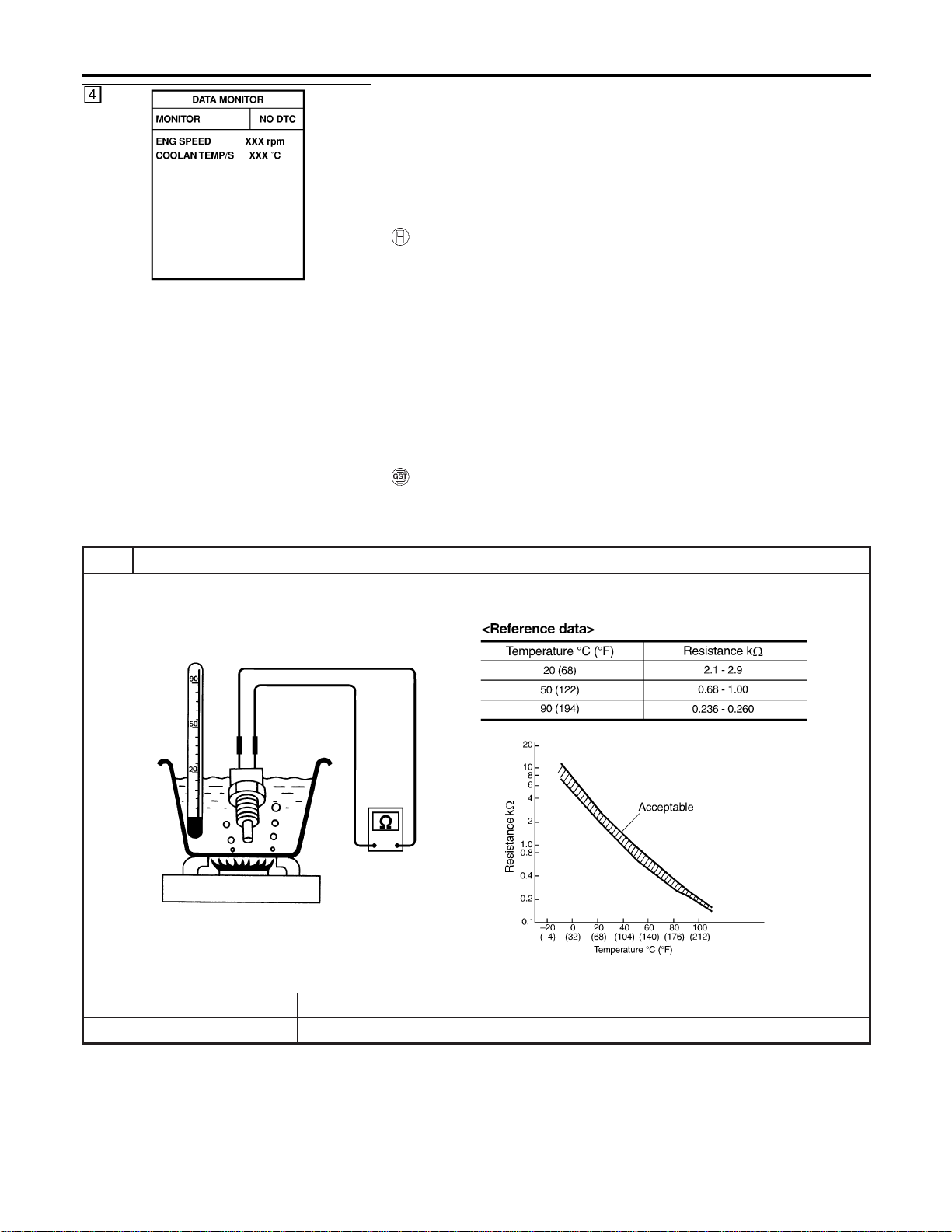
SEF174Y
DTC Confirmation Procedure
NFEC0871
CAUTION:
Be careful not to overheat engine.
NOTE:
If “DTC Confirmation Procedure” has been previously conducted,
always turn ignition switch “OFF” and wait at least 10 seconds
before conducting the next test.
WITH CONSULT-II
NFEC0871S01
1) Turn ignition switch “ON”.
2) Select “DATA MONITOR” mode with CONSULT-II.
3) Check that “COOLAN TEMP/S” is above 10°C (50°F).
If it is above 10°C (50°F), the test result will be OK.
If it is below 10°C (50°F), go to following step.
4) Start engine and run it for 65 minutes at idle speed.
If “COOLAN TEMP/S” increases to more than 10°C (50°F)
within 65 minutes, stop engine because the test result will
be OK.
5) If 1st trip DTC is detected, go to “Diagnostic Procedure”,
EC-214.
WITH GST
NFEC0871S02
Follow the procedure “WITH CONSULT-II” above.
Diagnostic Procedure
NFEC0872
1 CHECK ENGINE COOLANT TEMPERATURE SENSOR
Check resistance between engine coolant temperature sensor terminals 1 and 2 as shown in the figure.
SEF304X
OK or NG
OK © GO TO 2.
NG © Replace engine coolant temperature sensor.
DTC P0125 ECT SENSOR
DTC Confirmation Procedure
EC-214
2 CHECK THERMOSTAT OPERATION
When the engine is cold [lower than 70°C (158°F)] condition, grasp lower radiator hose and confirm the engine coolant
does not flow.
OK or NG
OK © GO TO 3.
NG © Repair or replace thermostat. Refer to LC-18, “Thermostat”.
3 CHECK INTERMITTENT INCIDENT
I Refer to “TROUBLE DIAGNOSIS FOR INTERMITTENT INCIDENT”, EC-156.
I Refer to Wiring Diagram, EC-209.
© INSPECTION END
GI
MA
EM
LC
FE
CL
MT
AT
AX
SU
BR
ST
RS
BT
HA
SC
EL
IDX
DTC P0125 ECT SENSOR
Diagnostic Procedure (Cont’d)
EC-215
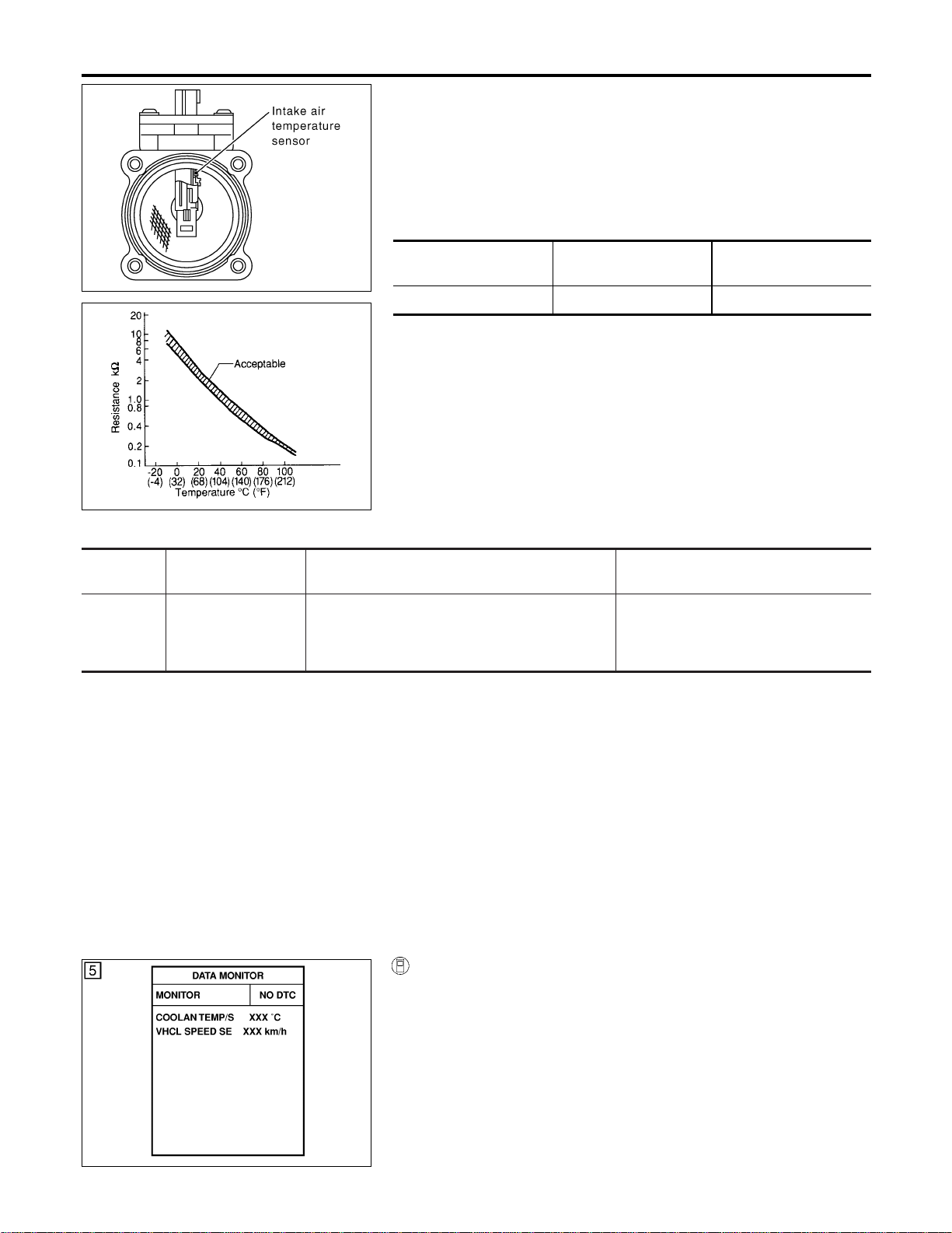
SEC266C
SEF012P
Component Description
NFEC0767
The intake air temperature sensor is mounted to the air duct hous-
ing. The sensor detects intake air temperature and transmits a sig-
nal to the ECM.
The temperature sensing unit uses a thermistor which is sensitive
to the change in temperature. Electrical resistance of the thermistor
decreases in response to the temperature rise.
<Reference data>
Intake air
temperature °C (°F)
Voltage* V Resistance kΩ
25 (77) 3.32 1.9 - 2.1
*: These data are reference values and are measured between ECM terminal 66
(Intake air temperature sensor) and body ground.
CAUTION:
Do not use ECM ground terminals when measuring input/
output voltage. Doing so may result in damage to the ECM’s
transistor. Use a ground other than ECM terminals, such as
the ground.
On Board Diagnosis Logic
NFEC0768
DTC No.
Trouble diagnosis
name
DTC Detecting Condition Possible Cause
P0127
0127
Intake air temperature
too high
Rationally incorrect voltage from the sensor is sent
to ECM, compared with the voltage signal from
engine coolant temperature sensor.
I Harness or connectors
(The sensor circuit is open or
shorted.)
I Intake air temperature sensor
DTC Confirmation Procedure
NFEC0770
NOTE:
If “DTC Confirmation Procedure” has been previously conducted,
always turn ignition switch “OFF” and wait at least 10 seconds
before conducting the next test.
CAUTION:
Always drive vehicle at a safe speed.
TESTING CONDITION:
This test may be conducted with the drive wheels lifted in the
shop or by driving the vehicle. If a road test is expected to be
easier, it is unnecessary to lift the vehicle.
SEF176Y
WITH CONSULT-II
NFEC0770S03
1) Wait until engine coolant temperature is less than 90°C
(194°F).
a) Turn ignition switch “ON”.
b) Select “DATA MONITOR” mode with CONSULT-II.
c) Check the engine coolant temperature.
d) If the engine coolant temperature is not less than 90°C
(194°F), turn ignition switch “OFF” and cool down engine.
I Perform the following steps before engine coolant temperature
is above 90°C (194°F).
2) Turn ignition switch “ON”.
DTC P0127 IAT SENSOR
Component Description
EC-216
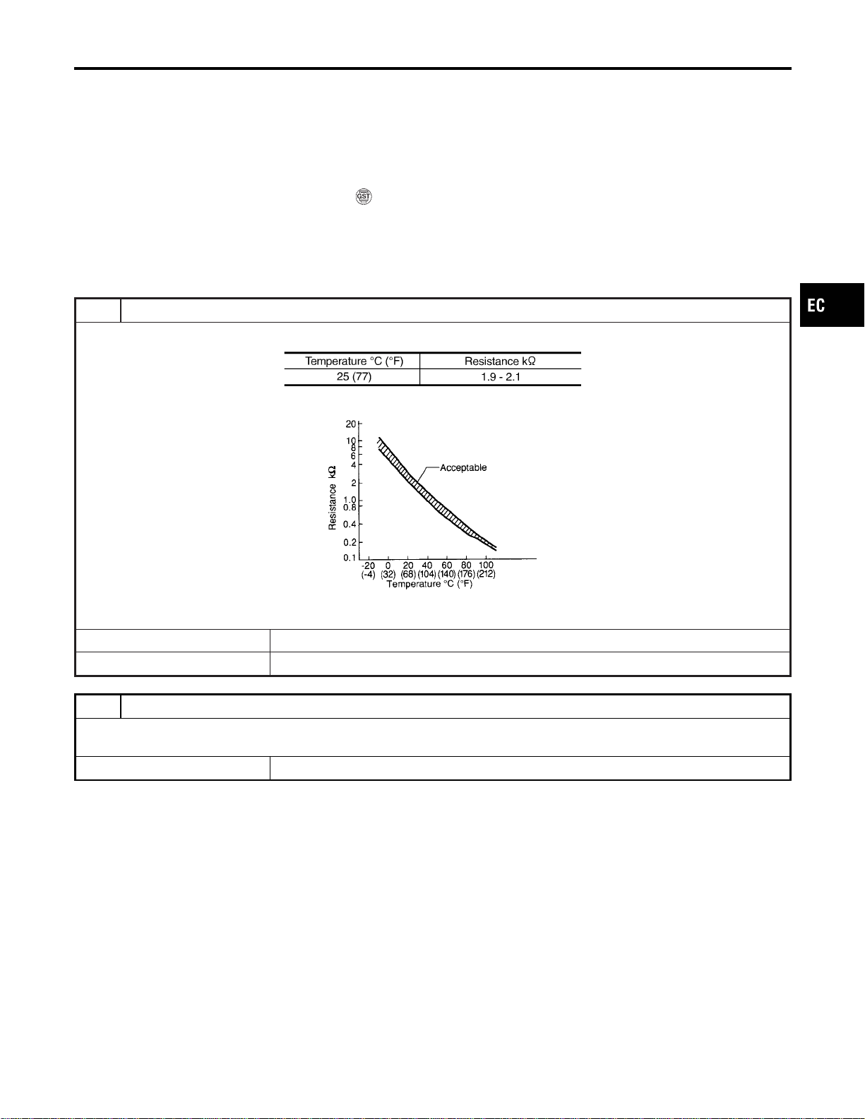
3) Select “DATA MONITOR” mode with CONSULT-II.
4) Start engine.
5) Hold vehicle speed at more than 70 km/h (43 MPH) for 100
consecutive seconds.
6) If 1st trip DTC is detected, go to “Diagnostic Procedure”,
EC-217.
WITH GST
NFEC0770S04
Follow the procedure “With CONSULT-II” above.
Diagnostic Procedure
NFEC0772
1 CHECK INTAKE AIR TEMPERATURE SENSOR
Check resistance between intake air temperature sensor terminals 3 and 5 as shown in the figure.
MTBL1143
SEF012P
OK or NG
OK © GO TO 2.
NG © Replace intake air temperature sensor.
2 CHECK INTERMITTENT INCIDENT
I Refer to “TROUBLE DIAGNOSIS FOR INTERMITTENT INCIDENT”, EC-156.
I Refer to wiring diagram, EC-204.
© INSPECTION END
GI
MA
EM
LC
FE
CL
MT
AT
AX
SU
BR
ST
RS
BT
HA
SC
EL
IDX
DTC P0127 IAT SENSOR
DTC Confirmation Procedure (Cont’d)
EC-217

On Board Diagnosis Logic
NFEC1289
Engine coolant temperature has not risen enough to open the ther-
mostat even though the engine has run long enough.
This is due to a leak in the seal or the thermostat open stuck.
DTC No.
Trouble diagnosis
name
DTC Detecting Condition Possible Cause
P0128
0128
Thermostat function The engine coolant temperature does not reach to
specified temperature even though the engine has
run long enough.
I Thermostat malfunction
I Leakage from sealing portion of ther-
mostat
I Engine coolant temperature sensor
DTC Confirmation Procedure
NFEC1291
NOTE:
If “DTC Confirmation Procedure” has been previously conducted,
always turn ignition switch “OFF” and wait at least 10 seconds
before conducting the next test.
TESTING CONDITION:
I For best results, perform at ambient temperature of –10°C
(14°F) or higher.
I For best results, perform at engine coolant temperature of
–10°C (14°F) to 60°C (140°F).
WITH CONSULT-II
NFEC1291S01
1) Replace thermostat with new one. Refer to LC-18, “Thermo-
stat”. Use only a genuine NISSAN thermostat as a replace-
ment. If an incorrect thermostat is used, the MILmay come on.
2) Turn ignition switch “ON”.
3) Select “COOLAN TEMP/S” in “DATA MONITOR” mode with
CONSULT-II.
4) Check that the “COOLAN TEMP/S” is above 60°C (140°F).
If it is below 60°C (140°F), go to following step.
If it is above 60°C (140°F), stop engine and cool down the
engine to less than 60°C (140°F), then retry from step 1.
5) Drive vehicle for 10 consecutive minutes under the following
conditions.
VHCL SPEED SE 80 - 120 km/h (50 - 75 MPH)
If 1st trip DTC is detected, go to “Diagnostic Procedure”,
EC-219.
WITH GST
NFEC1291S02
1) Follow the prodedure “WITH CONSULT-II” above.
DTC P0128 THERMOSTAT FUNCTION
On Board Diagnosis Logic
EC-218
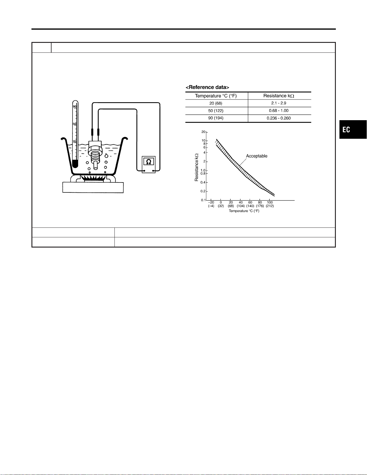
Diagnostic Procedure
NFEC1292
1 CHECK ENGINE COOLANT TEMPERATURE SENSOR
1. Turn ignition switch OFF.
2. Remove engine coolant temperature sensor.
3. Check resistance between engine coolant temperature sensor terminals under the following conditions.
SEF304X
OK or NG
OK © INSPECTION END
NG © Replace engine coolant temperature sensor.
GI
MA
EM
LC
FE
CL
MT
AT
AX
SU
BR
ST
RS
BT
HA
SC
EL
IDX
DTC P0128 THERMOSTAT FUNCTION
Diagnostic Procedure
EC-219
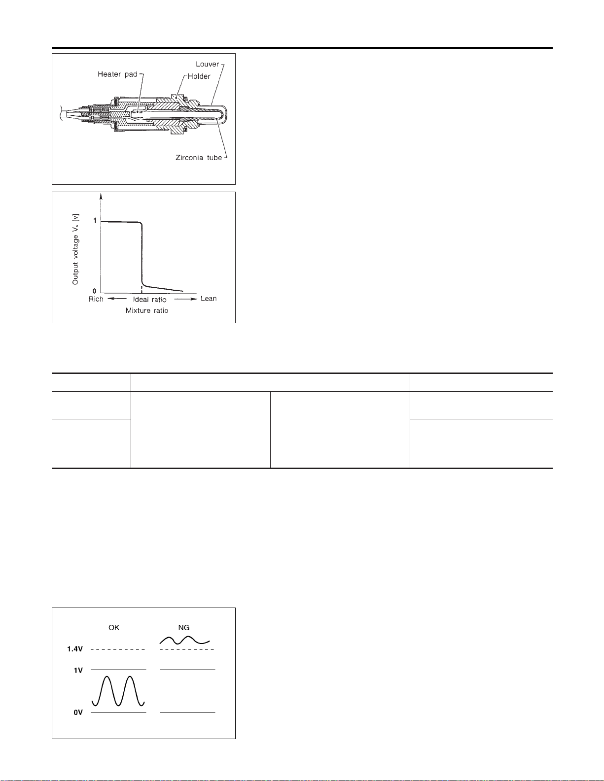
SEF463R
SEF288D
Component Description
NFEC0873
The heated oxygen sensor 1 is placed into the front tube. It detects
the amount of oxygen in the exhaust gas compared to the outside
air. The heated oxygen sensor 1 has a closed-end tube made of
ceramic zirconia. The zirconia generates voltage from approxi-
mately 1V in richer conditions to 0V in leaner conditions. The
heated oxygen sensor 1 signal is sent to the ECM. The ECM
adjusts the injection pulse duration to achieve the ideal air-fuel
ratio. The ideal air-fuel ratio occurs near the radical change from
1V to 0V.
CONSULT-II Reference Value in Data Monitor
Mode
NFEC0874
Specification data are reference values.
MONITOR ITEM CONDITION SPECIFICATION
HO2S1 (B1)
HO2S1 (B2)
I Engine: After warming up
Maintaining engine speed at 2,000
rpm
0 - 0.3V +, Approx. 0.6 - 1.0V
HO2S1 MNTR
(B1)
HO2S1 MNTR
(B2)
LEAN +, RICH
Changes more than 5 times during
10 seconds.
SEF301UA
On Board Diagnosis Logic
NFEC0876
To judge the malfunction, the diagnosis checks that the heated
oxygen sensor 1 output is not inordinately high.
DTC P0132, P0152 HO2S1
Component Description
EC-220
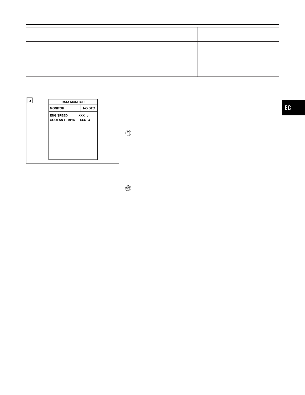
DTC No.
Trouble diagnosis
name
DTC Detecting Condition Possible Cause
P0132
0132
(Bank 1)
P0152
0152
(Bank 2)
Heated oxygen sen-
sor 1 circuit high volt-
age
An excessively high voltage from the sensor is
sent to ECM.
I Harness or connectors
(The sensor circuit is open or
shorted.)
I Heated oxygen sensor 1
SEF174Y
DTC Confirmation Procedure
NFEC0877
NOTE:
If “DTC Confirmation Procedure” has been previously conducted,
always turn ignition switch “OFF” and wait at least 10 seconds
before conducting the next test.
WITH CONSULT-II
NFEC0877S01
1) Start engine and warm it up to normal operating temperature.
2) Turn ignition switch “OFF” and wait at least 10 seconds.
3) Turn ignition switch “ON”.
4) Select “DATA MONITOR” mode with CONSULT-II.
5) Restart engine and let it idle for 25 seconds.
6) If 1st trip DTC is detected, go to “Diagnostic Procedure”,
EC-224.
WITH GST
NFEC0877S02
1) Start engine and warm it up to normal operating temperature.
2) Turn ignition switch “OFF” and wait at least 10 seconds.
3) Restart engine and let it idle for 25 seconds.
4) Turn ignition switch “OFF” and wait at least 10 seconds.
5) Restart engine and let it idle for 25 seconds.
6) Select “MODE 3” with GST.
7) If DTC is detected, go to “Diagnostic Procedure”, EC-224.
I When using GST, “DTC Confirmation Procedure” should
be performed twice as much as when using CONSULT-II
because GST cannot display MODE 7 (1st trip DTC) con-
cerning this diagnosis. Therefore, using CONSULT-II is
recommended.
GI
MA
EM
LC
FE
CL
MT
AT
AX
SU
BR
ST
RS
BT
HA
SC
EL
IDX
DTC P0132, P0152 HO2S1
On Board Diagnosis Logic (Cont’d)
EC-221
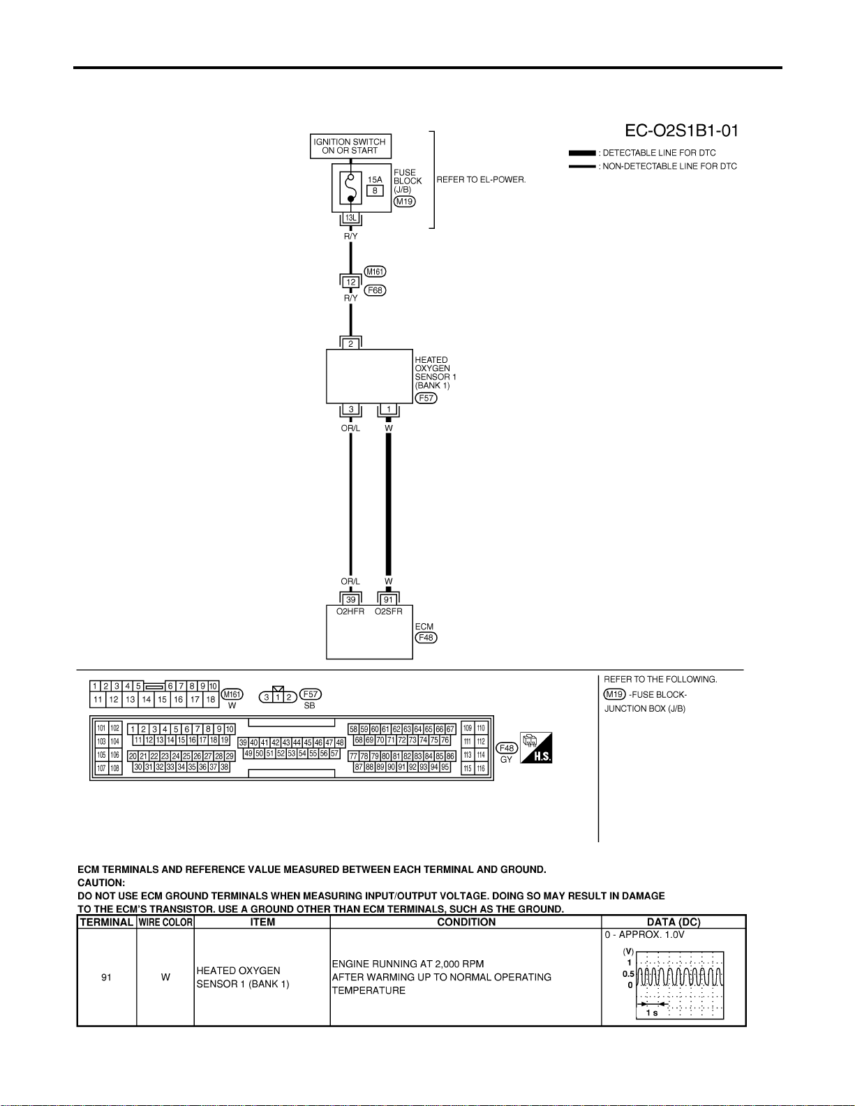
Wiring Diagram
NFEC0878
BANK 1
NFEC0878S01
MEC479D
SEC107D
DTC P0132, P0152 HO2S1
Wiring Diagram
EC-222
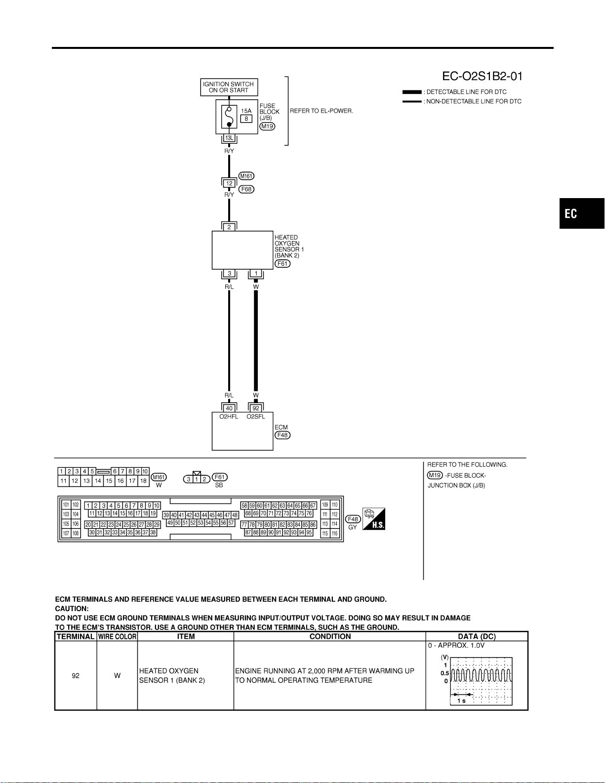
BANK 2
NFEC0878S02
MEC480D
SEC108D
GI
MA
EM
LC
FE
CL
MT
AT
AX
SU
BR
ST
RS
BT
HA
SC
EL
IDX
DTC P0132, P0152 HO2S1
Wiring Diagram (Cont’d)
EC-223
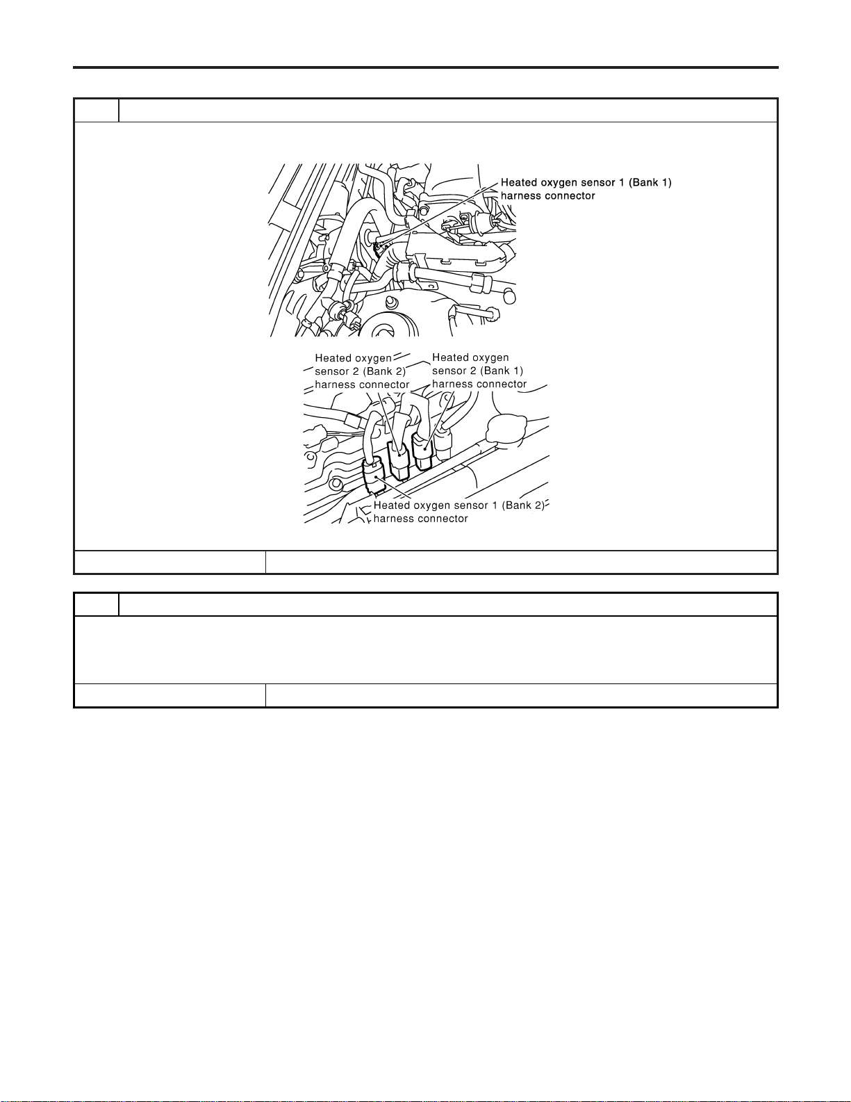
Diagnostic Procedure
NFEC0879
1 INSPECTION START
1. Turn ignition switch “OFF”.
2. Disconnect corresponding heated oxygen sensor 1 harness connector.
SEC099D
SEC134D
© GO TO 2.
2 RETIGHTEN HEATED OXYGEN SENSOR 1
Loosen and retighten corresponding heated oxygen sensor 1.
Tightening torque:
40 - 60 N·m (4.1 - 6.1 kg-m, 30 - 44 ft-lb)
© GO TO 3.
DTC P0132, P0152 HO2S1
Diagnostic Procedure
EC-224
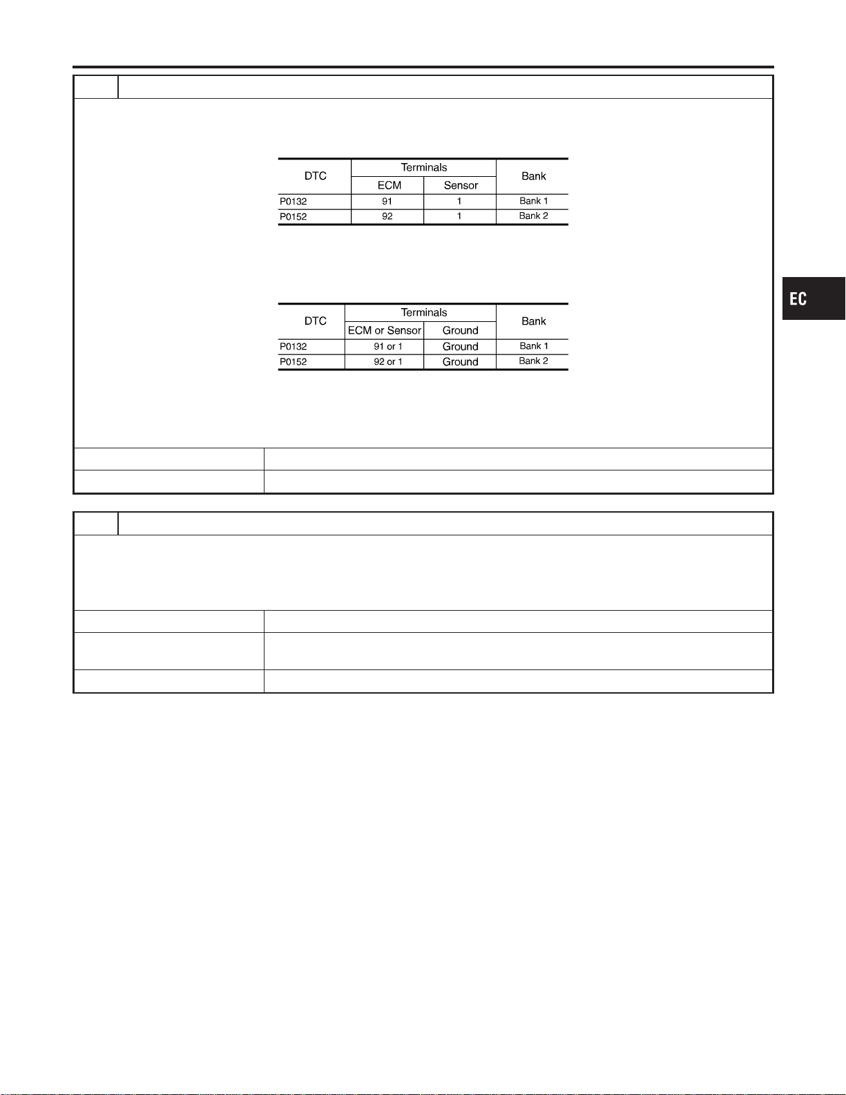
3 CHECK HO2S1 INPUT SIGNAL CIRCUIT FOR OPEN AND SHORT
1. Disconnect ECM harness connector.
2. Check harness continuity between ECM terminal and HO2S1 terminal as follows.
Refer to Wiring Diagram.
MTBL1144
Continuity should exist.
3. Check harness continuity between ECM terminal or HO2S1 terminal and ground as follows.
Refer to Wiring Diagram.
MTBL1145
Continuity should not exist.
4. Also check harness for short to power.
OK or NG
OK © GO TO 4.
NG © Repair open circuit or short to ground or short to power in harness or connectors.
4 CHECK HO2S1 CONNECTOR FOR WATER
1. Disconnect heated oxygen sensor 1 harness connector.
2. Check connectors for water.
Water should not exist.
OK or NG
OK (With CONSULT-II) © GO TO 5.
OK (Without CONSULT-
II)
© GO TO 6.
NG © Repair or replace harness or connectors.
GI
MA
EM
LC
FE
CL
MT
AT
AX
SU
BR
ST
RS
BT
HA
SC
EL
IDX
DTC P0132, P0152 HO2S1
Diagnostic Procedure (Cont’d)
EC-225
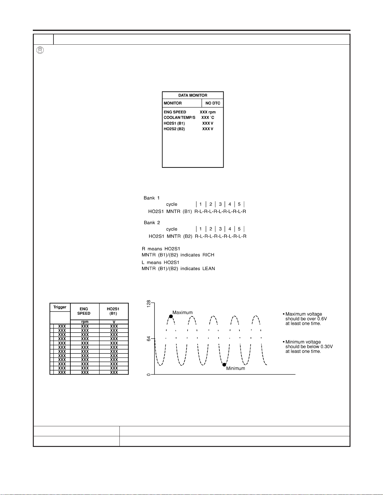
5 CHECK HEATED OXYGEN SENSOR 1
With CONSULT-II
1. Start engine and warm it up to normal operating temperature.
2. Select “MANU TRIG” and adjust “TRIGGER POINT” to 100% in “DATA MONITOR” mode with CONSULT-II.
3. Select “HO2S1 (B1)/(B2)” and “HO2S1 MNTR (B1)/(B2)”.
4. Hold engine speed at 2,000 rpm under no load during the following steps.
5. Touch “RECORD” on CONSULT-II screen.
SEF967Y
6. Check the following.
I “HO2S1 MNTR (B1)/(B2)” in “DATA MONITOR” mode changes from “RICH” to “LEAN” to “RICH” 5 times in 10 seconds.
5 times (cycles) are counted as shown left:
SEF647Y
I “HO2S1 (B1)/(B2)” voltage goes above 0.6V at least once.
I “HO2S1 (B1)/(B2)” voltage goes below 0.3V at least once.
I “HO2S1 (B1)/(B2)” voltage never exceeds 1.0V.
SEF648Y
CAUTION:
I Discard any heated oxygen sensor which has been dropped from a height of more than 0.5 m (19.7 in) onto a
hard surface such as a concrete floor; use a new one.
I Before installing new oxygen sensor, clean exhaust system threads using Oxygen Sensor Thread Cleaner tool
J-43897-18 or J-43897-12 and approved anti-seize lubricant.
OK or NG
OK © GO TO 7.
NG © Replace malfunctioning heated oxygen sensor 1.
DTC P0132, P0152 HO2S1
Diagnostic Procedure (Cont’d)
EC-226
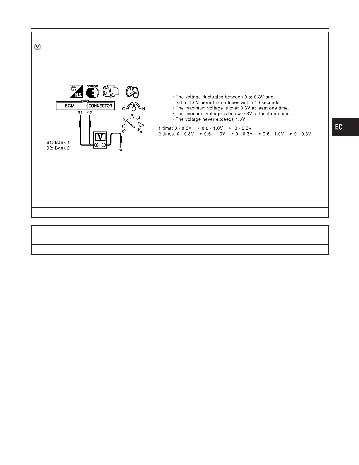
6 CHECK HEATED OXYGEN SENSOR 1
Without CONSULT-II
1. Start engine and warm it up to normal operating temperature.
2. Set voltmeter probes between ECM terminal 91 (HO2S1 bank 1 signal) or 92 (HO2S1 bank 2 signal) and engine
ground.
3. Check the following with engine speed held at 2,000 rpm constant under no load.
SEC109D
CAUTION:
I Discard any heated oxygen sensor which has been dropped from a height of more than 0.5 m (19.7 in) onto a
hard surface such as a concrete floor; use a new one.
I Before installing new oxygen sensor, clean exhaust system threads using Oxygen Sensor Thread Cleaner tool
J-43897-18 or J-43897-12 and approved anti-seize lubricant.
OK or NG
OK © GO TO 7.
NG © Replace malfunctioning heated oxygen sensor 1.
7 CHECK INTERMITTENT INCIDENT
Refer to “TROUBLE DIAGNOSIS FOR INTERMITTENT INCIDENT”, EC-156.
© INSPECTION END
GI
MA
EM
LC
FE
CL
MT
AT
AX
SU
BR
ST
RS
BT
HA
SC
EL
IDX
DTC P0132, P0152 HO2S1
Diagnostic Procedure (Cont’d)
EC-227
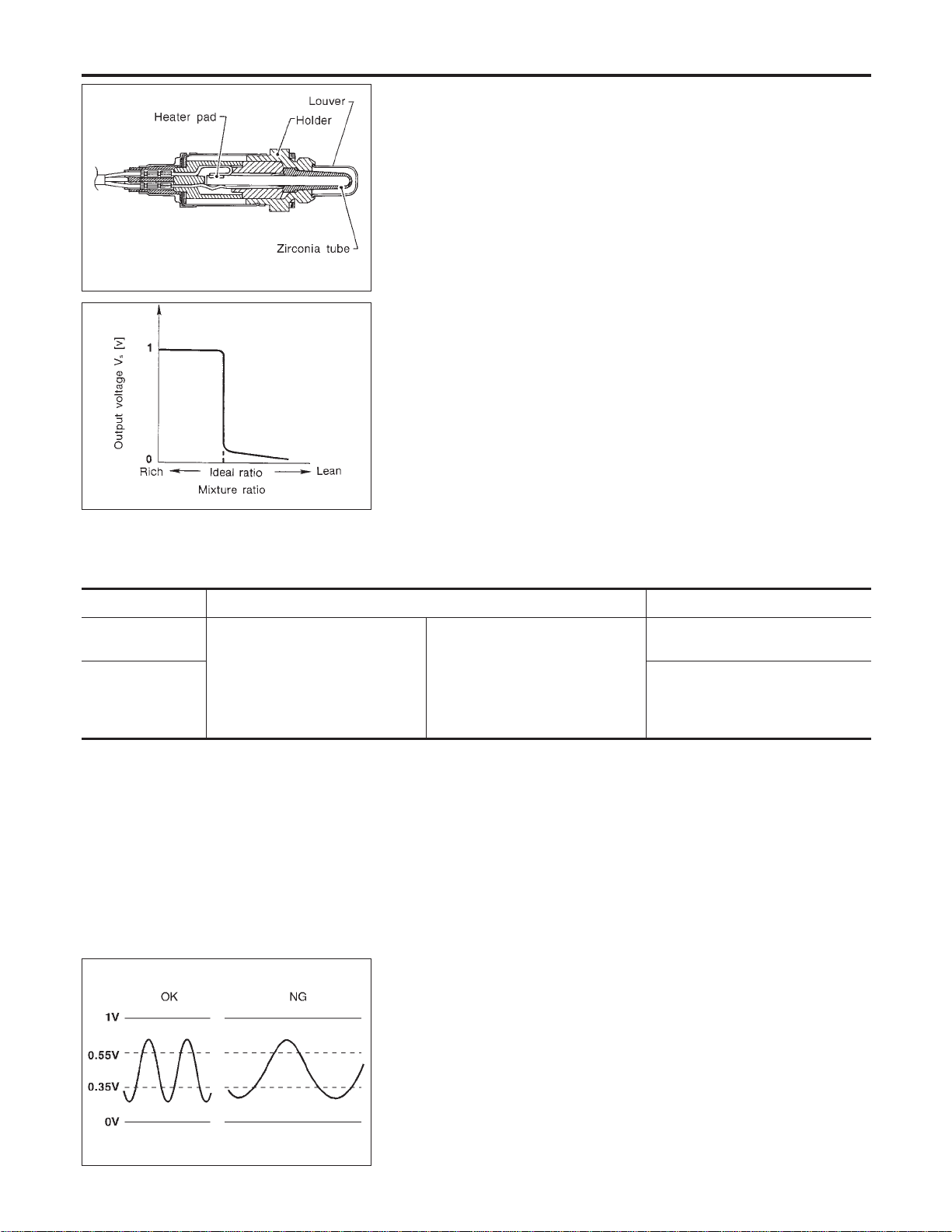
SEF463R
SEF288D
Component Description
NFEC0880
The heated oxygen sensor 1 is placed into the front tube. It detects
the amount of oxygen in the exhaust gas compared to the outside
air. The heated oxygen sensor 1 has a closed-end tube made of
ceramic zirconia. The zirconia generates voltage from approxi-
mately 1V in richer conditions to 0V in leaner conditions. The
heated oxygen sensor 1 signal is sent to the ECM. The ECM
adjusts the injection pulse duration to achieve the ideal air-fuel
ratio. The ideal air-fuel ratio occurs near the radical change from
1V to 0V.
CONSULT-II Reference Value in Data Monitor
Mode
NFEC0881
Specification data are reference values.
MONITOR ITEM CONDITION SPECIFICATION
HO2S1 (B1)
HO2S1 (B2)
I Engine: After warming up
Maintaining engine speed at 2,000
rpm
0 - 0.3V +, Approx. 0.6 - 1.0V
HO2S1 MNTR
(B1)
HO2S1 MNTR
(B2)
LEAN +, RICH
Changes more than 5 times during
10 seconds.
SEF010V
On Board Diagnosis Logic
NFEC0883
To judge the malfunction of heated oxygen sensor 1, this diagno-
sis measures response time of heated oxygen sensor 1 signal. The
time is compensated by engine operating (speed and load), fuel
feedback control constant, and heated oxygen sensor 1 tempera-
ture index. Judgment is based on whether the compensated time
[heated oxygen sensor 1 cycling time index] is inordinately long or
not.
DTC P0133, P0153 HO2S1
Component Description
EC-228
DTC No.
Trouble diagnosis
name
DTC Detecting Condition Possible Cause
P0133
0133
(Bank 1)
P0153
0153
(Bank 2)
Heated oxygen sen-
sor 1 circuit slow
response
The response of the voltage signal from the sen-
sor takes more than the specified time.
I Harness or connectors
(The sensor circuit is open or
shorted.)
I Heated oxygen sensor 1
I Heated oxygen sensor 1 heater
I Fuel pressure
I Injectors
I Intake air leaks
I Exhaust gas leaks
I PCV valve
I Mass air flow sensor
DTC Confirmation Procedure
NFEC0884
CAUTION:
Always drive vehicle at a safe speed.
NOTE:
If “DTC Confirmation Procedure” has been previously conducted,
always turn ignition switch “OFF” and wait at least 10 seconds
before conducting the next test.
TESTING CONDITION:
I Always perform at a temperature above −10°C (14°F).
I Before performing the following procedure, confirm that
battery voltage is more than 11V at idle.
GI
MA
EM
LC
FE
CL
MT
AT
AX
SU
BR
ST
RS
BT
HA
SC
EL
IDX
DTC P0133, P0153 HO2S1
On Board Diagnosis Logic (Cont’d)
EC-229
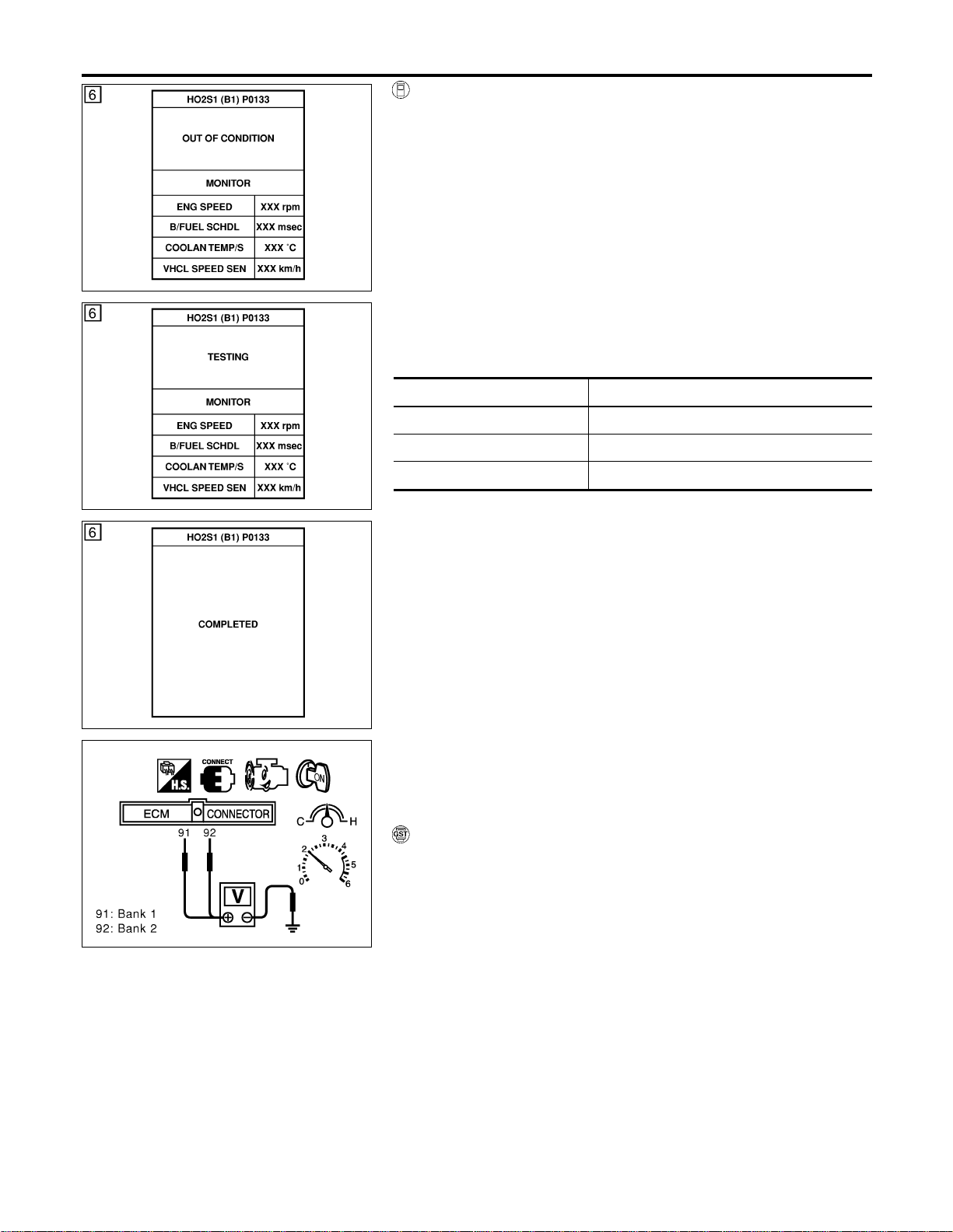
SEF338Z
SEF339Z
SEF658Y
WITH CONSULT-II
NFEC0884S01
1) Start engine and warm it up to normal operating temperature.
2) Stop engine and wait at least 5 seconds.
3) Turn ignition switch “ON” and select “HO2S1 (B1)/(B2) P0133/
P0153” of “HO2S1” in “DTC WORK SUPPORT” mode with
CONSULT-II.
4) Touch “START”.
5) Start engine and let it idle for at least 3 minutes.
NOTE:
Never raise engine speed above 3,600 rpm after this step. If
the engine speed limit is exceeded, return to step 5.
6) When the following conditions are met, “TESTING” will be dis-
played on the CONSULT-II screen. Maintain the conditions
continuously until “TESTING” changes to “COMPLETED”. (It
will take approximately 40 to 50 seconds.)
ENG SPEED 1,200 - 3,100 rpm
Vehicle speed More than 80 km/h (50 MPH)
B/FUEL SCHDL 2.5 - 12 msec
Selector lever Suitable position
If “TESTING” is not displayed after 5 minutes, retry from
step 2.
7) Make sure that “OK” is displayed after touching “SELF-DIAG
RESULTS”. If “NG” is displayed, refer to “Diagnostic
Procedure”, EC-233.
SEC902C
Overall Function Check
NFEC0885
Use this procedure to check the overall function of the heated oxy-
gen sensor 1 circuit. During this check, a 1st trip DTC might not be
confirmed.
WITH GST
NFEC0885S01
1) Start engine and warm it up to normal operating temperature.
2) Set voltmeter probes between ECM terminal 91 (HO2S1 bank
1 signal) or 92 (HO2S1 bank 2 signal) and engine ground.
3) Check the following with engine speed held at 2,000 rpm con-
stant under no load.
I The voltage fluctuates between 0 to 0.3V and 0.6 to 1.0V more
than 5 times within 10 seconds.
1 time: 0 - 0.3V → 0.6 - 1.0V → 0 - 0.3V
2 times: 0 - 0.3V → 0.6 - 1.0V → 0 - 0.3V → 0.6 - 1.0V → 0
- 0.3V
4) If NG, go to “Diagnostic Procedure”, EC-233.
DTC P0133, P0153 HO2S1
DTC Confirmation Procedure (Cont’d)
EC-230
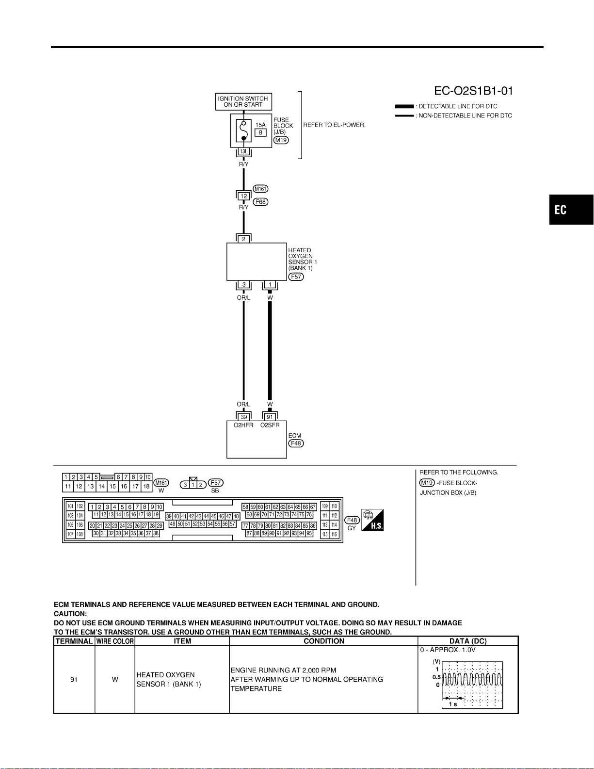
Wiring Diagram
NFEC0886
BANK 1
NFEC0886S01
MEC479D
SEC107D
GI
MA
EM
LC
FE
CL
MT
AT
AX
SU
BR
ST
RS
BT
HA
SC
EL
IDX
DTC P0133, P0153 HO2S1
Wiring Diagram
EC-231
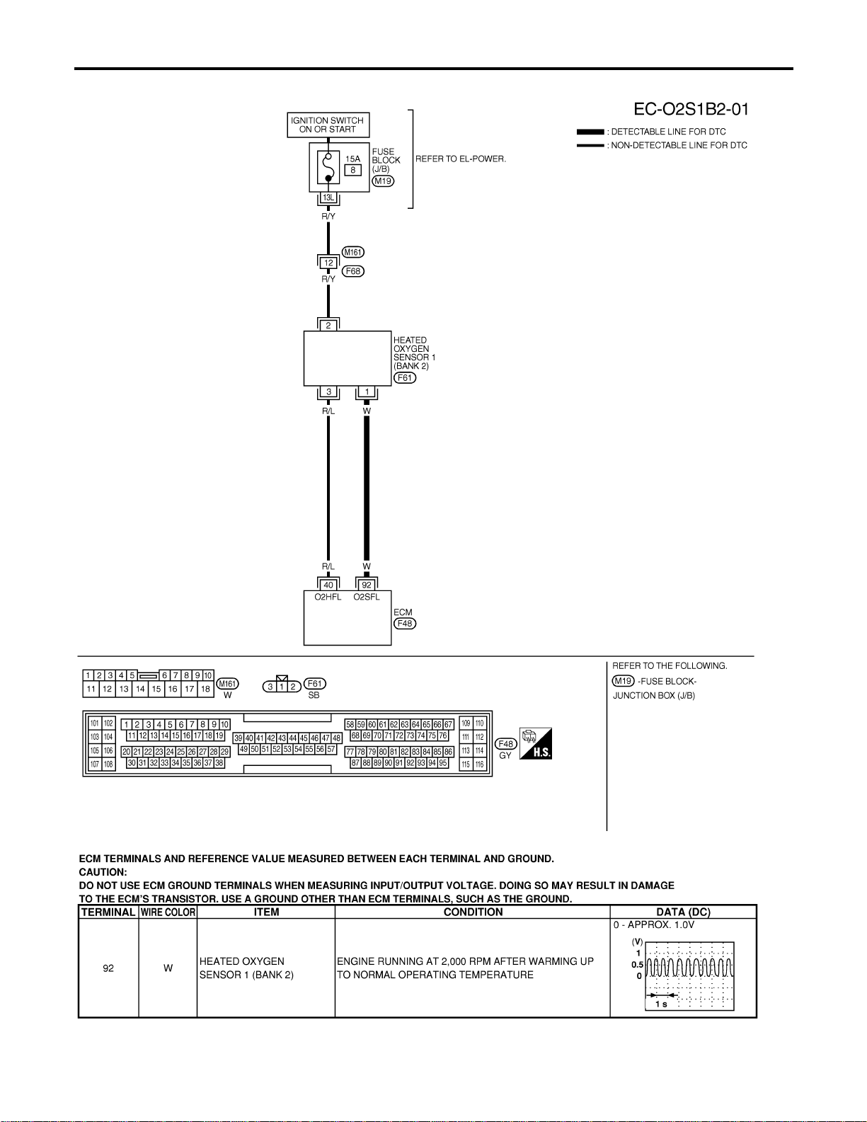
BANK 2
NFEC0886S02
MEC480D
SEC108D
DTC P0133, P0153 HO2S1
Wiring Diagram (Cont’d)
EC-232
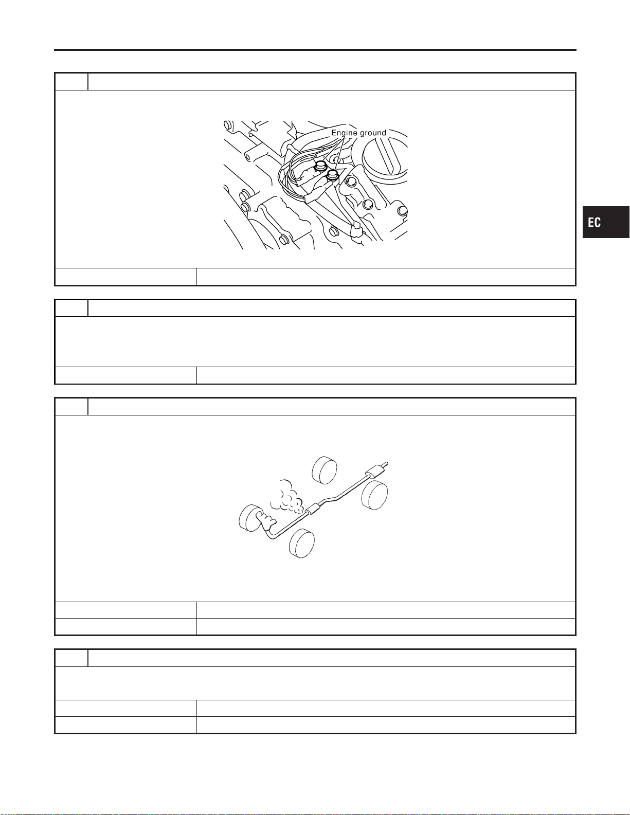
Diagnostic Procedure
NFEC0887
1 RETIGHTEN GROUND SCREWS
1. Turn ignition switch “OFF”.
2. Loosen and retighten engine ground screws.
SEC047D
© GO TO 2.
2 RETIGHTEN HEATED OXYGEN SENSOR 1
Loosen and retighten corresponding heated oxygen sensor 1.
Tightening torque:
40 - 60 N·m (4.1 - 6.1 kg-m, 30 - 44 ft-lb)
© GO TO 3.
3 CHECK FOR EXHAUST AIR LEAK
1. Start engine and run it at idle.
2. Listen for an exhaust air leak before three way catalyst.
SEF099P
OK or NG
OK © GO TO 4.
NG © Repair or replace.
4 CHECK FOR INTAKE AIR LEAK
Listen for an intake air leak after the mass air flow sensor.
OK or NG
OK © GO TO 5.
NG © Repair or replace.
GI
MA
EM
LC
FE
CL
MT
AT
AX
SU
BR
ST
RS
BT
HA
SC
EL
IDX
DTC P0133, P0153 HO2S1
Diagnostic Procedure
EC-233
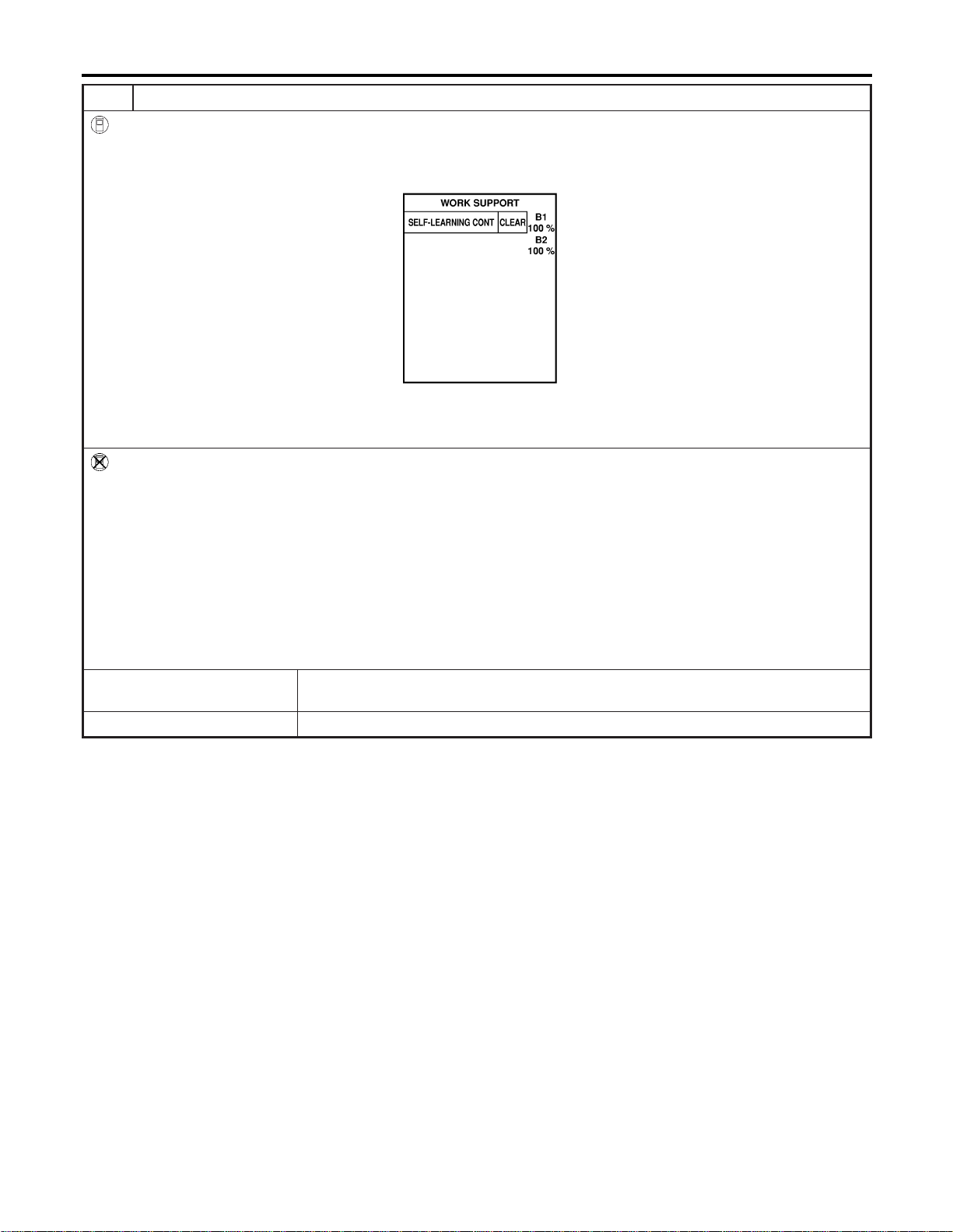
5 CLEAR THE SELF-LEARNING DATA
With CONSULT-II
1. Start engine and warm it up to normal operating temperature.
2. Select “SELF-LEARNING CONT” in “WORK SUPPORT” mode with CONSULT-II.
3. Clear the self-learning control coefficient by touching “CLEAR”.
SEF968Y
4. Run engine for at least 10 minutes at idle speed.
Is the 1st trip DTC P0171, P0172, P0174 or P0175 detected?
Is it difficult to start engine?
Without CONSULT-II
1. Start engine and warm it up to normal operating temperature.
2. Turn ignition switch “OFF”.
3. Disconnect mass air flow sensor harness connector, and restart and run engine for at least 5 seconds at idle speed.
4. Stop engine and reconnect mass air flow sensor harness connector.
5. Make sure DTC P0102 is displayed.
6. Erase the DTC memory. Refer to “HOW TO ERASE EMISSION-RELATED DIAGNOSTIC INFORMATION”, EC-91.
7. Make sure DTC P0000 is displayed.
8. Run engine for at least 10 minutes at idle speed.
Is the 1st trip DTC P0171, P0172, P0174 or P0175 detected?
Is it difficult to start engine?
YesorNo
Yes © Perform trouble diagnosis for DTC P0171, P0174 or P0172, P0175. Refer to EC-267,
EC-275.
No © GO TO 6.
DTC P0133, P0153 HO2S1
Diagnostic Procedure (Cont’d)
EC-234
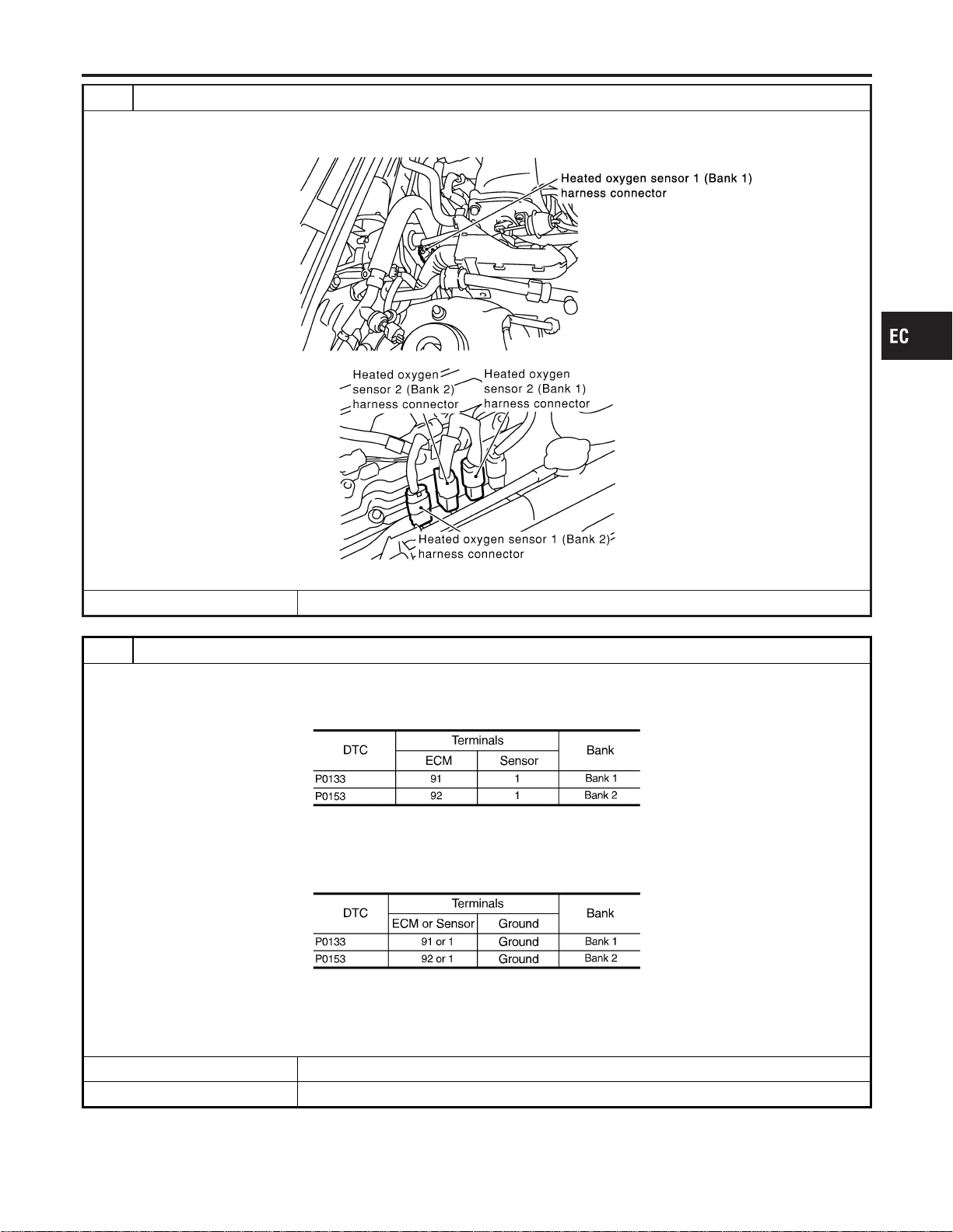
6 DISCONNECT HO2S1 HARNESS CONNECTOR
1. Turn ignition switch “OFF”.
2. Disconnect corresponding heated oxygen sensor 1 harness connector.
SEC099D
SEC134D
© GO TO 7.
7 CHECK HO2S1 INPUT SIGNAL CIRCUIT FOR OPEN AND SHORT
1. Disconnect ECM harness connector.
2. Check harness continuity between ECM terminal and HO2S1 terminal as follows.
Refer to Wiring Diagram.
MTBL1146
Continuity should exist.
3. Check harness continuity between ECM terminal or HO2S1 terminal and ground as follows.
Refer to Wiring Diagram.
MTBL1147
Continuity should not exist.
4. Also check harness for short to power.
OK or NG
OK © GO TO 8.
NG © Repair open circuit or short to ground or short to power in harness or connectors.
GI
MA
EM
LC
FE
CL
MT
AT
AX
SU
BR
ST
RS
BT
HA
SC
EL
IDX
DTC P0133, P0153 HO2S1
Diagnostic Procedure (Cont’d)
EC-235
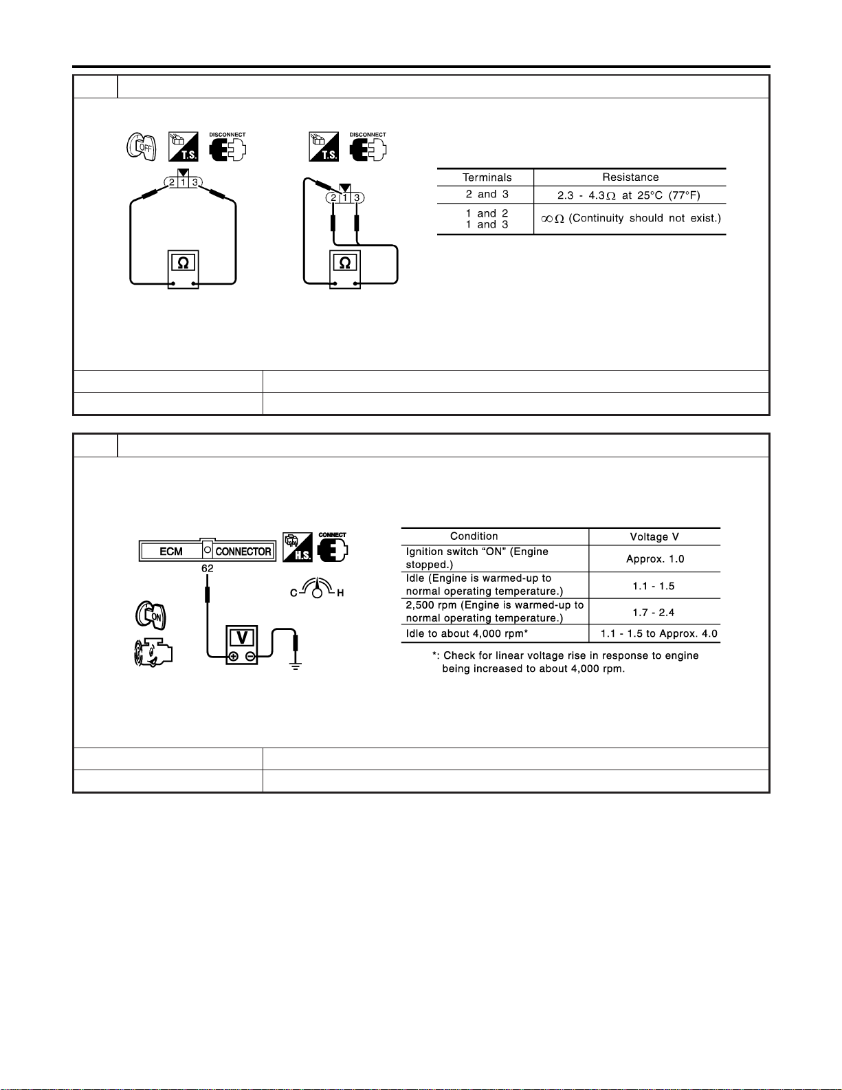
8 CHECK HEATED OXYGEN SENSOR 1 HEATER
Check resistance between HO2S1 terminals as follows.
SEF310X
CAUTION:
Discard any heated oxygen sensor which has been dropped from a height of more than 0.5 m (19.7 in) onto a
hard surface such as a concrete floor; use a new one.
OK or NG
OK © GO TO 9.
NG © GO TO 13.
9 CHECK MASS AIR FLOW SENSOR
1. Reconnect harness connectors disconnected.
2. Start engine and warm it up to normal operating temperature.
3. Check voltage between ECM terminal 62 (Mass air flow sensor signal) and ground.
SEC103D
4. If the voltage is out of specification, disconnect mass air flow sensor harness connector and connect it again.
Then repeat above check.
OK or NG
OK © GO TO 10.
NG © Replace mass air flow sensor.
DTC P0133, P0153 HO2S1
Diagnostic Procedure (Cont’d)
EC-236
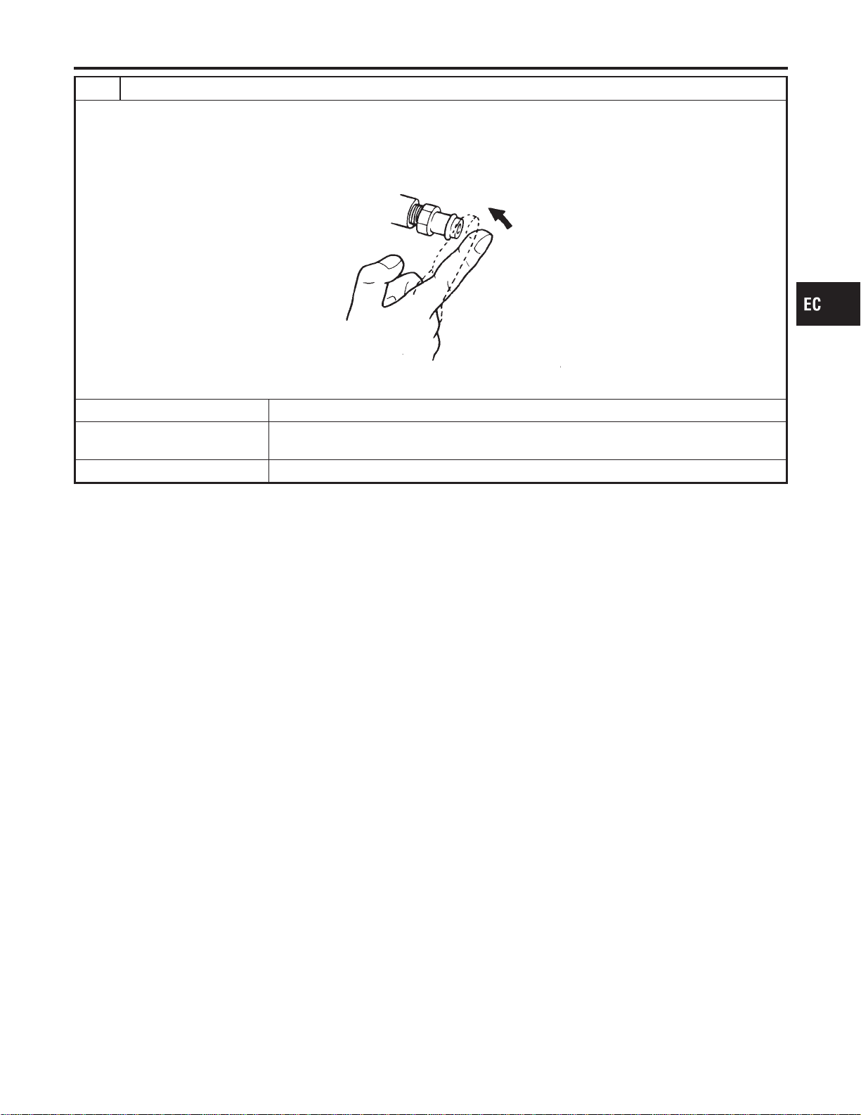
10 CHECK PCV VALVE
1. Install all removed parts.
2. Start engine and let it idle.
3. Remove PCV valve from rocker cover.
4. Make sure that a hissing noise will be heard as air passes through it and a strong vacuum should be felt immediately
when a finger is placed over valve inlet.
SEC137A
OK or NG
OK (With CONSULT-II) © GO TO 11.
OK (Without CONSULT-
II)
© GO TO 12.
NG © Replace PCV valve.
GI
MA
EM
LC
FE
CL
MT
AT
AX
SU
BR
ST
RS
BT
HA
SC
EL
IDX
DTC P0133, P0153 HO2S1
Diagnostic Procedure (Cont’d)
EC-237
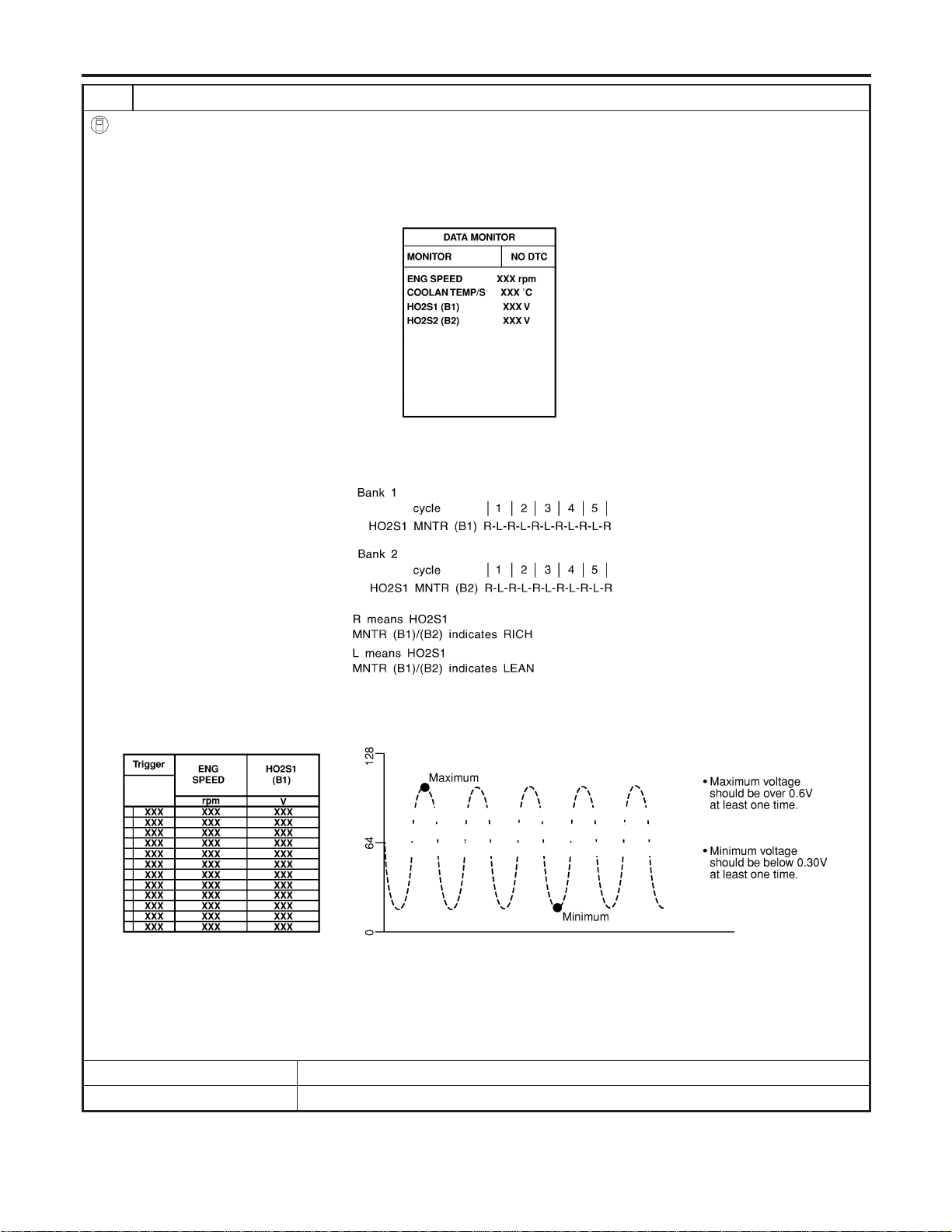
11 CHECK HEATED OXYGEN SENSOR 1
With CONSULT-II
1. Start engine and warm it up to normal operating temperature.
2. Select “MANU TRIG” and adjust “TRIGGER POINT” to 100% in “DATA MONITOR” mode with CONSULT-II.
3. Select “HO2S1 (B1)/(B2)” and “HO2S1 MNTR (B1)/(B2)”.
4. Hold engine speed at 2,000 rpm under no load during the following steps.
5. Touch “RECORD” on CONSULT-II screen.
SEF967Y
6. Check the following.
I “HO2S1 MNTR (B1)/(B2)” in “DATA MONITOR” mode changes from “RICH” to “LEAN” to “RICH” 5 times in 10 seconds.
5 times (cycles) are counted as shown below.
SEF647Y
I “HO2S1 (B1)/(B2)” voltage goes above 0.6V at least once.
I “HO2S1 (B1)/(B2)” voltage goes below 0.3V at least once.
I “HO2S1 (B1)/(B2)” voltage never exceeds 1.0V.
SEF648Y
CAUTION:
I Discard any heated oxygen sensor which has been dropped from a height of more than 0.5 m (19.7 in) onto a
hard surface such as a concrete floor; use a new one.
I Before installing new oxygen sensor, clean exhaust system threads using Oxygen Sensor Thread Cleaner tool
J-43897-18 or J-43897-12 and approved anti-seize lubricant.
OK or NG
OK © GO TO 13.
NG © Replace malfunctioning heated oxygen sensor 1.
DTC P0133, P0153 HO2S1
Diagnostic Procedure (Cont’d)
EC-238
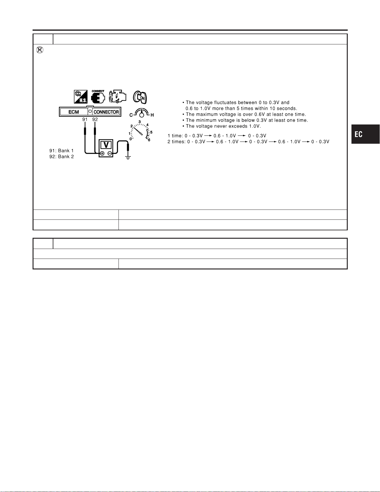
12 CHECK HEATED OXYGEN SENSOR 1
Without CONSULT-II
1. Start engine and warm it up to normal operating temperature.
2. Set voltmeter probes between ECM terminal 91 (HO2S1 bank 1 signal) or 92 (HO2S1 bank 2 signal) and engine
ground.
3. Check the following with engine speed held at 2,000 rpm constant under no load.
SEC109D
CAUTION:
I Discard any heated oxygen sensor which has been dropped from a height of more than 0.5 m (19.7 in) onto a
hard surface such as a concrete floor; use a new one.
I Before installing new oxygen sensor, clean exhaust system threads using Oxygen Sensor Thread Cleaner tool
J-43897-18 or J-43897-12 and approved anti-seize lubricant.
OK or NG
OK © GO TO 13.
NG © Replace malfunctioning heated oxygen sensor 1.
13 CHECK INTERMITTENT INCIDENT
Refer to “TROUBLE DIAGNOSIS FOR INTERMITTENT INCIDENT”, EC-156.
© INSPECTION END
GI
MA
EM
LC
FE
CL
MT
AT
AX
SU
BR
ST
RS
BT
HA
SC
EL
IDX
DTC P0133, P0153 HO2S1
Diagnostic Procedure (Cont’d)
EC-239
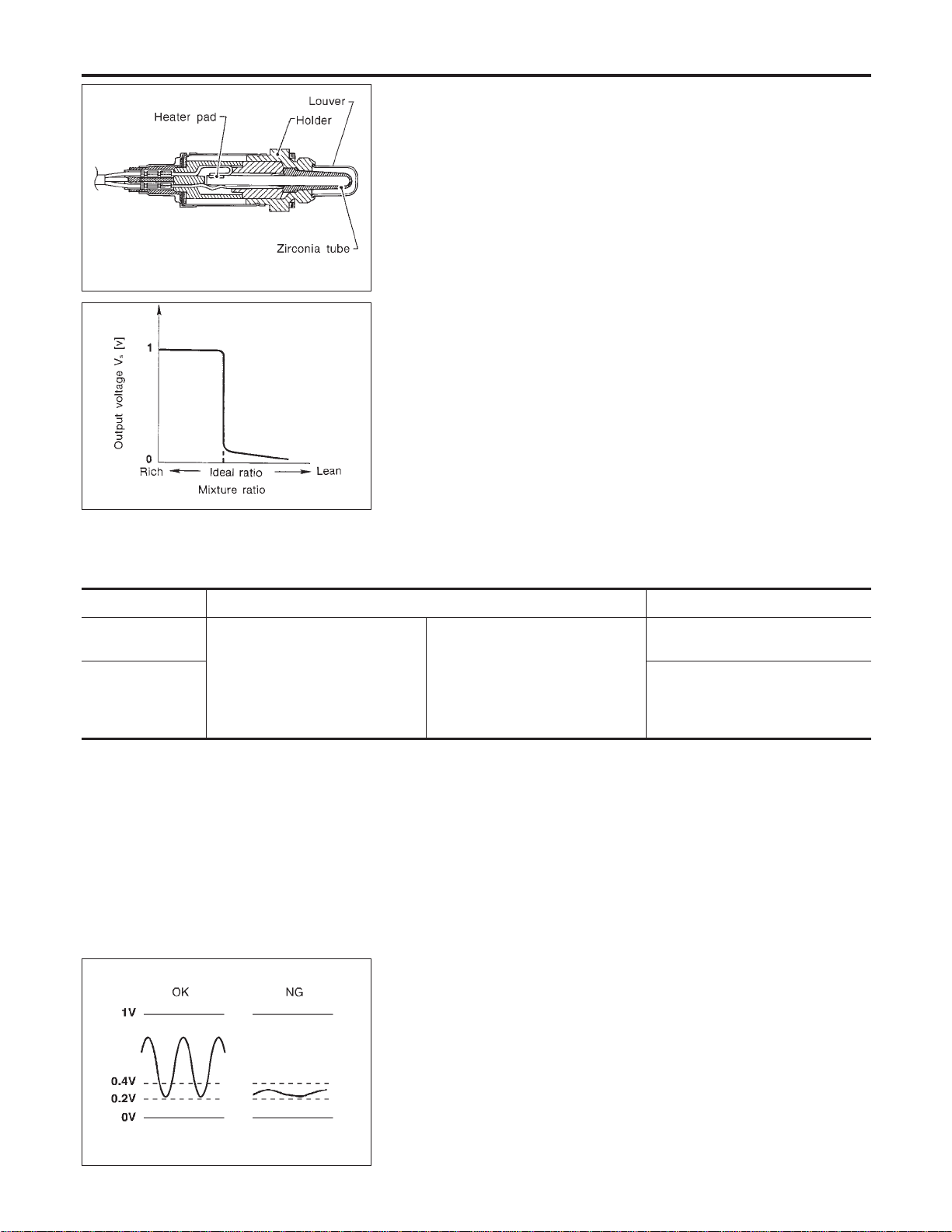
SEF463R
SEF288D
Component Description
NFEC0888
The heated oxygen sensor 1 is placed into the front tube. It detects
the amount of oxygen in the exhaust gas compared to the outside
air. The heated oxygen sensor 1 has a closed-end tube made of
ceramic zirconia. The zirconia generates voltage from approxi-
mately 1V in richer conditions to 0V in leaner conditions. The
heated oxygen sensor 1 signal is sent to the ECM. The ECM
adjusts the injection pulse duration to achieve the ideal air-fuel
ratio. The ideal air-fuel ratio occurs near the radical change from
1V to 0V.
CONSULT-II Reference Value in Data Monitor
Mode
NFEC0889
Specification data are reference values.
MONITOR ITEM CONDITION SPECIFICATION
HO2S1 (B1)
HO2S1 (B2)
I Engine: After warming up
Maintaining engine speed at 2,000
rpm
0 - 0.3V +, Approx. 0.6 - 1.0V
HO2S1 MNTR
(B1)
HO2S1 MNTR
(B2)
LEAN +, RICH
Changes more than 5 times during
10 seconds.
SEF237U
On Board Diagnosis Logic
NFEC0891
Under the condition in which the heated oxygen sensor 1 signal is
not input, the ECM circuits will read a continuous approximately
0.3V. Therefore, for this diagnosis, the time that output voltage is
within 200 to 400 mV range is monitored, and the diagnosis checks
that this time is not inordinately long.
DTC P0134, P0154 HO2S1
Component Description
EC-240
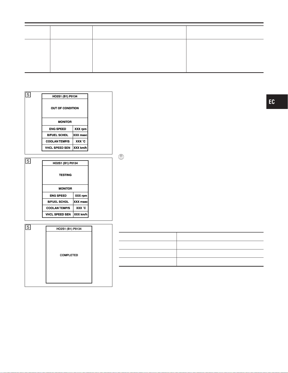
DTC No.
Trouble diagnosis
name
DTC Detecting Condition Possible Cause
P0134
0134
(Bank 1)
P0154
0154
(Bank 2)
Heated oxygen sen-
sor 1 circuit no activ-
ity detected
The voltage from the sensor is constantly approx.
0.3V.
I Harness or connectors
(The sensor circuit is open or
shorted.)
I Heated oxygen sensor 1
PBIB0544E
PBIB0545E
SEC750C
DTC Confirmation Procedure
NFEC1433
CAUTION:
Always drive vehicle at a safe speed.
NOTE:
If “DTC Confirmation Procedure” has been previously conducted,
always turn ignition switch “OFF” and wait at least 10 seconds
before conducting the next test.
TESTING CONDITION:
Before performing the following procedure, confirm that bat-
tery voltage is more than 11V at idle.
WITH CONSULT-II
NFEC1433S01
1) Start engine and warm it up to normal operating temperature.
2) Select “HO2S1 (B1)/(B2) P0134/P0154” of “HO2S1” in “DTC
WORK SUPPORT” mode with CONSULT-II.
3) Touch “START”.
4) Let it idle for at least 3 minutes.
NOTE:
Never raise engine speed above 3,600 rpm after this step. If
the engine speed limit is exceeded, return to step 4.
5) When the following conditions are met, “TESTING” will be dis-
played on the CONSULT-II screen. Maintain the conditions
continuously until “TESTING” changes to “COMPLETED”. (It
will take approximately 10 to 60 seconds.)
ENG SPEED 1,400 - 2,600 rpm
Vehicle speed More than 70 km/h (43 MPH)
B/FUEL SCHDL 2 - 12 msec
Selector lever Suitable position
If “TESTING” is not displayed after 5 minutes, retry from
step 2.
6) Make sure that “OK” is displayed after touching “SELF-DIAG
RESULTS”. If “NG” is displayed, refer to “Diagnostic
Procedure”, EC-245.
During this test, P1148 and P1168 may be stored in ECM.
GI
MA
EM
LC
FE
CL
MT
AT
AX
SU
BR
ST
RS
BT
HA
SC
EL
IDX
DTC P0134, P0154 HO2S1
On Board Diagnosis Logic (Cont’d)
EC-241
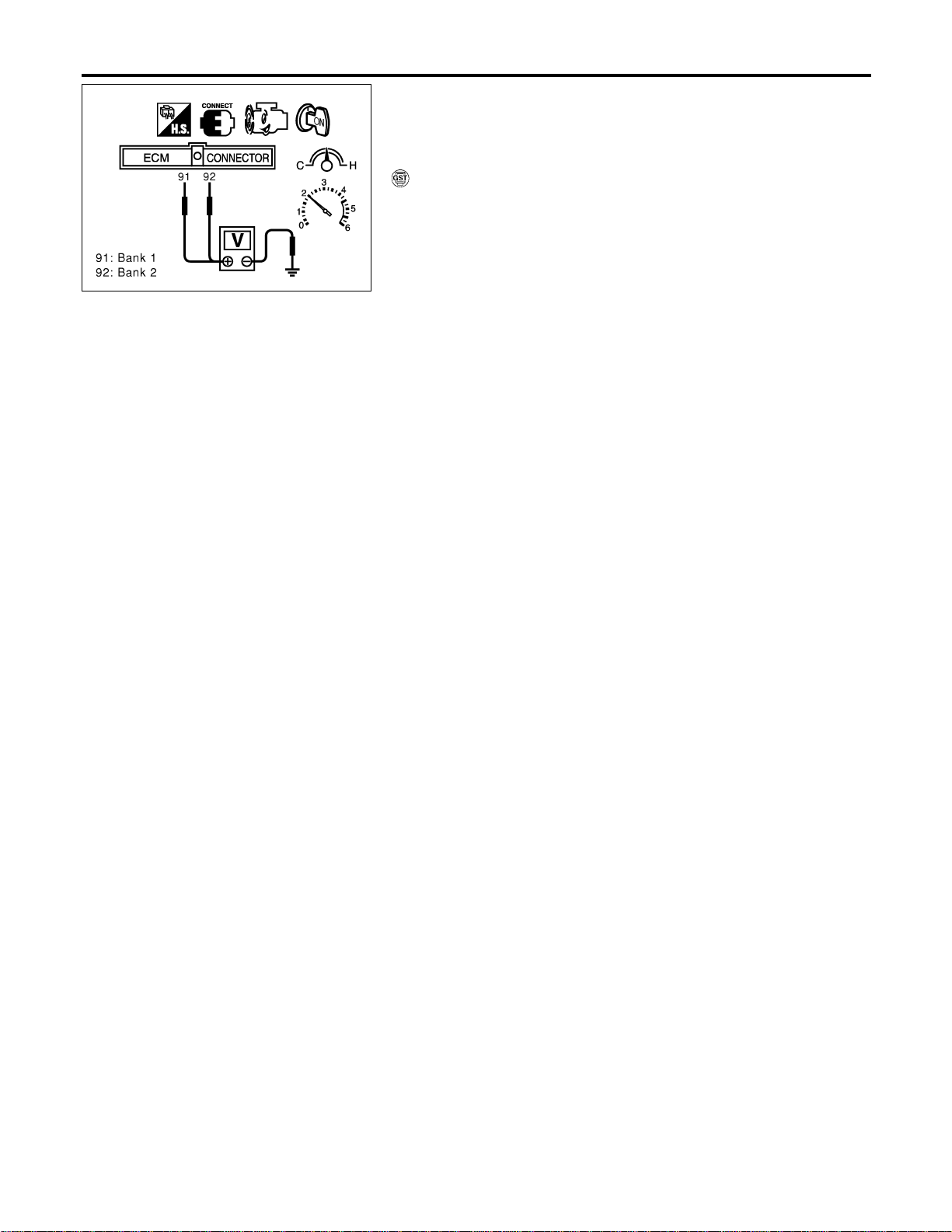
SEC902C
Overall Function Check
NFEC0893
Use this procedure to check the overall function of the heated oxy-
gen sensor 1 circuit. During this check, a 1st trip DTC might not be
confirmed.
WITH GST
NFEC0893S01
1) Start engine and warm it up to normal operating temperature.
2) Set voltmeter probes between ECM terminal 91 (HO2S1 bank
1 signal) or 92 (HO2S1 bank 2 signal) and engine ground.
3) Check the following with engine speed held at 2,000 rpm con-
stant under no load.
I The voltage does not remain in the range of 0.2 - 0.4V.
4) If NG, go to “Diagnostic Procedure”, EC-245.
DTC P0134, P0154 HO2S1
Overall Function Check
EC-242
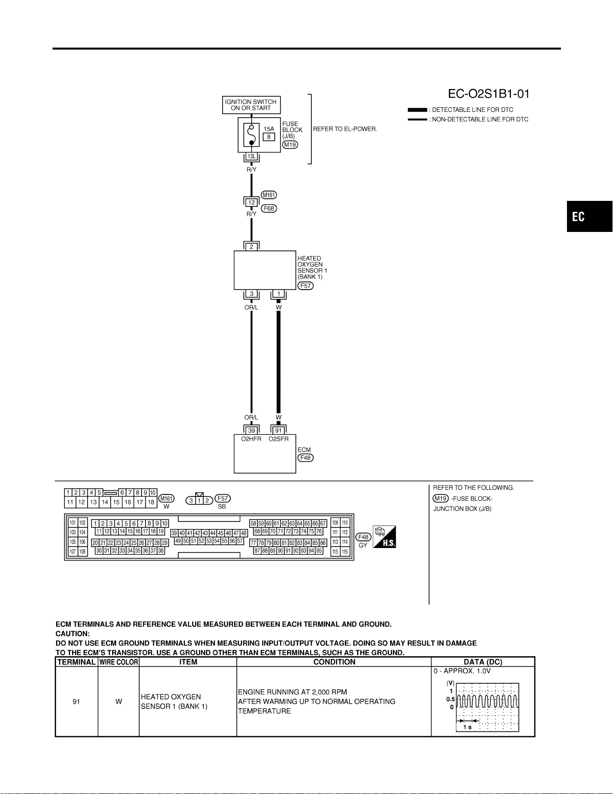
Wiring Diagram
=NFEC0894
BANK 1
NFEC0894S01
MEC479D
SEC107D
GI
MA
EM
LC
FE
CL
MT
AT
AX
SU
BR
ST
RS
BT
HA
SC
EL
IDX
DTC P0134, P0154 HO2S1
Wiring Diagram
EC-243
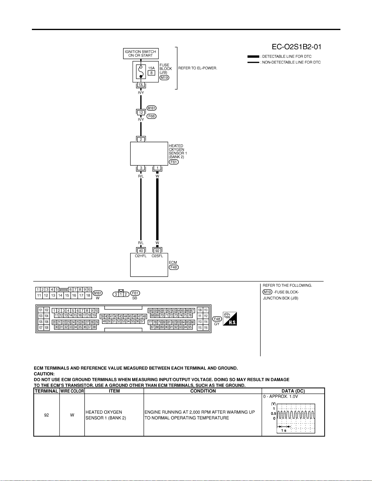
BANK 2
NFEC0894S02
MEC480D
SEC108D
DTC P0134, P0154 HO2S1
Wiring Diagram (Cont’d)
EC-244
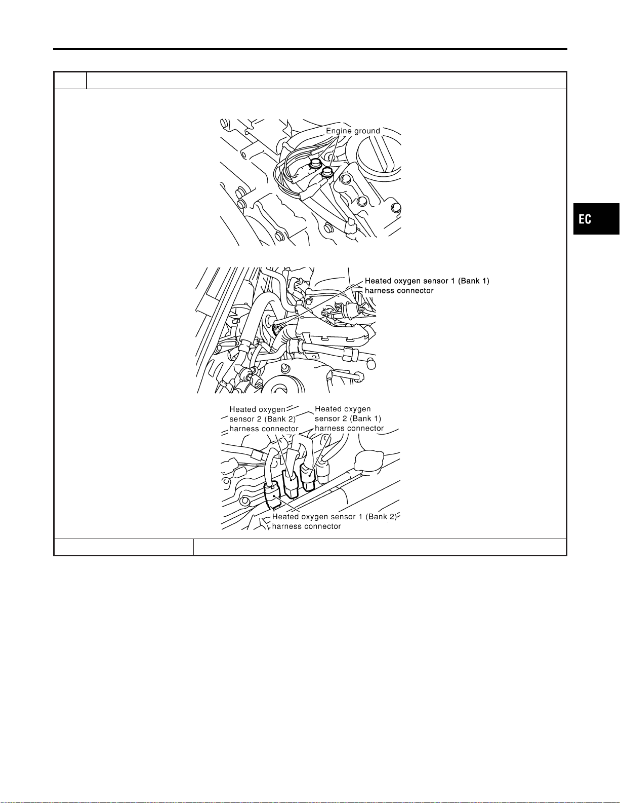
Diagnostic Procedure
NFEC0895
1 INSPECTION START
1. Turn ignition switch “OFF”.
2. Loosen and retighten engine ground screws.
SEC047D
3. Disconnect corresponding heated oxygen sensor 1 harness connector.
SEC099D
SEC134D
© GO TO 2.
GI
MA
EM
LC
FE
CL
MT
AT
AX
SU
BR
ST
RS
BT
HA
SC
EL
IDX
DTC P0134, P0154 HO2S1
Diagnostic Procedure
EC-245
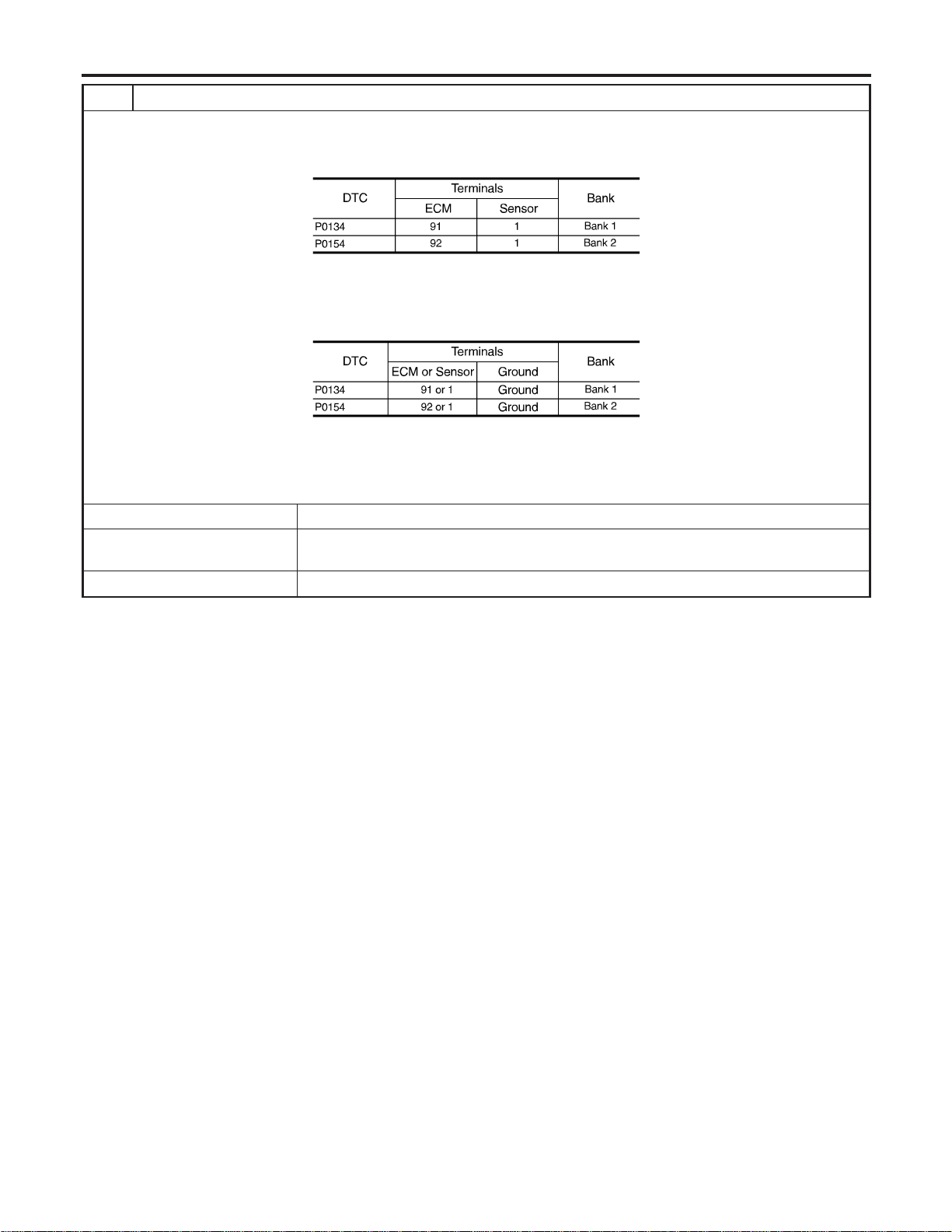
2 CHECK HO2S1 INPUT SIGNAL CIRCUIT FOR OPEN AND SHORT
1. Disconnect ECM harness connector.
2. Check harness continuity between ECM terminal and HO2S1 terminal as follows.
Refer to Wiring Diagram.
MTBL1148
Continuity should exist.
3. Check harness continuity between ECM terminal or HO2S1 terminal and ground as follows.
Refer to Wiring Diagram.
MTBL1149
Continuity should not exist.
4. Also check harness for short to power.
OK or NG
OK (With CONSULT-II) © GO TO 3.
OK (Without CONSULT-
II)
© GO TO 4.
NG © Repair open circuit or short to ground or short to power in harness or connectors.
DTC P0134, P0154 HO2S1
Diagnostic Procedure (Cont’d)
EC-246
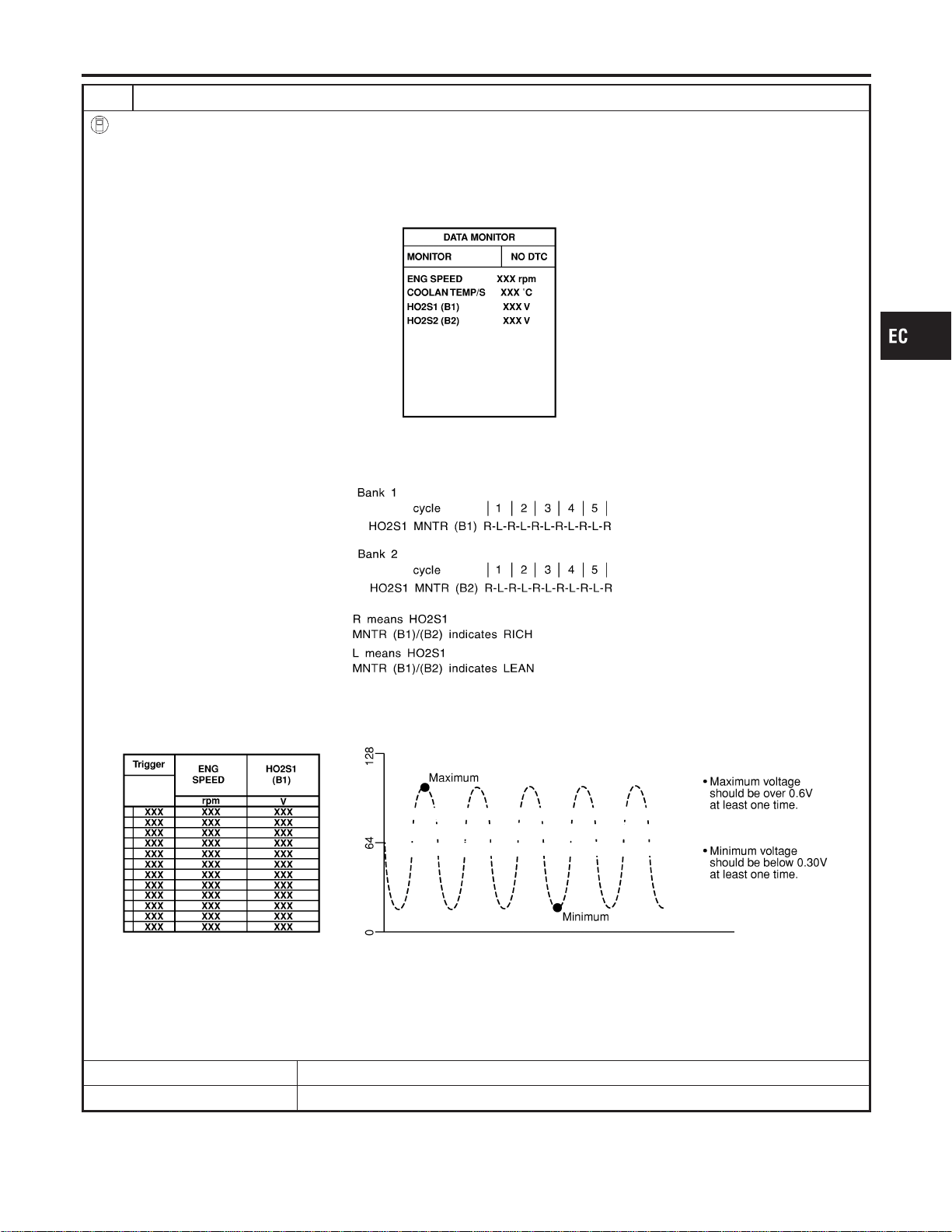
3 CHECK HEATED OXYGEN SENSOR 1
With CONSULT-II
1. Start engine and warm it up to normal operating temperature.
2. Select “MANU TRIG” and adjust “TRIGGER POINT” to 100% in “DATA MONITOR” mode with CONSULT-II.
3. Select “HO2S1 (B1)/(B2)” and “HO2S1 MNTR (B1)/(B2)”.
4. Hold engine speed at 2,000 rpm under no load during the following steps.
5. Touch “RECORD” on CONSULT-II screen.
SEF967Y
6. Check the following.
I “HO2S1 MNTR (B1)/(B2)” in “DATA MONITOR” mode changes from “RICH” to “LEAN” to “RICH” 5 times in 10 seconds.
5 times (cycles) are counted as shown below.
SEF647Y
I “HO2S1 (B1)/(B2)” voltage goes above 0.6V at least once.
I “HO2S1 (B1)/(B2)” voltage goes below 0.3V at least once.
I “HO2S1 (B1)/(B2)” voltage never exceeds 1.0V.
SEF648Y
CAUTION:
I Discard any heated oxygen sensor which has been dropped from a height of more than 0.5 m (19.7 in) onto a
hard surface such as a concrete floor; use a new one.
I Before installing new oxygen sensor, clean exhaust system threads using Oxygen Sensor Thread Cleaner tool
J-43897-18 or J-43897-12 and approved anti-seize lubricant.
OK or NG
OK © GO TO 5.
NG © Replace malfunctioning heated oxygen sensor 1.
GI
MA
EM
LC
FE
CL
MT
AT
AX
SU
BR
ST
RS
BT
HA
SC
EL
IDX
DTC P0134, P0154 HO2S1
Diagnostic Procedure (Cont’d)
EC-247
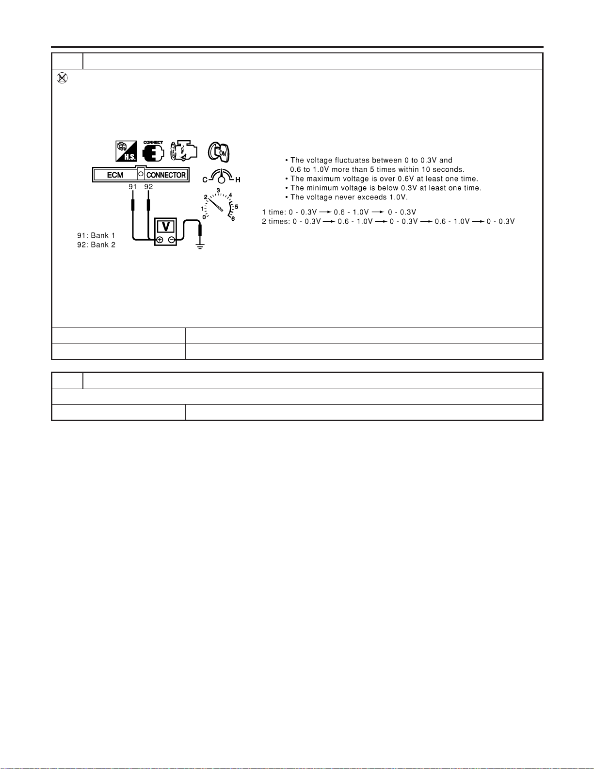
4 CHECK HEATED OXYGEN SENSOR 1
Without CONSULT-II
1. Start engine and warm it up to normal operating temperature.
2. Set voltmeter probes between ECM terminal 91 (HO2S1 bank 1 signal) or 92 (HO2S1 bank 2 signal) and engine
ground.
3. Check the following with engine speed held at 2,000 rpm constant under no load.
SEC109D
CAUTION:
I Discard any heated oxygen sensor which has been dropped from a height of more than 0.5 m (19.7 in) onto a
hard surface such as a concrete floor; use a new one.
I Before installing new oxygen sensor, clean exhaust system threads using Oxygen Sensor Thread Cleaner tool
J-43897-18 or J-43897-12 and approved anti-seize lubricant.
OK or NG
OK © GO TO 5.
NG © Replace malfunctioning heated oxygen sensor 1.
5 CHECK INTERMITTENT INCIDENT
Refer to “TROUBLE DIAGNOSIS FOR INTERMITTENT INCIDENT”, EC-156.
© INSPECTION END
DTC P0134, P0154 HO2S1
Diagnostic Procedure (Cont’d)
EC-248
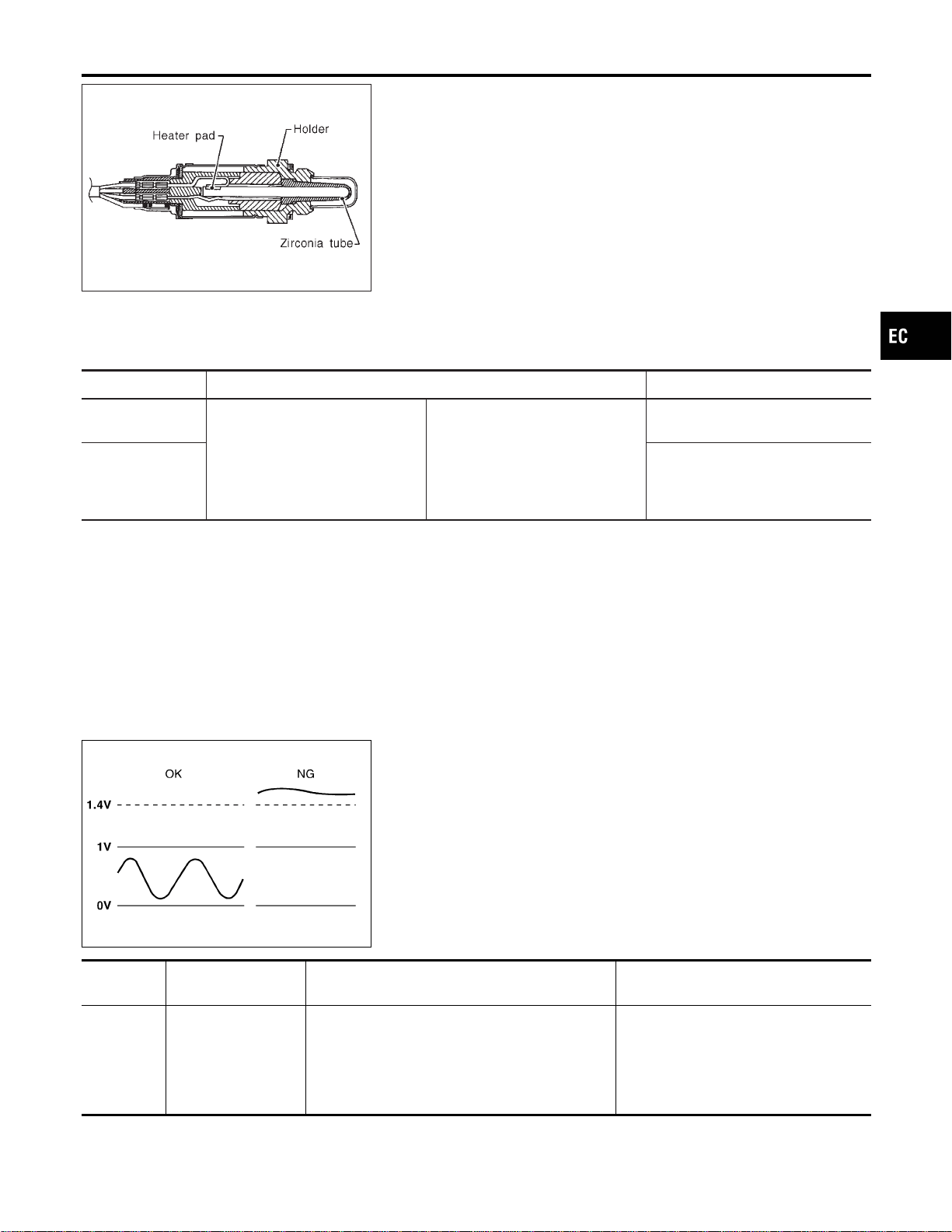
SEF327R
Component Description
NFEC0896
The heated oxygen sensor 2, after three way catalyst, monitors the
oxygen level in the exhaust gas on each bank.
Even if switching characteristics of the heated oxygen sensor 1 are
shifted, the air fuel ratio is controlled to stoichiometric, by the sig-
nal from the heated oxygen sensor 2.
This sensor is made of ceramic zirconia. The zirconia generates
voltage from approximately 1V in richer conditions to 0V in leaner
conditions.
Under normal conditions the heated oxygen sensor 2 is not used
for engine control operation.
CONSULT-II Reference Value in Data Monitor
Mode
NFEC0897
Specification data are reference values.
MONITOR ITEM CONDITION SPECIFICATION
HO2S2 (B1)
HO2S2 (B2)
I Engine: After warming up
Revving engine from idle up to
2,000 rpm
0 - 0.3V +, Approx. 0.6 - 1.0V
HO2S2 MNTR
(B1)
HO2S2 MNTR
(B2)
LEAN +, RICH
SEF305UA
On Board Diagnosis Logic
NFEC0899
The heated oxygen sensor 2 has a much longer switching time
between rich and lean than the heated oxygen sensor 1. The oxy-
gen storage capacity before the three way catalyst causes the
longer switching time. To judge the malfunctions of heated oxygen
sensor 2, ECM monitors whether the voltage is unusually high
during the various driving condition such as fuel-cut.
DTC No.
Trouble diagnosis
name
DTC Detecting Condition Possible Cause
P0138
0138
(Bank 1)
P0158
0158
(Bank 2)
Heated oxygen sen-
sor 2 circuit high volt-
age
An excessively high voltage from the sensor is
sent to ECM.
I Harness or connectors
(The sensor circuit is open or
shorted.)
I Heated oxygen sensor 2
GI
MA
EM
LC
FE
CL
MT
AT
AX
SU
BR
ST
RS
BT
HA
SC
EL
IDX
DTC P0138, P0158 HO2S2
Component Description
EC-249
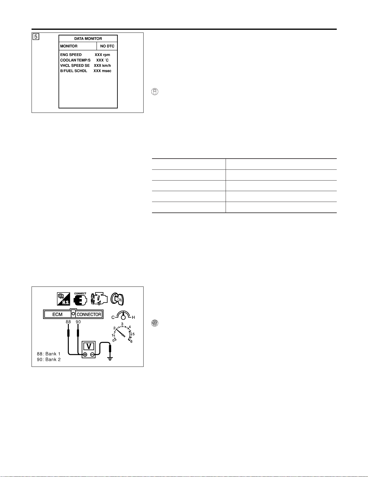
SEF189Y
DTC Confirmation Procedure
NFEC0900
CAUTION:
Always drive vehicle at a safe speed.
NOTE:
If “DTC Confirmation Procedure” has been previously conducted,
always turn ignition switch “OFF” and wait at least 10 seconds
before conducting the next test.
WITH CONSULT-II
NFEC0900S01
1) Turn ignition switch “ON” and select “DATA MONITOR” mode
with CONSULT-II.
2) Start engine and drive vehicle at a speed of more than 70 km/h
(43 MPH) for 2 consecutive minutes.
3) Stop vehicle with engine running.
4) Let engine idle for 1 minute.
5) Maintain the following conditions for at least 5 consecutive
seconds.
ENG SPEED 1,300 - 3,100 rpm
VHCL SPEED SE 64 - 130 km/h (40 - 80 MPH)
B/FUEL SCHDL 0.5 - 6.4 msec
COOLAN TEMP/S More than 70°C (158°F)
Selector lever Suitable position
6) If 1st trip DTC is detected, go to “Diagnostic Procedure”,
EC-253.
SEC903C
Overall Function Check
NFEC0901
Use this procedure to check the overall function of the heated oxy-
gen sensor 2 circuit. During this check, a 1st trip DTC might not be
confirmed.
WITH GST
NFEC0901S01
1) Start engine and drive vehicle at a speed of more than 70 km/h
(43 MPH) for 2 consecutive minutes.
2) Stop vehicle with engine running.
3) Set voltmeter probes between ECM terminal 88 (HO2S2 bank
1 signal) or 90 (HO2S2 bank 2 signal) and engine ground.
4) Check the voltage when racing up to 4,000 rpm under no load
at least 10 times.
(Depress and release accelerator pedal as soon as possible.)
The voltage should be below 1.4V during this procedure.
5) If NG, go to “Diagnostic Procedure”, EC-253.
DTC P0138, P0158 HO2S2
DTC Confirmation Procedure
EC-250
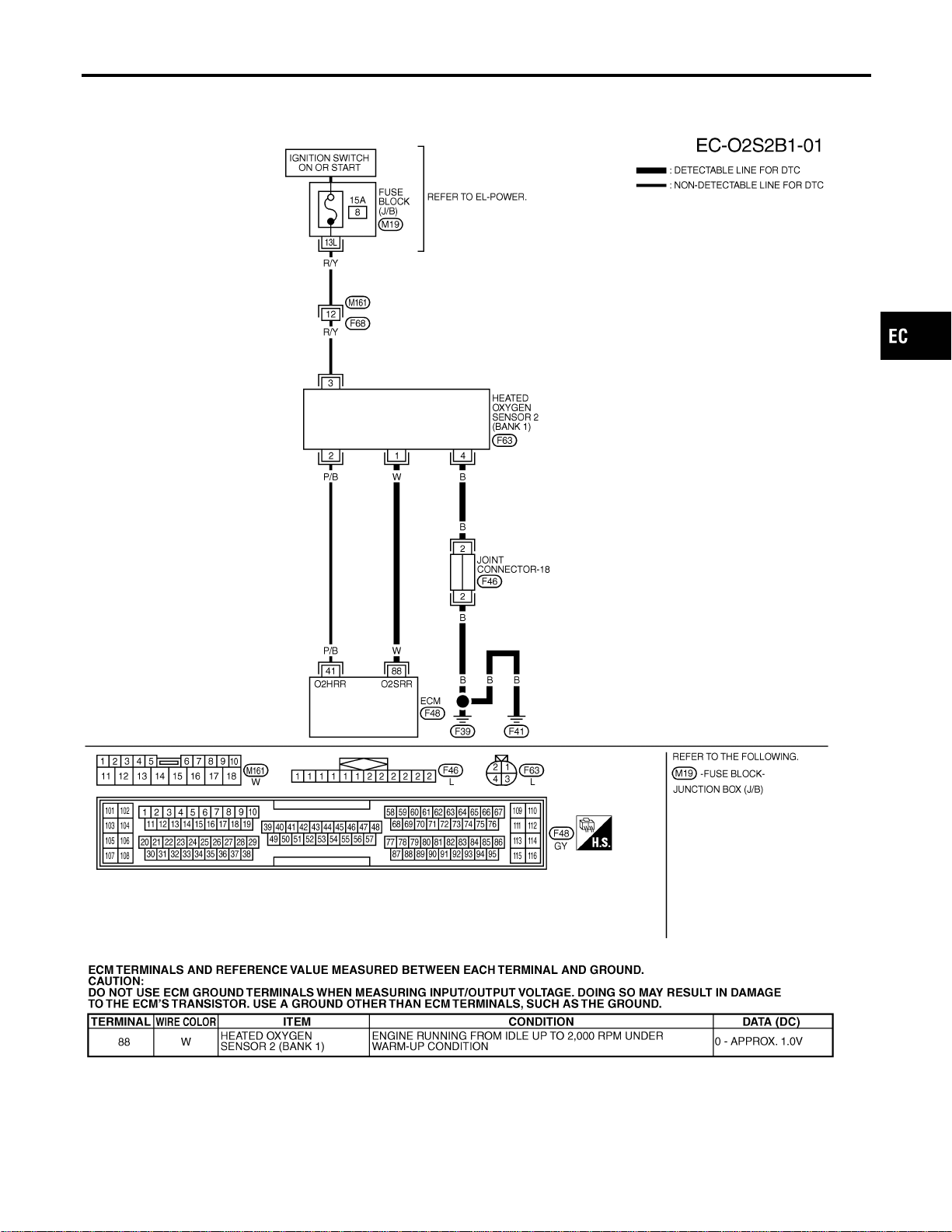
Wiring Diagram
=NFEC0902
BANK 1
NFEC0902S01
MEC483D
SEC112D
GI
MA
EM
LC
FE
CL
MT
AT
AX
SU
BR
ST
RS
BT
HA
SC
EL
IDX
DTC P0138, P0158 HO2S2
Wiring Diagram
EC-251
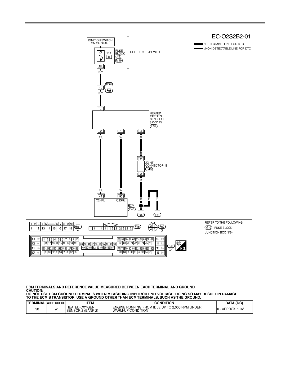
BANK 2
NFEC0902S02
MEC484D
SEC113D
DTC P0138, P0158 HO2S2
Wiring Diagram (Cont’d)
EC-252
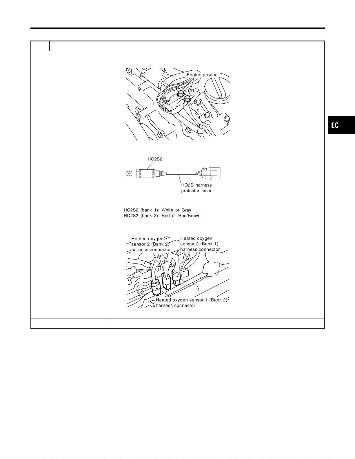
Diagnostic Procedure
NFEC0903
1 INSPECTION START
1. Turn ignition switch “OFF”.
2. Loosen and retighten engine ground screws.
SEC047D
3. Check heated oxygen sensor 2 harness protector color.
SEF372ZB
4. Disconnect corresponding heated oxygen sensor 2 harness connector.
SEC134D
5. Disconnect ECM harness connector.
© GO TO 2.
GI
MA
EM
LC
FE
CL
MT
AT
AX
SU
BR
ST
RS
BT
HA
SC
EL
IDX
DTC P0138, P0158 HO2S2
Diagnostic Procedure
EC-253
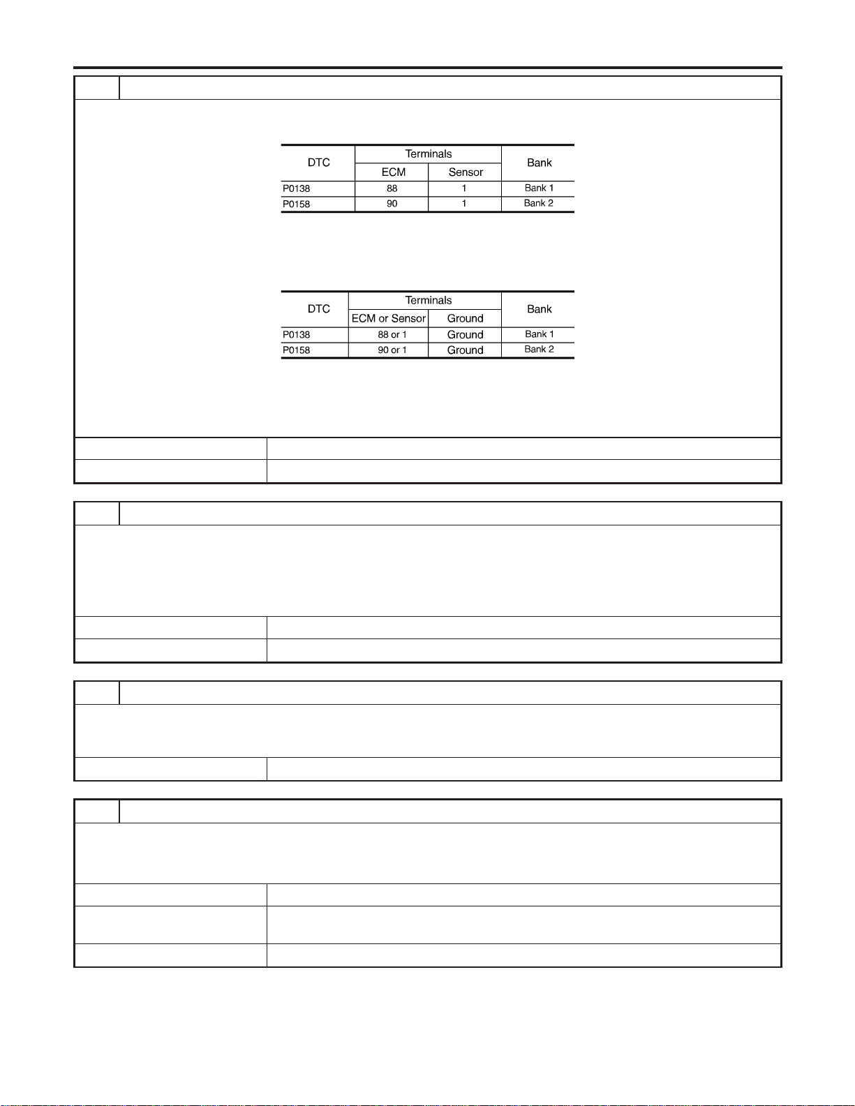
2 CHECK HO2S2 INPUT SIGNAL CIRCUIT FOR OPEN AND SHORT
1. Check harness continuity between ECM terminal and HO2S2 terminal as follows.
Refer to Wiring Diagram.
MTBL1150
Continuity should exist.
2. Check harness continuity between ECM terminal or HO2S2 terminal and ground as follows.
Refer to Wiring Diagram.
MTBL1151
Continuity should not exist.
3. Also check harness for short to power.
OK or NG
OK © GO TO 3.
NG © Repair open circuit or short to ground or short to power in harness or connectors.
3 CHECK HO2S2 GROUND CIRCUIT FOR OPEN AND SHORT
1. Check harness continuity between HO2S2 terminal 4 and engine ground.
Refer to Wiring Diagram.
Continuity should exist.
2. Also check harness for short to power.
OK or NG
OK © GO TO 5.
NG © GO TO 4.
4 DETECT MALFUNCTIONING PART
Check the following.
I Joint connector-18
I Harness for open and short between HO2S2 and engine ground
© Repair open circuit or short to power in harness or connectors.
5 CHECK HO2S2 CONNECTORS FOR WATER
Check heated oxygen sensor connector 2 and harness connector for water.
Water should not exist.
OK or NG
OK (With CONSULT-II) © GO TO 6.
OK (Without CONSULT-
II)
© GO TO 7.
NG © Repair or replace harness or connectors.
DTC P0138, P0158 HO2S2
Diagnostic Procedure (Cont’d)
EC-254
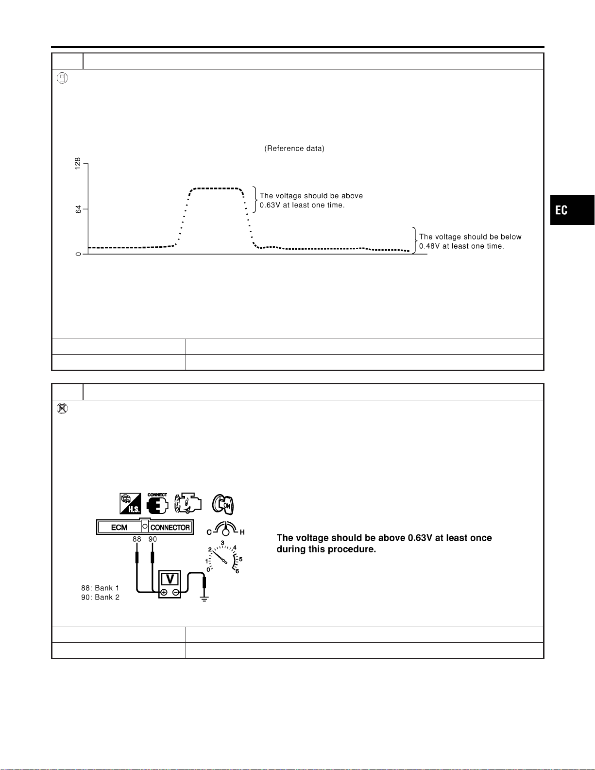
6 CHECK HEATED OXYGEN SENSOR 2
With CONSULT-II
1. Start engine and drive vehicle at a speed of more than 70 km/h (43 MPH) for 2 consecutive minutes.
2. Stop vehicle with engine running.
3. Select “FUEL INJECTION” in “ACTIVE TEST” mode, and select “HO2S2 (B1)/(B2)” as the monitor item with CONSULT-
II.
4. Check “HO2S2 (B1)/(B2)” at idle speed when adjusting “FUEL INJECTION” to ±25%.
SEF066YA
“HO2S2 (B1)/(B2)” should be above 0.63V at least once when the “FUEL INJECTION” is +25%.
“HO2S2 (B1)/(B2)” should be below 0.48V at least once when the “FUEL INJECTION” is −25%.
CAUTION:
Discard any heated oxygen sensor which has been dropped from a height of more than 0.5 m (19.7 in) onto a
hard surface such as a concrete floor; use a new one.
OK or NG
OK © GO TO 10.
NG © GO TO 9.
7 CHECK HEATED OXYGEN SENSOR 2-I
Without CONSULT-II
1. Start engine and drive vehicle at a speed of more than 70 km/h (43 MPH) for 2 consecutive minutes.
2. Stop vehicle with engine running.
3. Set voltmeter probes between ECM terminal 88 (HO2S2 bank 1 signal) or 90 (HO2S2 bank 2 signal) and engine
ground.
4. Check the voltage when revving up to 4,000 rpm under no load at least 10 times.
(Depress and release accelerator pedal as soon as possible.)
SEC114D
OK or NG
OK © GO TO 10.
NG © GO TO 8.
GI
MA
EM
LC
FE
CL
MT
AT
AX
SU
BR
ST
RS
BT
HA
SC
EL
IDX
DTC P0138, P0158 HO2S2
Diagnostic Procedure (Cont’d)
EC-255
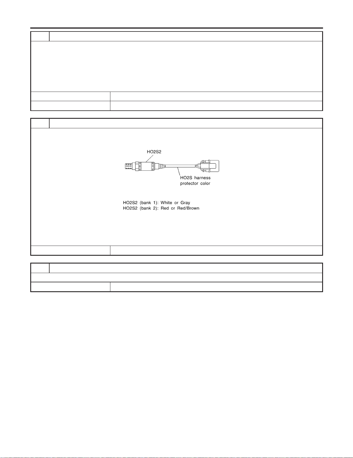
8 CHECK HEATED OXYGEN SENSOR 2-II
Idle vehicle for 10 minutes, then check voltage between the same terminals as in Test No. 7; or check voltage when coast-
ing from 80 km/h (50 MPH) in 3rd gear position (M/T), “D” position with “OD” OFF (A/T).
The voltage should go below 0.48V at least once during this procedure.
CAUTION:
Discard any heated oxygen sensor which has been dropped from a height of more than 0.5 m (19.7 in) onto a
hard surface such as a concrete floor; use a new one.
OK or NG
OK © GO TO 10.
NG © GO TO 9.
9 REPLACE HEATED OXYGEN SENSOR 2
1. Stop vehicle and turn ignition switch “OFF”.
2. Check heated oxygen sensor 2 harness protector color.
SEF372ZB
CAUTION:
Before installing new oxygen sensor, clean exhaust system threads using Oxygen Sensor Thread Cleaner tool
J-43897-18 or J-43897-12 and approved anti-seize lubricant.
© Replace malfunctioning heated oxygen sensor 2.
10 CHECK INTERMITTENT INCIDENT
Refer to “TROUBLE DIAGNOSIS FOR INTERMITTENT INCIDENT”, EC-156.
© INSPECTION END
DTC P0138, P0158 HO2S2
Diagnostic Procedure (Cont’d)
EC-256
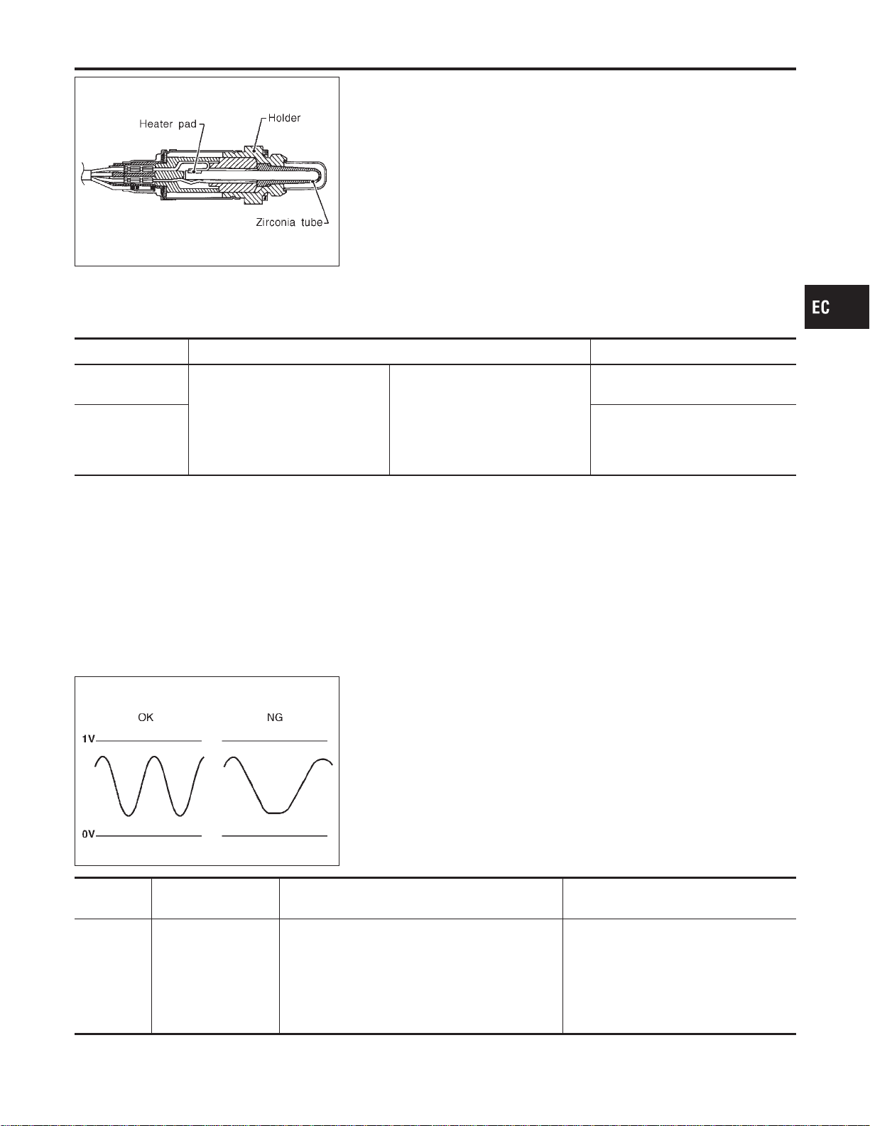
SEF327R
Component Description
NFEC0904
The heated oxygen sensor 2, after three way catalyst, monitors the
oxygen level in the exhaust gas on each bank.
Even if switching characteristics of the heated oxygen sensor 1 are
shifted, the air fuel ratio is controlled to stoichiometric, by the sig-
nal from the heated oxygen sensor 2.
This sensor is made of ceramic zirconia. The zirconia generates
voltage from approximately 1V in richer conditions to 0V in leaner
conditions.
Under normal conditions the heated oxygen sensor 2 is not used
for engine control operation.
CONSULT-II Reference Value in Data Monitor
Mode
NFEC0905
Specification data are reference values.
MONITOR ITEM CONDITION SPECIFICATION
HO2S2 (B1)
HO2S2 (B2)
I Engine: After warming up
Revving engine from idle up to
2,000 rpm
0 - 0.3V +, Approx. 0.6 - 1.0V
HO2S2 MNTR
(B1)
HO2S2 MNTR
(B2)
LEAN +, RICH
SEF302U
On Board Diagnosis Logic
NFEC0907
The heated oxygen sensor 2 has a much longer switching time
between rich and lean than the heated oxygen sensor 1. The oxy-
gen storage capacity before the three way catalyst causes the
longer switching time. To judge the malfunctions of heated oxygen
sensor 2, ECM monitors whether the switching response of the
sensor’s voltage is faster than specified during the various driving
condition such as fuel-cut.
DTC No.
Trouble diagnosis
name
DTC Detecting Condition Possible Cause
P0139
0139
(Bank 1)
P0159
0159
(Bank 2)
Heated oxygen sen-
sor 2 circuit slow
response
It takes more time for the sensor to respond
between rich and lean than the specified time.
I Harness or connectors
(The sensor circuit is open or
shorted.)
I Heated oxygen sensor 2
I Fuel pressure
I Injectors
I Intake air leaks
GI
MA
EM
LC
FE
CL
MT
AT
AX
SU
BR
ST
RS
BT
HA
SC
EL
IDX
DTC P0139, P0159 HO2S2
Component Description
EC-257
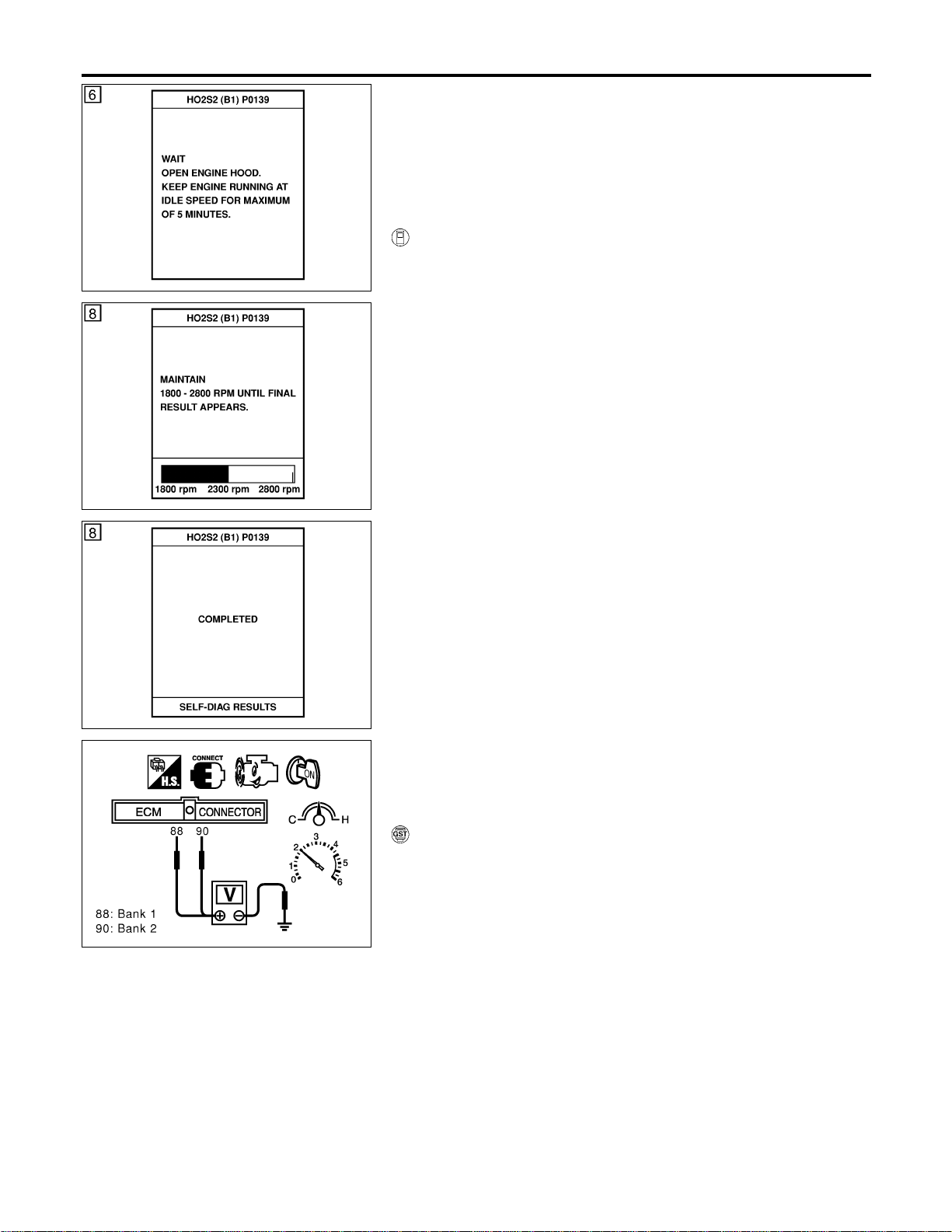
SEF666Y
DTC Confirmation Procedure
NFEC0908
SEF667Y
SEF668Y
NOTE:
If “DTC Confirmation Procedure” has been previously conducted,
always turn ignition switch “OFF” and wait at least 10 seconds
before conducting the next test.
TESTING CONDITION:
Open engine hood before conducting following procedure.
WITH CONSULT-II
NFEC0908S01
1) Start engine and warm it up to normal operating temperature.
2) Turn ignition switch “OFF” and wait at least 10 seconds.
3) Turn ignition switch “ON”.
4) Select “DATA MONITOR” mode with CONSULT-II.
5) Make sure that “COOLAN TEMP/S” indicates more than 70°C
(158°F).
6) Select “HO2S2 (B1)/(B2) P0139/P0159” of “HO2S2” in “DTC
WORK SUPPORT” mode with CONSULT-II.
7) Start engine and follow the instruction of CONSULT-II.
8) Make sure that “OK” is displayed after touching “SELF-DIAG
RESULTS”.
If NG is displayed, refer to “Diagnostic Procedure”, EC-262.
If “CANNOT BE DIAGNOSED” is displayed, perform the fol-
lowing.
a) Stop engine and cool down until “COOLAN TEMP/S” indicates
less than 70°C (158°F).
b) Turn ignition switch “ON”.
c) Select “DATA MONITOR” mode with CONSULT-II.
d) Start engine.
e) Return to step 6 again when the “COOLAN TEMP/S” reaches
to 70°C (158°F).
SEC903C
Overall Function Check
NFEC0909
Use this procedure to check the overall function of the heated oxy-
gen sensor 2 circuit. During this check, a 1st trip DTC might not be
confirmed.
WITH GST
NFEC0909S01
1) Start engine and drive vehicle at a speed of more than 70 km/h
(43 MPH) for 2 consecutive minutes.
2) Stop vehicle with engine running.
3) Set voltmeter probes between ECM terminal 88 (HO2S2 bank
1 signal) or 90 (HO2S2 bank 2 signal) and engine ground.
4) Check the voltage when racing up to 4,000 rpm under no load
at least 10 times.
(Depress and release accelerator pedal as soon as possible.)
The voltage should change at more than 0.06V for 1 sec-
ond during this procedure.
If the voltage can be confirmed in step 4, step 5 is not
necessary.
5) Keep vehicle at idling for 10 minutes, then check the voltage.
Or check the voltage when coasting from 80 km/h (50 MPH)
in 3rd gear position (M/T), “D” position with “OD” OFF (A/T).
The voltage should change at more than 0.06V for 1 sec-
ond during this procedure.
DTC P0139, P0159 HO2S2
DTC Confirmation Procedure
EC-258

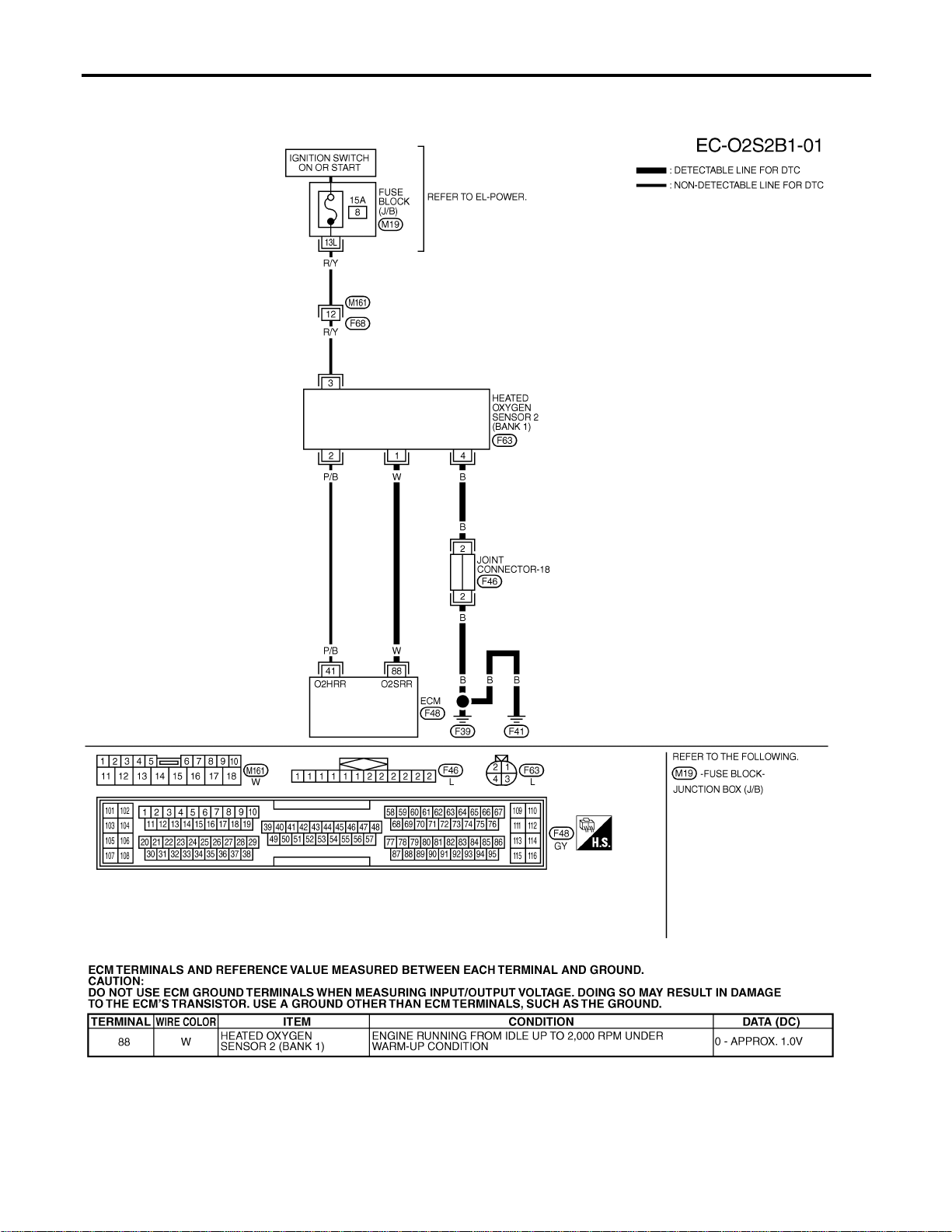
Wiring Diagram
=NFEC0910
BANK 1
NFEC0910S01
MEC483D
SEC112D
DTC P0139, P0159 HO2S2
Wiring Diagram
EC-260

BANK 2
NFEC0910S02
MEC484D
SEC113D
GI
MA
EM
LC
FE
CL
MT
AT
AX
SU
BR
ST
RS
BT
HA
SC
EL
IDX
DTC P0139, P0159 HO2S2
Wiring Diagram (Cont’d)
EC-261
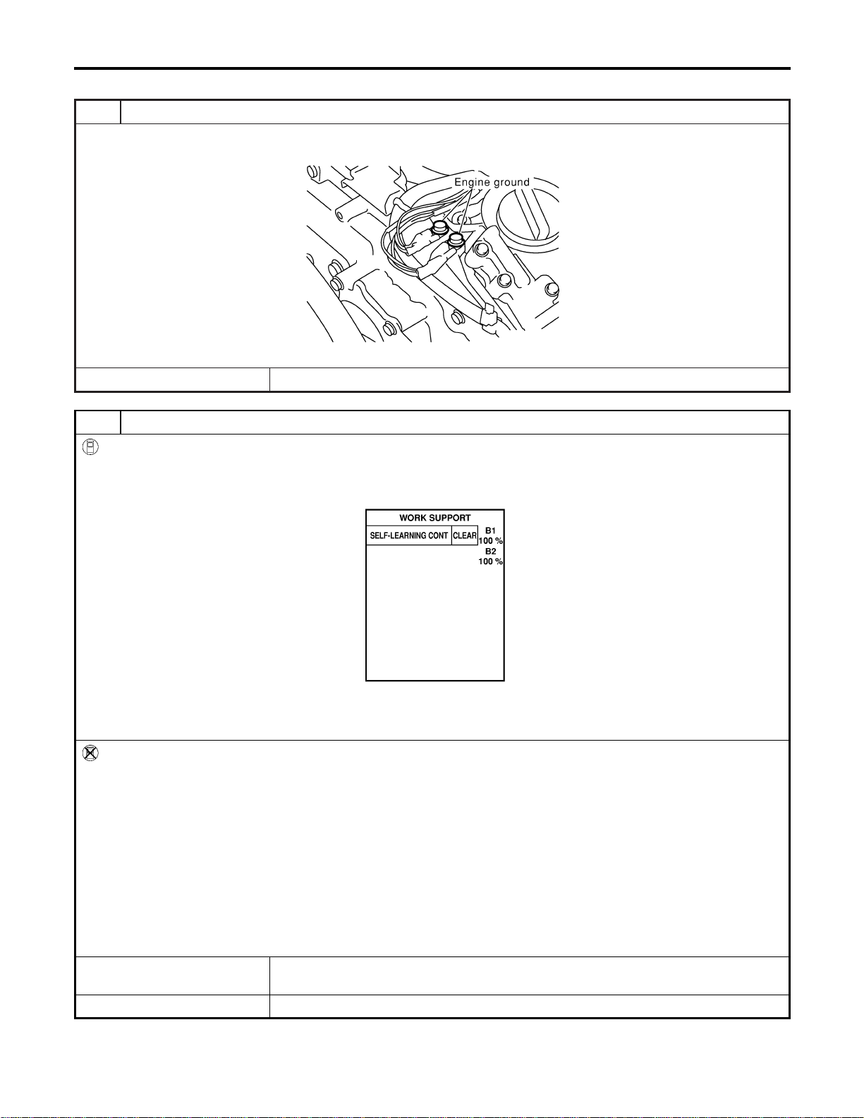
Diagnostic Procedure
NFEC0911
1 RETIGHTEN GROUND SCREWS
1. Turn ignition switch “OFF”.
2. Loosen and retighten engine ground screws.
SEC047D
© GO TO 2.
2 CLEAR THE SELF-LEARNING DATA
With CONSULT-II
1. Start engine and warm it up to normal operating temperature.
2. Select “SELF-LEARNING CONT” in “WORK SUPPORT” mode with CONSULT-II.
3. Clear the self-learning control coefficient by touching “CLEAR”.
SEF968Y
4. Run engine for at least 10 minutes at idle speed.
Is the 1st trip DTC P0171, P0172, P0174 or P0175 detected?
Is it difficult to start engine?
Without CONSULT-II
1. Start engine and warm it up to normal operating temperature.
2. Turn ignition switch “OFF”.
3. Disconnect mass air flow sensor harness connector, and restart and run engine for at least 5 seconds at idle speed.
4. Stop engine and reconnect mass air flow sensor harness connector.
5. Make sure 1st trip DTC No. P0102 is displayed.
6. Erase the 1st trip DTC memory. Refer to “HOW TO ERASE EMISSION-RELATED DIAGNOSTIC INFORMATION”,
EC-91.
7. Make sure DTC No. P0000 is displayed.
8. Run engine for at least 10 minutes at idle speed.
Is the 1st trip DTC P0171, P0172, P0174 or P0175 detected?
Is it difficult to start engine?
YesorNo
Yes © Perform trouble diagnosis for DTC P0171, P0174 or P0172, P0175. Refer to EC-267,
275.
No © GO TO 3.
DTC P0139, P0159 HO2S2
Diagnostic Procedure
EC-262
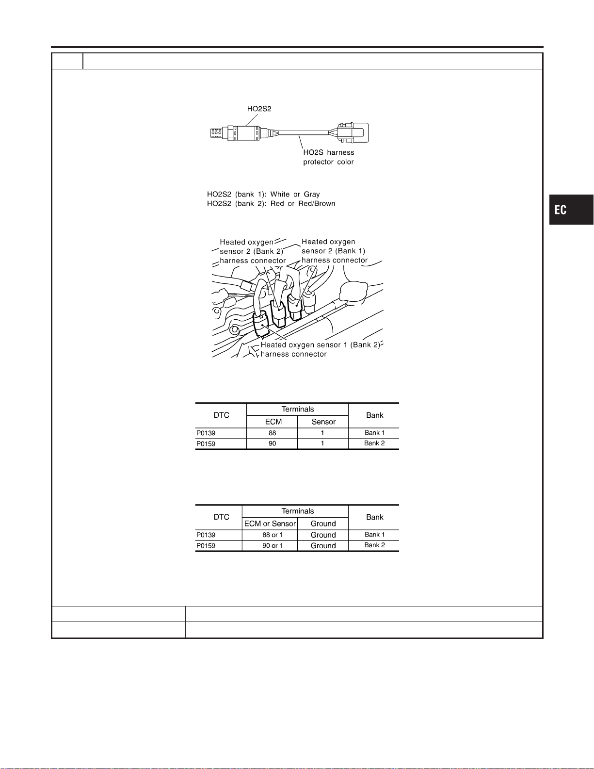
3 CHECK HO2S2 INPUT SIGNAL CIRCUIT FOR OPEN AND SHORT
1. Turn ignition switch “OFF”.
2. Check heated oxygen sensor 2 harness protector color.
SEF372ZB
3. Disconnect corresponding heated oxygen sensor 2 harness connector.
SEC134D
4. Disconnect ECM harness connector.
5. Check harness continuity between ECM terminal and HO2S2 terminal as follows.
Refer to Wiring Diagram.
MTBL1152
Continuity should exist.
6. Check harness continuity between ECM terminal or HO2S2 terminal and ground as follows.
Refer to Wiring Diagram.
MTBL1153
Continuity should not exist.
7. Also check harness for short to power.
OK or NG
OK © GO TO 4.
NG © Repair open circuit or short to ground or short to power in harness or connectors.
GI
MA
EM
LC
FE
CL
MT
AT
AX
SU
BR
ST
RS
BT
HA
SC
EL
IDX
DTC P0139, P0159 HO2S2
Diagnostic Procedure (Cont’d)
EC-263
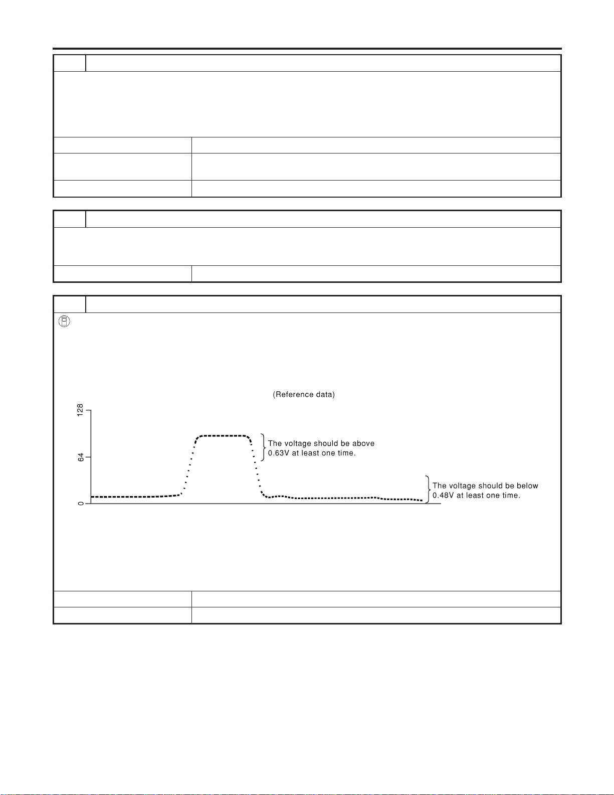
4 CHECK HO2S2 GROUND CIRCUIT FOR OPEN AND SHORT
1. Check harness continuity between HO2S2 terminal 4 and engine ground.
Refer to Wiring Diagram.
Continuity should exist.
2. Also check harness for short to power.
OK or NG
OK (With CONSULT-II) © GO TO 6.
OK (Without CONSULT-
II)
© GO TO 7.
NG © GO TO 5.
5 DETECT MALFUNCTIONING PART
Check the following.
I Joint connector-18
I Harness for open and short between HO2S2 and engine ground
© Repair open circuit or short to power in harness or connectors.
6 CHECK HEATED OXYGEN SENSOR 2
With CONSULT-II
1. Start engine and drive vehicle at a speed of more than 70 km/h (43 MPH) for 2 consecutive minutes.
2. Stop vehicle with engine running.
3. Select “FUEL INJECTION” in “ACTIVE TEST” mode, and select “HO2S2 (B1)/(B2)” as the monitor item with CONSULT-
II.
4. Check “HO2S2 (B1)/(B2)” at idle speed when adjusting “FUEL INJECTION” to ±25%.
SEF066YA
“HO2S2 (B1)/(B2)” should be above 0.63V at least once when the “FUEL INJECTION” is +25%.
“HO2S2 (B1)/(B2)” should be below 0.48V at least once when the “FUEL INJECTION” is −25%.
CAUTION:
Discard any heated oxygen sensor which has been dropped from a height of more than 0.5 m (19.7 in) onto a
hard surface such as a concrete floor; use a new one.
OK or NG
OK © GO TO 10.
NG © GO TO 9.
DTC P0139, P0159 HO2S2
Diagnostic Procedure (Cont’d)
EC-264
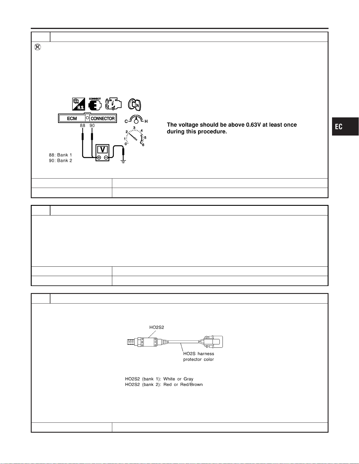
7 CHECK HEATED OXYGEN SENSOR 2-I
Without CONSULT-II
1. Start engine and drive vehicle at a speed of more than 70 km/h (43 MPH) for 2 consecutive minutes.
2. Stop vehicle with engine running.
3. Set voltmeter probes between ECM terminal 88 (HO2S2 bank 1 signal) or 90 (HO2S2 bank 2 signal) and engine
ground.
4. Check the voltage when revving up to 4,000 rpm under no load at least 10 times.
(Depress and release accelerator pedal as soon as possible.)
SEC114D
OK or NG
OK © GO TO 10.
NG © GO TO 8.
8 CHECK HEATED OXYGEN SENSOR 2-II
Idle vehicle for 10 minutes, then check voltage between the same terminals as in Test No. 7; or check voltage when coast-
ing from 80 km/h (50 MPH) in 3rd gear position (M/T), “D” position with “OD” OFF (A/T).
The voltage should go below 0.48V at least once during this procedure.
CAUTION:
Discard any heated oxygen sensor which has been dropped from a height of more than 0.5 m (19.7 in) onto a
hard surface such as a concrete floor; use a new one.
OK or NG
OK © GO TO 10.
NG © GO TO 9.
9 REPLACE HEATED OXYGEN SENSOR 2
1. Stop vehicle and turn ignition switch “OFF”.
2. Check heated oxygen sensor 2 harness protector color.
SEF372ZB
CAUTION:
Before installing new oxygen sensor, clean exhaust system threads using Oxygen Sensor Thread Cleaner tool
J-43897-18 or J-43897-12 and approved anti-seize lubricant.
© Replace malfunctioning heated oxygen sensor 2.
GI
MA
EM
LC
FE
CL
MT
AT
AX
SU
BR
ST
RS
BT
HA
SC
EL
IDX
DTC P0139, P0159 HO2S2
Diagnostic Procedure (Cont’d)
EC-265

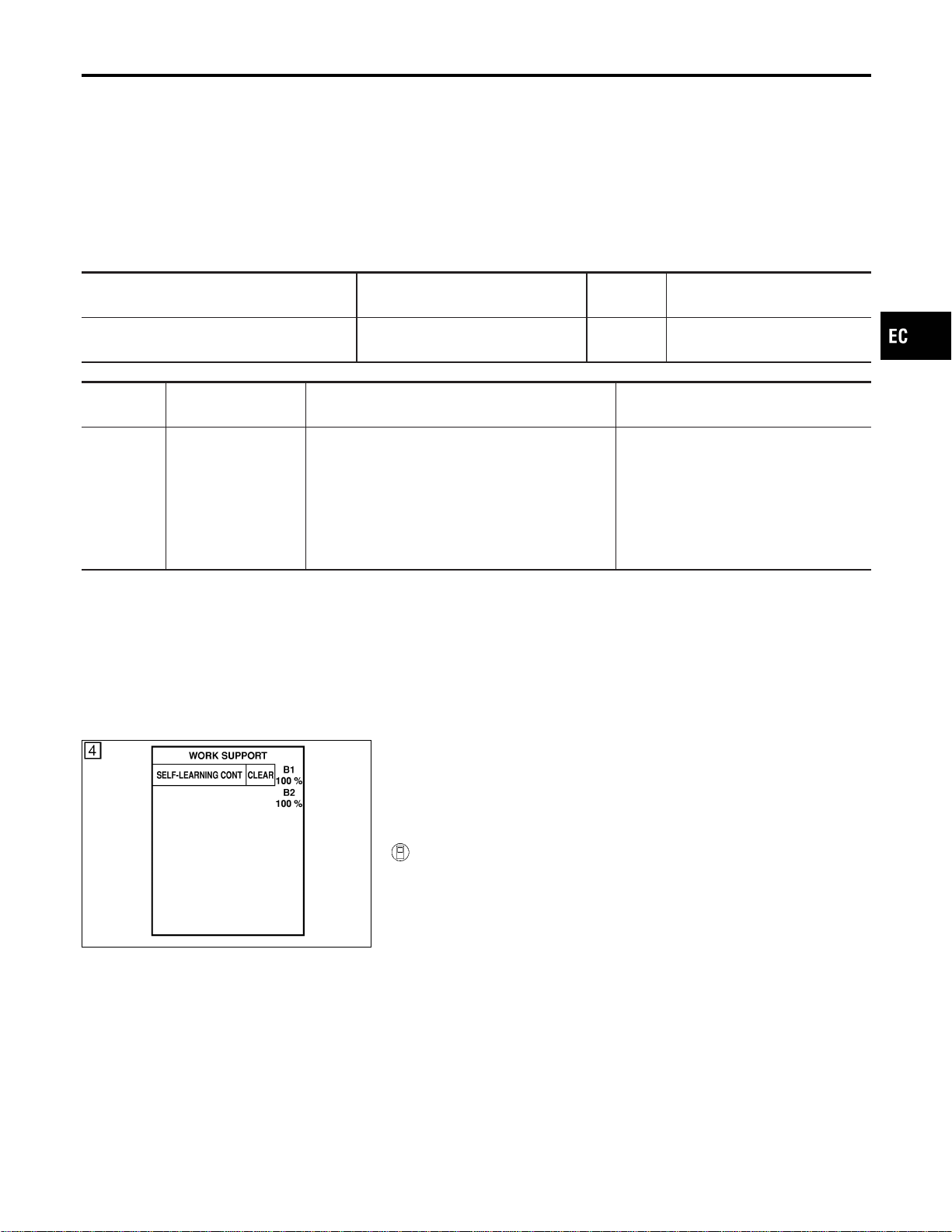
On Board Diagnosis Logic
NFEC0912
With the Air/Fuel Mixture Ratio Self-Learning Control, the actual
mixture ratio can be brought closely to the theoretical mixture ratio
based on the mixture ratio feedback signal from the heated oxygen
sensors 1. The ECM calculates the necessary compensation to
correct the offset between the actual and the theoretical ratios.
In case the amount of the compensation value is extremely large
(The actual mixture ratio is too lean.), the ECM judges the condi-
tion as the fuel injection system malfunction and light up the MIL
(2 trip detection logic).
Sensor Input Signal to ECM
ECM func-
tion
Actuator
Heated oxygen sensors 1
Density of oxygen in exhaust gas
(Mixture ratio feedback signal)
Fuel injec-
tion control
Injectors
DTC No.
Trouble diagnosis
name
DTC Detecting Condition Possible Cause
P0171
0171
(Bank 1)
P0174
0174
(Bank 2)
Fuel injection system
too lean
Fuel injection system does not operate Properly,
the amount of mixture ratio compensation is too
large. (The mixture ratio is too lean.)
I Intake air leaks
I Heated oxygen sensor 1
I Injectors
I Exhaust gas leaks
I Incorrect fuel pressure
I Lack of fuel
I Mass air flow sensor
I Incorrect PCV hose connection
SEF968Y
DTC Confirmation Procedure
NFEC0913
NOTE:
If “DTC Confirmation Procedure” has been previously conducted,
always turn ignition switch “OFF” and wait at least 10 seconds
before conducting the next test.
WITH CONSULT-II
NFEC0913S01
1) Start engine and warm it up to normal operating temperature.
2) Turn ignition switch “OFF” and wait at least 10 seconds.
3) Turn ignition switch “ON” and select “SELF-LEARN CON-
TROL” in “WORK SUPPORT” mode with CONSULT-II.
4) Clear the self-learning control coefficient by touching “CLEAR”.
5) Select “DATA MONITOR” mode with CONSULT-II.
6) Start engine again and let it idle for at least 10 minutes.
The 1st trip DTC P0171 or P0174 should be detected at this
stage, if a malfunction exists. If so, go to “Diagnostic
Procedure”, EC-271.
7) If it is difficult to start engine at step 6, the fuel injection sys-
tem has a malfunction, too.
8) Crank engine while depressing accelerator pedal. If engine
starts, go to “Diagnostic Procedure”, EC-271. If engine does
not start, check exhaust and intake air leak visually.
GI
MA
EM
LC
FE
CL
MT
AT
AX
SU
BR
ST
RS
BT
HA
SC
EL
IDX
DTC P0171, P0174 FUEL INJECTION SYSTEM FUNCTION
On Board Diagnosis Logic
EC-267
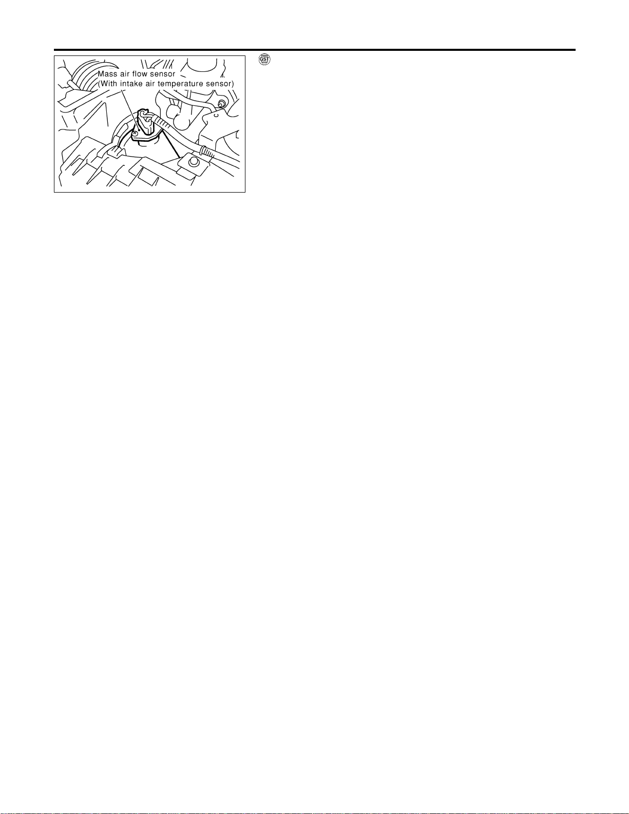
SEC055D
WITH GST
NFEC0913S02
1) Start engine and warm it up to normal operating temperature.
2) Turn ignition switch “OFF” and wait at least 10 seconds.
3) Disconnect mass air flow sensor harness connector. Then
restart and run engine for at least 5 seconds at idle speed.
4) Stop engine and reconnect mass air flow sensor harness con-
nector.
5) Select “MODE 7” with GST. Make sure DTC P0102 is detected.
6) Select “MODE 4” with GST and erase the DTC P0102.
7) Start engine again and let it idle for at least 10 minutes.
8) Select “MODE 7” with GST. The 1st trip DTC P0171 or P0174
should be detected at this stage, if a malfunction exists. If so,
go to “Diagnostic Procedure”, EC-271.
9) If it is difficult to start engine at step 7, the fuel injection sys-
tem has a malfunction.
10) Crank engine while depressing accelerator pedal. If engine
starts, go to “Diagnostic Procedure”, EC-271. If engine does
not start, check exhaust and intake air leak visually.
DTC P0171, P0174 FUEL INJECTION SYSTEM FUNCTION
DTC Confirmation Procedure (Cont’d)
EC-268
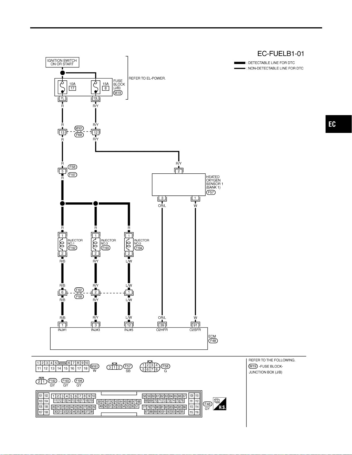
Wiring Diagram
NFEC0914
BANK 1
NFEC0914S01
MEC487D
GI
MA
EM
LC
FE
CL
MT
AT
AX
SU
BR
ST
RS
BT
HA
SC
EL
IDX
DTC P0171, P0174 FUEL INJECTION SYSTEM FUNCTION
Wiring Diagram
EC-269
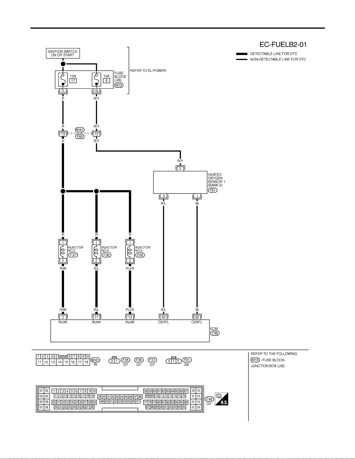
BANK 2
NFEC0914S02
MEC488D
DTC P0171, P0174 FUEL INJECTION SYSTEM FUNCTION
Wiring Diagram (Cont’d)
EC-270
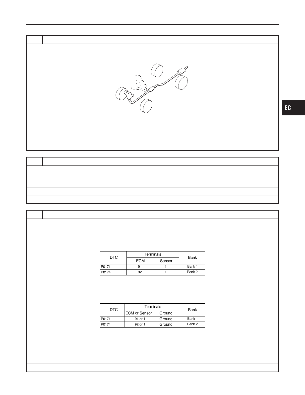
Diagnostic Procedure
NFEC0915
1 CHECK EXHAUST AIR LEAK
1. Start engine and run it at idle.
2. Listen for an exhaust air leak before three way catalyst.
SEF099P
OK or NG
OK © GO TO 2.
NG © Repair or replace.
2 CHECK FOR INTAKE AIR LEAK
1. Listen for an intake air leak after the mass air flow sensor.
2. Check PCV hose connection.
OK or NG
OK © GO TO 3.
NG © Repair or replace.
3 CHECK HEATED OXYGEN SENSOR 1 CIRCUIT FOR OPEN AND SHORT
1. Turn ignition switch “OFF”.
2. Disconnect corresponding heated oxygen sensor 1 harness connector.
3. Disconnect ECM harness connector.
4. Check harness continuity between ECM terminal and HO2S1 terminal as follows.
Refer to Wiring Diagram.
MTBL1154
Continuity should exist.
5. Check harness continuity between ECM terminal or HO2S1 terminal and ground as follows.
Refer to Wiring Diagram.
MTBL1155
Continuity should not exist.
6. Also check harness for short to power.
OK or NG
OK © GO TO 4.
NG © Repair open circuit or short to ground or short to power in harness or connectors.
GI
MA
EM
LC
FE
CL
MT
AT
AX
SU
BR
ST
RS
BT
HA
SC
EL
IDX
DTC P0171, P0174 FUEL INJECTION SYSTEM FUNCTION
Diagnostic Procedure
EC-271
4 CHECK FUEL PRESSURE
1. Release fuel pressure to zero. Refer to EC-56.
2. Install fuel pressure gauge and check fuel pressure. Refer to EC-56.
At idling:
Approximately 350 kPa (3.7 kg/cm
2
, 51 psi)
OK or NG
OK © GO TO 5.
NG © Follow the construction of “Fuel Pressure Check”, EC-56.
5 CHECK MASS AIR FLOW SENSOR
With CONSULT-II
1. Install all removed parts.
2. Check “MASS AIR FLOW” in “DATA MONITOR” mode with CONSULT-II.
2.0 - 6.0 g·m/sec: at idling
7.0 - 20.0 g·m/sec: at 2,500 rpm
With GST
1. Install all removed parts.
2. Check mass air flow sensor signal in MODE 1 with GST.
2.0 - 6.0 g·m/sec: at idling
7.0 - 20.0 g·m/sec: at 2,500 rpm
OK or NG
OK © GO TO 6.
NG © Check connectors for rusted terminals or loose connections in the mass air flow sensor
circuit or engine grounds. Refer to EC-198.
DTC P0171, P0174 FUEL INJECTION SYSTEM FUNCTION
Diagnostic Procedure (Cont’d)
EC-272
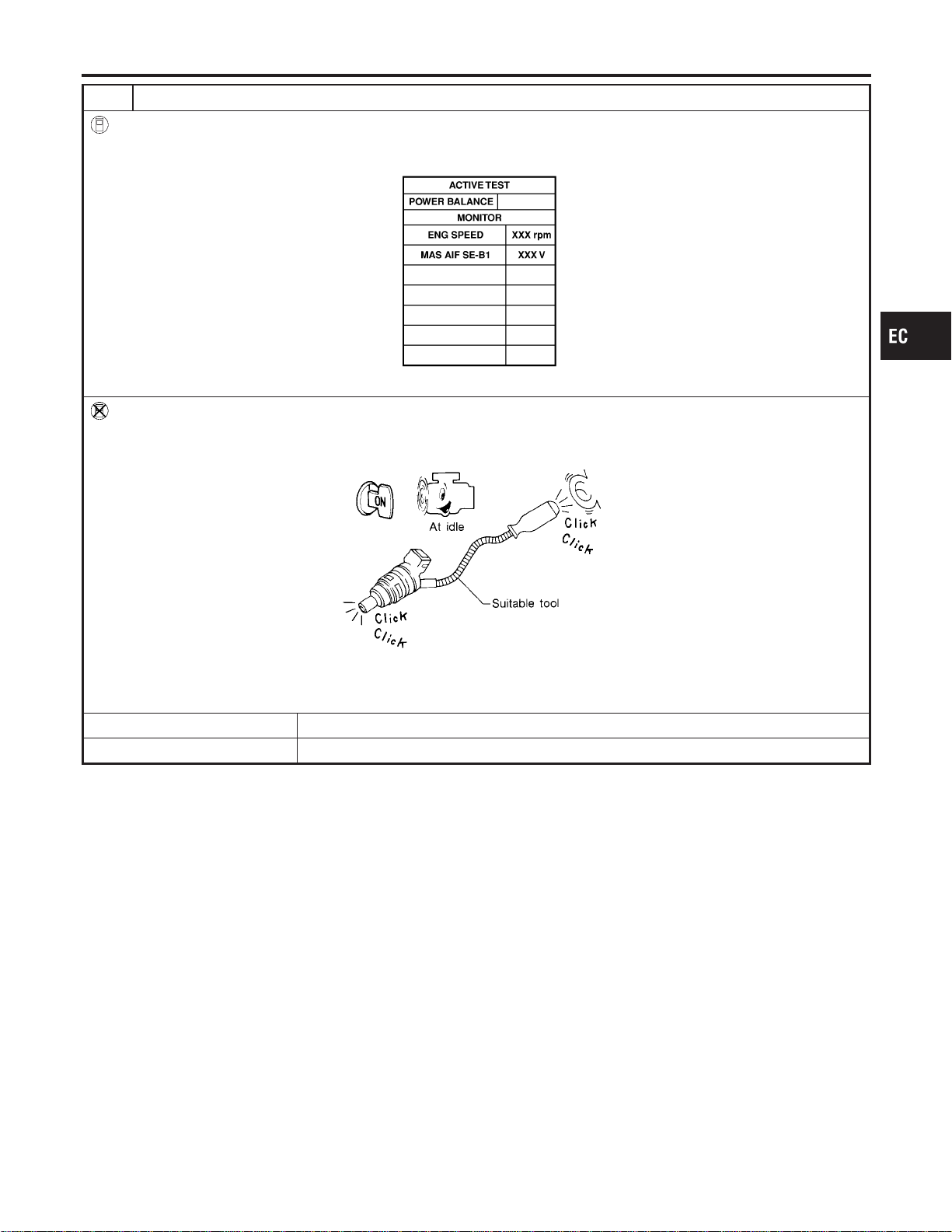
6 CHECK FUNCTION OF INJECTORS
With CONSULT-II
1. Start engine.
2. Perform “POWER BALANCE” in “ACTIVE TEST” mode with CONSULT-II.
SEC136D
3. Make sure that each circuit produces a momentary engine speed drop.
Without CONSULT-II
1. Start engine.
2. Listen to each injector operating sound.
MEC703B
Clicking noise should be heard.
OK or NG
OK © GO TO 7.
NG © Perform trouble diagnosis for “INJECTORS”, EC-703.
GI
MA
EM
LC
FE
CL
MT
AT
AX
SU
BR
ST
RS
BT
HA
SC
EL
IDX
DTC P0171, P0174 FUEL INJECTION SYSTEM FUNCTION
Diagnostic Procedure (Cont’d)
EC-273

7 CHECK INJECTOR
1. Confirm that the engine is cooled down and there are no fire hazards near the vehicle.
2. Turn ignition switch “OFF”.
3. Disconnect injector harness connectors on bank 2 (for DTC P0171), bank 1 (for DTC P0174).
4. Remove injector gallery assembly. Refer to EC-57.
Keep fuel hose and all injectors connected to injector gallery.
The injector harness connectors on bank 1 (for DTC P0171), bank 2 (for DTC P0174) should remain connected.
5. Disconnect all ignition coil harness connectors.
6. Prepare pans or saucers under each injector.
7. Crank engine for about 3 seconds. Make sure that fuel sprays out from injectors.
SEF595Q
Fuel should be sprayed evenly for each injector.
OK or NG
OK © GO TO 8.
NG © Replace injectors from which fuel does not spray out. Always replace O-ring with new
ones.
8 CHECK INTERMITTENT INCIDENT
Refer to “TROUBLE DIAGNOSIS FOR INTERMITTENT INCIDENT”, EC-156.
© INSPECTION END
DTC P0171, P0174 FUEL INJECTION SYSTEM FUNCTION
Diagnostic Procedure (Cont’d)
EC-274
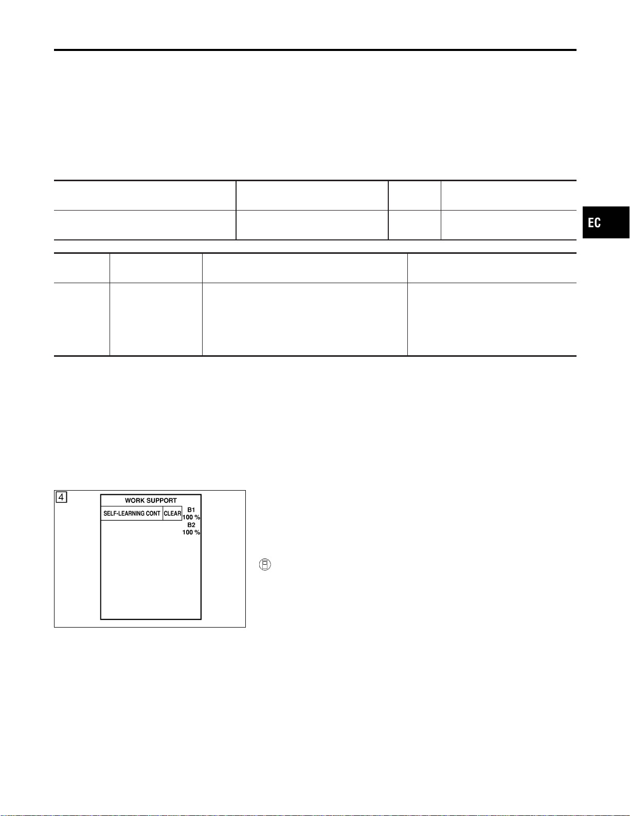
On Board Diagnosis Logic
NFEC0916
With the Air/Fuel Mixture Ratio Self-Learning Control, the actual
mixture ratio can be brought closely to the theoretical mixture ratio
based on the mixture ratio feedback signal from the heated oxygen
sensors 1. The ECM calculates the necessary compensation to
correct the offset between the actual and the theoretical ratios.
In case the amount of the compensation value is extremely large
(The actual mixture ratio is too rich.), the ECM judges the condi-
tion as the fuel injection system malfunction and light up the MIL
(2 trip detection logic).
Sensor Input Signal to ECM
ECM func-
tion
Actuator
Heated oxygen sensors 1
Density of oxygen in exhaust gas
(Mixture ratio feedback signal)
Fuel injec-
tion control
Injectors
DTC No.
Trouble diagnosis
name
DTC Detecting Condition Possible Cause
P0172
0172
(Bank 1)
P0175
0175
(Bank 2)
Fuel injection system
too rich
Fuel injection system does not operate properly,
the amount of mixture ratio compensation is too
large. (The mixture ratio is too rich.)
I Heated oxygen sensor 1
I Injectors
I Exhaust gas leaks
I Incorrect fuel pressure
I Mass air flow sensor
SEF968Y
DTC Confirmation Procedure
NFEC0917
NOTE:
If “DTC Confirmation Procedure” has been previously conducted,
always turn ignition switch “OFF” and wait at least 10 seconds
before conducting the next test.
WITH CONSULT-II
NFEC0917S01
1) Start engine and warm it up to normal operating temperature.
2) Turn ignition switch “OFF” and wait at least 10 seconds.
3) Turn ignition switch “ON” and select “SELF-LEARN CON-
TROL” in “WORK SUPPORT” mode with CONSULT-II.
4) Clear the self-learning control coefficient by touching “CLEAR”.
5) Select “DATA MONITOR” mode with CONSULT-II.
6) Start engine again and let it idle for at least 10 minutes.
The 1st trip DTC P0172, P0175 should be detected at this
stage, if a malfunction exists. If so, go to “Diagnostic
Procedure”, EC-279.
7) If it is difficult to start engine at step 6, the fuel injection sys-
tem has a malfunction, too.
8) Crank engine while depressing accelerator pedal.
If engine starts, go to “Diagnostic Procedure”, EC-279. If
engine does not start, remove ignition plugs and check for
fouling, etc.
GI
MA
EM
LC
FE
CL
MT
AT
AX
SU
BR
ST
RS
BT
HA
SC
EL
IDX
DTC P0172, P0175 FUEL INJECTION SYSTEM FUNCTION
On Board Diagnosis Logic
EC-275
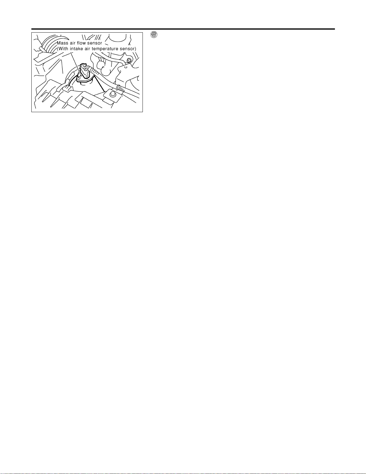
SEC055D
WITH GST
NFEC0917S02
1) Start engine and warm it up to normal operating temperature.
2) Turn ignition switch “OFF” and wait at least 10 seconds.
3) Disconnect mass air flow sensor harness connector. Then
restart and run engine for at least 5 seconds at idle speed.
4) Stop engine and reconnect mass air flow sensor harness con-
nector.
5) Select “MODE 7” with GST. Make sure DTC P0102 is detected.
6) Select “MODE 4” with GST and erase the DTC P0102.
7) Start engine again and let it idle for at least 10 minutes.
8) Select “MODE 7” with GST. The 1st trip DTC P0172 or P0175
should be detected at this stage, if a malfunction exists. If so,
go to “Diagnostic Procedure”, EC-279.
9) If it is difficult to start engine at step 7, the fuel injection sys-
tem has a malfunction.
10) Crank engine while depressing accelerator pedal.
If engine starts, go to “Diagnostic Procedure”, EC-279. If
engine does not start, check exhaust and intake air leak visu-
ally.
DTC P0172, P0175 FUEL INJECTION SYSTEM FUNCTION
DTC Confirmation Procedure (Cont’d)
EC-276
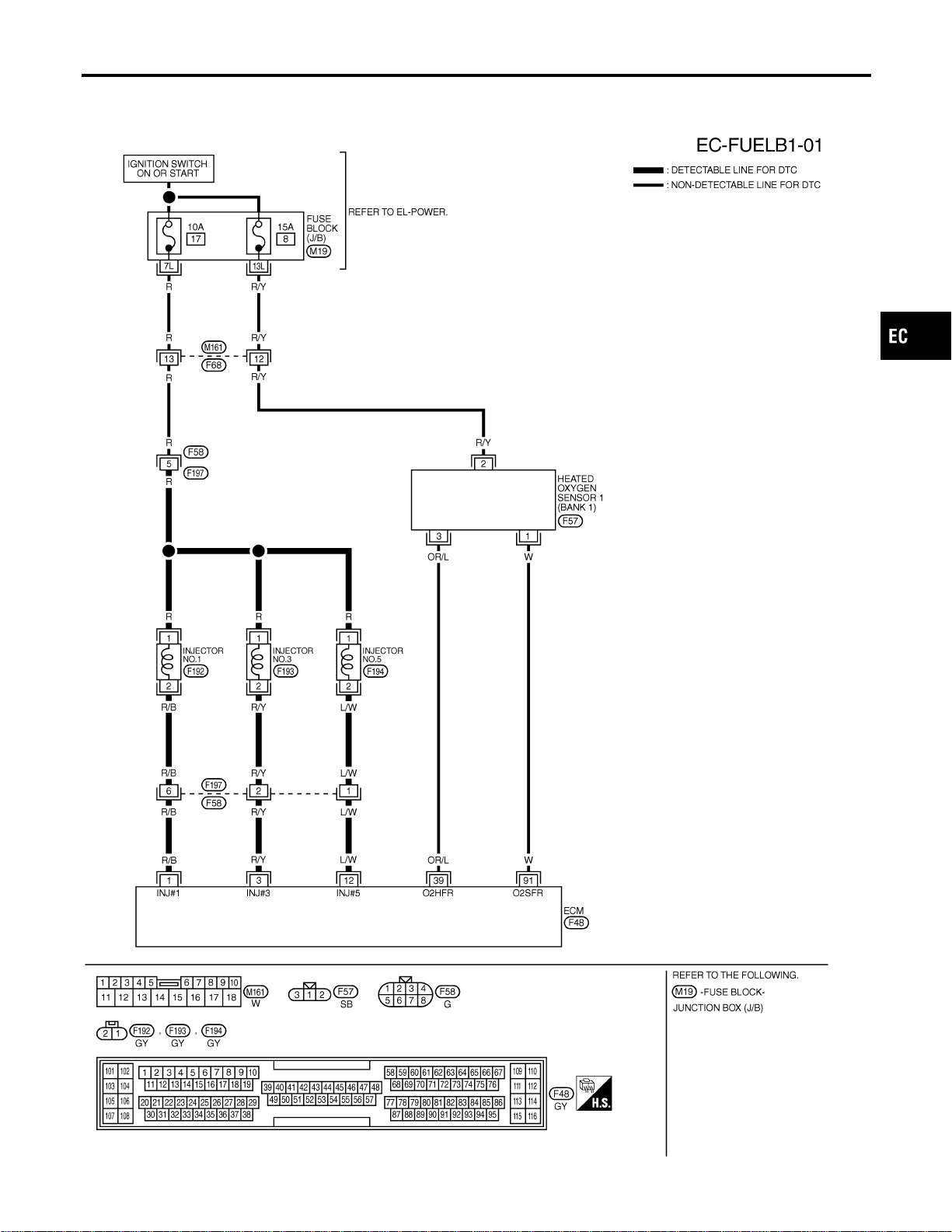
Wiring Diagram
NFEC0918
BANK 1
NFEC0918S01
MEC487D
GI
MA
EM
LC
FE
CL
MT
AT
AX
SU
BR
ST
RS
BT
HA
SC
EL
IDX
DTC P0172, P0175 FUEL INJECTION SYSTEM FUNCTION
Wiring Diagram
EC-277
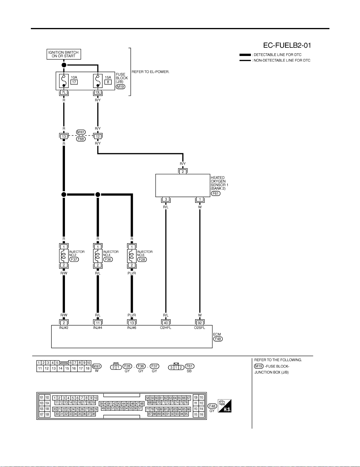
BANK 2
NFEC0918S02
MEC488D
DTC P0172, P0175 FUEL INJECTION SYSTEM FUNCTION
Wiring Diagram (Cont’d)
EC-278
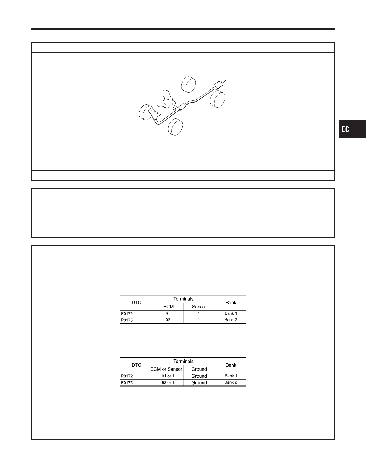
Diagnostic Procedure
NFEC0919
1 CHECK EXHAUST AIR LEAK
1. Start engine and run it at idle.
2. Listen for an exhaust air leak before three way catalyst.
SEF099P
OK or NG
OK © GO TO 2.
NG © Repair or replace.
2 CHECK FOR INTAKE AIR LEAK
Listen for an intake air leak after the mass air flow sensor.
OK or NG
OK © GO TO 3.
NG © Repair or replace.
3 CHECK HEATED OXYGEN SENSOR 1 CIRCUIT FOR OPEN AND SHORT
1. Turn ignition switch “OFF”.
2. Disconnect corresponding heated oxygen sensor 1 harness connector.
3. Disconnect ECM harness connector.
4. Check harness continuity between ECM terminal and HO2S1 terminal as follows.
Refer to Wiring Diagram.
MTBL1156
Continuity should exist.
5. Check harness continuity between ECM terminal or HO2S1 terminal and ground as follows.
Refer to Wiring Diagram.
MTBL1157
Continuity should not exist.
6. Also check harness for short to power.
OK or NG
OK © GO TO 4.
NG © Repair open circuit or short to ground or short to power in harness or connectors.
GI
MA
EM
LC
FE
CL
MT
AT
AX
SU
BR
ST
RS
BT
HA
SC
EL
IDX
DTC P0172, P0175 FUEL INJECTION SYSTEM FUNCTION
Diagnostic Procedure
EC-279
4 CHECK FUEL PRESSURE
1. Release fuel pressure to zero. Refer to EC-56.
2. Install fuel pressure gauge and check fuel pressure. Refer to EC-56.
At idling:
Approximately 350 kPa (3.7 kg/cm
2
, 51 psi)
OK or NG
OK © GO TO 5.
NG © Follow the construction of “Fuel Pressure Check”, EC-56.
5 CHECK MASS AIR FLOW SENSOR
With CONSULT-II
1. Install all removed parts.
2. Check “MASS AIR FLOW” in “DATA MONITOR” mode with CONSULT-II.
2.0 - 6.0 g·m/sec: at idling
7.0 - 20.0 g·m/sec: at 2,500 rpm
With GST
1. Install all removed parts.
2. Check mass air flow sensor signal in MODE 1 with GST.
2.0 - 6.0 g·m/sec: at idling
7.0 - 20.0 g·m/sec: at 2,500 rpm
OK or NG
OK © GO TO 6.
NG © Check connectors for rusted terminals or loose connections in the mass air flow sensor
circuit or engine grounds. Refer to EC-198.
DTC P0172, P0175 FUEL INJECTION SYSTEM FUNCTION
Diagnostic Procedure (Cont’d)
EC-280
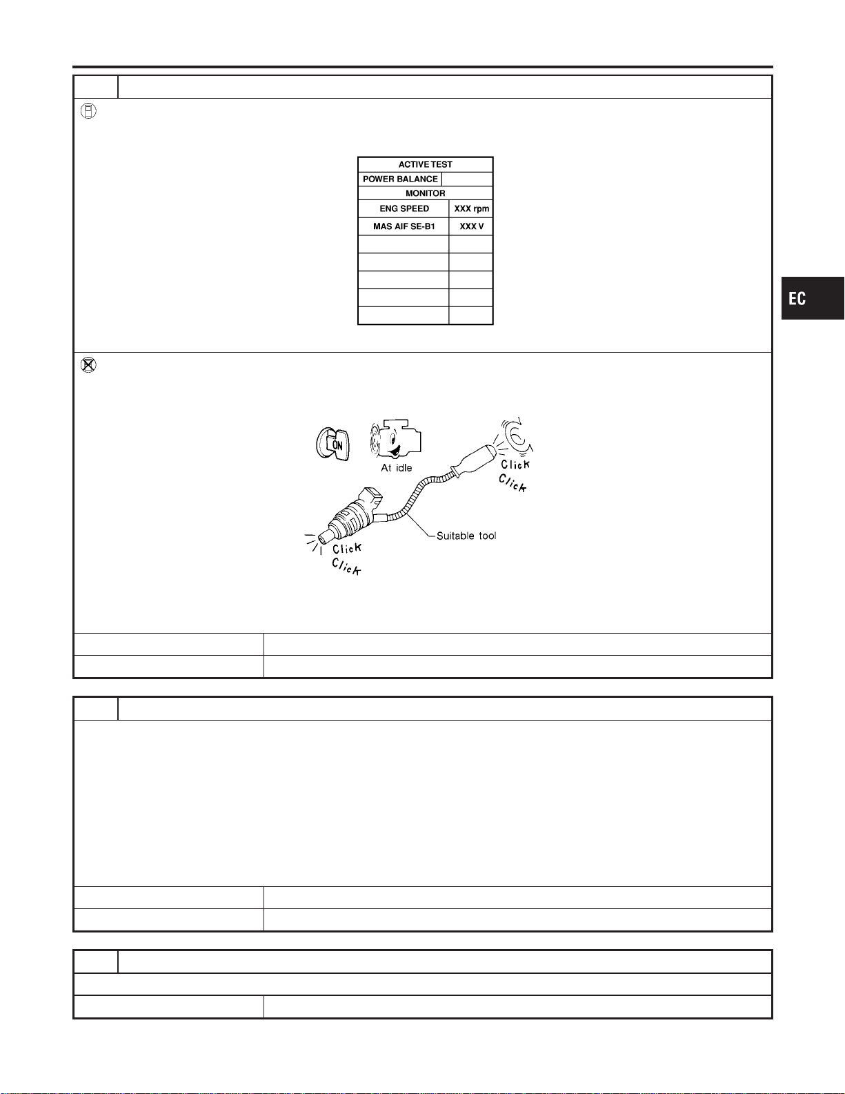
6 CHECK FUNCTION OF INJECTORS
With CONSULT-II
1. Start engine.
2. Perform “POWER BALANCE” in “ACTIVE TEST” mode with CONSULT-II.
SEC136D
3. Make sure that each circuit produces a momentary engine speed drop.
Without CONSULT-II
1. Start engine.
2. Listen to each injector operating sound.
MEC703B
Clicking noise should be heard.
OK or NG
OK © GO TO 7.
NG © Perform trouble diagnosis for “INJECTORS”, EC-703.
7 CHECK INJECTOR
1. Remove injector assembly. Refer to EC-57.
Keep fuel hose and all injectors connected to injector gallery.
2. Confirm that the engine is cooled down and there are no fire hazards near the vehicle.
3. Disconnect injector harness connectors bank 2 (for DTC P0172), bank 1 (for P0175).
The injector harness connectors on bank 1 (for P0172), bank 2 (for P0175) should remain connected.
4. Disconnect all ignition coil harness connectors.
5. Prepare pans or saucers under each injectors.
6. Crank engine for about 3 seconds.
Make sure fuel does not drip from injector.
OK or NG
OK (Does not drip.) © GO TO 8.
NG (Drips.) © Replace the injectors from which fuel is dripping. Always replace O-ring with new one.
8 CHECK INTERMITTENT INCIDENT
Refer to “TROUBLE DIAGNOSIS FOR INTERMITTENT INCIDENT”, EC-156.
© INSPECTION END
GI
MA
EM
LC
FE
CL
MT
AT
AX
SU
BR
ST
RS
BT
HA
SC
EL
IDX
DTC P0172, P0175 FUEL INJECTION SYSTEM FUNCTION
Diagnostic Procedure (Cont’d)
EC-281
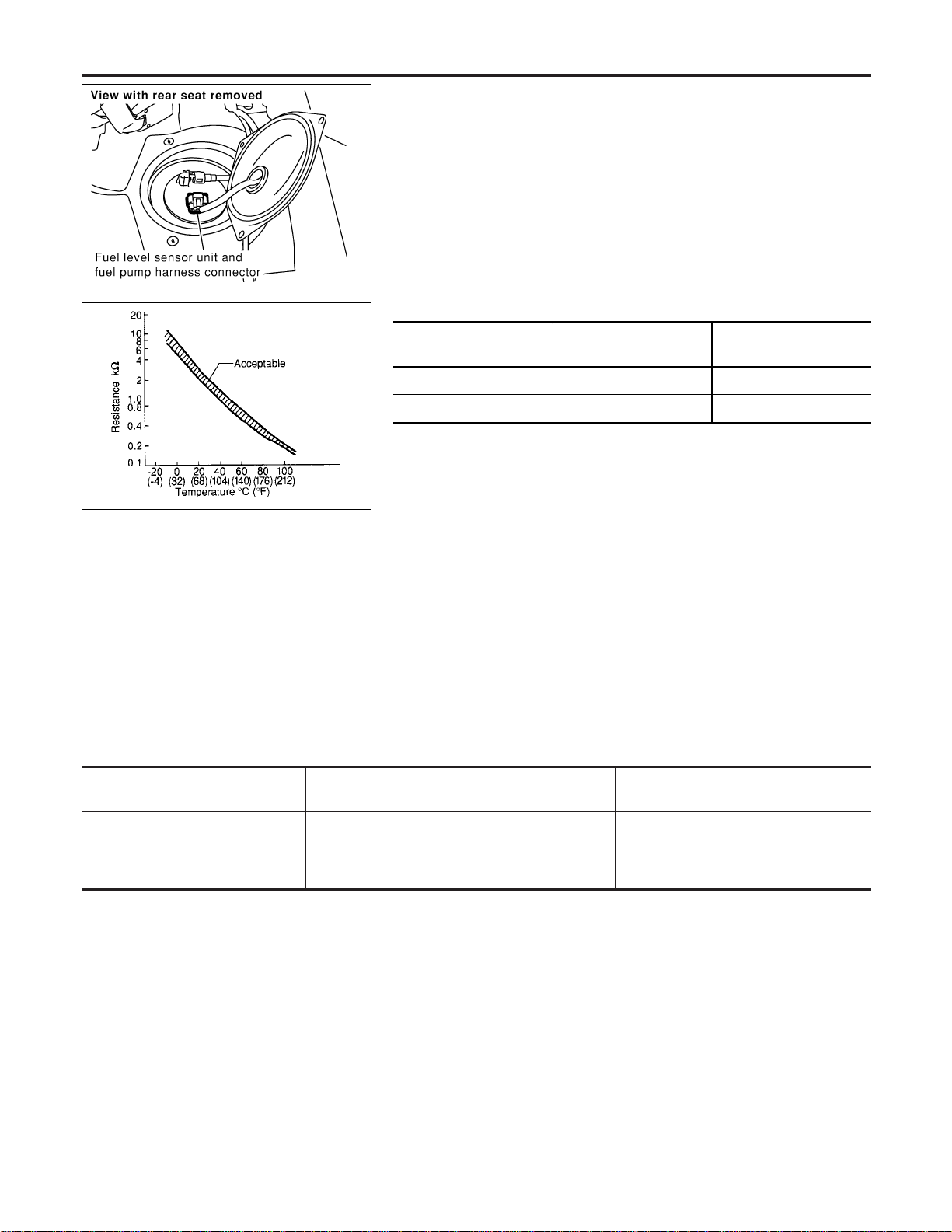
SEC082D
Component Description
NFEC0773
The fuel tank temperature sensor is used to detect the fuel tem-
perature inside the fuel tank. The sensor modifies a voltage signal
from the ECM. The modified signal returns to the ECM as the fuel
temperature input. The sensor uses a thermistor which is sensitive
to the change in temperature. The electrical resistance of the ther-
mistor decreases as temperature increases.
SEF012P
<Reference data>
Fuel temperature
°C (°F)
Voltage* V Resistance kΩ
20 (68) 3.5 2.3 - 2.7
50 (122) 2.2 0.79 - 0.90
*: These data are reference values and are measured between ECM terminal 75
(Fuel tank temperature sensor) and body ground.
CAUTION:
Do not use ECM ground terminals when measuring input/
output voltage. Doing so may result in damage to the ECM’s
transistor. Use a ground other than ECM terminals, such as
the ground.
On Board Diagnosis Logic
NFEC0774
DTC No.
Trouble diagnosis
name
DTC Detecting Condition Possible Cause
P0181
0181
Fuel tank temperature
sensor circuit range/
performance
Rationally incorrect voltage from the sensor is sent
to ECM, compared with the voltage signals from
engine coolant temperature sensor and intake air
temperature sensor.
I Harness or connectors
(The sensor circuit is open or
shorted.)
I Fuel tank temperature sensor
DTC Confirmation Procedure
NFEC0776
NOTE:
If “DTC Confirmation Procedure” has been previously conducted,
always turn ignition switch “OFF” and wait at least 10 seconds
before conducting the next test.
DTC P0181 FTT SENSOR
Component Description
EC-282
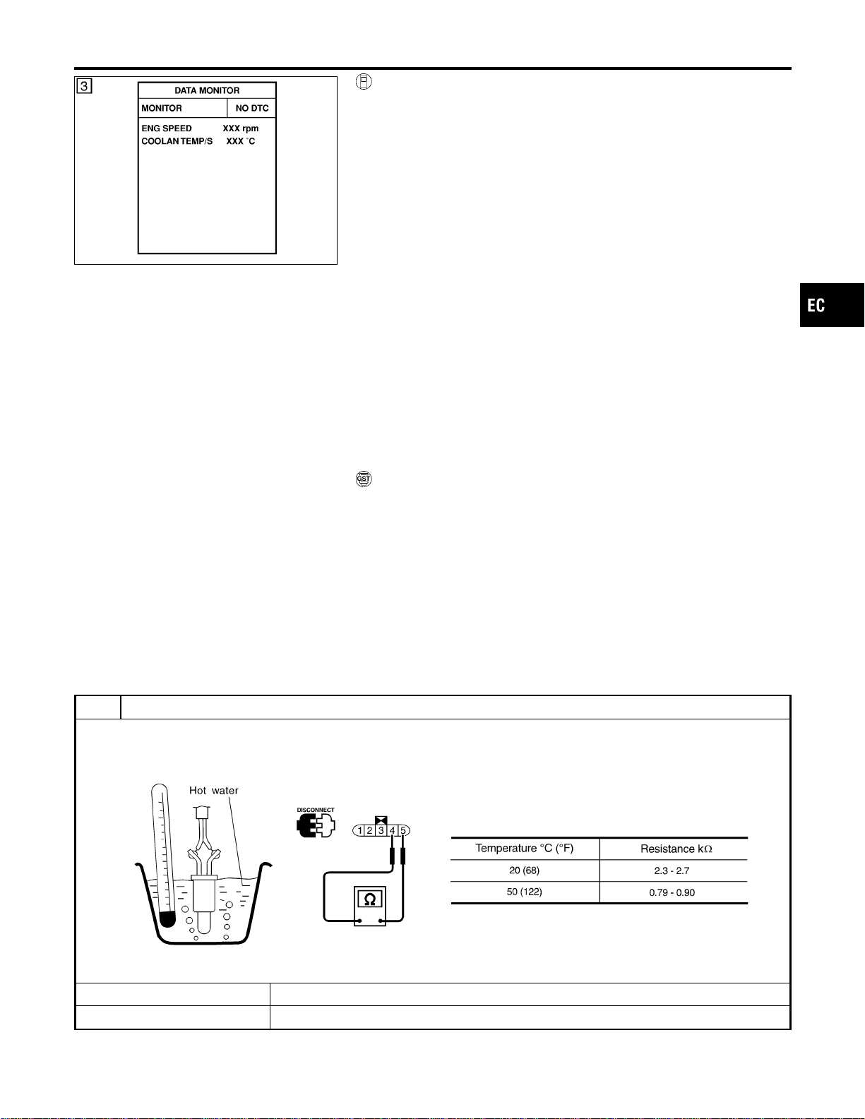
SEF174Y
WITH CONSULT-II
NFEC0776S01
1) Turn ignition switch “ON”.
2) Select “DATA MONITOR” mode with CONSULT-II.
3) Wait at least 10 seconds.
If the result is NG, go to “Diagnostic Procedure”, EC-283.
If the result is OK, go to following step.
4) Check “COOLAN TEMP/S” value.
If “COOLAN TEMP/S” is less than 60°C (140°F), the result will
be OK.
If “COOLAN TEMP/S” is above 60°C (140°F), go to the follow-
ing step.
5) Cool engine down until “COOLAN TEMP/S” is less than 60°C
(140°F).
6) Wait at least 10 seconds.
7) If 1st trip DTC is detected, go to “Diagnostic Procedure”,
EC-283.
WITH GST
NFEC0776S02
Follow the procedure “With CONSULT-II” above.
Diagnostic Procedure
NFEC0778
1 CHECK FUEL TANK TEMPERATURE SENSOR
1. Remove fuel level sensor unit.
2. Check resistance between fuel level sensor unit and fuel pump terminals 4 and 5 by heating with hot water or heat gun
as shown in the figure.
SEF587X
OK or NG
OK © GO TO 2.
NG © Replace fuel level sensor unit.
GI
MA
EM
LC
FE
CL
MT
AT
AX
SU
BR
ST
RS
BT
HA
SC
EL
IDX
DTC P0181 FTT SENSOR
DTC Confirmation Procedure (Cont’d)
EC-283

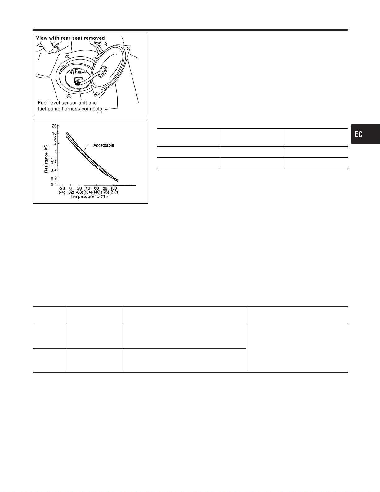
SEC082D
Component Description
NFEC0920
The fuel tank temperature sensor is used to detect the fuel tem-
perature inside the fuel tank. The sensor modifies a voltage signal
from the ECM. The modified signal returns to the ECM as the fuel
temperature input. The sensor uses a thermistor which is sensitive
to the change in temperature. The electrical resistance of the ther-
mistor decreases as temperature increases.
SEF012P
<Reference data>
Fuel temperature
°C (°F)
Voltage* V Resistance kΩ
20 (68) 3.5 2.3 - 2.7
50 (122) 2.2 0.79 - 0.90
*: These data are reference values and are measured between ECM terminal 75
(Fuel tank temperature sensor) and body ground.
CAUTION:
Do not use ECM ground terminals when measuring input/
output voltage. Doing so may result in damage to the ECM’s
transistor. Use a ground other than ECM terminals, such as
the ground.
On Board Diagnosis Logic
NFEC0921
DTC No.
Trouble diagnosis
name
DTC Detecting Condition Possible Cause
P0182
0182
Fuel tank temperature
sensor circuit low
input
An excessively low voltage from the sensor is sent
to ECM.
I Harness or connectors
(The sensor circuit is open or
shorted.)
I Fuel tank temperature sensor
P0183
0183
Fuel tank temperature
sensor circuit high
input
An excessively high voltage from the sensor is
sent to ECM.
DTC Confirmation Procedure
NFEC0922
NOTE:
If “DTC Confirmation Procedure” has been previously conducted,
always turn ignition switch “OFF” and wait at least 10 seconds
before conducting the next test.
GI
MA
EM
LC
FE
CL
MT
AT
AX
SU
BR
ST
RS
BT
HA
SC
EL
IDX
DTC P0182, P0183 FTT SENSOR
Component Description
EC-285
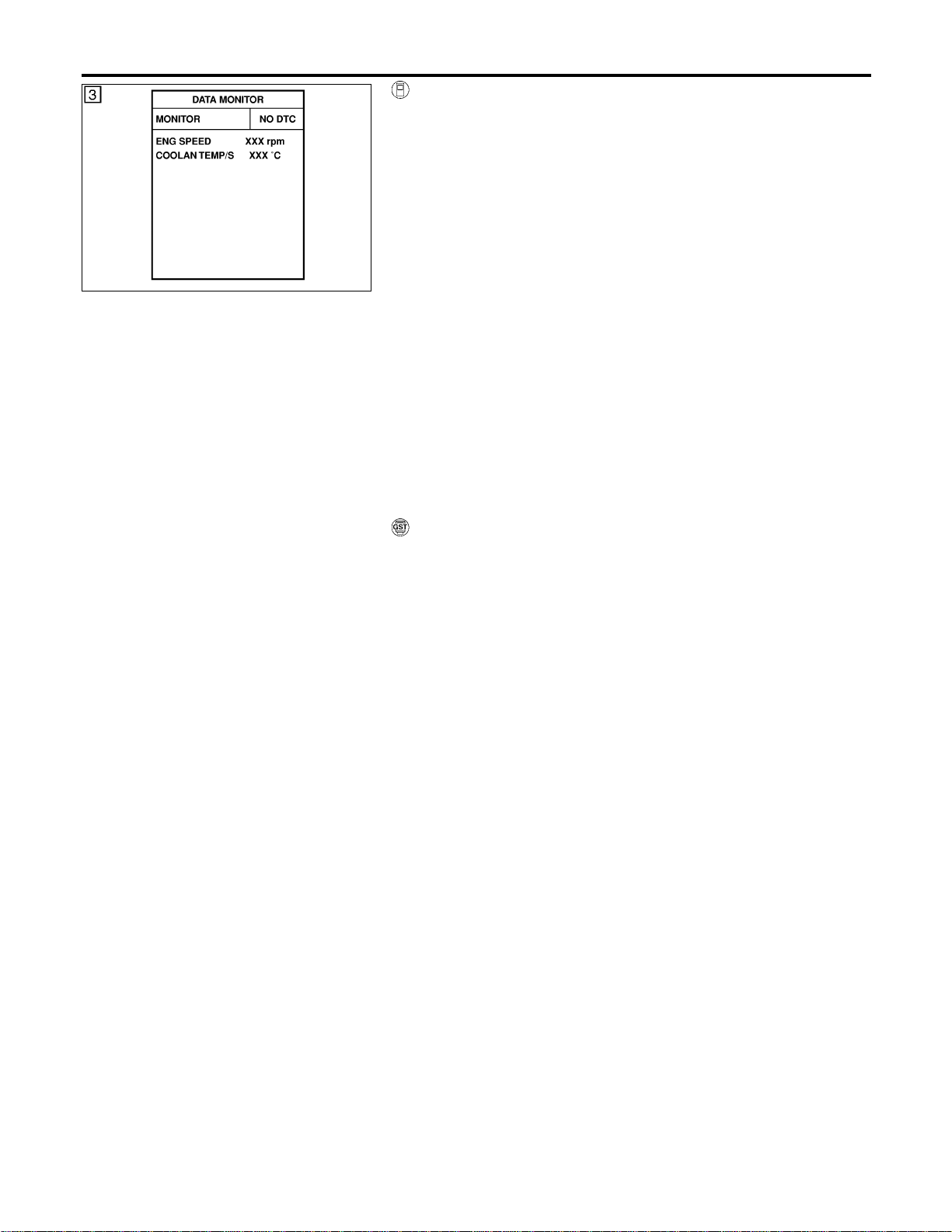
SEF174Y
WITH CONSULT-II
NFEC0922S01
1) Turn ignition switch “ON”.
2) Select “DATA MONITOR” mode with CONSULT-II.
3) Wait at least 10 seconds.
If the result is NG, go to “Diagnostic Procedure”, EC-288.
If the result is OK, go to following step.
4) Check “COOLAN TEMP/S” value.
If “COOLAN TEMP/S” is less than 60°C (140°F), the result will
be OK.
If “COOLAN TEMP/S” is above 60°C (140°F), go to the follow-
ing step.
5) Cool engine down until “COOLAN TEMP/S” is less than 60°C
(140°F).
6) Wait at least 10 seconds.
7) If 1st trip DTC is detected, go to “Diagnostic Procedure”,
EC-288.
WITH GST
NFEC0922S02
Follow the procedure “With CONSULT-II” above.
DTC P0182, P0183 FTT SENSOR
DTC Confirmation Procedure (Cont’d)
EC-286

Wiring Diagram
NFEC0923
MEC489D
GI
MA
EM
LC
FE
CL
MT
AT
AX
SU
BR
ST
RS
BT
HA
SC
EL
IDX
DTC P0182, P0183 FTT SENSOR
Wiring Diagram
EC-287
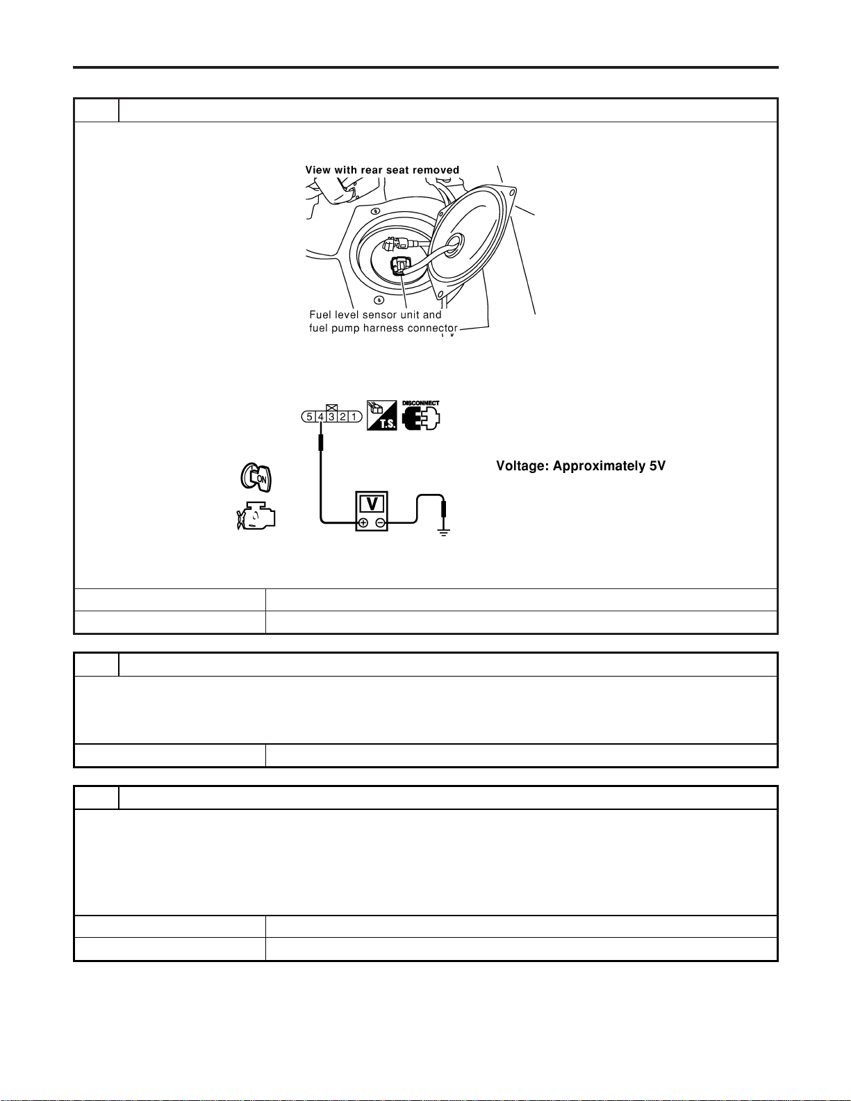
Diagnostic Procedure
NFEC0924
1 CHECK FUEL TANK TEMPERATURE SENSOR POWER SUPPLY CIRCUIT
1. Turn ignition switch “OFF”.
2. Disconnect fuel level sensor unit and fuel pump harness connector.
SEC082D
3. Turn ignition switch “ON”.
4. Check voltage between fuel level sensor unit terminal 4 and ground with CONSULT-II or tester.
SEC116D
OK or NG
OK © GO TO 3.
NG © GO TO 2.
2 DETECT MALFUNCTIONING PART
Check the following.
I Harness connectors B3, M6
I Harness connectors M81, F49
I Harness for open or short between ECM and fuel level sensor unit and fuel pump
© Repair harness or connector.
3 CHECK FUEL TANK TEMPERATURE SENSOR GROUND CIRCUIT FOR OPEN AND SHORT
1. Turn ignition switch “OFF”.
2. Check harness continuity between fuel level sensor unit and fuel pump terminal 5 and body ground. Refer to Wiring
Diagram.
Continuity should exist.
3. Also check harness for short to power.
OK or NG
OK © GO TO 4.
NG © Repair open circuit or short to power in harness or connectors.
DTC P0182, P0183 FTT SENSOR
Diagnostic Procedure
EC-288
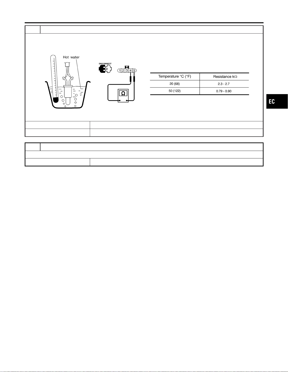
4 CHECK FUEL TANK TEMPERATURE SENSOR
1. Remove fuel level sensor unit.
2. Check resistance between fuel level sensor unit and fuel pump terminals 4 and 5 by heating with hot water or heat gun
as shown in the figure.
SEF587X
OK or NG
OK © GO TO 5.
NG © Replace fuel level sensor unit.
5 CHECK INTERMITTENT INCIDENT
Refer to “TROUBLE DIAGNOSIS FOR INTERMITTENT INCIDENT”, EC-156.
© INSPECTION END
GI
MA
EM
LC
FE
CL
MT
AT
AX
SU
BR
ST
RS
BT
HA
SC
EL
IDX
DTC P0182, P0183 FTT SENSOR
Diagnostic Procedure (Cont’d)
EC-289
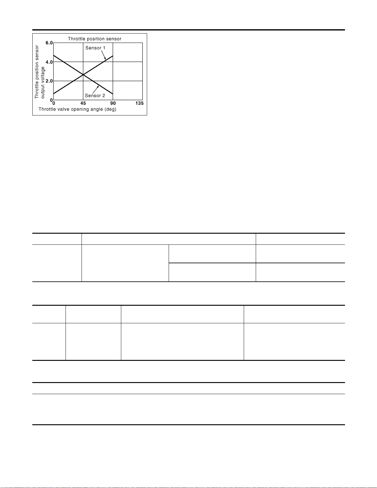
PBIB0145E
Component Description
NFEC1365
Electric Throttle Control Actuator Consists of throttle control motor,
throttle position sensor, etc. The throttle position sensor responds
to the throttle vale movement.
The throttle position sensor has the two sensors. These sensors
are a kind of potentiometers which transform the throttle valve
position into output voltage, and emit the voltage signal to the ECM.
In addition, these sensors detect the opening and closing speed of
the throttle valve and feed the voltage signals to the ECM. The
ECM judges the current opening angle of the throttle valve form
these signal and the ECM controls the throttle control motor to
make the throttle valve opening angle properly in response to driv-
ing condition.
CONSULT-II Reference Value in Data Monitor
Mode
NFEC1366
Specification data are reference values.
MONITOR ITEM CONDITION SPECIFICATION
THRTL SEN1
THRTL SEN2
I Ignition switch:
ON (Engine stopped)
I Shift lever:
D (A/T model)
1st (M/T model)
Accelerator pedal: Fully released More than 0.36V
Accelerator pedal: Fully depressed Less than 4.75V
On Board Diagnosis Logic
NFEC1434
This self-diagnosis has the one trip detection logic.
DTC No.
Trouble diagnosis
name
DTC Detecting Condition Possible Cause
P0221
0221
Throttle position sen-
sor circuit range/
performance problem
Rationally incorrect voltage is sent to ECM com-
pared with the signals from TP sensor 1 and TP
sensor 2.
I Harness or connector
(The TP sensor 1 and 2 circuit is
open or shorted.)
I Electric throttle control actuator (TP
sensor 1 and 2)
FAIL-SAFE MODE
NFEC1434S01
When the malfunction is detected, the ECM enters in fail-safe mode and the MIL lights up.
Engine operation condition in fail-safe mode
The ECM controls the electric throttle control actuator in regulating the throttle opening in order for the idle position to be within
+10 degrees.
The ECM regulates an opening speed of approx. 5 seconds to an opening of 10 degrees.
So, the acceleration will be poor.
DTC P0221 TP SENSOR
Component Description
EC-290
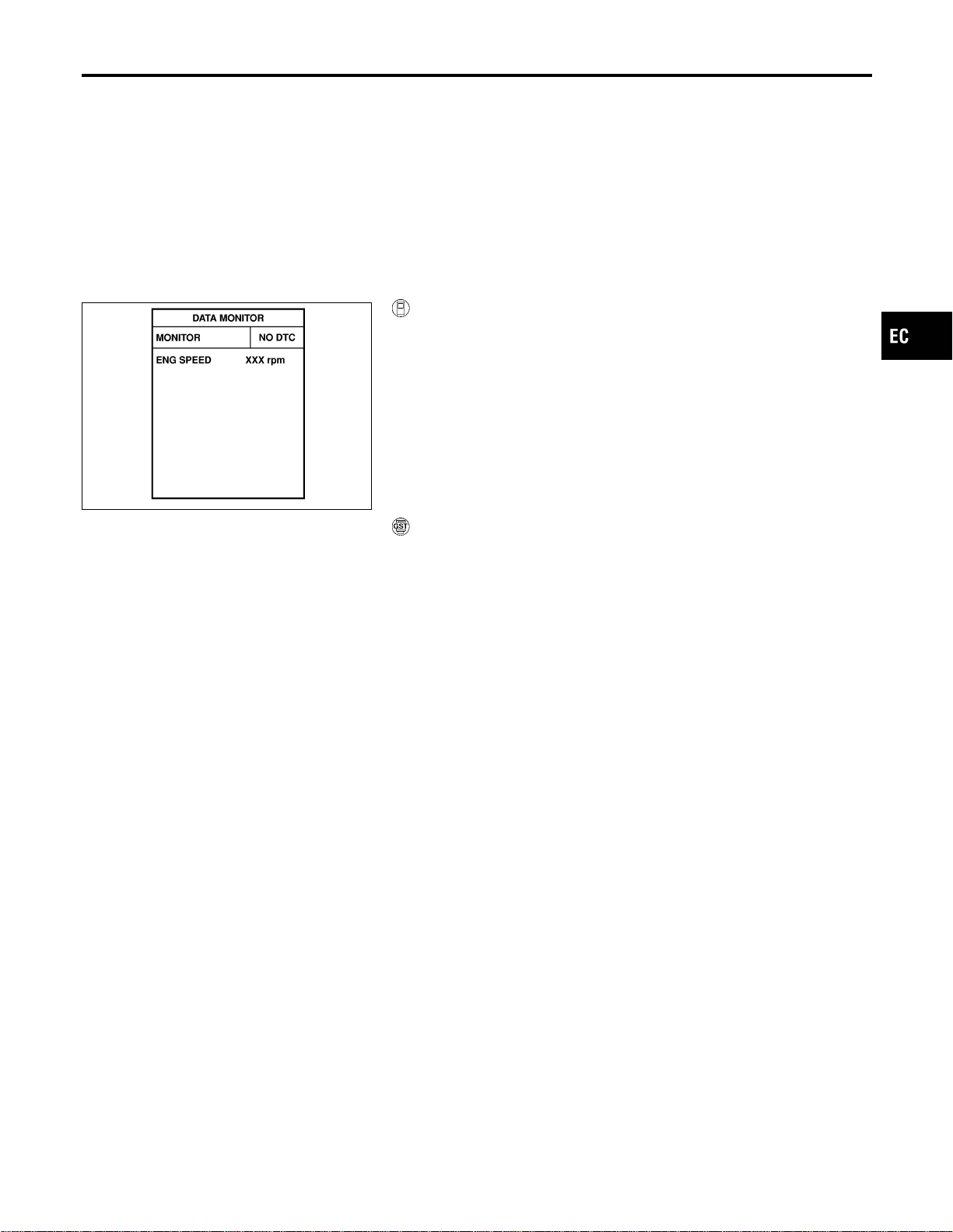
DTC Confirmation Procedure
NFEC1435
NOTE:
If “DTC Confirmation Procedure” has been previously conducted,
always turn ignition switch “OFF” and wait at least 10 seconds
before conducting the next test.
TESTING CONDITION:
Before performing the following procedure, confirm that bat-
tery voltage is more than 10V at idle.
SEF058Y
With CONSULT-II
1. Turn ignition switch “ON”.
2. Select “DATA MONITOR” mode with CONSULT-II.
3. Start engine and let it idle for 1 second.
4. If DTC is detected, go to “Diagnostic Procedure”, EC-293.
With GST
Follow the procedure “WITH CONSULT-II” above.
GI
MA
EM
LC
FE
CL
MT
AT
AX
SU
BR
ST
RS
BT
HA
SC
EL
IDX
DTC P0221 TP SENSOR
DTC Confirmation Procedure
EC-291
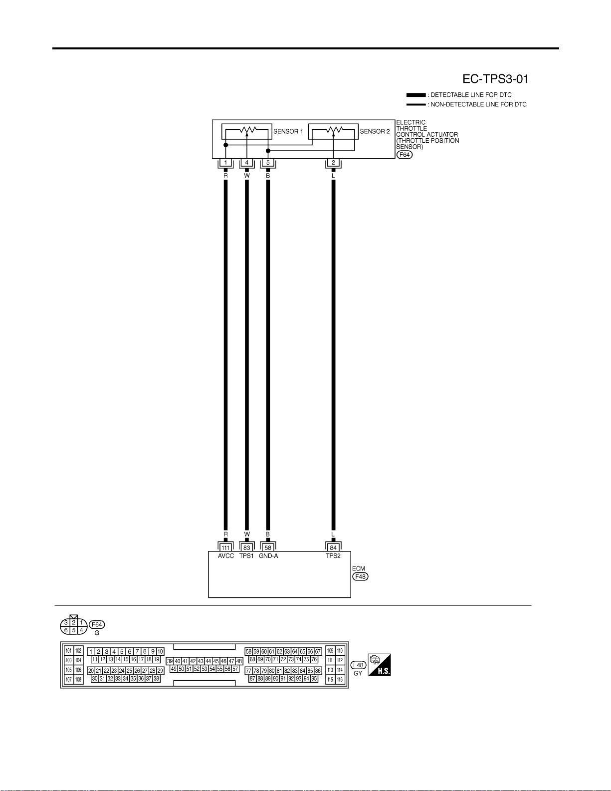
Wiring Diagram
NFEC1369
MEC476D
DTC P0221 TP SENSOR
Wiring Diagram
EC-292
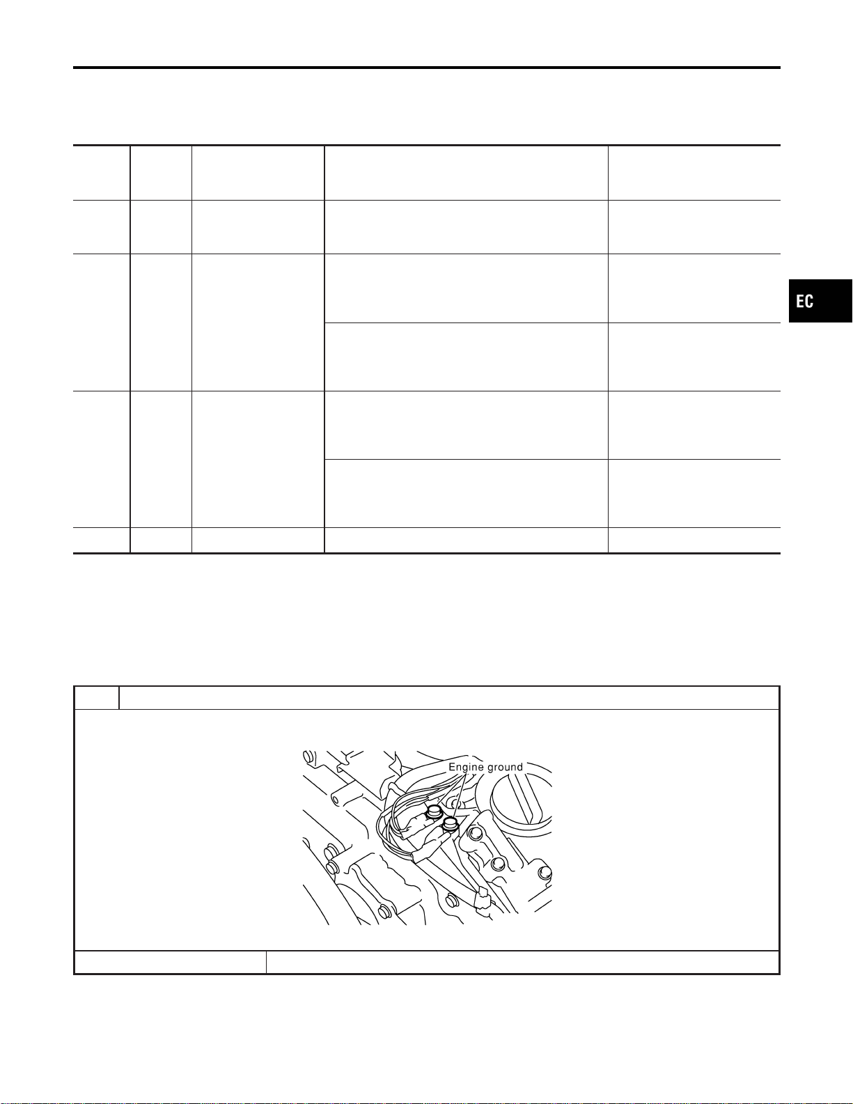
Specification data are reference values and are measured between each terminal and ground.
CAUTION:
Do not use ECM ground terminals when measuring input/output voltage. Doing so may result in dam-
age to the ECM’s transistor. Use a ground other than ECM terminals, such as the ground.
TERMI-
NAL
NO.
WIRE
COLOR
ITEM CONDITION DATA (DC Voltage)
58 B Sensors’ ground
[Engine is running]
I Warm-up condition
I Idle speed
Approximately 0V
83 W
Throttle position sensor
1
[Ignition switch “ON”]
I Shift lever position is “D” (A/T model)
I Shift lever position is “1st” (M/T model)
I Accelerator pedal fully released
More than 0.36V
[Ignition switch “ON”]
I Shift lever position is “D” (A/T model)
I Shift lever position is “1st” (M/T model)
I Accelerator pedal fully depressed
Less than 4.75V
84 L
Throttle position sensor
2
[Ignition switch “ON”]
I Shift lever position is “D” (A/T model)
I Shift lever position is “1st” (M/T model)
I Accelerator pedal fully released
Less than 4.75V
[Ignition switch “ON”]
I Shift lever position is “D” (A/T model)
I Shift lever position is “1st” (M/T model)
I Accelerator pedal fully depressed
More than 0.36V
111 R Sensor’s power supply [Ignition switch “ON”] Approximately 5V
Diagnostic Procedure
NFEC1370
1 RETIGHTEN GROUND SCREWS
1. Turn ignition switch “OFF”.
2. Loosen and retighten engine ground screws.
SEC047D
© GO TO 2.
GI
MA
EM
LC
FE
CL
MT
AT
AX
SU
BR
ST
RS
BT
HA
SC
EL
IDX
DTC P0221 TP SENSOR
Wiring Diagram (Cont’d)
EC-293
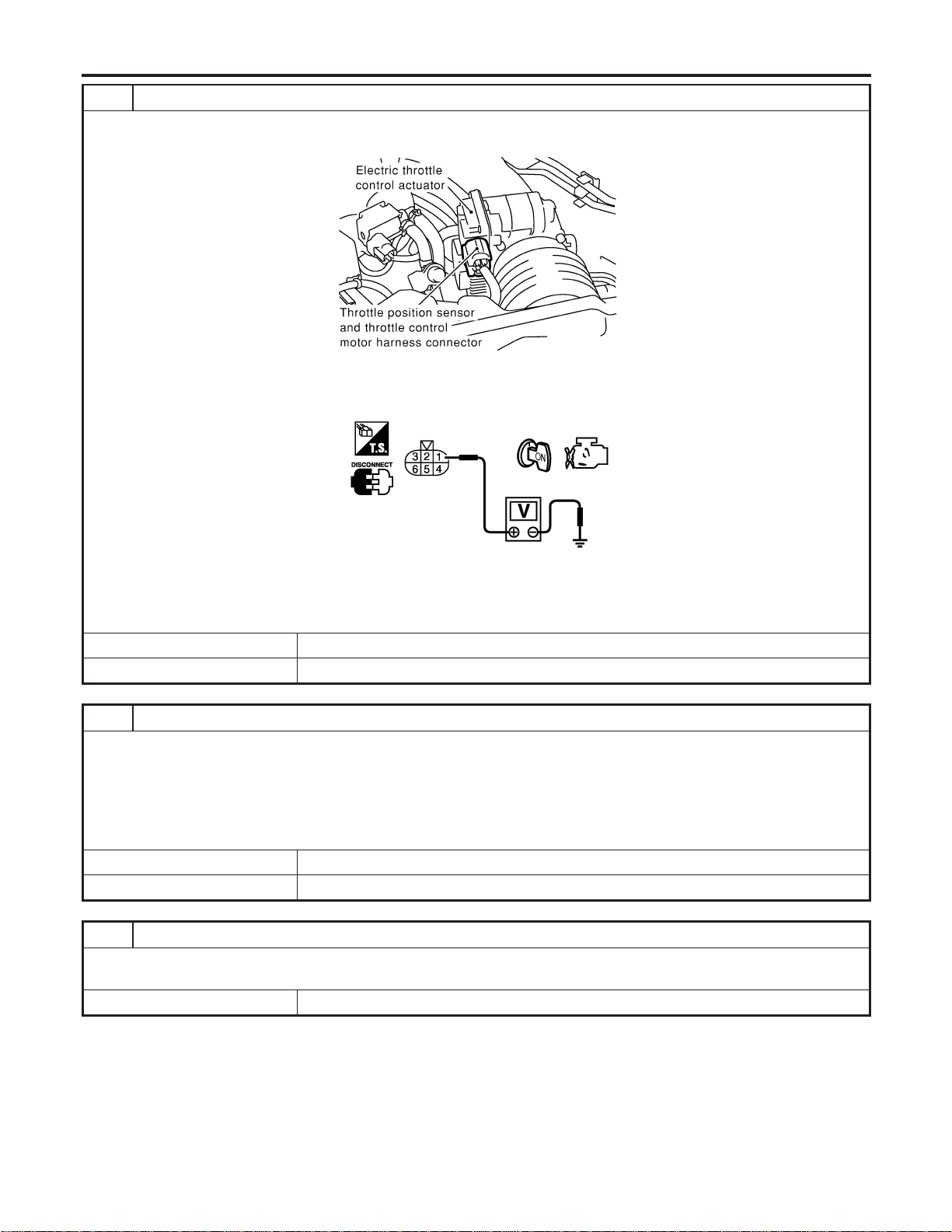
2 CHECK THROTTLE POSITION SENSOR POWER SUPPLY CIRCUIT
1. Disconnect electric throttle control actuator harness connector.
2. Turn ignition switch “ON”.
SEC054D
3. Check voltage between electric throttle control actuator terminal 1 and ground with CONSULT-II or tester.
PBIB0082E
Voltage: Approximately 5V
OK or NG
OK © GO TO 3.
NG © Repair open circuit or short to ground or short to power in harness or connectors.
3 CHECK THROTTLE POSITION SENSOR GROUND CIRCUIT FOR OPEN AND SHORT
1. Turn ignition switch “OFF”.
2. Check harness continuity between electric throttle control actuator terminal 5 and engine ground.
Refer to Wiring Diagram.
Continuity should exist.
3. Also check harness for short to ground and short to power.
OK or NG
OK © GO TO 5.
NG © GO TO 4.
4 DETECT MALFUNCTIONING PART
Check the following.
I Harness for open or short between electric throttle control actuator and ECM
© Repair open circuit or short to ground or short to power in harness or connectors.
DTC P0221 TP SENSOR
Diagnostic Procedure (Cont’d)
EC-294
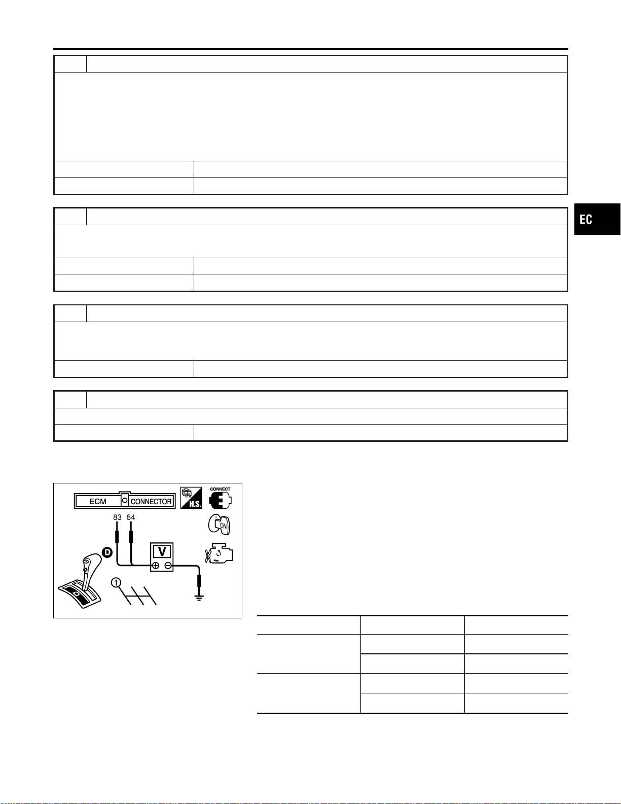
5 CHECK THROTTLE POSITION SENSOR INPUT SIGNAL CIRCUIT FOR OPEN AND SHORT
1. Disconnect ECM harness connector.
2. Check harness continuity between ECM terminal 83 and electric throttle control actuator terminal 4, ECM terminal 84
and electric throttle control actuator terminal 2.
Refer to Wiring Diagram.
Continuity should exist.
3. Also check harness for short to ground and short to power.
OK or NG
OK © GO TO 6.
NG © Repair open circuit or short to ground or short to power in harness or connectors.
6 CHECK THROTTLE POSITION SENSOR
Refer to “Component Inspection”, EC-295.
OK or NG
OK © GO TO 8.
NG © GO TO 7.
7 REPLACE ELECTRIC THROTTLE CONTROL ACTUATOR
1. Replace the electric throttle control actuator.
2. Perform “Throttle Valve Closed Position Learning”, EC-71.
3. Perform “Idle Air Volume Learning”, EC-71.
© INSPECTION END
8 CHECK INTERMITTENT INCIDENT
Refer to “TROUBLE DIAGNOSIS FOR INTERMITTENT INCIDENT”, EC-156.
© INSPECTION END
SEC900C
Component Inspection
NFEC1371
THROTTLE POSITION SENSOR
1. Reconnect all harness connectors disconnected.
2. Perform “Throttle Valve Closed Position Learning”, EC-71.
3. Turn ignition switch “ON”.
4. Set selector lever to “D” position (A/T models) or “1st” position
(M/T models).
5. Check voltage between ECM terminals 83 (TP sensor 1), 84
(TP sensor 2) and engine ground under the following condi-
tions.
Terminal Accelerator pedal Voltage
83
(Throttle position sensor
1)
Fully released More than 0.36V
Fully depressed Less than 4.75V
84
(Throttle position sensor
2)
Fully released Less than 4.75V
Fully depressed More than 0.36V
6. If NG, replace electric throttle control actuator and go to the
next step.
7. Perform “Throttle Valve Closed Position Learning”, EC-71.
GI
MA
EM
LC
FE
CL
MT
AT
AX
SU
BR
ST
RS
BT
HA
SC
EL
IDX
DTC P0221 TP SENSOR
Diagnostic Procedure (Cont’d)
EC-295

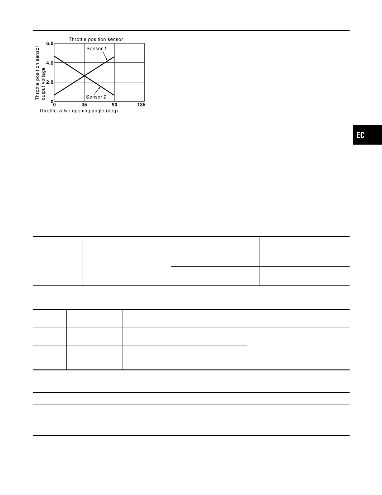
PBIB0145E
Component Description
NFEC1372
Electric Throttle Control Actuator consists of throttle control motor,
throttle position sensor, etc. The throttle position sensor responds
to the throttle valve movement.
The throttle position sensor has the two sensors. These sensors
are a kind of potentiometers which transform the throttle valve
position into output voltage, and emit the voltage signal to the ECM.
In addition, these sensors detect the opening and closing speed of
the throttle valve and feed the voltage signals to the ECM. The
ECM judges the current opening angle of the throttle valve from
these signals and the ECM controls the throttle control motor to
make the throttle valve opening angle properly in response to driv-
ing condition.
CONSULT-II Reference Value in Data Monitor
Mode
NFEC1373
Specification data are reference values.
MONITOR ITEM CONDITION SPECIFICATION
THRTL SEN1
I Ignition switch:
ON (Engine stopped)
I Shift lever:
D (A/T model)
1st (M/T model)
Accelerator pedal: Fully released More than 0.36V
Accelerator pedal: Fully depressed Less than 4.75V
On Board Diagnosis Logic
NFEC1436
These self-diagnoses have the one trip detection logic.
DTC No.
Trouble diagnosis
name
DTC Detecting Condition Possible Cause
P0222
0222
Throttle position sen-
sor 1 circuit low input
An excessively low voltage from the TP sensor 1
is sent to ECM.
I Harness or connectors
(The TP sensor 1 circuit is open or
shorted.)
I Electric throttle control actuator (TP
sensor 1)
P0223
0223
Throttle position sen-
sor 1 circuit high
input
An excessively high voltage from the TP sensor 1
is sent to ECM.
FAIL-SAFE MODE
NFEC1436S01
When the malfunction is detected, ECM enters in fail-safe mode and the MIL lights up.
Engine operation condition in fail-safe mode
The ECM controls the electric throttle control actuator in regulating the throttle opening in order for the idle position to be within
+10 degrees.
The ECM regulates an opening speed of approx. 5 seconds to an opening of 10 degrees.
So, the acceleration will be poor.
GI
MA
EM
LC
FE
CL
MT
AT
AX
SU
BR
ST
RS
BT
HA
SC
EL
IDX
DTC P0222, P0223 TP SENSOR
Component Description
EC-297
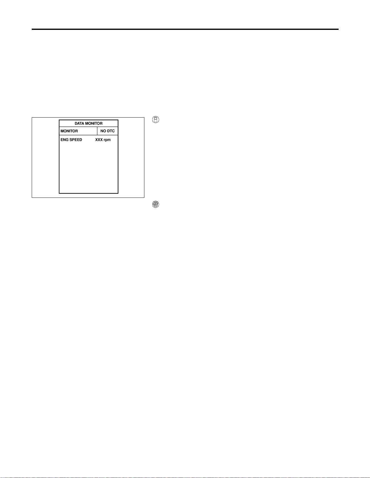
DTC Confirmation Procedure
NFEC1437
NOTE:
If “DTC Confirmation Procedure” has been previously conducted,
always turn ignition switch “OFF” and wait at least 10 seconds
before conducting the next test.
TESTING CONDITION:
Before performing the following procedure, confirm that bat-
tery voltage is more than 10V at idle.
SEF058Y
With CONSULT-II
1. Turn ignition switch “ON”.
2. Select “DATA MONITOR” mode with CONSULT-II.
3. Start engine and let it idle for 1 second.
4. If DTC is detected, go to “Diagnostic Procedure”, EC-300.
With GST
Follow the procedure “WITH CONSULT-II” above.
DTC P0222, P0223 TP SENSOR
DTC Confirmation Procedure
EC-298
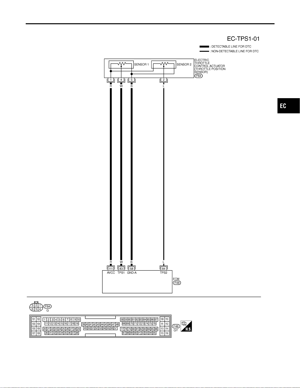
Wiring Diagram
NFEC1376
MEC700D
GI
MA
EM
LC
FE
CL
MT
AT
AX
SU
BR
ST
RS
BT
HA
SC
EL
IDX
DTC P0222, P0223 TP SENSOR
Wiring Diagram
EC-299
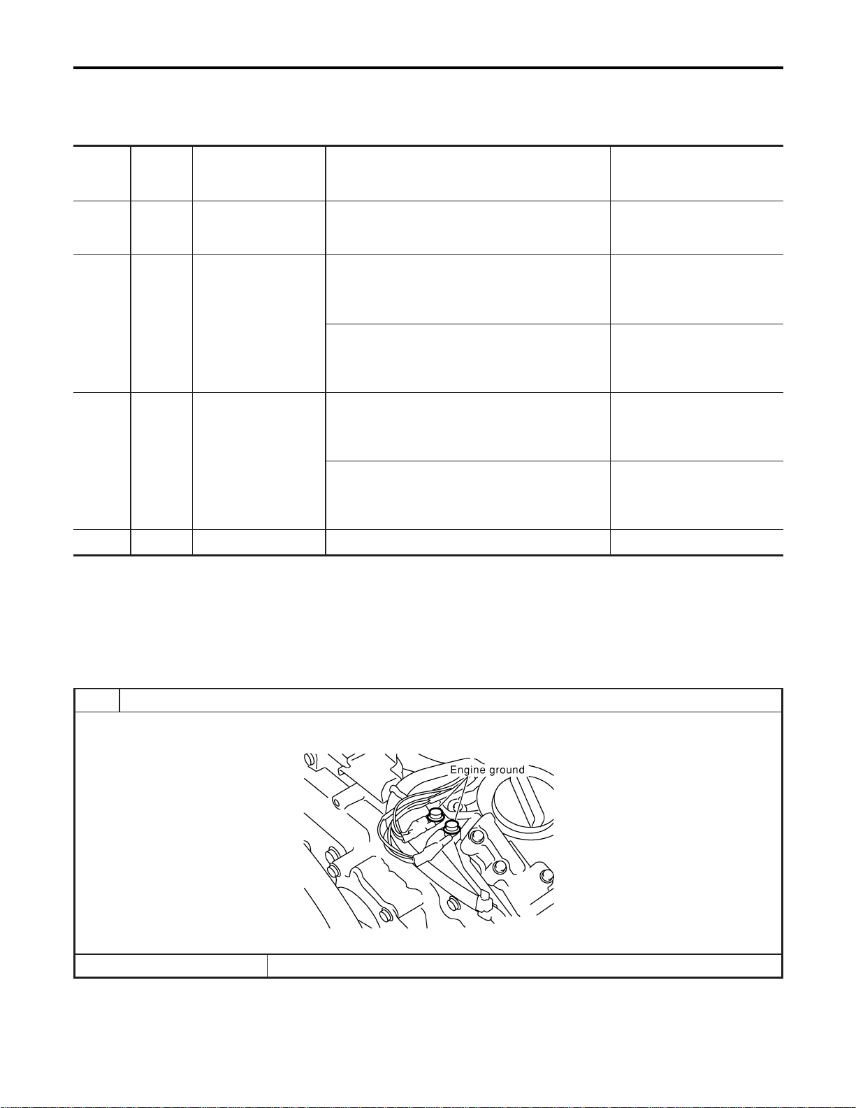
Specification data are reference values and are measured between each terminal and ground.
CAUTION:
Do not use ECM ground terminals when measuring input/output voltage. Doing so may result in dam-
age to the ECM’s transistor. Use a ground other than ECM terminals, such as the ground.
TERMI-
NAL
NO.
WIRE
COLOR
ITEM CONDITION DATA (DC Voltage)
58 B Sensors’ ground
[Engine is running]
I Warm-up condition
I Idle speed
Approximately 0V
83 W
Throttle position sensor
1
[Ignition switch “ON”]
I Shift lever position is “D” (A/T model)
I Shift lever position is “1st” (M/T model)
I Accelerator pedal fully released
More than 0.36V
[Ignition switch “ON”]
I Shift lever position is “D” (A/T model)
I Shift lever position is “1st” (M/T model)
I Accelerator pedal fully depressed
Less than 4.75V
84 L
Throttle position sensor
2
[Ignition switch “ON”]
I Shift lever position is “D” (A/T model)
I Shift lever position is “1st” (M/T model)
I Accelerator pedal fully released
Less than 4.75V
[Ignition switch “ON”]
I Shift lever position is “D” (A/T model)
I Shift lever position is “1st” (M/T model)
I Accelerator pedal fully depressed
More than 0.36V
111 R Sensor’s power supply [Ignition switch “ON”] Approximately 5V
Diagnostic Procedure
NFEC1377
1 RETIGHTEN GROUND SCREWS
1. Turn ignition switch “OFF”.
2. Loosen and retighten engine ground screws.
SEC047D
© GO TO 2.
DTC P0222, P0223 TP SENSOR
Wiring Diagram (Cont’d)
EC-300
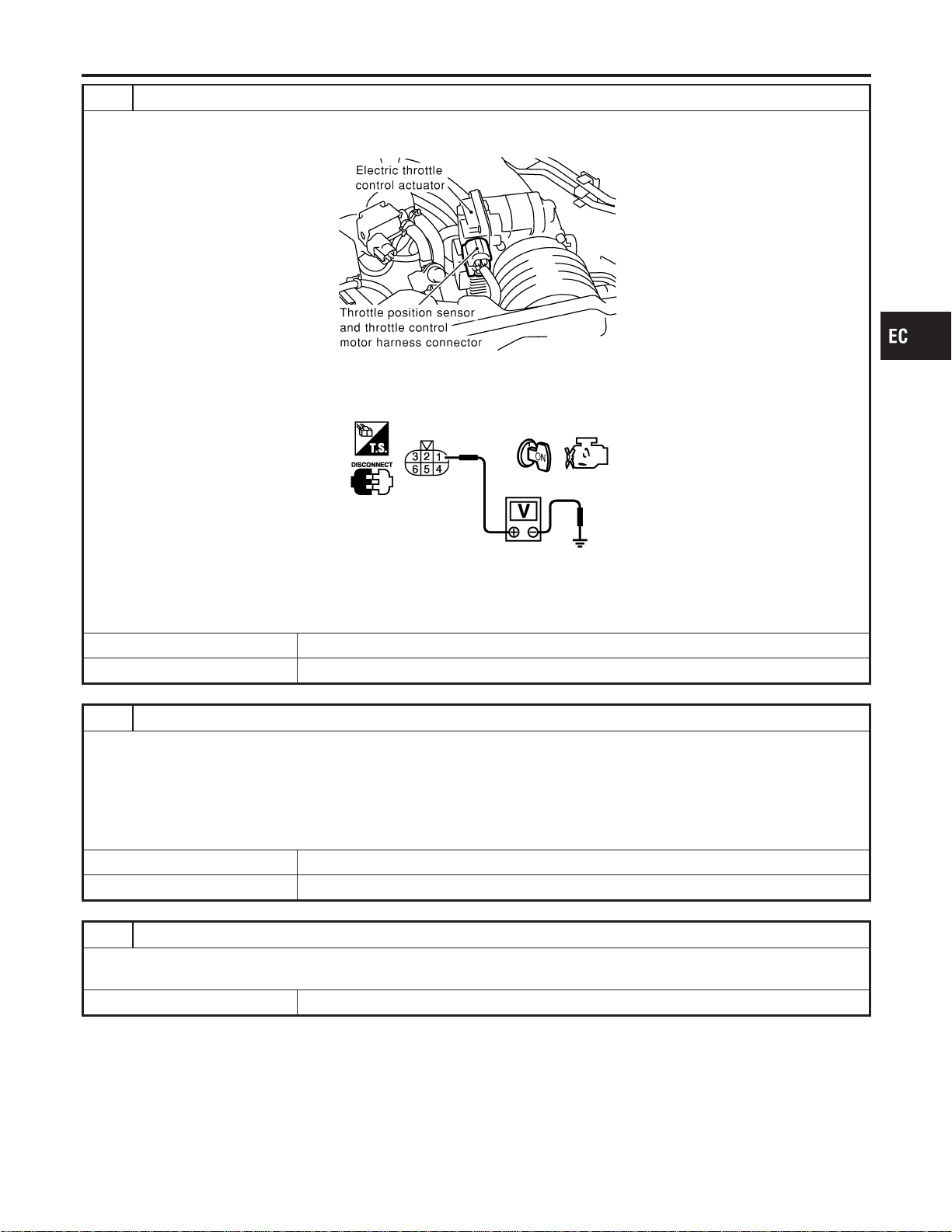
2 CHECK THROTTLE POSITION SENSOR 1 POWER SUPPLY CIRCUIT
1. Disconnect electric throttle control actuator harness connector.
2. Turn ignition switch “ON”.
SEC054D
3. Check voltage between electric throttle control actuator terminal 1 and ground with CONSULT-II or tester.
PBIB0082E
Voltage: Approximately 5V
OK or NG
OK © GO TO 3.
NG © Repair open circuit or short to ground or short to power in harness or connectors.
3 CHECK THROTTLE POSITION SENSOR 1 GROUND CIRCUIT FOR OPEN AND SHORT
1. Turn ignition switch “OFF”.
2. Check harness continuity between electric throttle control actuator terminal 5 and engine ground.
Refer to Wiring Diagram.
Continuity should exist.
3. Also check harness for short to ground and short to power.
OK or NG
OK © GO TO 5.
NG © GO TO 4.
4 DETECT MALFUNCTIONING PART
Check the following.
I Harness for open or short between electric throttle control actuator and ECM
© Repair open circuit or short to ground or short to power in harness or connectors.
GI
MA
EM
LC
FE
CL
MT
AT
AX
SU
BR
ST
RS
BT
HA
SC
EL
IDX
DTC P0222, P0223 TP SENSOR
Diagnostic Procedure (Cont’d)
EC-301
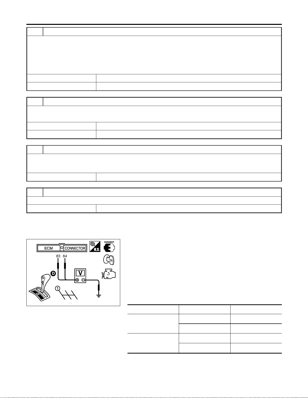
5 CHECK THROTTLE POSITION SENSOR 1 INPUT SIGNAL CIRCUIT FOR OPEN AND SHORT
1. Disconnect ECM harness connector.
2. Check harness continuity between ECM terminal 83 and electric throttle control actuator terminal 4.
Refer to Wiring Diagram.
Continuity should exist.
3. Also check harness for short to ground and short to power.
OK or NG
OK © GO TO 6.
NG © Repair open circuit or short to ground or short to power in harness or connectors.
6 CHECK THROTTLE POSITION SENSOR
Refer to “Component Inspection”, EC-302.
OK or NG
OK © GO TO 8.
NG © GO TO 7.
7 REPLACE ELECTRIC THROTTLE CONTROL ACTUATOR
1. Replace the electric throttle control actuator.
2. Perform “Throttle Valve Closed Position Learning”, EC-71.
3. Perform “Idle Air Volume Learning”, EC-71.
© INSPECTION END
8 CHECK INTERMITTENT INCIDENT
Refer to “TROUBLE DIAGNOSIS FOR INTERMITTENT INCIDENT”, EC-156.
© INSPECTION END
SEC900C
Component Inspection
NFEC1378
THROTTLE POSITION SENSOR
1. Reconnect all harness connectors disconnected.
2. Perform “Throttle Valve Closed Position Learning”, EC-71.
3. Turn ignition switch “ON”.
4. Set selector lever to “D” position (A/T models) or “1st” position
(M/T models).
5. Check voltage between ECM terminals 83 (TP sensor 1), 84
(TP sensor 2) and engine ground under the following condi-
tions.
Terminal Accelerator pedal Voltage
83
(Throttle position sensor
1)
Fully released More than 0.36V
Fully depressed Less than 4.75V
84
(Throttle position sensor
2)
Fully released Less than 4.75V
Fully depressed More than 0.36V
6. If NG, replace electric throttle control actuator and go to the
next step.
7. Perform “Throttle Valve Closed Position Learning”, EC-71.
DTC P0222, P0223 TP SENSOR
Diagnostic Procedure (Cont’d)
EC-302

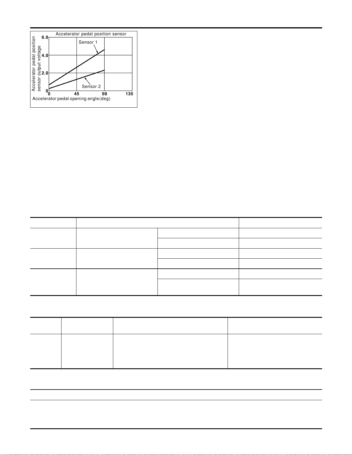
PBIB0146E
Component Description
NFEC1379
The accelerator pedal position sensor is installed on the upper end
of the accelerator pedal assembly. The sensor detects the accel-
erator position and sends a signal to the ECM.
Accelerator pedal position sensor has two sensors. These sensors
are a kind of potentiometers which transform the accelerator pedal
position into output voltage, and emit the voltage signal to the ECM.
In addition, these sensors detect the opening and closing speed of
the accelerator pedal and feed the voltage signals to the ECM. The
ECM judges the current opening angle of the accelerator pedal
from these signals and controls the throttle control motor based on
these signals.
Idle position of the accelerator pedal is determined by the ECM
receiving the signal from the accelerator pedal position sensor. The
ECM uses this signal for the engine operation such as fuel cut.
CONSULT-II Reference Value in Data Monitor
Mode
NFEC1380
Specification data are reference values.
MONITOR ITEM CONDITION SPECIFICATION
ACCEL SEN1
I Ignition switch: ON
(engine stopped)
Accelerator pedal: Fully released 0.41 - 0.71V
Accelerator pedal: Fully depressed More than 3.7V
ACCEL SEN2
I Ignition switch: ON
(engine stopped)
Accelerator pedal: Fully released 0.15 - 0.97V
Accelerator pedal: Fully depressed More than 3.5V
CLSD THL POS I Ignition switch: ON
Accelerator pedal: Fully released ON
Accelerator pedal: Slightly
depressed
OFF
On Board Diagnosis Logic
NFEC1438
This self-diagnosis has the one trip detection logic.
DTC No.
Trouble diagnosis
name
DTC Detecting Condition Possible Cause
P0226
0226
Accelerator pedal
position sensor circuit
range/performance
problem
Rationally incorrect voltage is sent to ECM com-
pared with the signals from APP sensor 1 and
APP sensor 2.
I Harness or connector
(The APP sensor 1 and 2 circuit is
open or shorted.)
I Accelerator pedal position sensor 1
and 2
FAIL-SAFE MODE
NFEC1438S01
When the malfunction is detected, ECM enters in fail-safe mode and the MIL lights up.
Engine operation condition in fail-safe mode
The ECM controls the electric throttle control actuator in regulating the throttle opening in order for the idle position to be within
+10 degrees.
The ECM regulates an opening speed of approx. 5 seconds to an opening of 10 degrees.
So, the acceleration will be poor.
DTC P0226 APP SENSOR
Component Description
EC-304
DTC Confirmation Procedure
NFEC1439
NOTE:
If “DTC Confirmation Procedure” has been previously conducted,
always turn ignition switch “OFF” and wait at least 10 seconds
before conducting the next test.
TESTING CONDITION:
Before performing the following procedure, confirm that bat-
tery voltage is more than 10V at idle.
SEF058Y
With CONSULT-II
1. Turn ignition switch “ON”.
2. Select “DATA MONITOR” mode with CONSULT-II.
3. Start engine and let it idle for 1 second.
4. If DTC is detected, go to “Diagnostic Procedure”, EC-307.
With GST
Follow the procedure “WITH CONSULT-II” above.
GI
MA
EM
LC
FE
CL
MT
AT
AX
SU
BR
ST
RS
BT
HA
SC
EL
IDX
DTC P0226 APP SENSOR
DTC Confirmation Procedure
EC-305
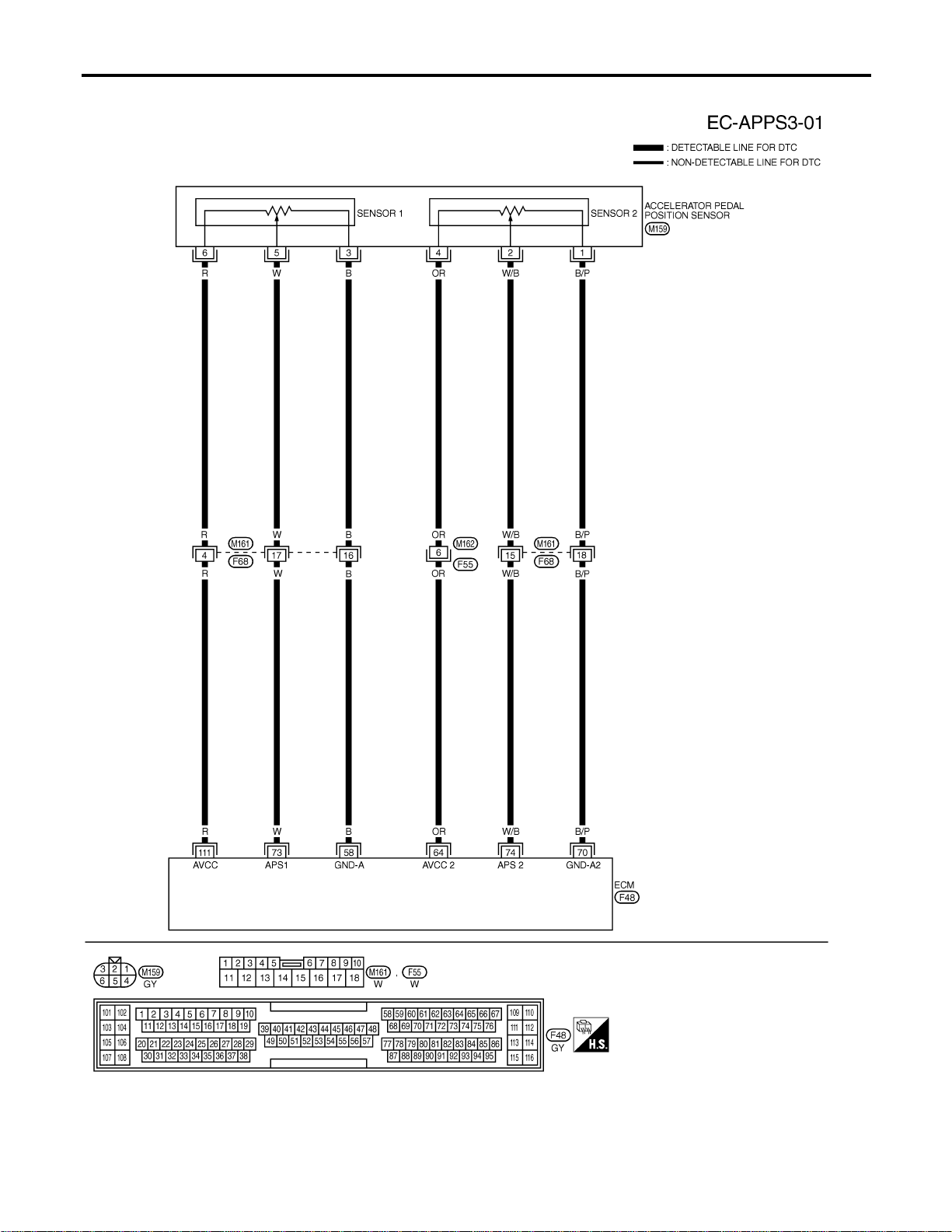
Wiring Diagram
NFEC1383
MEC925D
DTC P0226 APP SENSOR
Wiring Diagram
EC-306
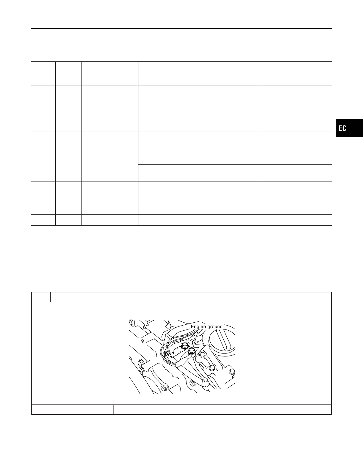
Specification data are reference values and are measured between each terminal and ground.
CAUTION:
Do not use ECM ground terminals when measuring input/output voltage. Doing so may result in dam-
age to the ECM’s transistor. Use a ground other than ECM terminals, such as the ground.
TERMI-
NAL
NO.
WIRE
COLOR
ITEM CONDITION DATA (DC Voltage)
58 B Sensors’ ground
[Engine is running]
I Warm-up condition
I Idle speed
Approximately 0V
64 OR
Accelerator pedal posi-
tion sensor 2 power
supply
[Ignition switch “ON”] Approximately 2.5V
70 B/P
Accelerator pedal posi-
tion sensor 2 ground
[Ignition switch “ON”] Approximately 0V
73 W
Accelerator pedal posi-
tion sensor 1
[Ignition switch “ON”]
I Accelerator pedal fully released
0.41 - 0.71V
[Ignition switch “ON”]
I Accelerator pedal fully depressed
More than 3.7V
74 W/B
Accelerator pedal posi-
tion sensor 2
[Ignition switch “ON”]
I Accelerator pedal fully released
0.08 - 0.48V
[Ignition switch “ON”]
I Accelerator pedal fully depressed
More than 1.8V
111 R Sensor’s power supply [Ignition switch “ON”] Approximately 5V
Diagnostic Procedure
NFEC1384
1 RETIGHTEN GROUND SCREWS
1. Turn ignition switch “OFF”.
2. Loosen and retighten engine ground screws.
SEC047D
© GO TO 2.
GI
MA
EM
LC
FE
CL
MT
AT
AX
SU
BR
ST
RS
BT
HA
SC
EL
IDX
DTC P0226 APP SENSOR
Wiring Diagram (Cont’d)
EC-307
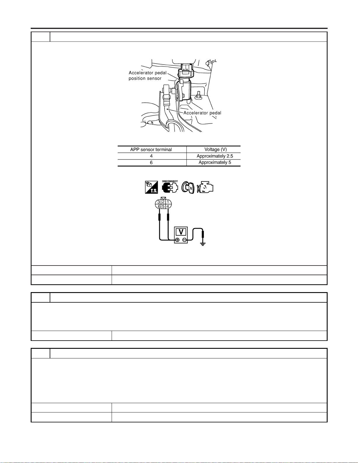
2 CHECK APP SENSOR POWER SUPPLY CIRCUIT
1. Disconnect accelerator pedal position (APP) sensor harness connector.
2. Turn ignition switch “ON”.
SEC081D
3. Check voltage between APP sensor terminals 4, 6 and ground with CONSULT-II or tester.
MTBL1167
SEC092D
OK or NG
OK © GO TO 4.
NG © GO TO 3.
3 DETECT MALFUNCTIONING PART
Check the following.
I Harness connectors M161, F68
I Harness connectors M162, F55
I Harness for open or short between ECM and accelerator pedal position sensor
OK © Repair open circuit or short to ground or short to power in harness or connectors.
4 CHECK APP SENSOR GROUND CIRCUIT FOR OPEN AND SHORT
1. Turn ignition switch “OFF”.
2. Check harness continuity between APP sensor terminals 1, 3 and engine ground.
Refer to Wiring Diagram.
Continuity should exist.
3. Also check harness for short to ground and short to power.
OK or NG
OK © GO TO 6.
NG © GO TO 5.
DTC P0226 APP SENSOR
Diagnostic Procedure (Cont’d)
EC-308
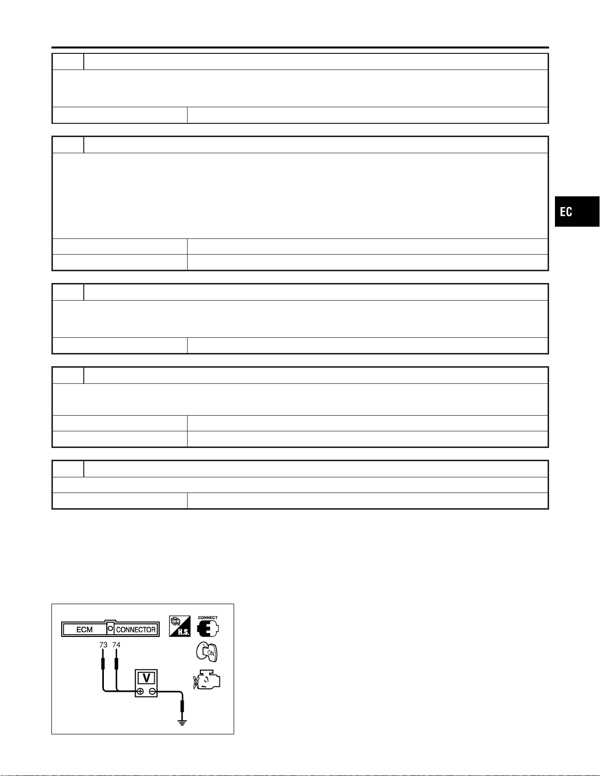
5 DETECT MALFUNCTIONING PART
Check the following.
I Harness connectors M161, F68
I Harness for open or short between ECM and accelerator pedal position sensor
© Repair open circuit or short to ground or short to power in harness or connectors.
6 CHECK APP SENSOR INPUT SIGNAL CIRCUIT FOR OPEN AND SHORT
1. Disconnect ECM harness connector.
2. Check harness continuity between ECM terminal 73 and APP sensor terminal 5, ECM terminal 74 and APP sensor ter-
minal 2.
Refer to Wiring Diagram
Continuity should exist.
3. Also check harness for short to ground and short to power.
OK or NG
OK © GO TO 8.
NG © GO TO 7.
7 DETECT MALFUNCTIONING PART
Check the following.
I Harness connectors M161, F68
I Harness for open or short between ECM and accelerator pedal position sensor
© Repair open circuit or short to ground or short to power in harness or connectors.
8 CHECK APP SENSOR
Refer to “Component Inspection”, EC-309.
OK or NG
OK © GO TO 9.
NG © Replace accelerator pedal assembly.
9 CHECK INTERMITTENT INCIDENT
Refer to “TROUBLE DIAGNOSIS FOR INTERMITTENT INCIDENT”, EC-156.
© IINSPECTION END
SEC901C
Component Inspection
NFEC1385
ACCELERATOR PEDAL POSITION SENSOR
1. Reconnect all harness connectors disconnected.
2. Turn ignition switch “ON”.
3. Check voltage between ECM terminals 73 (APP sensor 1
signal), 74 (APP sensor 2 signal) and engine ground under the
following conditions.
GI
MA
EM
LC
FE
CL
MT
AT
AX
SU
BR
ST
RS
BT
HA
SC
EL
IDX
DTC P0226 APP SENSOR
Diagnostic Procedure (Cont’d)
EC-309

Terminal Accelerator pedal Voltage
73
(Accelerator pedal posi-
tion sensor 1)
Fully released 0.41 - 0.71V
Fully depressed More than 3.7V
74
(Accelerator pedal posi-
tion sensor 2)
Fully released 0.08 - 0.48V
Fully depressed More than 1.8V
4. If NG, replace accelerator pedal assembly.
5. Perform “Accelerator Pedal Released Position Learning”,
EC-71.
6. Perform “Throttle Valve Closed Position Learning”, EC-71.
7. Perform “Idle Air Volume Learning”, EC-71.
DTC P0226 APP SENSOR
Component Inspection (Cont’d)
EC-310
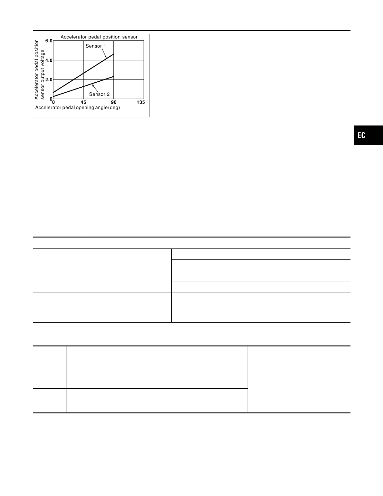
PBIB0146E
Component Description
NFEC1386
The accelerator pedal position sensor is installed on the upper end
of the accelerator pedal assembly. The sensor detects the accel-
erator position and sends a signal to the ECM.
Accelerator pedal position sensor has two sensors. These sensors
are a kind of potentiometers which transform the accelerator pedal
position into output voltage, and emit the voltage signal to the ECM.
In addition, these sensors detect the opening and closing speed of
the accelerator pedal and feed the voltage signals to the ECM. The
ECM judges the current opening angle of the accelerator pedal
from these signals and controls the throttle control motor based on
these signals.
Idle position of the accelerator pedal is determined by the ECM
receiving the signal from the accelerator pedal position sensor. The
ECM uses this signal for the engine operation such as fuel cut.
CONSULT-II Reference Value in Data Monitor
Mode
NFEC1387
Specification data are reference values.
MONITOR ITEM CONDITION SPECIFICATION
ACCEL SEN1
I Ignition switch: ON
(engine stopped)
Accelerator pedal: Fully released 0.41 - 0.71V
Accelerator pedal: Fully depressed More than 3.7V
ACCEL SEN2
I Ignition switch: ON
(engine stopped)
Accelerator pedal: Fully released 0.15 - 0.97V
Accelerator pedal: Fully depressed More than 3.5V
CLSD THL POS I Ignition switch: ON
Accelerator pedal: Fully released ON
Accelerator pedal: Slightly
depressed
OFF
On Board Diagnosis Logic
NFEC1440
These self-diagnoses have the one trip detection logic.
DTC No.
Trouble diagnosis
name
DTC Detecting Condition Possible Cause
P0227
0227
Accelerator pedal
position sensor 1 cir-
cuit low input
An excessively low voltage from the APP sensor 1
is sent to ECM.
I Harness or connectors
(The APP sensor 1 circuit is open or
shorted.)
I Accelerator pedal position sensor
(Accelerator pedal position sensor 1)
P0228
0228
Accelerator pedal
position sensor 1 cir-
cuit high input
An excessively high voltage from the APP sensor
1 is sent to ECM.
GI
MA
EM
LC
FE
CL
MT
AT
AX
SU
BR
ST
RS
BT
HA
SC
EL
IDX
DTC P0227, P0228 APP SENSOR
Component Description
EC-311
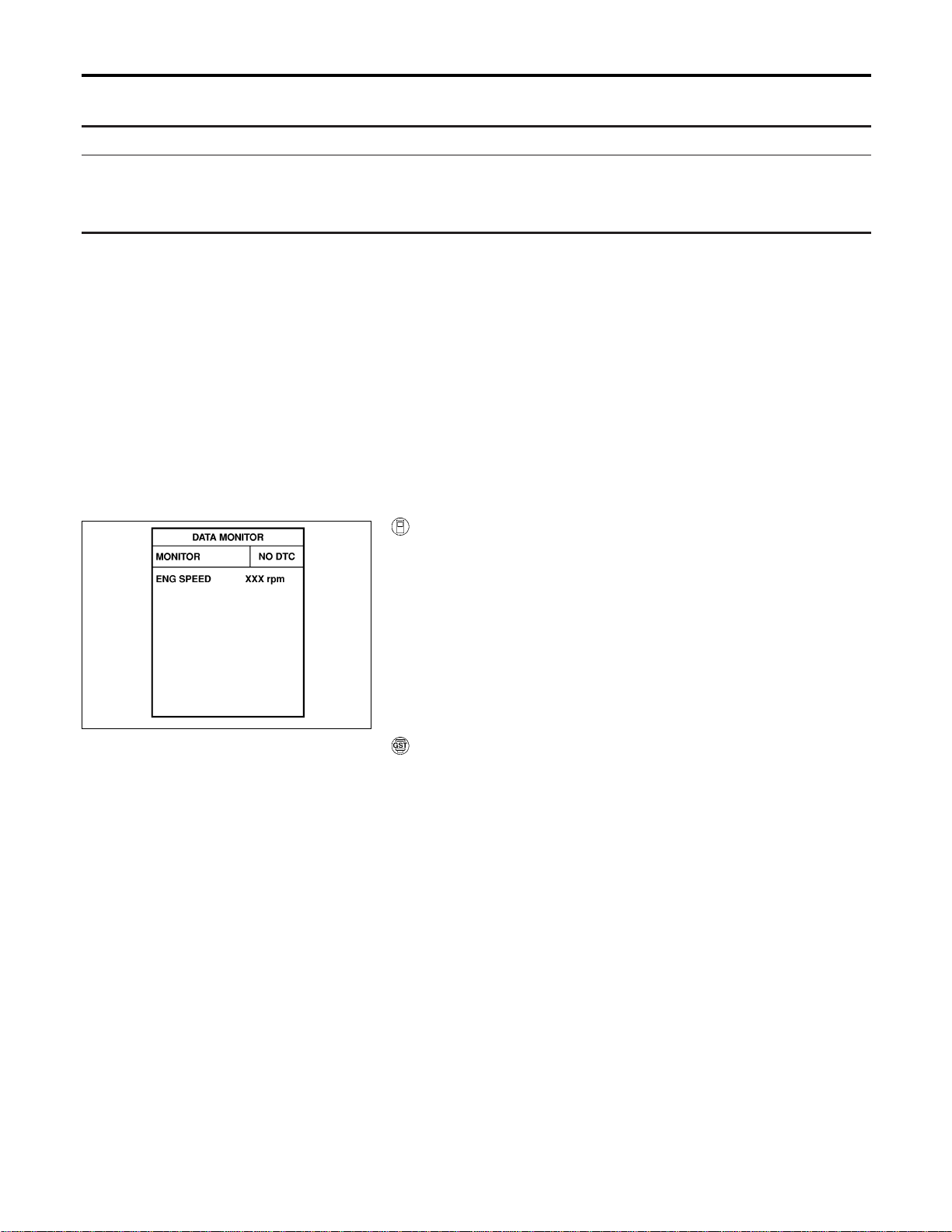
FAIL-SAFE MODE
=NFEC1440S01
When the malfunction is detected, ECM enters in fail-safe mode and the MIL lights up.
Engine operation condition in fail-safe mode
The ECM controls the electric throttle control actuator in regulating the throttle opening in order for the idle position to be within
+10 degrees.
The ECM regulates an opening speed of approx. 5 seconds to an opening of 10 degrees.
So, the acceleration will be poor.
DTC Confirmation Procedure
NFEC1441
NOTE:
If “DTC Confirmation Procedure” has been previously conducted,
always turn ignition switch “OFF” and wait at least 10 seconds
before conducting the next test.
TESTING CONDITION:
Before performing the following procedure, confirm that bat-
tery voltage is more than 10V at idle.
SEF058Y
With CONSULT-II
1. Turn ignition switch “ON”.
2. Select “DATA MONITOR” mode with CONSULT-II.
3. Start engine and let it idle for 1 second.
4. If DTC is detected, go to “Diagnostic Procedure”, EC-314.
With GST
Follow the procedure “WITH CONSULT-II” above.
DTC P0227, P0228 APP SENSOR
On Board Diagnosis Logic (Cont’d)
EC-312
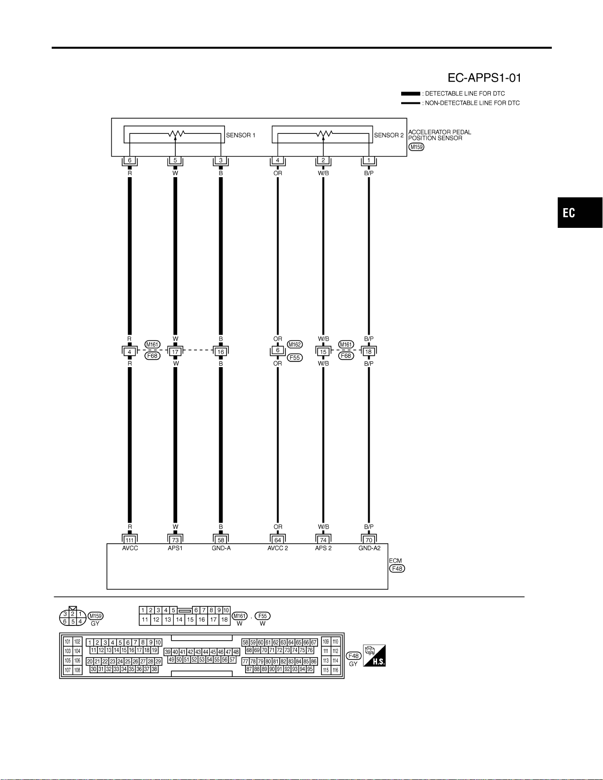
Wiring Diagram
NFEC1390
MEC926D
GI
MA
EM
LC
FE
CL
MT
AT
AX
SU
BR
ST
RS
BT
HA
SC
EL
IDX
DTC P0227, P0228 APP SENSOR
Wiring Diagram
EC-313
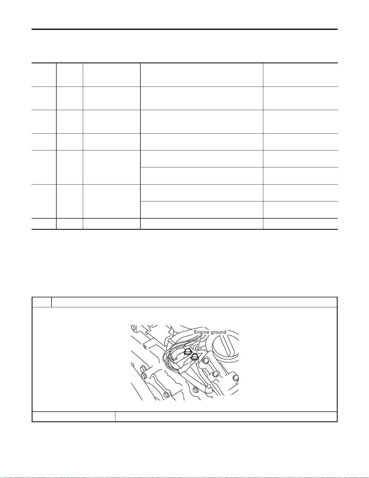
Specification data are reference values and are measured between each terminal and ground.
CAUTION:
Do not use ECM ground terminals when measuring input/output voltage. Doing so may result in dam-
age to the ECM’s transistor. Use a ground other than ECM terminals, such as the ground.
TERMI-
NAL
NO.
WIRE
COLOR
ITEM CONDITION DATA (DC Voltage)
58 B Sensors’ ground
[Engine is running]
I Warm-up condition
I Idle speed
Approximately 0V
64 OR
Accelerator pedal posi-
tion sensor 2 power
supply
[Ignition switch “ON”] Approximately 2.5V
70 B/P
Accelerator pedal posi-
tion sensor 2 ground
[Ignition switch “ON”] Approximately 0V
73 W
Accelerator pedal posi-
tion sensor 1
[Ignition switch “ON”]
I Accelerator pedal fully released
0.41 - 0.71V
[Ignition switch “ON”]
I Accelerator pedal fully depressed
More than 3.7V
74 W/B
Accelerator pedal posi-
tion sensor 2
[Ignition switch “ON”]
I Accelerator pedal fully released
0.08 - 0.48V
[Ignition switch “ON”]
I Accelerator pedal fully depressed
More than 1.8V
111 R Sensor’s power supply [Ignition switch “ON”] Approximately 5V
Diagnostic Procedure
NFEC1391
1 RETIGHTEN GROUND SCREWS
1. Turn ignition switch “OFF”.
2. Loosen and retighten engine ground screws.
SEC047D
© GO TO 2.
DTC P0227, P0228 APP SENSOR
Wiring Diagram (Cont’d)
EC-314
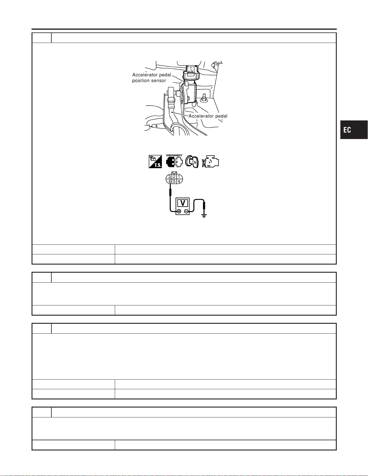
2 CHECK APP SENSOR 1 POWER SUPPLY CIRCUIT
1. Disconnect accelerator pedal position (APP) sensor harness connector.
2. Turn ignition switch “ON”.
SEC081D
3. Check voltage between APP sensor terminals 6 and ground with CONSULT-II or tester.
SEC093D
Voltage: Approximately 5V
OK or NG
OK © GO TO 4.
NG © GO TO 3.
3 DETECT MALFUNCTIONING PART
Check the following.
I Harness connectors M161, F68
I Harness for open or short between ECM and accelerator pedal position sensor
© Repair open circuit or short to ground or short to power in harness or connectors.
4 CHECK APP SENSOR 1 GROUND CIRCUIT FOR OPEN AND SHORT
1. Turn ignition switch “OFF”.
2. Check harness continuity between APP sensor terminal 3 and engine ground.
Refer to Wiring Diagram.
Continuity should exist.
3. Also check harness for short to ground and short to power.
OK or NG
OK © GO TO 6.
NG © GO TO 5.
5 DETECT MALFUNCTIONING PART
Check the following.
I Harness connectors M161, F68
I Harness for open or short between ECM and accelerator pedal position sensor
© Repair open circuit or short to ground or short to power in harness or connectors.
GI
MA
EM
LC
FE
CL
MT
AT
AX
SU
BR
ST
RS
BT
HA
SC
EL
IDX
DTC P0227, P0228 APP SENSOR
Diagnostic Procedure (Cont’d)
EC-315
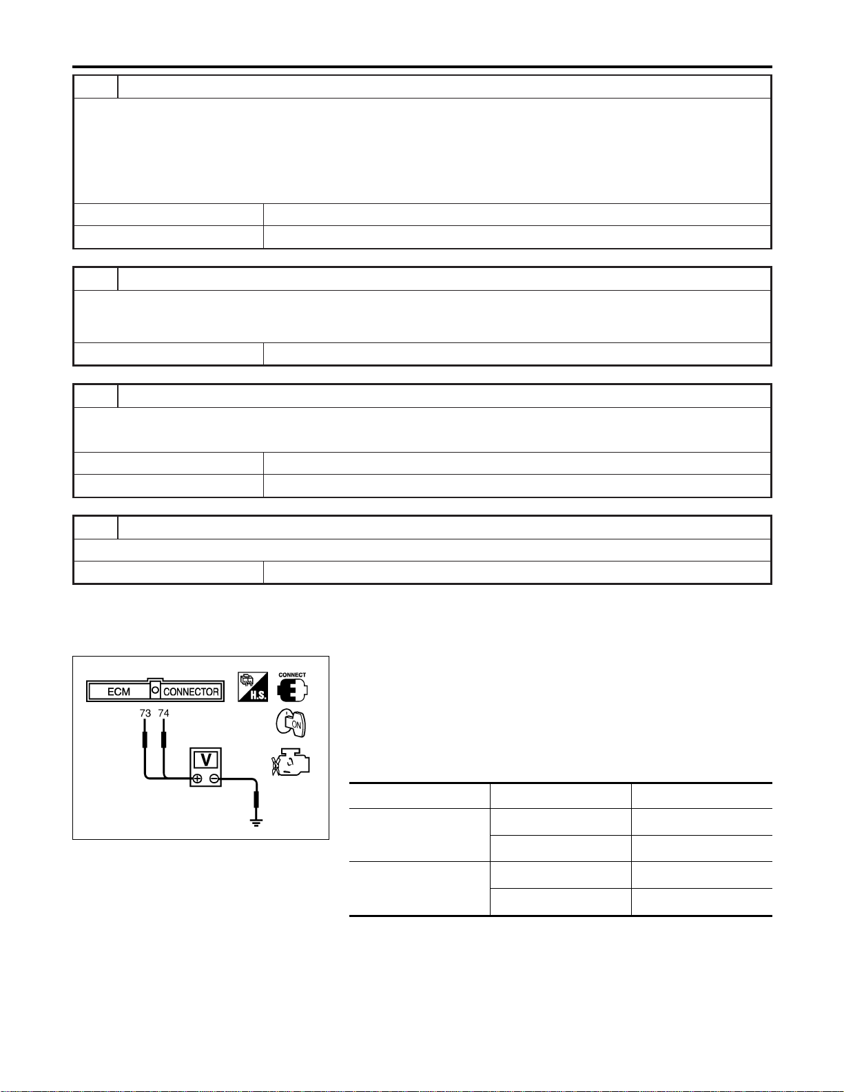
6 CHECK APP SENSOR 1 INPUT SIGNAL CIRCUIT FOR OPEN AND SHORT
1. Disconnect ECM harness connector.
2. Check harness continuity between ECM terminal 73 and APP sensor terminal 5.
Refer to Wiring Diagram
Continuity should exist.
3. Also check harness for short to ground and short to power.
OK or NG
OK © GO TO 8.
NG © GO TO 7.
7 DETECT MALFUNCTIONING PART
Check the following.
I Harness connectors M161, F68
I Harness for open or short between ECM and accelerator pedal position sensor
© Repair open circuit or short to ground or short to power in harness or connectors.
8 CHECK APP SENSOR
Refer to “Component Inspection”, EC-316.
OK or NG
OK © GO TO 9.
NG © Replace accelerator pedal assembly.
9 CHECK INTERMITTENT INCIDENT
Refer to “TROUBLE DIAGNOSIS FOR INTERMITTENT INCIDENT”, EC-156.
© IINSPECTION END
SEC901C
Component Inspection
NFEC1442
ACCELERATOR PEDAL POSITION SENSOR
1. Reconnect all harness connectors disconnected.
2. Turn ignition switch “ON”.
3. Check voltage between ECM terminals 73 (APP sensor 1
signal), 74 (APP sensor 2 signal) and engine ground under the
following conditions.
Terminal Accelerator pedal Voltage
73
(Accelerator pedal posi-
tion sensor 1)
Fully released 0.41 - 0.71V
Fully depressed More than 3.7V
74
(Accelerator pedal posi-
tion sensor 2)
Fully released 0.08 - 0.48V
Fully depressed More than 1.8V
4. If NG, replace accelerator pedal assembly.
5. Perform “Accelerator Pedal Released Position Learning”,
EC-71.
6. Perform “Throttle Valve Closed Position Learning”, EC-71.
7. Perform “Idle Air Volume Learning”, EC-71.
DTC P0227, P0228 APP SENSOR
Diagnostic Procedure (Cont’d)
EC-316
On Board Diagnosis Logic
NFEC0929
When a misfire occurs, engine speed will fluctuate. If the engine
speed fluctuates enough to cause the CKP sensor signal to vary,
ECM can determine that a misfire is occurring.
Sensor Input Signal to ECM ECM function
Crankshaft position sensor (POS) Engine speed On board diagnosis of misfire
The misfire detection logic consists of the following two conditions.
1. One Trip Detection Logic (Three Way Catalyst Damage)
On the first trip that a misfire condition occurs that can dam-
age the three way catalyst (TWC) due to overheating, the MIL
will blink.
When a misfire condition occurs, the ECM monitors the CKP
sensor signal every 200 engine revolutions for a change.
When the misfire condition decreases to a level that will not
damage the TWC, the MIL will turn off.
If another misfire condition occurs that can damage the TWC
on a second trip, the MIL will blink.
When the misfire condition decreases to a level that will not
damage the TWC, the MIL will remain on.
If another misfire condition occurs that can damage the TWC,
the MIL will begin to blink again.
2. Two Trip Detection Logic (Exhaust quality deterioration)
For misfire conditions that will not damage the TWC (but will
affect vehicle emissions), the MIL will only light when the mis-
fire is detected on a second trip. During this condition, the ECM
monitors the CKP sensor signal every 1,000 engine revolu-
tions.
A misfire malfunction can be detected on any one cylinder or
on multiple cylinders.
DTC No.
Trouble diagnosis
name
DTC Detecting Condition Possible Cause
P0300
0300
Multiple cylinder mis-
fire detected
Multiple cylinders misfire, No. 1 cylinder misfires,
No. 2 cylinder misfires, No. 3 cylinder misfires, No.
4 cylinder misfires, No. 5 cylinder misfires and No.
6 cylinder misfires.
I Improper spark plug
I Insufficient compression
I Incorrect fuel pressure
I The injector circuit is open or shorted
I Injectors
I Intake air leak
I The ignition secondary circuit is open
or shorted
I Lack of fuel
I Drive plate or flywheel
I Heated oxygen sensor 1
I Incorrect PCV hose connection
P0301
0301
No. 1 cylinder misfire
detected
P0302
0302
No. 2 cylinder misfire
detected
P0303
0303
No. 3 cylinder misfire
detected
P0304
0304
No. 4 cylinder misfire
detected
P0305
0305
No. 5 cylinder misfire
detected
P0306
0306
No. 6 cylinder misfire
detected
GI
MA
EM
LC
FE
CL
MT
AT
AX
SU
BR
ST
RS
BT
HA
SC
EL
IDX
DTC P0300 - P0306 MULTIPLE CYLINDER MISFIRE, NO.1-6CYLINDER
MISFIRE
On Board Diagnosis Logic
EC-317
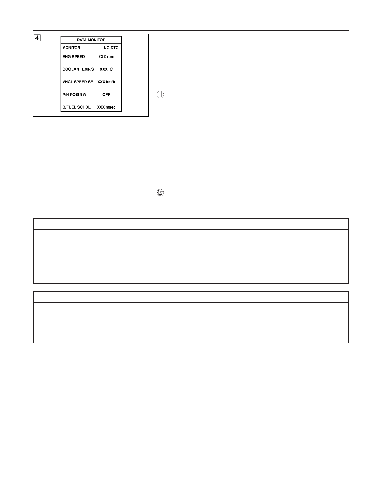
SEF213Y
DTC Confirmation Procedure
NFEC0930
CAUTION:
Always drive vehicle at a safe speed.
NOTE:
If “DTC Confirmation Procedure” has been previously conducted,
always turn ignition switch “OFF” and wait at least 10 seconds
before conducting the next test.
WITH CONSULT-II
NFEC0930S01
1) Turn ignition switch “ON”, and select “DATA MONITOR” mode
with CONSULT-II.
2) Start engine and warm it up to normal operating temperature.
3) Turn ignition switch “OFF” and wait at least 10 seconds.
4) Start engine again and drive at 1,500 to 3,000 rpm for at least
3 minutes.
Hold the accelerator pedal as steady as possible.
NOTE:
Refer to the freeze frame data for the test driving conditions.
5) If 1st trip DTC is detected, go to “Diagnostic Procedure”,
EC-318.
WITH GST
NFEC0930S02
Follow the procedure “With CONSULT-II” above.
Diagnostic Procedure
NFEC0931
1 CHECK FOR INTAKE AIR LEAK
1. Start engine and run it at idle speed.
2. Listen for the sound of the intake air leak.
3. Check PCV hose connection.
OK or NG
OK © GO TO 2.
NG © Discover air leak location and repair.
2 CHECK FOR EXHAUST SYSTEM CLOGGING
1. Stop engine and visually check exhaust tube, three way catalyst and muffler for dents.
OK or NG
OK © GO TO 3.
NG © Repair or replace it.
DTC P0300 - P0306 MULTIPLE CYLINDER MISFIRE, NO.1-6CYLINDER
MISFIRE
DTC Confirmation Procedure
EC-318
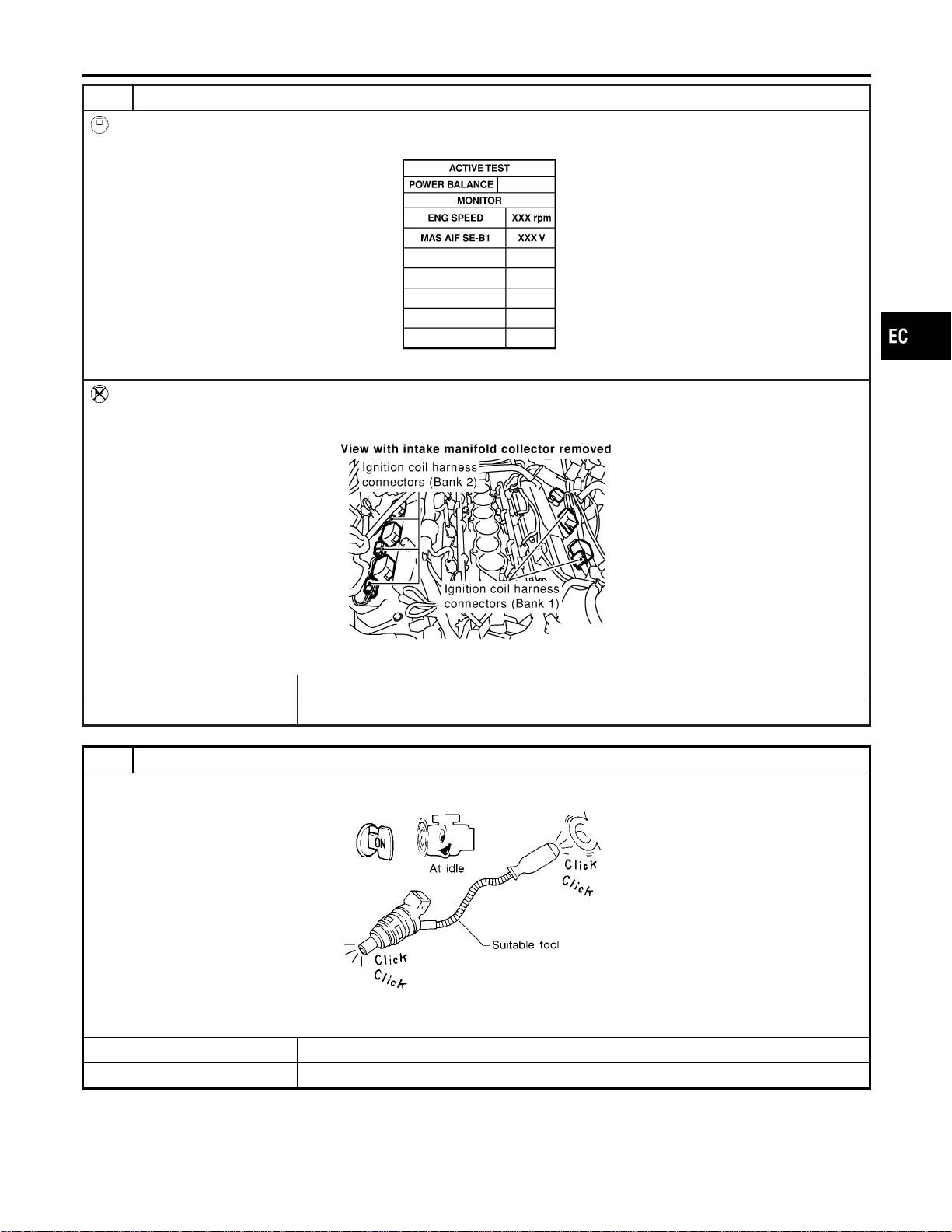
3 PERFORM POWER BALANCE TEST
With CONSULT-II
1. Perform “POWER BALANCE” in “ACTIVE TEST” mode.
SEC136D
2. Is there any cylinder which does not produce a momentary engine speed drop?
Without CONSULT-II
When disconnecting each ignition coil harness connector one at a time, is there any cylinder which does not produce a
momentary engine speed drop?
SEC120D
YesorNo
Yes © GO TO 5.
No © GO TO 4.
4 CHECK INJECTOR
Does each injector make an operating sound at idle?
MEC703B
YesorNo
Yes © GO TO 5.
No © Check injector(s) and circuit(s). Refer to EC-703.
GI
MA
EM
LC
FE
CL
MT
AT
AX
SU
BR
ST
RS
BT
HA
SC
EL
IDX
DTC P0300 - P0306 MULTIPLE CYLINDER MISFIRE, NO.1-6CYLINDER
MISFIRE
Diagnostic Procedure (Cont’d)
EC-319
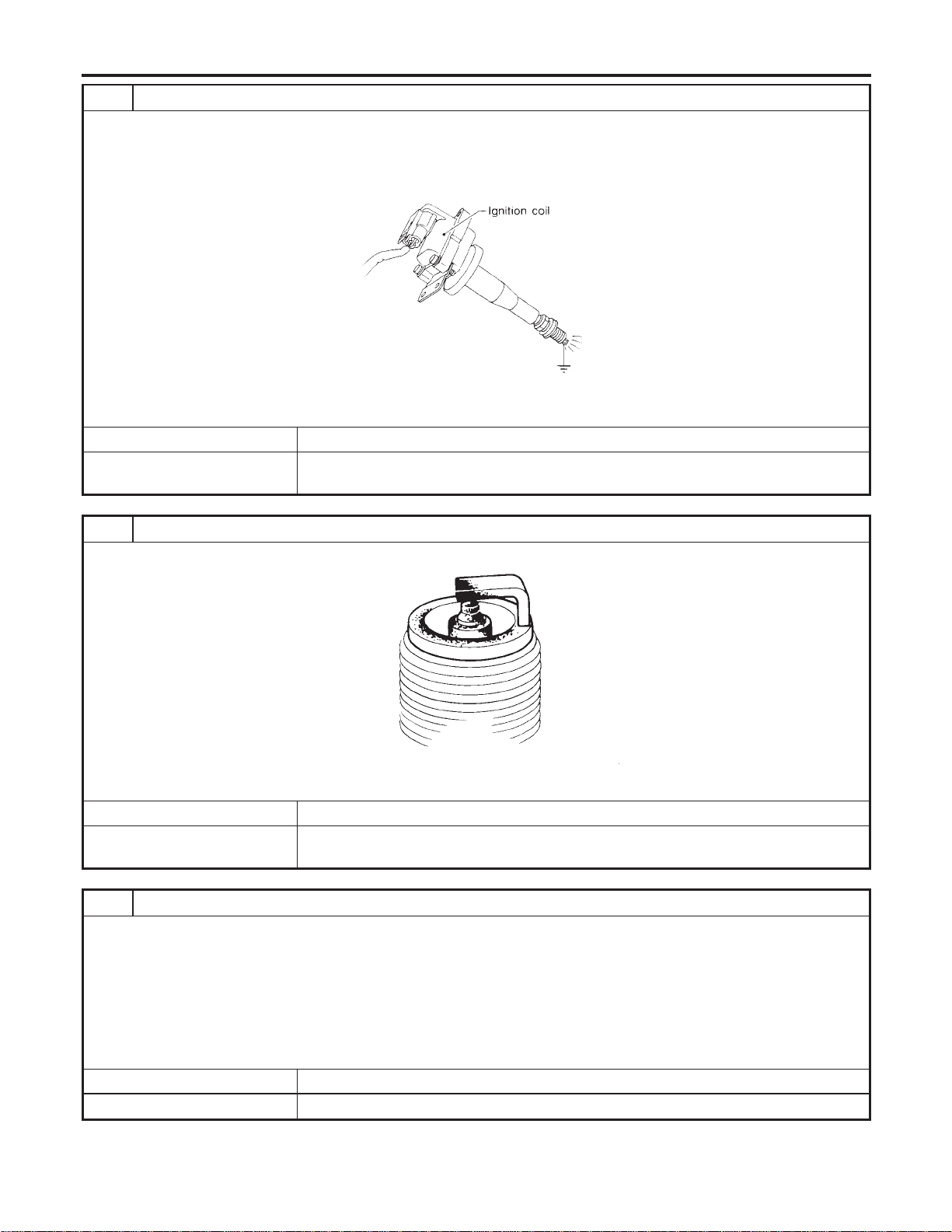
5 CHECK IGNITION SPARK
1. Disconnect ignition wire from spark plug.
2. Connect a known good spark plug to the ignition wire.
3. Place end of spark plug against a suitable ground and crank engine.
4. Check for spark.
SEF575Q
OK or NG
OK © GO TO 6.
NG © Check ignition coil, power transistor and their circuits. Refer to “IGNITION SIGNAL”,
EC-692.
6 CHECK SPARK PLUGS
Remove the spark plugs and check for fouling, etc.
SEF156I
OK or NG
OK © GO TO 7.
NG © Repair or replace spark plug(s) with standard type one(s). For spark plug type, refer to
MA-17, “Changing Spark Plugs”.
7 CHECK COMPRESSION PRESSURE
Check compression pressure. Refer to EM-13, “Measurement of Compression Pressure”.
Standard:
1,275 kPa (13.0 kg/cm
2
, 185 psi)/300 rpm
Minimum:
981 kPa (10.0 kg/cm
2
, 142 psi)/300 rpm
Difference between each cylinder:
98 kPa (1.0 kg/cm
2
, 14 psi)/300 rpm
OK or NG
OK © GO TO 8.
NG © Check pistons, piston rings, valves, valve seats and cylinder head gaskets.
DTC P0300 - P0306 MULTIPLE CYLINDER MISFIRE, NO.1-6CYLINDER
MISFIRE
Diagnostic Procedure (Cont’d)
EC-320
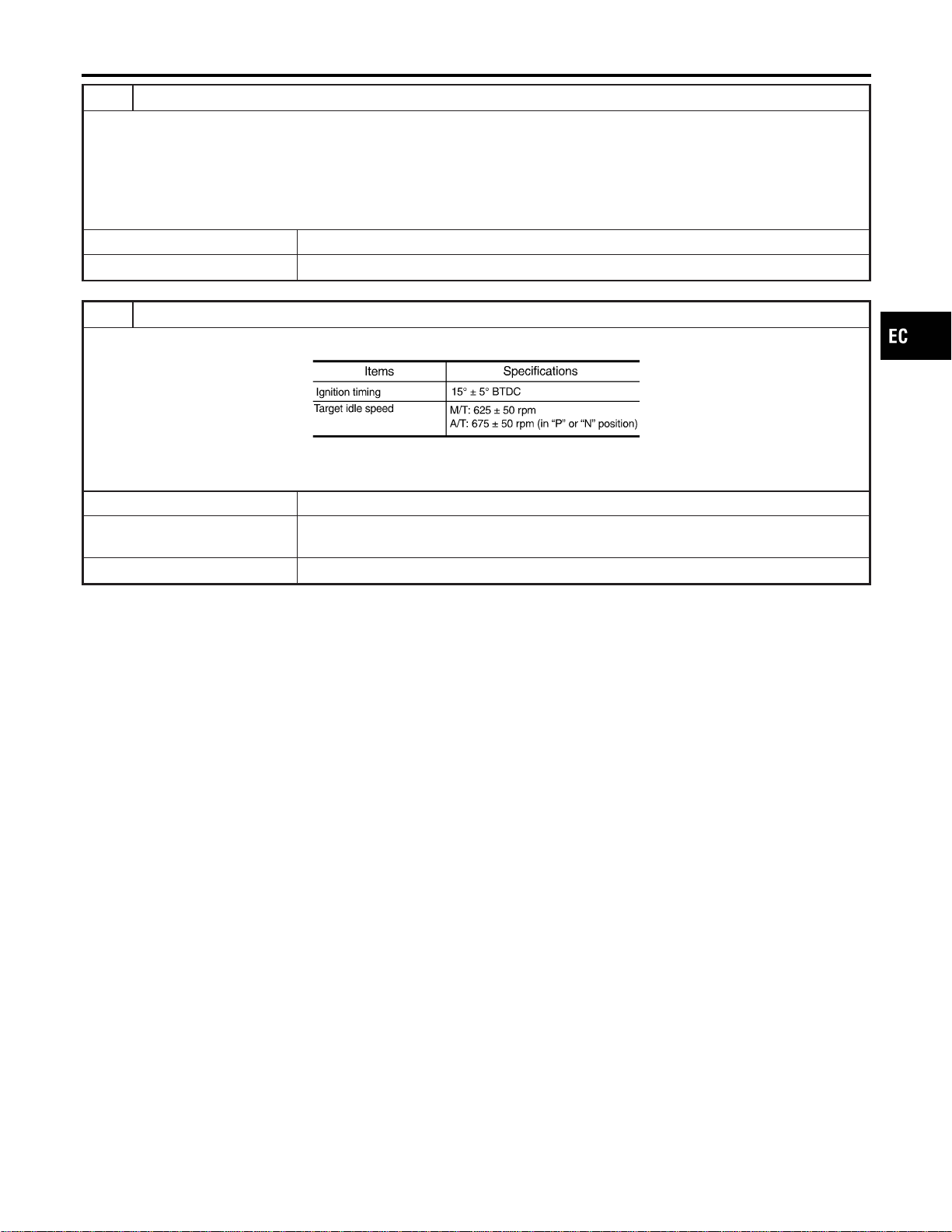
8 CHECK FUEL PRESSURE
1. Install all removed parts.
2. Release fuel pressure to zero. Refer to EC-56.
3. Install fuel pressure gauge and check fuel pressure. Refer to EC-56.
At idle:
Approx. 350 kPa (3.7 kg/cm
2
, 51 psi)
OK or NG
OK © GO TO 9.
NG © Follow the construction of “Fuel Pressure Check”, EC-56.
9 CHECK IGNITION TIMING
Check the following items. Refer to “Basic Inspection”, EC-123.
MTBL1186
OK or NG
OK (With CONSULT-II) © GO TO 10.
OK (Without CONSULT-
II)
© GO TO 11.
NG © Follow the “Basic Inspection”.
GI
MA
EM
LC
FE
CL
MT
AT
AX
SU
BR
ST
RS
BT
HA
SC
EL
IDX
DTC P0300 - P0306 MULTIPLE CYLINDER MISFIRE, NO.1-6CYLINDER
MISFIRE
Diagnostic Procedure (Cont’d)
EC-321
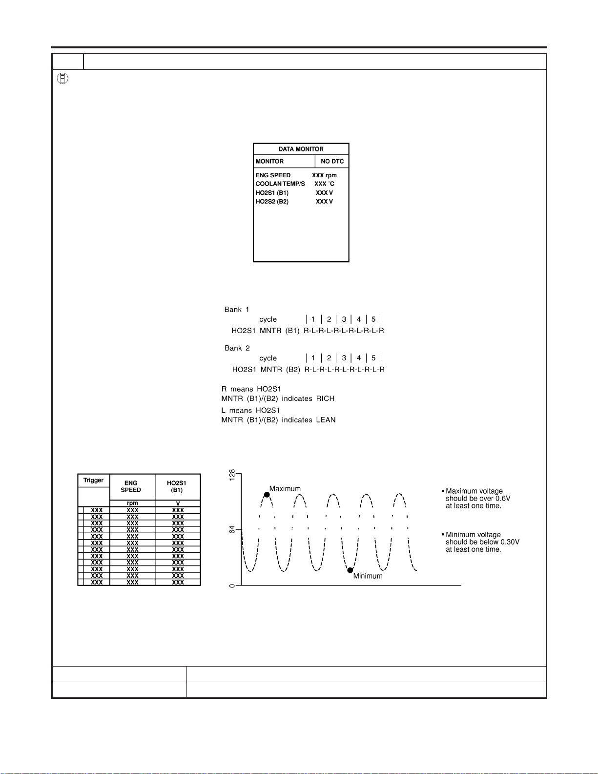
10 CHECK HEATED OXYGEN SENSOR 1
With CONSULT-II
1. Start engine and warm it up to normal operating temperature.
2. Select “MANU TRIG” and “HI SPEED” in “DATA MONITOR” mode with CONSULT-II, and select “HO2S1 (B1)/(B2)” and
“HO2S1 MNTR (B1)/(B2)”.
3. Hold engine speed at 2,000 rpm under no load during the following steps.
4. Touch “RECORD” on CONSULT-II screen.
SEF967Y
5. Check the following.
I “HO2S1 MNTR (B1)/(B2)” in “DATA MONITOR” mode changes from “RICH” to “LEAN” to “RICH” 5 times in 10 seconds.
5 times (cycles) are counted as shown left:
SEF647Y
I “HO2S1 (B1)/(B2)” voltage goes above 0.6V at least once.
I “HO2S1 (B1)/(B2)” voltage goes below 0.3V at least once.
I “HO2S1 (B1)/(B2)” voltage never exceeds 1.0V.
SEF648Y
CAUTION:
I Discard any heated oxygen sensor which has been dropped from a height of more than 0.5 m (19.7 in) onto a
hard surface such as a concrete floor; use a new one.
I Before installing new oxygen sensor, clean exhaust system threads using Oxygen Sensor Thread Cleaner tool
J-43897-18 or J-43897-12 and approved anti-seize lubricant.
OK or NG
OK © GO TO 12.
NG © Replace malfunctioning heated oxygen sensor 1.
DTC P0300 - P0306 MULTIPLE CYLINDER MISFIRE, NO.1-6CYLINDER
MISFIRE
Diagnostic Procedure (Cont’d)
EC-322
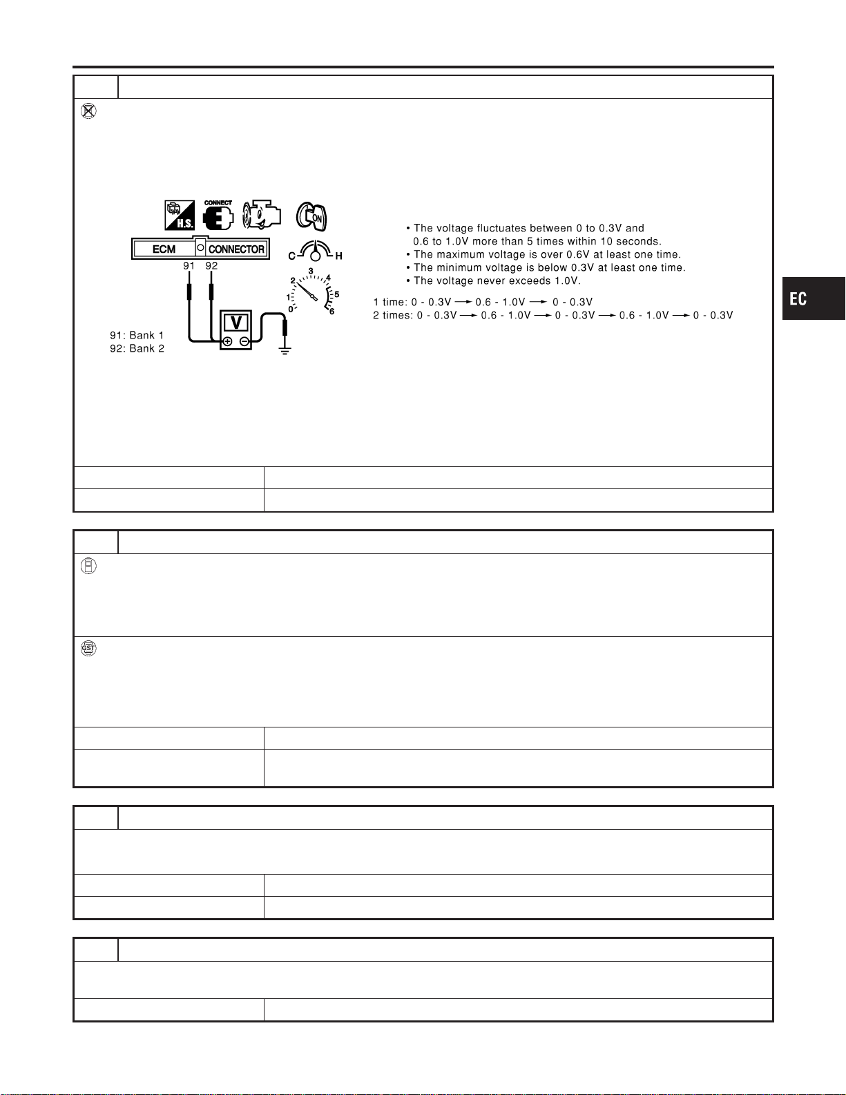
11 CHECK HEATED OXYGEN SENSOR 1
Without CONSULT-II
1. Start engine and warm it up to normal operating temperature.
2. Set voltmeter probes between ECM terminal 91 (HO2S1 bank 1 signal) or 92 (HO2S1 bank 2 signal) and engine
ground.
3. Check the following with engine speed held at 2,000 rpm constant under no load.
SEC109D
CAUTION:
I Discard any heated oxygen sensor which has been dropped from a height of more than 0.5 m (19.7 in) onto a
hard surface such as a concrete floor; use a new one.
I Before installing new oxygen sensor, clean exhaust system threads using Oxygen Sensor Thread Cleaner tool
J-43897-18 or J-43897-12 and approved anti-seize lubricant.
OK or NG
OK © GO TO 12.
NG © Replace malfunctioning heated oxygen sensor 1.
12 CHECK MASS AIR FLOW SENSOR
With CONSULT-II
Check mass air flow sensor signal in “DATA MONITOR” mode with CONSULT-II.
2.0 - 6.0 g·m/sec: at idling
7.0 - 20.0 g·m/sec: at 2,500 rpm
With GST
Check mass air flow sensor signal in MODE 1 with GST.
2.0 - 6.0 g·m/sec: at idling
7.0 - 20.0 g·m/sec: at 2,500 rpm
OK or NG
OK © GO TO 13.
NG © Check connectors for rusted terminals or loose connections in the mass air flow sensor
circuit or engine grounds. Refer to EC-195.
13 CHECK SYMPTOM MATRIX CHART
Check items on the rough idle symptom in “Symptom Matrix Chart”, EC-131.
OK or NG
OK © GO TO 14.
NG © Repair or replace.
14 ERASE THE 1ST TRIP DTC
Erase the 1st trip DTC from the ECM memory after performing the tests. Refer to EC-91.
Some tests may cause a 1st trip DTC to be set.
© GO TO 15.
GI
MA
EM
LC
FE
CL
MT
AT
AX
SU
BR
ST
RS
BT
HA
SC
EL
IDX
DTC P0300 - P0306 MULTIPLE CYLINDER MISFIRE, NO.1-6CYLINDER
MISFIRE
Diagnostic Procedure (Cont’d)
EC-323

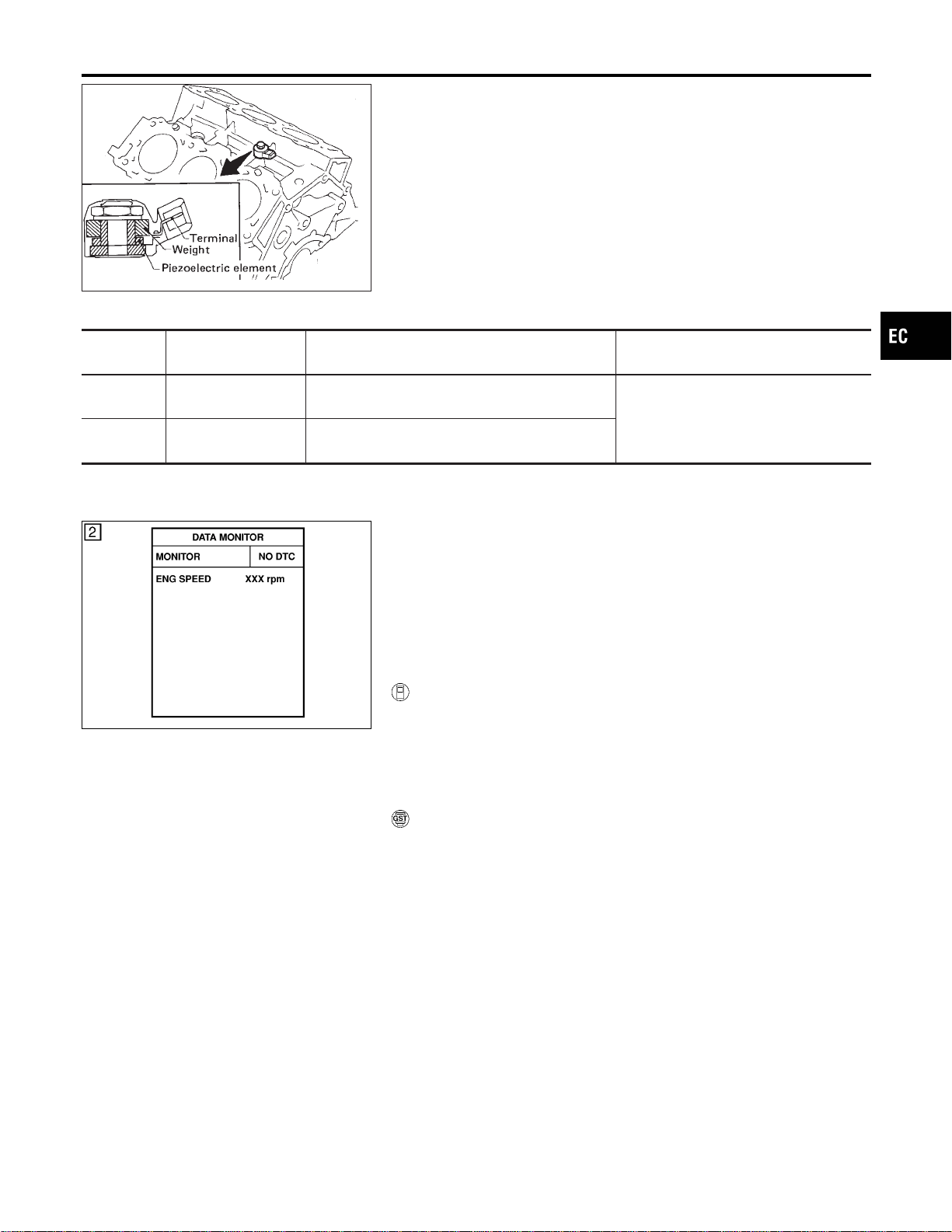
SEF332I
Component Description
NFEC0932
The knock sensor is attached to the cylinder block. It senses
engine knocking using apiezoelectric element.Aknocking vibration
from the cylinder block is sensed as vibrational pressure. This
pressure is converted into a voltage signal and sent to the ECM.
Freeze frame data will not be stored in the ECM for the knock
sensor. The MIL will not light for knock sensor malfunction.
On Board Diagnosis Logic
NFEC0934
DTC No.
Trouble diagnosis
name
DTC Detecting Condition Possible Cause
P0327
0327
Knock sensor circuit
low input
An excessively low voltage from the sensor is sent
to ECM.
I Harness or connectors
(The sensor circuit is open or
shorted.)
I Knock sensor
P0328
0328
Knock sensor circuit
high input
An excessively high voltage from the sensor is
sent to ECM.
SEF058Y
DTC Confirmation Procedure
NFEC0935
NOTE:
If “DTC Confirmation Procedure” has been previously conducted,
always turn ignition switch “OFF” and wait at least 10 seconds
before conducting the next test.
TESTING CONDITION:
Before performing the following procedure, confirm that bat-
tery voltage is more than 10V at idle.
WITH CONSULT-II
NFEC0935S01
1) Turn ignition switch “ON” and select “DATA MONITOR” mode
with CONSULT-II
2) Start engine and run it for at least 5 seconds at idle speed.
3) If 1st trip DTC is detected, go to “Diagnostic Procedure”,
EC-327.
WITH GST
NFEC0935S03
Follow the procedure “With CONSULT-II” above.
GI
MA
EM
LC
FE
CL
MT
AT
AX
SU
BR
ST
RS
BT
HA
SC
EL
IDX
DTC P0327, P0328 KS
Component Description
EC-325
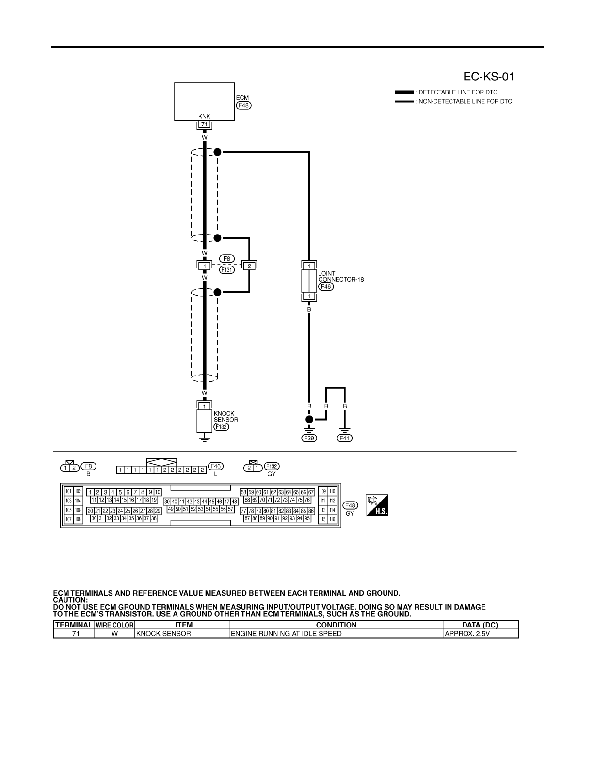
Wiring Diagram
NFEC0936
MEC492D
SEC117D
DTC P0327, P0328 KS
Wiring Diagram
EC-326
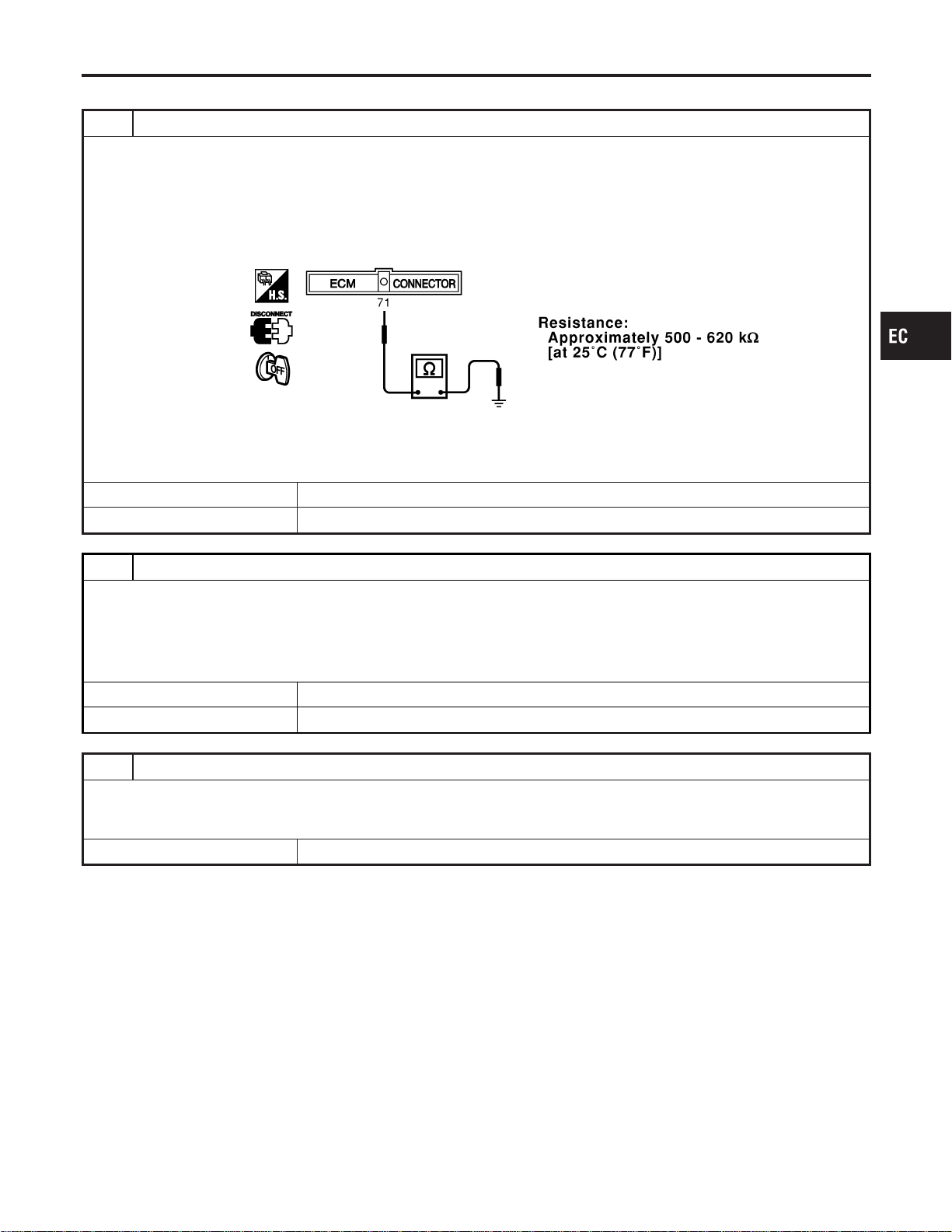
Diagnostic Procedure
NFEC0937
1 CHECK KNOCK SENSOR INPUT SIGNAL CIRCUIT FOR OPEN AND SHORT-I
1. Turn ignition switch “OFF”.
2. Disconnect ECM harness connector.
3. Check resistance between ECM terminal 71 and engine ground.
NOTE:
It is necessary to use an ohmmeter which can measure more than 10 MΩ.
SEC118D
4. Also check harness for short to ground and short to power.
OK or NG
OK © GO TO 5.
NG © GO TO 2.
2 CHECK KNOCK SENSOR INPUT SIGNAL CIRCUIT FOR OPEN AND SHORT-II
1. Disconnect knock sensor harness connector.
2. Check harness continuity between ECM terminal 71 and knock sensor terminal 1. Refer to Wiring Diagram.
Continuity should exist.
3. Also check harness for short to ground and short to power.
OK or NG
OK © GO TO 4.
NG © GO TO 3.
3 DETECT MALFUNCTIONING PART
Check the following.
I Harness connectors F8, F131
I Harness for open or short between ECM and knock sensor
© Repair open circuit or short to ground or short to power in harness or connectors.
GI
MA
EM
LC
FE
CL
MT
AT
AX
SU
BR
ST
RS
BT
HA
SC
EL
IDX
DTC P0327, P0328 KS
Diagnostic Procedure
EC-327
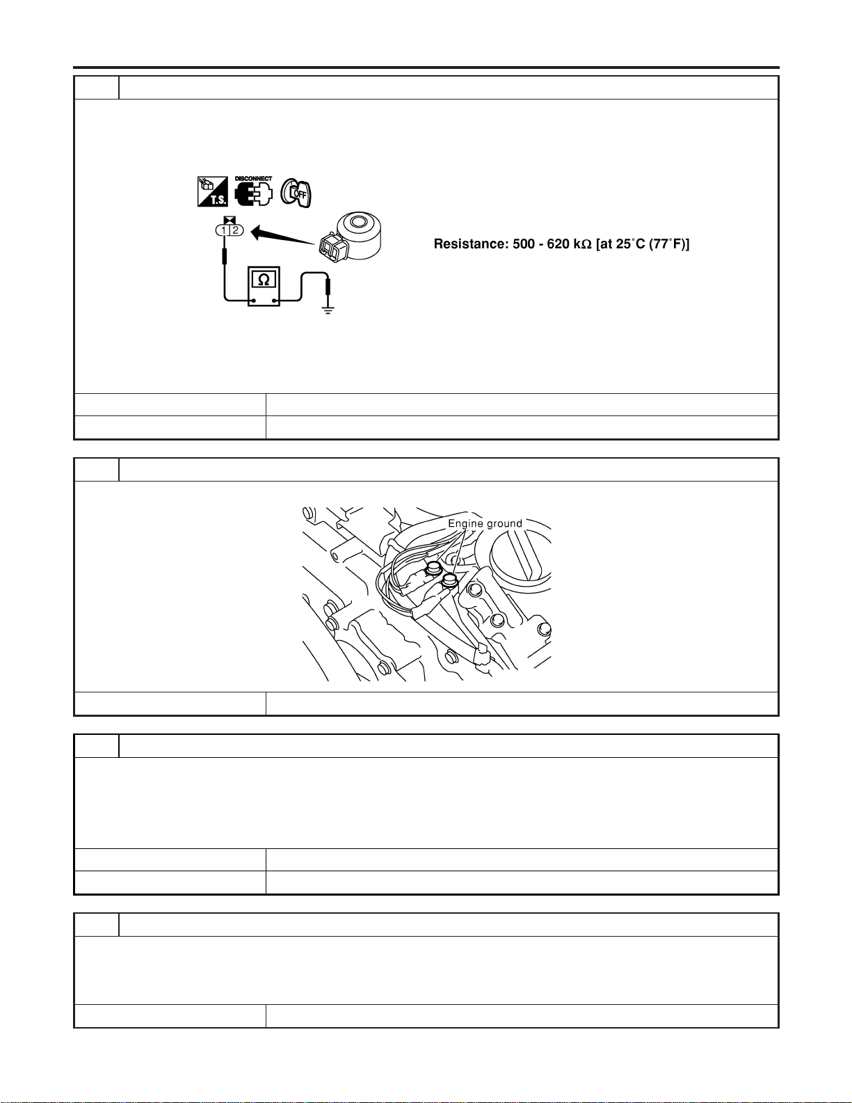
4 CHECK KNOCK SENSOR
Check resistance between knock sensor terminal 1 and ground.
NOTE:
It is necessary to use an ohmmeter which can measure more than 10 MΩ.
SEC119D
CAUTION:
Do not use any knock sensors that have been dropped or physically damaged. Use only new ones.
OK or NG
OK © GO TO 8.
NG © Replace knock sensor.
5 RETIGHTEN GROUND SCREWS
Loose and retighten engine ground screws.
SEC047D
© GO TO 6.
6 CHECK KNOCK SENSOR SHIELD CIRCUIT FOR OPEN AND SHORT
1. Disconnect harness connectors F8, F131.
2. Check harness continuity between harness connector F8 terminal 2 and engine ground.
Continuity should exist.
3. Also check harness for short to power.
OK or NG
OK © GO TO 8.
NG © GO TO 7.
7 DETECT MALFUNCTIONING PART
Check the following.
I Harness connectors F8, F131
I Joint connector-18
I Harness for open or short between harness connector F8 and engine ground
© Repair open circuit or short to power in harness or connectors.
DTC P0327, P0328 KS
Diagnostic Procedure (Cont’d)
EC-328
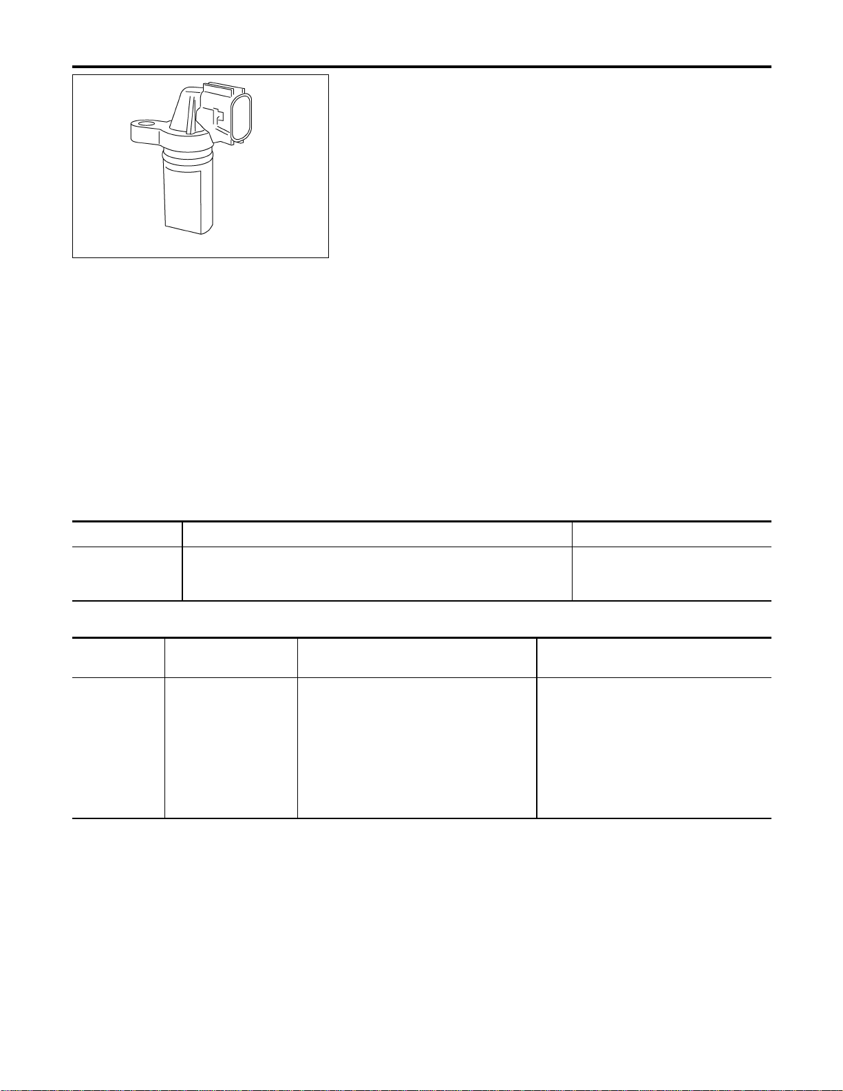
PBIB0562E
Component Description
NFEC0938
The crankshaft position sensor (POS) is located on the oil pan
facing the gear teeth (cogs) of the signal plate at the end of the
crankshaft. It detects the fluctuation of the engine revolution.
The sensor consists of a permanent magnet and Hall IC.
When the engine is running, the high and low parts of the teeth
cause the gap with the sensor change.
The changing gap causes the magnetic field near the sensor to
change.
Due to the changing magnetic field, the voltage from the sensor
changes.
The ECM receives the voltage signal and detects the fluctuation of
the engine revolution.
CONSULT-II Reference Value in Data Monitor
Mode
NFEC0939
Specification data are reference values.
MONITOR ITEM CONDITION SPECIFICATION
ENG SPEED
I Tachometer: Connect
I Run engine and compare tachometer indication with the CONSULT-II
value.
Almost the same speed as the
CONSULT-II value.
On Board Diagnosis Logic
NFEC0941
DTC No.
Trouble diagnosis
name
DTC Detecting Condition Possible Cause
P0335
0335
Crankshaft position
sensor (POS) circuit
I The crankshaft position sensor signal is
not detected by the ECM during the first
few seconds of engine cranking.
I The proper pulse signal from the crank-
shaft position sensor (POS) is not sent to
ECM while the engine is running.
I The crankshaft position sensor signal is
not in the normal pattern during engine
running.
I Harness or connectors
[The crankshaft position sensor (POS)
circuit is open or shorted.]
I Crankshaft position sensor (POS)
I Signal plate
DTC P0335 CKP SENSOR (POS)
Component Description
EC-330

SEF058Y
DTC Confirmation Procedure
=NFEC0942
NOTE:
If “DTC Confirmation Procedure” has been previously conducted,
always turn ignition switch “OFF” and wait at least 10 seconds
before conducting the next test.
TESTING CONDITION:
Before performing the following procedure, confirm that bat-
tery voltage is more than 10.5V with ignition switch “ON”.
With CONSULT-II
1) Turn ignition switch “ON” and select “DATA MONITOR” mode
with CONSULT-II.
2) Crank engine for at least 2 seconds and run it for at least 5
seconds at idle speed.
3) If 1st trip DTC is detected, go to “Diagnostic Procedure”,
EC-333.
If 1st trip DTC is not detected, go to next step.
4) Maintaining engine speed at more than 1,000 rpm for at least
5 seconds.
5) If 1st trip DTC is detected, go to “Diagnostic Procedure”,
EC-333
With GST
Follow the procedure “With CONSULT-II” above.
GI
MA
EM
LC
FE
CL
MT
AT
AX
SU
BR
ST
RS
BT
HA
SC
EL
IDX
DTC P0335 CKP SENSOR (POS)
DTC Confirmation Procedure
EC-331
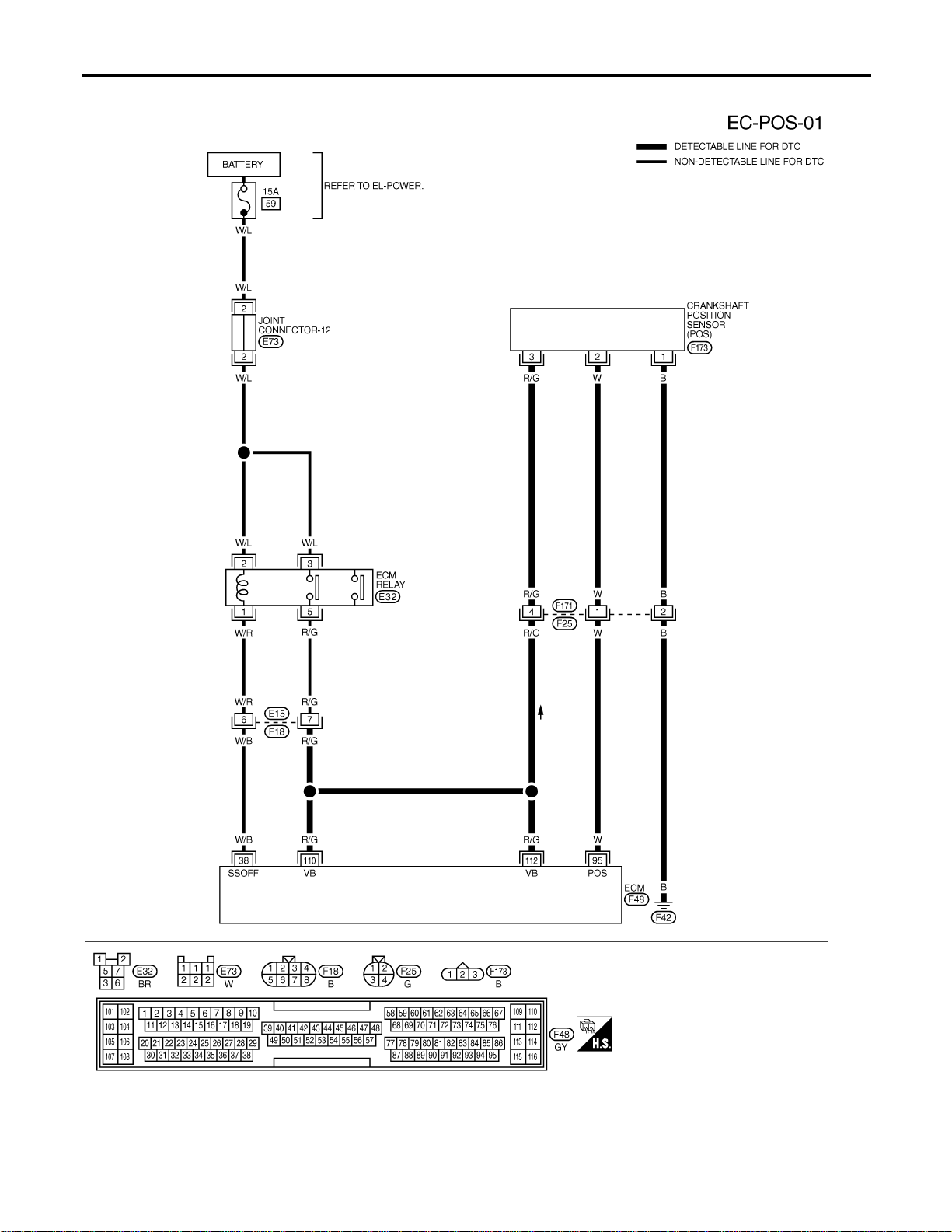
Wiring Diagram
NFEC0943
MEC493D
DTC P0335 CKP SENSOR (POS)
Wiring Diagram
EC-332
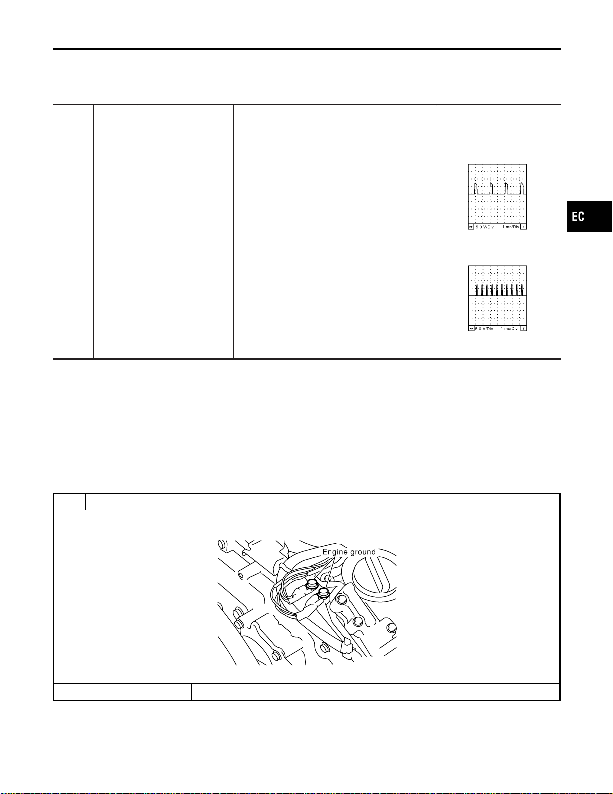
Specification data are reference values and are measured between each terminal and ground.
CAUTION:
Do not use ECM ground terminals when measuring input/output voltage. Doing so may result in dam-
age to the ECM’s transistor. Use a ground other than ECM terminals, such as the ground.
TERMI-
NAL
NO.
WIRE
COLOR
ITEM CONDITION DATA (DC Voltage)
95 W
Crankshaft position
sensor (POS)
[Engine is running]
I Idle speed
Approximately 2.4V★
SEC035D
[Engine is running]
I Engine speed is 2,000 rpm.
Approximately 2.3V★
SEC036D
★: Average voltage for pulse signal (Actual pulse signal can be confirmed by oscilloscope.)
Diagnostic Procedure
NFEC0944
1 RETIGHTEN GROUND SCREWS
1. Turn ignition switch “OFF”.
2. Loosen and retighten engine ground screws.
SEC047D
© GO TO 2.
GI
MA
EM
LC
FE
CL
MT
AT
AX
SU
BR
ST
RS
BT
HA
SC
EL
IDX
DTC P0335 CKP SENSOR (POS)
Wiring Diagram (Cont’d)
EC-333
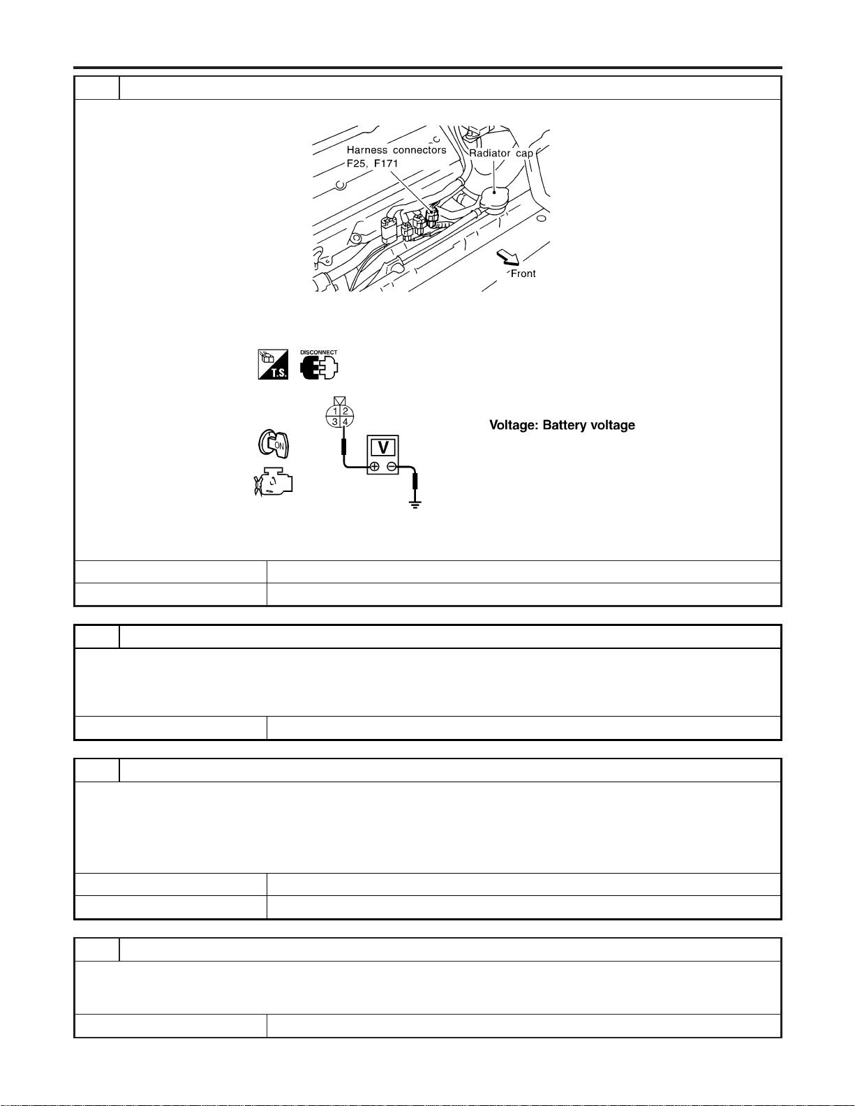
2 CHECK CKP SENSOR (POS) POWER SUPPLY CIRCUIT
1. Disconnect harness connectors F25, F171.
SEF511WB
2. Turn ignition switch “ON”.
3. Check voltage between harness connector F25 terminal 4 and ground with CONSULT-II or tester.
SEF323X
4. Also check harness for short to ground and short to power.
OK or NG
OK © GO TO 4.
NG © GO TO 3.
3 DETECT MALFUNCTIONING PART
Check the following.
I Harness connectors F25, F171 and E15, F18
I Harness for open or short between ECM and harness connector F25
I Harness for open or short between ECM relay and harness connector F25
© Repair open circuit or short to ground or short to power in harness or connectors.
4 CHECK CKP SENSOR (POS) GROUND CIRCUIT FOR OPEN AND SHORT
1. Turn ignition switch “OFF”.
2. Check harness continuity between harness connector F25 terminal 2 and engine ground. Refer to Wiring Diagram.
Continuity should exist.
3. Also check harness for short to power.
OK or NG
OK © GO TO 6.
NG © GO TO 5.
5 DETECT MALFUNCTIONING PART
Check the following.
I Harness connectors F25, F171
I Harness for open between harness connector F25 and ground
© Repair open circuit or short to power in harness or connectors.
DTC P0335 CKP SENSOR (POS)
Diagnostic Procedure (Cont’d)
EC-334
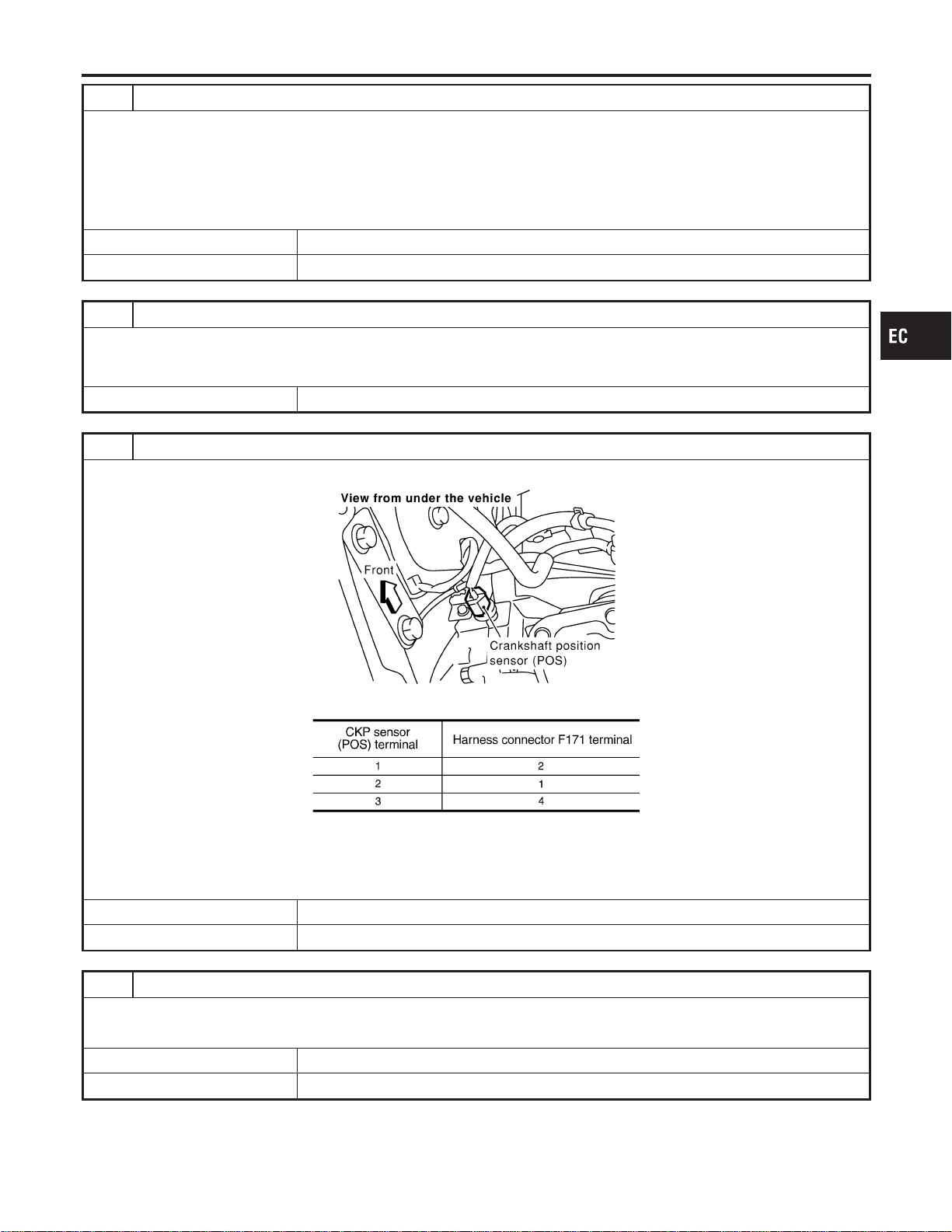
6 CHECK CKP SENSOR (POS) INPUT SIGNAL CIRCUIT FOR OPEN AND SHORT
1. Disconnect ECM harness connector.
2. Check harness continuity between ECM terminal 95 and harness connector F25 terminal 1.
Refer to Wiring Diagram.
Continuity should exist.
3. Also check harness for short to ground and short to power.
OK or NG
OK © GO TO 8.
NG © GO TO 7.
7 DETECT MALFUNCTIONING PART
Check the following.
I Harness connectors F25, F171
I Harness for open or short between ECM and harness connector F25
© Repair open circuit or short to ground or short to power in harness or connectors.
8 CHECK CKP SENSOR (POS) SUB-HARNESS CIRCUIT FOR OPEN AND SHORT
1. Disconnect CKP sensor (POS) harness connector.
SEC137D
2. Check harness continuity between CKP sensor (POS) terminals and harness connector F171 terminals as follows.
MTBL1191
Continuity should exist.
3. Also check harness for short to ground and short to power.
OK or NG
OK © GO TO 9.
NG © Repair open circuit or short to ground or short to power in harness or connectors.
9 CHECK CRANKSHAFT POSITION SENSOR (POS)
Refer to “Component Inspection”, EC-336.
OK or NG
OK © GO TO 10.
NG © Replace crankshaft position sensor (POS).
GI
MA
EM
LC
FE
CL
MT
AT
AX
SU
BR
ST
RS
BT
HA
SC
EL
IDX
DTC P0335 CKP SENSOR (POS)
Diagnostic Procedure (Cont’d)
EC-335
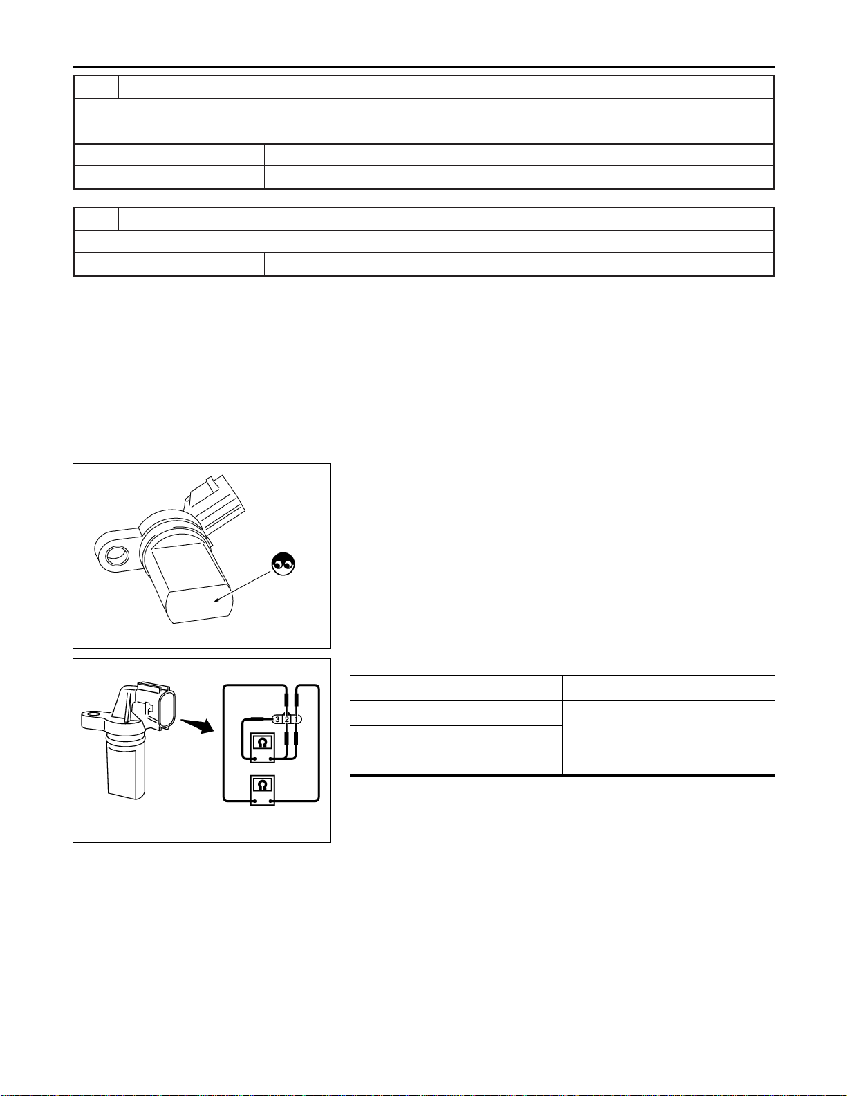
10 CHECK GEAR TOOTH
Visually check for chipping signal plate gear tooth.
OK or NG
OK © GO TO 11.
NG © Replace the signal plate.
11 CHECK INTERMITTENT INCIDENT
Refer to “TROUBLE DIAGNOSIS FOR INTERMITTENT INCIDENT”, EC-156.
© INSPECTION END
PBIB0563E
Component Inspection
NFEC1415
CRANKSHAFT POSITION SENSOR (POS)
NFEC1415S01
1. Loosen the fixing bolt of the sensor.
2. Disconnect crankshaft position sensor (POS) harness connec-
tor.
3. Remove the sensor.
4. Visually check the sensor for chipping.
SEC173D
5. Check resistance as shown in the figure.
Terminal No. (Polarity) Resistance Ω [at 25°C (77°F)]
1 (+) - 2 (−)
Except 0 or ∞1 (+) - 3 (−)
2 (+) - 3 (−)
DTC P0335 CKP SENSOR (POS)
Diagnostic Procedure (Cont’d)
EC-336
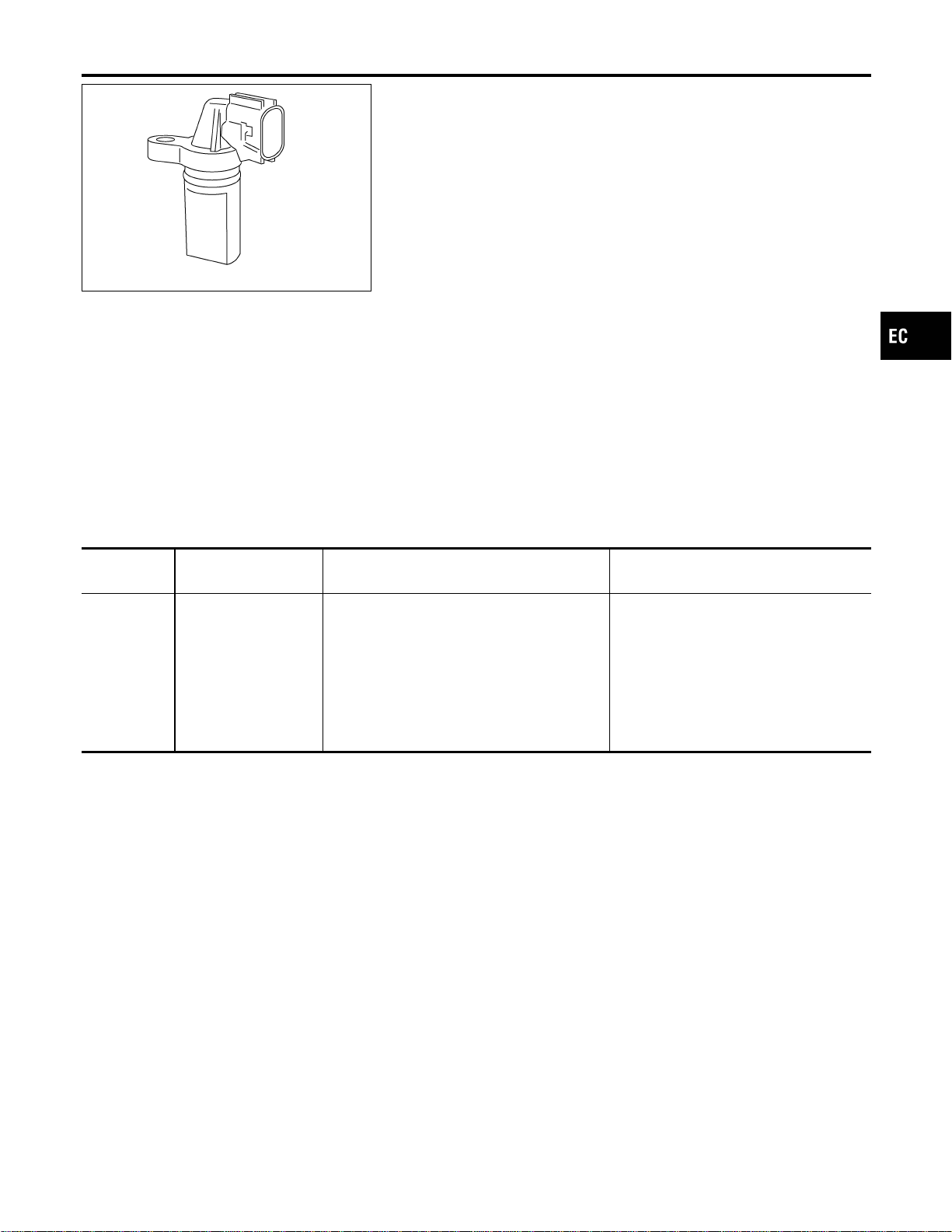
PBIB0562E
Component Description
NFEC0945
The camshaft position sensor (PHASE) senses the retraction with
intake valve camshaft to identify a particular cylinder. The crank-
shaft position sensor (POS) senses the piston position. When the
crankshaft position sensor (POS) system becomes inoperative, the
camshaft position sensor (PHASE) provides various controls of
engine parts instead, utilizing timing of cylinder identification sig-
nals. The sensor consists of a permanent magnet and Hall IC.
When engine is running, the high and low parts of the teeth cause
the gap with the sensor to change. The changing gap causes the
magnetic field near the sensor to change. Due to the changing
magnetic field, the voltage from the sensor changes.
On Board Diagnosis Logic
NFEC0947
DTC No.
Trouble diagnosis
name
DTC Detecting Condition Possible Cause
P0340
0340
(Bank 1)
P0345
0345
(Bank 2)
Camshaft position sen-
sor circuit
I The cylinder No. signal is not sent to ECM
for the first few seconds during engine
cranking.
I The cylinder No. signal is not sent to ECM
during engine running.
I The cylinder No. signal is not in the normal
pattern during engine running.
I Harness or connectors
[The camshaft position sensor
(PHASE) circuit is open or shorted.]
I Camshaft position sensor (PHASE)
I Camshaft (Intake)
I Starter motor (Refer to SC section.)
I Starting system circuit (Refer to SC
section.)
I Dead (Weak) battery
DTC Confirmation Procedure
NFEC0948
NOTE:
If “DTC Confirmation Procedure” has been previously conducted,
always turn ignition switch “OFF” and wait at least 10 seconds
before conducting the next test.
TESTING CONDITION:
Before performing the following procedure, confirm that bat-
tery voltage is more than 10.5V with ignition switch “ON”.
GI
MA
EM
LC
FE
CL
MT
AT
AX
SU
BR
ST
RS
BT
HA
SC
EL
IDX
DTC P0340, P0345 CMP SENSOR (PHASE)
Component Description
EC-337
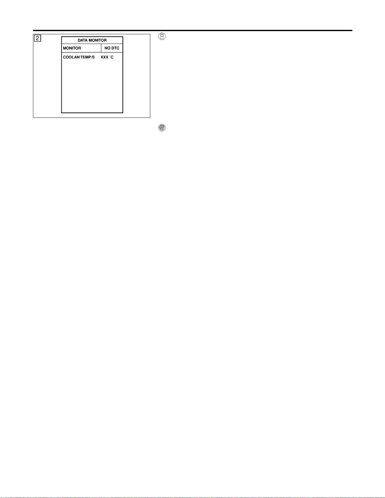
SEF013Y
WITH CONSULT-II
NFEC0948S03
1) Turn ignition switch “ON”.
2) Select “DATA MONITOR” mode with CONSULT-II.
3) Crank engine for at least 2 seconds and run it for at least 5
seconds at idle speed.
4) If 1st trip DTC is detected, go to “Diagnostic Procedure”,
EC-342. If 1st trip DTC is not detected, go to next step.
5) Maintaining engine speed at more than 1,000 rpm for at least
5 seconds.
6) If 1st trip DTC is detected, go to “Diagnostic Procedure”,
EC-342.
WITH GST
NFEC0948S04
Follow the procedure “With CONSULT-II” above.
DTC P0340, P0345 CMP SENSOR (PHASE)
DTC Confirmation Procedure (Cont’d)
EC-338
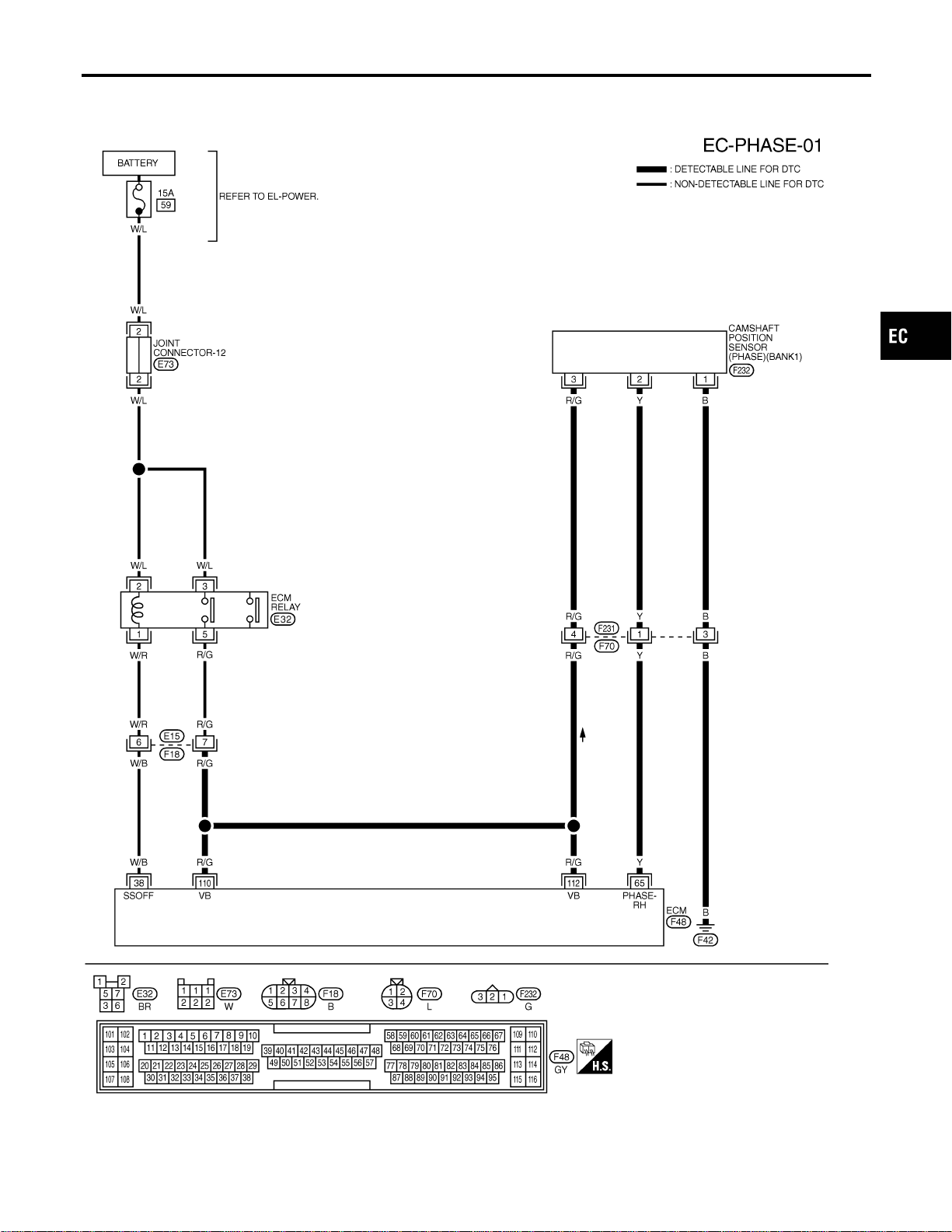
Wiring Diagram
NFEC0949
BANK 1
NFEC0949S01
MEC507D
GI
MA
EM
LC
FE
CL
MT
AT
AX
SU
BR
ST
RS
BT
HA
SC
EL
IDX
DTC P0340, P0345 CMP SENSOR (PHASE)
Wiring Diagram
EC-339
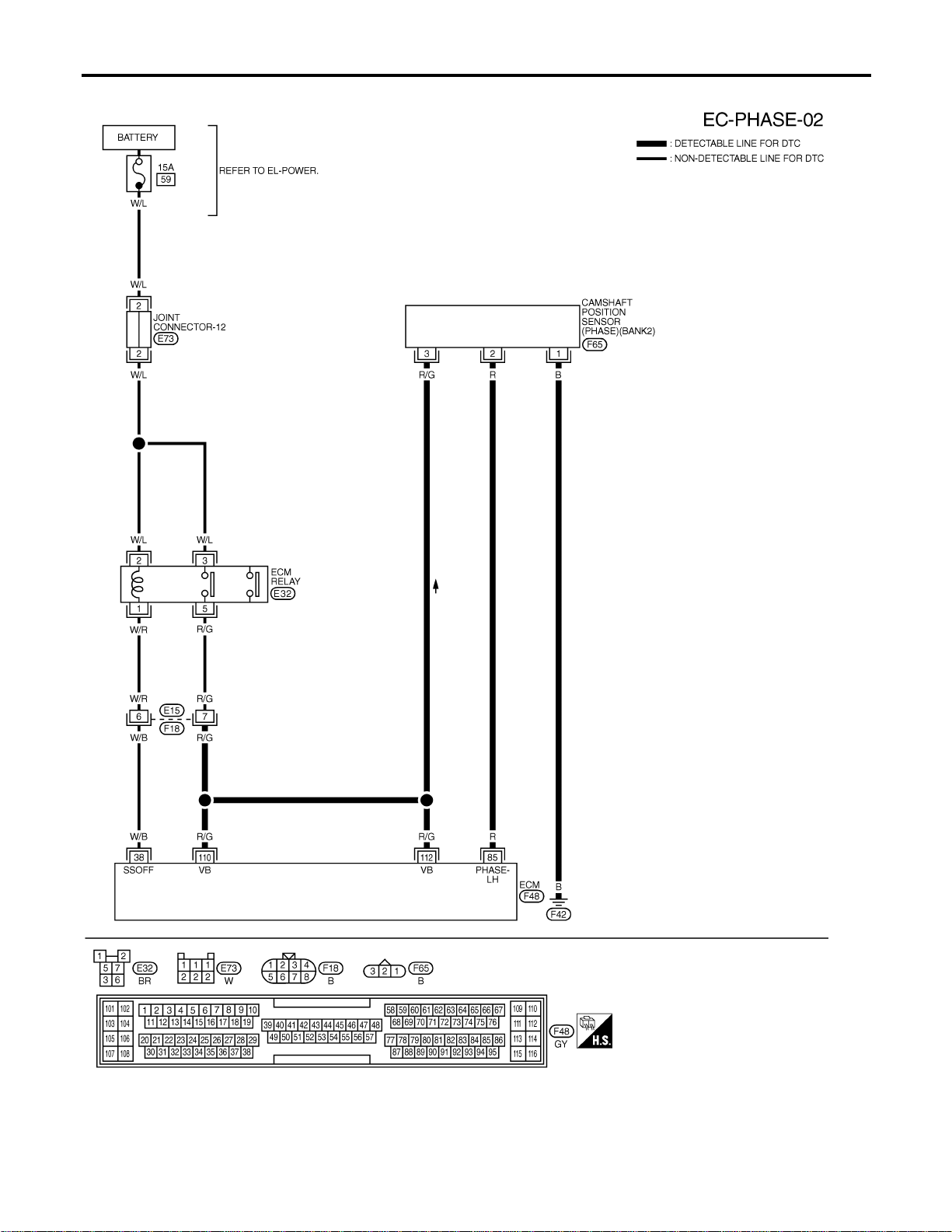
BANK 2
NFEC0949S02
MEC506D
DTC P0340, P0345 CMP SENSOR (PHASE)
Wiring Diagram (Cont’d)
EC-340
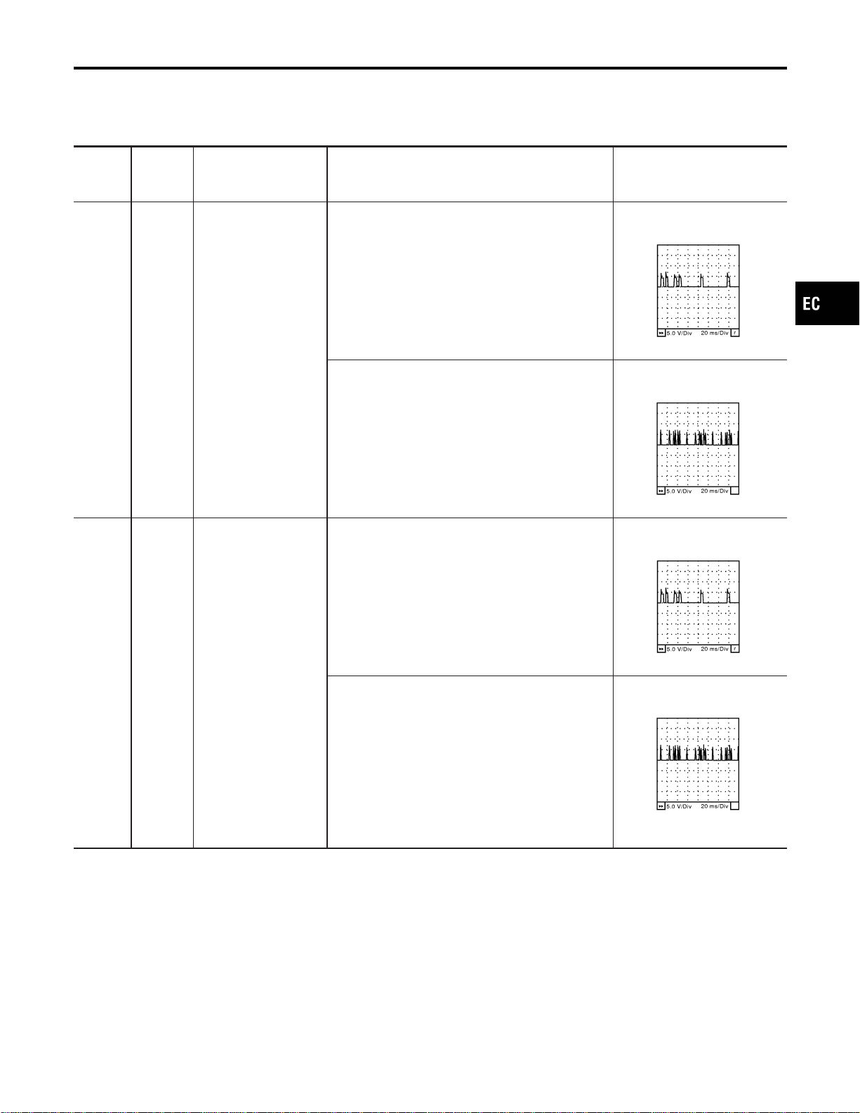
Specification data are reference values and are measured between each terminal and ground.
CAUTION:
Do not use ECM ground terminals when measuring input/output voltage. Doing so may result in dam-
age to the ECM’s transistor. Use a ground other than ECM terminals, such as the ground.
TERMI-
NAL
NO.
WIRE
COLOR
ITEM CONDITION DATA (DC Voltage)
65 Y
Camshaft position sen-
sor (PHASE) (Bank 1)
[Engine is running]
I Warm-up condition
I Idle speed
BATTERY VOLTAGE
(11 - 14V)★
SEC033D
[Engine is running]
I Warm-up condition
I Engine speed is 2,000 rpm.
BATTERY VOLTAGE
(11 - 14V)★
SEC034D
85 R
Camshaft position sen-
sor (PHASE) (Bank 2)
[Engine is running]
I Warm-up condition
I Idle speed
BATTERY VOLTAGE
(11 - 14V)★
SEC033D
[Engine is running]
I Warm-up condition
I Engine speed is 2,000 rpm.
BATTERY VOLTAGE
(11 - 14V)★
SEC034D
★: Average voltage for pulse signal (Actual pulse signal can be confirmed by oscilloscope.)
GI
MA
EM
LC
FE
CL
MT
AT
AX
SU
BR
ST
RS
BT
HA
SC
EL
IDX
DTC P0340, P0345 CMP SENSOR (PHASE)
Wiring Diagram (Cont’d)
EC-341
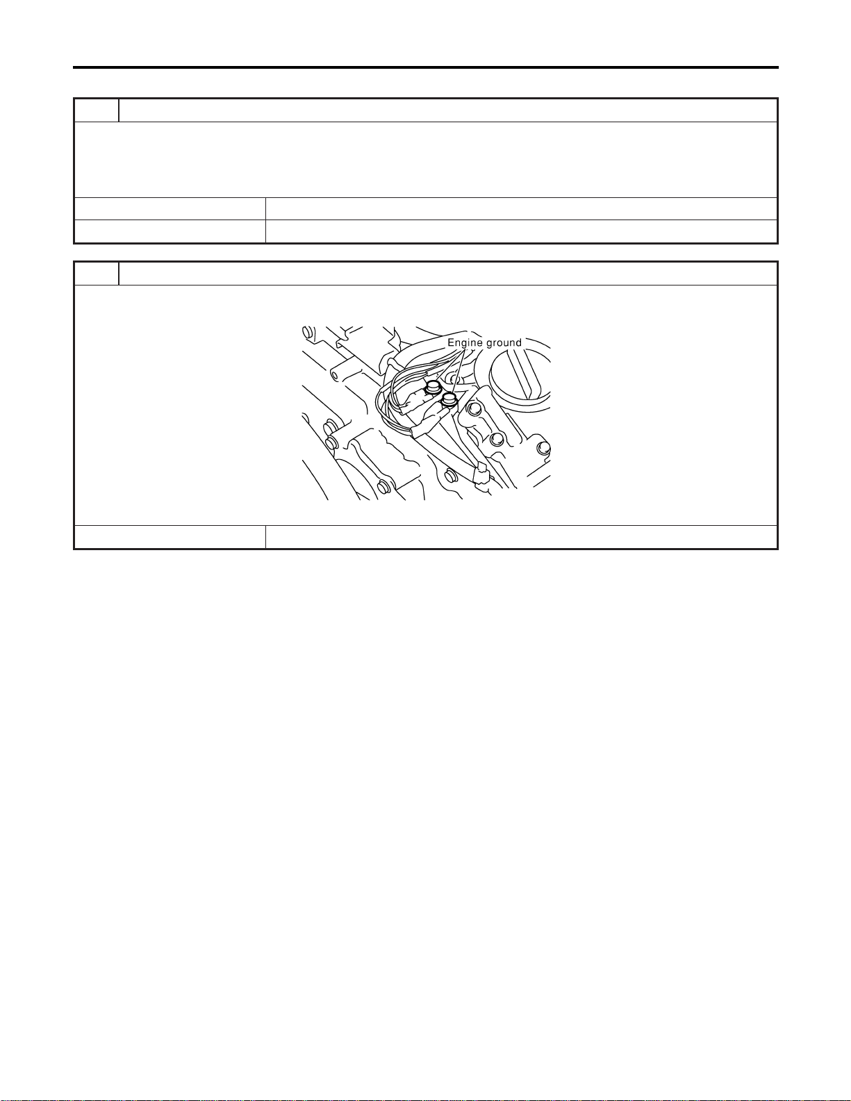
Diagnostic Procedure
NFEC0950
1 CHECK STARTING SYSTEM
Turn ignition switch to “START” position.
Does the engine turn over?
Does the starter motor operate?
YesorNo
Yes © GO TO 2.
No © Check starting system. (Refer to SC-10, “STARTING SYSTEM”.)
2 RETIGHTEN GROUND SCREWS
1. Turn ignition switch “OFF”.
2. Loosen and retighten engine ground screws.
SEC047D
© GO TO 3.
DTC P0340, P0345 CMP SENSOR (PHASE)
Diagnostic Procedure
EC-342
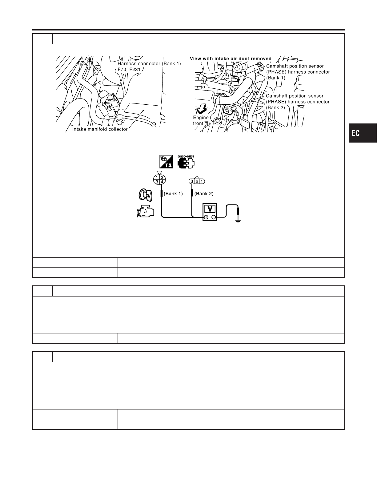
3 CHECK CMP SENSOR (PHASE) POWER SUPPLY CIRCUIT
1. Disconnect CMP sensor (PHASE) harness connector (bank 2) or harness connectors F70, F231 (bank 1).
SEC122D
2. Check voltage between CMP sensor (PHASE) harness connector (bank 2) terminal 3 or harness connector F70 (bank
1) terminal 4 and ground with CONSULT-II or tester.
SEC206D
Voltage: Battery voltage
3. Also check harness for short to ground and short to power.
OK or NG
OK © GO TO 5.
NG © GO TO 4.
4 DETECT MALFUNCTIONING PART
Check the following.
I Harness connectors F70, F231 (bank 1)
I Harness connectors E15, F18
I Harness for open or short between ECM and camshaft position sensor (PHASE) or harness connector F70
I Harness for open or short between ECM relay and camshaft position sensor (PHASE) or harness connector F70
© Repair open circuit or short to ground or short to power in harness or connectors.
5 CHECK CMP SENSOR (PHASE) GROUND CIRCUIT FOR OPEN AND SHORT
1. Check harness continuity between harness connector F70 terminal 3 and engine ground (bank 1). Refer to Wiring Dia-
gram.
2. Check CMP sensor (PHASE) harness connector terminal 1 and engine ground (bank 2). Refer to Wiring Diagram.
Continuity should exist.
3. Also check harness for short to power.
OK or NG
OK © GO TO 7.
NG © GO TO 6.
GI
MA
EM
LC
FE
CL
MT
AT
AX
SU
BR
ST
RS
BT
HA
SC
EL
IDX
DTC P0340, P0345 CMP SENSOR (PHASE)
Diagnostic Procedure (Cont’d)
EC-343
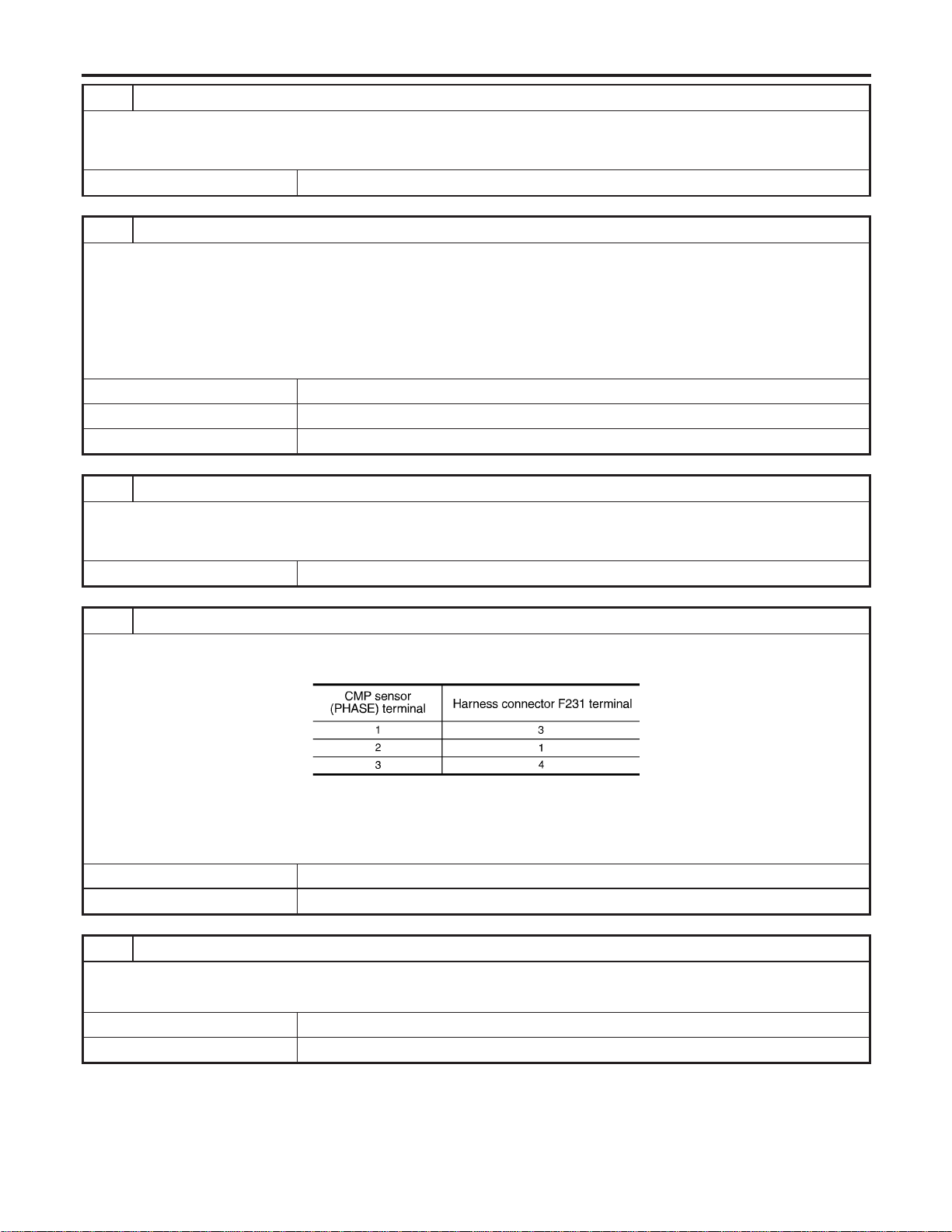
6 DETECT MALFUNCTIONING PART
Check the following.
I Harness connectors F70, F231 (bank 1)
I Harness for open between camshaft position sensor (PHASE) or harness connector F70 and ground
© Repair open circuit or short to ground or short to power in harness or connectors.
7 CHECK CMP SENSOR (PHASE) INPUT SIGNAL CIRCUIT FOR OPEN AND SHORT
1. Disconnect ECM harness connector.
2. Check harness continuity between ECM terminal 65 and harness connector F70 terminal 1.
3. Check harness continuity between ECM terminal 85 and CMP sensor (PHASE) harness connector terminal 2.
Refer to Wiring Diagram.
Continuity should exist.
4. Also check harness for short to ground and short to power.
OK or NG
OK (DTC P0340) © GO TO 9.
OK (DTC P0345) © GO TO 10.
NG © GO TO 8.
8 DETECT MALFUNCTIONING PART
Check the following.
I Harness connectors F70, F231 (bank 1)
I Harness for open or short between ECM and camshaft position sensor (PHASE) or harness connector F70
© Repair open circuit or short to ground or short to power in harness or connectors.
9 CHECK CMP SENSOR (PHASE) SUB-HARNESS CIRCUIT FOR OPEN AND SHORT
1. Disconnect CMP sensor (PHASE) harness connector.
2. Check harness continuity between CMP sensor (PHASE) terminals and harness connector F231 terminals as follows.
MTBL1192
Continuity should exist.
3. Also check harness for short to ground and short to power.
OK or NG
OK © GO TO 10.
NG © Repair open circuit or short to ground or short to power in harness or connectors.
10 CHECK CAMSHAFT POSITION SENSOR (PHASE)
Refer to “Component Inspection”, EC-345.
OK or NG
OK © GO TO 11.
NG © Replace camshaft position sensor (PHASE).
DTC P0340, P0345 CMP SENSOR (PHASE)
Diagnostic Procedure (Cont’d)
EC-344
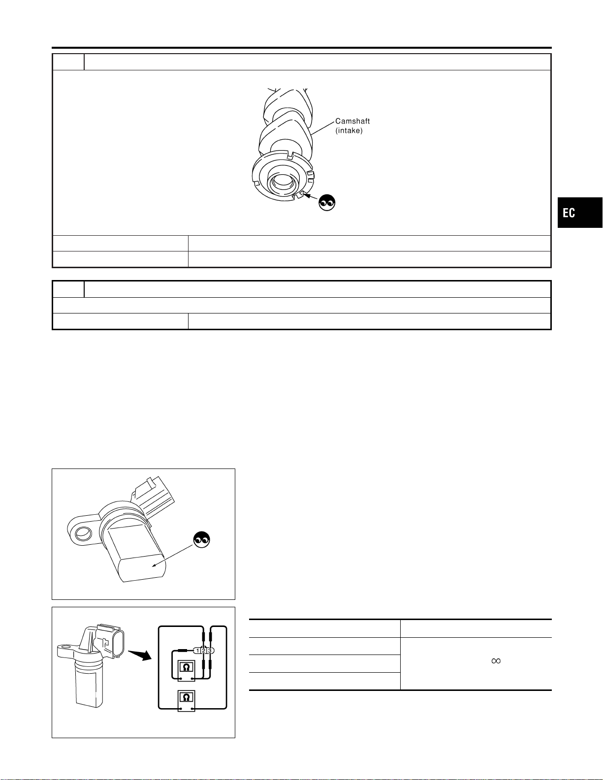
11 CHECK CAMSHAFT (INTAKE)
Visually check for chipped signal plate at camshaft rear.
SEC905C
OK or NG
OK © GO TO 12.
NG © Replace camshaft.
12 CHECK INTERMITTENT INCIDENT
Refer to “TROUBLE DIAGNOSIS FOR INTERMITTENT INCIDENT”, EC-156.
© INSPECTION END
PBIB0563E
Component Inspection
NFEC1416
CAMSHAFT POSITION SENSOR (PHASE)
NFEC1416S01
1. Loosen the fixing bolt of the sensor.
2. Disconnect camshaft position sensor (PHASE) harness con-
nector.
3. Remove the sensor.
4. Visually check the sensor for chipping.
PBIB0564E
5. Check resistance as shown inthe figure.
Terminal No. (Polarity) Resistance Ω [at 25°C (77°F)]
1 (+) - 2 (−)
Except 0 or
1 (+) - 3 (−)
2 (+) - 3 (−)
GI
MA
EM
LC
FE
CL
MT
AT
AX
SU
BR
ST
RS
BT
HA
SC
EL
IDX
DTC P0340, P0345 CMP SENSOR (PHASE)
Diagnostic Procedure (Cont’d)
EC-345
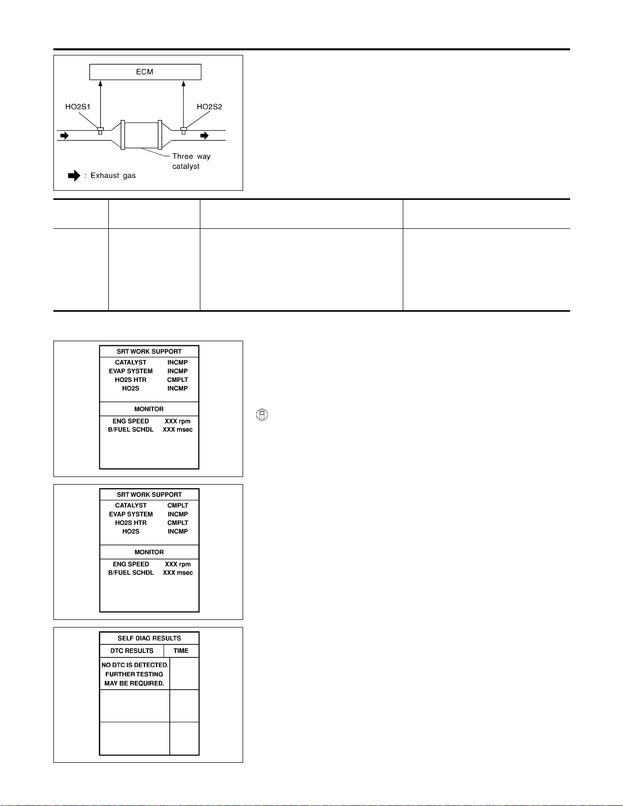
SEF484YD
On Board Diagnosis Logic
NFEC1443
The ECM monitors the switching frequency ratio of heated oxygen
sensors 1 and 2.
A warm-up three way catalyst with high oxygen storage capacity
will indicate a low switching frequency of heated oxygen sensor 2.
As oxygen storage capacity decreases, the heated oxygen sensor
2 switching frequency will increase.
When the frequency ratio of heated oxygen sensors 1 and 2
approaches a specified limit value, the warm-up three way catalyst
malfunction is diagnosed.
DTC No.
Trouble diagnosis
name
DTC Detecting Condition Possible Cause
P0420
0420
(Bank 1)
P0430
0430
(Bank 2)
Catalyst system effi-
ciency below thresh-
old
Warm-up three way catalyst does not operate
properly, warm-up three way catalyst does not
have enough oxygen storage capacity.
I Warm-up three way catalyst
I Exhaust tube
I Intake air leaks
I Injectors
I Injector leaks
I Spark plug
I Improper ignition timing
SEC138D
SEC139D
SEF560X
DTC Confirmation Procedure
NFEC0952
NOTE:
If “DTC Confirmation Procedure” has been previously conducted,
always turn ignition switch “OFF” and wait at least 10 seconds
before conducting the next test.
WITH CONSULT-II
NFEC0952S01
TESTING CONDITION:
I Open engine hood before conducting the following proce-
dure.
I Do not hold engine speed for more than the specified
minutes below.
1) Turn ignition switch “ON”.
2) Select “DTC & SRT CONFIRMATION” then “SRT WORK SUP-
PORT” mode with CONSULT-II.
3) Start engine.
4) Rev engine up to 3,000±500 rpm and hold it for 3 consecutive
minutes then release the accelerator pedal completely.
5) Wait 5 seconds at idle.
6) Rev engine up to 2,500±500 rpm and maintain it until “INCMP”
of CATALYST changes to “CMPLT” (It will take approximately
5 minutes).
If not “CMPLT”, stop engine and cool it down to less than 70°C
(158°F) and then retest from step 1.
7) Select “SELF-DIAG RESULTS” mode with CONSULT-II.
8) Confirm that the 1st trip DTC is not detected.
If the 1st trip DTC is detected, go to “Diagnostic Procedure”,
EC-347.
DTC P0420, P0430 THREE WAY CATALYST FUNCTION
On Board Diagnosis Logic
EC-346
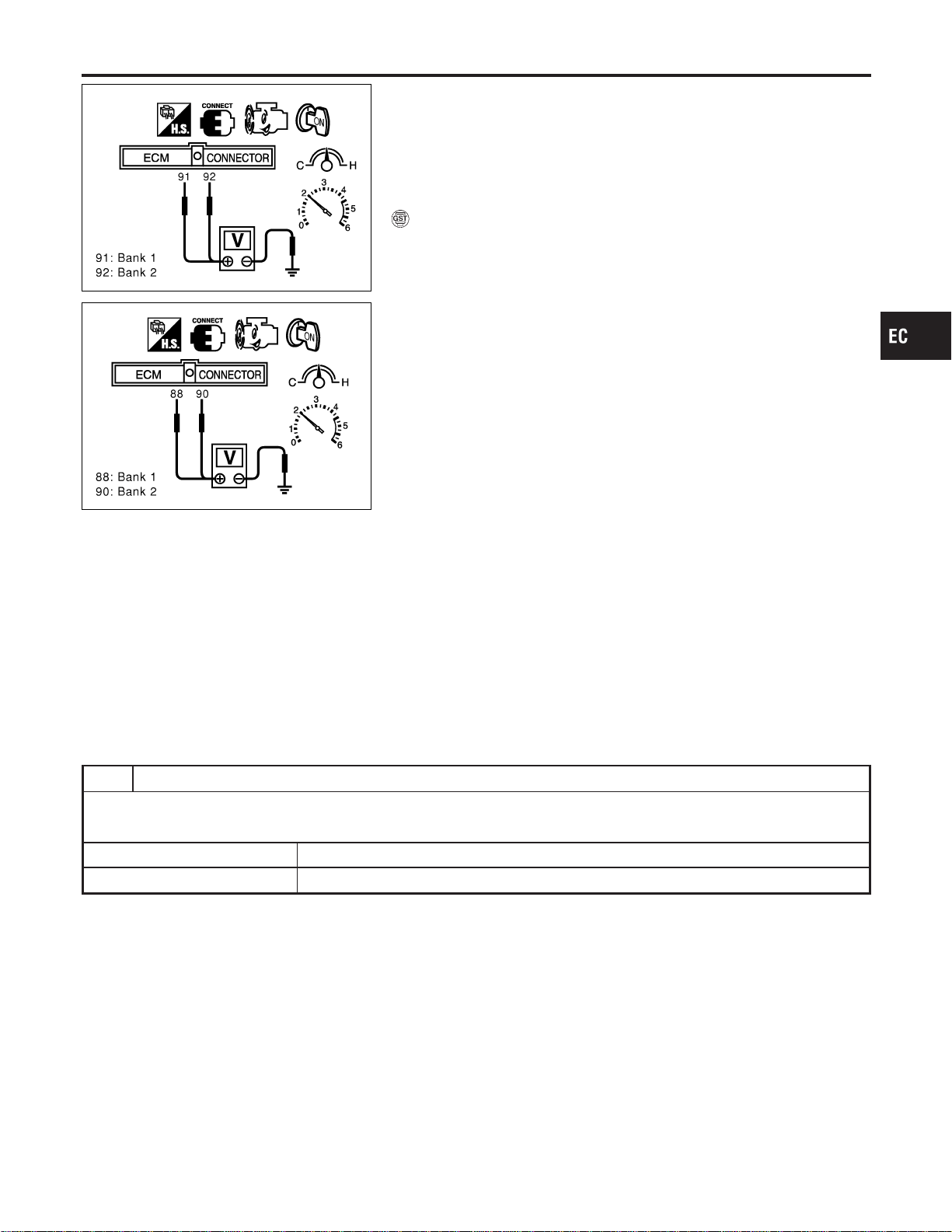
SEC902C
SEC903C
Overall Function Check
NFEC0953
Use this procedure to check the overall function of the warm-up
three way catalyst. During this check, a 1st trip DTC might not be
confirmed.
CAUTION:
Always drive vehicle at a safe speed.
WITH GST
NFEC0953S01
1) Start engine and drive vehicle at a speed of more than 70 km/h
(43 MPH) for 2 consecutive minutes.
2) Stop vehicle with engine running.
3) Set voltmeters probes between ECM terminals 91 [heated oxy-
gen sensor 1 bank 1 signal], 92 [heated oxygen sensor 1 bank
2 signal] and engine ground, and ECM terminals 88 [heated
oxygen sensor 2 bank 1 signal], 90 [heated oxygen sensor 2
bank 2 signal] and engine ground.
4) Keep engine speed at 2,000 rpm constant under no load.
5) Make sure that the voltage switching frequency (high & low)
between ECM terminals 88 and engine ground, or 90 and
engine ground is very less than that of ECM terminals 91 and
engine ground, or 91 and engine ground.
Switching frequency ratio = A/B
A: Heated oxygen sensor 2 voltage switching frequency
B: Heated oxygen sensor 1 voltage switching frequency
This ratio should be less than 0.75.
If the ratio is greater than above, it means warm-up three way
catalyst does not operate properly. Go to “Diagnostic
Procedure”, EC-347.
NOTE:
If the voltage at terminal 92 or 91 does not switch periodically more
than 5 times within 10 seconds at step 5, perform trouble diagno-
sis for “DTC P0133, P0153” first. (See EC-228.)
Diagnostic Procedure
NFEC0954
1 CHECK EXHAUST SYSTEM
Visually check exhaust tubes and muffler for dent.
OK or NG
OK © GO TO 2.
NG © Repair or replace.
GI
MA
EM
LC
FE
CL
MT
AT
AX
SU
BR
ST
RS
BT
HA
SC
EL
IDX
DTC P0420, P0430 THREE WAY CATALYST FUNCTION
Overall Function Check
EC-347
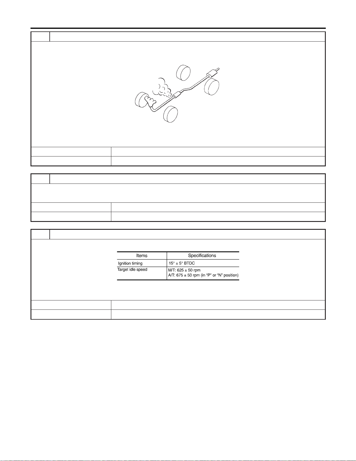
2 CHECK EXHAUST AIR LEAK
1. Start engine and run it at idle.
2. Listen for an exhaust air leak before the warm-up three way catalyst.
SEF099P
OK or NG
OK © GO TO 3.
NG © Repair or replace.
3 CHECK INTAKE AIR LEAK
Listen for an intake air leak after the mass air flow sensor.
OK or NG
OK © GO TO 4.
NG © Repair or replace.
4 CHECK IGNITION TIMING
Check the following items. Refer to “Basic Inspection”, EC-123.
MTBL1186
OK or NG
OK © GO TO 5.
NG © Follow the “Basic Inspection”.
DTC P0420, P0430 THREE WAY CATALYST FUNCTION
Diagnostic Procedure (Cont’d)
EC-348
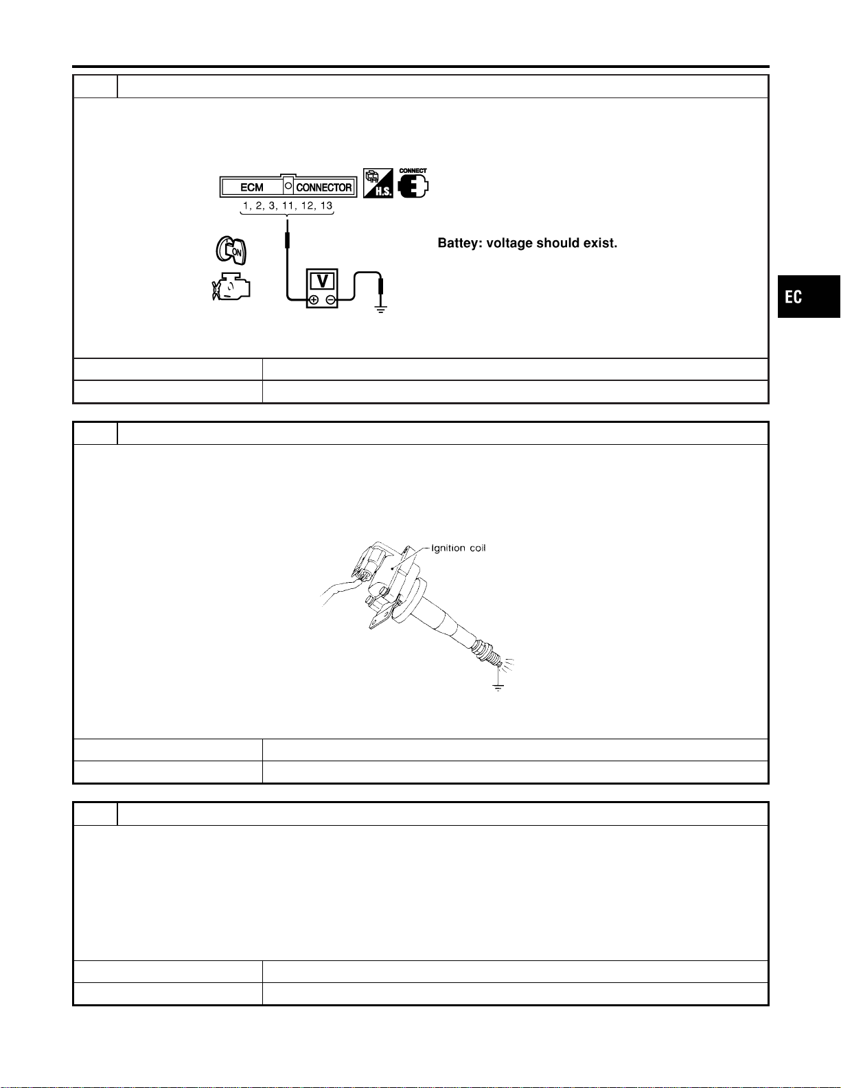
5 CHECK INJECTORS
1. Refer to WIRING DIAGRAM for Injectors, EC-704.
2. Stop engine and then turn ignition switch “ON”.
3. Check voltage between ECM terminals 1, 2, 3, 11, 12, 13 and ground with CONSULT-II or tester.
SEC124D
OK or NG
OK © GO TO 6.
NG © Perform “Diagnostic Procedure”, “INJECTOR”, EC-705.
6 CHECK IGNITION SPARK
1. Turn ignition switch “OFF”.
2. Disconnect ignition coil assembly from rocker cover.
3. Connect a known good spark plug to the ignition coil assembly.
4. Place end of spark plug against a suitable ground and crank engine.
5. Check for spark.
SEF575Q
OK or NG
OK © GO TO 7.
NG © Check ignition coil with power transistor and their circuit. Refer to EC-692.
7 CHECK INJECTOR
1. Turn ignition switch “OFF”.
2. Remove injector assembly.
Refer to EC-57.
Keep fuel hose and all injectors connected to injector gallery.
3. Disconnect all ignition coil harness connectors.
4. Turn ignition switch “ON”.
Make sure fuel does not drip from injector.
OK or NG
OK (Does not drip.) © GO TO 8.
NG (Drips.) © Replace the injector(s) from which fuel is dripping.
GI
MA
EM
LC
FE
CL
MT
AT
AX
SU
BR
ST
RS
BT
HA
SC
EL
IDX
DTC P0420, P0430 THREE WAY CATALYST FUNCTION
Diagnostic Procedure (Cont’d)
EC-349

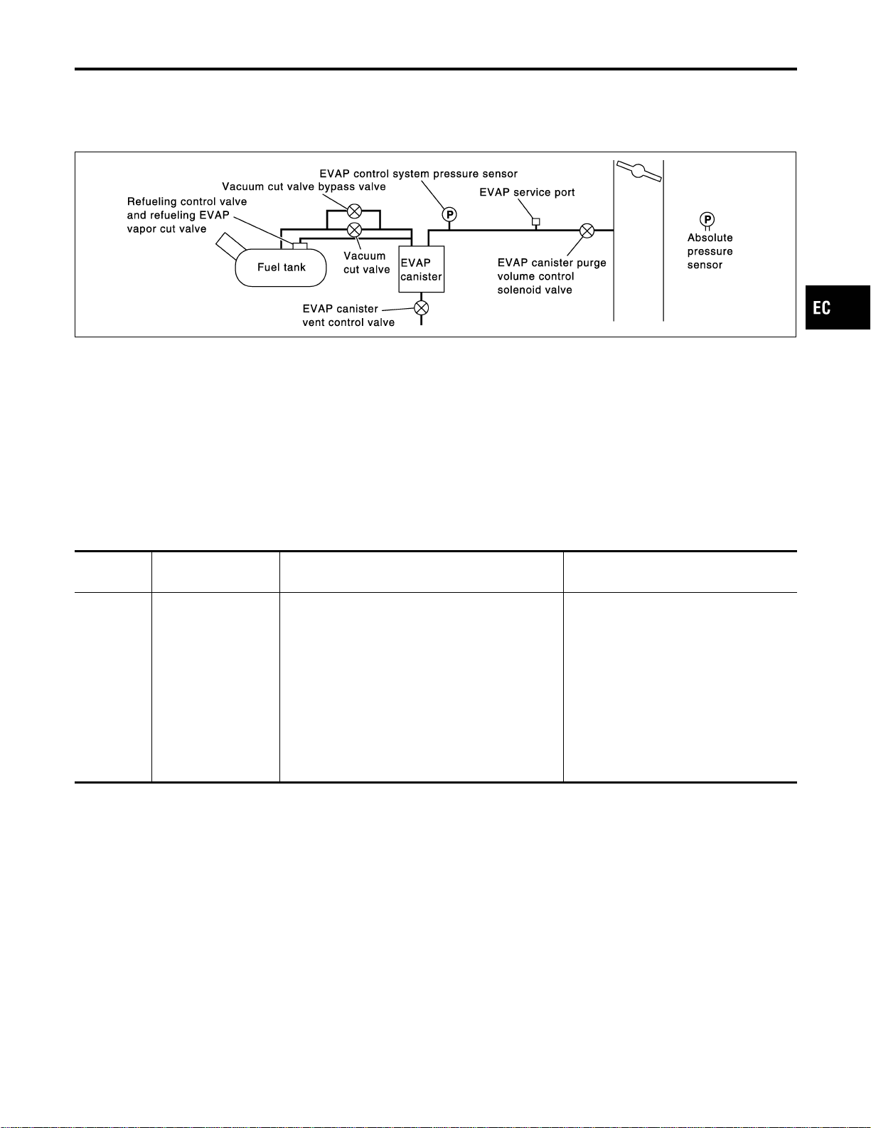
System Description
NFEC0955
NOTE:
If DTC P0441 is displayed with P0121, P0122, P0123, P0226, P0227, P0228, P1227 or P1228, perform
trouble diagnosis for other DTC.
SEC936C
In this evaporative emission (EVAP) control system, purge flow occurs during non-closed throttle conditions.
Purge volume is related to air intake volume. Under normal purge conditions (non-closed throttle), the EVAP
canister purge volume control solenoid valve is open to admit purge flow. Purge flow exposes the EVAP con-
trol system pressure sensor to intake manifold vacuum.
On Board Diagnosis Logic
NFEC0956
Under normal conditions (non-closed throttle), sensor output volt-
age indicates if pressure drop and purge flow are adequate. If not,
a fault is determined.
DTC No.
Trouble diagnosis
name
DTC Detecting Condition Possible Cause
P0441
0441
EVAP control system
incorrect purge flow
EVAP control system does not operate properly,
EVAP control system has a leak between intake
manifold and EVAP control system pressure sen-
sor.
I EVAP canister purge volume control
solenoid valve stuck closed
I EVAP control system pressure sensor
and the circuit
I Loose, disconnected or improper con-
nection of rubber tube
I Blocked rubber tube
I Cracked EVAP canister
I EVAP canister purge volume control
solenoid valve circuit
I Blocked purge port
I EVAP canister vent control valve
GI
MA
EM
LC
FE
CL
MT
AT
AX
SU
BR
ST
RS
BT
HA
SC
EL
IDX
DTC P0441 EVAP CONTROL SYSTEM
System Description
EC-351
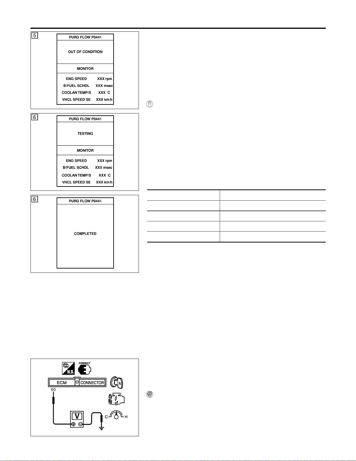
SEC140D
DTC Confirmation Procedure
NFEC0957
SEC141D
SEC759C
CAUTION:
Always drive vehicle at a safe speed.
NOTE:
If “DTC Confirmation Procedure” has been previously conducted,
always turn ignition switch “OFF” and wait at least 10 seconds
before conducting the next test.
TESTING CONDITION:
Always perform test at a temperature of 5°C (41°F) or more.
WITH CONSULT-II
NFEC0957S01
1) Start engine and warm it up to normal operating temperature.
2) Turn ignition switch “OFF” and wait at least 10 seconds.
3) Start engine and let it idle for at least 70 seconds.
4) Select “PURG FLOW P0441” of “EVAPORATIVE SYSTEM” in
“DTC CONFIRMATION” mode with CONSULT-II.
5) Touch “START”.
If “COMPLETED” is displayed, go to step 7.
6) When the following conditions are met, “TESTING” will be dis-
played on the CONSULT-II screen. Maintain the conditions
continuously until “TESTING” changes to “COMPLETED”. (It
will take at least 35 seconds.)
Selector lever Suitable position
Vehicle speed 32 - 120 km/h (20 - 75 MPH)
ENG SPEED 500 - 3,000 rpm
B/FUEL SCHDL 1.3 - 8.1 msec
Engine coolant temperature 70 - 100°C (158 - 212°F)
If “TESTING” is not changed for a long time, retry from
step 2.
7) Make sure that “OK” is displayed after touching “SELF-DIAG
RESULTS”. If “NG” is displayed, refer to “Diagnostic
Procedure”, EC-354.
SEC915C
Overall Function Check
NFEC0958
Use this procedure to check the overall monitoring function of the
EVAP control system purge flow monitoring. During this check, a
1st trip DTC might not be confirmed.
WITH GST
NFEC0958S01
1) Lift up drive wheels.
2) Start engine (TCS switch “OFF”) and warm it up to normal
operating temperature.
3) Turn ignition switch “OFF”, wait at least 10 seconds.
4) Start engine and wait at least 70 seconds.
DTC P0441 EVAP CONTROL SYSTEM
DTC Confirmation Procedure
EC-352
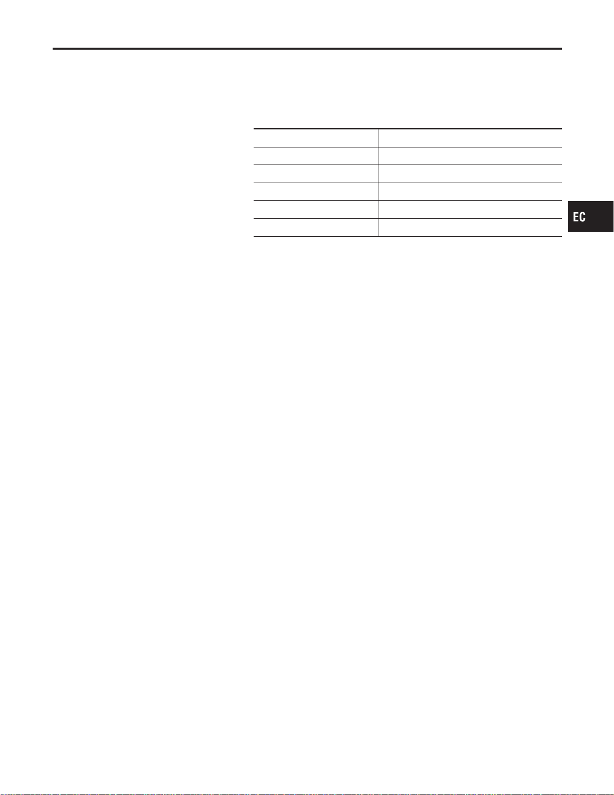
5) Set voltmeter probes to ECM terminals 60 (EVAP control sys-
tem pressure sensor signal) and ground.
6) Check EVAP control system pressure sensor value at idle
speed and note it.
7) Establish and maintain the following conditions for at least 1
minute.
Air conditioner switch ON
Steering wheel Fully turned
Headlamp switch ON
Rear window defogger switch ON
Engine speed Approx. 3,000 rpm
Gear position Any position other than “P”, “N” or “R”
8) Verify that EVAP control system pressure sensor value stays
0.1V less than the value at idle speed (measured at step 6) for
at least 1 second.
9) If NG, go to “Diagnostic Procedure”, EC-354.
GI
MA
EM
LC
FE
CL
MT
AT
AX
SU
BR
ST
RS
BT
HA
SC
EL
IDX
DTC P0441 EVAP CONTROL SYSTEM
Overall Function Check (Cont’d)
EC-353
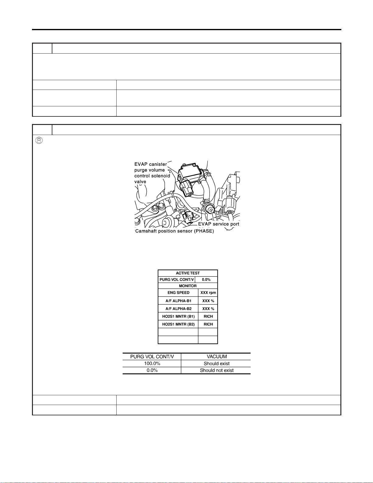
Diagnostic Procedure
=NFEC0959
1 CHECK EVAP CANISTER
1. Turn ignition switch “OFF”.
2. Check EVAP canister for cracks.
OK or NG
OK (With CONSULT-II) © GO TO 2.
OK (Without CONSULT-
II)
© GO TO 3.
NG © Replace EVAP canister.
2 CHECK PURGE FLOW
With CONSULT-II
1. Disconnect vacuum hose connected to EVAP canister purge volume control solenoid valve at EVAP service port and
install vacuum gauge.
SEC929C
2. Start engine and let it idle.
3. Select “PURG VOL CONT/V” in “ACTIVE TEST” mode with CONSULT-II.
4. Rev engine up to 2,000 rpm.
5. Touch “Qd” and “Qu” on CONSULT-II screen to adjust “PURG VOL CONT/V” opening and check vacuum existence.
SEC142D
MTBL1158
OK or NG
OK © GO TO 7.
NG © GO TO 4.
DTC P0441 EVAP CONTROL SYSTEM
Diagnostic Procedure
EC-354
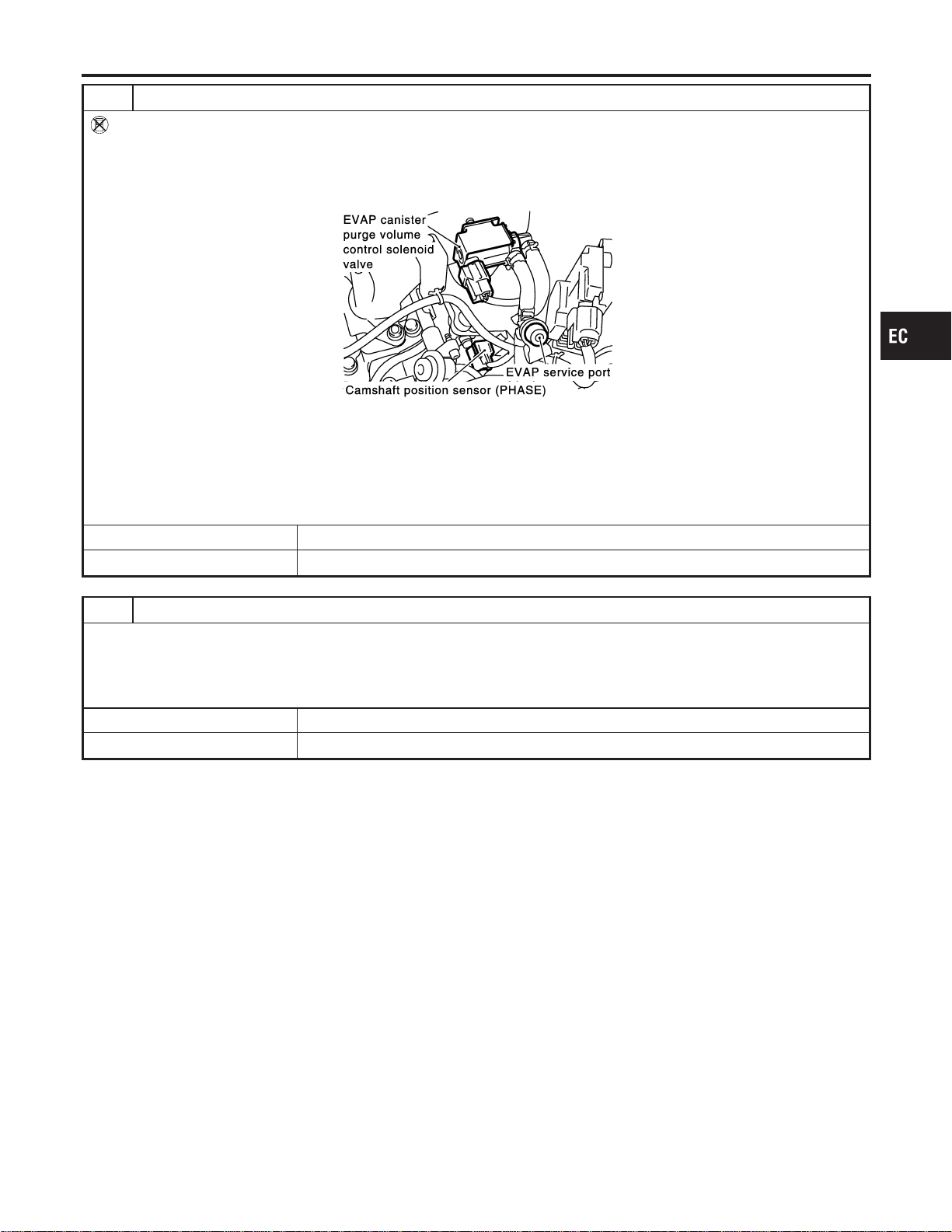
3 CHECK PURGE FLOW
Without CONSULT-II
1. Start engine and warm it up to normal operating temperature.
2. Stop engine.
3. Disconnect vacuum hose connected to EVAP canister purge volume control solenoid valve at EVAP service port and
install vacuum gauge.
SEC929C
4. Start engine and let it idle for at least 80 seconds.
5. Check vacuum gauge indication when revving engine up to 2,000 rpm.
Vacuum should exist.
6. Release the accelerator pedal fully and let idle.
Vacuum should not exist.
OK or NG
OK © GO TO 7.
NG © GO TO 4.
4 CHECK EVAP PURGE LINE
1. Turn ignition switch “OFF”.
2. Check EVAP purge line for improper connection or disconnection.
Refer to “EVAPORATIVE EMISSION LINE DRAWING”, EC-40.
OK or NG
OK © GO TO 5.
NG © Repair it.
GI
MA
EM
LC
FE
CL
MT
AT
AX
SU
BR
ST
RS
BT
HA
SC
EL
IDX
DTC P0441 EVAP CONTROL SYSTEM
Diagnostic Procedure (Cont’d)
EC-355
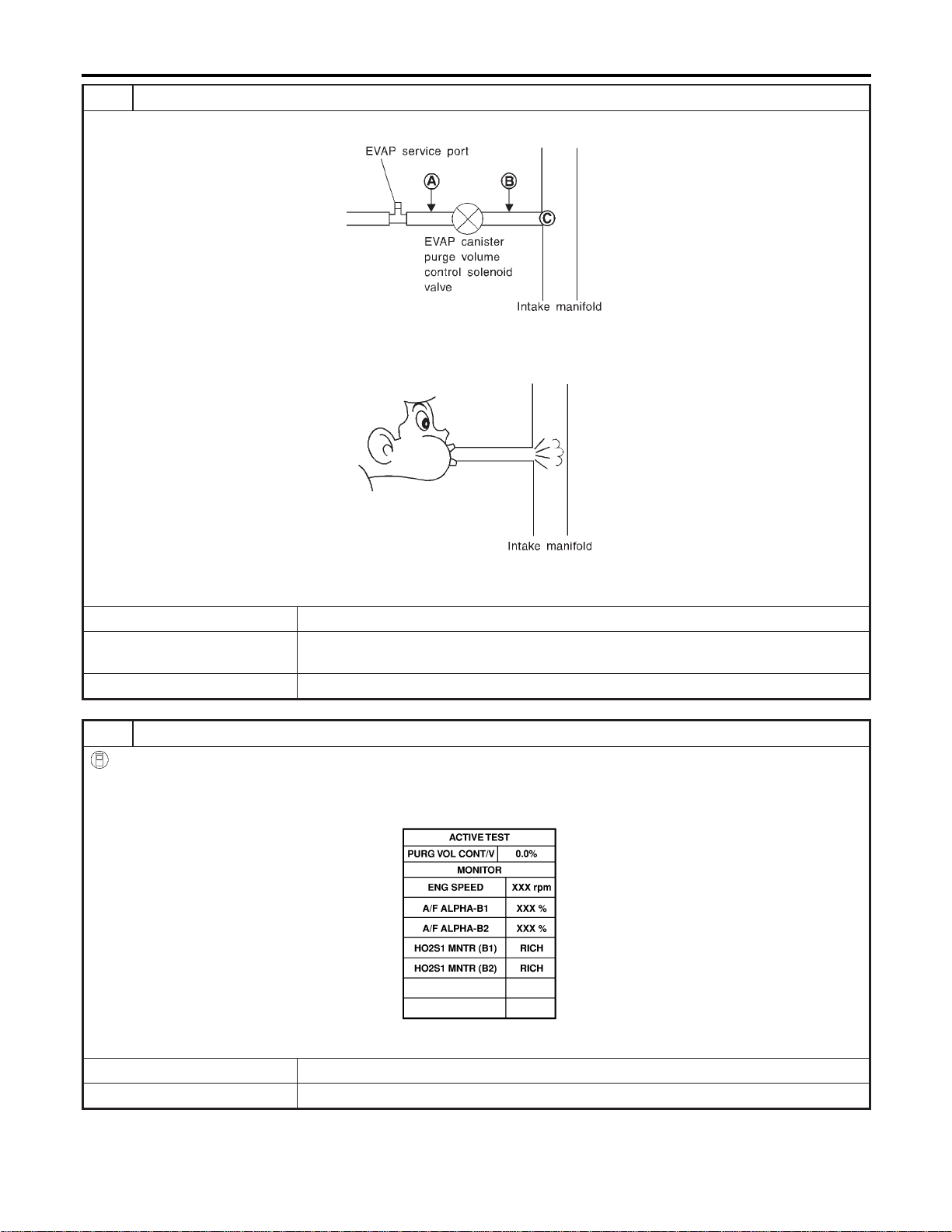
5 CHECK EVAP PURGE HOSE AND PURGE PORT
1. Disconnect purge hoses connected to EVAP service port A and EVAP canister purge volume control solenoid valve B.
SEF367U
2. Blow air into each hose and EVAP purge port C.
3. Check that air flows freely.
SEF368U
OK or NG
OK (With CONSULT-II) © GO TO 6.
OK (Without CONSULT-
II)
© GO TO 7.
NG © Repair or clean hoses and/or purge port.
6 CHECK EVAP CANISTER PURGE VOLUME CONTROL SOLENOID VALVE
With CONSULT-II
1. Start engine.
2. Perform “PURG VOL CONT/V” in “ACTIVE TEST” mode with CONSULT-II. Check that engine speed varies according
to the valve opening.
SEC142D
OK or NG
OK © GO TO 8.
NG © GO TO 7.
DTC P0441 EVAP CONTROL SYSTEM
Diagnostic Procedure (Cont’d)
EC-356
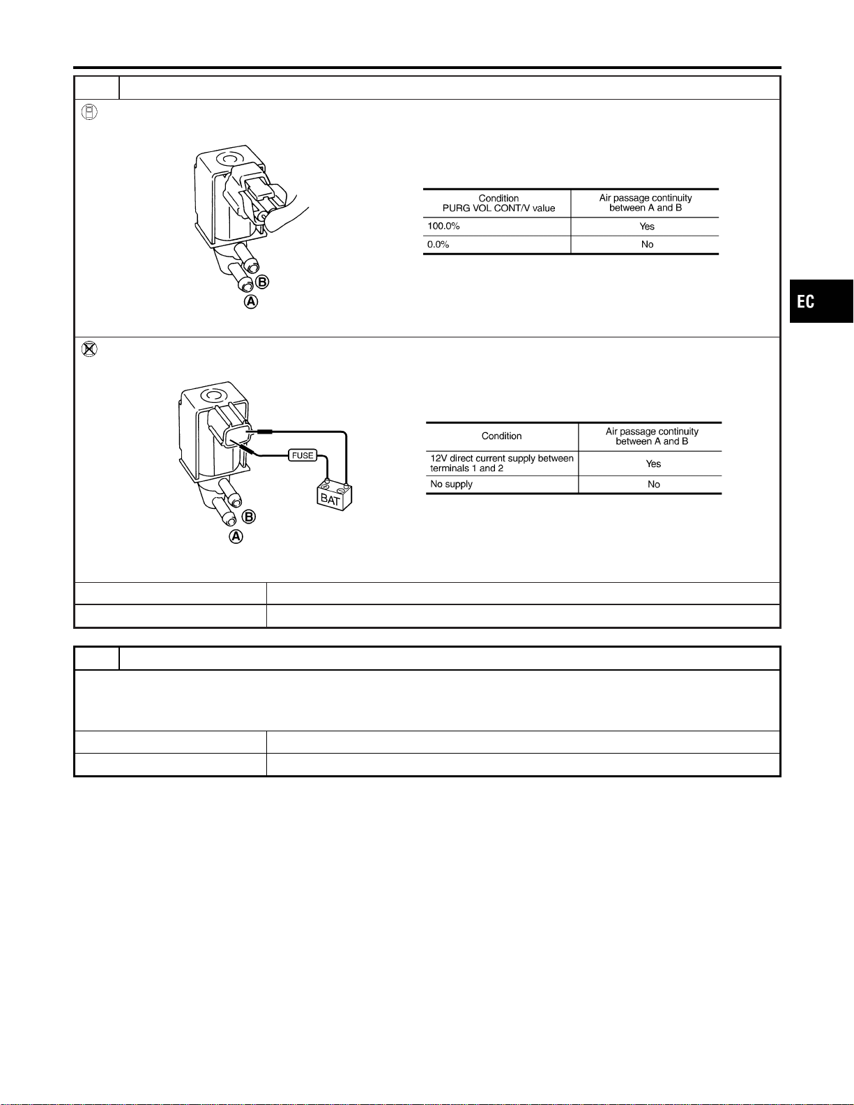
7 CHECK EVAP CANISTER PURGE VOLUME CONTROL SOLENOID VALVE
With CONSULT-II
Check air passage continuity of EVAP canister purge volume control solenoid valve under the following conditions.
SEF334X
Without CONSULT-II
Check air passage continuity of EVAP canister purge volume control solenoid valve under the following conditions.
SEF335X
OK or NG
OK © GO TO 8.
NG © Replace EVAP canister purge volume control solenoid valve.
8 CHECK EVAP CONTROL SYSTEM PRESSURE SENSOR HOSE
1. Turn ignition switch “OFF”.
2. Check disconnection or improper connection of hose connected to EVAP control system pressure sensor.
OK or NG
OK © GO TO 9.
NG © Repair it.
GI
MA
EM
LC
FE
CL
MT
AT
AX
SU
BR
ST
RS
BT
HA
SC
EL
IDX
DTC P0441 EVAP CONTROL SYSTEM
Diagnostic Procedure (Cont’d)
EC-357
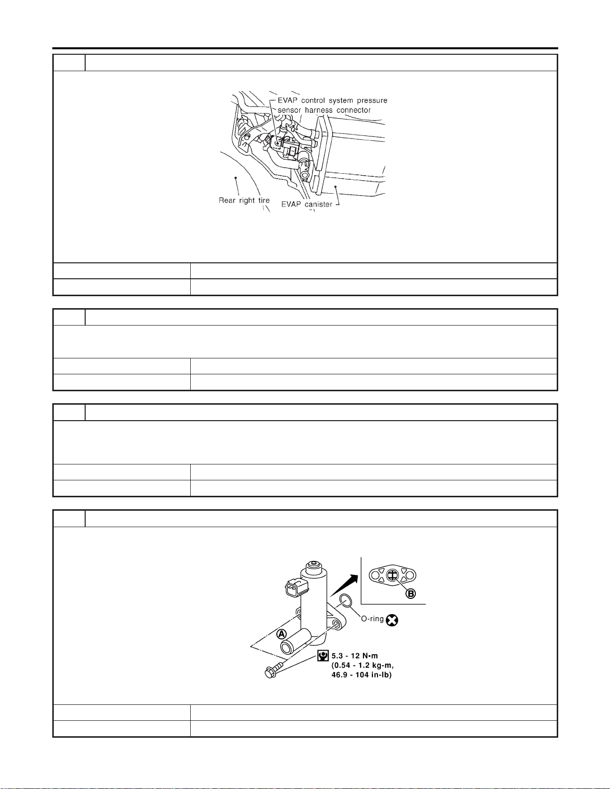
9 CHECK EVAP CONTROL SYSTEM PRESSURE SENSOR CONNECTOR
1. Disconnect EVAP control system pressure sensor harness connector.
SEF495R
2. Check connectors for water.
Water should not exist.
OK or NG
OK © GO TO 10.
NG © Replace EVAP control system pressure sensor.
10 CHECK EVAP CONTROL SYSTEM PRESSURE SENSOR FUNCTION
Refer to “DTC Confirmation Procedure” for DTC P0452, EC-390 and P0453, EC-397.
OK or NG
OK © GO TO 11.
NG © Replace EVAP control system pressure sensor.
11 CHECK RUBBER TUBE FOR CLOGGING
1. Disconnect rubber tube connected to EVAP canister vent control valve.
2. Check the rubber tube for clogging.
OK or NG
OK © GO TO 12.
NG © Clean the rubber tube using an air blower.
12 CHECK EVAP CANISTER VENT CONTROL VALVE-I
1. Remove EVAP canister vent control valve from EVAP canister.
2. Check portion B of EVAP canister vent control valve for being rusted.
SEF376Z
OK or NG
OK © GO TO 13.
NG © Replace EVAP canister vent control valve.
DTC P0441 EVAP CONTROL SYSTEM
Diagnostic Procedure (Cont’d)
EC-358
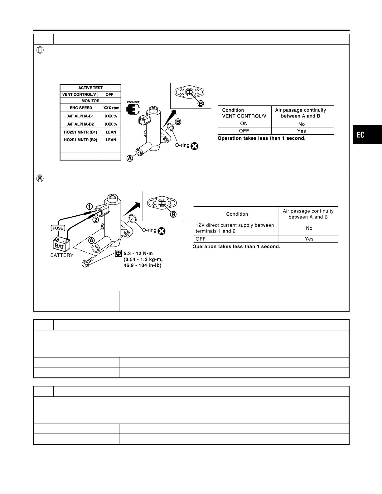
13 CHECK EVAP CANISTER VENT CONTROL VALVE-II
With CONSULT-II
1. Reconnect harness connectors disconnected.
2. Turn ignition switch “ON”.
3. Perform “VENT CONTROL/V” in “ACTIVE TEST” mode.
4. Check air passage continuity and operation delay time.
SEC158D
Without CONSULT-II
Check air passage continuity and operation delay time under the following conditions.
SEF378Z
Make sure new O-ring is installed properly.
OK or NG
OK © GO TO 15.
NG © GO TO 14.
14 CHECK EVAP CANISTER VENT CONTROL VALVE-III
1. Clean the air passage (Portion A to B) of EVAP canister vent control valve using an air blower.
2. Perform Test No. 13 again.
OK or NG
OK © GO TO 15.
NG © Replace EVAP canister vent control valve.
15 CHECK EVAP PURGE LINE
Inspect EVAP purge line (pipe and rubber tube). Check for evidence of leaks.
Refer to “EVAPORATIVE EMISSION LINE DRAWING”, EC-40.
OK or NG
OK © GO TO 16.
NG © Replace it.
GI
MA
EM
LC
FE
CL
MT
AT
AX
SU
BR
ST
RS
BT
HA
SC
EL
IDX
DTC P0441 EVAP CONTROL SYSTEM
Diagnostic Procedure (Cont’d)
EC-359

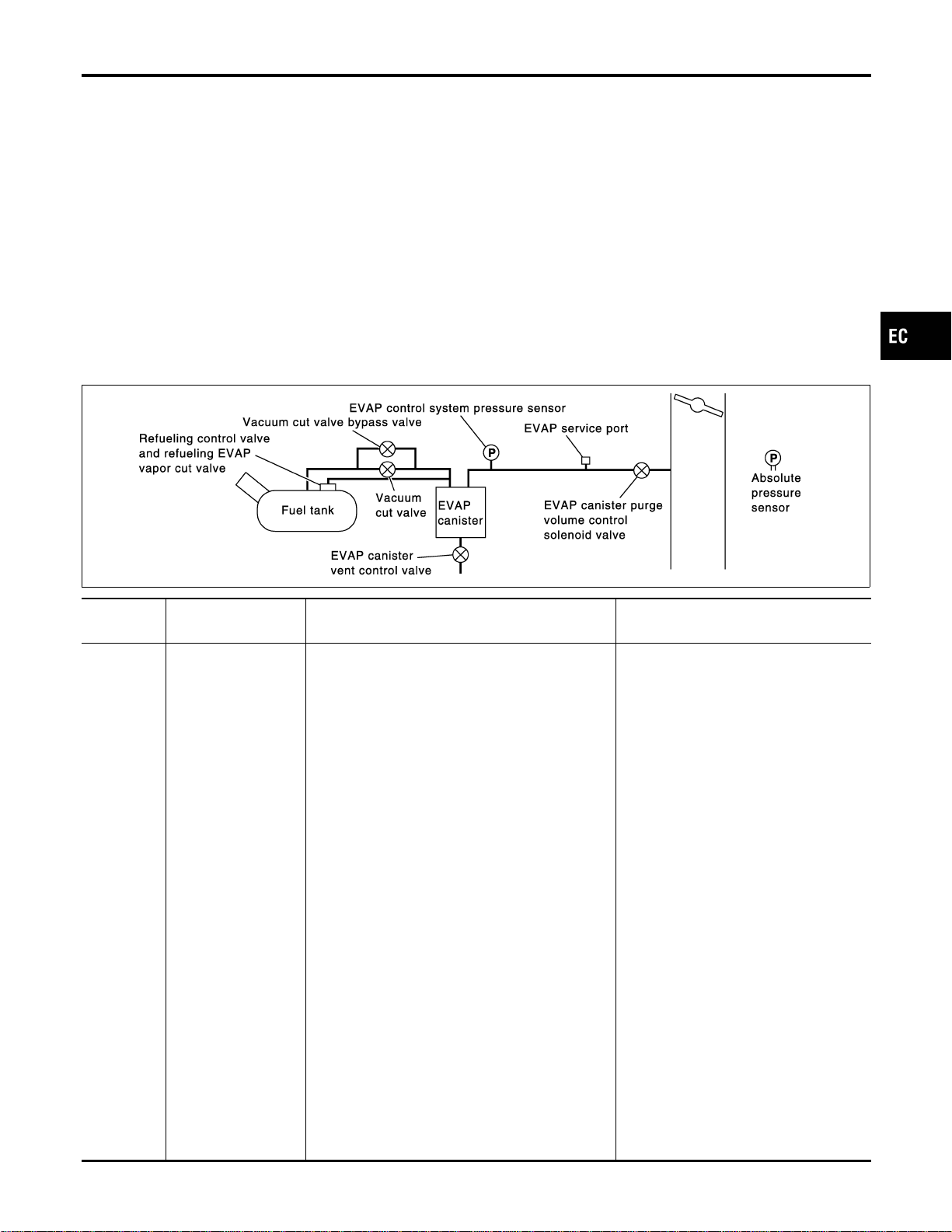
On Board Diagnosis Logic
NFEC0960
NOTE:
If DTC P0442 is displayed with P1448, perform trouble diagno-
sis for DTC P1448 first. (See EC-594.)
This diagnosis detects leaks in the EVAP purge line using engine
intake manifold vacuum.
If pressure does not increase, the ECM will check for leaks in the
line between the fuel tank and EVAP canister purge volume con-
trol solenoid valve, under the following “Vacuum test” conditions.
The vacuum cut valve bypass valve is opened to clear the line
between the fuel tank and the EVAP canister purge volume control
solenoid valve. The EVAP canister vent control valve will then be
closed to shut the EVAP purge line off. The EVAP canister purge
volume control solenoid valve is opened to depressurize the EVAP
purge line using intake manifold vacuum. After this occurs, the
EVAP canister purge volume control solenoid valve will be closed.
SEC936C
DTC No.
Trouble diagnosis
name
DTC Detecting Condition Possible Cause
P0442
0442
EVAP control system
small leak detected
(negative pressure)
EVAP control system has a leak, EVAP control
system does not operate properly.
I Incorrect fuel tank vacuum relief valve
I Incorrect fuel filler cap used
I Fuel filler cap remains open or fails to
close.
I Foreign matter caught in fuel filler cap
I Leak is in line between intake mani-
fold and EVAP canister purge volume
control solenoid valve.
I Foreign matter caught in EVAP canis-
ter vent control valve
I EVAP canister or fuel tank leaks
I EVAP purge line (pipe and rubber
tube) leaks
I EVAP purge line rubber tube bent
I Blocked or bent rubber tube to EVAP
control system pressure sensor
I Loose or disconnected rubber tube
I EVAP canister vent control valve and
the circuit
I EVAP canister purge volume control
solenoid valve and the circuit
I Absolute pressure sensor
I Fuel tank temperature sensor
I O-ring of EVAP canister vent control
valve is missing or damaged.
I Water separator
I EVAP canister is saturated with water.
I EVAP control system pressure sensor
I Fuel level sensor and the circuit
I Refueling control valve
I ORVR system leaks
GI
MA
EM
LC
FE
CL
MT
AT
AX
SU
BR
ST
RS
BT
HA
SC
EL
IDX
DTC P0442 EVAP CONTROL SYSTEM
On Board Diagnosis Logic
EC-361
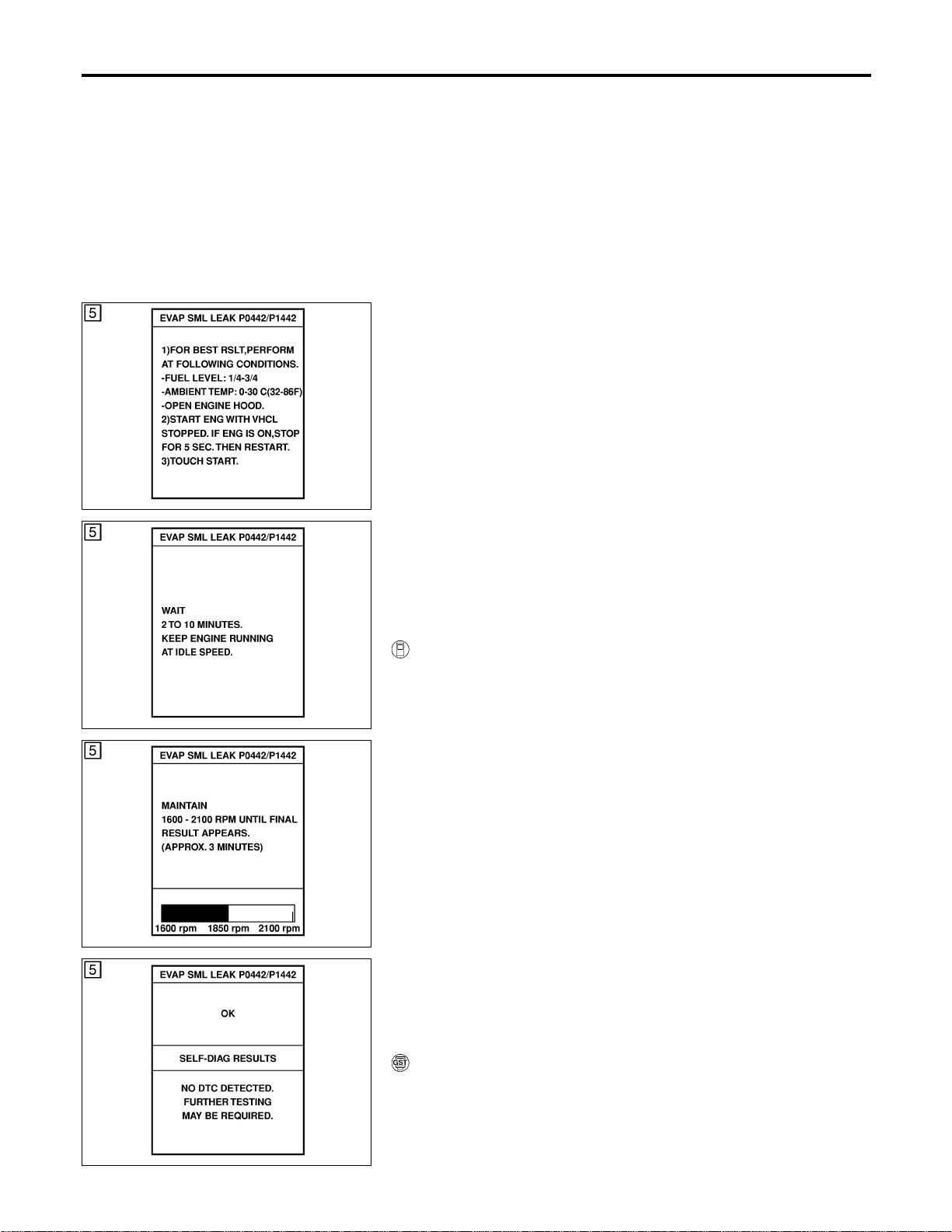
CAUTION:
I Use only a genuine NISSAN fuel filler cap as a replace-
ment. If an incorrect fuel filler cap is used, the MIL may
come on.
I If the fuel filler cap is not tightened properly, the MIL may
come on.
I Use only a genuine NISSAN rubber tube as a replacement.
SEC760C
SEC761C
SEC762C
SEC763C
DTC Confirmation Procedure
NFEC1444
NOTE:
I If DTC P0442 is displayed with P1448, perform trouble
diagnosis for DTC P1448 first (see EC-594).
I If “DTC Confirmation Procedure” has been previously
conducted, always turn ignition switch “OFF” and wait at least
10 seconds before conducting the next test.
I Make sure that EVAP hoses are connected to EVAP canis-
ter purge volume control solenoid valve properly.
TESTING CONDITION:
I Perform “DTC WORK SUPPORT” when the fuel level is
between 1/4 to 3/4 full and vehicle is placed on flat level
surface.
I Always perform test at a temperature of 0 to 30°C (32 to
86°F).
I Open engine hood before conducting the following proce-
dure.
WITH CONSULT-II
NFEC1444S01
1) Turn ignition switch “ON”.
2) Turn ignition switch “OFF” and wait at least 10 seconds.
3) Turn ignition switch “ON” and select “DATA MONITOR” mode
with CONSULT-II.
4) Make sure that the following conditions are met.
COOLAN TEMP/S: 0 - 70°C (32 - 158°F)
INT/A TEMP SE: 0 - 30°C (32 - 86°F)
5) Select “EVP SML LEAK P0442/P1442” of “EVAPORATIVE
SYSTEM” in “DTC WORK SUPPORT” mode with CONSULT-
II.
Follow the instruction displayed.
NOTE:
If the engine speed cannot be maintained within the range dis-
played on the CONSULT-II screen, go to “Basic Inspection”,
EC-123.
6) Make sure that “OK” is displayed.
If “NG” is displayed, refer to “Diagnostic Procedure”, EC-363.
NOTE:
Make sure that EVAP hoses are connected to EVAP canister
purge volume control solenoid valve properly.
WITH GST
NFEC1444S02
NOTE:
Be sure to read the explanation of “Driving Pattern” on EC-83
before driving vehicle.
1) Start engine.
2) Drive vehicle according to “Driving Pattern”, EC-83.
DTC P0442 EVAP CONTROL SYSTEM
On Board Diagnosis Logic (Cont’d)
EC-362

3) Stop vehicle.
4) Select “MODE 1” with GST.
I If SRT of EVAP system is not set yet, go to the following step.
I If SRT of EVAP system is set, the result will be OK.
5) Turn ignition switch “OFF” and wait at least 10 seconds.
6) Start engine.
It is not necessary to cool engine down before driving.
7) Drive vehicle again according to the “Driving Pattern”, EC-83.
8) Stop vehicle.
9) Select “MODE 3” with GST.
I If P0442 is displayed on the screen, go to “Diagnostic
Procedure”, EC-363.
I If P0441 is displayed on the screen, go to “Diagnostic Proce-
dure” for DTC P0441, EC-354.
I If P0441 and P0442 are not displayed on the screen, go to the
following step.
10) Select “MODE 1” with GST.
I If SRT of EVAP system is set, the result will be OK.
I If SRT of EVAP system is not set, go to step 6.
Diagnostic Procedure
NFEC0962
1 CHECK FUEL FILLER CAP DESIGN
1. Turn ignition switch “OFF”.
2. Check for genuine NISSAN fuel filler cap design.
SEF915U
OK or NG
OK © GO TO 2.
NG © Replace with genuine NISSAN fuel filler cap.
2 CHECK FUEL FILLER CAP INSTALLATION
Check that the cap is tightened properly by rotating the cap clockwise.
OK or NG
OK © GO TO 3.
NG © I Open fuel filler cap, then clean cap and fuel filler neck threads using air blower.
I Retighten until ratcheting sound is heard.
GI
MA
EM
LC
FE
CL
MT
AT
AX
SU
BR
ST
RS
BT
HA
SC
EL
IDX
DTC P0442 EVAP CONTROL SYSTEM
DTC Confirmation Procedure (Cont’d)
EC-363
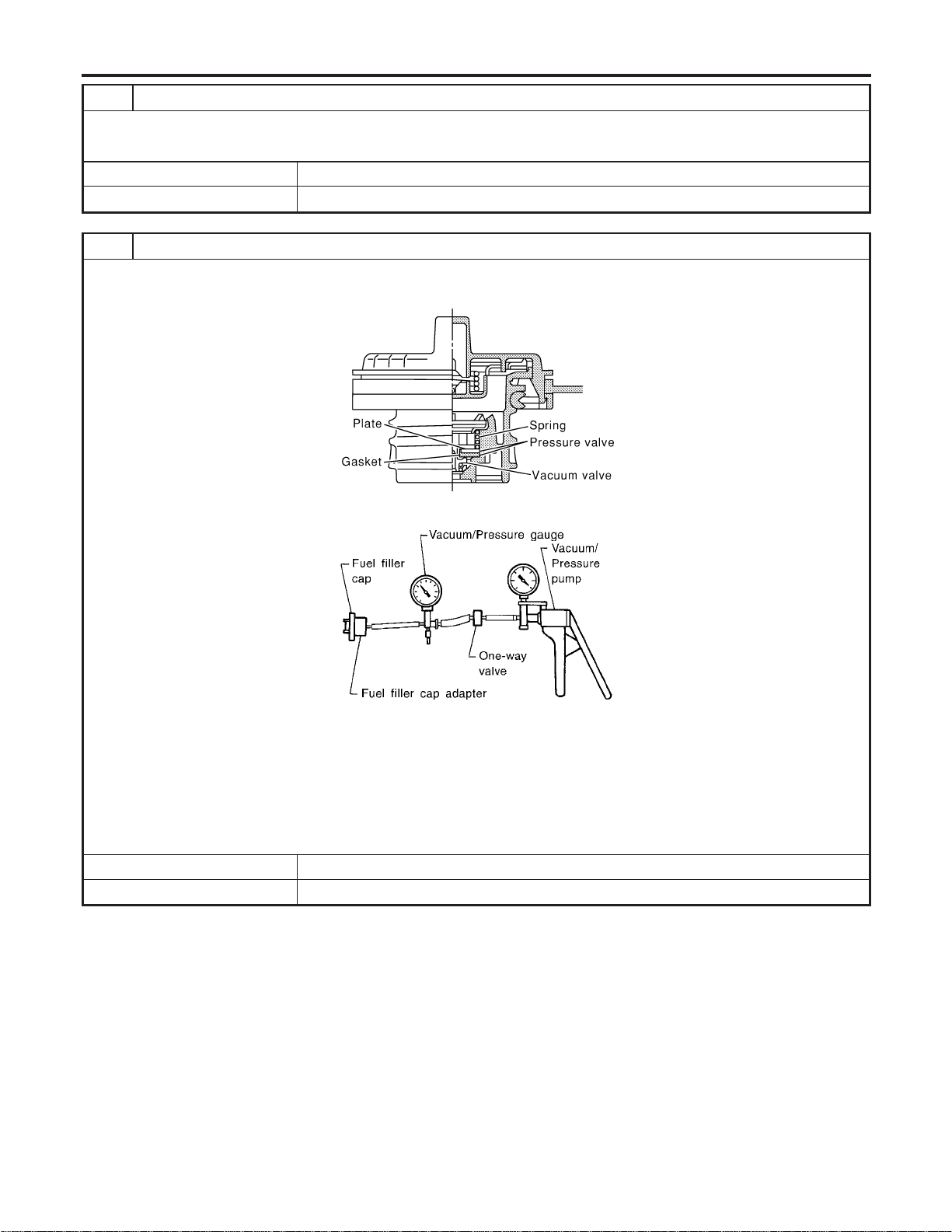
3 CHECK FUEL FILLER CAP FUNCTION
Check for air releasing sound while opening the fuel filler cap.
OK or NG
OK © GO TO 5.
NG © GO TO 4.
4 CHECK FUEL TANK VACUUM RELIEF VALVE
1. Wipe clean valve housing.
2. Check valve opening pressure and vacuum.
SEF445Y
SEF943S
Pressure:
15.3 - 20.0 kPa (0.156 - 0.204 kg/cm
2
, 2.22 - 2.90 psi)
Vacuum:
−6.0 to −3.3 kPa (−0.061 to −0.034 kg/cm
2
, −0.87 to −0.48 psi)
CAUTION:
Use only a genuine fuel filler cap as a replacement. If an incorrect fuel filler cap is used, the MIL may come on.
OK or NG
OK © GO TO 5.
NG © Replace fuel filler cap with a genuine one.
DTC P0442 EVAP CONTROL SYSTEM
Diagnostic Procedure (Cont’d)
EC-364
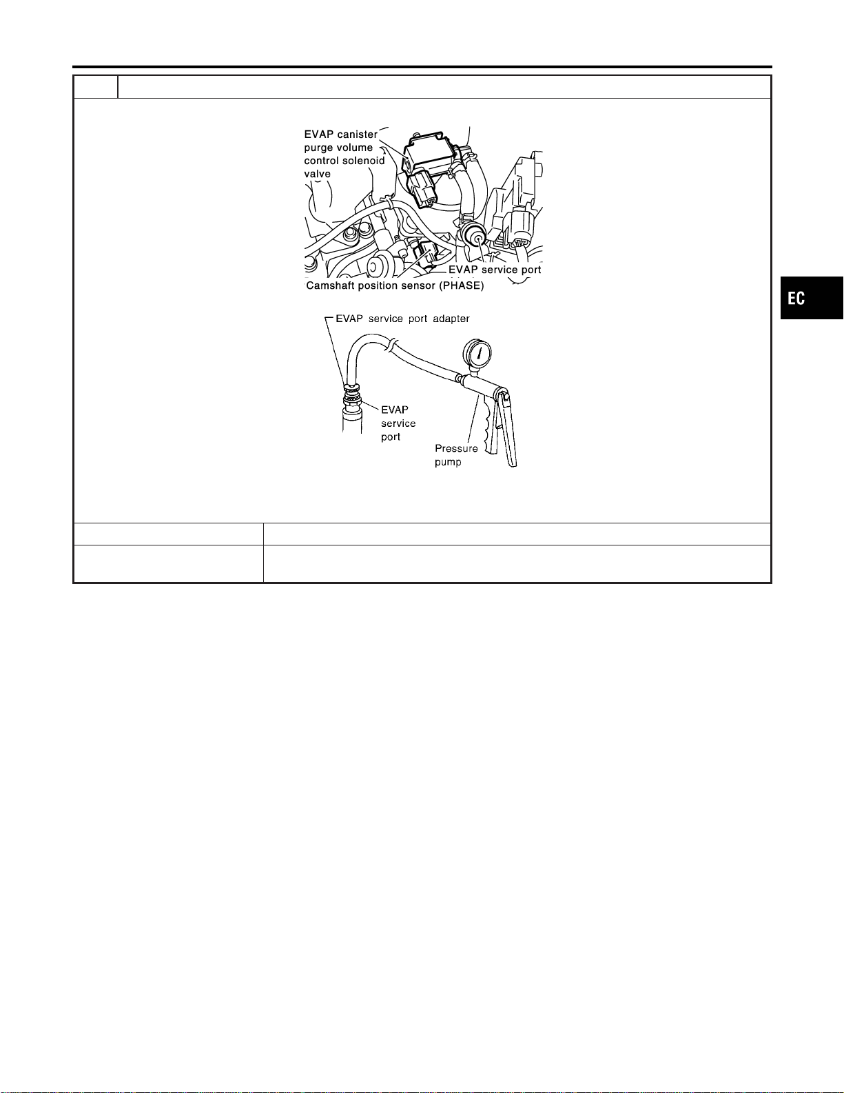
5 INSTALL THE PRESSURE PUMP
To locate the EVAP leak, install EVAP service port adapter and pressure pump to EVAP service port securely.
SEC929C
SEF916U
NOTE:
Improper installation of the EVAP service port adapter to the EVAP service port may cause leaking.
Models with CONSULT-II © GO TO 6.
Models without CON-
SULT-II
© GO TO 7.
GI
MA
EM
LC
FE
CL
MT
AT
AX
SU
BR
ST
RS
BT
HA
SC
EL
IDX
DTC P0442 EVAP CONTROL SYSTEM
Diagnostic Procedure (Cont’d)
EC-365
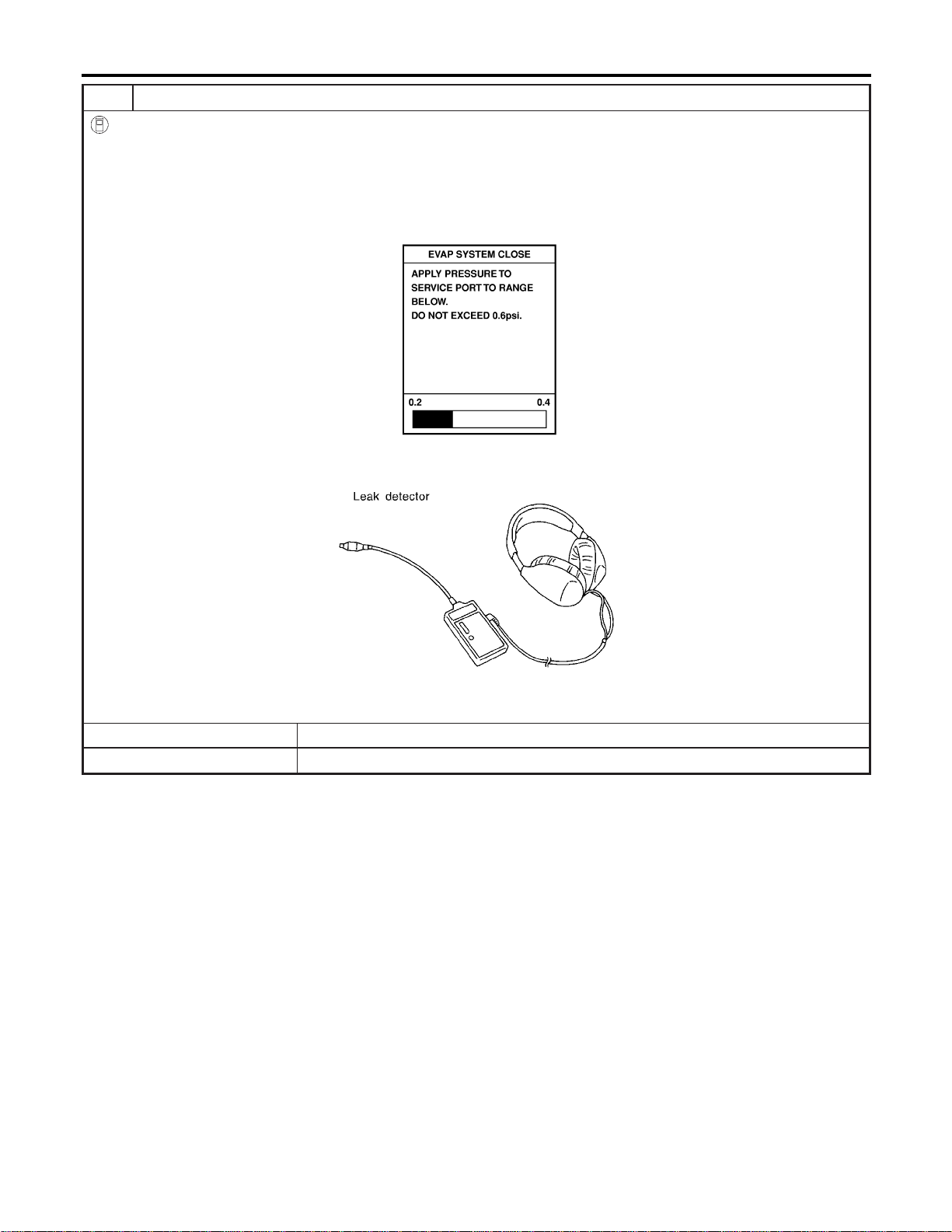
6 CHECK FOR EVAP LEAK
With CONSULT-II
1. Turn ignition switch “ON”.
2. Select “EVAP SYSTEM CLOSE” of “WORK SUPPORT” mode with CONSULT-II.
3. Touch “START” and apply pressure into the EVAP line until the pressure indicator reaches the middle of the bar graph.
NOTE:
I Never use compressed air or a high pressure pump.
I Do not exceed 4.12 kPa (0.042 kg/cm
2
, 0.6 psi) of pressure in the system.
PEF917U
4. Using EVAP leak detector, locate the EVAP leak. For the leak detector, refer to the instruction manual for more details.
Refer to “EVAPORATIVE EMISSION LINE DRAWING”, EC-40.
SEF200U
OK or NG
OK © GO TO 8.
NG © Repair or replace.
DTC P0442 EVAP CONTROL SYSTEM
Diagnostic Procedure (Cont’d)
EC-366
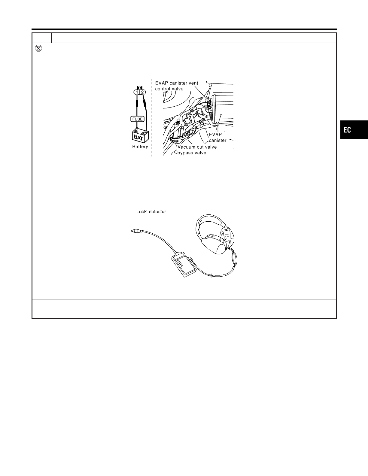
7 CHECK FOR EVAP LEAK
Without CONSULT-II
1. Turn ignition switch “OFF”.
2. Apply 12 volts DC to EVAP canister vent control valve. The valve will close. (Continue to apply 12 volts until the end of
test.)
3. Apply 12 volts DC to vacuum cut valve bypass valve. The valve will open. (Continue to apply 12V until the end of test.)
SEF254X
4. Pressurize the EVAP line using pressure pump with 1.3 to 2.7 kPa (10 to 20 mmHg, 0.39 to 0.79 inHg), then remove
pump and EVAP service port adapter.
NOTE:
I Never use compressed air or a high pressure pump.
I Do not exceed 4.12 kPa (0.042 kg/cm
2
, 0.6 psi) of pressure in the system.
5. Using EVAP leak detector, locate the EVAP leak. For the leak detector, refer to the instruction manual for more details.
Refer to “EVAPORATIVE EMISSION LINE DRAWING”, EC-40.
SEF200U
OK or NG
OK © GO TO 8.
NG © Repair or replace.
GI
MA
EM
LC
FE
CL
MT
AT
AX
SU
BR
ST
RS
BT
HA
SC
EL
IDX
DTC P0442 EVAP CONTROL SYSTEM
Diagnostic Procedure (Cont’d)
EC-367
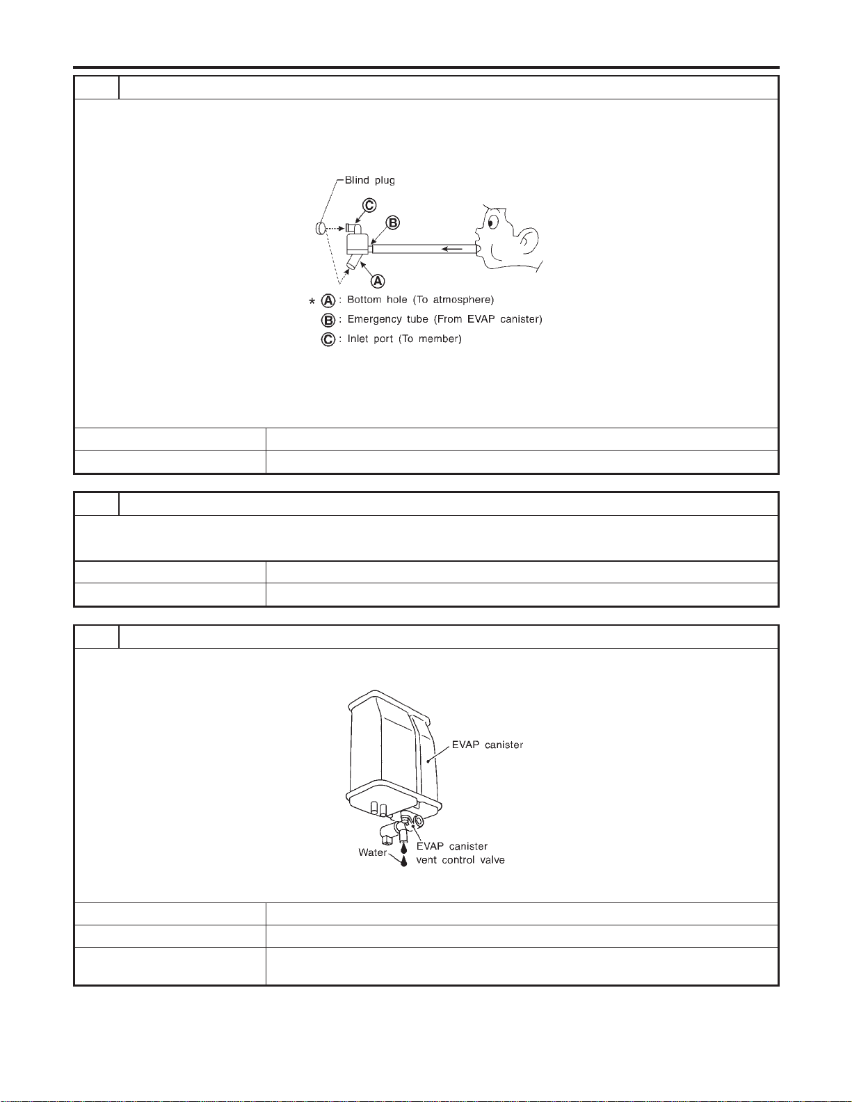
8 CHECK WATER SEPARATOR
1. Check visually for insect nests in the water separator air inlet.
2. Check visually for cracks or flaws in the appearance.
3. Check visually for cracks or flaws in the hose.
4. Check that A and C are not clogged by blowing air into B with A, and then C plugged.
SEF829T
5. In case of NG in items2-4,replace the parts.
NOTE:
I Do not disassemble water separator.
OK or NG
OK © GO TO 9.
NG © Replace water separator.
9 CHECK EVAP CANISTER VENT CONTROL VALVE, O-RING AND CIRCUIT
Refer to “DTC Confirmation Procedure”, EC-594.
OK or NG
OK © GO TO 10.
NG © Repair or replace EVAP canister vent control valve and O-ring or harness/connector.
10 CHECK IF EVAP CANISTER SATURATED WITH WATER
1. Remove EVAP canister with EVAP canister vent control valve attached.
2. Does water drain from the EVAP canister?
SEF596U
YesorNo
Yes © GO TO 11.
No (With CONSULT-II) © GO TO 13.
No (Without CONSULT-
II)
© GO TO 14.
DTC P0442 EVAP CONTROL SYSTEM
Diagnostic Procedure (Cont’d)
EC-368
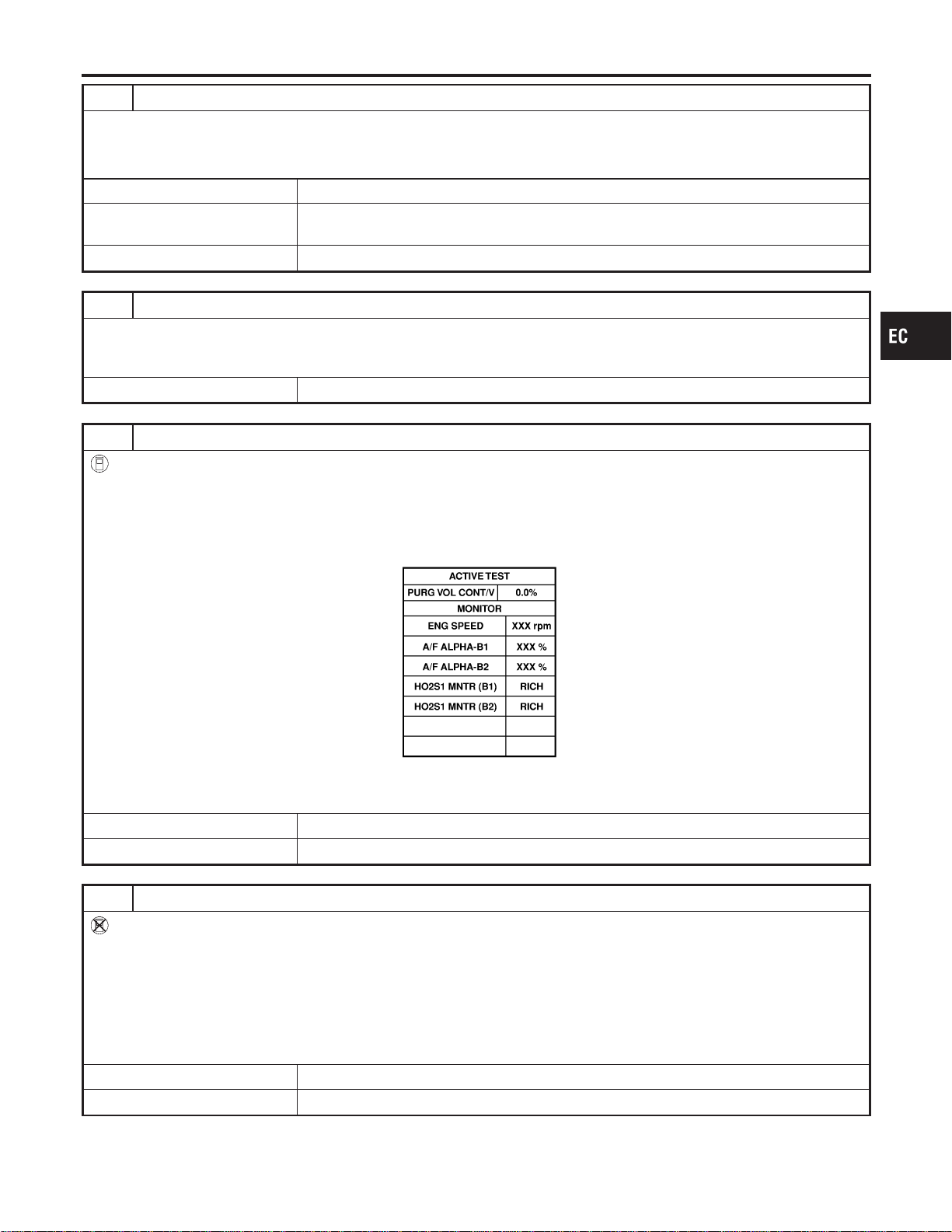
11 CHECK EVAP CANISTER
Weigh the EVAP canister with the EVAP canister vent control valve attached.
The weight should be less than 1.8 kg (4.0 lb).
OK or NG
OK (With CONSULT-II) © GO TO 13.
OK (Without CONSULT-
II)
© GO TO 14.
NG © GO TO 12.
12 DETECT MALFUNCTIONING PART
Check the following.
I EVAP canister for damage
I EVAP hose between EVAP canister and water separator for clogging or poor connection
© Repair hose or replace EVAP canister.
13 CHECK EVAP CANISTER PURGE VOLUME CONTROL SOLENOID VALVE OPERATION
With CONSULT-II
1. Disconnect vacuum hose to EVAP canister purge volume control solenoid valve at EVAP service port.
2. Start engine.
3. Perform “PURG VOL CONT/V” in “ACTIVE TEST” mode.
4. Touch “Qu” on CONSULT-II screen to increase “PURG VOL CONT/V” opening to 100.0%.
5. Check vacuum hose for vacuum when revving engine up to 2,000 rpm.
SEC142D
Vacuum should exist.
OK or NG
OK © GO TO 16.
NG © GO TO 15.
14 CHECK EVAP CANISTER PURGE VOLUME CONTROL SOLENOID VALVE OPERATION
Without CONSULT-II
1. Start engine and warm it up to normal operating temperature.
2. Stop engine.
3. Disconnect vacuum hose to EVAP canister purge volume control solenoid valve at EVAP service port.
4. Start engine and let it idle for at least 80 seconds.
5. Check vacuum hose for vacuum when revving engine up to 2,000 rpm.
Vacuum should exist.
OK or NG
OK © GO TO 17.
NG © GO TO 15.
GI
MA
EM
LC
FE
CL
MT
AT
AX
SU
BR
ST
RS
BT
HA
SC
EL
IDX
DTC P0442 EVAP CONTROL SYSTEM
Diagnostic Procedure (Cont’d)
EC-369
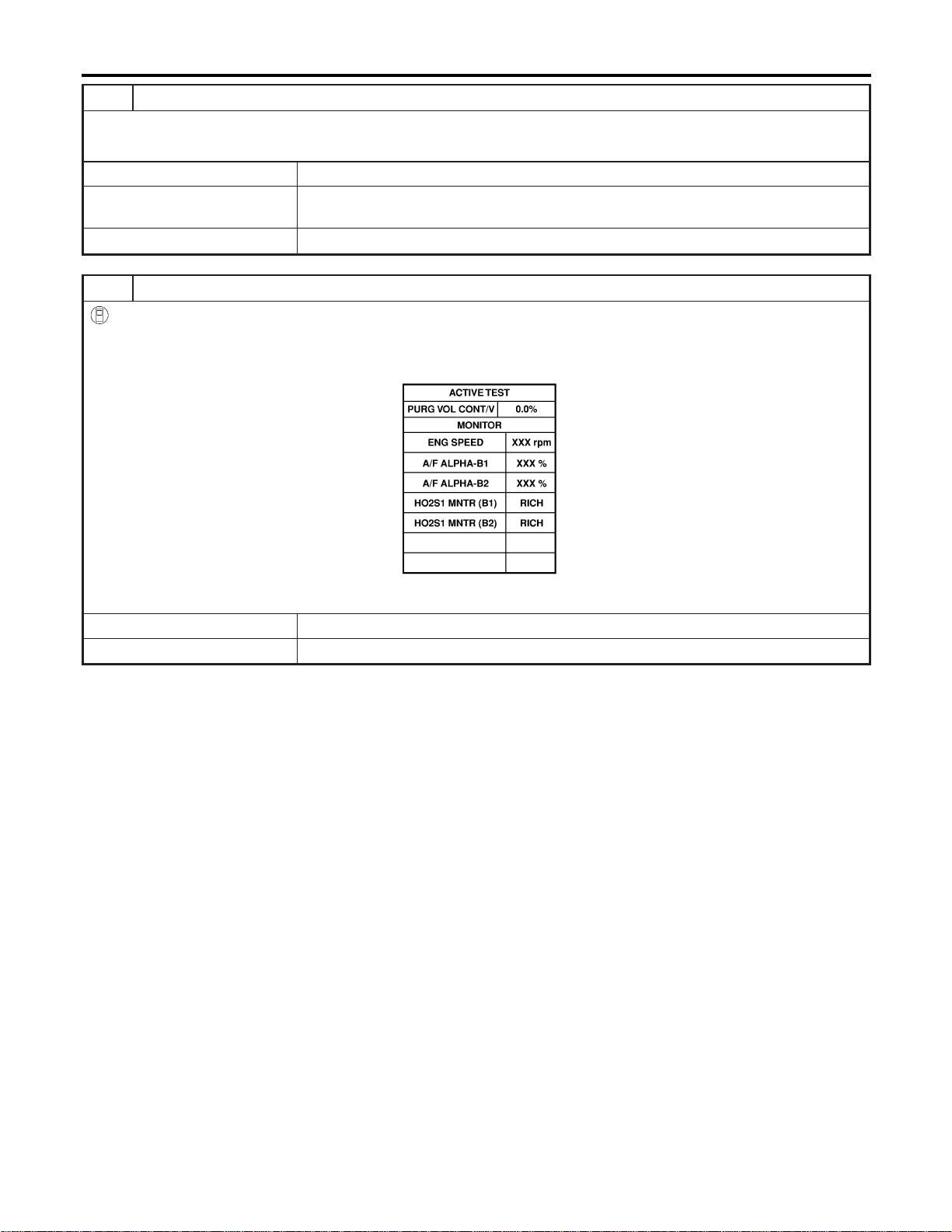
15 CHECK VACUUM HOSE
Check vacuum hoses for clogging or disconnection. Refer to “Vacuum Hose Drawing”, EC-30.
OK or NG
OK (With CONSULT-II) © GO TO 16.
OK (Without CONSULT-
II)
© GO TO 17.
NG © Repair or reconnect the hose.
16 CHECK EVAP CANISTER PURGE VOLUME CONTROL SOLENOID VALVE
With CONSULT-II
1. Start engine.
2. Perform “PURG VOL CONT/V” in “ACTIVE TEST” mode with CONSULT-II. Check that engine speed varies according
to the valve opening.
SEC142D
OK or NG
OK © GO TO 18.
NG © GO TO 17.
DTC P0442 EVAP CONTROL SYSTEM
Diagnostic Procedure (Cont’d)
EC-370
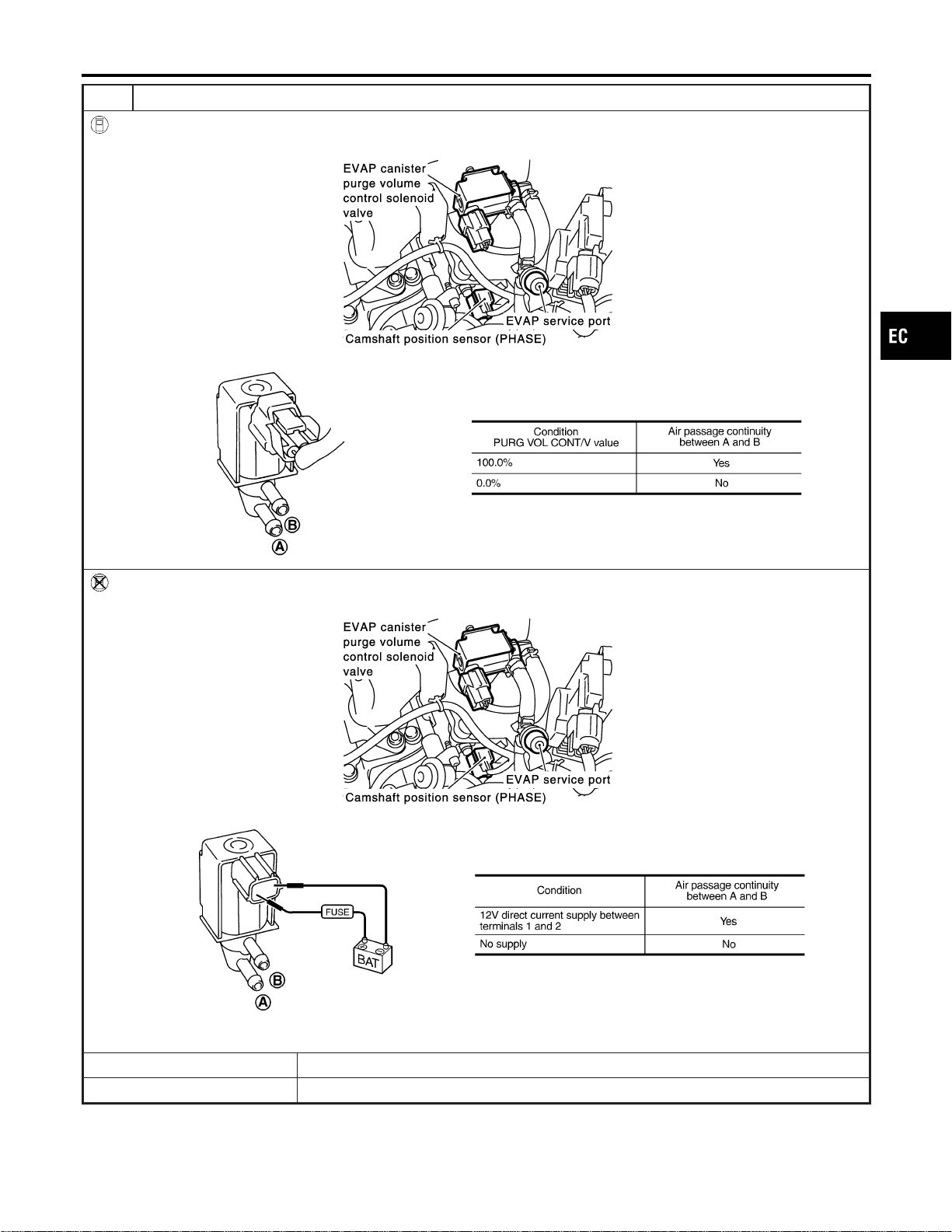
17 CHECK EVAP CANISTER PURGE VOLUME CONTROL SOLENOID VALVE
With CONSULT-II
Check air passage continuity of EVAP canister purge volume control solenoid valve under the following conditions.
SEC929C
SEF334X
Without CONSULT-II
Check air passage continuity of EVAP canister purge volume control solenoid valve under the following conditions.
SEC929C
SEF335X
OK or NG
OK © GO TO 18.
NG © Replace EVAP canister purge volume control solenoid valve.
GI
MA
EM
LC
FE
CL
MT
AT
AX
SU
BR
ST
RS
BT
HA
SC
EL
IDX
DTC P0442 EVAP CONTROL SYSTEM
Diagnostic Procedure (Cont’d)
EC-371
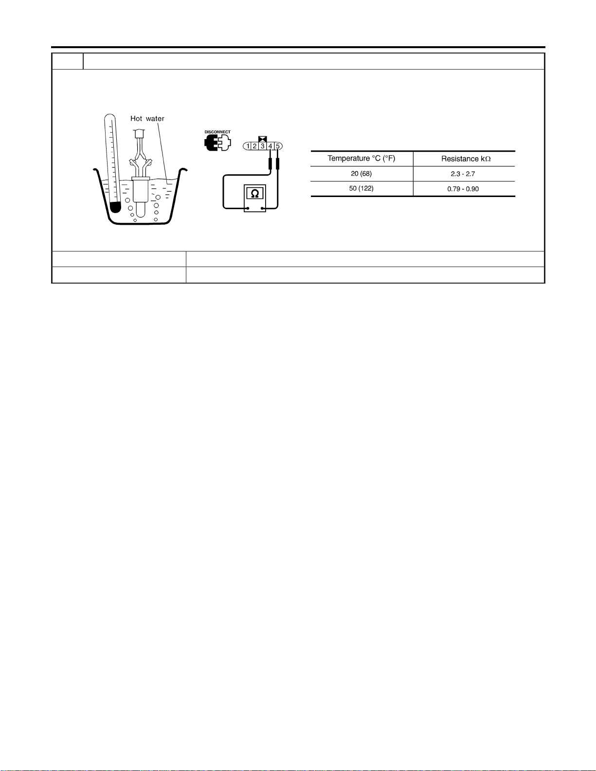
18 CHECK FUEL TANK TEMPERATURE SENSOR
1. Remove fuel level sensor unit.
2. Check resistance between fuel level sensor unit and fuel pump terminals 4 and 5 by heating with hot water or heat gun
as shown in the figure.
SEF587X
OK or NG
OK © GO TO 19.
NG © Replace fuel level sensor unit.
DTC P0442 EVAP CONTROL SYSTEM
Diagnostic Procedure (Cont’d)
EC-372
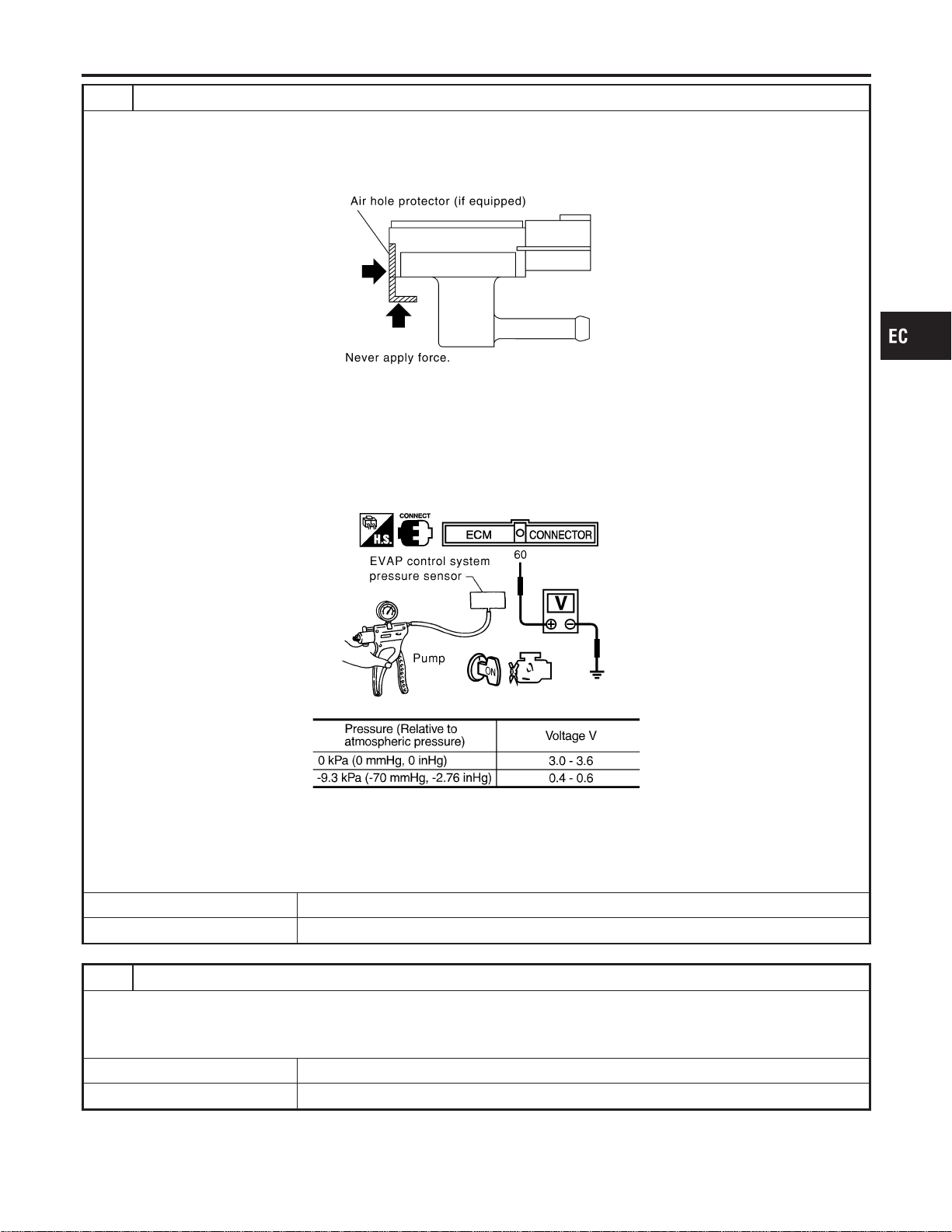
19 CHECK EVAP CONTROL SYSTEM PRESSURE SENSOR
1. Remove EVAP control system pressure sensor with its harness connector connected.
CAUTION:
Never apply force to the air hole protector of the sensor if equipped.
SEF799W
2. Remove hose from EVAP control system pressure sensor.
3. Turn ignition switch “ON”.
4. Use pump to apply vacuum and pressure to EVAP control system pressure sensor as shown in figure.
CAUTION:
I Always calibrate the vacuum pump gauge when using it.
I Do not apply below −20 kPa (−150 mmHg, −5.91 inHg) or over 20 kPa (150 mmHg, 5.91 inHg) of pressure.
5. Check input voltage between ECM terminal 60 and ground.
SEC908C
MTBL1159
CAUTION:
Discard and EVAP control system pressure sensor which has been dropped from a height of more than 0.5 m
(19.7 in) onto a hard surface such as a concrete floor; use a new one.
OK or NG
OK © GO TO 20.
NG © Replace EVAP control system pressure sensor.
20 CHECK EVAP PURGE LINE
Check EVAP purge line (pipe, rubber tube, fuel tank and EVAP canister) for cracks or improper connection.
Refer to “Evaporative Emission System”, EC-36.
OK or NG
OK © GO TO 21.
NG © Repair or reconnect the hose.
GI
MA
EM
LC
FE
CL
MT
AT
AX
SU
BR
ST
RS
BT
HA
SC
EL
IDX
DTC P0442 EVAP CONTROL SYSTEM
Diagnostic Procedure (Cont’d)
EC-373
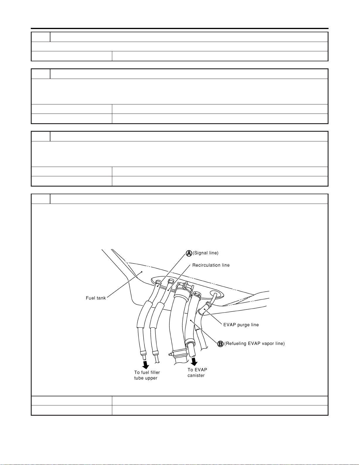
21 CLEAN EVAP PURGE LINE
Clean EVAP purge line (pipe and rubber tube) using air blower.
© GO TO 22.
22 CHECK REFUELING EVAP VAPOR LINE
Check refueling EVAP vapor line between EVAP canister and fuel tank for clogging, kink, looseness and improper connec-
tion. For location, refer to “ON BOARD REFUELING VAPOR RECOVERY (ORVR)”, EC-42.
OK or NG
OK © GO TO 23.
NG © Repair or replace hoses and tubes.
23 CHECK SIGNAL LINE AND RECIRCULATION LINE
Check signal line and recirculation line between filler neck tube and fuel tank for clogging, kink, cracks, looseness and
improper connection.
OK or NG
OK © GO TO 24.
NG © Repair or replace hoses, tubes or filler neck tube.
24 CHECK REFUELING CONTROL VALVE
1. Remove fuel filler cap.
2. Check air continuity between hose ends A and B.
Blow air into the hose end B. Air should flow freely into the fuel tank.
3. Blow air into hose end A and check there is no leakage.
4. Apply pressure to both hose ends A and B [20 kPa (150 mmHg, 5.91 inHg)] using a pressure pump and a suitable
3-way connector. Check that there is no leakage.
SEF830X
OK or NG
OK © GO TO 25.
NG © Replace refueling control valve with fuel tank.
DTC P0442 EVAP CONTROL SYSTEM
Diagnostic Procedure (Cont’d)
EC-374
25 CHECK FUEL LEVEL SENSOR
Refer to EL-129, “Fuel Level Sensor Unit Check”.
OK or NG
OK © GO TO 26.
NG © Replace fuel level sensor unit.
26 CHECK INTERMITTENT INCIDENT
Refer to “TROUBLE DIAGNOSIS FOR INTERMITTENT INCIDENT”, EC-156.
© INSPECTION END
GI
MA
EM
LC
FE
CL
MT
AT
AX
SU
BR
ST
RS
BT
HA
SC
EL
IDX
DTC P0442 EVAP CONTROL SYSTEM
Diagnostic Procedure (Cont’d)
EC-375
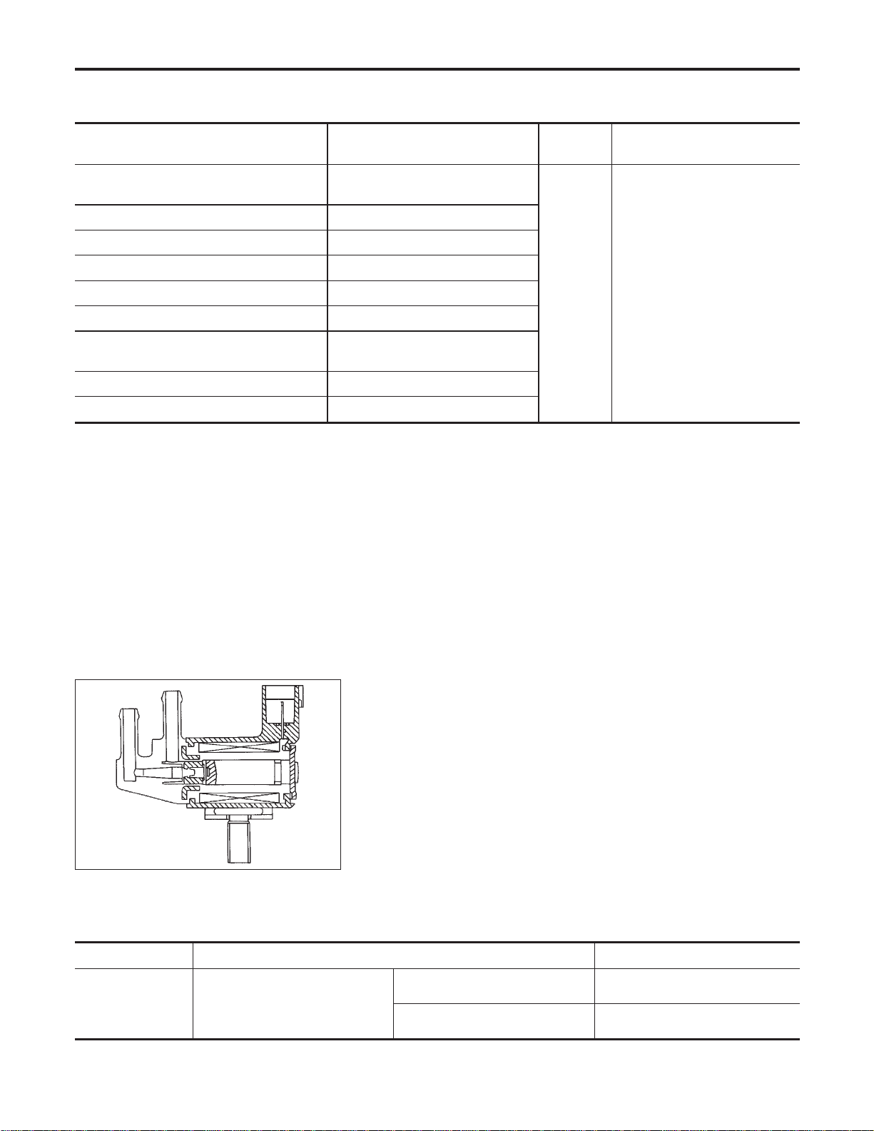
Description
NFEC0963
SYSTEM DESCRIPTION
NFEC0963S01
Sensor Input Signal to ECM
ECM
function
Actuator
Crankshaft position sensor (POS)
Camshaft position sensor (PHASE)
Engine speed
EVAP can-
ister purge
flow control
EVAP canister purge volume
control solenoid valve
Mass air flow sensor Amount of intake air
Engine coolant temperature sensor Engine coolant temperature
Ignition switch Start signal
Throttle position sensor Throttle position
Accelerator pedal position sensor Accelerator pedal position
Heated oxygen sensor 1
Density of oxygen in exhaust gas
(Mixture ratio feedback signal)
Fuel tank temperature sensor Fuel temperature in fuel tank
Vehicle speed sensor Vehicle speed
This system controls flow rate of fuel vapor from the EVAP canis-
ter. The opening of the vapor by-pass passage in the EVAP canis-
ter purge volume control solenoid valve changes to control the flow
rate. The EVAP canister purge volume control solenoid valve
repeats ON/OFF operation according to the signal sent from the
ECM. The opening of the valve varies for optimum engine control.
The optimum value stored in the ECM is determined by consider-
ing various engine conditions. When the engine is operating, the
flow rate of fuel vapor from the EVAP canister is regulated as the
air flow changes.
SEF337U
COMPONENT DESCRIPTION
NFEC0963S02
The EVAP canister purge volume control solenoid valve uses a
ON/OFF duty to control the flow rate of fuel vapor from the EVAP
canister. The EVAP canister purge volume control solenoid valve
is moved by ON/OFF pulses from the ECM. The longer the ON
pulse, the greater the amount of fuel vapor that will flow through the
valve.
CONSULT-II Reference Value in Data Monitor
Mode
NFEC0964
Specification data are reference values.
MONITOR ITEM CONDITION SPECIFICATION
PURG VOL C/V
I Engine: After warming up
I Air conditioner switch “OFF”
I Shift lever: “N”
I No-load
Idle (Vehicle stopped) 0%
2,000 rpm —
DTC P0444, P0445 EVAP CANISTER PURGE VOLUME CONTROL SOLENOID
VALVE
Description
EC-376
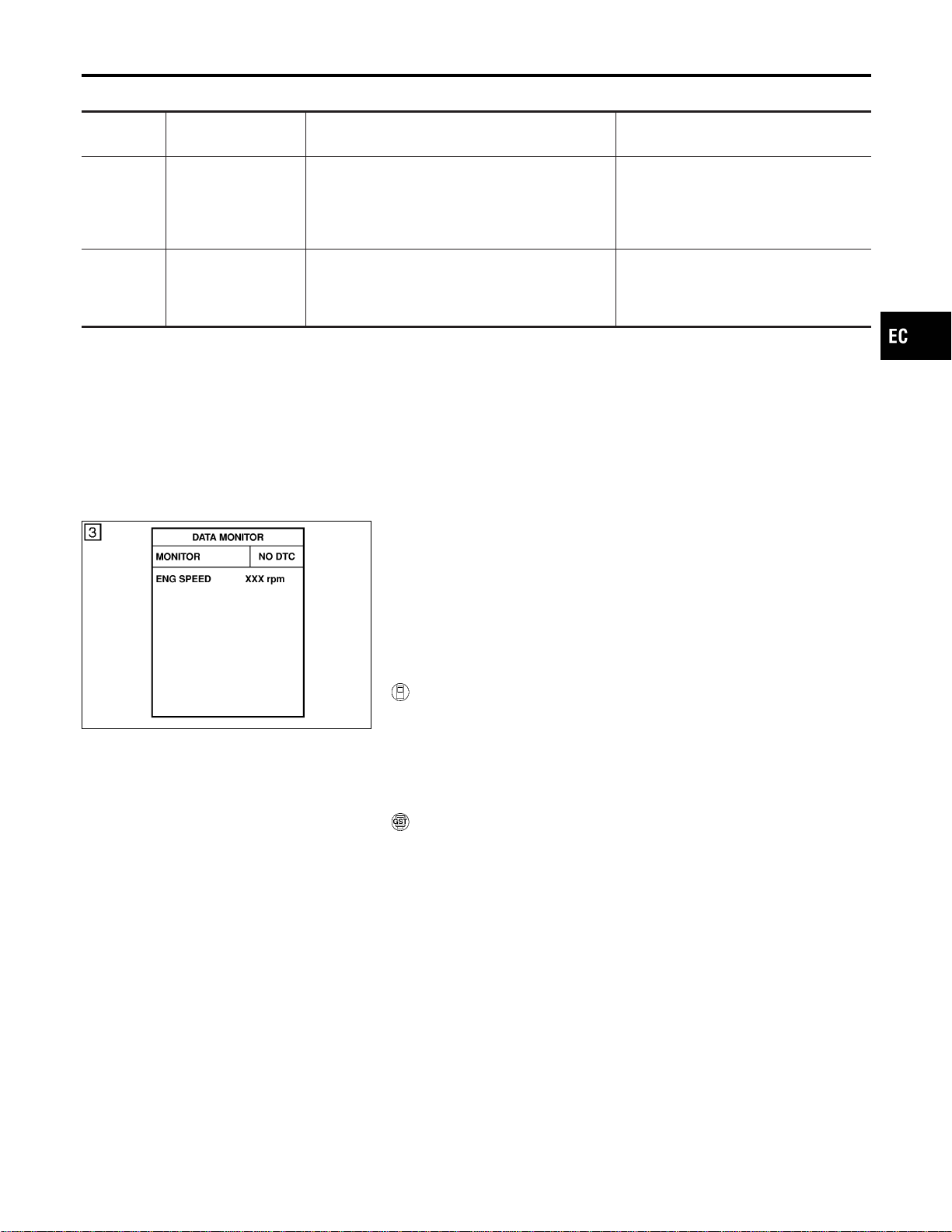
On Board Diagnosis Logic
NFEC0966
DTC No.
Trouble diagnosis
name
DTC Detecting Condition Possible Cause
P0444
0444
EVAP canister purge
volume control sole-
noid valve circuit
open
An excessively low voltage signal is sent to ECM
through the valve.
I Harness or connectors
(The solenoid valve circuit is open or
shorted.)
I EVAP canister purge volume control
solenoid valve
P0445
0445
EVAP canister purge
volume control sole-
noid valve circuit
shorted
An excessively high voltage signal is sent to ECM
through the valve.
I Harness or connectors
(The solenoid valve circuit is shorted.)
I EVAP canister purge volume control
solenoid valve
SEF058Y
DTC Confirmation Procedure
NFEC0967
NOTE:
If “DTC Confirmation Procedure” has been previously conducted,
always turn ignition switch “OFF” and wait at least 10 seconds
before conducting the next test.
TESTING CONDITION:
Before performing the following procedure, confirm battery
voltage is more than 11V at idle.
WITH CONSULT-II
NFEC0967S01
1) Turn ignition switch “ON”.
2) Select “DATA MONITOR” mode with CONSULT-II.
3) Start engine and let it idle for at least 13 seconds.
4) If 1st trip DTC is detected, go to “Diagnostic Procedure”,
EC-380.
WITH GST
NFEC0967S02
Follow the proocedure “WITH CONSULT-II” above.
GI
MA
EM
LC
FE
CL
MT
AT
AX
SU
BR
ST
RS
BT
HA
SC
EL
IDX
DTC P0444, P0445 EVAP CANISTER PURGE VOLUME CONTROL SOLENOID
VALVE
On Board Diagnosis Logic
EC-377
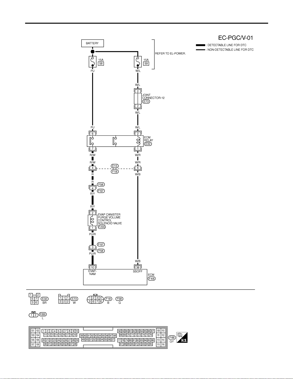
Wiring Diagram
NFEC0968
MEC494D
DTC P0444, P0445 EVAP CANISTER PURGE VOLUME CONTROL SOLENOID
VALVE
Wiring Diagram
EC-378
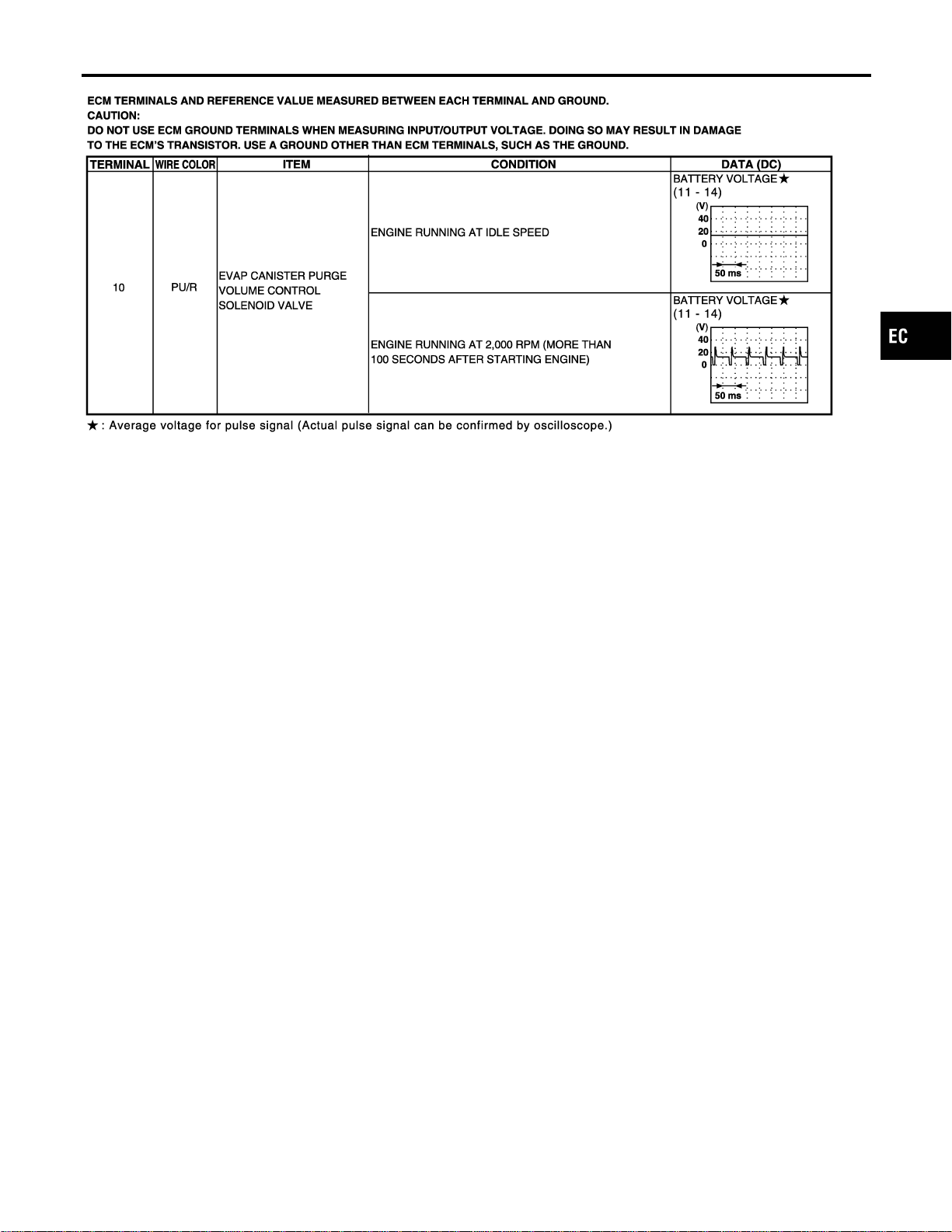
SEC219D
GI
MA
EM
LC
FE
CL
MT
AT
AX
SU
BR
ST
RS
BT
HA
SC
EL
IDX
DTC P0444, P0445 EVAP CANISTER PURGE VOLUME CONTROL SOLENOID
VALVE
Wiring Diagram (Cont’d)
EC-379
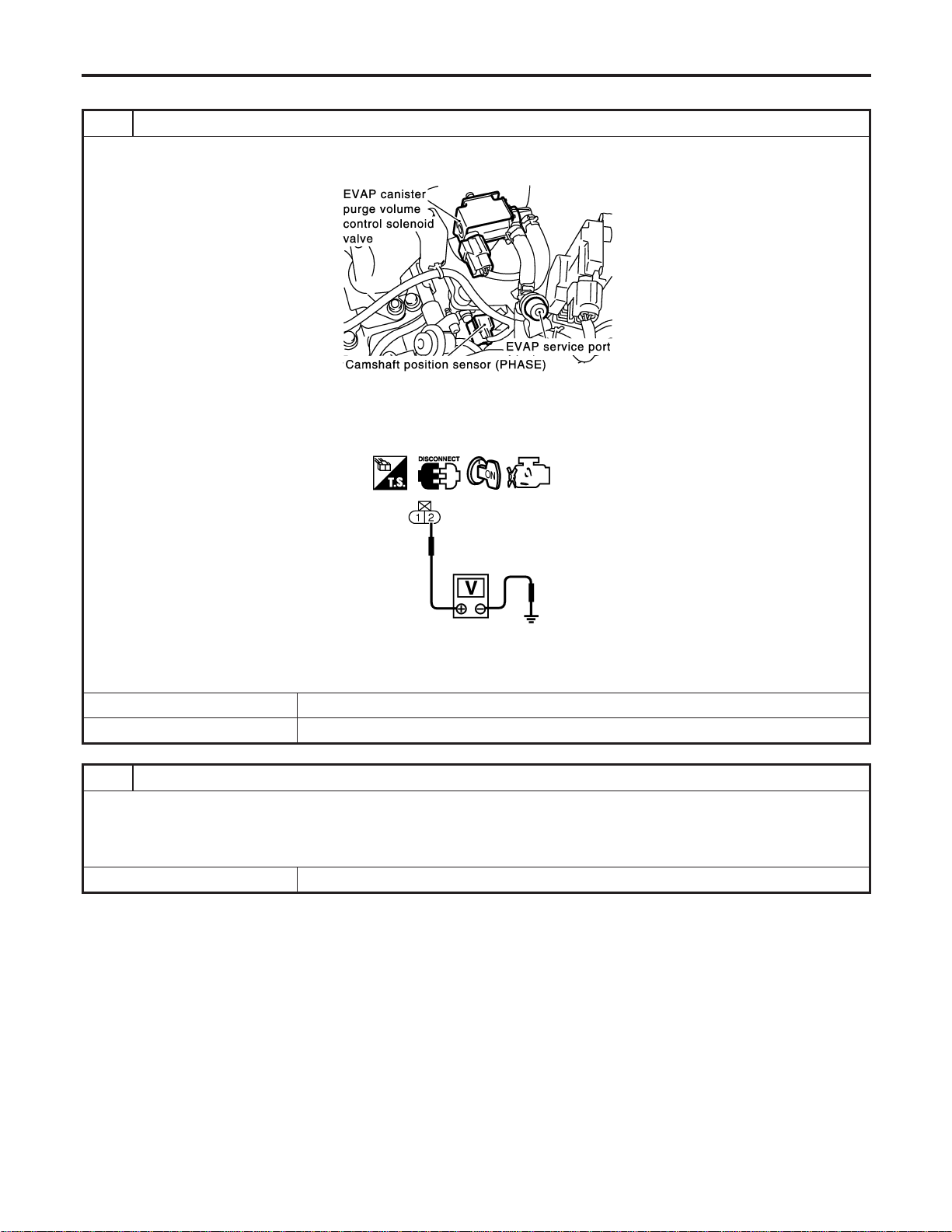
Diagnostic Procedure
NFEC0969
1 CHECK EVAP CANISTER PURGE VOLUME CONTROL SOLENOID VALVE POWER SUPPLY CIRCUIT
1. Turn ignition switch “OFF”.
2. Disconnect EVAP canister purge volume control solenoid valve harness connector.
SEC929C
3. Turn ignition switch “ON”.
4. Check voltage between EVAP canister purge volume control solenoid valve terminal 2 and ground with CONSULT-II or
tester.
SEC062D
Voltage: Battery voltage
OK or NG
OK © GO TO 3.
NG © GO TO 2.
2 DETECT MALFUNCTIONING PART
Check the following.
I Harness connectors E15, F18
I Harness connectors F58, F197
I Harness for open or short between EVAP canister purge volume control solenoid valve and ECM relay
© Repair harness or connectors.
DTC P0444, P0445 EVAP CANISTER PURGE VOLUME CONTROL SOLENOID
VALVE
Diagnostic Procedure
EC-380
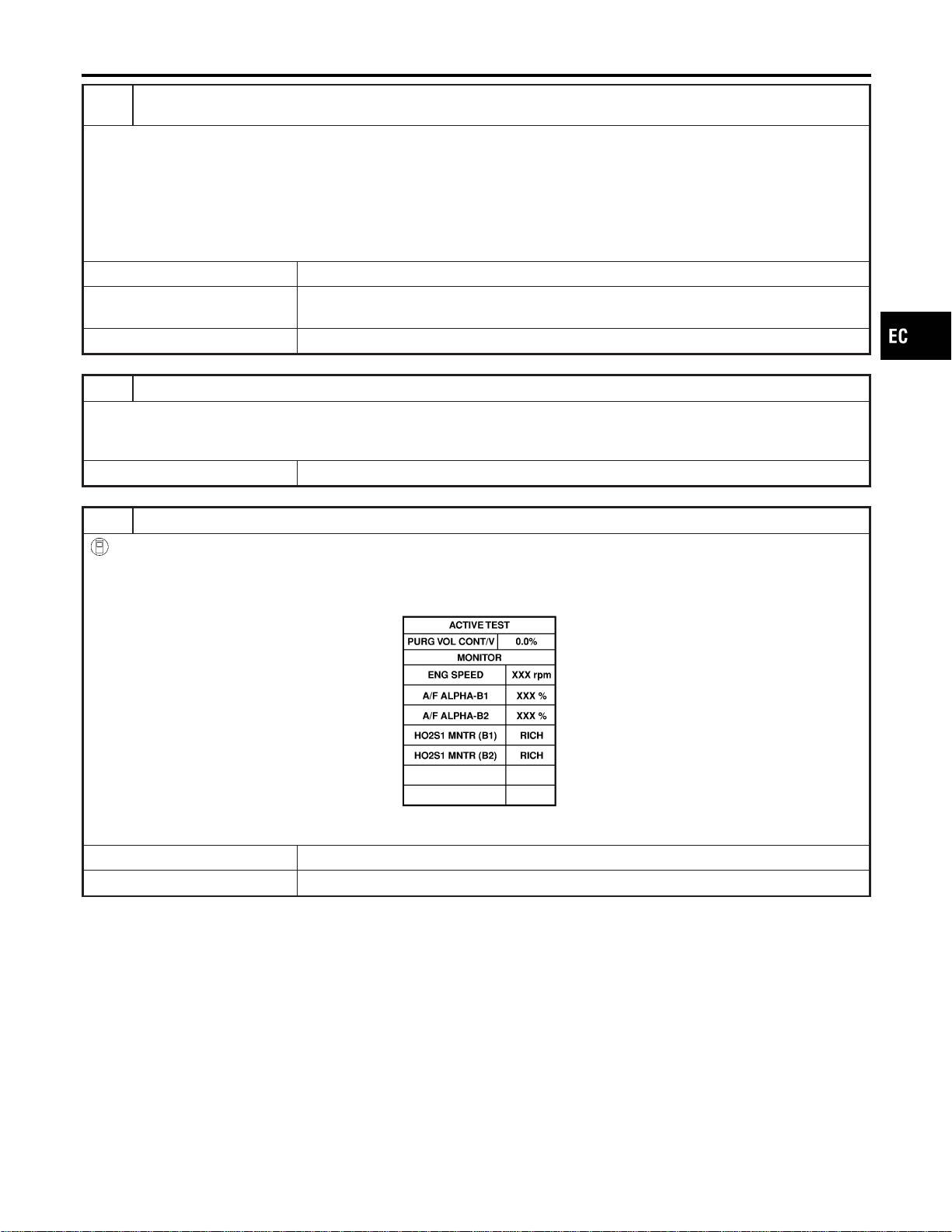
3 CHECK EVAP CANISTER PURGE VOLUME CONTROL SOLENOID VALVE OUTPUT SIGNAL CIRCUIT
FOR OPEN AND SHORT
1. Turn ignition switch “OFF”.
2. Disconnect ECM harness connector.
3. Check harness continuity between ECM terminal 10 and EVAP canister purge volume control solenoid valve terminal 1.
Refer to Wiring Diagram.
Continuity should exist.
4. Also check harness for short to ground and short to power.
OK or NG
OK (With CONSULT-II) © GO TO 5.
OK (Without CONSULT-
II)
© GO TO 6.
NG © GO TO 4.
4 DETECT MALFUNCTIONING PART
Check the following.
I Harness connectors F197, F58
I Harness for open or short between EVAP canister purge volume control solenoid valve and ECM
© Repair harness or connectors.
5 CHECK EVAP CANISTER PURGE VOLUME CONTROL SOLENOID VALVE OPERATION
With CONSULT-II
1. Start engine.
2. Perform “PURG VOL CONT/V” in “ACTIVE TEST” mode with CONSULT-II. Check that engine speed varies according
to the valve opening.
SEC142D
OK or NG
OK © GO TO 7.
NG © GO TO 6.
GI
MA
EM
LC
FE
CL
MT
AT
AX
SU
BR
ST
RS
BT
HA
SC
EL
IDX
DTC P0444, P0445 EVAP CANISTER PURGE VOLUME CONTROL SOLENOID
VALVE
Diagnostic Procedure (Cont’d)
EC-381
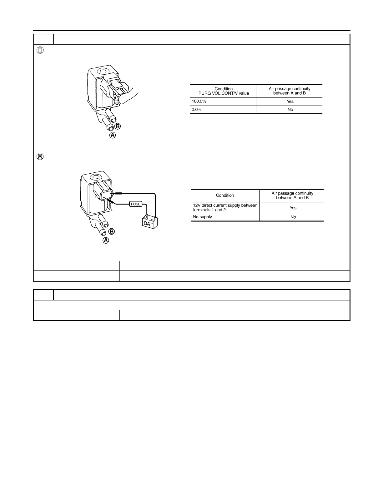
6 CHECK EVAP CANISTER PURGE VOLUME CONTROL SOLENOID VALVE
With CONSULT-II
Check air passage continuity of EVAP canister purge volume control solenoid valve under the following conditions.
SEF334X
Without CONSULT-II
Check air passage continuity of EVAP canister purge volume control solenoid valve under the following conditions.
SEF335X
OK or NG
OK © GO TO 7.
NG © Replace EVAP canister purge volume control solenoid valve.
7 CHECK INTERMITTENT INCIDENT
Refer to “TROUBLE DIAGNOSIS FOR INTERMITTENT INCIDENT”, EC-156.
© INSPECTION END
DTC P0444, P0445 EVAP CANISTER PURGE VOLUME CONTROL SOLENOID
VALVE
Diagnostic Procedure (Cont’d)
EC-382

SEF381Z
SEF267X
Component Description
NFEC0970
The EVAP canister vent control valve is located on the EVAP can-
ister and is used to seal the canister vent.
This solenoid valve responds to signals from the ECM. When the
ECM sends an ON signal, the coil in the solenoid valve is ener-
gized. A plunger will then move to seal the canister vent. The abil-
ity to seal the vent is necessary for the on board diagnosis of other
evaporative emission control system components.
This solenoid valve is used only for diagnosis, and usually remains
opened.
When the vent is closed, under normal purge conditions, the
evaporative emission control system is depressurized and allows
“EVAP Control System (Small Leak)” diagnosis.
CONSULT-II Reference Value in Data Monitor
Mode
NFEC0971
Specification data are reference values.
MONITOR ITEM CONDITION SPECIFICATION
VENT CONT/V I Ignition switch: ON OFF
On Board Diagnosis Logic
NFEC0973
DTC No.
Trouble diagnosis
name
DTC Detecting Condition Possible Cause
P0447
0447
EVAP canister vent
control valve circuit
open
An improper voltage signal is sent to ECM through
EVAP canister vent control valve.
I Harness or connectors
(The valve circuit is open or shorted.)
I EVAP canister vent control valve
DTC Confirmation Procedure
NFEC0974
NOTE:
If “DTC Confirmation Procedure” has been previously conducted,
always turn ignition switch “OFF” and wait at least 10 seconds
before conducting the next test.
TESTING CONDITION:
Before performing the following procedure, confirm battery
voltage is more than 11V at idle.
GI
MA
EM
LC
FE
CL
MT
AT
AX
SU
BR
ST
RS
BT
HA
SC
EL
IDX
DTC P0447 EVAP CANISTER VENT CONTROL VALVE
Component Description
EC-383
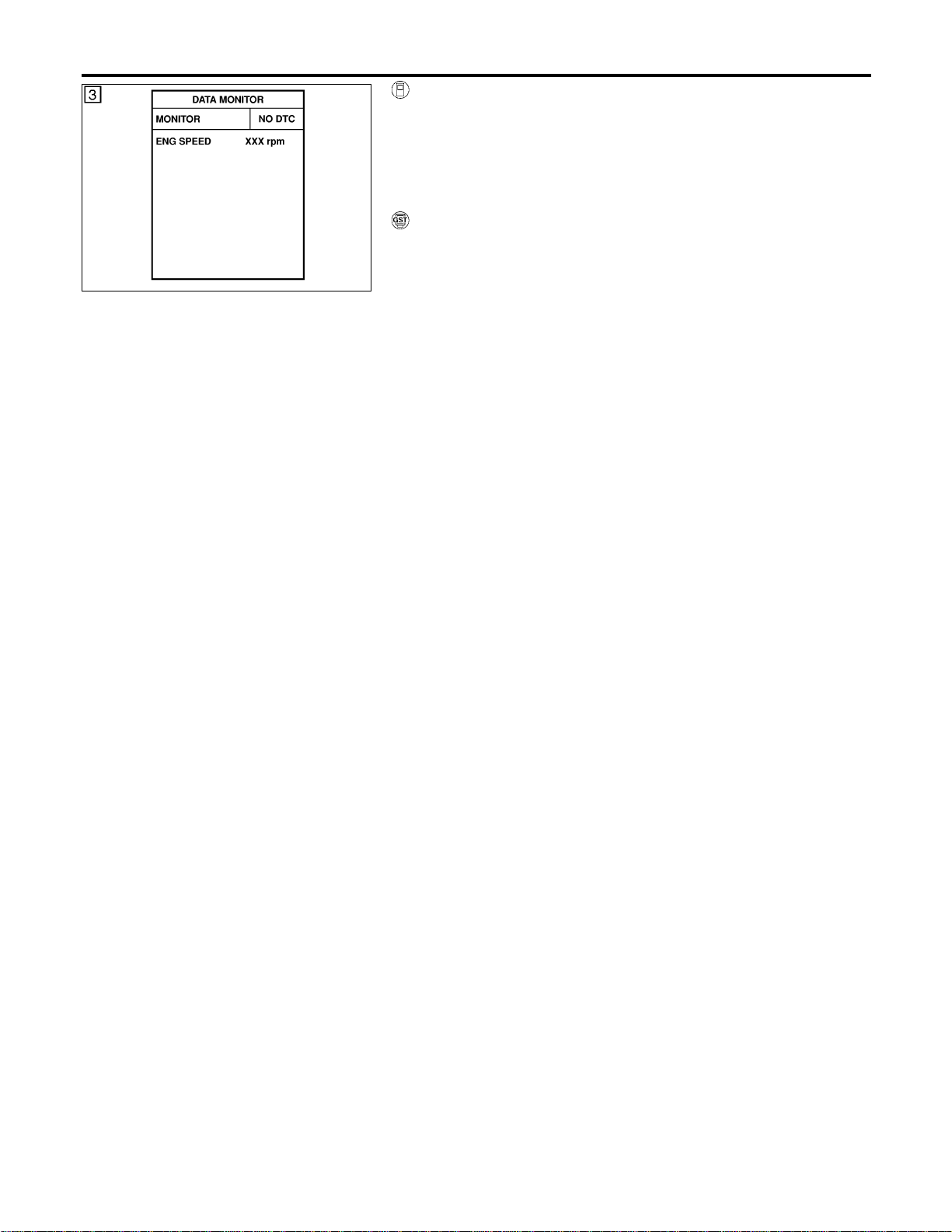
SEF058Y
WITH CONSULT-II
NFEC0974S01
1) Turn ignition switch “ON”.
2) Select “DATA MONITOR” mode with CONSULT-II.
3) Start engine and wait at least 8 seconds.
4) If 1st trip DTC is detected, go to “Diagnostic Procedure”,
EC-386.
WITH GST
NFEC0974S02
Follow the procedure “WITH CONSULT-II” above.
DTC P0447 EVAP CANISTER VENT CONTROL VALVE
DTC Confirmation Procedure (Cont’d)
EC-384
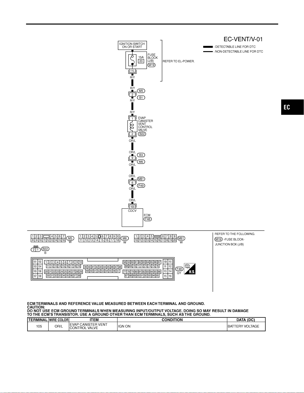
Wiring Diagram
=NFEC0975
MEC495D
SEF668XC
GI
MA
EM
LC
FE
CL
MT
AT
AX
SU
BR
ST
RS
BT
HA
SC
EL
IDX
DTC P0447 EVAP CANISTER VENT CONTROL VALVE
Wiring Diagram
EC-385
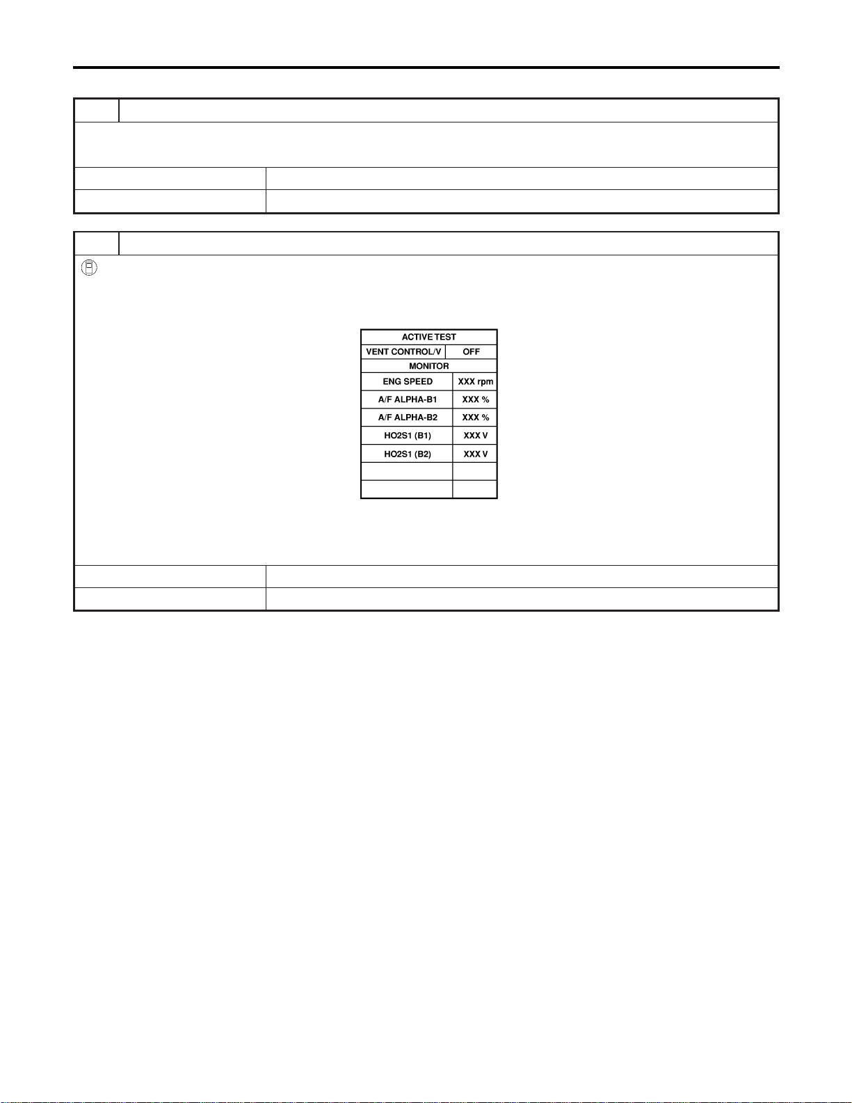
Diagnostic Procedure
NFEC0976
1 INSPECTION START
1. Do you have CONSULT-II?
YesorNo
Yes © GO TO 2.
No © GO TO 3.
2 CHECK EVAP CANISTER VENT CONTROL VALVE CIRCUIT
With CONSULT-II
1. Turn ignition switch “OFF” and then turn “ON”.
2. Select “VENT CONTROL/V” in “ACTIVE TEST” mode with CONSULT-II.
3. Touch “ON/OFF” on CONSULT-II screen.
PBIB0151E
4. Check for operating sound of the valve.
Clicking noise should be heard.
OK or NG
OK © GO TO 7.
NG © GO TO 3.
DTC P0447 EVAP CANISTER VENT CONTROL VALVE
Diagnostic Procedure
EC-386
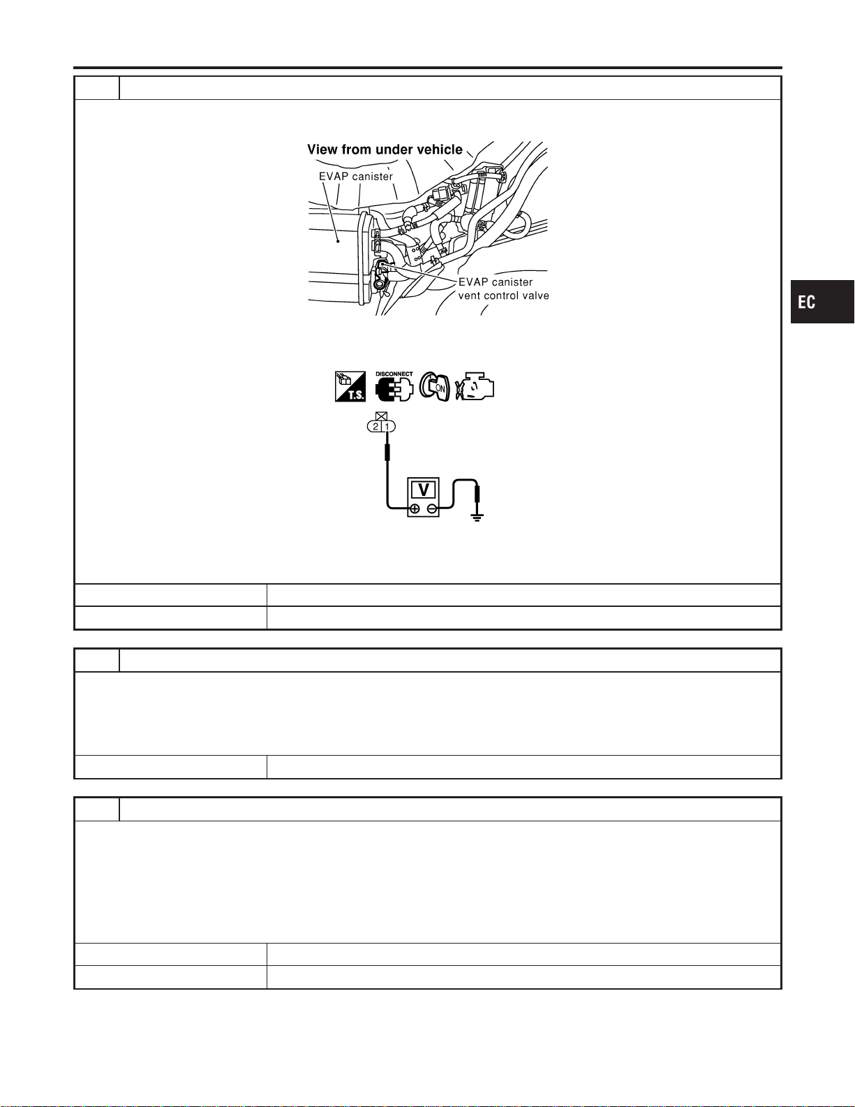
3 CHECK EVAP CANISTER VENT CONTROL VALVE POWER SUPPLY CIRCUIT
1. Turn ignition switch “OFF”.
2. Disconnect EVAP canister vent control valve harness connector.
SEF267X
3. Turn ignition switch “ON”.
4. Check voltage between EVAP canister vent control valve terminal 1 and ground with CONSULT-II or tester.
SEC061D
Voltage: Battery voltage
OK or NG
OK © GO TO 5.
NG © GO TO 4.
4 DETECT MALFUNCTIONING PART
Check the following.
I Harness connectors M5, B1
I Fuse block (J/B) connector M19
I 15A fuse
I Harness for open or short between EVAP canister vent control valve and fuse
© Repair harness or connectors.
5 CHECK EVAP CANISTER VENT CONTROL VALVE OUTPUT SIGNAL CIRCUIT FOR OPEN AND SHORT
1. Turn ignition switch “OFF”.
2. Disconnect ECM harness connector.
3. Check harness continuity between ECM terminal 105 and EVAP canister vent control valve terminal 2.
Refer to Wiring Diagram.
Continuity should exist.
4. Also check harness for short to ground and short to power.
OK or NG
OK © GO TO 7.
NG © GO TO 6.
GI
MA
EM
LC
FE
CL
MT
AT
AX
SU
BR
ST
RS
BT
HA
SC
EL
IDX
DTC P0447 EVAP CANISTER VENT CONTROL VALVE
Diagnostic Procedure (Cont’d)
EC-387
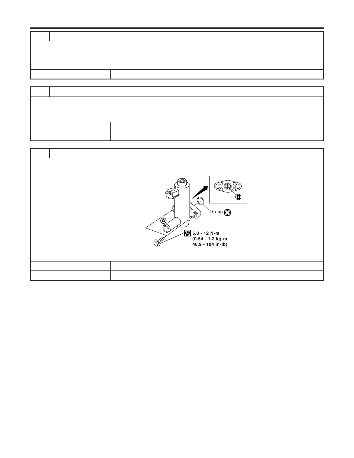
6 DETECT MALFUNCTIONING PART
Check the following.
I Harness connectors B3, M6
I Harness connectors M81, F49
I Harness for open or short between EVAP canister vent control valve and ECM
© Repair open circuit or short to ground or short to power in harness or connectors.
7 CHECK RUBBER TUBE FOR CLOGGING
1. Disconnect rubber tube connected to EVAP canister vent control valve.
2. Check the rubber tube for clogging.
OK or NG
OK © GO TO 8.
NG © Clean the rubber tube using an air blower.
8 CHECK EVAP CANISTER VENT CONTROL VALVE-I
1. Remove EVAP canister vent control valve from EVAP canister.
2. Check portion B of EVAP canister vent control valve for being rusted.
SEF376Z
OK or NG
OK © GO TO 9.
NG © Replace EVAP canister vent control valve.
DTC P0447 EVAP CANISTER VENT CONTROL VALVE
Diagnostic Procedure (Cont’d)
EC-388
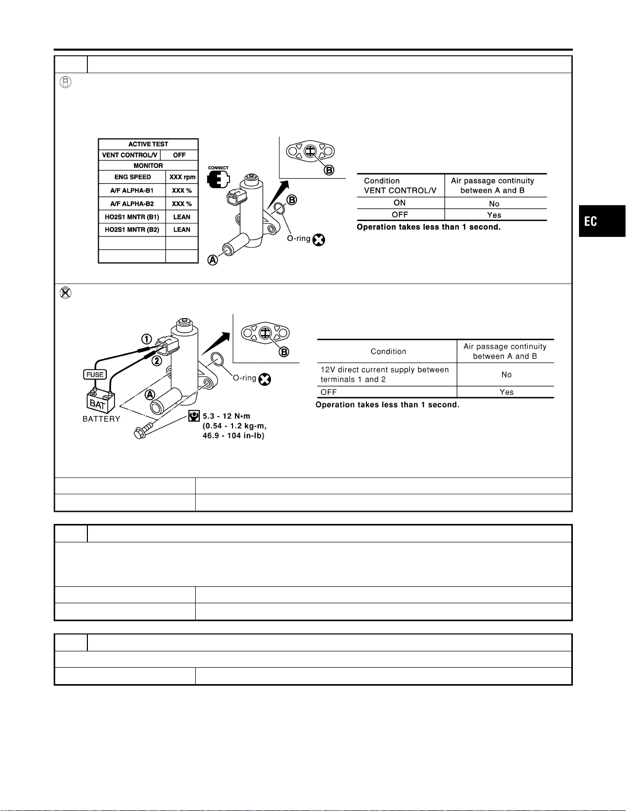
9 CHECK EVAP CANISTER VENT CONTROL VALVE-II
With CONSULT-II
1. Reconnect harness connectors disconnected.
2. Turn ignition switch “ON”.
3. Perform “VENT CONTROL/V” in “ACTIVE TEST” mode.
4. Check air passage continuity and operation delay time.
SEC158D
Without CONSULT-II
Check air passage continuity and operation delay time under the following conditions.
SEF378Z
Make sure new O-ring is installed properly.
OK or NG
OK © GO TO 11.
NG © GO TO 10.
10 CHECK EVAP CANISTER VENT CONTROL VALVE-III
1. Clean the air passage (Portion A to B) of EVAP canister vent control valve using an air blower.
2. Perform Test No. 9 again.
OK or NG
OK © GO TO 11.
NG © Replace EVAP canister vent control valve.
11 CHECK INTERMITTENT INCIDENT
Refer to “TROUBLE DIAGNOSIS FOR INTERMITTENT INCIDENT”, EC-156.
© INSPECTION END
GI
MA
EM
LC
FE
CL
MT
AT
AX
SU
BR
ST
RS
BT
HA
SC
EL
IDX
DTC P0447 EVAP CANISTER VENT CONTROL VALVE
Diagnostic Procedure (Cont’d)
EC-389
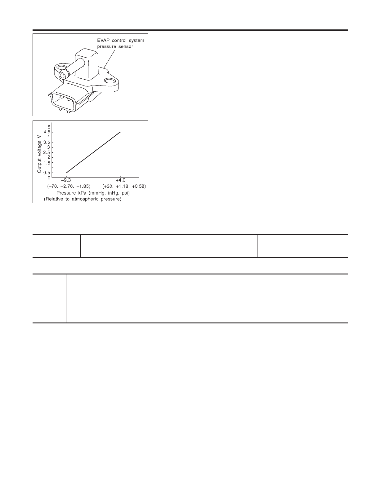
SEF053V
SEF954S
Component Description
NFEC0779
The EVAP control system pressure sensor detects pressure in the
purge line. The sensor output voltage to the ECM increases as
pressure increases. The EVAP control system pressure sensor is
not used to control the engine system. It is used only for on board
diagnosis.
CONSULT-II Reference Value in Data Monitor
Mode
NFEC0780
Specification data are reference values.
MONITOR ITEM CONDITION SPECIFICATION
EVAP SYS PRES I Ignition switch: ON Approx. 3.4V
On Board Diagnosis Logic
NFEC0782
DTC No.
Trouble diagnosis
name
DTC Detecting Condition Possible Cause
P0452
0452
EVAP control system
pressure sensor low
input
An excessively low voltage from the sensor is sent
to ECM.
I Harness or connectors
(The sensor circuit is open or
shorted.)
I EVAP control system pressure sensor
DTC Confirmation Procedure
NFEC0784
NOTE:
If “DTC Confirmation Procedure” has been previously conducted,
always turn ignition switch “OFF” and wait at least 10 seconds
before conducting the next test.
TESTING CONDITION:
Always perform test at a temperature of 5°C (41°F) or more.
DTC P0452 EVAP SYSTEM PRESSURE SENSOR
Component Description
EC-390
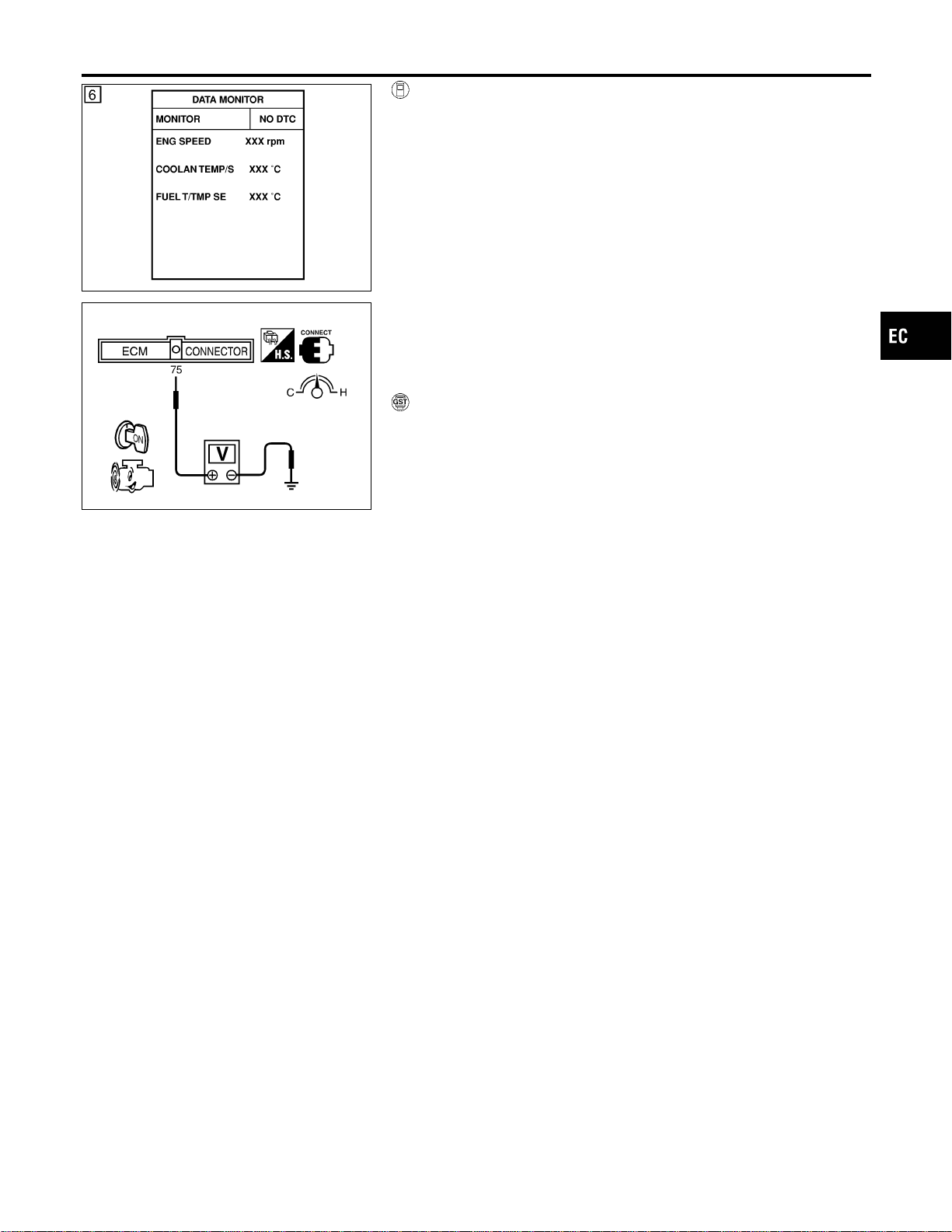
SEF194Y
SEC907C
WITH CONSULT-II
NFEC0784S01
1) Start engine and warm it up to normal operating temperature.
2) Turn ignition switch “OFF” and wait at least 10 seconds.
3) Turn ignition switch “ON”.
4) Select “DATA MONITOR” mode with CONSULT-II.
5) Make sure that “FUEL T/TEMP SE” is more than 0°C (32°F).
6) Start engine and wait at least 20 seconds.
7) If 1st trip DTC is detected, go to “Diagnostic Procedure”,
EC-393.
If 1st trip DTC is not detected, go to next step.
8) Stop engine and install EVAP service port adapter and pres-
sure pump to EVAP service port securely.
9) Pressurize the EVAP line using pressure pump.
10) Confirm the pressure does not go up.
11) If pressure go up, go to “Diagnostic Procedure”, EC-393.
WITH GST
NFEC0784S02
1) Start engine and warm it up to normal operating temperature.
2) Check that voltage between ECM terminal 75 (Fuel tank tem-
perature sensor signal) and ground is less than 4.2V.
3) Turn ignition switch “OFF” and wait at least 10 seconds.
4) Start engine and wait at least 20 seconds.
5) Select “MODE 7” with GST.
6) If 1st trip DTC is detected, go to “Diagnostic Procedure”,
EC-393.
GI
MA
EM
LC
FE
CL
MT
AT
AX
SU
BR
ST
RS
BT
HA
SC
EL
IDX
DTC P0452 EVAP SYSTEM PRESSURE SENSOR
DTC Confirmation Procedure (Cont’d)
EC-391
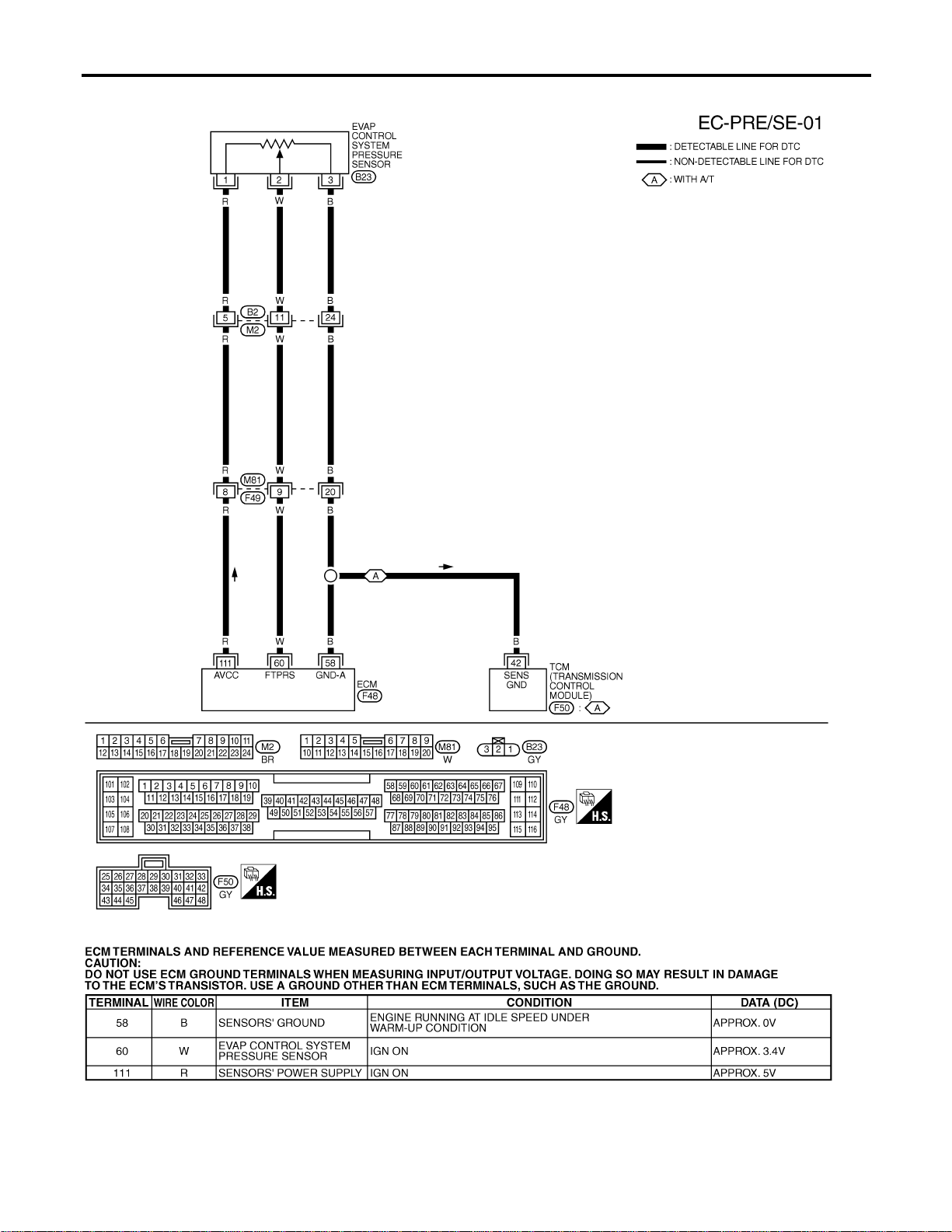
Wiring Diagram
NFEC0785
MEC496D
SEF623XC
DTC P0452 EVAP SYSTEM PRESSURE SENSOR
Wiring Diagram
EC-392
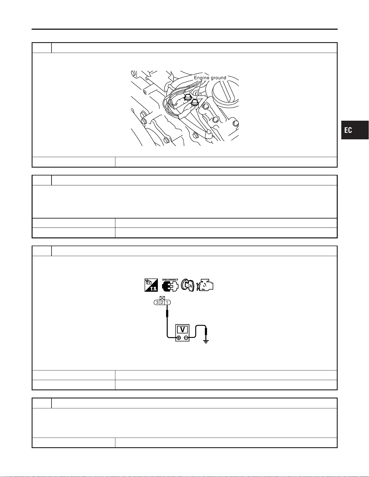
Diagnostic Procedure
NFEC0786
1 RETIGHTEN GROUND SCREWS
1. Turn ignition switch “OFF”.
2. Loosen and retighten engine ground screws.
SEC047D
© GO TO 2.
2 CHECK CONNECTOR
1. Disconnect EVAP control system pressure sensor harness connector.
2. Check sensor harness connector for water.
Water should not exist.
OK or NG
OK © GO TO 3.
NG © Repair or replace harness connector.
3 CHECK EVAP CONTROL SYSTEM PRESSURE SENSOR POWER SUPPLY CIRCUIT
1. Turn ignition switch “ON”.
2. Check voltage between EVAP control system pressure sensor terminal 1 and ground with CONSULT-II or tester.
SEC063D
Voltage: Approximately 5V
OK or NG
OK © GO TO 5.
NG © GO TO 4.
4 DETECT MALFUNCTIONING PART
Check the following.
I Harness connectors B2, M2
I Harness connectors M81, F49
I Harness for open or short between EVAP control system pressure sensor and ECM
© Repair harness or connectors.
GI
MA
EM
LC
FE
CL
MT
AT
AX
SU
BR
ST
RS
BT
HA
SC
EL
IDX
DTC P0452 EVAP SYSTEM PRESSURE SENSOR
Diagnostic Procedure
EC-393
5 CHECK EVAP CONTROL SYSTEM PRESSURE SENSOR GROUND CIRCUIT FOR OPEN AND SHORT
1. Turn ignition switch “OFF”.
2. Check harness continuity between EVAP control system pressure sensor terminal 3 and engine ground.
Refer to Wiring Diagram.
Continuity should exist.
3. Also check harness for short to power.
OK or NG
OK © GO TO 7.
NG © GO TO 6.
6 DETECT MALFUNCTIONING PART
Check the following.
I Harness connectors B2, M2
I Harness connectors M81, F49
I Harness for open between EVAP control system pressure sensor and ECM
I Harness for open between EVAP control system pressure sensor and TCM (Transmission Control Module)
© Repair open circuit or short to power in harness or connectors.
7 CHECK EVAP CONTROL SYSTEM PRESSURE SENSOR INPUT SIGNAL CIRCUIT FOR OPEN AND
SHORT
1. Disconnect ECM harness connector.
2. Check harness continuity between ECM terminal 60 and EVAP control system pressure sensor terminal 2.
Refer to Wiring Diagram.
Continuity should exist.
3. Also check harness for short to ground and short to power.
OK or NG
OK © GO TO 9.
NG © GO TO 8.
8 DETECT MALFUNCTIONING PART
Check the following.
I Harness connectors B2, M2
I Harness connectors M81, F49
I Harness for open or short between ECM and EVAP control system pressure sensor
© Repair open circuit or short to ground or short to power in harness or connectors.
DTC P0452 EVAP SYSTEM PRESSURE SENSOR
Diagnostic Procedure (Cont’d)
EC-394
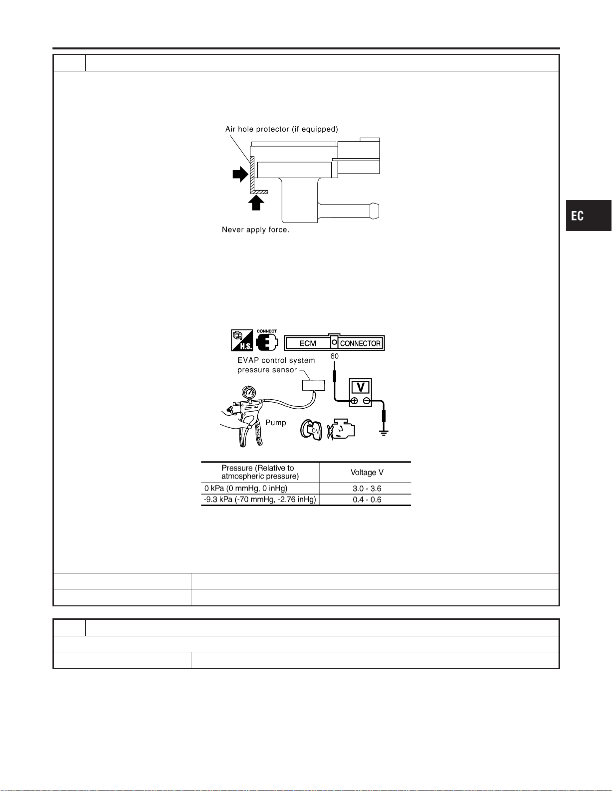
9 CHECK EVAP CONTROL SYSTEM PRESSURE SENSOR
1. Remove EVAP control system pressure sensor with its harness connector connected.
CAUTION:
Never apply force to the air hole protector of the sensor if equipped.
SEF799W
2. Remove hose from EVAP control system pressure sensor.
3. Turn ignition switch “ON”.
4. Use pump to apply vacuum and pressure to EVAP control system pressure sensor as shown in figure.
CAUTION:
I Always calibrate the vacuum pump gauge when using it.
I Do not apply below −20 kPa (−150 mmHg, −5.91 inHg) or over 20 kPa (150 mmHg, 5.91 inHg) of pressure.
5. Check input voltage between ECM terminal 60 and ground.
SEC908C
MTBL1159
CAUTION:
Discard and EVAP control system pressure sensor which has been dropped from a height of more than 0.5 m
(19.7 in) onto a hard surface such as a concrete floor; use a new one.
OK or NG
OK © GO TO 10.
NG © Replace EVAP control system pressure sensor.
10 CHECK INTERMITTENT INCIDENT
Refer to “TROUBLE DIAGNOSIS FOR INTERMITTENT INCIDENT”, EC-156.
© INSPECTION END
GI
MA
EM
LC
FE
CL
MT
AT
AX
SU
BR
ST
RS
BT
HA
SC
EL
IDX
DTC P0452 EVAP SYSTEM PRESSURE SENSOR
Diagnostic Procedure (Cont’d)
EC-395
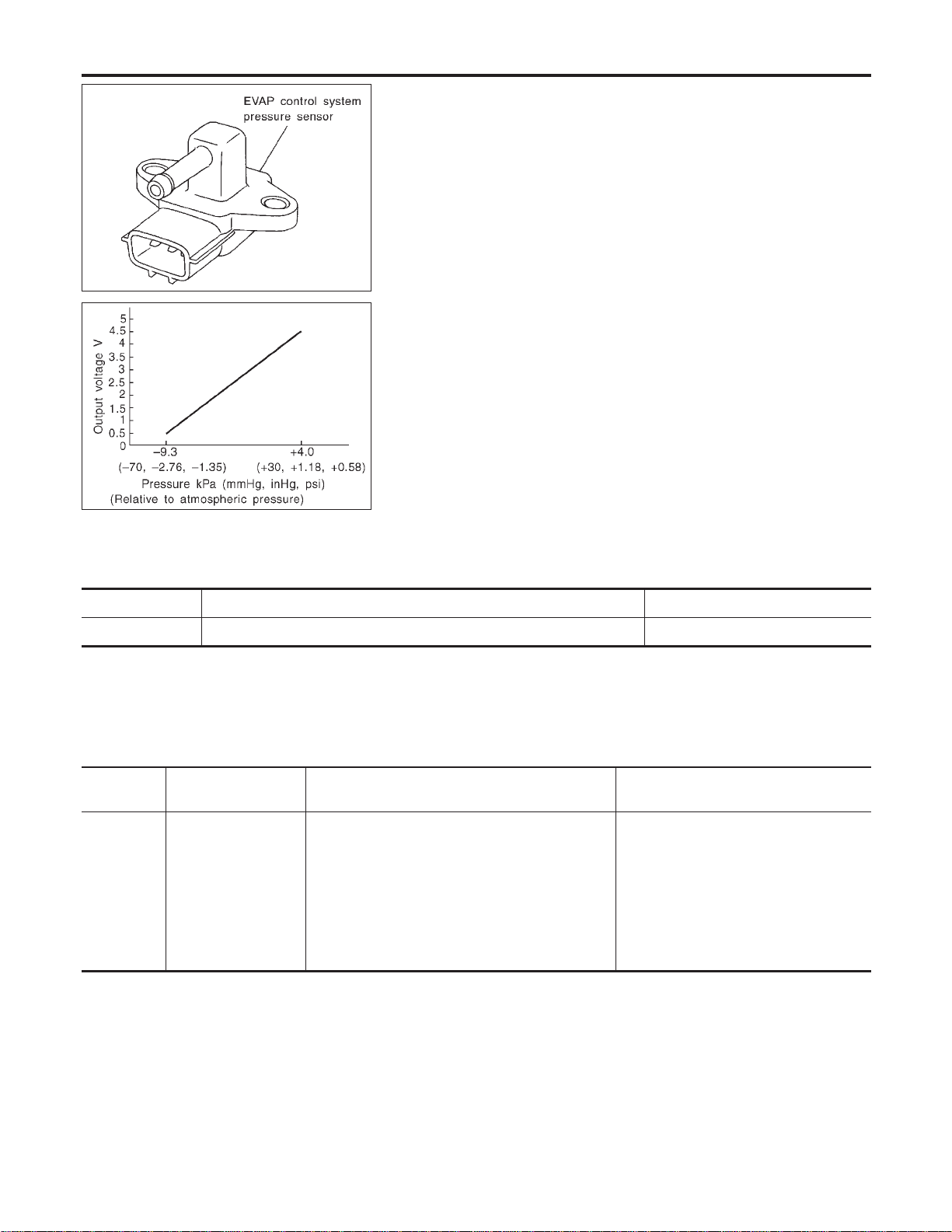
SEF053V
SEF954S
Component Description
NFEC0977
The EVAP control system pressure sensor detects pressure in the
purge line. The sensor output voltage to the ECM increases as
pressure increases. The EVAP control system pressure sensor is
not used to control the engine system. It is used only for on board
diagnosis.
CONSULT-II Reference Value in Data Monitor
Mode
NFEC0978
Specification data are reference values.
MONITOR ITEM CONDITION SPECIFICATION
EVAP SYS PRES I Ignition switch: ON Approx. 3.4V
On Board Diagnosis Logic
NFEC0980
DTC No.
Trouble diagnosis
name
DTC Detecting Condition Possible Cause
P0453
0453
EVAP control system
pressure sensor high
input
An excessively high voltage from the sensor is
sent to ECM.
I Harness or connectors
(The sensor circuit is open or
shorted.)
I EVAP control system pressure sensor
I EVAP canister vent control valve
I EVAP canister
I Water separator
I Rubber hose from EVAP canister vent
control valve to water separator
DTC P0453 EVAP SYSTEM PRESSURE SENSOR
Component Description
EC-396
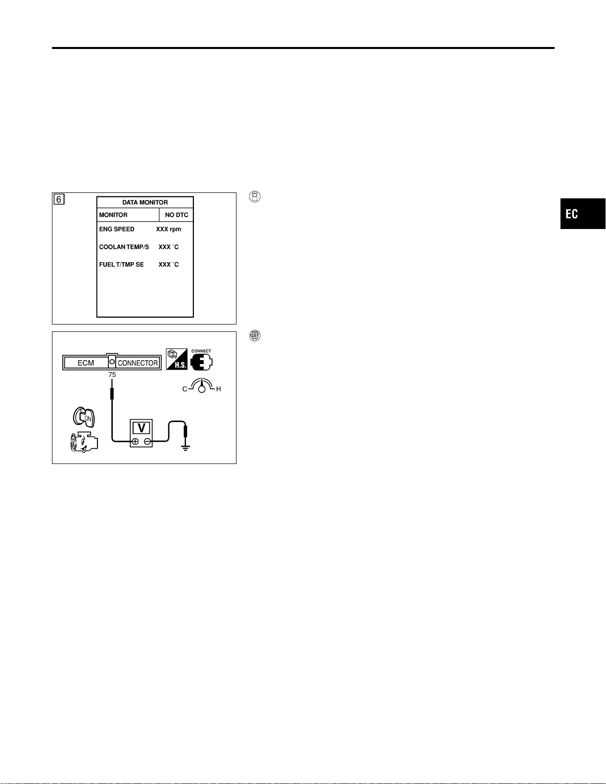
DTC Confirmation Procedure
NFEC0981
NOTE:
If “DTC Confirmation Procedure” has been previously conducted,
always turn ignition switch “OFF” and wait at least 10 seconds
before conducting the next test.
TESTING CONDITION:
Always perform test at a temperature of 5°C (41°F) or more.
SEF194Y
WITH CONSULT-II
NFEC0981S01
1) Start engine and warm it up to normal operating temperature.
2) Turn ignition switch “OFF” and wait at least 10 seconds.
3) Turn ignition switch “ON”.
4) Select “DATA MONITOR” mode with CONSULT-II.
5) Make sure that “FUEL T/TEMP SE” is more than 0°C (32°F).
6) Start engine and wait at least 20 seconds.
7) If 1st trip DTC is detected, go to “Diagnostic Procedure”,
EC-399.
SEC907C
WITH GST
NFEC0981S02
1) Start engine and warm it up to normal operating temperature.
2) Check that voltage between ECM terminal 75 (Fuel tank tem-
perature sensor signal) and ground is less than 4.2V.
3) Turn ignition switch “OFF” and wait at least 10 seconds.
4) Start engine and wait at least 20 seconds.
5) Select “MODE 7” with GST.
6) If 1st trip DTC is detected, go to “Diagnostic Procedure”,
EC-399.
GI
MA
EM
LC
FE
CL
MT
AT
AX
SU
BR
ST
RS
BT
HA
SC
EL
IDX
DTC P0453 EVAP SYSTEM PRESSURE SENSOR
DTC Confirmation Procedure
EC-397
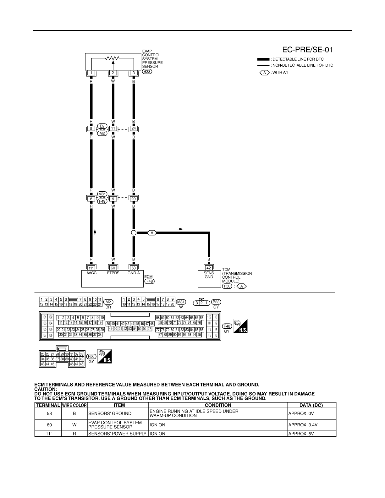
Wiring Diagram
NFEC0982
MEC496D
SEF623XC
DTC P0453 EVAP SYSTEM PRESSURE SENSOR
Wiring Diagram
EC-398
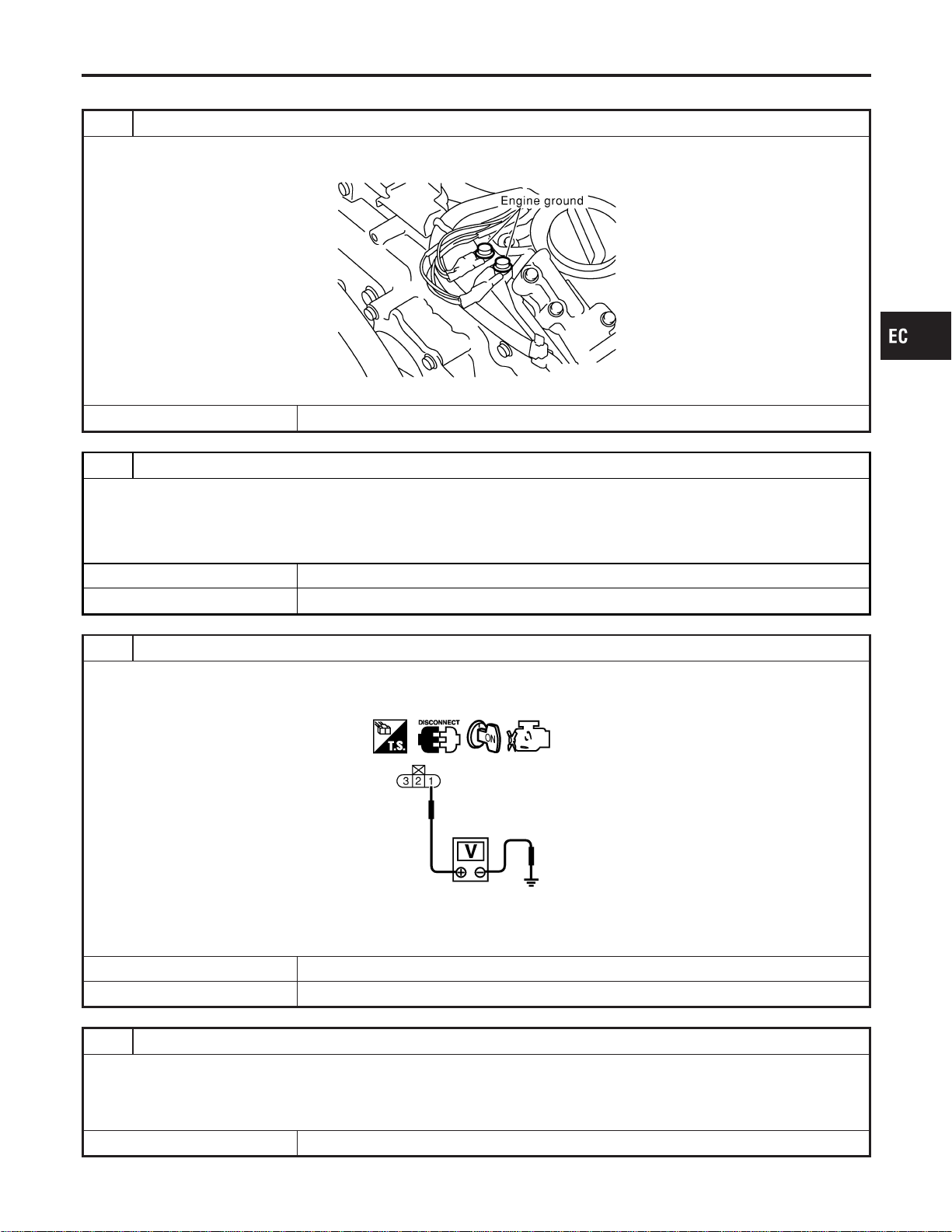
Diagnostic Procedure
NFEC0983
1 RETIGHTEN GROUND SCREWS
1. Turn ignition switch “OFF”.
2. Loosen and retighten engine ground screws.
SEC047D
© GO TO 2.
2 CHECK CONNECTOR
1. Disconnect EVAP control system pressure sensor harness connector.
2. Check sensor harness connector for water.
Water should not exist.
OK or NG
OK © GO TO 3.
NG © Repair or replace harness connector.
3 CHECK EVAP CONTROL SYSTEM PRESSURE SENSOR POWER SUPPLY CIRCUIT
1. Turn ignition switch “ON”.
2. Check voltage between EVAP control system pressure sensor terminal 1 and ground with CONSULT-II or tester.
SEC063D
Voltage: Approximately 5V
OK or NG
OK © GO TO 5.
NG © GO TO 4.
4 DETECT MALFUNCTIONING PART
Check the following.
I Harness connectors B2, M2
I Harness connectors M81, F49
I Harness for open or short between EVAP control system pressure sensor and ECM
© Repair harness or connectors.
GI
MA
EM
LC
FE
CL
MT
AT
AX
SU
BR
ST
RS
BT
HA
SC
EL
IDX
DTC P0453 EVAP SYSTEM PRESSURE SENSOR
Diagnostic Procedure
EC-399
5 CHECK EVAP CONTROL SYSTEM PRESSURE SENSOR GROUND CIRCUIT FOR OPEN AND SHORT
1. Turn ignition switch “OFF”.
2. Check harness continuity between EVAP control system pressure sensor terminal 3 and engine ground.
Refer to Wiring Diagram.
Continuity should exist.
3. Also check harness for short to power.
OK or NG
OK © GO TO 7.
NG © GO TO 6.
6 DETECT MALFUNCTIONING PART
Check the following.
I Harness connectors B2, M2
I Harness connectors M81, F49
I Harness for open between EVAP control system pressure sensor and ECM
I Harness for open between EVAP control system pressure sensor and TCM (Transmission Control Module)
© Repair open circuit or short to power in harness or connectors.
7 CHECK EVAP CONTROL SYSTEM PRESSURE SENSOR INPUT SIGNAL CIRCUIT FOR OPEN AND
SHORT
1. Disconnect ECM harness connector.
2. Check harness continuity between ECM terminal 60 and EVAP control system pressure sensor terminal 2.
Refer to Wiring Diagram.
Continuity should exist.
3. Also check harness for short to ground and short to power.
OK or NG
OK © GO TO 9.
NG © GO TO 8.
8 DETECT MALFUNCTIONING PART
Check the following.
I Harness connectors B2, M2
I Harness connectors M81, F49
I Harness for open or short between ECM and EVAP control system pressure sensor
© Repair open circuit or short to ground or short to power in harness or connectors.
9 CHECK RUBBER TUBE FOR CLOGGING
1. Disconnect rubber tube connected to EVAP canister vent control valve.
2. Check the rubber tube for clogging.
OK or NG
OK © GO TO 10.
NG © Clean the rubber tube using an air blower.
DTC P0453 EVAP SYSTEM PRESSURE SENSOR
Diagnostic Procedure (Cont’d)
EC-400
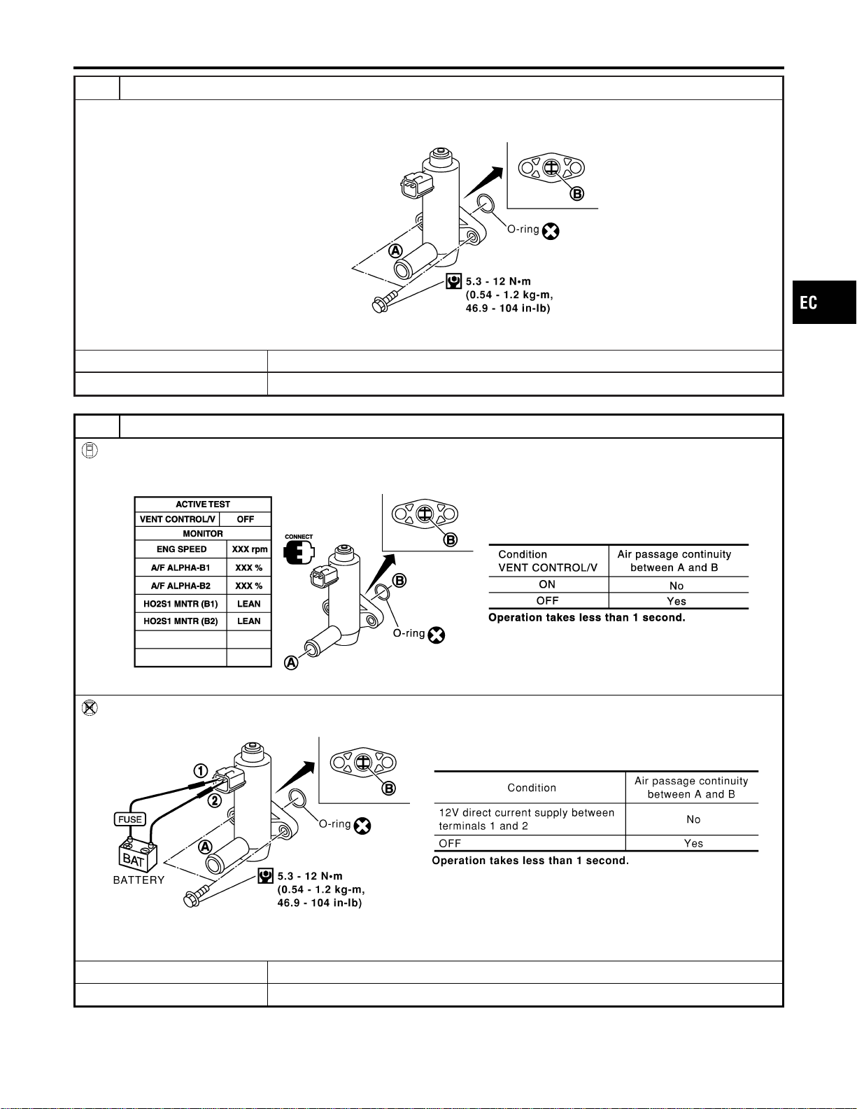
10 CHECK EVAP CANISTER VENT CONTROL VALVE-I
1. Remove EVAP canister vent control valve from EVAP canister.
2. Check portion B of EVAP canister vent control valve for being rusted.
SEF376Z
OK or NG
OK © GO TO 11.
NG © Replace EVAP canister vent control valve.
11 CHECK EVAP CANISTER VENT CONTROL VALVE
With CONSULT-II
1. Perform “VENT CONTROL/V” in “ACTIVE TEST” mode.
2. Check air passage continuity and operation delay time under the following conditions.
SEC158D
Without CONSULT-II
Check air passage continuity and operation delay time under the following conditions.
SEF378Z
Make sure new O-ring is installed properly.
OK or NG
OK © GO TO 13.
NG © GO TO 12.
GI
MA
EM
LC
FE
CL
MT
AT
AX
SU
BR
ST
RS
BT
HA
SC
EL
IDX
DTC P0453 EVAP SYSTEM PRESSURE SENSOR
Diagnostic Procedure (Cont’d)
EC-401
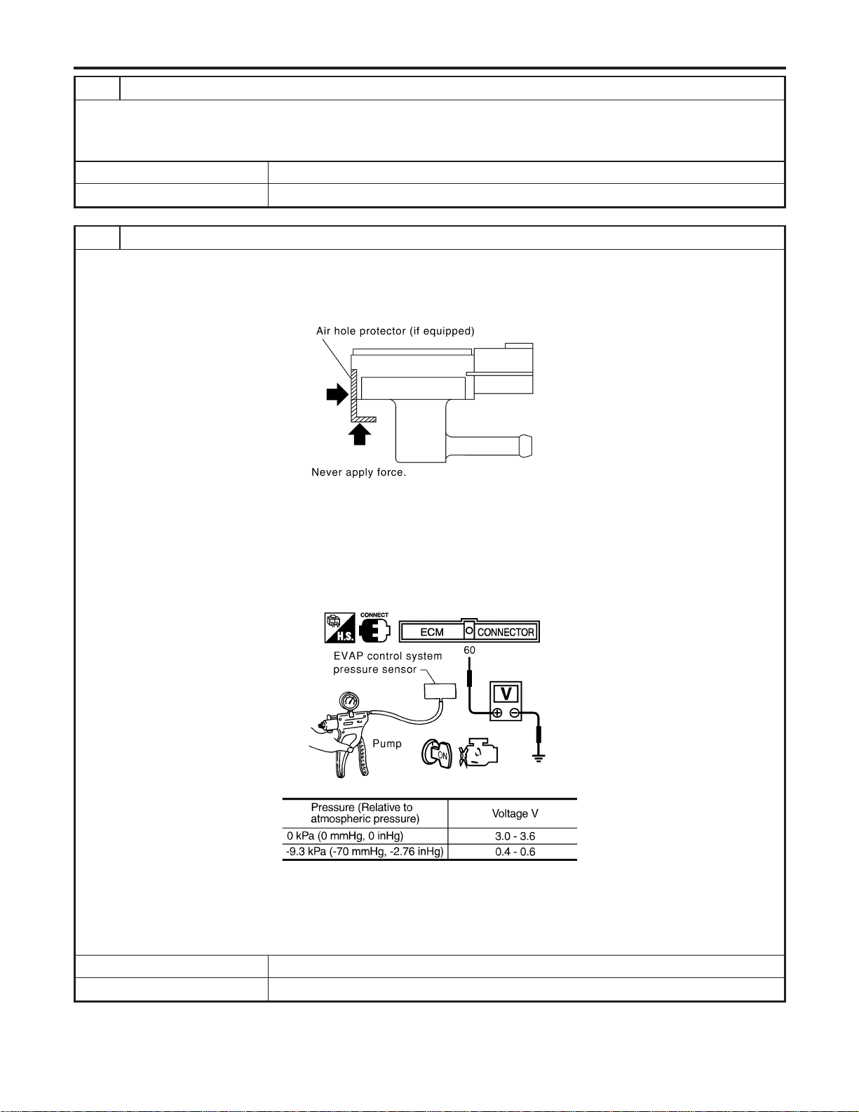
12 CHECK EVAP CANISTER VENT CONTROL VALVE-III
1. Clean the air passage (portion A to B) of EVAP canister vent control valve using an air blower.
2. Perform Test No. 14 again.
OK or NG
OK © GO TO 13.
NG © Replace EVAP canister vent control valve.
13 CHECK EVAP CONTROL SYSTEM PRESSURE SENSOR
1. Remove EVAP control system pressure sensor with its harness connector connected.
CAUTION:
Never apply force to the air hole protector of the sensor if equipped.
SEF799W
2. Remove hose from EVAP control system pressure sensor.
3. Turn ignition switch “ON”.
4. Use pump to apply vacuum and pressure to EVAP control system pressure sensor as shown in figure.
CAUTION:
I Always calibrate the vacuum pump gauge when using it.
I Do not apply below −20 kPa (−150 mmHg, −5.91 inHg) or over 20 kPa (150 mmHg, 5.91 inHg) of pressure.
5. Check input voltage between ECM terminal 60 and ground.
SEC908C
MTBL1159
CAUTION:
Discard and EVAP control system pressure sensor which has been dropped from a height of more than 0.5 m
(19.7 in) onto a hard surface such as a concrete floor; use a new one.
OK or NG
OK © GO TO 14.
NG © Replace EVAP control system pressure sensor.
DTC P0453 EVAP SYSTEM PRESSURE SENSOR
Diagnostic Procedure (Cont’d)
EC-402
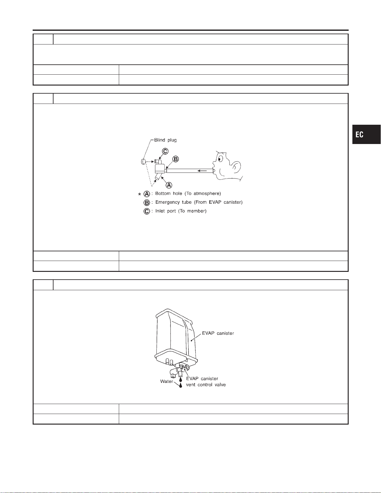
14 CHECK RUBBER TUBE
Check obstructed rubber tube connected to EVAP canister vent control valve.
OK or NG
OK © GO TO 15.
NG © Clean rubber tube using an air blower, repair or replace rubber tube.
15 CHECK WATER SEPARATOR
1. Check visually for insect nests in the water separator air inlet.
2. Check visually for cracks or flaws in the appearance.
3. Check visually for cracks or flaws in the hose.
4. Check that A and C are not clogged by blowing air into B with A, and then C plugged.
SEF829T
5. In case of NG in items2-4,replace the parts.
NOTE:
Do not disassemble water separator.
OK or NG
OK © GO TO 16.
NG © Replace water separator.
16 CHECK IF EVAP CANISTER SATURATED WITH WATER
1. Remove EVAP canister with EVAP canister vent control valve attached.
2. Check if water will drain from the EVAP canister.
SEF596U
YesorNo
Yes © GO TO 17.
No © GO TO 19.
GI
MA
EM
LC
FE
CL
MT
AT
AX
SU
BR
ST
RS
BT
HA
SC
EL
IDX
DTC P0453 EVAP SYSTEM PRESSURE SENSOR
Diagnostic Procedure (Cont’d)
EC-403
17 CHECK EVAP CANISTER
Weigh the EVAP canister with the EVAP canister vent control valve attached.
The weight should be less than 1.8 kg (4.0 lb).
OK or NG
OK © GO TO 19.
NG © GO TO 18.
18 DETECT MALFUNCTIONING PART
Check the following.
I EVAP canister for damage
I EVAP hose between EVAP canister and water separator for clogging or poor connection
© Repair hose or replace EVAP canister.
19 CHECK INTERMITTENT INCIDENT
Refer to “TROUBLE DIAGNOSIS FOR INTERMITTENT INCIDENT”, EC-156.
© INSPECTION END
DTC P0453 EVAP SYSTEM PRESSURE SENSOR
Diagnostic Procedure (Cont’d)
EC-404
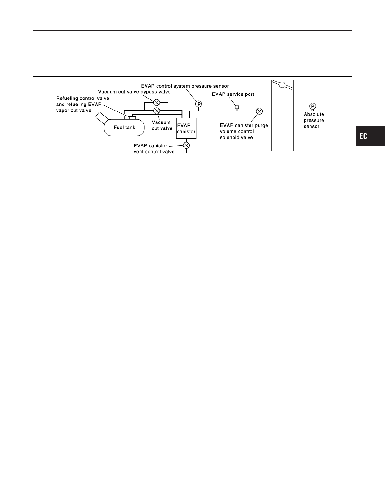
On Board Diagnosis Logic
NFEC1475
NOTE:
If DTC P0455 is displayed with P1448, perform trouble diagnosis for DTC P1448 first. (See EC-594.)
This diagnosis detects a very large leak (fuel filler cap fell off etc.) in EVAP system between the fuel tank and
EVAP canister purge volume control solenoid valve.
SEC936C
Malfunction is detected when EVAP control system has a very large leak such as fuel filler cap fell off, EVAP
control system does not operate properly.
CAUTION:
I Use only a genuine NISSAN fuel filler cap as a replacement. If an incorrect fuel filler cap is used,
the MIL may come on.
I If the fuel filler cap is not tightened properly, the MIL may come on.
I Use only a genuine NISSAN rubber tube as a replacement.
Possible Cause
NFEC1476
I Fuel filler cap remains open or fails to close.
I Incorrect fuel tank vacuum relief valve
I Incorrect fuel filler cap used
I Foreign matter caught in fuel filler cap.
I Leak is in line between intake manifold and EVAP canister
purge volume control solenoid valve.
I Foreign matter caught in EVAP canister vent control valve.
I EVAP canister or fuel tank leaks
I EVAP purge line (pipe and rubber tube) leaks
I EVAP purge line rubber tube bent.
I Blocked or bent rubber tube to EVAP control system pressure
sensor
I Loose or disconnected rubber tube
I EVAP canister vent control valve and the circuit
I EVAP canister purge volume control solenoid valve and the
circuit
I Fuel tank temperature sensor
I O-ring of EVAP canister vent control valve is missing or dam-
aged.
I EVAP control system pressure sensor
GI
MA
EM
LC
FE
CL
MT
AT
AX
SU
BR
ST
RS
BT
HA
SC
EL
IDX
DTC P0455 EVAP CONTROL SYSTEM (GROSS LEAK)
On Board Diagnosis Logic
EC-405
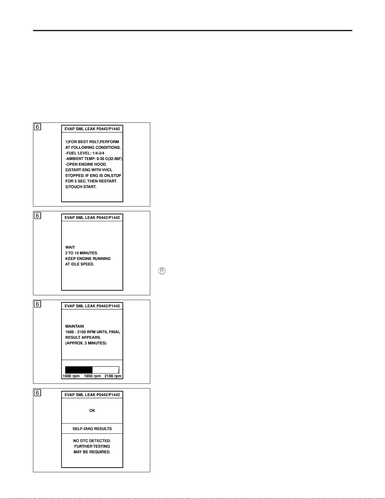
I Refueling control valve
I ORVR system leaks
SEC760C
SEC761C
SEC762C
SEC763C
DTC Confirmation Procedure
NFEC1477
CAUTION:
Never remove fuel filler cap during the DTC Confirmation Pro-
cedure.
NOTE:
I If DTC P0455 is displayed with P1448, perform trouble
diagnosis for DTC P1448 first. (See EC-594.)
I Make sure that EVAP hoses are connected to EVAP canis-
ter purge volume control solenoid valve properly.
I If “DTC Confirmation Procedure” has been previously
conducted, always turn ignition switch “OFF” and wait at least
10 seconds before conducting the next test.
TESTING CONDITION:
I Perform “DTC WORK SUPPORT” when the fuel level is
between 1/4 to 3/4 full and vehicle is placed on flat level
surface.
I Open engine hood before conducting the following proce-
dures.
WITH CONSULT-II
NFEC1477S01
1) Tighten fuel filler cap securely until ratcheting sound is heard.
2) Turn ignition switch “ON”.
3) Turn ignition switch “OFF” and wait at least 10 seconds.
4) Turn ignition switch “ON” and select “DATA MONITOR” mode
with CONSULT-II.
5) Make sure that the following conditions are met.
COOLAN TEMP/S: 0 - 70°C (32 - 158°F)
INT/A TEMP SE: 0 - 60°C (32 - 140°F)
6) Select “EVAP SML LEAK P0442/P1442” of “EVAPORATIVE
SYSTEM” in “DTC WORK SUPPORT” mode with CONSULT-
II.
Follow the instruction displayed.
NOTE:
If the engine speed cannot be maintained within the range dis-
played on the CONSULT-II screen, go to “Basic Inspection”,
EC-123.
7) Make sure that “OK” is displayed.
If “NG” is displayed, select “SELF-DIAG RESULTS” mode and
make sure that “EVAP GROSS LEAK [P0455]” is displayed. If
it is displayed, refer to “Diagnostic Procedure”, EC-407.
If P0442 is displayed, perform “Diagnostic Procedure” for DTC
P0442.
DTC P0455 EVAP CONTROL SYSTEM (GROSS LEAK)
Possible Cause (Cont’d)
EC-406
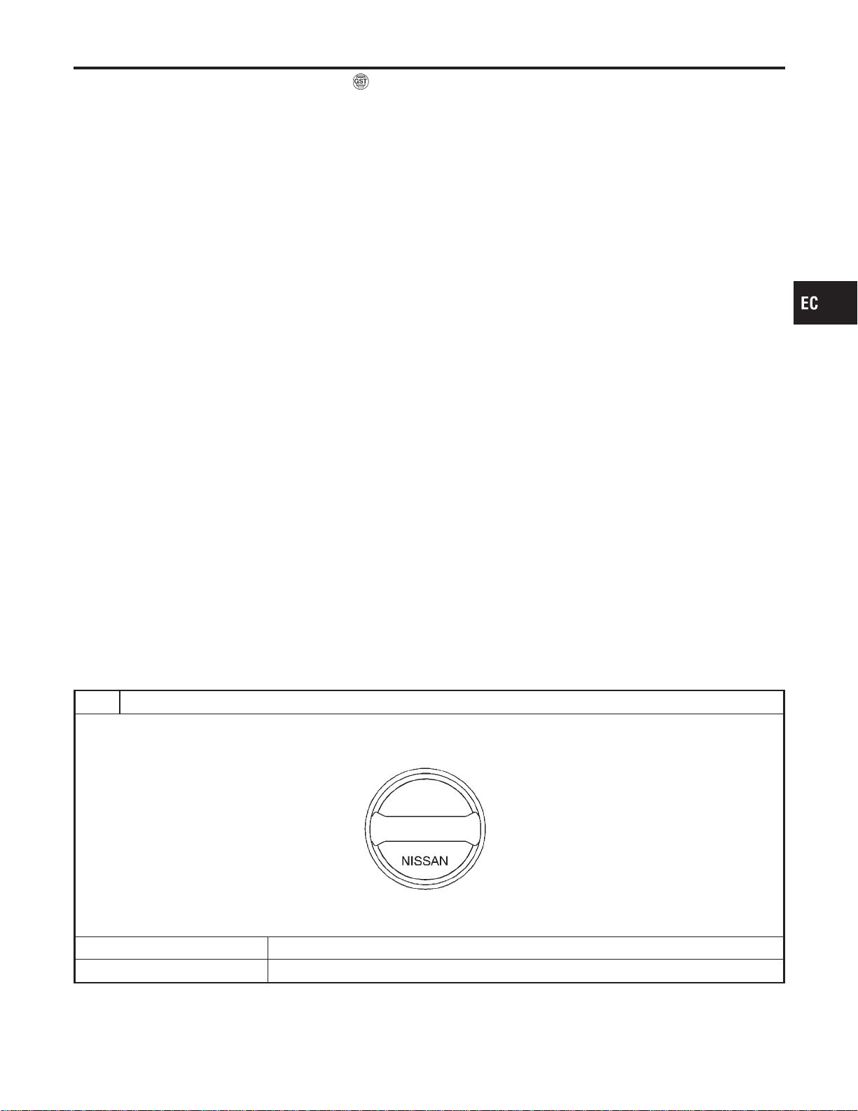
WITH GST
NFEC1477S02
NOTE:
Be sure to read the explanation of “Driving Pattern” on EC-83
before driving vehicle.
1) Start engine.
2) Drive vehicle according to “Driving Pattern”, EC-83.
3) Stop vehicle.
4) Select “MODE 1” with GST.
I If SRT of EVAP system is not set yet, go to the following step.
I If SRT of EVAP system is set, the result will be OK.
5) Turn ignition switch “OFF” and wait at least 10 seconds.
6) Start engine.
It is not necessary to cool engine down before driving.
7) Drive vehicle again according to the “Driving Pattern”, EC-83.
8) Stop vehicle.
9) Select “MODE 3” with GST.
I If P0455 is displayed on the screen, go to “Diagnostic
Procedure”, EC-407.
I If P0442 is displayed on the screen, go to “Diagnostic
Procedure”, for DTC P0442, EC-363.
I If P0441 is displayed on the screen, go to “Diagnostic Proce-
dure” for DTC P0441, EC-354.
I If P0455, P0442 and P0441 are not displayed on the screen,
go to the following step.
10) Select “MODE 1” with GST.
I If SRT of EVAP system is set, the result will be OK.
I If SRT of EVAP system is not set, go to step 6.
Diagnostic Procedure
NFEC1478
1 CHECK FUEL FILLER CAP DESIGN
1. Turn ignition switch “OFF”.
2. Check for genuine NISSAN fuel filler cap design.
SEF915U
OK or NG
OK © GO TO 2.
NG © Replace with genuine NISSAN fuel filler cap.
GI
MA
EM
LC
FE
CL
MT
AT
AX
SU
BR
ST
RS
BT
HA
SC
EL
IDX
DTC P0455 EVAP CONTROL SYSTEM (GROSS LEAK)
DTC Confirmation Procedure (Cont’d)
EC-407
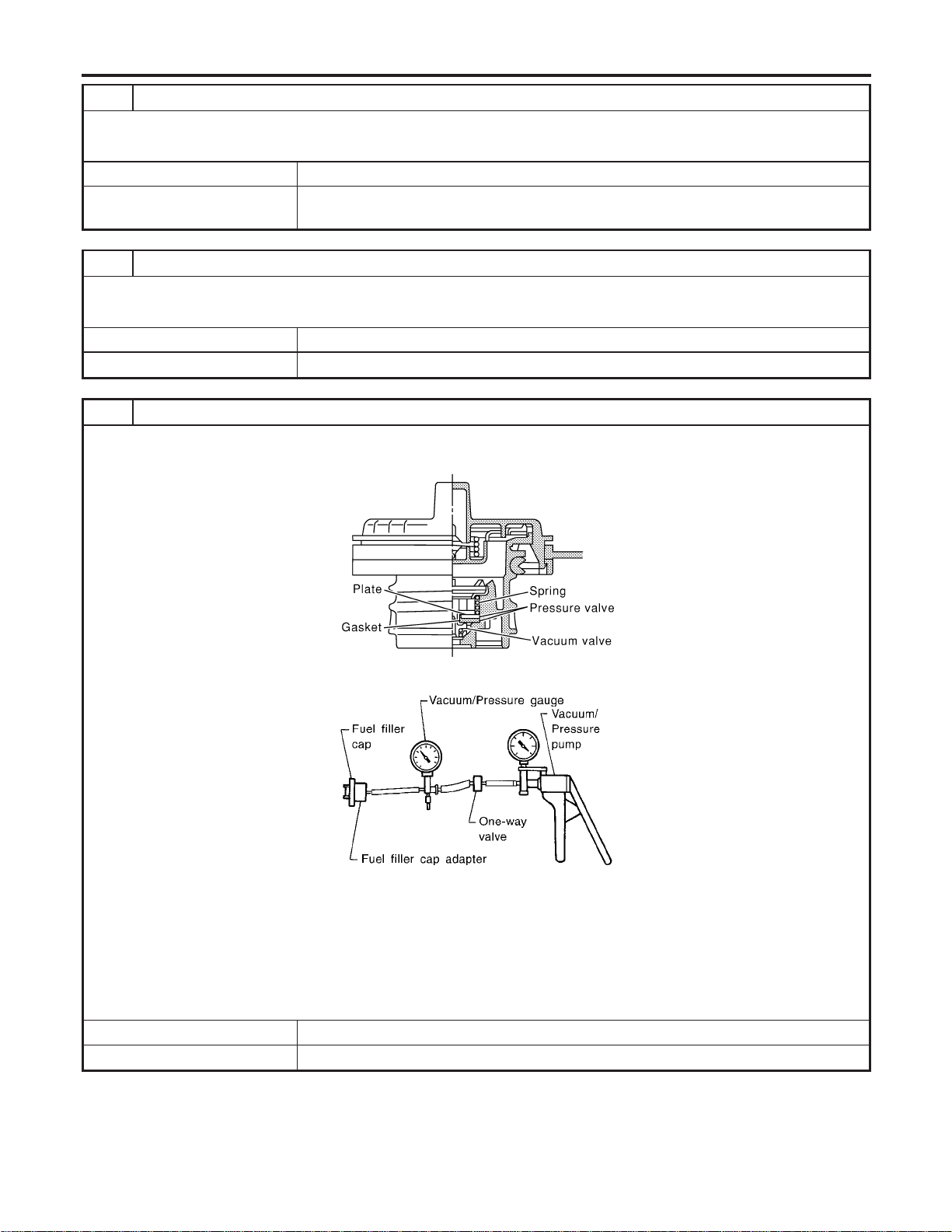
2 CHECK FUEL FILLER CAP INSTALLATION
Check that the cap is tightened properly by rotating the cap clockwise.
OK or NG
OK © GO TO 3.
NG © I Open fuel filler cap, then clean cap and fuel filler neck threads using air blower.
I Retighten until ratcheting sound is heard.
3 CHECK FUEL FILLER CAP FUNCTION
Check for air releasing sound while opening the fuel filler cap.
OK or NG
OK © GO TO 5.
NG © GO TO 4.
4 CHECK FUEL TANK VACUUM RELIEF VALVE
1. Wipe clean valve housing.
2. Check valve opening pressure and vacuum.
SEF445Y
SEF943S
Pressure:
15.3 - 20.0 kPa (0.156 - 0.204 kg/cm
2
, 2.22 - 2.90 psi)
Vacuum:
−6.0 to −3.3 kPa (−0.061 to −0.034 kg/cm
2
, −0.87 to −0.48 psi)
CAUTION:
Use only a genuine fuel filler cap as a replacement. If an incorrect fuel filler cap is used, the MIL may come on.
OK or NG
OK © GO TO 5.
NG © Replace fuel filler cap with a genuine one.
DTC P0455 EVAP CONTROL SYSTEM (GROSS LEAK)
Diagnostic Procedure (Cont’d)
EC-408
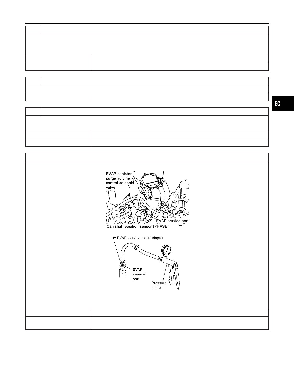
5 CHECK EVAP PURGE LINE
Check EVAP purge line (pipe, rubber tube, fuel tank and EVAP canister) for cracks, improper connection or disconnection.
Refer to “Evaporative Emission System”, EC-36.
OK or NG
OK © GO TO 6.
NG © Repair or reconnect the hose.
6 CLEAN EVAP PURGE LINE
Clean EVAP purge line (pipe and rubber tube) using air blower.
© GO TO 7.
7 CHECK EVAP CANISTER VENT CONTROL VALVE, O-RING AND CIRCUIT
Refer to “DTC Confirmation Procedure”, EC-383.
OK or NG
OK © GO TO 8.
NG © Repair or replace EVAP canister vent control valve and O-ring or harness/connector.
8 INSTALL THE PRESSURE PUMP
To locate the EVAP leak, install EVAP service port adapter and pressure pump to EVAP service port securely.
SEC929C
SEF916U
NOTE:
Improper installation of the EVAP service port adapter to the EVAP service port may cause leaking.
Models with CONSULT-II © GO TO 9.
Models without CON-
SULT-II
© GO TO 10.
GI
MA
EM
LC
FE
CL
MT
AT
AX
SU
BR
ST
RS
BT
HA
SC
EL
IDX
DTC P0455 EVAP CONTROL SYSTEM (GROSS LEAK)
Diagnostic Procedure (Cont’d)
EC-409

9 CHECK FOR EVAP LEAK
With CONSULT-II
1. Turn ignition switch “ON”.
2. Select “EVAP SYSTEM CLOSE” of “WORK SUPPORT” mode with CONSULT-II.
3. Touch “START” and apply pressure into the EVAP line until the pressure indicator reaches the middle of the bar graph.
NOTE:
I Never use compressed air or a high pressure pump.
I Do not exceed 4.12 kPa (0.042 kg/cm
2
, 0.6 psi) of pressure in the system.
PEF917U
4. Using EVAP leak detector, locate the EVAP leak. For the leak detector, refer to the instruction manual for more details.
Refer to “EVAPORATIVE EMISSION LINE DRAWING”, EC-40.
SEF200U
OK or NG
OK © GO TO 11.
NG © Repair or replace.
DTC P0455 EVAP CONTROL SYSTEM (GROSS LEAK)
Diagnostic Procedure (Cont’d)
EC-410
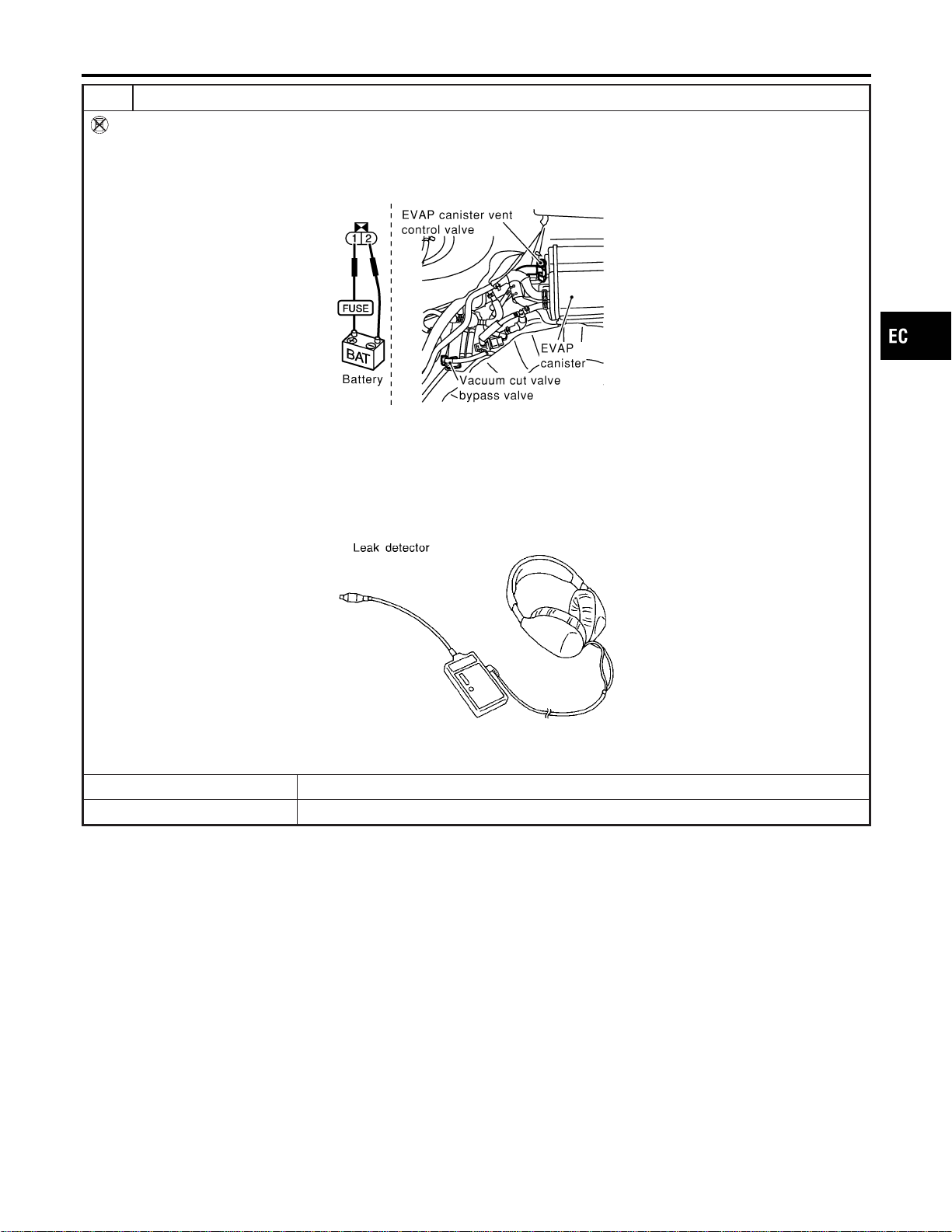
10 CHECK FOR EVAP LEAK
Without CONSULT-II
1. Turn ignition switch “OFF”.
2. Apply 12 volts DC to EVAP canister vent control valve. The valve will close. (Continue to apply 12 volts until the end of
test.)
3. Apply 12 volts DC to vacuum cut valve bypass valve. The valve will open. (Continue to apply 12V until the end of test.)
SEF254X
4. Pressurize the EVAP line using pressure pump with 1.3 to 2.7 kPa (10 to 20 mmHg, 0.39 to 0.79 inHg), then remove
pump and EVAP service port adapter.
NOTE:
I Never use compressed air or a high pressure pump.
I Do not exceed 4.12 kPa (0.042 kg/cm
2
, 0.6 psi) of pressure in the system.
5. Using EVAP leak detector, locate the EVAP leak. For the leak detector, refer to the instruction manual for more details.
Refer to “EVAPORATIVE EMISSION LINE DRAWING”, EC-40.
SEF200U
OK or NG
OK © GO TO 12.
NG © Repair or replace.
GI
MA
EM
LC
FE
CL
MT
AT
AX
SU
BR
ST
RS
BT
HA
SC
EL
IDX
DTC P0455 EVAP CONTROL SYSTEM (GROSS LEAK)
Diagnostic Procedure (Cont’d)
EC-411
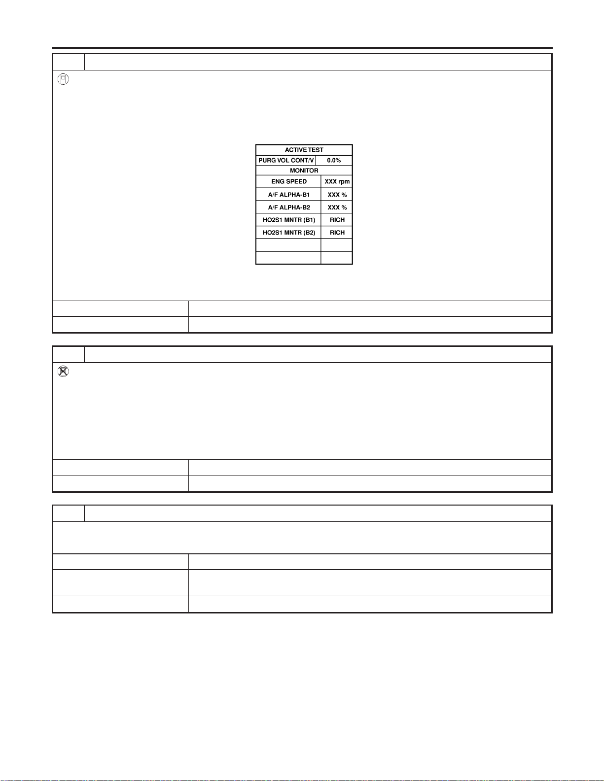
11 CHECK EVAP CANISTER PURGE VOLUME CONTROL SOLENOID VALVE OPERATION
With CONSULT-II
1. Disconnect vacuum hose to EVAP canister purge volume control solenoid valve at EVAP service port.
2. Start engine.
3. Perform “PURG VOL CONT/V” in “ACTIVE TEST” mode.
4. Touch “Qu” on CONSULT-II screen to increase “PURG VOL CONT/V” opening to 100.0%.
5. Check vacuum hose for vacuum when revving engine up to 2,000 rpm.
SEC142D
Vacuum should exist.
OK or NG
OK © GO TO 14.
NG © GO TO 13.
12 CHECK EVAP CANISTER PURGE VOLUME CONTROL SOLENOID VALVE OPERATION
Without CONSULT-II
1. Start engine and warm it up to normal operating temperature.
2. Stop engine.
3. Disconnect vacuum hose to EVAP canister purge volume control solenoid valve at EVAP service port.
4. Start engine and let it idle for at least 80 seconds.
5. Check vacuum hose for vacuum when revving engine up to 2,000 rpm.
Vacuum should exist.
OK or NG
OK © GO TO 15.
NG © GO TO 13.
13 CHECK VACUUM HOSE
Check vacuum hoses for clogging or disconnection. Refer to “Vacuum Hose Drawing”, EC-30.
OK or NG
OK (With CONSULT-II) © GO TO 14.
OK (Without CONSULT-
II)
© GO TO 15.
NG © Repair or reconnect the hose.
DTC P0455 EVAP CONTROL SYSTEM (GROSS LEAK)
Diagnostic Procedure (Cont’d)
EC-412
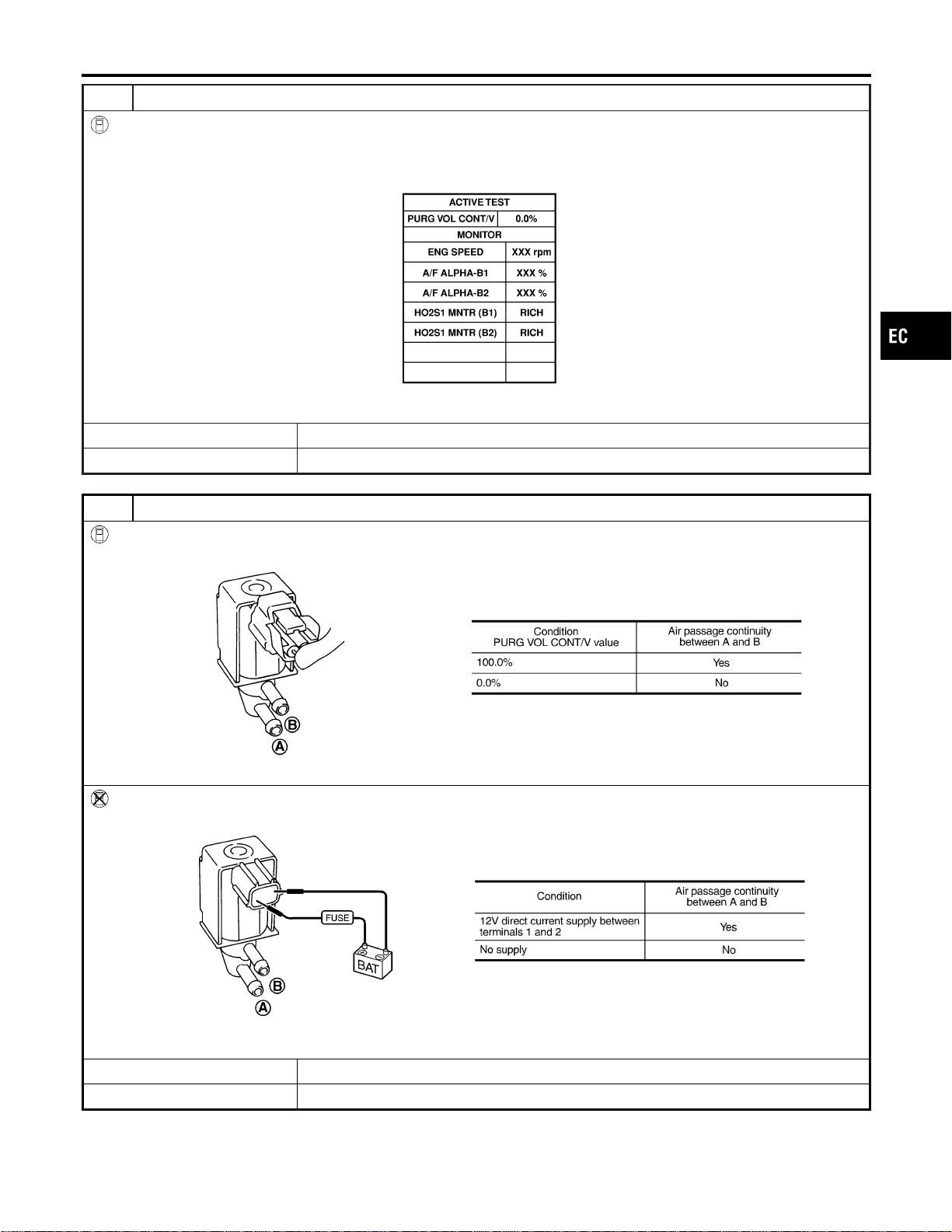
14 CHECK EVAP CANISTER PURGE VOLUME CONTROL SOLENOID VALVE
With CONSULT-II
1. Start engine.
2. Perform “PURG VOL CONT/V” in “ACTIVE TEST” mode with CONSULT-II. Check that engine speed varies according
to the valve opening.
SEC142D
OK or NG
OK © GO TO 16.
NG © GO TO 15.
15 CHECK EVAP CANISTER PURGE VOLUME CONTROL SOLENOID VALVE
With CONSULT-II
Check air passage continuity of EVAP canister purge volume control solenoid valve under the following conditions.
SEF334X
Without CONSULT-II
Check air passage continuity of EVAP canister purge volume control solenoid valve under the following conditions.
SEF335X
OK or NG
OK © GO TO 16.
NG © Replace EVAP canister purge volume control solenoid valve.
GI
MA
EM
LC
FE
CL
MT
AT
AX
SU
BR
ST
RS
BT
HA
SC
EL
IDX
DTC P0455 EVAP CONTROL SYSTEM (GROSS LEAK)
Diagnostic Procedure (Cont’d)
EC-413
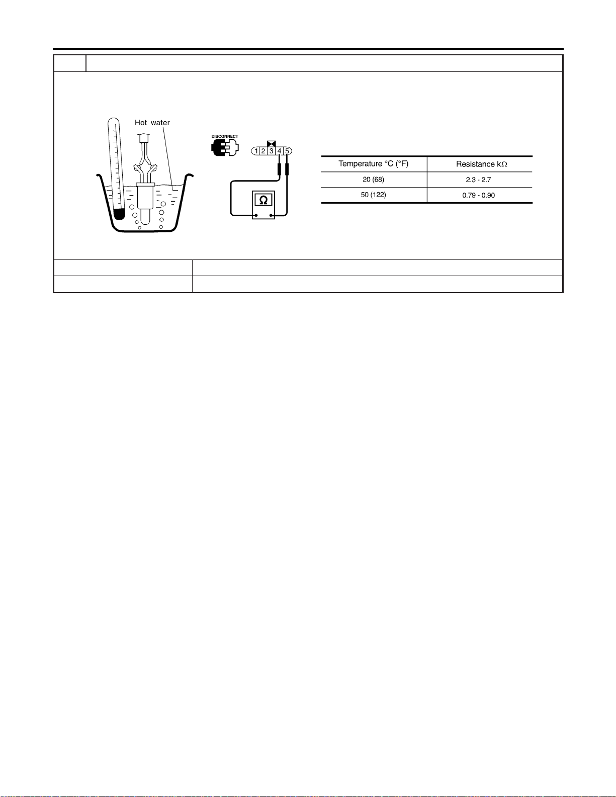
16 CHECK FUEL TANK TEMPERATURE SENSOR
1. Remove fuel level sensor unit.
2. Check resistance between fuel level sensor unit and fuel pump terminals 4 and 5 by heating with hot water or heat gun
as shown in the figure.
SEF587X
OK or NG
OK © GO TO 17.
NG © Replace fuel level sensor unit.
DTC P0455 EVAP CONTROL SYSTEM (GROSS LEAK)
Diagnostic Procedure (Cont’d)
EC-414
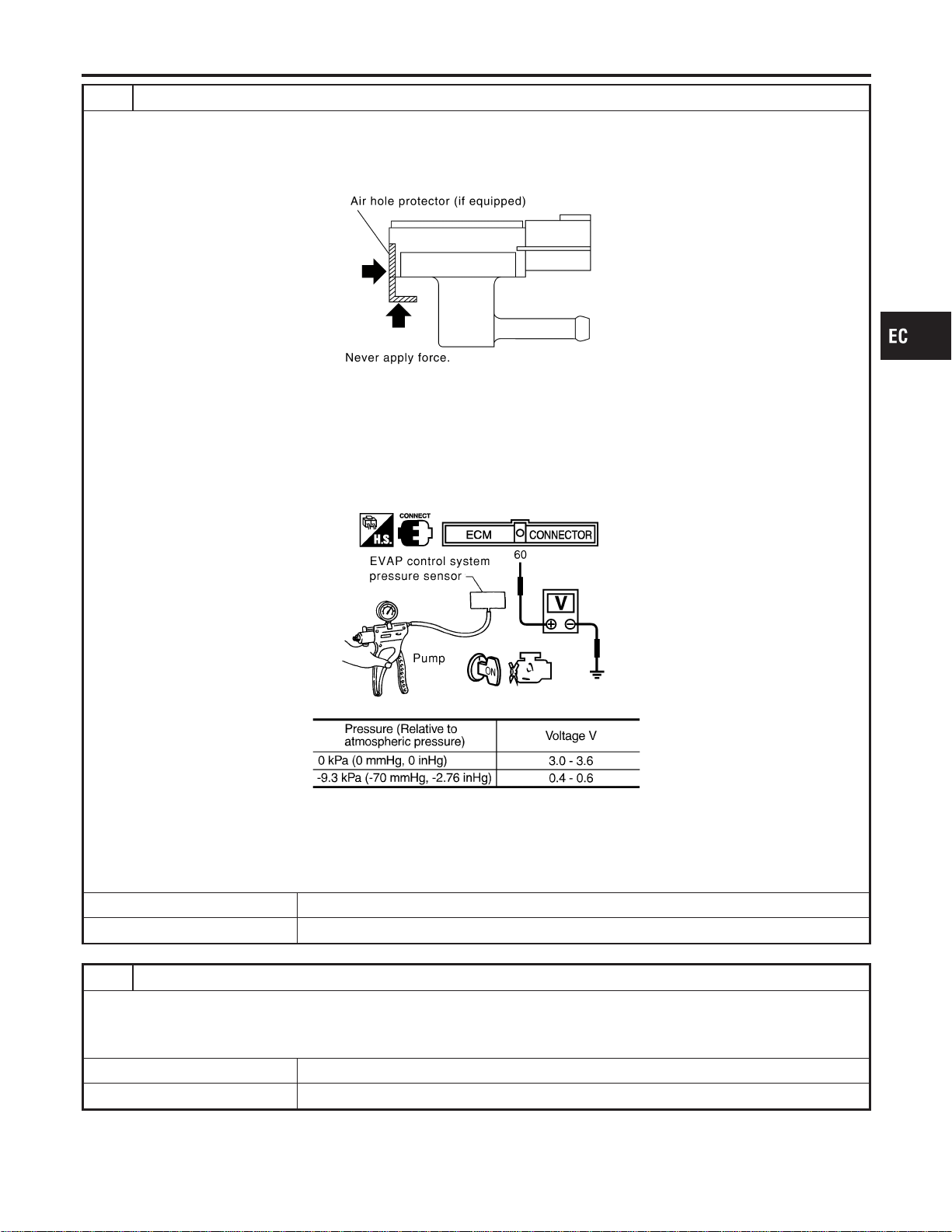
17 CHECK EVAP CONTROL SYSTEM PRESSURE SENSOR
1. Remove EVAP control system pressure sensor with its harness connector connected.
CAUTION:
Never apply force to the air hole protector of the sensor if equipped.
SEF799W
2. Remove hose from EVAP control system pressure sensor.
3. Turn ignition switch “ON”.
4. Use pump to apply vacuum and pressure to EVAP control system pressure sensor as shown in figure.
CAUTION:
I Always calibrate the vacuum pump gauge when using it.
I Do not apply below −20 kPa (−150 mmHg, −5.91 inHg) or over 20 kPa (150 mmHg, 5.91 inHg) of pressure.
5. Check input voltage between ECM terminal 60 and ground.
SEC908C
MTBL1159
CAUTION:
Discard and EVAP control system pressure sensor which has been dropped from a height of more than 0.5 m
(19.7 in) onto a hard surface such as a concrete floor; use a new one.
OK or NG
OK © GO TO 18.
NG © Replace EVAP control system pressure sensor.
18 CHECK REFUELING EVAP VAPOR LINE
Check refueling EVAP vapor line between EVAP canister and fuel tank for clogging, kink, looseness and improper connec-
tion. For location, refer to “ON BOARD REFUELING VAPOR RECOVERY (ORVR)”, EC-42.
OK or NG
OK © GO TO 19.
NG © Repair or replace hoses and tubes.
GI
MA
EM
LC
FE
CL
MT
AT
AX
SU
BR
ST
RS
BT
HA
SC
EL
IDX
DTC P0455 EVAP CONTROL SYSTEM (GROSS LEAK)
Diagnostic Procedure (Cont’d)
EC-415
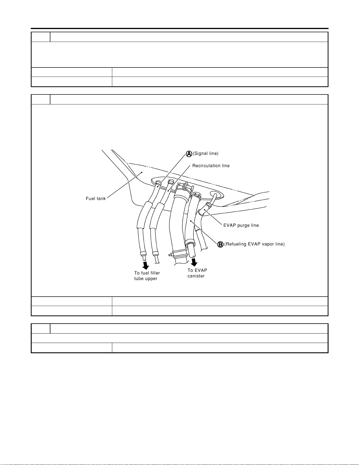
19 CHECK SIGNAL LINE AND RECIRCULATION LINE
Check signal line and recirculation line between filler neck tube and fuel tank for clogging, kink, cracks, looseness and
improper connection.
OK or NG
OK © GO TO 20.
NG © Repair or replace hoses, tubes or filler neck tube.
20 CHECK REFUELING CONTROL VALVE
1. Remove fuel filler cap.
2. Check air continuity between hose ends A and B.
Blow air into the hose end B. Air should flow freely into the fuel tank.
3. Blow air into hose end A and check there is no leakage.
4. Apply pressure to both hose ends A and B [20 kPa (150 mmHg, 5.91 inHg)] using a pressure pump and a suitable
3-way connector. Check that there is no leakage.
SEF830X
OK or NG
OK © GO TO 21.
NG © Replace refueling control valve with fuel tank.
21 CHECK INTERMITTENT INCIDENT
Refer to “TROUBLE DIAGNOSIS FOR INTERMITTENT INCIDENT”, EC-156.
© INSPECTION END
DTC P0455 EVAP CONTROL SYSTEM (GROSS LEAK)
Diagnostic Procedure (Cont’d)
EC-416
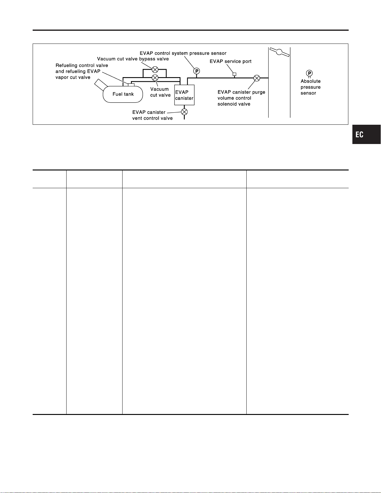
On Board Diagnosis Logic
NFEC0987
SEC936C
This diagnosis detects very small leaks in the EVAP line between fuel tank and EVAP canister purge volume
control solenoid valve, using the intake manifold same as a conventional EVAP small leak diagnosis.
If ECM judges a leak which corresponds to a very small leak, the very small leak P0456 will be detected.
If ECM judges a leak equivalent to a small leak, EVAP small leak P0442 will be detected.
If ECM judges there are no leaks, the diagnosis will be OK.
DTC No.
Trouble diagnosis
name
DTC Detecting Condition Possible Cause
P0456
0456
Evaporative emission
control system very
small leak (negative
pressure check)
I EVAP system has a very small leak.
I EVAP system does not operate properly.
I Incorrect fuel tank vacuum relief valve
I Incorrect fuel filler cap used
I Fuel filler cap remains open or fails to
close.
I Foreign matter caught in fuel filler cap
I Leak is in line between intake mani-
fold and EVAP canister purge volume
control solenoid valve.
I Foreign matter caught in EVAP canis-
ter vent control valve
I EVAP canister or fuel tank leaks
I EVAP purge line (Pipe and rubber
tube) leaks
I EVAP purge line rubber tube bent
I Blocked or bent rubber tube to EVAP
control system pressure sensor
I Loose or disconnected rubber tube
I EVAP canister vent control valve and
the circuit
I EVAP canister purge volume control
solenoid valve and the circuit
I Absolute pressure sensor
I Fuel tank temperature sensor
I O-ring of EVAP canister vent control
valve is missing or damaged.
I Water separator
I EVAP canister saturated with water
I EVAP control system pressure sensor
I Refueling control valve
I ORVR system leaks
I Fuel level sensor and the circuit
I Foreign matter caught in EVAP canis-
ter purge volume control solenoid
valve
CAUTION:
I Use only a genuine NISSAN fuel filler cap as a replacement. If an incorrect fuel filler cap is used,
the MIL may come on.
I If the fuel filler cap is not tightened properly, the MIL may come on.
I Use only a genuine NISSAN rubber tube as a replacement.
GI
MA
EM
LC
FE
CL
MT
AT
AX
SU
BR
ST
RS
BT
HA
SC
EL
IDX
DTC P0456 EVAP CONTROL SYSTEM
On Board Diagnosis Logic
EC-417
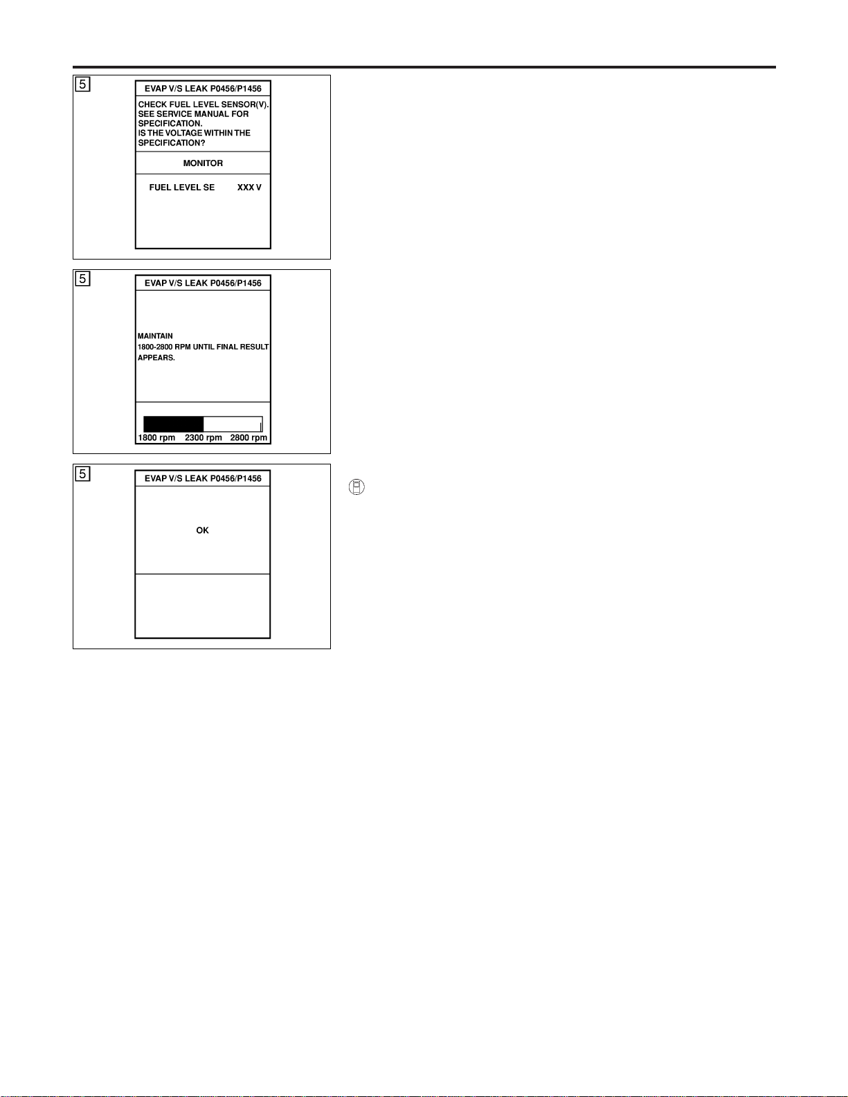
SEC764C
DTC Confirmation Procedure
NFEC0988
SEC765C
SEC766C
CAUTION:
Never remove fuel filler cap during the DTC confirmation pro-
cedure.
NOTE:
I If DTC P0456 is displayed with P0442, perform TROUBLE
DIAGNOSIS FOR DTC P0456 first.
I If “DTC Confirmation Procedure” has been previously
conducted, always turn ignition switch “OFF” and wait at least
10 seconds before conducting the next test.
I After repair, make sure that the hoses and clips are
installed properly.
TESTING CONDITION:
I Open engine hood before conducting following proce-
dure.
I If any of following condition is met just before the DTC
confirmation procedure, leave the vehicle for more than 1
hour.
a) Fuel filler cap is removed.
b) Refilled or drained the fuel.
c) EVAP component parts is/are removed.
I Before performing the following procedure, confirm that
battery voltage is more than 11V at idle.
With CONSULT-II
1) Turn ignition switch “ON” and select “DATA MONITOR” mode
with CONSULT-II.
2) Make sure the following conditions are met.
FUEL LEVEL SE: 1.08 - 0.2V
COOLAN TEMP/S: 0 - 32°C (32 - 90°F)
FUEL T/TMP SE: 0 - 35°C (32 - 95°F)
INT A/TEMP SE: More than 0°C (32°F)
If NG, turn ignition switch “OFF” and leave the vehicle in a cool
place (soak the vehicle) or refilling/draining fuel until the out-
put voltage condition of the “FUELLEVELSE” meets within the
range above and leave the vehicle for more than 1 hour. Then
start from step 1).
3) Turn ignition switch “OFF” and wait at least 5 seconds.
4) Turn ignition switch “ON”.
5) Select “EVP V/S LEAK P0456/P1456” of “EVAPORATIVE
SYSTEM” in “DTC WORK SUPPORT” mode with CONSULT-
II.
Follow the instruction displayed.
6) Make sure that “OK” is displayed.
If “NG” is displayed, refer to “Diagnostic Procedure”, EC-419.
NOTE:
I If the engine speed cannot be maintained within the range
displayed on CONSULT-II screen, go to “Basic
Inspection”, EC-123.
I Make sure that EVAP hoses are connected to EVAP canis-
ter purge volume control solenoid valve properly.
DTC P0456 EVAP CONTROL SYSTEM
DTC Confirmation Procedure
EC-418
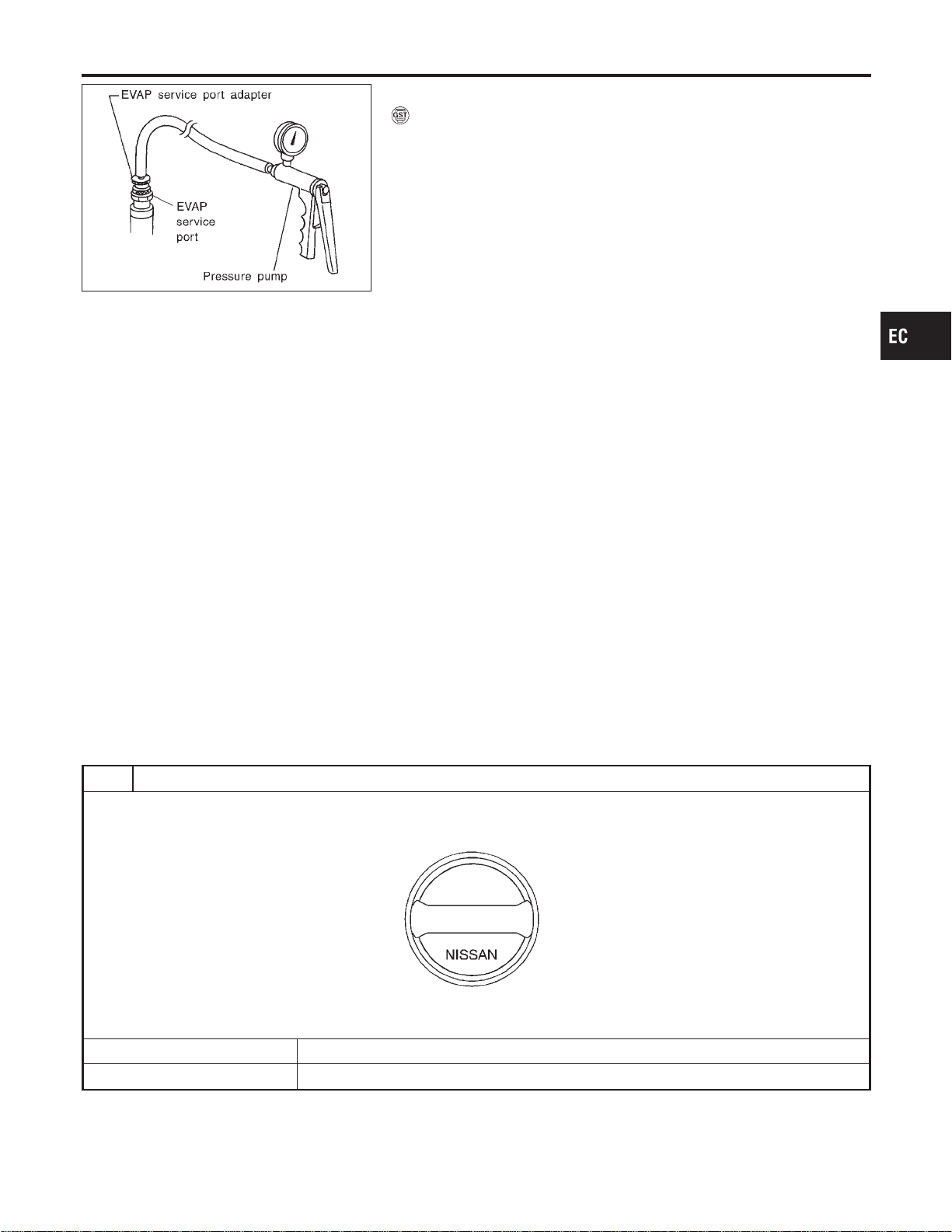
SEF462UA
Overall Function Check
NFEC0989
WITH GST
NFEC0989S01
Use this procedure to check the overall function of the EVAP very
small leak function. During this check, a DTC might not be con-
firmed.
CAUTION:
I Never use compressed air, doing so may damage the
EVAP system.
I Do not start engine.
I Do not exceeded 4.12 kPa (0.042 kg/cm
2
, 0.6 psi).
1) Attach the EVAP service port adapter securely to the EVAP
service port.
2) Set the pressure pump and a hose.
3) Also set a vacuum gauge via 3-way connector and a hose.
4) Turn ignition switch “ON”.
5) Connect GST and select mode 8.
6) Using mode 8 control the EVAP canister vent control valve
(close) and vacuum cut valve bypass valve (open).
7) Apply pressure and make sure the following conditions are
satisfied.
Pressure to be applied: 2.7 kPa (20 mmHg, 0.79 inHg)
Time to be waited after the pressure drawn in to the EVAP
system and the pressure to be dropped: 60 seconds and
the pressure should not be dropped more than 0.4 kPa (3
mmHg, 0.12 inHg)
If NG, go to diagnostic procedure, EC-419.
NOTE:
For more information, refer to GST instruction manual.
Diagnostic Procedure
NFEC0990
1 CHECK FUEL FILLER CAP DESIGN
1. Turn ignition switch “OFF”.
2. Check for genuine NISSAN fuel filler cap design.
SEF915U
OK or NG
OK © GO TO 2.
NG © Replace with genuine NISSAN fuel filler cap.
GI
MA
EM
LC
FE
CL
MT
AT
AX
SU
BR
ST
RS
BT
HA
SC
EL
IDX
DTC P0456 EVAP CONTROL SYSTEM
Overall Function Check
EC-419
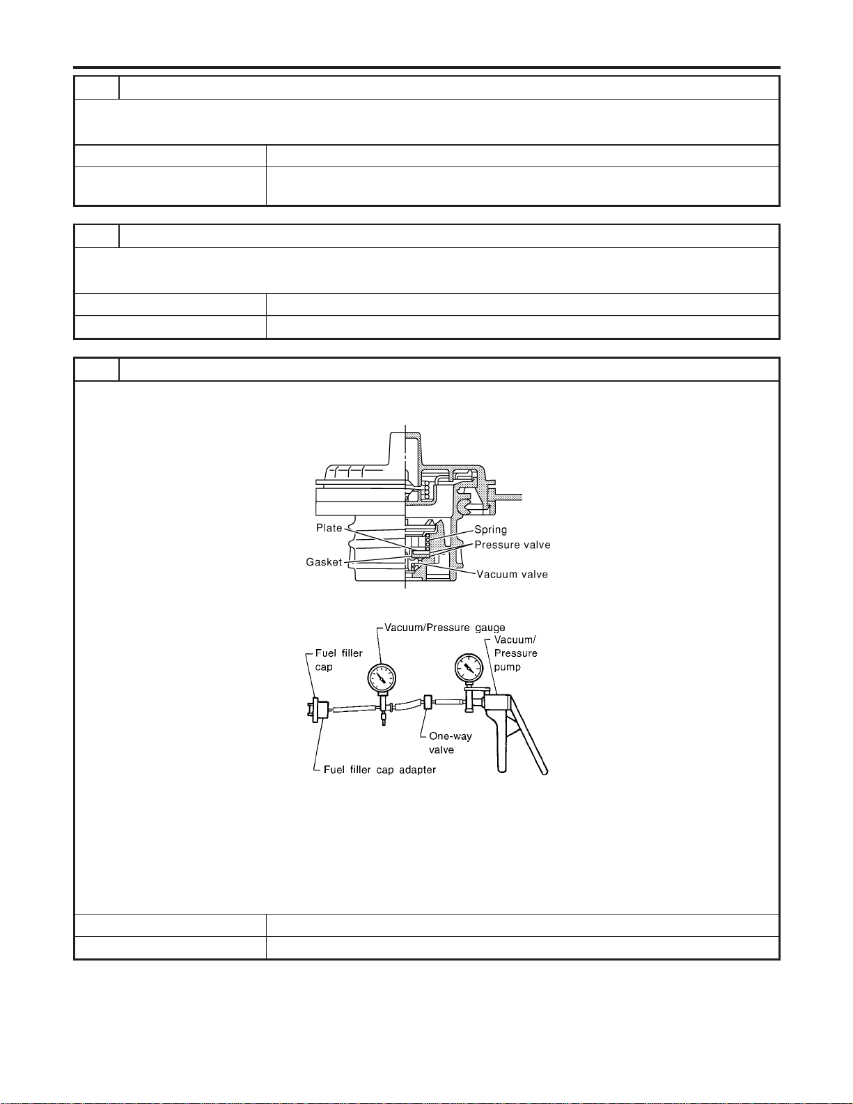
2 CHECK FUEL FILLER CAP INSTALLATION
Check that the cap is tightened properly by rotating the cap clockwise.
OK or NG
OK © GO TO 3.
NG © I Open fuel filler cap, then clean cap and fuel filler neck threads using air blower.
I Retighten until ratcheting sound is heard.
3 CHECK FUEL FILLER CAP FUNCTION
Check for air releasing sound while opening the fuel filler cap.
OK or NG
OK © GO TO 5.
NG © GO TO 4.
4 CHECK FUEL TANK VACUUM RELIEF VALVE
1. Wipe clean valve housing.
2. Check valve opening pressure and vacuum.
SEF445Y
SEF943S
Pressure:
15.3 - 20.0 kPa (0.156 - 0.204 kg/cm
2
, 2.22 - 2.90 psi)
Vacuum:
−6.0 to −3.3 kPa (−0.061 to −0.034 kg/cm
2
, −0.87 to −0.48 psi)
CAUTION:
Use only a genuine fuel filler cap as a replacement. If an incorrect fuel filler cap is used, the MIL may come on.
OK or NG
OK © GO TO 5.
NG © Replace fuel filler cap with a genuine one.
DTC P0456 EVAP CONTROL SYSTEM
Diagnostic Procedure (Cont’d)
EC-420
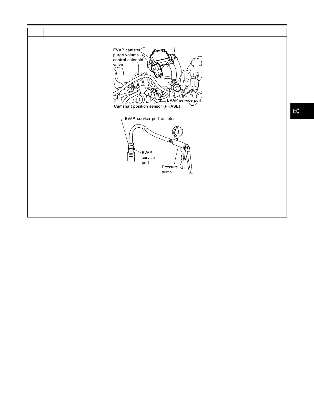
5 INSTALL THE PRESSURE PUMP
To locate the EVAP leak, install EVAP service port adapter and pressure pump to EVAP service port securely.
SEC929C
SEF916U
NOTE:
Improper installation of the EVAP service port adapter to the EVAP service port may cause leaking.
Models with CONSULT-II © GO TO 6.
Models without CON-
SULT-II
© GO TO 7.
GI
MA
EM
LC
FE
CL
MT
AT
AX
SU
BR
ST
RS
BT
HA
SC
EL
IDX
DTC P0456 EVAP CONTROL SYSTEM
Diagnostic Procedure (Cont’d)
EC-421
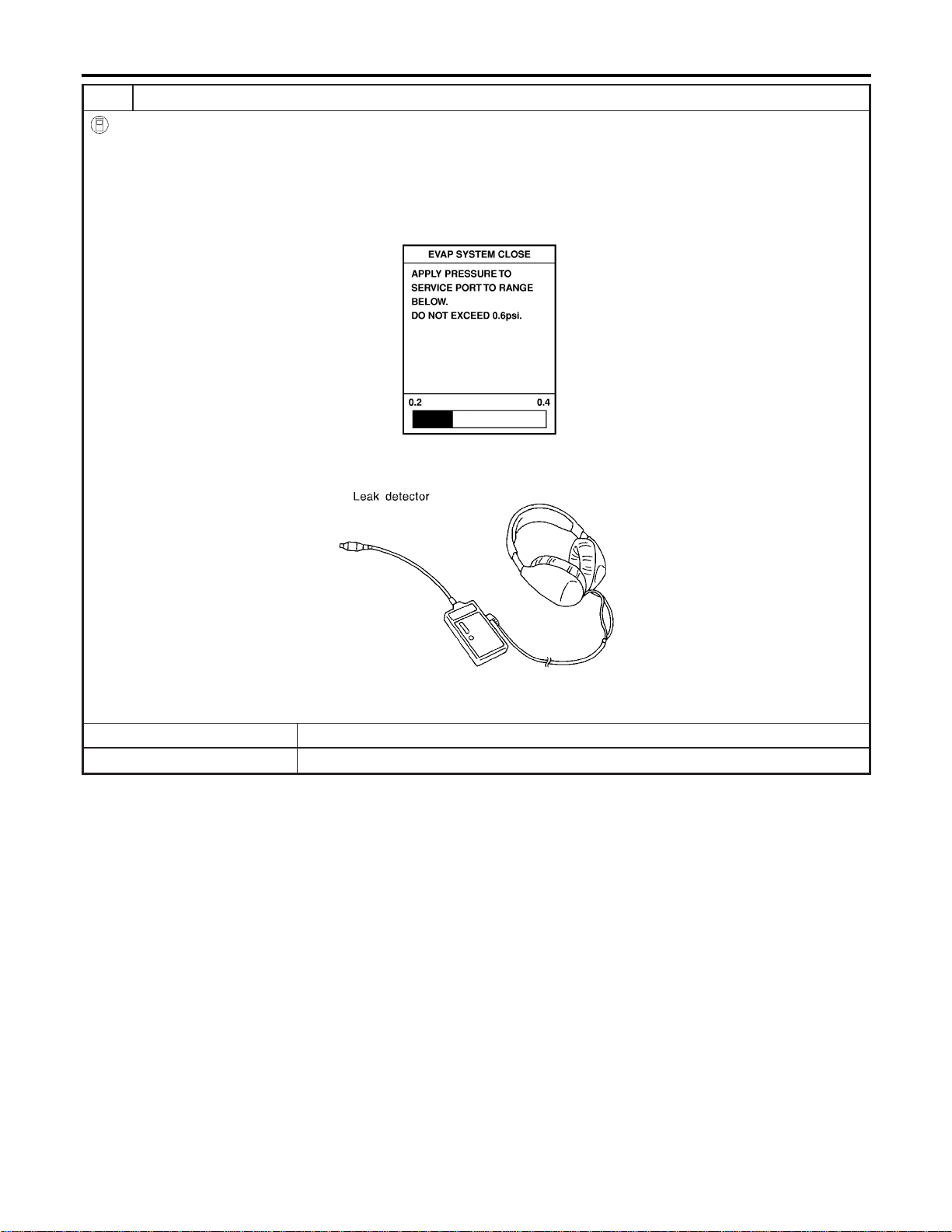
6 CHECK FOR EVAP LEAK
With CONSULT-II
1. Turn ignition switch “ON”.
2. Select “EVAP SYSTEM CLOSE” of “WORK SUPPORT” mode with CONSULT-II.
3. Touch “START” and apply pressure into the EVAP line until the pressure indicator reaches the middle of the bar graph.
NOTE:
I Never use compressed air or a high pressure pump.
I Do not exceed 4.12 kPa (0.042 kg/cm
2
, 0.6 psi) of pressure in the system.
PEF917U
4. Using EVAP leak detector, locate the EVAP leak. For the leak detector, refer to the instruction manual for more details.
Refer to “EVAPORATIVE EMISSION LINE DRAWING”, EC-40.
SEF200U
OK or NG
OK © GO TO 8.
NG © Repair or replace.
DTC P0456 EVAP CONTROL SYSTEM
Diagnostic Procedure (Cont’d)
EC-422
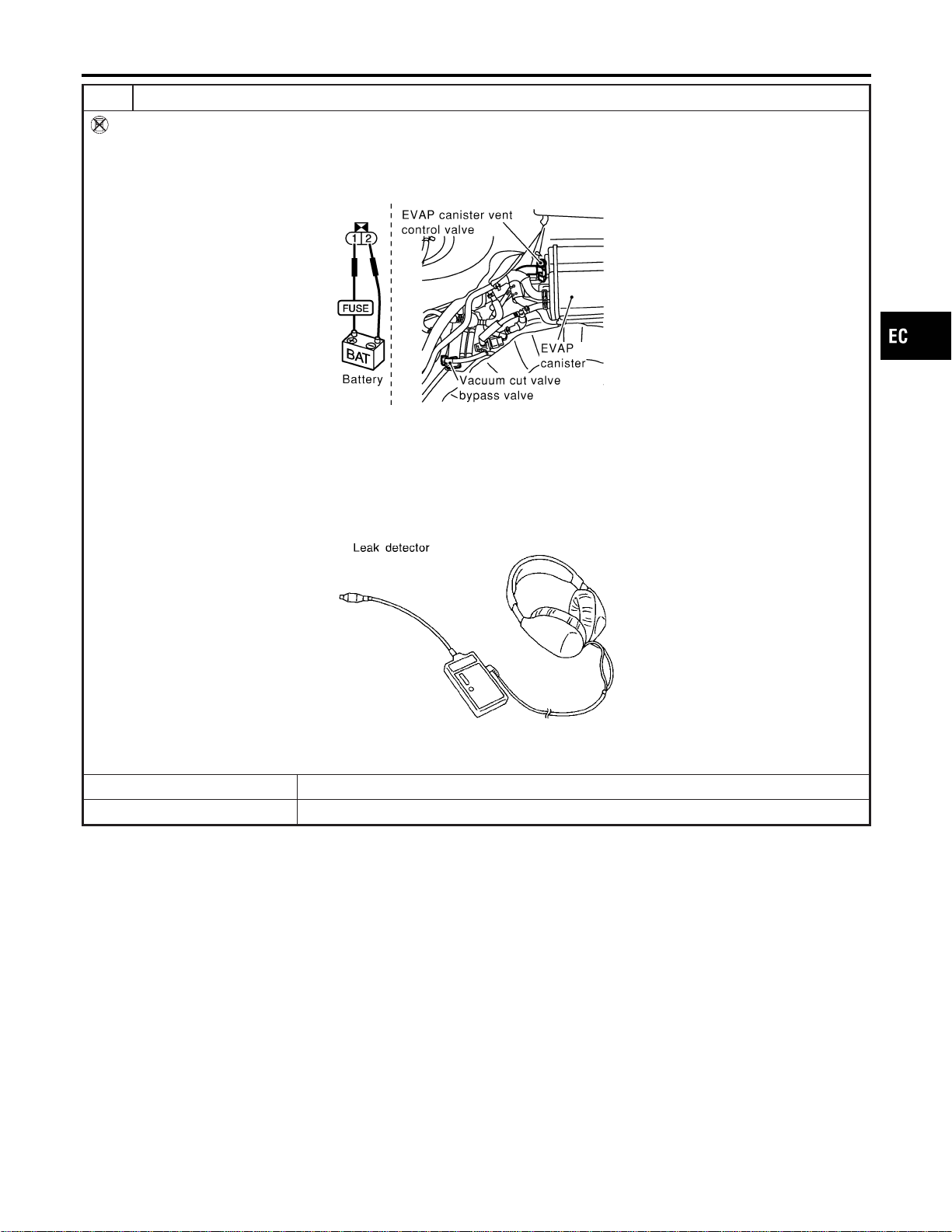
7 CHECK FOR EVAP LEAK
Without CONSULT-II
1. Turn ignition switch “OFF”.
2. Apply 12 volts DC to EVAP canister vent control valve. The valve will close. (Continue to apply 12 volts until the end of
test.)
3. Apply 12 volts DC to vacuum cut valve bypass valve. The valve will open. (Continue to apply 12V until the end of test.)
SEF254X
4. Pressurize the EVAP line using pressure pump with 1.3 to 2.7 kPa (10 to 20 mmHg, 0.39 to 0.79 inHg), then remove
pump and EVAP service port adapter.
NOTE:
I Never use compressed air or a high pressure pump.
I Do not exceed 4.12 kPa (0.042 kg/cm
2
, 0.6 psi) of pressure in the system.
5. Using EVAP leak detector, locate the EVAP leak. For the leak detector, refer to the instruction manual for more details.
Refer to “EVAPORATIVE EMISSION LINE DRAWING”, EC-40.
SEF200U
OK or NG
OK © GO TO 8.
NG © Repair or replace.
GI
MA
EM
LC
FE
CL
MT
AT
AX
SU
BR
ST
RS
BT
HA
SC
EL
IDX
DTC P0456 EVAP CONTROL SYSTEM
Diagnostic Procedure (Cont’d)
EC-423
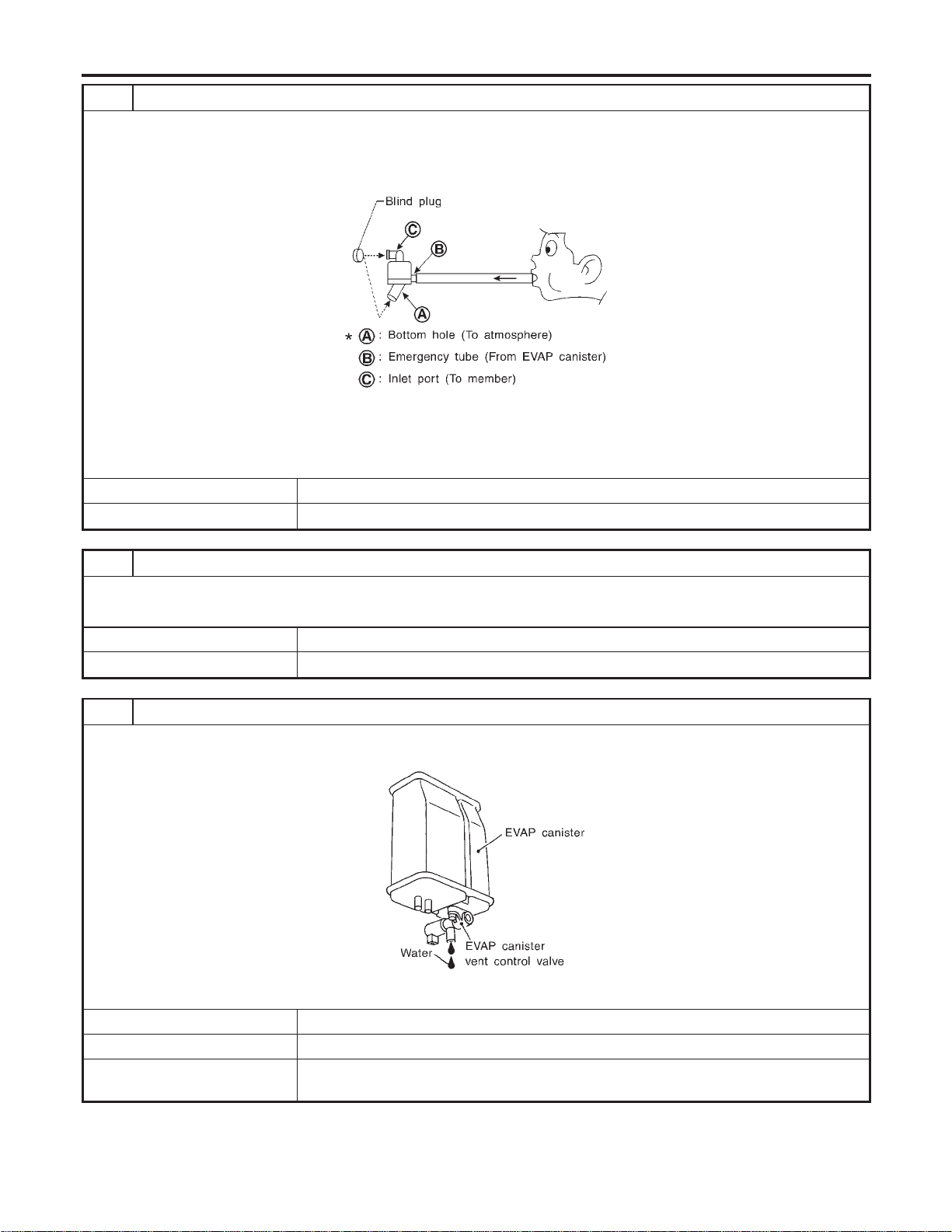
8 CHECK WATER SEPARATOR
1. Check visually for insect nests in the water separator air inlet.
2. Check visually for cracks or flaws in the appearance.
3. Check visually for cracks or flaws in the hose.
4. Check that A and C are not clogged by blowing air into B with A, and then C plugged.
SEF829T
5. In case of NG in items2-4,replace the parts.
NOTE:
Do not disassemble water separator.
OK or NG
OK © GO TO 9.
NG © Replace water separator.
9 CHECK EVAP CANISTER VENT CONTROL VALVE, O-RING AND CIRCUIT
Refer to “DTC Confirmation Procedure”, EC-594.
OK or NG
OK © GO TO 10.
NG © Repair or replace EVAP canister vent control valve and O-ring or harness/connector.
10 CHECK IF EVAP CANISTER SATURATED WITH WATER
1. Remove EVAP canister with EVAP canister vent control valve attached.
2. Does water drain from the EVAP canister?
SEF596U
YesorNo
Yes © GO TO 11.
No (With CONSULT-II) © GO TO 13.
No (Without CONSULT-
II)
© GO TO 14.
DTC P0456 EVAP CONTROL SYSTEM
Diagnostic Procedure (Cont’d)
EC-424
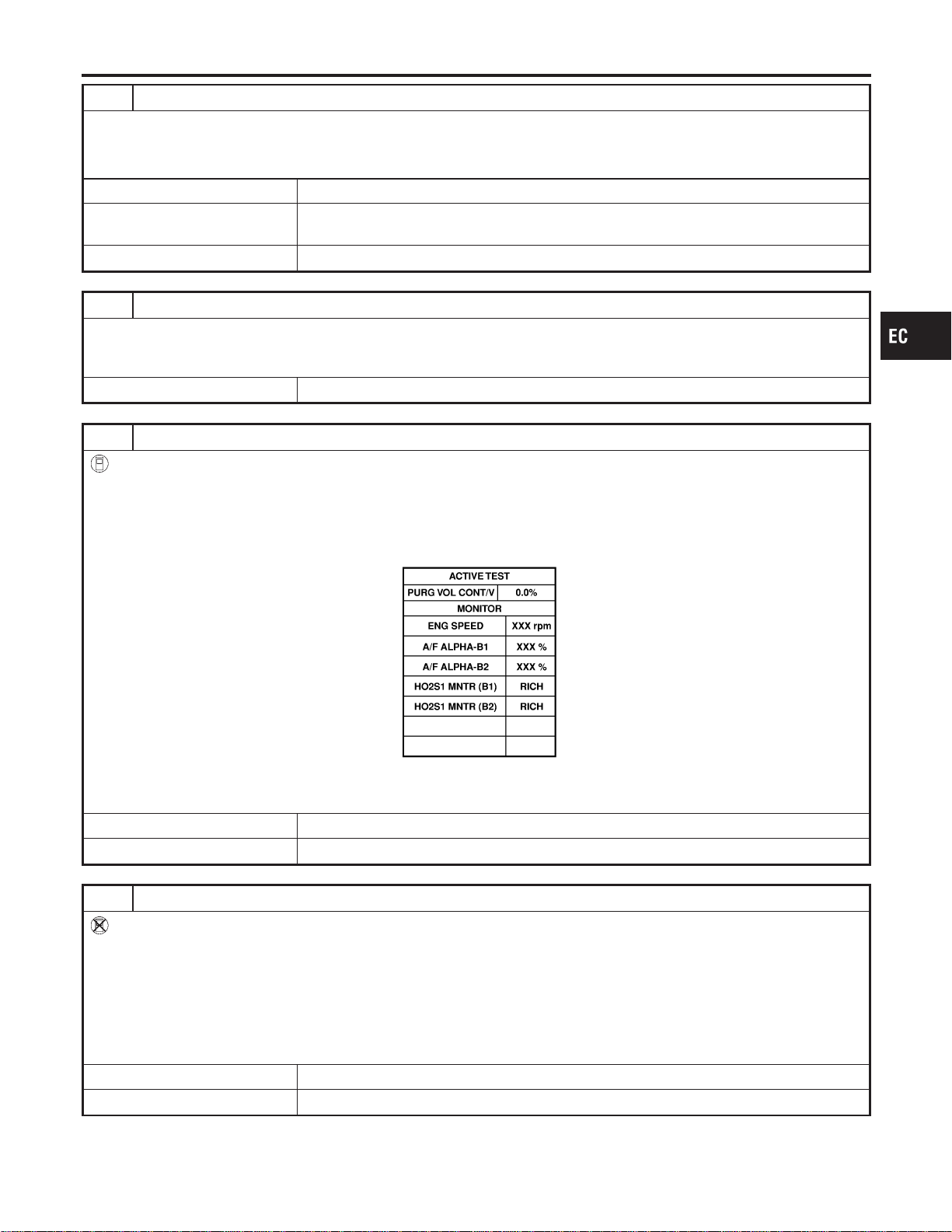
11 CHECK EVAP CANISTER
Weigh the EVAP canister with the EVAP canister vent control valve attached.
The weight should be less than 1.8 kg (4.0 lb).
OK or NG
OK (With CONSULT-II) © GO TO 13.
OK (Without CONSULT-
II)
© GO TO 14.
NG © GO TO 12.
12 DETECT MALFUNCTIONING PART
Check the following.
I EVAP canister for damage
I EVAP hose between EVAP canister and water separator for clogging or poor connection
© Repair hose or replace EVAP canister.
13 CHECK EVAP CANISTER PURGE VOLUME CONTROL SOLENOID VALVE OPERATION
With CONSULT-II
1. Disconnect vacuum hose to EVAP canister purge volume control solenoid valve at EVAP service port.
2. Start engine.
3. Perform “PURG VOL CONT/V” in “ACTIVE TEST” mode.
4. Touch “Qu” on CONSULT-II screen to increase “PURG VOL CONT/V” opening to 100.0%.
5. Check vacuum hose for vacuum when revving engine up to 2,000 rpm.
SEC142D
Vacuum should exist.
OK or NG
OK © GO TO 16.
NG © GO TO 15.
14 CHECK EVAP CANISTER PURGE VOLUME CONTROL SOLENOID VALVE OPERATION
Without CONSULT-II
1. Start engine and warm it up to normal operating temperature.
2. Stop engine.
3. Disconnect vacuum hose to EVAP canister purge volume control solenoid valve at EVAP service port.
4. Start engine and let it idle for at least 80 seconds.
5. Check vacuum hose for vacuum when revving engine up to 2,000 rpm.
Vacuum should exist.
OK or NG
OK © GO TO 17.
NG © GO TO 15.
GI
MA
EM
LC
FE
CL
MT
AT
AX
SU
BR
ST
RS
BT
HA
SC
EL
IDX
DTC P0456 EVAP CONTROL SYSTEM
Diagnostic Procedure (Cont’d)
EC-425
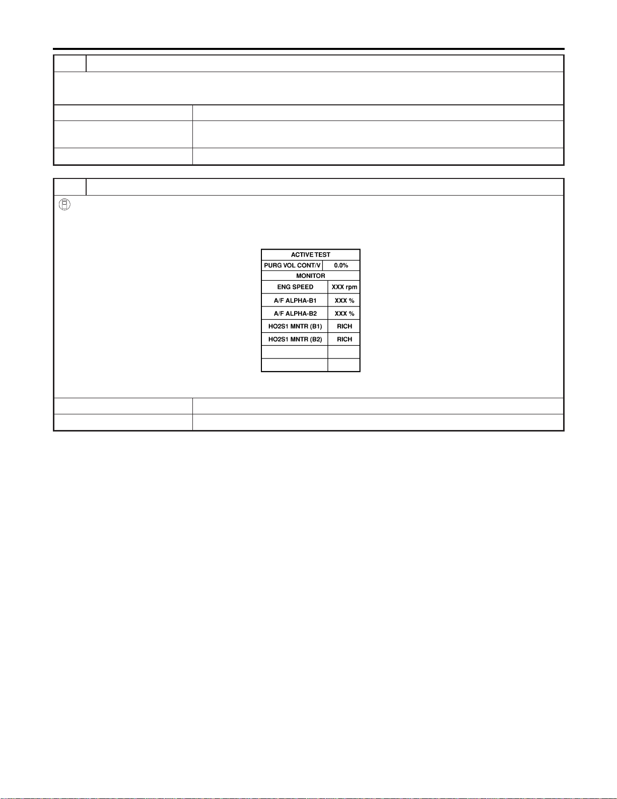
15 CHECK VACUUM HOSE
Check vacuum hoses for clogging or disconnection. Refer to “Vacuum Hose Drawing”, EC-30.
OK or NG
OK (With CONSULT-II) © GO TO 16.
OK (Without CONSULT-
II)
© GO TO 17.
NG © Repair or reconnect the hose.
16 CHECK EVAP CANISTER PURGE VOLUME CONTROL SOLENOID VALVE
With CONSULT-II
1. Start engine.
2. Perform “PURG VOL CONT/V” in “ACTIVE TEST” mode with CONSULT-II. Check that engine speed varies according
to the valve opening.
SEC142D
OK or NG
OK © GO TO 18.
NG © GO TO 17.
DTC P0456 EVAP CONTROL SYSTEM
Diagnostic Procedure (Cont’d)
EC-426
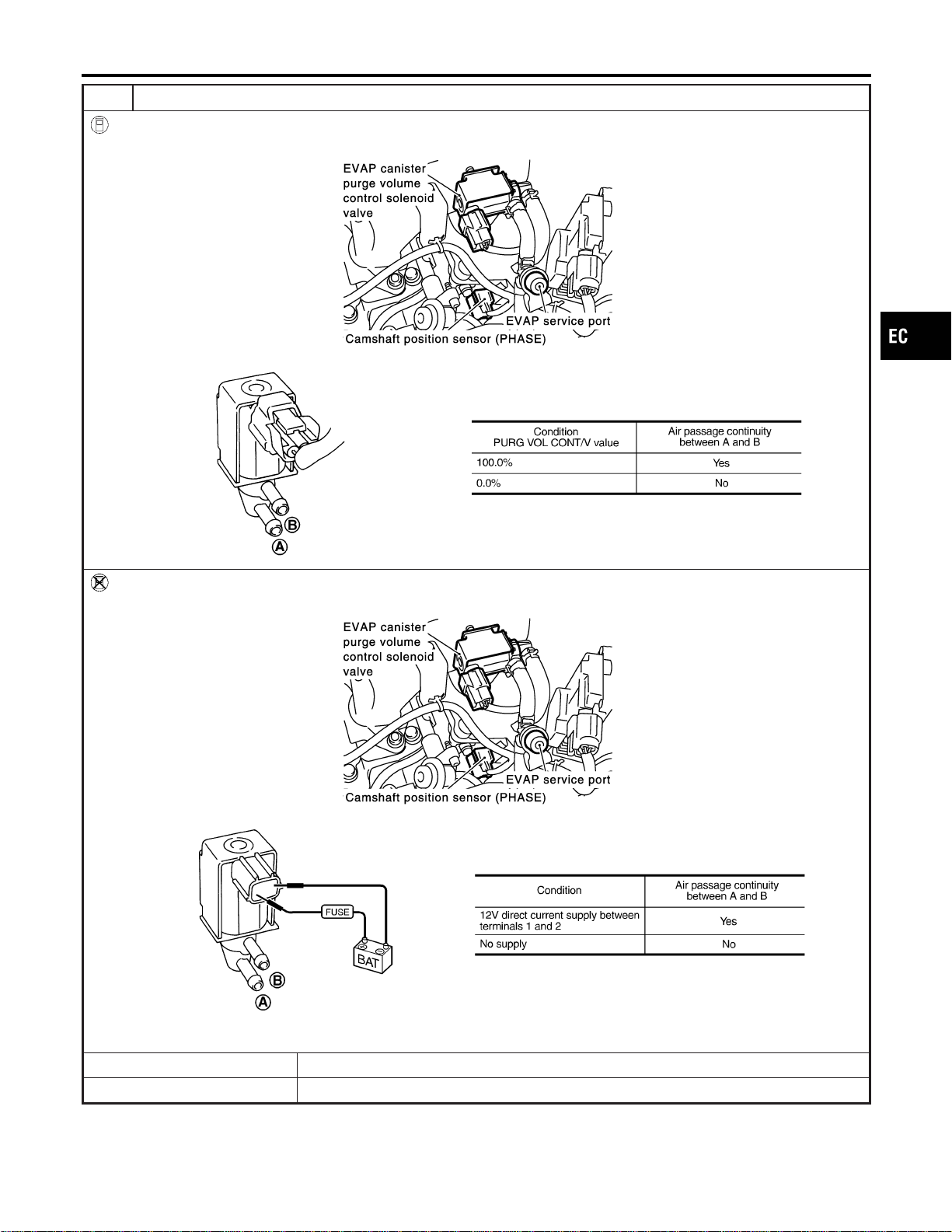
17 CHECK EVAP CANISTER PURGE VOLUME CONTROL SOLENOID VALVE
With CONSULT-II
Check air passage continuity of EVAP canister purge volume control solenoid valve under the following conditions.
SEC929C
SEF334X
Without CONSULT-II
Check air passage continuity of EVAP canister purge volume control solenoid valve under the following conditions.
SEC929C
SEF335X
OK or NG
OK © GO TO 18.
NG © Replace EVAP canister purge volume control solenoid valve.
GI
MA
EM
LC
FE
CL
MT
AT
AX
SU
BR
ST
RS
BT
HA
SC
EL
IDX
DTC P0456 EVAP CONTROL SYSTEM
Diagnostic Procedure (Cont’d)
EC-427
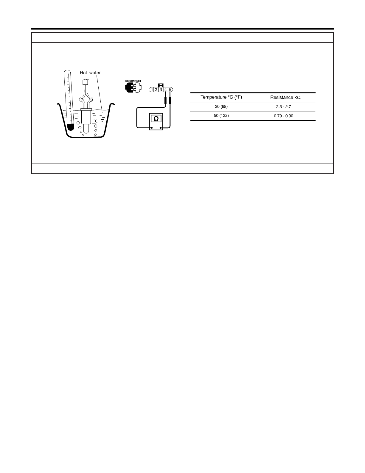
18 CHECK FUEL TANK TEMPERATURE SENSOR
1. Remove fuel level sensor unit.
2. Check resistance between fuel level sensor unit and fuel pump terminals 4 and 5 by heating with hot water or heat gun
as shown in the figure.
SEF587X
OK or NG
OK © GO TO 19.
NG © Replace fuel level sensor unit.
DTC P0456 EVAP CONTROL SYSTEM
Diagnostic Procedure (Cont’d)
EC-428
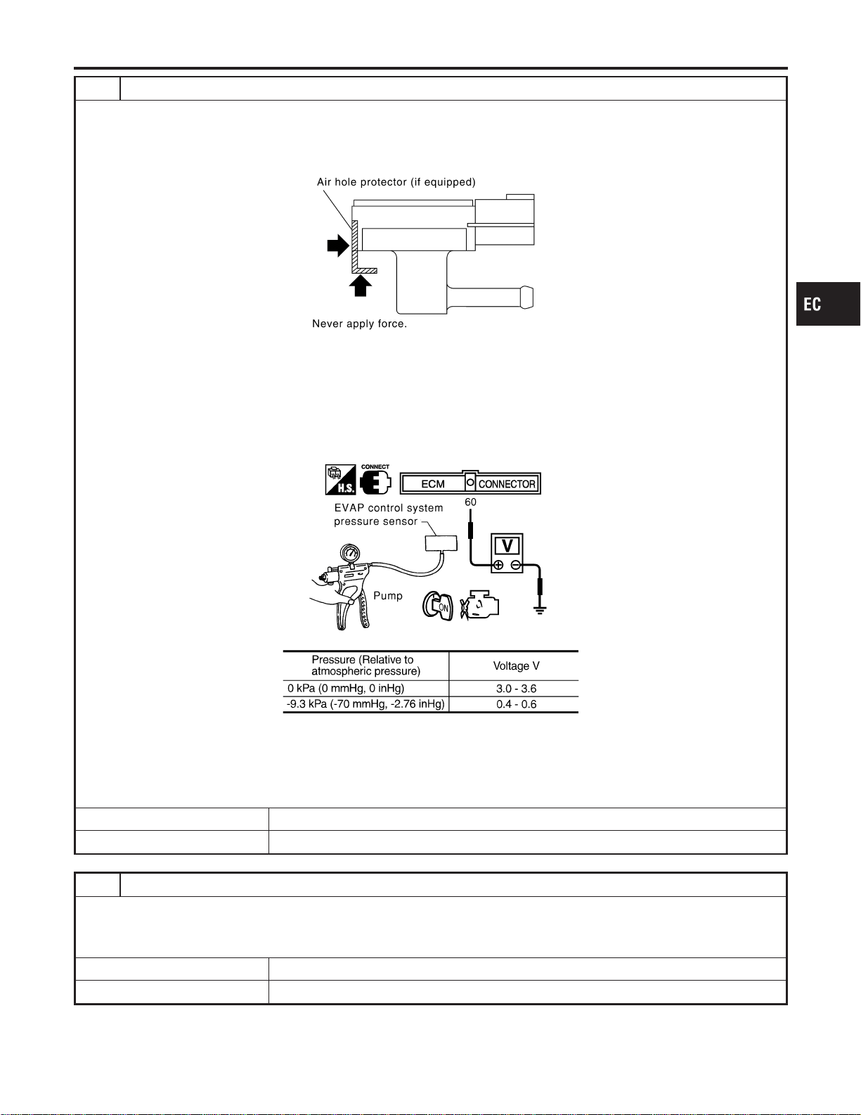
19 CHECK EVAP CONTROL SYSTEM PRESSURE SENSOR
1. Remove EVAP control system pressure sensor with its harness connector connected.
CAUTION:
Never apply force to the air hole protector of the sensor if equipped.
SEF799W
2. Remove hose from EVAP control system pressure sensor.
3. Turn ignition switch “ON”.
4. Use pump to apply vacuum and pressure to EVAP control system pressure sensor as shown in figure.
CAUTION:
I Always calibrate the vacuum pump gauge when using it.
I Do not apply below −20 kPa (−150 mmHg, −5.91 inHg) or over 20 kPa (150 mmHg, 5.91 inHg) of pressure.
5. Check input voltage between ECM terminal 60 and ground.
SEC908C
MTBL1159
CAUTION:
Discard and EVAP control system pressure sensor which has been dropped from a height of more than 0.5 m
(19.7 in) onto a hard surface such as a concrete floor; use a new one.
OK or NG
OK © GO TO 20.
NG © Replace EVAP control system pressure sensor.
20 CHECK EVAP PURGE LINE
Check EVAP purge line (pipe, rubber tube, fuel tank and EVAP canister) for cracks or improper connection.
Refer to “Evaporative Emission System”, EC-36.
OK or NG
OK © GO TO 21.
NG © Repair or reconnect the hose.
GI
MA
EM
LC
FE
CL
MT
AT
AX
SU
BR
ST
RS
BT
HA
SC
EL
IDX
DTC P0456 EVAP CONTROL SYSTEM
Diagnostic Procedure (Cont’d)
EC-429
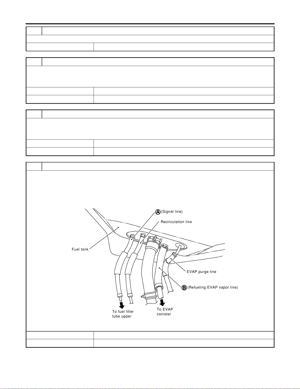
21 CLEAN EVAP PURGE LINE
Clean EVAP purge line (pipe and rubber tube) using air blower.
© GO TO 22.
22 CHECK REFUELING EVAP VAPOR LINE
Check refueling EVAP vapor line between EVAP canister and fuel tank for clogging, kink, looseness and improper connec-
tion. For location, refer to “EVAPORATIVE EMISSION LINE DRAWING”, EC-40.
OK or NG
OK © GO TO 23.
NG © Repair or replace hoses and tubes.
23 CHECK SIGNAL LINE AND RECIRCULATION LINE
Check signal line and recirculation line between filler neck tube and fuel tank for clogging, kink, cracks, looseness and
improper connection.
OK or NG
OK © GO TO 24.
NG © Repair or replace hoses, tubes or filler neck tube.
24 CHECK REFUELING CONTROL VALVE
1. Remove fuel filler cap.
2. Check air continuity between hose ends A and B.
Blow air into hose end B. Air should flow freely into the fuel tank.
3. Blow air into hose end A and check that there is no leakage.
4. Apply pressure to both hose ends A and B [20 kPa (150 mmHg, 5.91 inHg)] using a pressure pump and a suitable
3-way connector. Check that there is no leakage.
SEF830X
OK or NG
OK © GO TO 25.
NG © Replace or refueling control valve with fuel tank.
DTC P0456 EVAP CONTROL SYSTEM
Diagnostic Procedure (Cont’d)
EC-430
25 CHECK FUEL LEVEL SENSOR
Refer to EL-129, “Fuel Level Sensor Unit Check”.
OK or NG
OK © GO TO 26.
NG © Replace fuel level sensor unit.
26 CHECK INTERMITTENT INCIDENT
Refer to “TROUBLE DIAGNOSIS FOR INTERMITTENT INCIDENT”, EC-156.
© INSPECTION END
GI
MA
EM
LC
FE
CL
MT
AT
AX
SU
BR
ST
RS
BT
HA
SC
EL
IDX
DTC P0456 EVAP CONTROL SYSTEM
Diagnostic Procedure (Cont’d)
EC-431
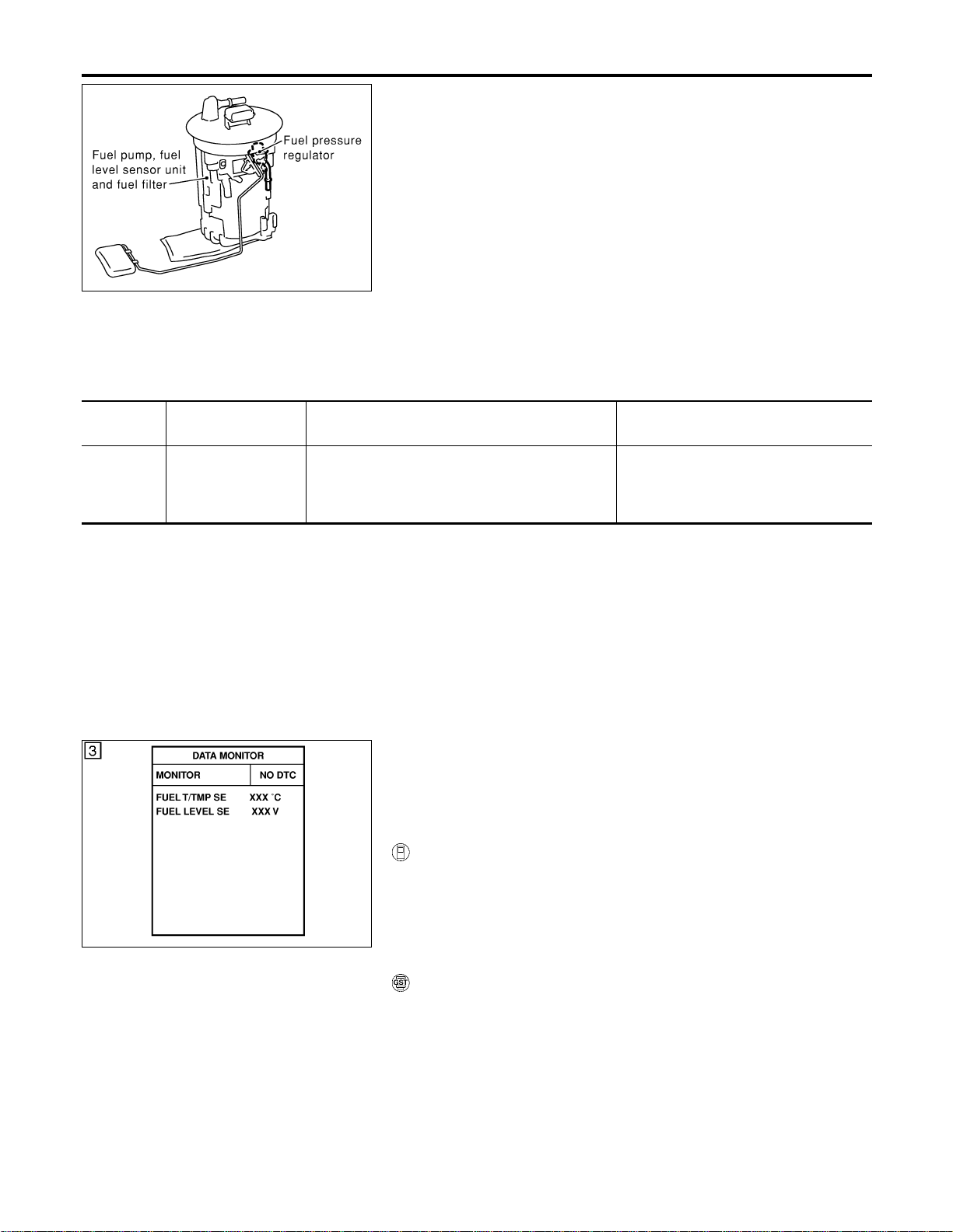
SEC088D
Component Description
NFEC0991
The fuel level sensor is mounted in the fuel level sensor unit. The
sensor detects a fuel level in the fuel tank and transmits a signal
to the ECM.
It consists of two parts, one is mechanical float and the other side
is variable resistor. Fuel level sensor output voltage changes
depending on the movement of the fuel mechanical float.
On Board Diagnostic Logic
NFEC0992
When the vehicle is parked, naturally the fuel level in the fuel tank
is stable. It means that output signal of the fuel level sensor does
not change. If ECM senses sloshing signal from the sensor, fuel
level sensor malfunction is detected.
DTC No.
Trouble diagnosis
name
DTC Detecting Condition Possible Cause
P0460
0460
Fuel level sensor cir-
cuit noise
Even though the vehicle is parked, a signal being
varied is sent from the fuel level sensor to ECM.
I Fuel level sensor circuit
(The fuel level sensor circuit is open
or shorted.)
I Fuel level sensor
SEF195Y
DTC Confirmation Procedure
NFEC0993
NOTE:
If “DTC Confirmation Procedure” has been previously conducted,
always turn ignition switch “OFF” and wait at least 10 seconds
before conducting the next test.
WITH CONSULT-II
NFEC0993S01
1) Turn ignition switch “ON”.
2) Select “DATA MONITOR” mode with CONSULT-II.
3) Start engine and wait maximum of 2 consecutive minutes.
4) If 1st trip DTC is detected, go to “Diagnostic Procedure”,
EC-434.
WITH GST
NFEC0993S02
Follow the procedure “WITH CONSULT-II” above.
DTC P0460 FUEL LEVEL SENSOR
Component Description
EC-432
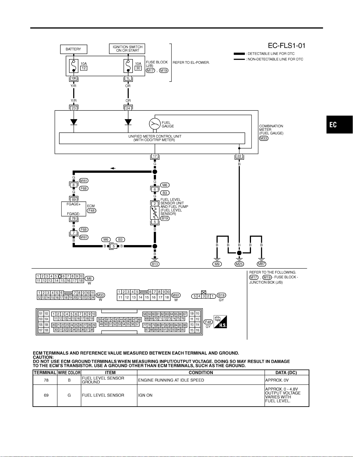
Wiring Diagram
NFEC0994
MEC497D
SEF711YB
GI
MA
EM
LC
FE
CL
MT
AT
AX
SU
BR
ST
RS
BT
HA
SC
EL
IDX
DTC P0460 FUEL LEVEL SENSOR
Wiring Diagram
EC-433
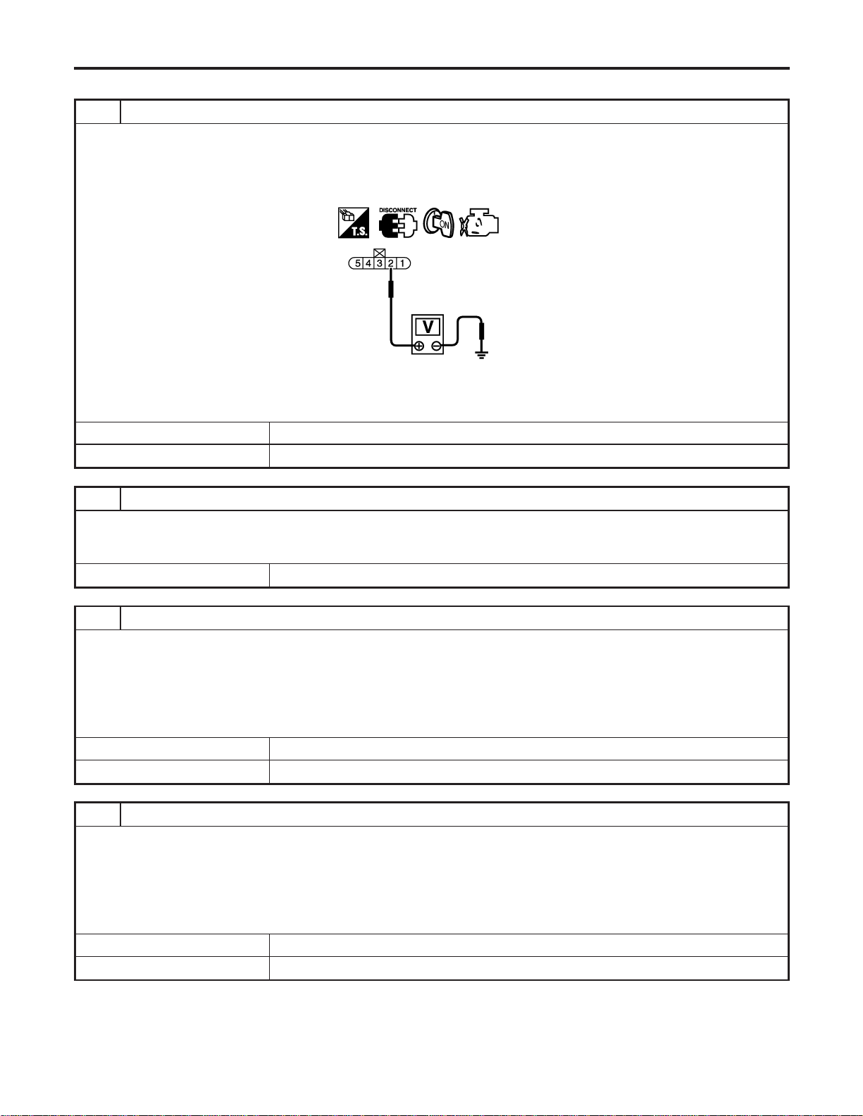
Diagnostic Procedure
=NFEC0995
1 CHECK FUEL LEVEL SENSOR POWER SUPPLY CIRCUIT
1. Turn ignition switch “OFF”.
2. Disconnect fuel level sensor unit and fuel pump harness connector.
3. Turn ignition switch “ON”.
4. Check voltage between fuel level sensor unit and fuel pump terminal 2 and ground with CONSULT-II or a tester.
SEC065D
Voltage: Battery voltage
OK or NG
OK © GO TO 3.
NG © GO TO 2.
2 DETECT MALFUNCTIONING PART
Check the following.
I Harness connectors M6, B3
I Harness for open or short between combination meter and fuel level sensor unit and fuel pump
© Repair or replace harness or connectors.
3 CHECK FUEL LEVEL SENSOR GROUND CIRCUIT FOR OPEN AND SHORT
1. Turn ignition switch “OFF”.
2. Check harness continuity between fuel level sensor unit and fuel pump terminal 5 and body ground. Refer to Wiring
Diagram.
Continuity should exist.
3. Also check harness for short to power.
OK or NG
OK © GO TO 4.
NG © Repair open circuit or short to power in harness or connectors.
4 CHECK FUEL LEVEL SENSOR INPUT SIGNAL CIRCUIT FOR OPEN AND SHORT
1. Disconnect ECM harness connector.
2. Check harness continuity between ECM terminal 69 and fuel level sensor unit and fuel pump terminal 2, ECM terminal
78 and fuel level sensor unit and fuel pump terminal 5. Refer to Wiring Diagram.
Continuity should exist.
3. Also check harness for short to ground and short to power.
OK or NG
OK © GO TO 6.
NG © GO TO 5.
DTC P0460 FUEL LEVEL SENSOR
Diagnostic Procedure
EC-434
5 DETECT MALFUNCTIONING PART
Check the following.
I Harness connectors M161, F68
I Harness connectors M6, B3
I Harness for open or short between ECM and fuel level sensor unit and fuel pump
© Repair open circuit or short to ground or short to power in harness or connectors.
6 CHECK FUEL LEVEL SENSOR
Refer to EL-129, “Fuel Level Sensor Unit Check”.
OK or NG
OK © GO TO 7.
NG © Replace fuel level sensor unit and fuel pump.
7 CHECK INTERMITTENT INCIDENT
Refer to “TROUBLE DIAGNOSIS FOR INTERMITTENT INCIDENT”, EC-156.
© INSPECTION END
GI
MA
EM
LC
FE
CL
MT
AT
AX
SU
BR
ST
RS
BT
HA
SC
EL
IDX
DTC P0460 FUEL LEVEL SENSOR
Diagnostic Procedure (Cont’d)
EC-435
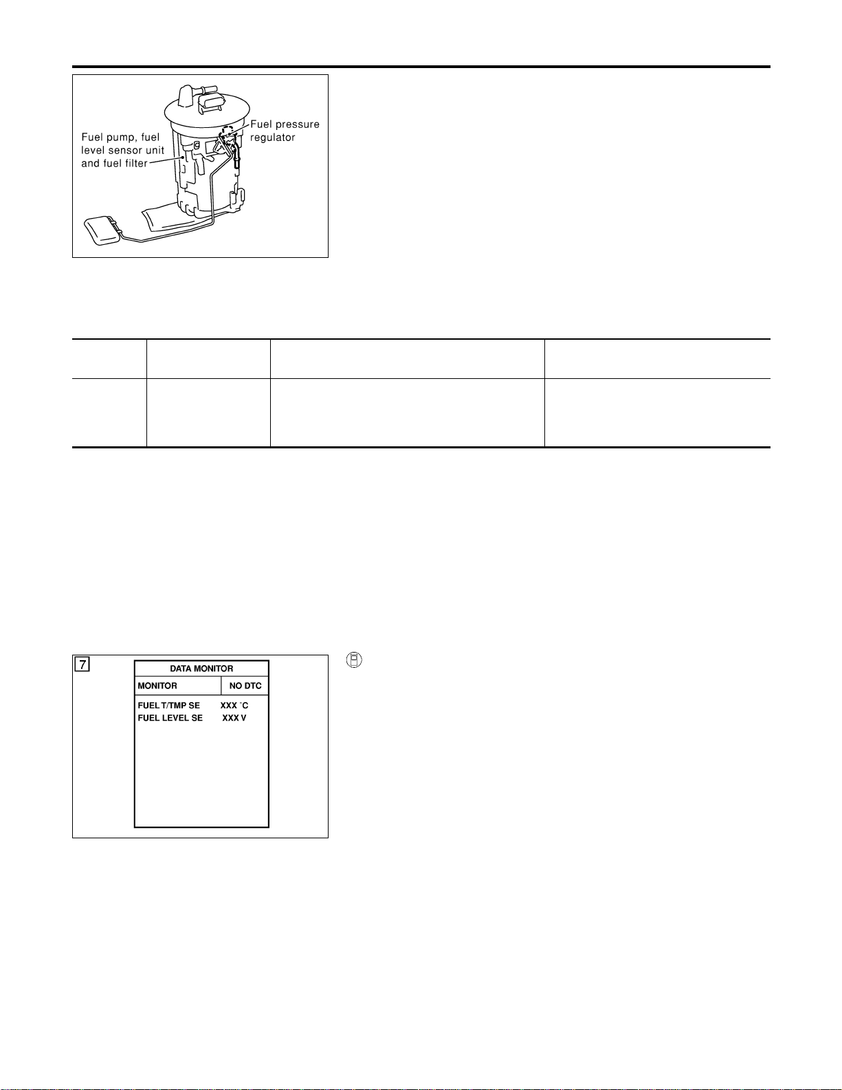
SEC088D
Component Description
=NFEC0996
The fuel level sensor is mounted in the fuel level sensor unit. The
sensor detects a fuel level in the fuel tank and transmits a signal
to the ECM.
It consists of two parts, one is mechanical float and the other side
is variable resistor. Fuel level sensor output voltage changes
depending on the movement of the fuel mechanical float.
On Board Diagnostic Logic
NFEC0997
Driving long distances naturally affect fuel gauge level.
This diagnosis detects the fuel gauge malfunction of the gauge not
moving even after a long distance has been driven.
DTC No.
Trouble diagnosis
name
DTC Detecting Condition Possible Cause
P0461
0461
Fuel level sensor cir-
cuit range/
performance
The output signal of the fuel level sensor does not
change within the specified range even though the
vehicle has been driven a long distance.
I Harness or connectors
(The level sensor circuit is open or
shorted.)
I Fuel level sensor
Overall Function Check
NFEC0998
Use this procedure to check the overall function of the fuel level
sensor function. During this check, a 1st trip DTC might not be
confirmed.
WARNING:
When performing following procedure, be sure to observe the
handling of the fuel. Refer to FE-4, “Fuel Tank”.
TESTING CONDITION:
Before starting overall function check, preparation of draining
fuel and refilling fuel is required.
SEF195Y
WITH CONSULT-II
NFEC0998S01
NOTE:
Start from step 11, if it is possible to confirm that the fuel
cannot be drained by 30 (7-7/8 US gal, 6-5/8 Imp gal) in
advance.
1) Prepare a fuel container and a spare hose.
2) Release fuel pressure from fuel line, refer to “Fuel Pressure
Release”, EC-56.
3) Remove the fuel feed hose on the fuel level sensor unit.
4) Connect a spare fuel hose where the fuel feed hose was
removed.
5) Turn ignition switch “OFF” and wait at least 10 seconds then
turn “ON”.
6) Select “FUEL LEVEL SE” in “DATA MONITOR” mode with
CONSULT-II.
7) Check “FUEL LEVEL SE” output voltage and note it.
8) Select “FUEL PUMP” in “ACTIVE TEST” mode with CON-
SULT-II.
9) Touch “ON” and drain fuel approximately 30 (7-7/8 US gal,
6-5/8 Imp gal) and stop it.
10) Fill fuel into the fuel tank for 30 (7-7/8 US gal, 6-5/8 Imp gal).
11) Check “FUEL LEVEL SE” output voltage and note it.
DTC P0461 FUEL LEVEL SENSOR
Component Description
EC-436
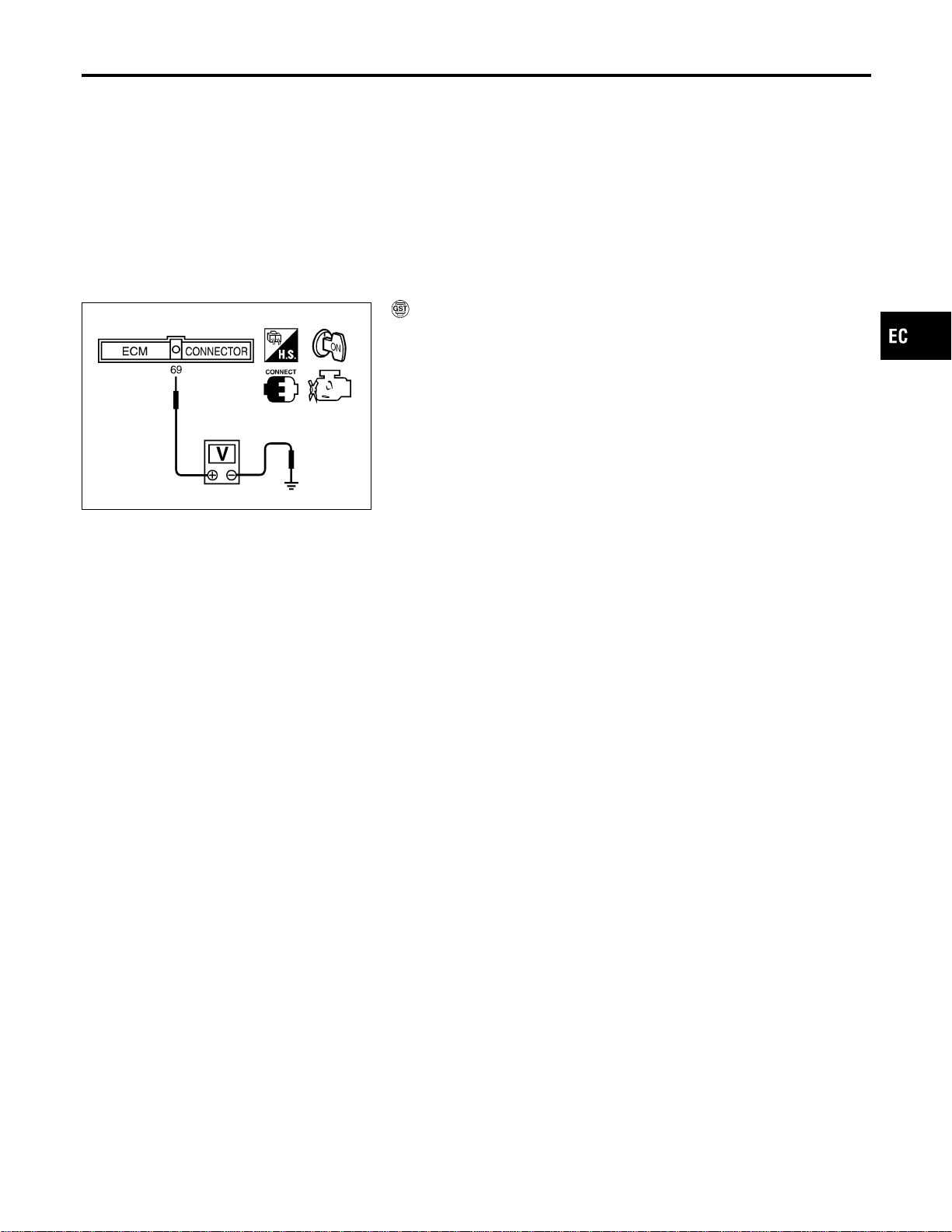
12) Check “FUEL LEVEL SE” output voltage and confirm whether
the voltage changes more than 0.03V during step 7 to 11.
If NG, check the fuel level sensor, refer to EL-129, “FUEL
LEVEL SENSOR UNIT CHECK”.
SEC910C
WITH GST
NFEC0998S02
NOTE:
Start from step 11, if it is possible to confirm that the fuel
cannot be drained by 30 (7-7/8 US gal, 6-5/8 Imp gal) in
advance.
1) Prepare a fuel container and a spare hose.
2) Release fuel pressure from fuel line, refer to “Fuel Pressure
Release”, EC-56.
3) Remove the fuel feed hose on the fuel level sensor unit.
4) Connect a spare fuel hose where the fuel feed hose was
removed.
5) Turn ignition switch “OFF”.
6) Set voltmeters probe between ECM terminal 69 (fuel level
sensor signal) and ground.
7) Turn ignition switch “ON”.
8) Check voltage between ECM terminal 69 and ground and note
it.
9) Drain fuel by 30 (7-7/8 US gal, 6-5/8 Imp gal) from the fuel
tank using proper equipment.
10) Fill fuel into the fuel tank for 30 (7-7/8 US gal, 6-5/8 Imp gal).
11) Confirm that the voltage between ECM terminal 69 and ground
changes more than 0.03V during step8-10.
If NG, check component of fuel level sensor, refer to EL-129,
“FUEL LEVEL SENSOR UNIT CHECK”.
GI
MA
EM
LC
FE
CL
MT
AT
AX
SU
BR
ST
RS
BT
HA
SC
EL
IDX
DTC P0461 FUEL LEVEL SENSOR
Overall Function Check (Cont’d)
EC-437
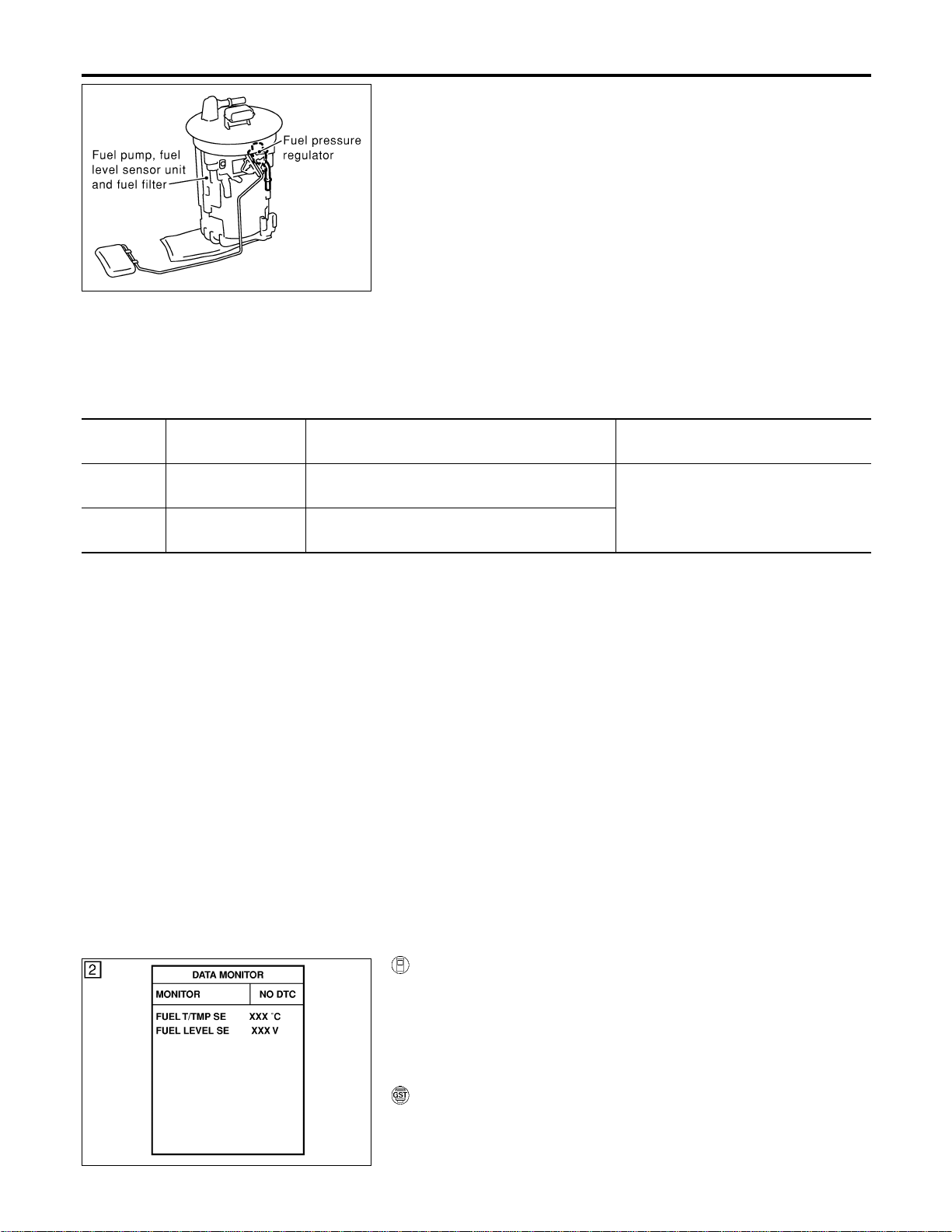
SEC088D
Component Description
NFEC0999
The fuel level sensor is mounted in the fuel level sensor unit. The
sensor detects a fuel level in the fuel tank and transmits a signal
to the ECM.
It consists of two parts, one is mechanical float and the other side
is variable resistor. Fuel level sensor output voltage changes
depending on the movement of the fuel mechanical float.
On Board Diagnostic Logic
NFEC1000
ECM receives two signals from the fuel level sensor circuit.
One is fuel level sensor power supply circuit, and the other is fuel
level sensor ground circuit.
This diagnosis indicates the former, to detect open or short circuit
malfunction.
DTC No.
Trouble diagnosis
name
DTC Detecting Condition Possible Cause
P0462
0462
Fuel level sensor cir-
cuit low input
An excessively low voltage is sent from the sensor
is sent to ECM.
I Harness or connectors
(The sensor circuit is open or
shorted.)
I Fuel level sensor
P0463
0463
Fuel level sensor cir-
cuit high input
An excessively high voltage is sent from the sen-
sor is sent to ECM.
DTC Confirmation Procedure
NFEC1001
NOTE:
If “DTC Confirmation Procedure” has been previously conducted,
always turn ignition switch “OFF” and wait at least 10 seconds
before conducting the next test.
TESTING CONDITION:
Before performing the following procedure, confirm that bat-
tery voltage is more than 11V at ignition switch “ON”.
SEF195Y
WITH CONSULT-II
NFEC1001S01
1) Turn ignition switch “ON”.
2) Select “DATA MONITOR” mode with CONSULT-II.
3) Wait at least 5 seconds.
4) If 1st trip DTC is detected, go to “Diagnostic Procedure”,
EC-440.
WITH GST
NFEC1001S02
Follow the procedure “WITH CONSULT-II” above.
DTC P0462, P0463 FUEL LEVEL SENSOR
Component Description
EC-438
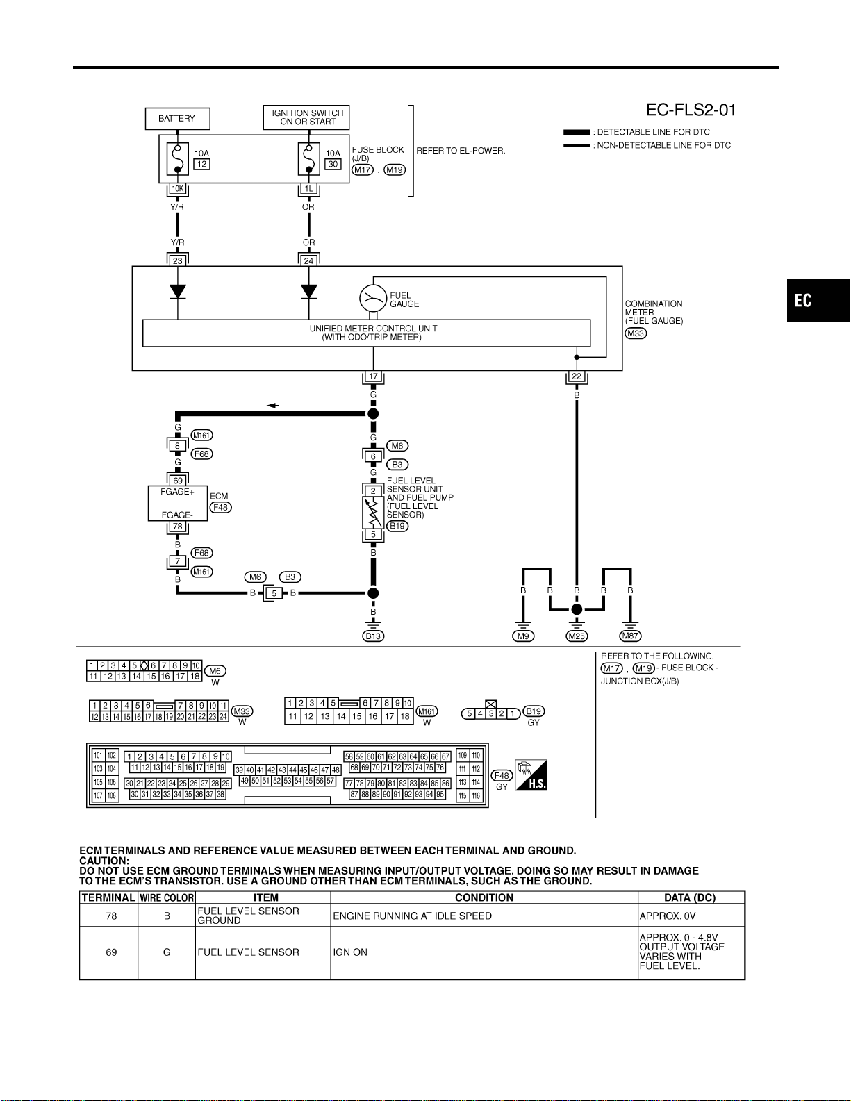
Wiring Diagram
NFEC1002
MEC498D
SEF711YB
GI
MA
EM
LC
FE
CL
MT
AT
AX
SU
BR
ST
RS
BT
HA
SC
EL
IDX
DTC P0462, P0463 FUEL LEVEL SENSOR
Wiring Diagram
EC-439
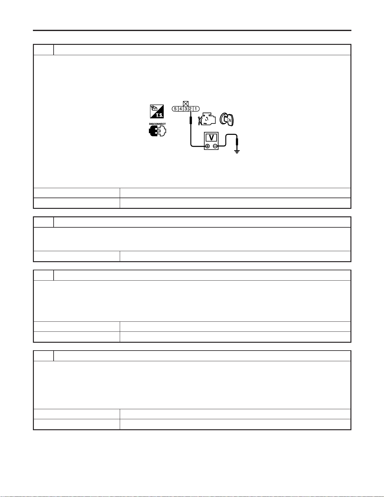
Diagnostic Procedure
=NFEC1003
1 CHECK FUEL LEVEL SENSOR POWER SUPPLY CIRCUIT
1. Turn ignition switch “OFF”.
2. Disconnect fuel level sensor unit and fuel pump harness connector.
3. Turn ignition switch “ON”.
4. Check voltage between fuel level sensor unit and fuel pump terminal 2 and ground with CONSULT-II or tester.
SEC220D
Voltage: Battery voltage
OK or NG
OK © GO TO 3.
NG © GO TO 2.
2 DETECT MALFUNCTIONING PART
Check the following.
I Harness connectors M6, B3
I Harness for open or short between combination meter and fuel level sensor unit
© Repair or replace harness or connectors.
3 CHECK FUEL LEVEL SENSOR GROUND CIRCUIT FOR OPEN AND SHORT
1. Turn ignition switch “OFF”.
2. Check harness continuity between fuel level sensor unit terminal 5 and body ground. Refer to Wiring Diagram.
Continuity should exist.
3. Also check harness for short to power.
OK or NG
OK © GO TO 4.
NG © Repair open circuit or short to power in harness or connectors.
4 CHECK FUEL LEVEL SENSOR INPUT SIGNAL CIRCUIT FOR OPEN AND SHORT
1. Disconnect ECM harness connector.
2. Check harness continuity between ECM terminal 69 and fuel level sensor and fuel pump terminal 2. Refer to Wiring
Diagram.
Continuity should exist.
3. Also check harness for short to power.
OK or NG
OK © GO TO 6.
NG © GO TO 5.
DTC P0462, P0463 FUEL LEVEL SENSOR
Diagnostic Procedure
EC-440
5 DETECT MALFUNCTIONING PART
Check the following.
I Harness connectors F68, M161
I Harness connectors M6, B3
I Harness for open between ECM and fuel level sensor
© Repair open circuit or short to power in harness on connectors.
6 CHECK FUEL LEVEL SENSOR
Refer to EL-129, “Fuel Level Sensor Unit Check”.
OK or NG
OK © GO TO 7.
NG © Replace fuel level sensor unit.
7 CHECK INTERMITTENT INCIDENT
Refer to “TROUBLE DIAGNOSIS FOR INTERMITTENT INCIDENT”, EC-156.
© INSPECTION END
GI
MA
EM
LC
FE
CL
MT
AT
AX
SU
BR
ST
RS
BT
HA
SC
EL
IDX
DTC P0462, P0463 FUEL LEVEL SENSOR
Diagnostic Procedure (Cont’d)
EC-441
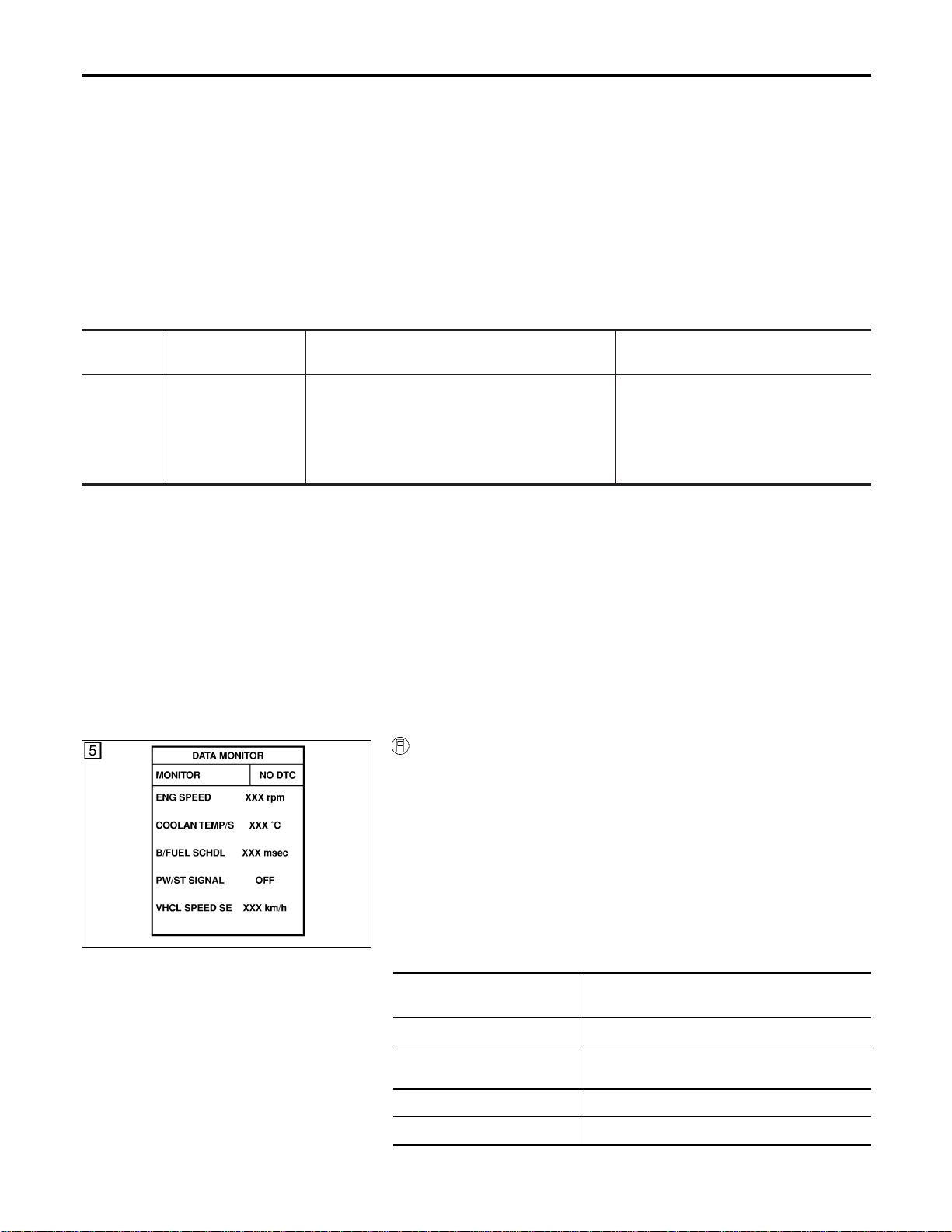
Component Description
=NFEC1004
The vehicle speed sensor signal is sent from ABS actuator and
electric unit or ABS/TCS control unit to combination meter. The
combination meter then sends a signal to the ECM.
On Board Diagnosis Logic
NFEC1006
DTC No.
Trouble diagnosis
name
DTC Detecting Condition Possible Cause
P0500
0500
Vehicle speed sensor The almost 0 km/h (0 MPH) signal from vehicle
speed sensor signal is sent to ECM even when
vehicle is being driven.
I Harness or connector
(The vehicle speed sensor signal cir-
cuit is open or shorted.)
I ABS actuator and electric unit or
ABS/TCS control unit
I Combination meter
DTC Confirmation Procedure
NFEC1007
CAUTION:
Always drive vehicle at a safe speed.
NOTE:
If “DTC Confirmation Procedure” has been previously conducted,
always turn ignition switch “OFF” and wait at least 10 seconds
before conducting the next test.
TESTING CONDITION:
Steps 1 and 2 may be conducted with the drive wheels lifted
in the shop or by driving the vehicle. If a road test is expected
to be easier, it is unnecessary to lift the vehicle.
SEF196Y
WITH CONSULT-II
NFEC1007S01
1) Start engine.
2) Read “VHCL SPEED SE” in “DATA MONITOR” mode with
CONSULT-II. The vehicle speed on CONSULT-II should
exceed 10 km/h (6 MPH) when rotating wheels with suitable
gear position.
If NG, go to “Diagnostic Procedure”, EC-445.
If OK, go to following step.
3) Select “DATA MONITOR” mode with CONSULT-II.
4) Warm engine up to normal operating temperature.
5) Maintain the following conditions for at least 10 consecutive
seconds.
ENG SPEED More than 1,800 rpm (A/T)
More than 2,000 rpm (M/T)
COOLAN TEMP/S More than 70°C (158°F)
B/FUEL SCHDL 5.5 - 14.0 msec (A/T)
6.0 - 14.0 msec (M/T)
Selector lever Suitable position
PW/ST SIGNAL OFF
DTC P0500 VSS
Component Description
EC-442

6) If 1st trip DTC is detected, go to “Diagnostic Procedure”,
EC-445.
Overall Function Check
NFEC1008
Use this procedure to check the overall function of the vehicle
speed sensor signal circuit. During this check, a 1st trip DTC might
not be confirmed.
WITH GST
NFEC1008S01
1) Lift up drive wheels.
2) Start engine.
3) Read vehicle speed sensor signal in “MODE 1” with GST.
The vehicle speed sensor signal on GST should be able to
exceed 10 km/h (6 MPH) when rotating wheels with suitable
gear position.
4) If NG, go to “Diagnostic Procedure”, EC-445.
GI
MA
EM
LC
FE
CL
MT
AT
AX
SU
BR
ST
RS
BT
HA
SC
EL
IDX
DTC P0500 VSS
DTC Confirmation Procedure (Cont’d)
EC-443
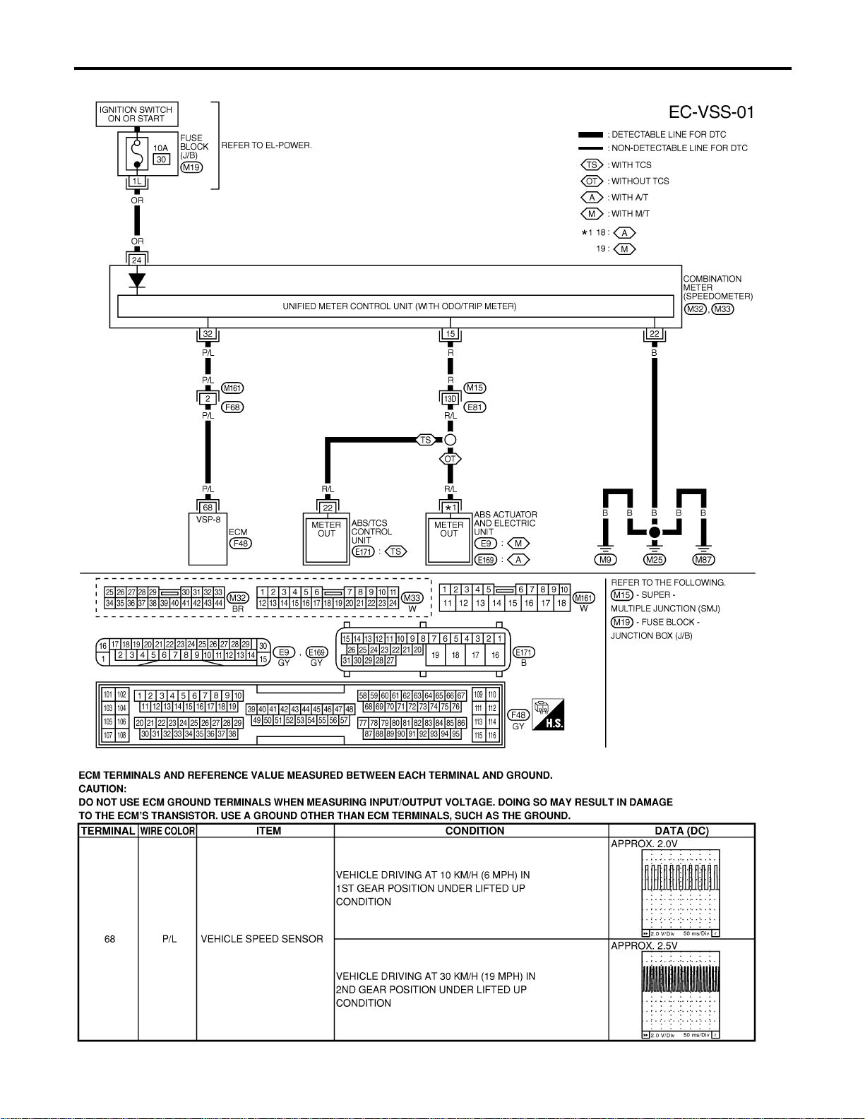
Wiring Diagram
=NFEC1009
MEC499D
SEC045D
DTC P0500 VSS
Wiring Diagram
EC-444

Diagnostic Procedure
NFEC1010
1 CHECK VEHICLE SPEED SENSOR INPUT SIGNAL CIRCUIT FOR OPEN AND SHORT
1. Turn ignition switch “OFF”.
2. Disconnect ECM harness connector and combination meter harness connector M32.
3. Check harness continuity between ECM terminal 68 and combination meter terminal 32.
Refer to Wiring Diagram.
Continuity should exist.
4. Also check harness for short to power.
OK or NG
OK © GO TO 3.
NG © GO TO 2.
2 DETECT MALFUNCTIONING PART
Check the following.
I Harness connectors M161, F68
I Harness for open or short between ECM and combination meter
© Repair open circuit or short to ground or short to power in harness or connectors.
3 CHECK COMBINATION METER FUNCTION
Make sure that speedometer functions properly.
OK or NG
OK © GO TO 5.
NG © GO TO 4.
4 CHECK COMBINATION METER CIRCUIT FOR OPEN AND SHORT
Check the following.
I Harness connectors M15, E81
I Harness for open or short between combination meter and ABS actuator and electric unit or ABS/TCS control unit
I Harness for open between combination meter and ground
OK or NG
OK © Check combination meter and ABS actuator and electric unit or ABS/TCS control unit.
Refer to EL section.
NG © Repair open circuit or short to ground or short to power in harness or connectors.
5 CHECK INTERMITTENT INCIDENT
Refer to “TROUBLE DIAGNOSIS FOR INTERMITTENT INCIDENT”, EC-156.
© INSPECTION END
GI
MA
EM
LC
FE
CL
MT
AT
AX
SU
BR
ST
RS
BT
HA
SC
EL
IDX
DTC P0500 VSS
Diagnostic Procedure
EC-445
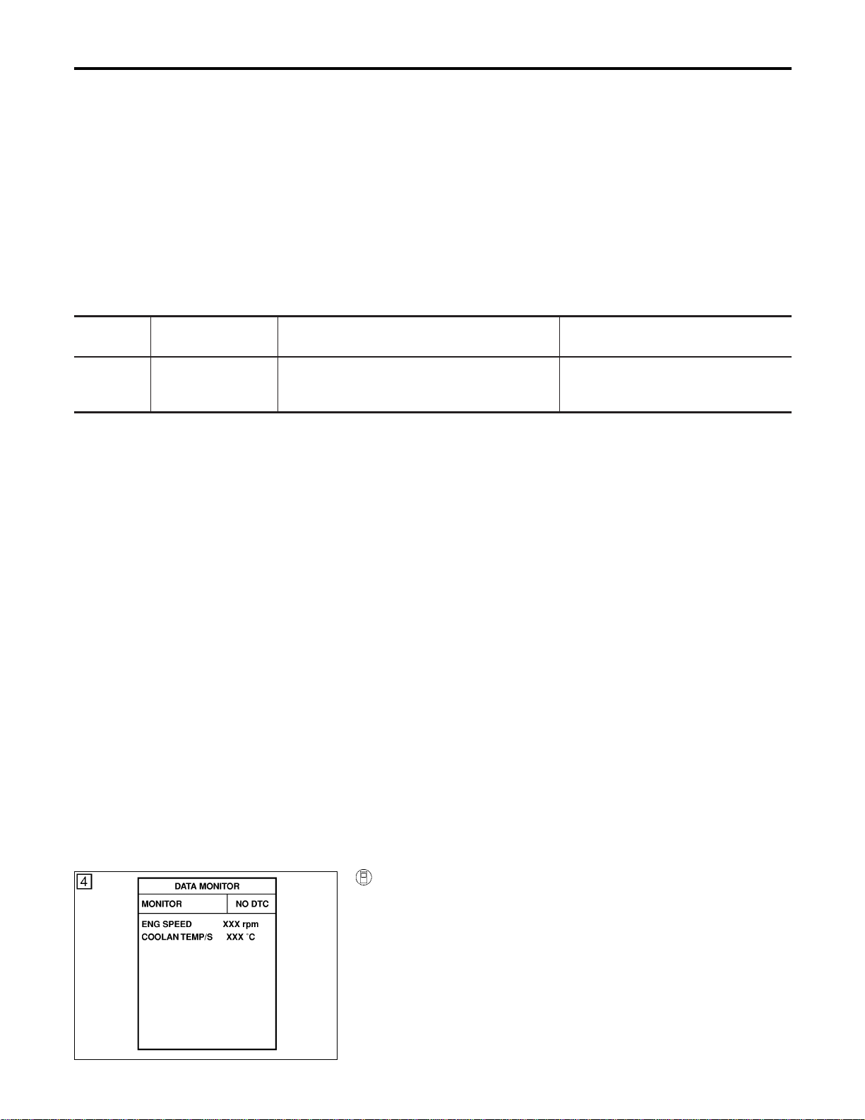
Description
NFEC0787
NOTE:
If DTC P0506 is displayed with other DTC, first perform the trouble diagnosis for the other DTC.
The ECM controls the engine idle speed to a specified level through the fine adjustment of the air, which is
let into the intake manifold, by operating the electric throttle control actuator. The operating of the throttle valve
is varied to allow for optimum control of the engine idling speed. The crankshaft position sensor (POS) detects
the actual engine speed and sends a signal to the ECM.
The ECM controls the electric throttle control actuator so that the engine speed coincides with the target value
memorized in the ECM. The target engine speed is the lowest speed at which the engine can operate steadly.
The optimum value stored in the ECM is determined by taking into consideration various engine conditions,
such as during warming up, deceleration, and engine load (air conditioner, power steering and cooling fan
operation, etc.).
On Board Diagnosis Logic
NFEC0790
DTC No.
Trouble diagnosis
name
DTC Detecting Condition Possible Cause
P0506
0506
Idle speed control
system RPM lower
than expected
The idle speed is not in the specified range. I Electric throttle control actuator
I Intake air leak
DTC Confirmation Procedure
NFEC0792
NOTE:
I If “DTC Confirmation Procedure” has been previously
conducted, always turn ignition switch “OFF” and wait at least
10 seconds before conducting the next test.
I If the target idle speed is out of the specified value, per-
form “Idle Air Volume Learning”, Idle Air Volume Learning
, before conducting “DTC Confirmation Procedure”. For
the target idle speed, refer to the “Service Data and Speci-
fications (SDS)”, EC-749.
TESTING CONDITION:
I Before performing the following procedure, confirm that
battery voltage is more than 11V at idle.
I Always perform the test at a temperature above −10°C
(14°F).
SEF174Y
WITH CONSULT-II
NFEC0792S03
1) Open engine hood.
2) Start engine and warm it up to normal operating temperature.
3) Turn ignition switch “OFF” and wait at least 10 seconds.
4) Turn ignition switch “ON” again and select “DATA MONITOR”
mode with CONSULT-II.
5) Start engine and run it for at least 1 minute at idle speed.
6) If 1st trip DTC is detected, go to “Diagnostic Procedure”,
EC-447.
DTC P0506 ISC SYSTEM
Description
EC-446
WITH GST
NFEC0792S04
Follow the procedure “With CONSULT-II” above.
Diagnostic Procedure
NFEC0794
1 CHECK INTAKE AIR LEAK
1. Start engine and let it idle.
2. Listen for an intake air leak after the mass air flow sensor.
OK or NG
OK © GO TO 2.
NG © Discover air leak location and repair.
2 REPLACE ECM
1. Stop engine.
2. Replace ECM.
3. Perform initialization of NVIS (NATS) system and registration of all NVIS (NATS) ignition key IDs. Refer to “NVIS (NIS-
SAN VEHICLE IMMOBILIZER SYSTEM — NATS)”, EC-92.
4. Perform “Accelerator Pedal Released Position Learning”, EC-71.
5. Perform “Throttle Valve Closed Position Learning”, EC-71.
6. Perform “Idle Air Volume Learning”, EC-71.
© INSPECTION END
GI
MA
EM
LC
FE
CL
MT
AT
AX
SU
BR
ST
RS
BT
HA
SC
EL
IDX
DTC P0506 ISC SYSTEM
DTC Confirmation Procedure (Cont’d)
EC-447
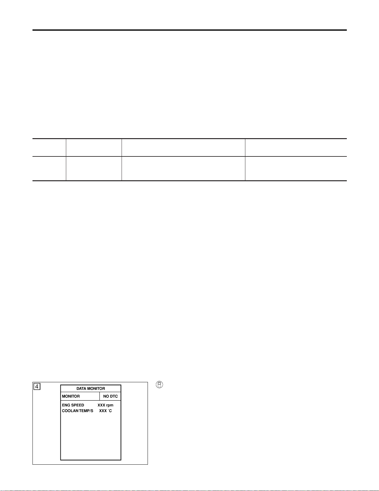
Description
NFEC0795
NOTE:
If DTC P0507 is displayed with other DTC, first perform the trouble diagnosis for the other DTC.
The ECM controls the engine idle speed to a specified level through the fine adjustment of the air, which is
let into the intake manifold, by operating the electric throttle control actuator. The operating of the throttle valve
is varied to allow for optimum control of the engine idling speed. The crankshaft position sensor (POS) detects
the actual engine speed and sends a signal to the ECM.
The ECM controls the electric throttle control actuator so that the engine speed coincides with the target value
memorized in the ECM. The target engine speed is the lowest speed at which the engine can operate steadly.
The optimum value stored in the ECM is determined by taking into consideration various engine conditions,
such as during warming up, deceleration, and engine load (air conditioner, power steering and cooling fan
operation, etc.).
On Board Diagnosis Logic
NFEC0798
DTC No.
Trouble diagnosis
name
DTC Detecting Condition Possible Cause
P0507
0507
Idle speed control
system RPM higher
than expected
The idle speed is not in the specified range. I Electric throttle control actuator
I Intake air leak
DTC Confirmation Procedure
NFEC0800
NOTE:
I If “DTC Confirmation Procedure” has been previously
conducted, always turn ignition switch “OFF” and wait at least
10 seconds before conducting the next test.
I If the target idle speed is out of the specified value, per-
form “Idle Air Volume Learning”, Idle Air Volume Learning
, before conducting “DTC Confirmation Procedure”. For
the target idle speed, refer to the “Service Data and Speci-
fications (SDS)”, EC-749.
TESTING CONDITION:
I Before performing the following procedure, confirm that
battery voltage is more than 11V at idle.
I Always perform the test at a temperature above −10°C
(14°F).
SEF174Y
WITH CONSULT-II
NFEC0800S03
1) Open engine hood.
2) Start engine and warm it up to normal operating temperature.
3) Turn ignition switch “OFF” and wait at least 10 seconds.
4) Turn ignition switch “ON” again and select “DATA MONITOR”
mode with CONSULT-II.
5) Start engine and run it for at least 1 minute at idle speed.
6) If 1st trip DTC is detected, go to “Diagnostic Procedure”,
EC-449.
DTC P0507 ISC SYSTEM
Description
EC-448
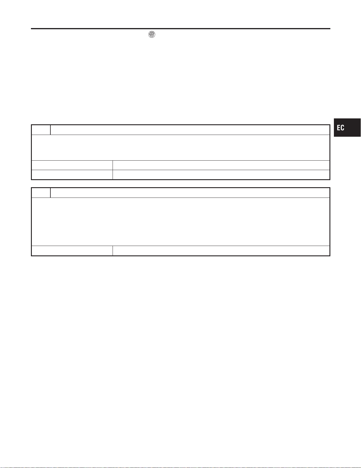
WITH GST
NFEC0800S04
Follow the procedure “With CONSULT-II” above.
Diagnostic Procedure
NFEC0802
1 CHECK INTAKE AIR LEAK
1. Start engine and let it idle.
2. Listen for an intake air leak after the mass air flow sensor.
OK or NG
OK © GO TO 2.
NG © Discover air leak location and repair.
2 REPLACE ECM
1. Stop engine.
2. Replace ECM.
3. Perform initialization of NVIS (NATS) system and registration of all NVIS (NATS) ignition key IDs. Refer to “NVIS (NIS-
SAN VEHICLE IMMOBILIZER SYSTEM — NATS)”, EC-92.
4. Perform “Accelerator Pedal Released Position Learning”, EC-71.
5. Perform “Throttle Valve Closed Position Learning”, EC-71.
6. Perform “Idle Air Volume Learning”, EC-71.
© INSPECTION END
GI
MA
EM
LC
FE
CL
MT
AT
AX
SU
BR
ST
RS
BT
HA
SC
EL
IDX
DTC P0507 ISC SYSTEM
DTC Confirmation Procedure (Cont’d)
EC-449
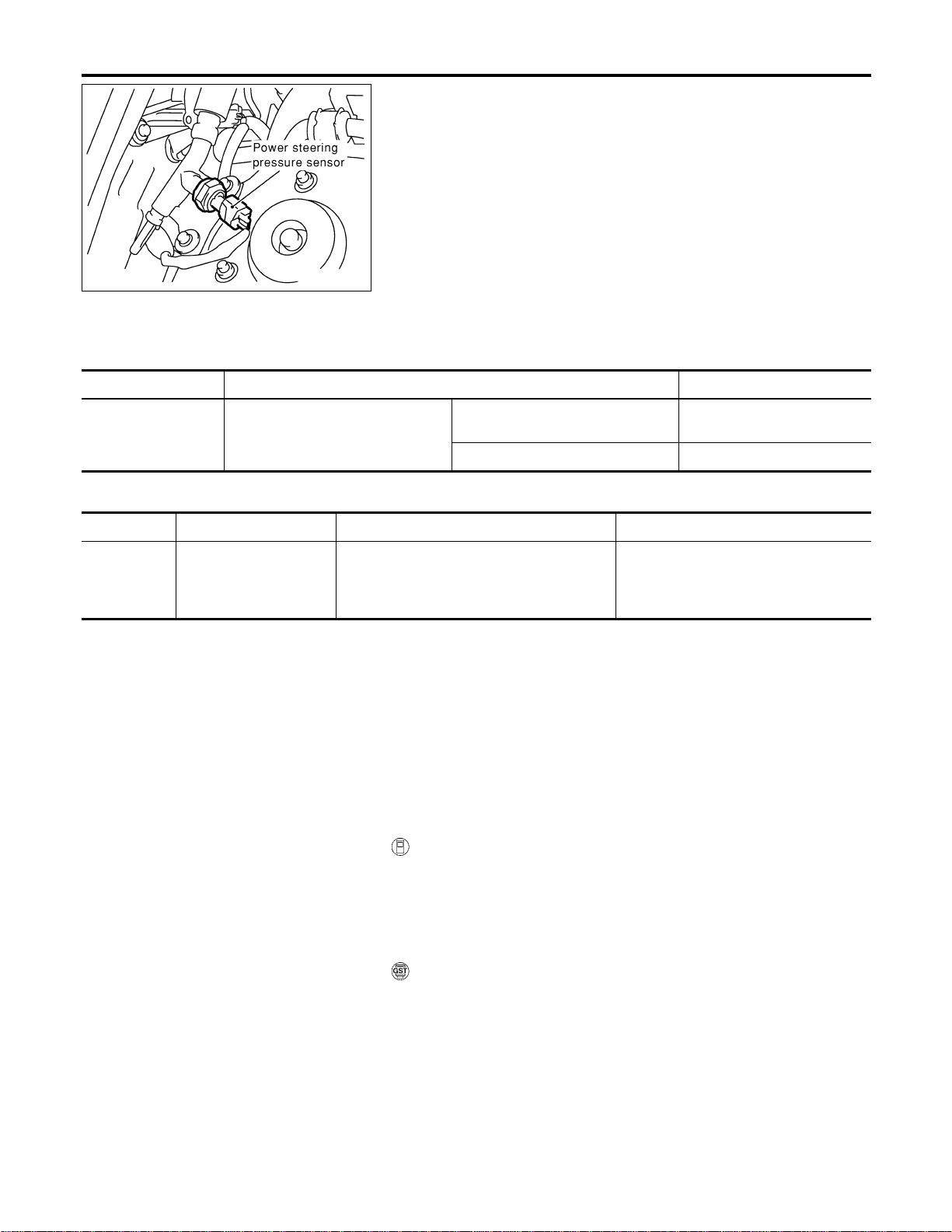
SEC046D
Component Description
NFEC1250
Power steering pressure (PSP) sensor is installed to the power
steering high-pressure tube and detects a power steering load.
This sensor is a potentiometer which transforms the power steer-
ing load into output voltage, and emits the voltage signal to the
ECM. The ECM controls the ETC actuator and adjusts the throttle
valve opening angle to increase the engine speed and adjusts the
idle speed for the increased load.
CONSULT-II Reference Value in Data Monitor
Mode
NFEC1256
Specification data are reference values.
MONITOR ITEM CONDITION SPECIFICATION
PW/ST SIGNAL
I Engine: After warming up, idle the
engine
Steering wheel is in neutral position.
(Forward direction)
OFF
Steering wheel is turned. ON
On Board Diagnosis Logic
NFEC1251
DTC No. Trouble diagnosis name DTC detecting condition Possible cause
P0550
0550
Power steering pressure
sensor circuit
An excessively low or high voltage from the
sensor is sent to ECM.
I Harness or connectors
(The sensor circuit is open or
shorted.)
I Power steering pressure sensor
DTC Confirmation Procedure
NFEC1252
NOTE:
If “DTC Confirmation Procedure” has been previously conducted,
always turn ignition switch “OFF” and wait at least 10 seconds
before conducting the next test.
With CONSULT-II
1. Turn ignition switch “ON”.
2. Select “DATA MONITOR” mode with CONSULT-II.
3. Start engine and let it idle for at least 5 seconds.
4. If 1st trip DTC is detected, go to EC-452, “Diagnostic Proce-
dure”.
With GST
Follow the procedure “WITH CONSULT-II” above.
DTC P0550 PSP SENSOR
Component Description
EC-450
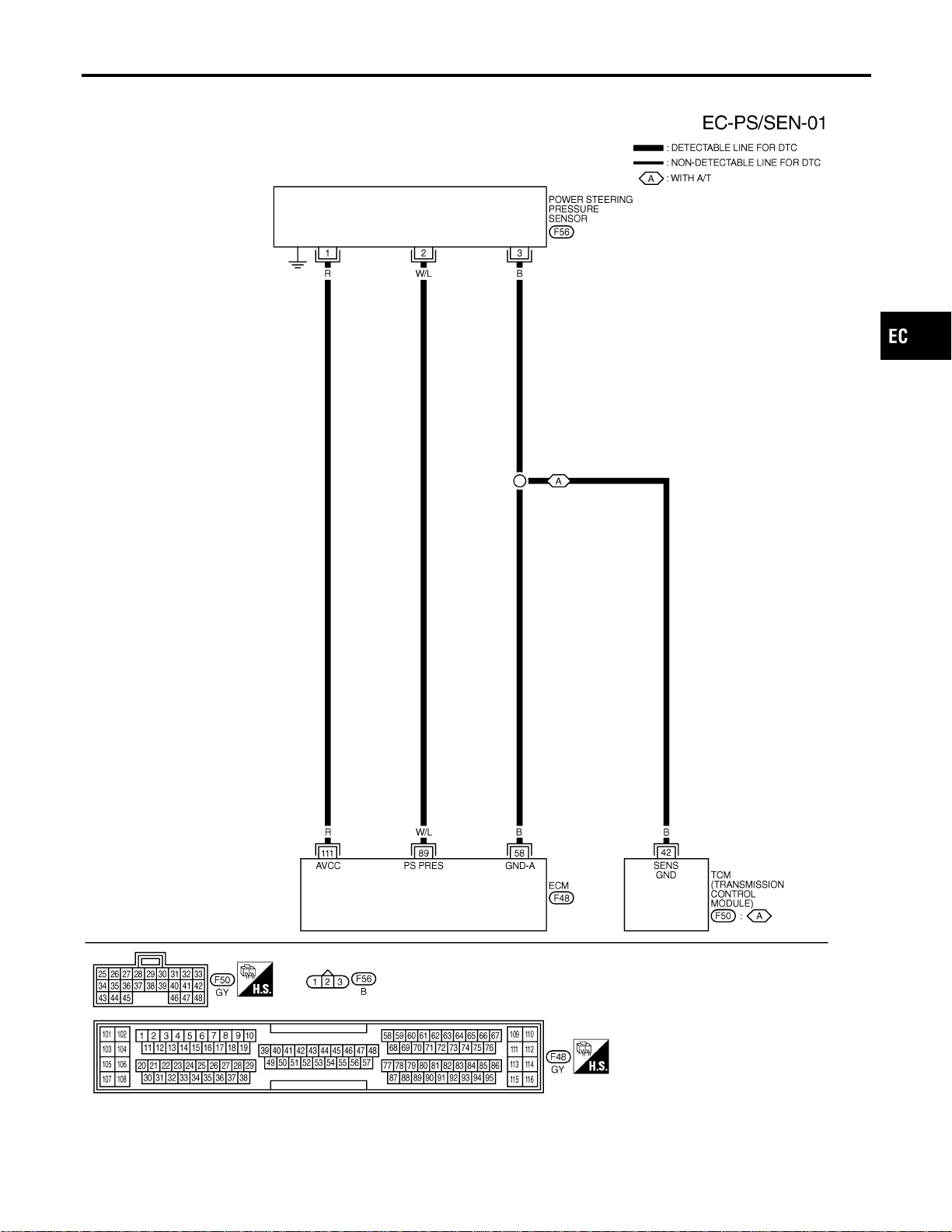
Wiring Diagram
NFEC1253
MEC516D
GI
MA
EM
LC
FE
CL
MT
AT
AX
SU
BR
ST
RS
BT
HA
SC
EL
IDX
DTC P0550 PSP SENSOR
Wiring Diagram
EC-451
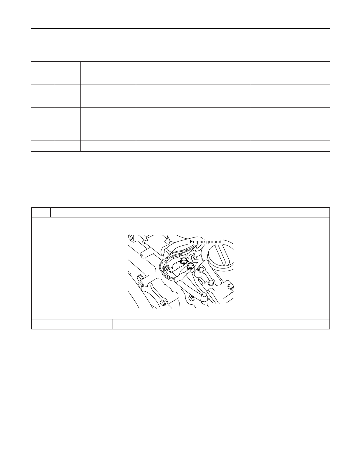
Specification data are reference values and are measured between each terminal and body ground.
CAUTION:
Do not use ECM ground terminals when measuring input/output voltage. Doing so may result in dam-
age to the ECM’s transistor. Use a ground other than ECM terminals, such as the ground.
TER-
MINAL
NO.
WIRE
COLOR
ITEM CONDITION DATA (DC Voltage)
58 B Sensors’ ground
[Engine is running]
I Warm-up condition
I Idle speed
Approximately 0V
89 W/L
Power steering pres-
sure sensor
[Engine is running]
I Steering wheel is being turned.
0.5 - 4.0V
[Engine is running]
I Steering wheel is not being turned.
0.4 - 0.8V
111 R Sensors’ power supply [Ignition switch “ON”] Approximately 5V
Diagnostic Procedure
NFEC1254
1 RETIGHTEN GROUND SCREWS
1. Turn ignition switch “OFF”.
2. Loosen and retighten engine ground screws.
SEC047D
© GO TO 2.
DTC P0550 PSP SENSOR
Wiring Diagram (Cont’d)
EC-452
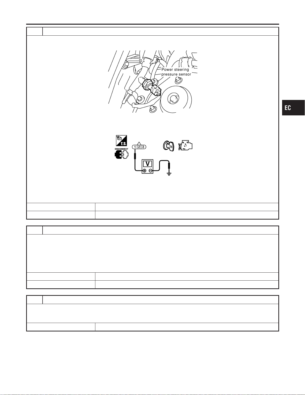
2 CHECK PSP SENSOR POWER SUPPLY CIRCUIT
1. Disconnect PSP sensor harness connector.
2. Turn ignition switch “ON”.
SEC046D
3. Check voltage between PSP sensor terminal 1 and ground with CONSULT-II or tester.
SEC048D
Voltage: Approximately 5V
OK or NG
OK © GO TO 3.
NG © Repair harness or connectors.
3 CHECK PSP SENSOR GROUND CIRCUIT FOR OPEN AND SHORT
1. Turn ignition switch “OFF”.
2. Check harness continuity between PSP sensor terminal 3 and engine ground.
Refer to Wiring Diagram.
Continuity should exist.
3. Also check harness for short to power.
OK or NG
OK © GO TO 5.
NG © GO TO 4.
4 DETECT MALFUNCTIONING PART
Check the following.
I Harness for open or short between ECM and PSP sensor
I Harness for open or short between TCM (Transmission Control Module) and PSP sensor.
© Repair open circuit or short to ground or short to power in harness or connectors.
GI
MA
EM
LC
FE
CL
MT
AT
AX
SU
BR
ST
RS
BT
HA
SC
EL
IDX
DTC P0550 PSP SENSOR
Diagnostic Procedure (Cont’d)
EC-453
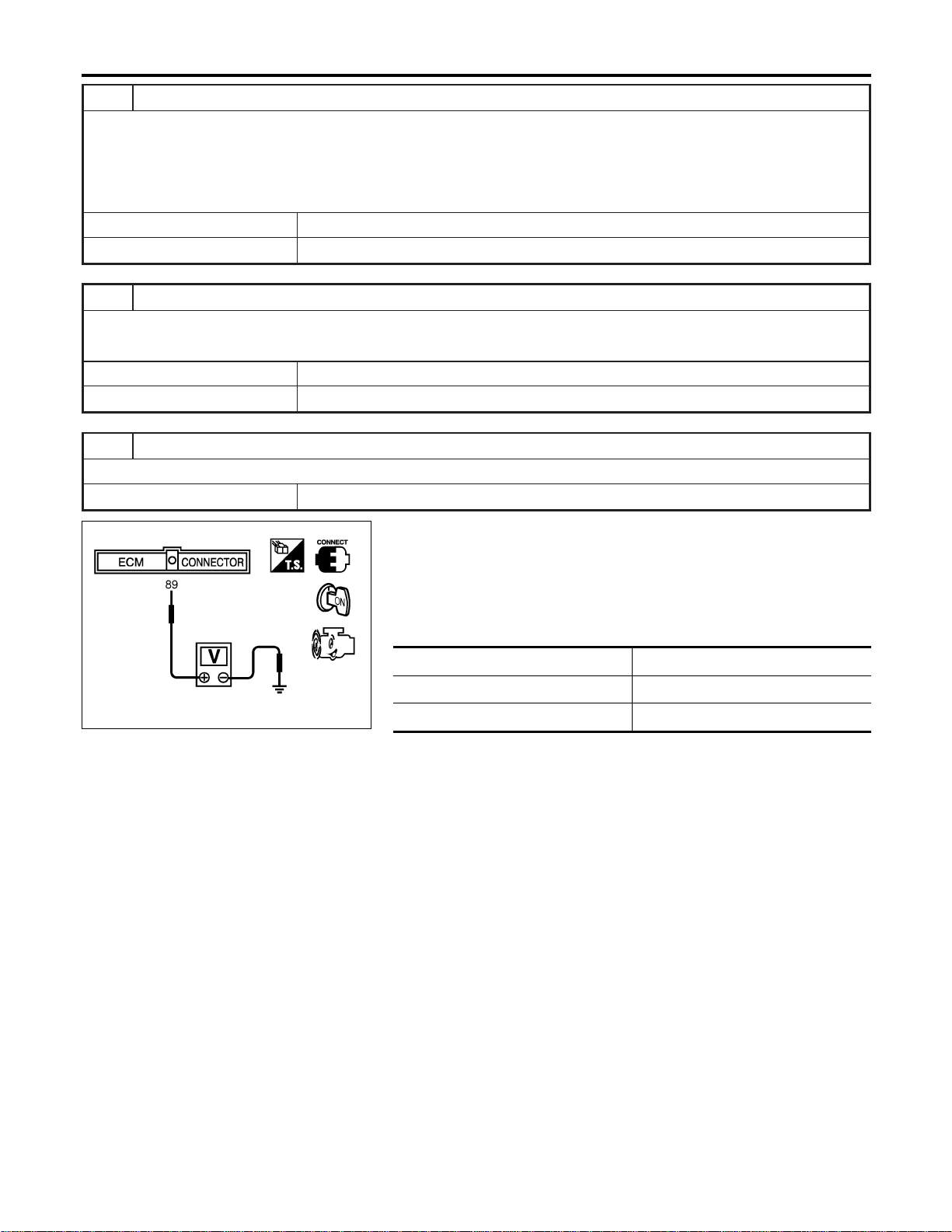
5 CHECK PSP SENSOR INPUT SIGNAL CIRCUIT FOR OPEN AND SHORT
1. Disconnect ECM harness connector.
2. Check harness continuity between ECM terminal 89 and PSP sensor terminal 2.
Continuity should exist.
3. Also check harness for short to ground and short to power.
OK or NG
OK © GO TO 6.
NG © Repair open circuit or short to ground or short to power in harness or connectors.
6 CHECK PSP SENSOR
Refer to “Component Inspection”, EC-454.
OK or NG
OK © GO TO 7.
NG © Replace PSP sensor.
7 CHECK INTERMITTENT INCIDENT
Refer to “TROUBLE DIAGNOSIS FOR INTERMITTENT INCIDENT”, EC-156.
© INSPECTION END
SEC049D
Component Inspection
NFEC1257
POWER STEERING PRESSURE SENSOR
1. Reconnect all harness connectors disconnected.
2. Start engine and let it idle.
3. Check voltage between ECM terminal 89 and ground under
the following conditions.
Condition Voltage
Steering wheel is turned fully. Approximately 3.6V
Steering wheel is not turned. Approximately 0.6V
DTC P0550 PSP SENSOR
Diagnostic Procedure (Cont’d)
EC-454
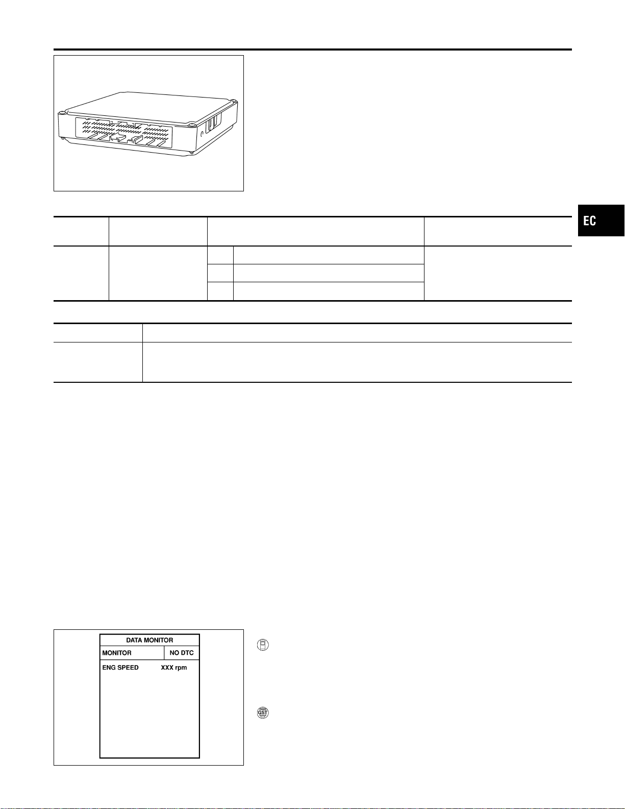
SEF093X
Component Description
NFEC1032
The ECM consists of a microcomputer and connectors for signal
input and output and for power supply. The unit controls the engine.
On Board Diagnosis Logic
NFEC1033
DTC No.
Trouble diagnosis
name
DTC Detecting Condition Possible Cause
P0605
0605
Engine control module
A) ECM calculation function is malfunctioning.
I ECMB) ECM EEP-ROM system is malfunctioning.
C) ECM self shut-off function is malfunctioning.
FAIL-SAFE MODE
Detected items Engine operation condition in fail-safe mode
Malfunction A
I ECM stops the electric throttle control actuator control, throttle valve is maintained at a fixed opening
(approx. 5 degrees) by the return spring.
I ECM deactivates ASCD operation.
DTC Confirmation Procedure
NFEC1445
Perform “PROCEDURE FOR MALFUNCTION A” first. If the 1st
trip DTC cannot be confirmed, perform “PROCEDURE FOR
MALFUNCTION B”. If there is no problem on “PROCEDURE
FOR MALFUNCTION B”, perform “PROCEDURE FOR MAL-
FUNCTION C”.
NOTE:
If “DTC Confirmation Procedure” has been previously conducted,
always turn ignition switch “OFF” and wait at least 10 seconds
before conducting the next test.
SEF058Y
PROCEDURE FOR MALFUNCTION A
With CONSULT-II
1) Turn ignition switch “ON”.
2) Select “DATA MONITOR” mode with CONSULT-II.
3) If 1st trip DTC is detected, go to EC-456, “Diagnostic Proce-
dure”.
With GST
Follow the procedure “With CONSULT-II” above.
GI
MA
EM
LC
FE
CL
MT
AT
AX
SU
BR
ST
RS
BT
HA
SC
EL
IDX
DTC P0605 ECM
Component Description
EC-455
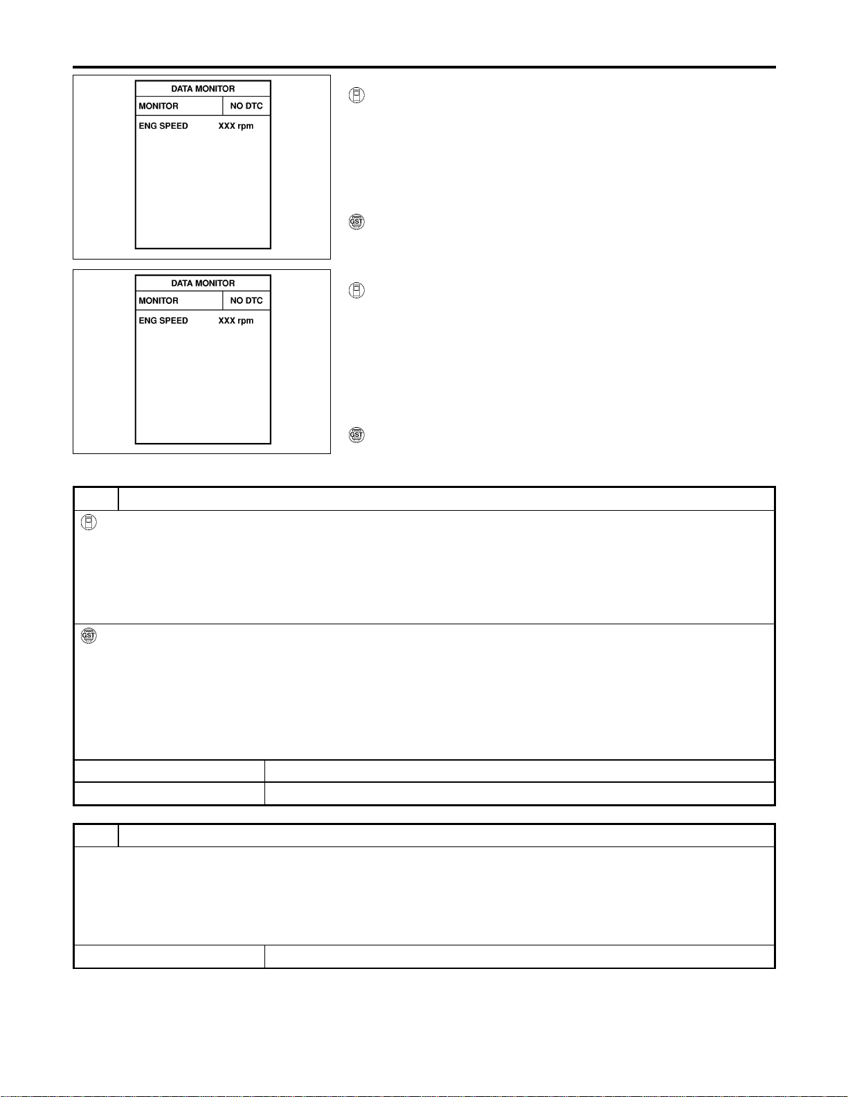
SEF058Y
PROCEDURE FOR MALFUNCTION B
With CONSULT-II
1) Turn ignition switch “ON” and wait at least 1 second.
2) Select “DATA MONITOR” mode with CONSULT-II.
3) Turn ignition switch “OFF”, wait at least 10 seconds, and then
turn “ON”.
4) If 1st trip DTC is detected, go to EC-456, “Diagnostic Proce-
dure”.
With GST
Follow the procedure “With CONSULT-II” above.
SEF058Y
PROCEDURE FOR MALFUNCTION C
With CONSULT-II
1) Turn ignition switch “ON” and wait at least 1 second.
2) Select “DATA MONITOR” mode with CONSULT-II.
3) Turn ignition switch “OFF”, wait at least 10 seconds, and then
turn “ON”.
4) Repeat step 3 procedure, 32 times.
5) If 1st trip DTC is detected, go to EC-456, “Diagnostic Proce-
dure”.
With GST
Follow the procedure “With CONSULT-II” above.
Diagnostic Procedure
NFEC1035
1 INSPECTION START
With CONSULT-II
1. Turn ignition switch “ON”.
2. Select “SELF DIAG RESULTS” mode with CONSULT-II.
3. Touch “ERASE”.
4. Perform “DTC Confirmation Procedure”.
See EC-455.
5. Is the 1st trip DTC P0605 displayed again?
With GST
1. Turn ignition switch “ON”.
2. Select MODE 4 with GST.
3. Touch “ERASE”.
4. Perform “DTC Confirmation Procedure”.
See EC-455.
5. Is the 1st trip DTC P0605 displayed again?
YesorNo
Yes © GO TO 2.
No © INSPECTION END
2 REPLACE ECM
1. Replace ECM.
2. Perform initialization of NVIS (NATS) system and registration of all NVIS (NATS) ignition key IDs. Refer to “NVIS (NIS-
SAN VEHICLE IMMOBILIZER SYSTEM — NATS)”, EC-92.
3. Perform “Accelerator Pedal Released Position Learning”, EC-71.
4. Perform “Throttle Valve Closed Position Learning”, EC-71.
5. Perform “Idle Air Volume Learning”, EC-71.
© INSPECTION END
DTC P0605 ECM
DTC Confirmation Procedure (Cont’d)
EC-456
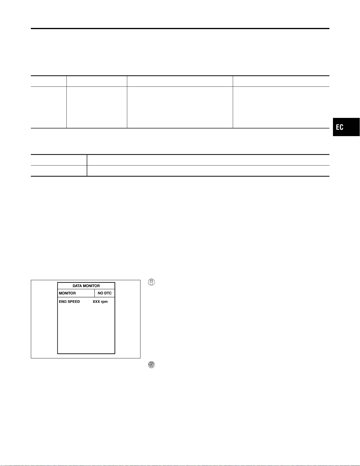
Component Description
NFEC1258
Malfunction Indicator Lamp (MIL) is located on the instrument panel. When the ignition switch is turned ON
without engine running, MIL will light up. This is a bulb check. When the engine is started, MIL should go off.
If MIL remains on, the on board diagnostic system has detected an engine system malfunction.
On Board Diagnosis Logic
NFEC1259
DTC No. Trouble diagnosis name DTC detecting condition Possible cause
P0650
0650
Malfunction indicator
(MIL) control circuit
I An excessively high voltage is sent to ECM
through the MIL circuit under the condition
that calls for MIL light up.
I An excessively low voltage is sent to ECM
through the MIL circuit under the condition
that calls for MIL not to light up.
I Harness or connectors
(MIL circuit is open or shorted.)
I MIL
FAIL-SAFE MODE
ECM enters in fail-safe mode when both DTC P0650 and another DTC, which calls for MIL to light up, are
detected at the same time.
Detected items Engine operating condition in fail-safe mode
MIL circuit Engine speed will not rise more than 2,500 rpm due to the fuel cut.
DTC Confirmation Procedure
NFEC1260
NOTE:
If “DTC Confirmation Procedure” has been previously conducted,
always turn ignition switch “OFF” and wait at least 10 seconds
before conducting the next test.
SEF058Y
With CONSULT-II
1. Turn ignition switch “ON” and wait at least 1 second.
2. Select “DATA MONITOR” mode with CONSULT-II.
3. Start engine and let it idle for 1 second.
4. If 1st trip DTC is detected, go to “Diagnostic Procedure”,
EC-459.
WITH GST
Follow the procedure “WITH CONSULT-II” above.
GI
MA
EM
LC
FE
CL
MT
AT
AX
SU
BR
ST
RS
BT
HA
SC
EL
IDX
DTC P0650 MIL (CIRCUIT)
Component Description
EC-457
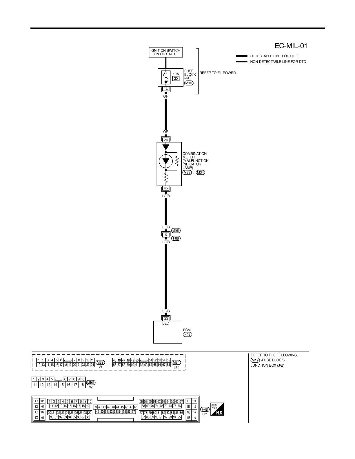
Wiring Diagram
NFEC1261
MEC519D
DTC P0650 MIL (CIRCUIT)
Wiring Diagram
EC-458

Specification data are reference values and are measured between each terminal and body ground.
CAUTION:
Do not use ECM ground terminals when measuring input/output voltage. Doing so may result in dam-
age to the ECM’s transistor. Use a ground other than ECM terminals, such as the ground.
TER-
MINAL
NO.
WIRE
COLOR
ITEM CONDITION DATA (DC Voltage)
33 LG/B MIL
[Ignition switch “ON”] 0 - 1.0V
[Engine is running]
I Idle speed
BATTERY VOLTAGE
(11 - 14V)
Diagnostic Procedure
NFEC1262
1 CHECK MIL POWER SUPPLY CIRCUIT
1. Turn ignition switch “OFF”.
2. Disconnect combination meter harness connector.
3. Turn ignition switch “ON”.
4. Check voltage between combination meter terminal 24 and ground with CONSULT-II or tester.
SEC050D
Voltage: Battery voltage
OK or NG
OK © GO TO 3.
NG © GO TO 2.
2 DETECT MALFUNCTIONING PART
Check the following.
I Fuse block (J/B) connector M19
I 10A fuse
I Harness for open or short between fuse block (J/B) and combination meter
© Repair harness or connectors.
3 CHECK MIL OUTPUT SIGNAL CIRCUIT FOR OPEN AND SHORT
1. Turn ignition switch “OFF”.
2. Disconnect ECM harness connector.
3. Check harness continuity between ECM terminal 33 and combination meter terminal 45.
Refer to Wiring Diagram.
Continuity should exist.
4. Also check harness for short to ground and short to power.
OK or NG
OK © GO TO 5.
NG © GO TO 4.
GI
MA
EM
LC
FE
CL
MT
AT
AX
SU
BR
ST
RS
BT
HA
SC
EL
IDX
DTC P0650 MIL (CIRCUIT)
Wiring Diagram (Cont’d)
EC-459
4 DETECT MALFUNCTIONING PART
Check the following.
I Harness connectors M161, F68
I Harness for open or short between ECM and combination meter
© Repair open circuit or short to ground or short to power in harness or connectors.
5 CHECK INTERMITTENT INCIDENT
Refer to “TROUBLE DIAGNOSIS FOR INTERMITTENT INCIDENT”, EC-156.
OK or NG
OK © Replace combination meter. Refer to EL-117, “METERS AND GAUGES”.
NG © Repair or replace.
DTC P0650 MIL (CIRCUIT)
Diagnostic Procedure (Cont’d)
EC-460
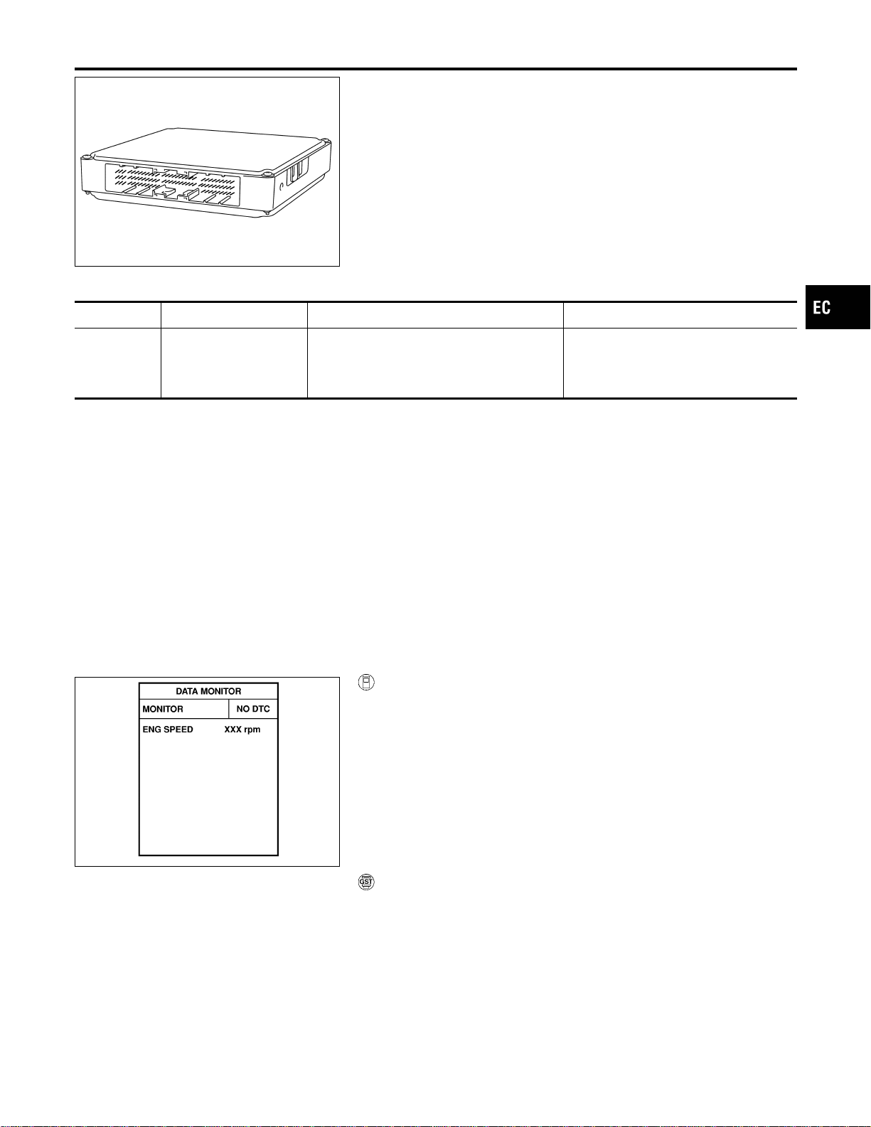
SEF093X
Component Description
NFEC1263
Battery voltage is supplied to the ECM even when the ignition
switch is turned OFF for the ECM memory function of the DTC
memory, the air fuel ratio feedback compensation value memory,
the idle air volume learning value memory, etc.
On Board Diagnosis Logic
NFEC1264
DTC No. Trouble diagnosis name DTC detecting condition Possible cause
P1065
1065
ECM power supply cir-
cuit
ECM back-up RAM system does not function
properly.
I Harness or connectors
[ECM power supply (back-up) circuit
is open or shorted.]
I ECM
DTC Confirmation Procedure
NFEC1265
NOTE:
If “DTC Confirmation Procedure” has been previously conducted,
always turn ignition switch “OFF” and wait at least 10 seconds
before conducting the next test.
SEF058Y
With CONSULT-II
1. Turn ignition switch “ON” and wait at least 1 second.
2. Select “DATA MONITOR” mode with CONSULT-II.
3. Start engine and let it idle for 1 second.
4. Turn ignition switch “OFF”, wait at least 10 seconds, and then
turn “ON”.
5. Repeat steps 3 and 4 four times.
6. If 1st trip DTC is detected, go to “Diagnostic Procedure”,
EC-463.
With GST
Follow the procedure “WITH CONSULT-II” above.
GI
MA
EM
LC
FE
CL
MT
AT
AX
SU
BR
ST
RS
BT
HA
SC
EL
IDX
DTC P1065 ECM POWER SUPPLY (BACK UP)
Component Description
EC-461
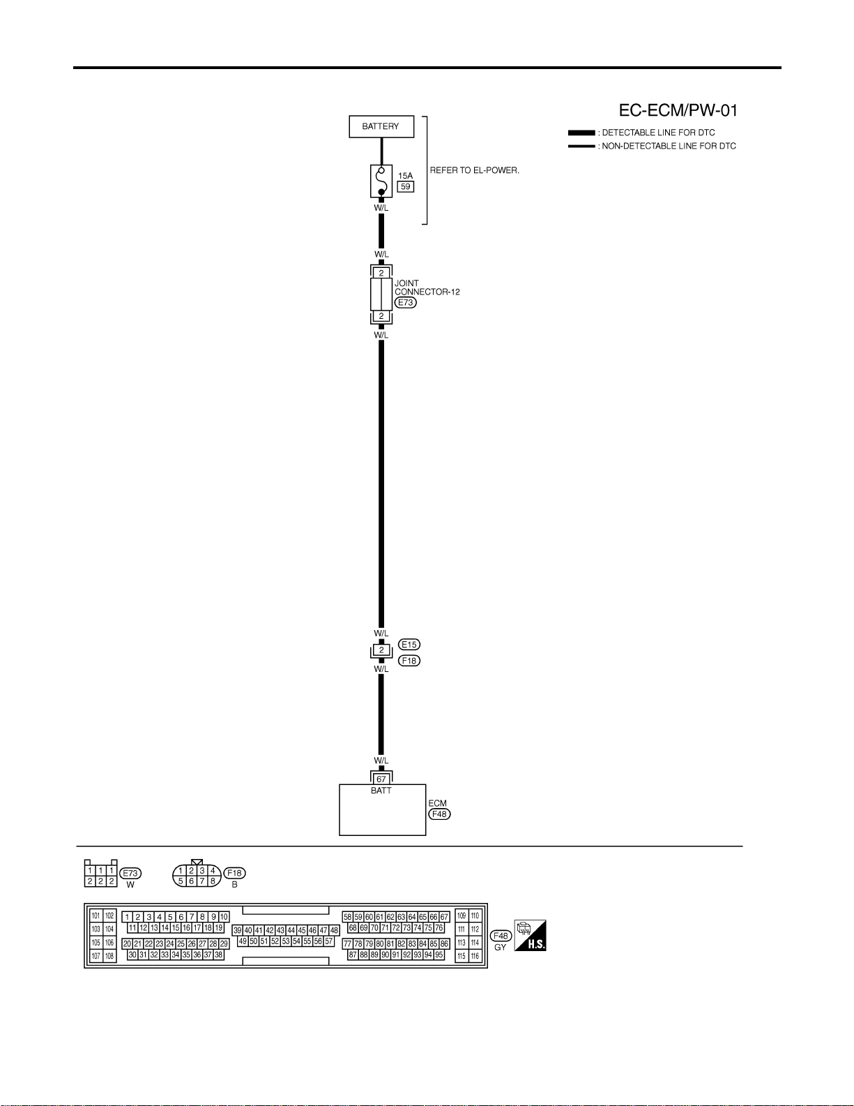
Wiring Diagram
NFEC1266
MEC805D
DTC P1065 ECM POWER SUPPLY (BACK UP)
Wiring Diagram
EC-462
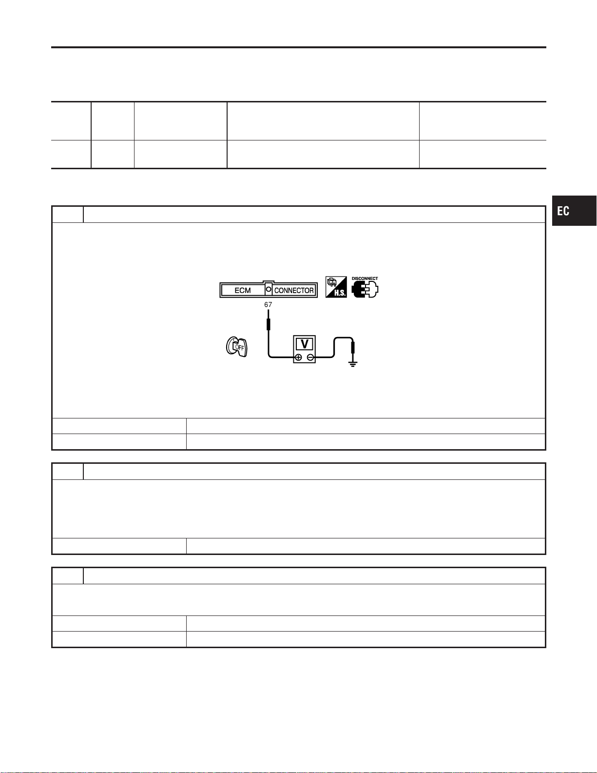
Specification data are reference values and are measured between each terminal and body ground.
CAUTION:
Do not use ECM ground terminals when measuring input/output voltage. Doing so may result in dam-
age to the ECM’s transistor. Use a ground other than ECM terminals, such as the ground.
TER-
MINAL
NO.
WIRE
COLOR
ITEM CONDITION DATA (DC Voltage)
67 W/L
Power supply for ECM
(Buck-up)
[Ignition switch “OFF”]
BATTERY VOLTAGE
(11 - 14V)
Diagnostic Procedure
NFEC1267
1 CHECK ECM POWER SUPPLY
1. Turn ignition switch “OFF”.
2. Disconnect ECM harness connector.
3. Check voltage between ECM terminal 67 and ground with CONSULT-II or tester.
SEC912C
Voltage: Battery voltage
OK or NG
OK © GO TO 3.
NG © GO TO 2.
2 DETECT MALFUNCTIONING PART
Check the following.
I Harness connectors E15, F18
I Joint connector-12
I 15A fuse
I Harness for open or short between ECM and fuse
© Repair or replace harness or connectors.
3 CHECK INTERMITTENT INCIDENT
Refer to “TROUBLE DIAGNOSIS FOR INTERMITTENT INCIDENT”, EC-156.
OK or NG
OK © GO TO 4.
NG © Repair or replace harness or connectors.
GI
MA
EM
LC
FE
CL
MT
AT
AX
SU
BR
ST
RS
BT
HA
SC
EL
IDX
DTC P1065 ECM POWER SUPPLY (BACK UP)
Wiring Diagram (Cont’d)
EC-463
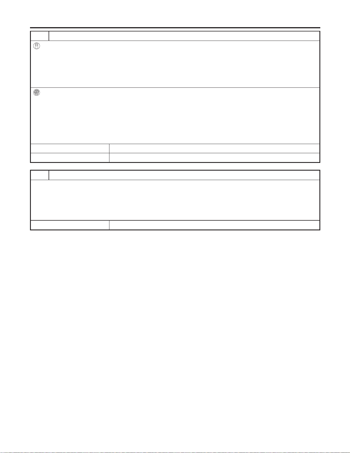
4 PERFORM DTC CONFIRMATION PROCEDURE
With CONSULT-II
1. Turn ignition switch “ON”.
2. Select “SELF DIAG RESULTS” mode with CONSULT-II.
3. Touch “ERASE”.
4. Perform “DTC Confirmation Procedure”.
See EC-461.
5. Is the 1st trip DTC P1065 displayed again?
With GST
1. Turn ignition switch “ON”.
2. Select MODE 4 with GST.
3. Touch “ERASE”.
4. Perform “DTC Confirmation Procedure”.
See EC-461.
5. Is the 1st trip DTC P1065 displayed again?
YesorNo
Yes © GO TO 5.
No © INSPECTION END
5 REPLACE ECM
1. Replace ECM.
2. Perform initialization of NVIS (NATS) system and registration of all NVIS (NATS) ignition key IDs. Refer to “NVIS (NIS-
SAN VEHICLE IMMOBILIZER SYSTEM — NATS)”, EC-92.
3. Perform “Accelerator Pedal Released Position Learning”, EC-71.
4. Perform “Throttle Valve Closed Position Learning”, EC-71.
5. Perform “Idle Air Volume Learning”, EC-71.
© INSPECTION END
DTC P1065 ECM POWER SUPPLY (BACK UP)
Diagnostic Procedure (Cont’d)
EC-464
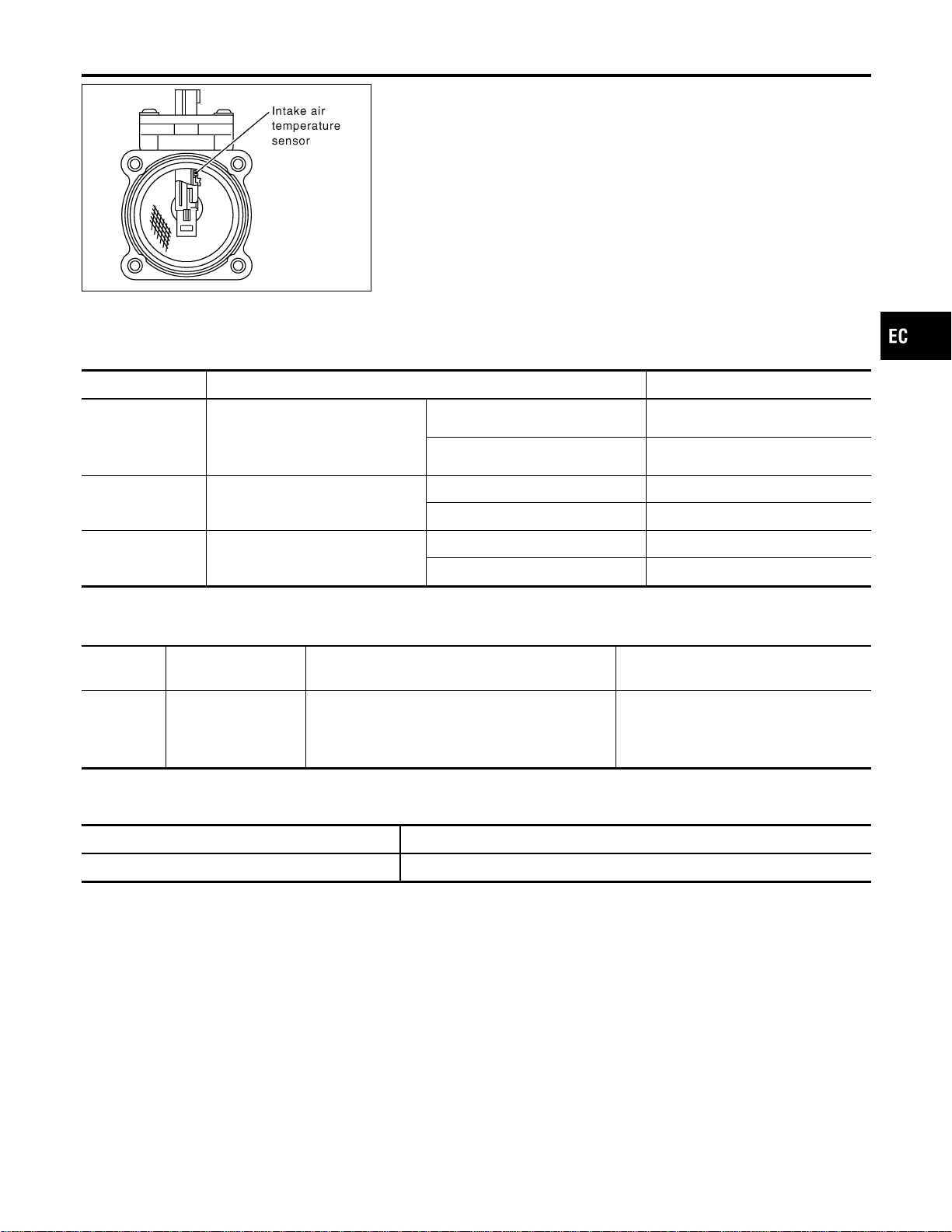
SEC266C
Component Description
NFEC0803
The mass air flow sensor is placed in the stream of intake air. It
measures the intake flow rate by measuring a part of the entire
intake flow. It consists of a hot film that is supplied with electric
current from the ECM. The temperature of the hot film is controlled
by the ECM a certain amount. The heat generated by the hot film
is reduced as the intake air flows around it. The more air, the
greater the heat loss.
Therefore, the ECM must supply more electric current to maintain
the temperature of the hot film as air flow increases. The ECM
detects the air flow by means of this current change.
CONSULT-II Reference Value in Data Monitor
Mode
NFEC0804
Specification data are reference values.
MONITOR ITEM CONDITION SPECIFICATION
MAS A/F SE-B1
I Engine: After warming up
I Air conditioner switch: “OFF”
I Shift lever: “N”
I No-load
Idle 1.1 - 1.5V
2,500 rpm 1.7 - 2.4V
CAL/LD VALUE ditto
Idle 10 - 35%
2,500 rpm 10 - 35%
MASS AIRFLOW ditto
Idle 2.0 - 6.0 g·m/s
2,500 rpm 7.0 - 20.0 g·m/s
On Board Diagnosis Logic
NFEC1446
This self-diagnosis has the one trip detection logic.
DTC No.
Trouble diagnosis
name
DTC Detecting Condition Possible Cause
P1102
1102
Mass air flow sensor
circuit range/
performance problem
A voltage from the sensor is constantly approx.
1.0V when engine is running.
I Harness or connectors
(The sensor circuit is open or
shorted.)
I Mass air flow sensor
FAIL-SAFE MODE
NFEC1446S01
When the malfunction is detected, the ECM enters fail-safe mode and the MIL lights up.
Detected items Engine operating condition in fail-safe mode
Mass air flow sensor circuit Engine speed will not rise more than 2,400 rpm due to the fuel cut.
DTC Confirmation Procedure
NFEC1447
NOTE:
If “DTC Confirmation Procedure” has been previously conducted,
always turn ignition switch “OFF” and wait at least 10 seconds
before conducting the next test.
GI
MA
EM
LC
FE
CL
MT
AT
AX
SU
BR
ST
RS
BT
HA
SC
EL
IDX
DTC P1102 MAF SENSOR
Component Description
EC-465
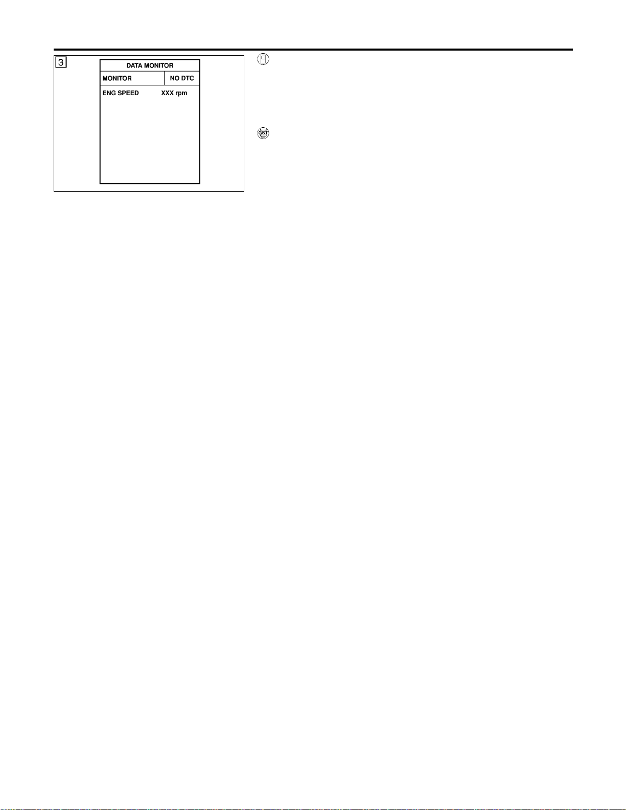
SEF058Y
WITH CONSULT-II
NFEC1447S01
1) Turn ignition switch “ON”.
2) Select “DATA MONITOR” mode with CONSULT-II.
3) Start engine and wait 5 seconds at most.
4) If DTC is detected, go to “Diagnostic Procedure”, EC-468.
WITH GST
NFEC1447S02
Follow the procedure “With CONSULT-II” above.
DTC P1102 MAF SENSOR
DTC Confirmation Procedure (Cont’d)
EC-466
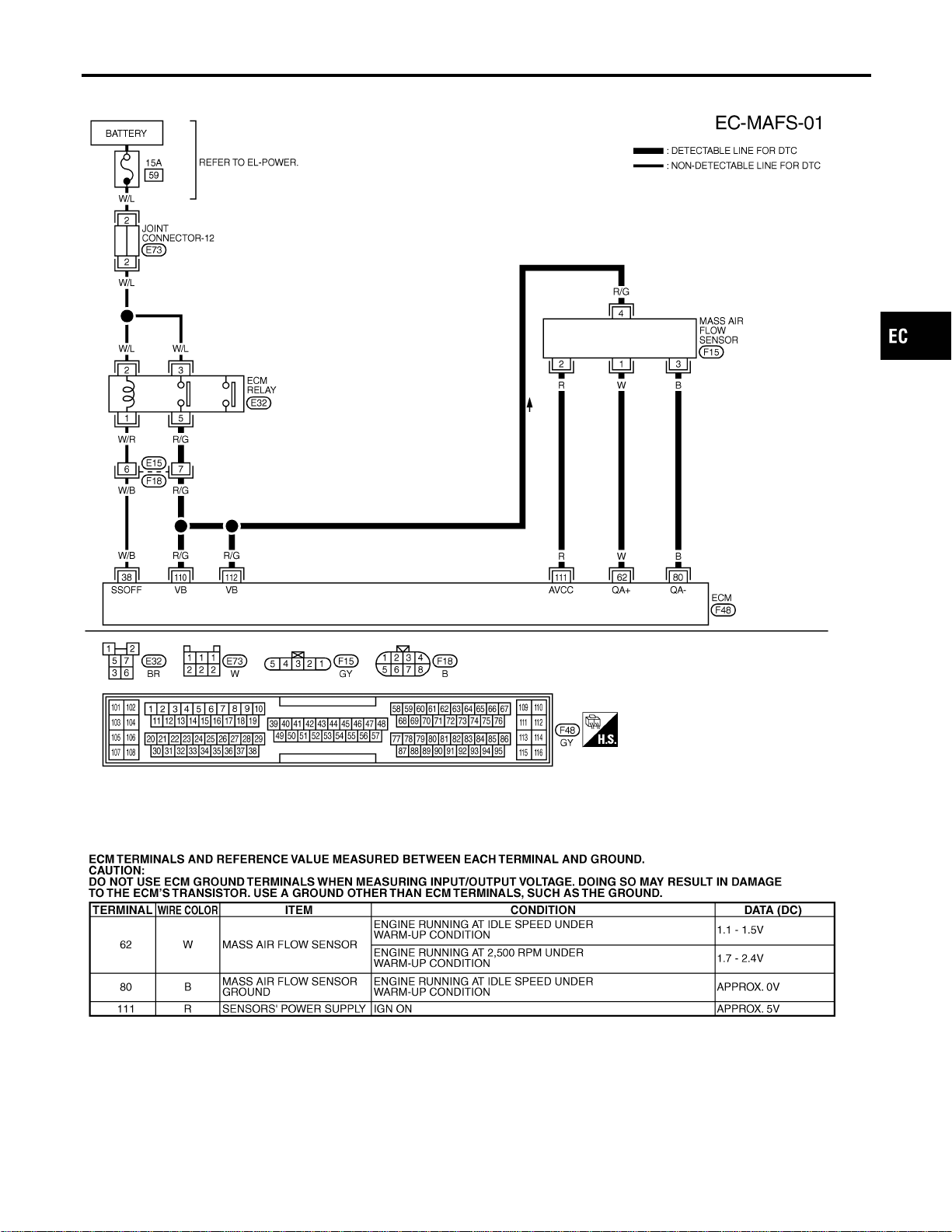
Wiring Diagram
=NFEC0810
MEC473D
SEF650XC
GI
MA
EM
LC
FE
CL
MT
AT
AX
SU
BR
ST
RS
BT
HA
SC
EL
IDX
DTC P1102 MAF SENSOR
Wiring Diagram
EC-467
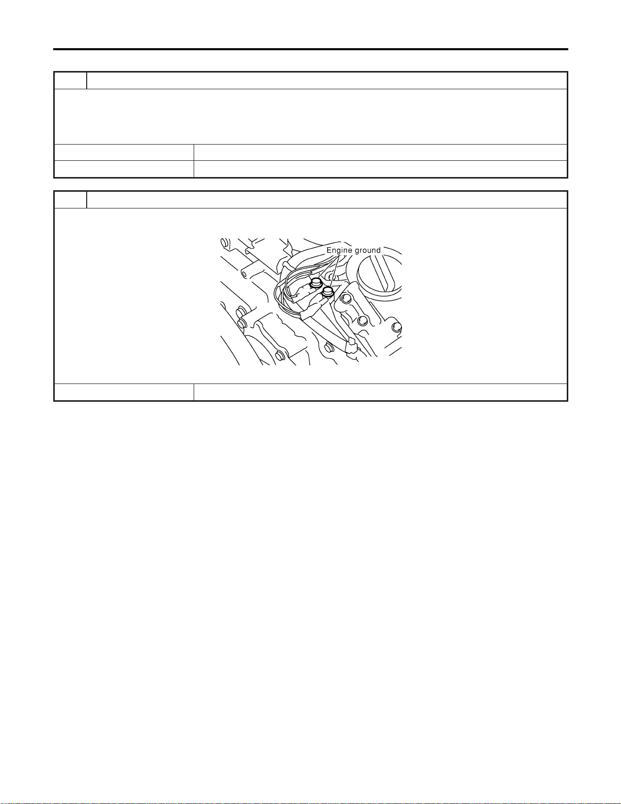
Diagnostic Procedure
=NFEC0811
1 CHECK INTAKE SYSTEM
Check the following for connection.
I Air duct
I Vacuum hoses
OK or NG
OK © GO TO 2.
NG © Reconnect the parts.
2 RETIGHTEN GROUND SCREWS
1. Turn ignition switch “OFF”.
2. Loosen and retighten engine ground screws.
SEC047D
© GO TO 3.
DTC P1102 MAF SENSOR
Diagnostic Procedure
EC-468
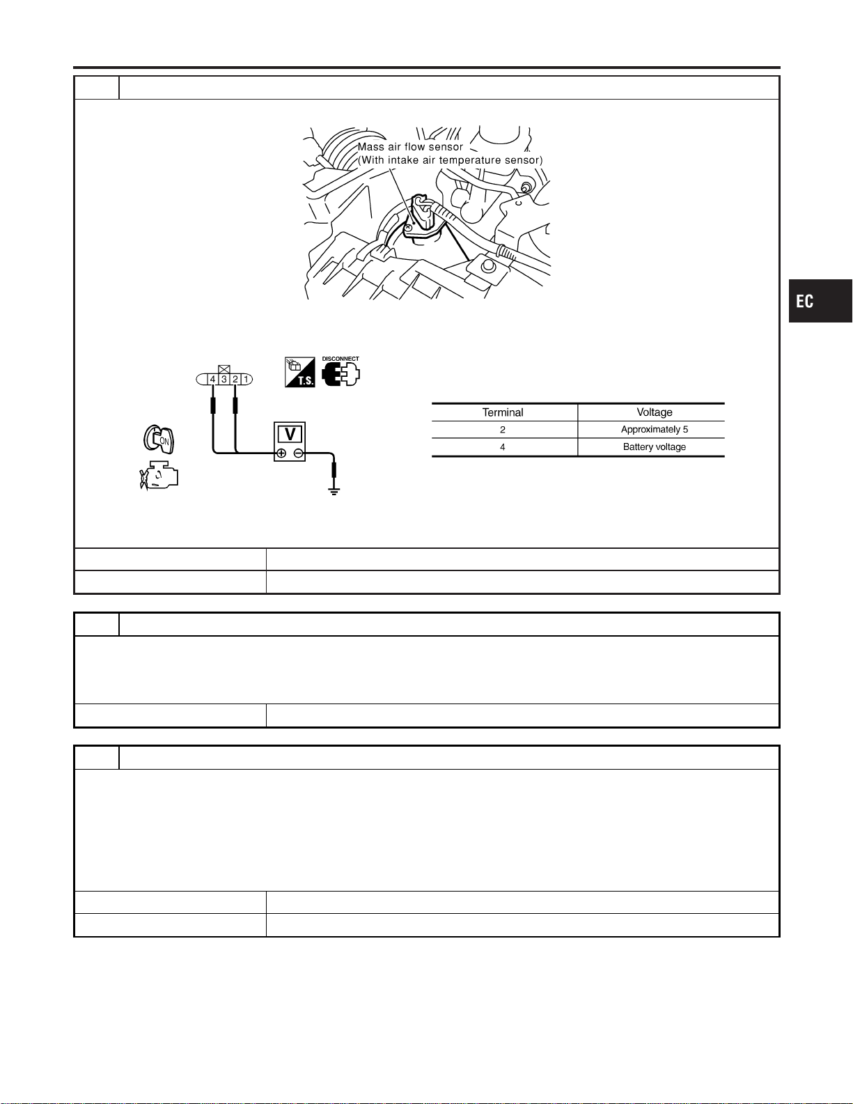
3 CHECK MAF SENSOR POWER SUPPLY CIRCUIT
1. Disconnect mass air flow (MAF) sensor harness connector.
SEC055D
2. Turn ignition switch “ON”.
3. Check voltage between MAF sensor terminals 2, 4 and ground with CONSULT-II or tester.
SEF297X
OK or NG
OK © GO TO 5.
NG © GO TO 4.
4 DETECT MALFUNCTIONING PART
Check the following.
I Harness connectors E15, F18
I Harness for open or short between ECM relay and mass air flow sensor
I Harness for open or short between mass air flow sensor and ECM
© Repair harness or connectors.
5 CHECK MAF SENSOR GROUND CIRCUIT FOR OPEN AND SHORT
1. Turn ignition switch “OFF”.
2. Disconnect ECM harness connector.
3. Check harness continuity between MAF sensor terminal 3 and ECM terminal 80.
Refer to Wiring Diagram.
Continuity should exist.
4. Also check harness for short to power.
OK or NG
OK © GO TO 6.
NG © Repair open circuit or short to power in harness or connectors.
GI
MA
EM
LC
FE
CL
MT
AT
AX
SU
BR
ST
RS
BT
HA
SC
EL
IDX
DTC P1102 MAF SENSOR
Diagnostic Procedure (Cont’d)
EC-469
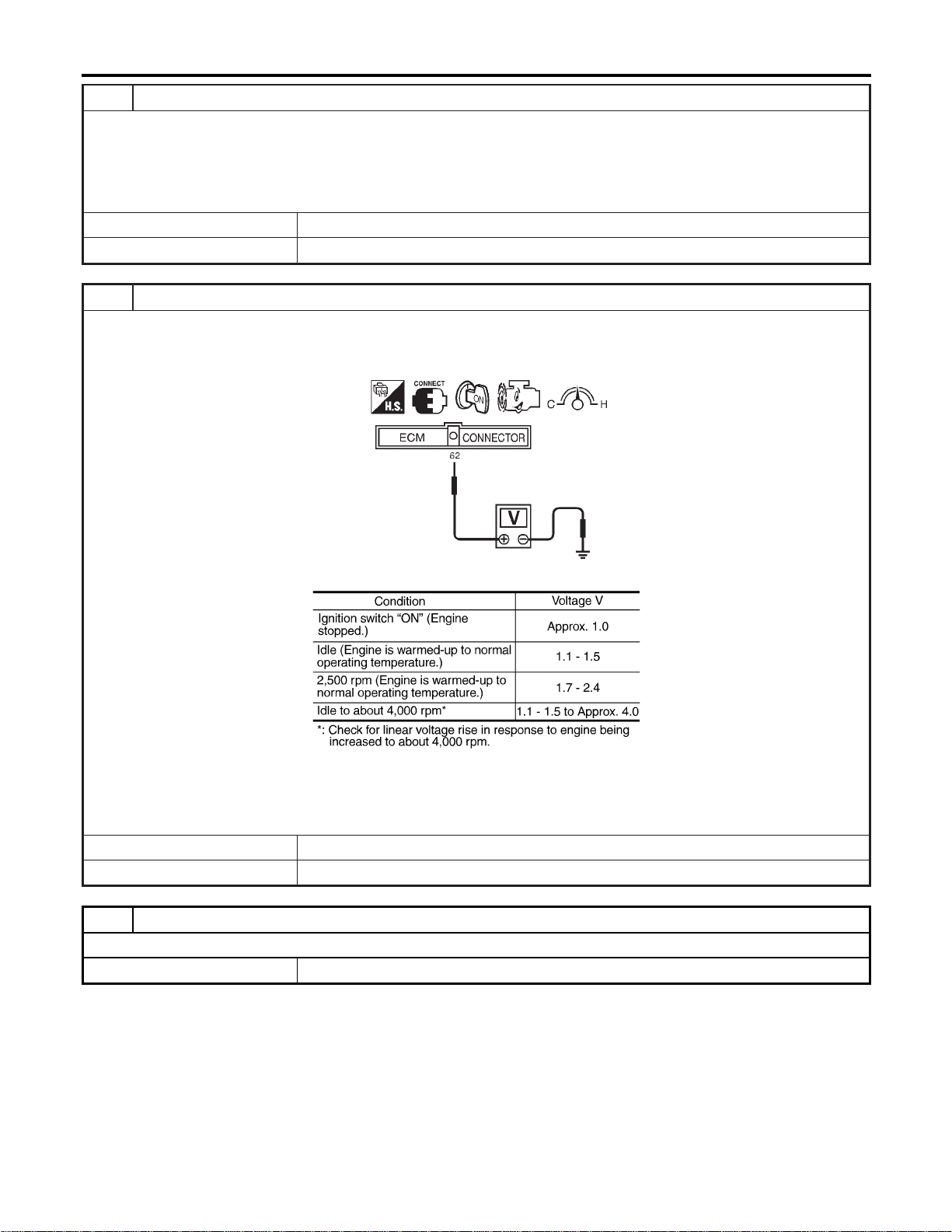
6 CHECK MAF SENSOR INPUT SIGNAL CIRCUIT FOR OPEN AND SHORT
1. Check harness continuity between MAF sensor terminal 1 and ECM terminal 62.
Refer to Wiring Diagram.
Continuity should exist.
2. Also check harness for short to ground and short to power.
OK or NG
OK © GO TO 7.
NG © Repair open circuit or short to ground or short to power in harness or connectors.
7 CHECK MASS AIR FLOW SENSOR
1. Reconnect harness connectors disconnected.
2. Start engine and warm it up to normal operating temperature.
3. Check voltage between ECM terminal 62 (Mass air flow sensor signal) and ground.
SEF391R
MTBL1160
4. If the voltage is out of specification, disconnect MAF sensor harness connector and connect it again.
Then repeat above check.
OK or NG
OK © GO TO 8.
NG © Replace mass air flow sensor.
8 CHECK INTERMITTENT INCIDENT
Refer to “TROUBLE DIAGNOSIS FOR INTERMITTENT INCIDENT”, EC-156.
© INSPECTION END
DTC P1102 MAF SENSOR
Diagnostic Procedure (Cont’d)
EC-470
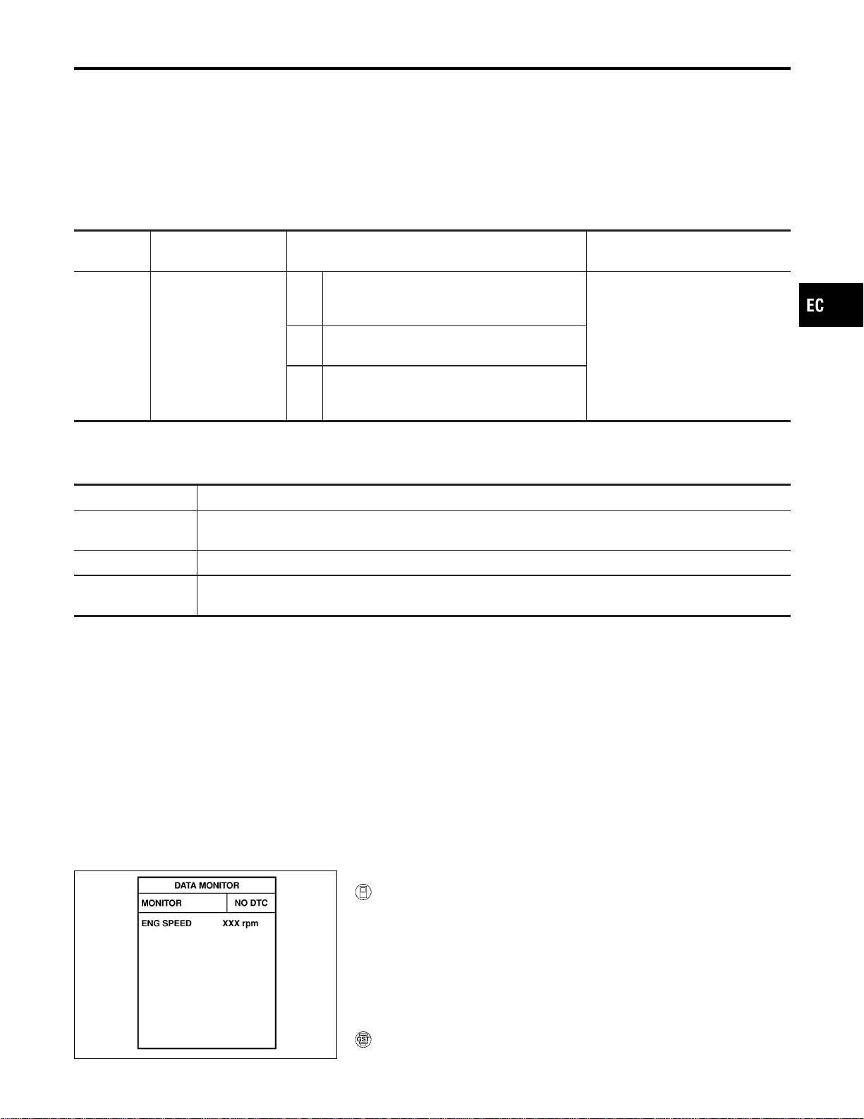
Component Description
NFEC1298
Electric Throttle Control Actuator consists of throttle control motor, throttle position sensor, etc.
The throttle control motor is operated by the ECM and it opens and closes the throttle valve.
The throttle position sensor detects the throttle valve position, and the opening and closing speed of the throttle
valve and feeds the voltage signals to the ECM. The ECM judges the current opening angle of the throttle
valve from these signals and the ECM controls the throttle control motor to make the throttle valve opening
angle properly in response to driving condition.
On Board Diagnosis Logic
NFEC1299
DTC No.
Trouble diagnosis
name
DTC detecting condition Possible cause
P1121
1121
Electric throttle control
actuator
A)
Electric throttle control actuator does not func-
tion properly due to the return spring malfunc-
tion.
I Electric throttle control actuatorB)
Throttle valve opening angle in fail-safe mode
is not in specified range.
C)
ECM detect the throttle valve is stuck open.
This self-diagnosis has the one trip detec-
tion logic.
FAIL-SAFE MODE
When the malfunction A or B is detected, ECM enters in fail-safe mode.
When the malfunction C is detected, ECM enters in fail-safe mode and the MIL lights up.
Detected items Engine operating condition in fail-safe mode
Malfunction A
The ECM controls the electric throttle throttle actuator by regulating the throttle opening around the idle
position. The engine speed will not rise more than 2,000 rpm.
Malfunction B ECM controls the electric throttle control actuator by regulating the throttle opening to 20 degrees or less.
Malfunction C
While the vehicle is driving, it slows down gradually by fuel cut. After the vehicle stops, the engine stalls.
The engine can restart in “N” or “P” position, and engine speed will not exceed 1,000 rpm or more.
DTC Confirmation Procedure
NFEC1300
NOTE:
I Perform “PROCEDURE FOR MALFUNCTION A AND B”
first. If the 1st trip DTC cannot be confirmed, perform
“PROCEDURE FOR MALFUNCTION C”.
If there is no problem on “PROCEDURE FOR MALFUNC-
TION A AND B”, perform “PROCEDURE FOR MALFUNC-
TION C”.
I If “DTC Confirmation Procedure” has been previously
conducted, always turn ignition switch “OFF” and wait at least
10 seconds before conducting the next test.
SEF058Y
PROCEDURE FOR MALFUNCTION A AND B
With CONSULT-II
1) Turn ignition switch “ON” and wait at least 1 second.
2) Select “DATA MONITOR” mode with CONSULT-II.
3) Shift selector lever to “D” position and wait at least 2 seconds.
4) Turn ignition switch “OFF”, wait at least 10 seconds, and then
turn “ON”.
5) If 1st trip DTC is detected, go to “Diagnostic Procedure”,
EC-472.
With GST
Follow the procedure “WITH CONSULT-II” above.
GI
MA
EM
LC
FE
CL
MT
AT
AX
SU
BR
ST
RS
BT
HA
SC
EL
IDX
DTC P1121 ELECTRIC THROTTLE CONTROL ACTUATOR
Component Description
EC-471
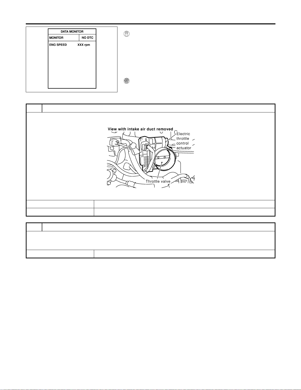
SEF058Y
PROCEDURE FOR MALFUNCTION C
With CONSULT-II
1) Turn ignition switch “ON” and wait at least 1 second.
2) Select “DATA MONITOR” mode with CONSULT-II.
3) Shift selector lever to “D” position and wait at least 2 seconds.
4) Shift selector lever to “N” or “P” position.
5) Start engine and let it idle for 3 seconds.
6) If DTC is detected, go to “Diagnostic Procedure”, EC-472.
With GST
Follow the procedure “WITH CONSULT-II” above.
Diagnostic Procedure
NFEC1413
1 CHECK ELECTRIC THROTTLE CONTROL ACTUATOR VISUALLY
1. Remove the intake air duct.
2. Check if a foreign matter is caught between the throttle valve and the housing.
SEC083D
OK or NG
OK © GO TO 2.
NG © Remove the foreign matter and clean the electric throttle control actuator inside.
2 REPLACE ELECTRIC THROTTLE CONTROL ACTUATOR
1. Replace the electric throttle control actuator.
2. Perform “Throttle Valve Closed Position Learning”, EC-71.
3. Perform “Idle Air Volume Learning”, EC-71.
© INSPECTION END
DTC P1121 ELECTRIC THROTTLE CONTROL ACTUATOR
DTC Confirmation Procedure (Cont’d)
EC-472
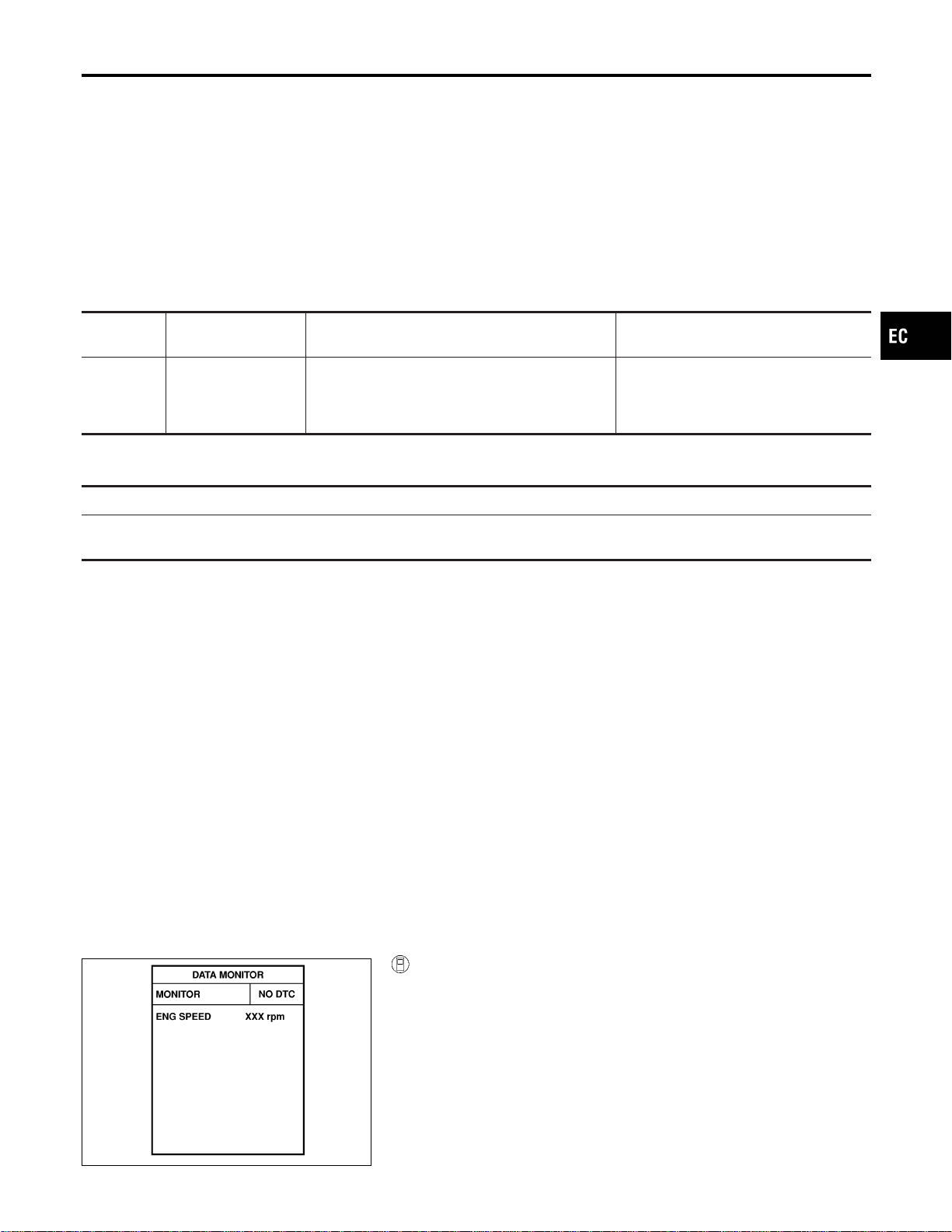
Description
NFEC1301
NOTE:
If DTC P1122 is displayed with DTC P1121 or P1126, first perform the trouble diagnosis for DTC P1121
or P1126. Refer to EC-471, 481.
Electric Throttle Control Actuator consists of throttle control motor, throttle position sensor, etc.
The throttle control motor is operated by the ECM and it opens and closes the throttle valve.
The current opening angle of the throttle valve is detected by the throttle position sensor and it provides the
feedback to the ECM to control the throttle control motor to make the throttle valve opening angle properly in
response to driving condition.
On Board Diagnosis Logic
NFEC1448
This self-diagnosis has the one trip detection logic.
DTC No.
Trouble diagnosis
name
DTC Detecting Condition Possible Cause
P1122
1122
Electric throttle con-
trol performance
problem
Electric throttle control function does not operate
properly.
I Harness or connectors
(Throttle control motor circuit is open
or shorted.)
I Electric throttle control actuator
FAIL-SAFE MODE
When the malfunction is detected, the ECM enters fail-safe mode and the MIL lights up.
Engine operating condition in fail-safe mode
ECM stops the electric throttle control actuator control, throttle valve is maintained at a fixed opening (approx. 5 degrees) by the
return spring.
DTC Confirmation Procedure
NFEC1449
NOTE:
If “DTC Confirmation Procedure” has been previously conducted,
always turn ignition switch “OFF” and wait at least 10 seconds
before conducting the next test.
SEF058Y
With CONSULT-II
1) Turn ignition switch “ON” and wait at least 2 seconds.
2) Select “DATA MONITOR” mode with CONSULT-II.
3) Start engine and let it idle for 5 seconds.
4) If DTC is detected, go to “Diagnostic Procedure”, EC-476.
GI
MA
EM
LC
FE
CL
MT
AT
AX
SU
BR
ST
RS
BT
HA
SC
EL
IDX
DTC P1122 ELECTRIC THROTTLE CONTROL FUNCTION
Description
EC-473

With GST
Follow the procedure “WITH CONSULT-II” above.
DTC P1122 ELECTRIC THROTTLE CONTROL FUNCTION
DTC Confirmation Procedure (Cont’d)
EC-474
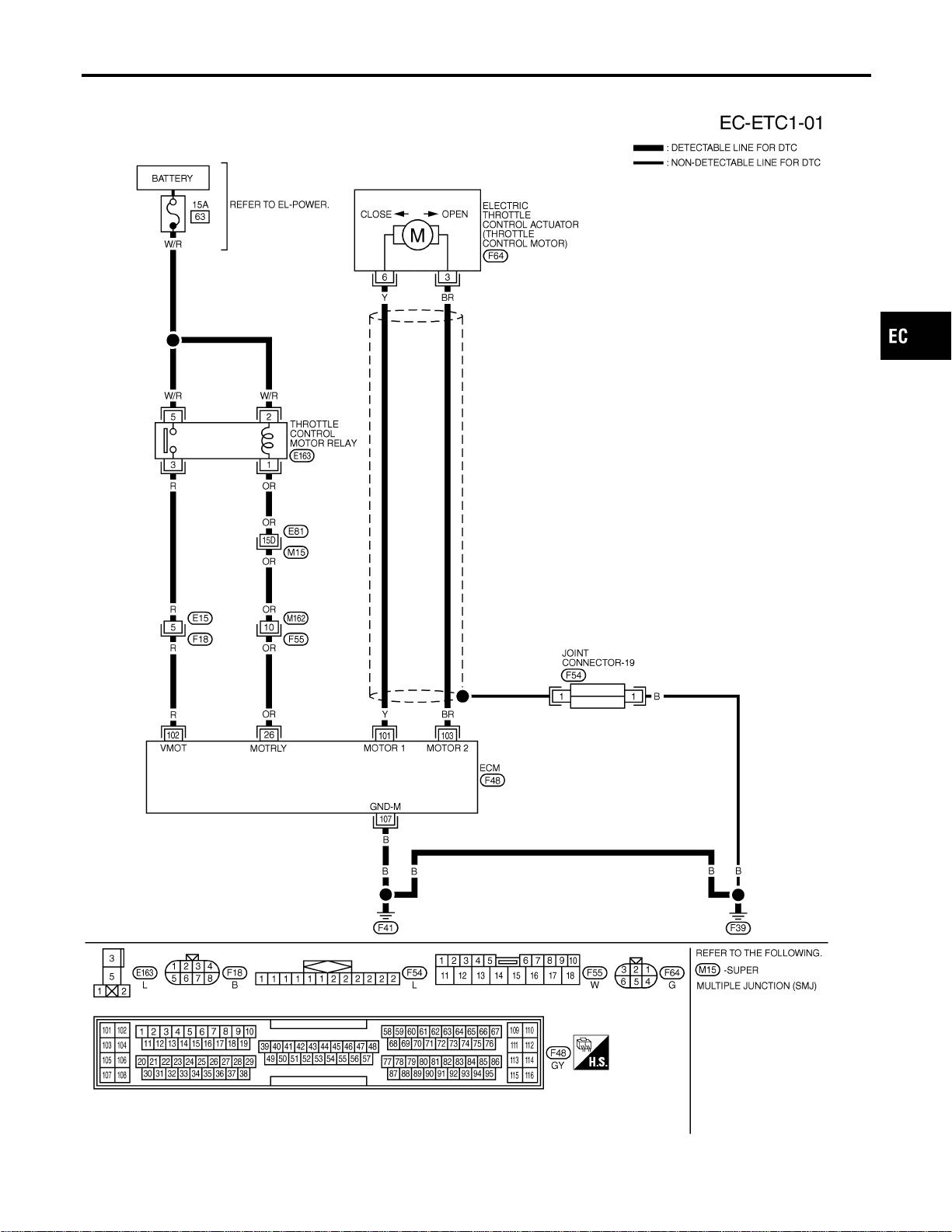
Wiring Diagram
NFEC1304
MEC478D
GI
MA
EM
LC
FE
CL
MT
AT
AX
SU
BR
ST
RS
BT
HA
SC
EL
IDX
DTC P1122 ELECTRIC THROTTLE CONTROL FUNCTION
Wiring Diagram
EC-475
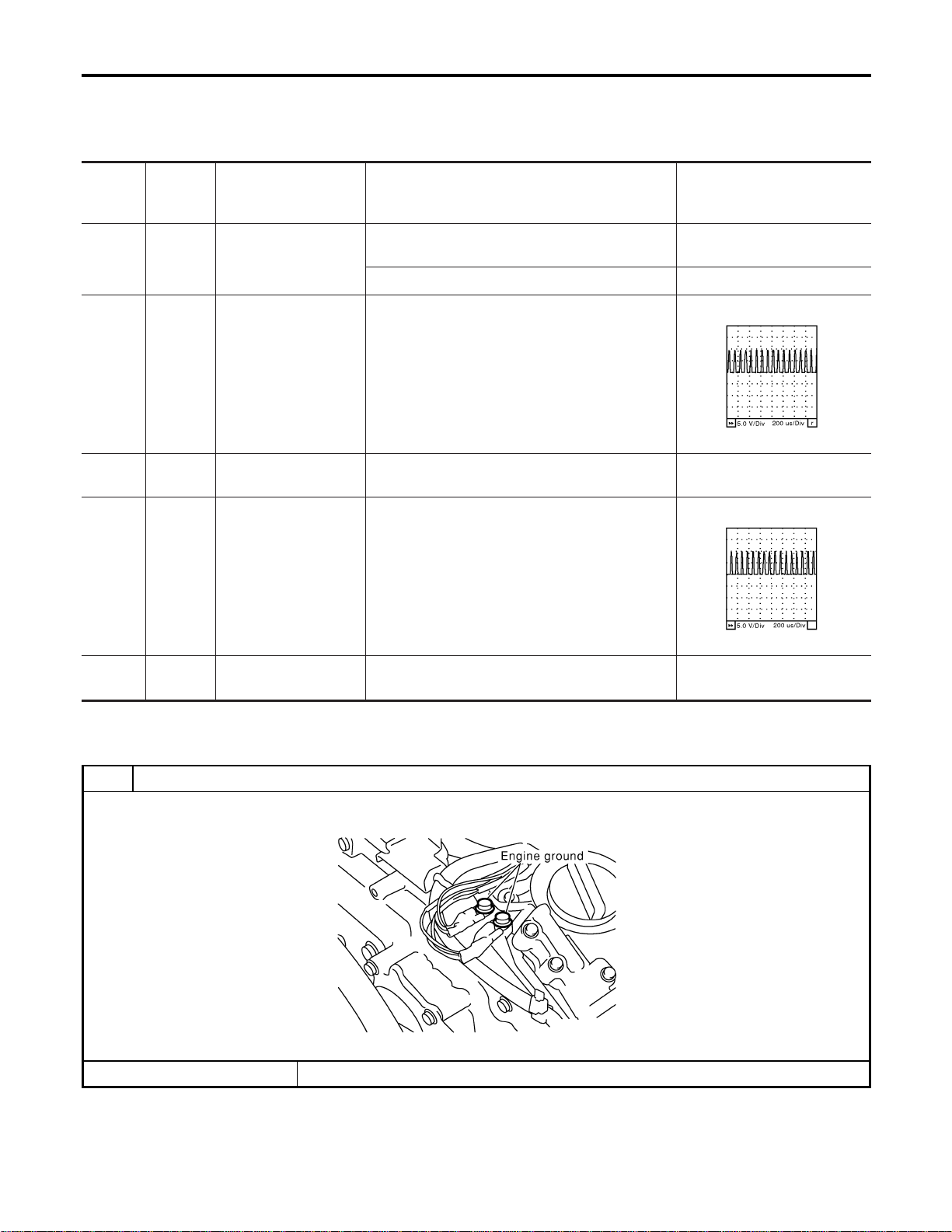
Specification data are reference values and are measured between each terminal and ground.
CAUTION:
Do not use ECM ground terminals when measuring input/output voltage. Doing so may result in dam-
age to the ECM’s transistor. Use a ground other than ECM terminals, such as the ground.
TERMI-
NAL
NO.
WIRE
COLOR
ITEM CONDITION DATA (DC Voltage)
26 OR
Throttle control motor
relay
[Ignition switch “OFF”]
BATTERY VOLTAGE
(11 - 14V)
[Ignition switch “ON”] 0 - 1.0V
101 Y
Throttle control motor
(Open)
[Ignition switch “ON”]
I Shift lever position is “D” (A/T model)
I Shift lever position is “1st” (M/T model)
I Accelerator pedal is depressing
0 - 14V★
SEC037D
102 R
Throttle control motor
relay power supply
[Ignition switch “ON”]
BATTERY VOLTAGE
(11 - 14V)
103 BR
Throttle control motor
(Close)
[Ignition switch “ON”]
I Shift lever position is “D” (A/T model)
I Shift lever position is “1st” (M/T model)
I Accelerator pedal is releasing
0 - 14V★
SEC038D
107 B
Throttle control motor
ground
[Engine is running]
I Idle speed
Approximately 0V
★: Average voltage for pulse signal (Actual pulse signal can be confirmed by oscilloscope.)
Diagnostic Procedure
NFEC1305
1 RETIGHTEN GROUND SCREWS
1. Turn ignition switch “OFF”.
2. Loosen and retighten engine ground screws.
SEC047D
© GO TO 2.
DTC P1122 ELECTRIC THROTTLE CONTROL FUNCTION
Wiring Diagram (Cont’d)
EC-476
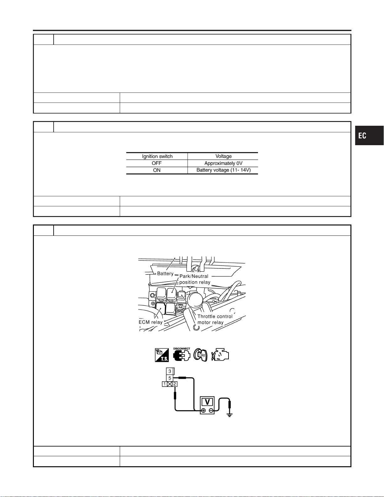
2 CHECK THROTTLE CONTROL MOTOR GROUND CIRCUIT FOR OPEN AND SHORT
1. Disconnect ECM harness connector.
2. Check harness continuity between ECM terminal 107 and engine ground.
Refer to Wiring Diagram.
Continuity should exist.
3. Also check harness for short to power.
OK or NG
OK © GO TO 3.
NG © Repair open circuit or short to power in harness or connectors.
3 CHECK THROTTLE CONTROL MOTOR RELAY INPUT SIGNAL CIRCUIT FOR OPEN AND SHORT-I
1. Reconnect harness connector disconnected.
2. Check voltage between ECM terminal 102 and ground under the following conditions with CONSULT-II or tester.
MTBL1168
OK or NG
OK © GO TO 12.
NG © GO TO 4.
4 CHECK THROTTLE CONTROL MOTOR RELAY POWER SUPPLY CIRCUIT
1. Turn ignition switch “OFF”.
2. Disconnect throttle control motor relay.
SEC044D
3. Check voltage between throttle control motor relay terminals 2, 5 and ground with CONSULT-II or tester.
SEC091D
Voltage: Battery voltage
OK or NG
OK © GO TO 6.
NG © GO TO 5.
GI
MA
EM
LC
FE
CL
MT
AT
AX
SU
BR
ST
RS
BT
HA
SC
EL
IDX
DTC P1122 ELECTRIC THROTTLE CONTROL FUNCTION
Diagnostic Procedure (Cont’d)
EC-477
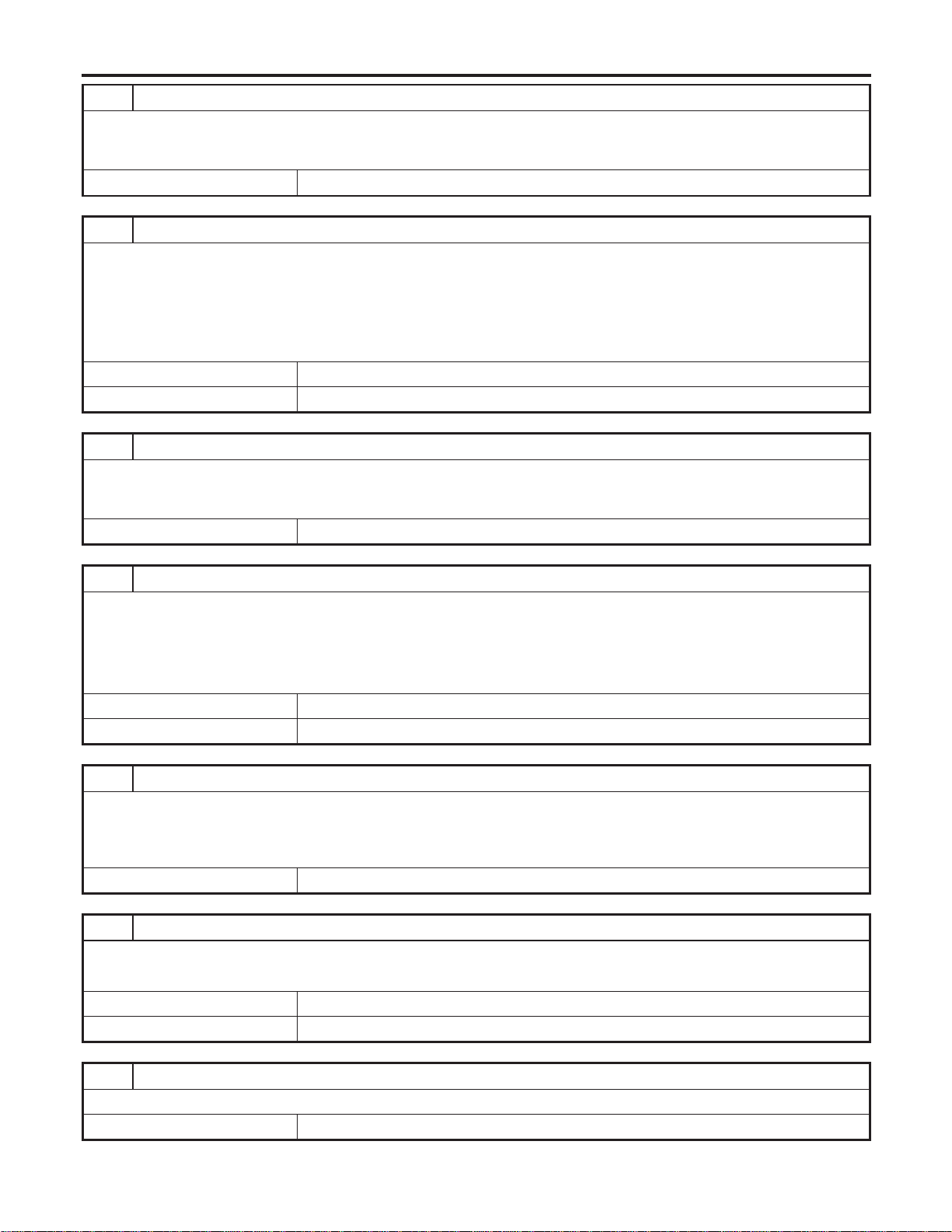
5 DETECT MALFUNCTIONING PART
Check the following.
I 15A fuse
I Harness for open and short between throttle control motor relay and fuse
© Repair open circuit or short to ground or short to power in harness or connectors.
6 CHECK THROTTLE CONTROL MOTOR RELAY INPUT SIGNAL CIRCUIT FOR OPEN AND SHORT-II
1. Disconnect ECM harness connector.
2. Check harness continuity between ECM terminal 102 and throttle control motor relay terminal 3.
Refer to Wiring Diagram.
Continuity should exist.
3. Also check harness for short to ground and short to power.
OK or NG
OK © GO TO 8.
NG © GO TO 7.
7 DETECT MALFUNCTIONING PART
Check the following.
I Harness connector E15, F18
I Harness for open and short between throttle control motor relay and ECM
© Repair open circuit or short to ground or short to power in harness or connectors.
8 CHECK THROTTLE CONTROL MOTOR RELAY OUTPUT SIGNAL CIRCUIT FOR OPEN AND SHORT
1. Check harness continuity between ECM terminal 26 and throttle control motor relay terminal 1.
Refer to Wiring Diagram.
Continuity should exist.
2. Also check harness for short to ground and short to power.
OK or NG
OK © GO TO 10.
NG © GO TO 9.
9 DETECT MALFUNCTIONING PART
Check the following.
I Harness connector E81, M15
I Harness connectors M162, F55
I Harness for open and short between throttle control motor relay and ECM
© Repair open circuit or short to ground or short to power in harness or connectors.
10 CHECK THROTTLE CONTROL MOTOR RELAY
Refer to “Component Inspection”, EC-480.
OK or NG
OK © GO TO 11.
NG © Replace throttle control motor relay.
11 CHECK INTERMITTENT INCIDENT
Perform “TROUBLE DIAGNOSIS FOR INTERMITTENT INCIDENT”, EC-156.
© INSPECTION END
DTC P1122 ELECTRIC THROTTLE CONTROL FUNCTION
Diagnostic Procedure (Cont’d)
EC-478
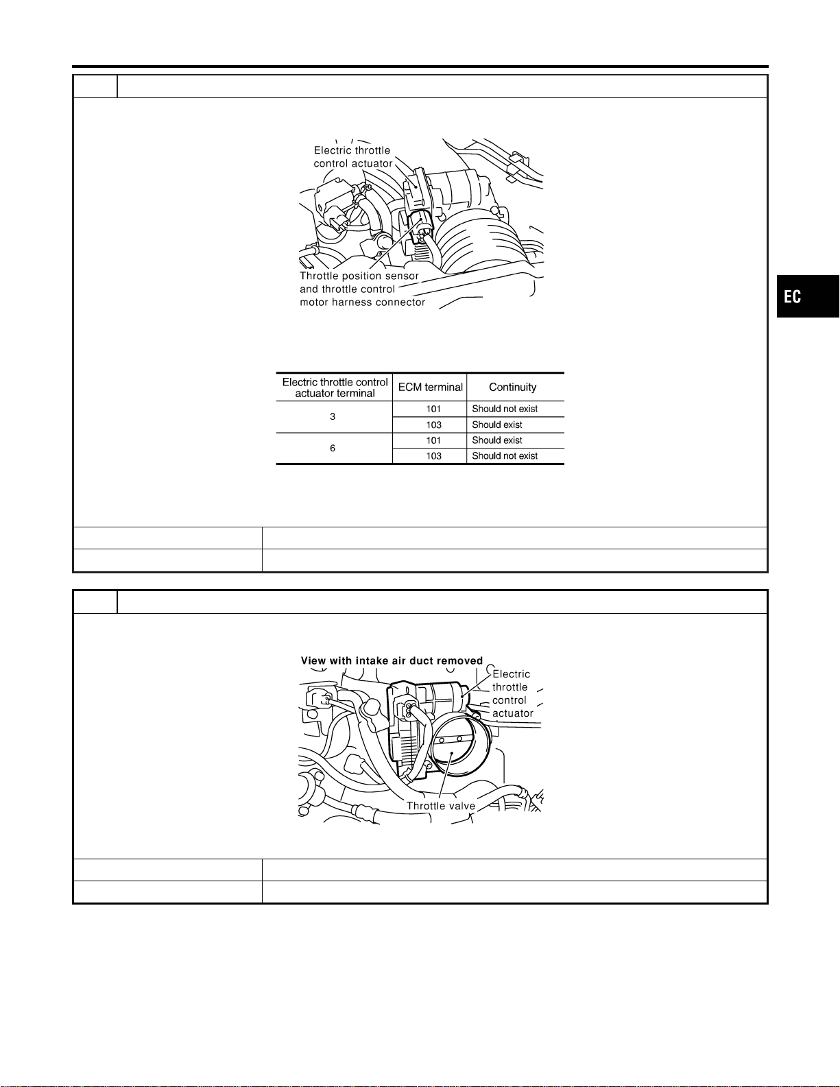
12 CHECK THROTTLE CONTROL MOTOR OUTPUT SIGNAL CIRCUIT FOR OPEN OR SHORT
1. Turn ignition switch “OFF”.
2. Disconnect electric throttle control actuator harness connector.
SEC054D
3. Disconnect ECM harness connector.
4. Check harness continuity between the following terminals.
Refer to Wiring Diagram.
MTBL1169
5. Also check harness for short to ground and short to power.
OK or NG
OK © GO TO 13.
NG © Repair or replace.
13 CHECK ELECTRIC THROTTLE CONTROL ACTUATOR VISUALLY
1. Remove the intake air duct.
2. Check if foreign matter is caught between the throttle valve and the housing.
SEC083D
OK or NG
OK © GO TO 14.
NG © Remove the foreign matter and clean the electric throttle control actuator inside.
GI
MA
EM
LC
FE
CL
MT
AT
AX
SU
BR
ST
RS
BT
HA
SC
EL
IDX
DTC P1122 ELECTRIC THROTTLE CONTROL FUNCTION
Diagnostic Procedure (Cont’d)
EC-479
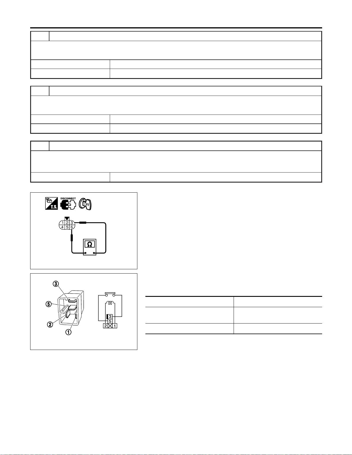
14 CHECK THROTTLE CONTROL MOTOR
Refer to “Component Inspection”, EC-480.
OK or NG
OK © GO TO 15.
NG © GO TO 16.
15 CHECK INTERMITTENT INCIDENT
Refer to “TROUBLE DIAGNOSIS FOR INTERMITTENT INCIDENT”, EC-156.
OK or NG
OK © GO TO 16.
NG © Repair or replace harness or connectors.
16 REPLACE ELECTRIC THROTTLE CONTROL ACTUATOR
1. Replace the electric throttle control actuator.
2. Perform “Throttle Valve Closed Position Learning”, EC-71.
3. Perform “Idle Air Volume Learning”, EC-71.
© INSPECTION END
PBIB0095E
Component Inspection
NFEC1306
THROTTLE CONTROL MOTOR
NFEC1306S01
1. Disconnect electric throttle control actuator harness connector.
2. Check resistance between terminals 3 and 6.
Resistance: Approximately1-15Ω [at 25°C (77°F)]
3. If NG, replace electric throttle control actuator and go to next
step.
4. Perform “Throttle Valve Closed Position Learning”, EC-71.
5. Perform “Idle Air Volume Learning”, EC-71.
PBIB0098E
THROTTLE CONTROL MOTOR RELAY
NFEC1306S02
1. Apply 12V direct current between relay terminals 1 and 2.
2. Check continuity between relay terminals 3 and 5.
Conditions Continuity
12V direct current supply between ter-
minals 1 and 2
Yes
No current supply No
3. If NG, replace throttle control motor relay.
DTC P1122 ELECTRIC THROTTLE CONTROL FUNCTION
Diagnostic Procedure (Cont’d)
EC-480
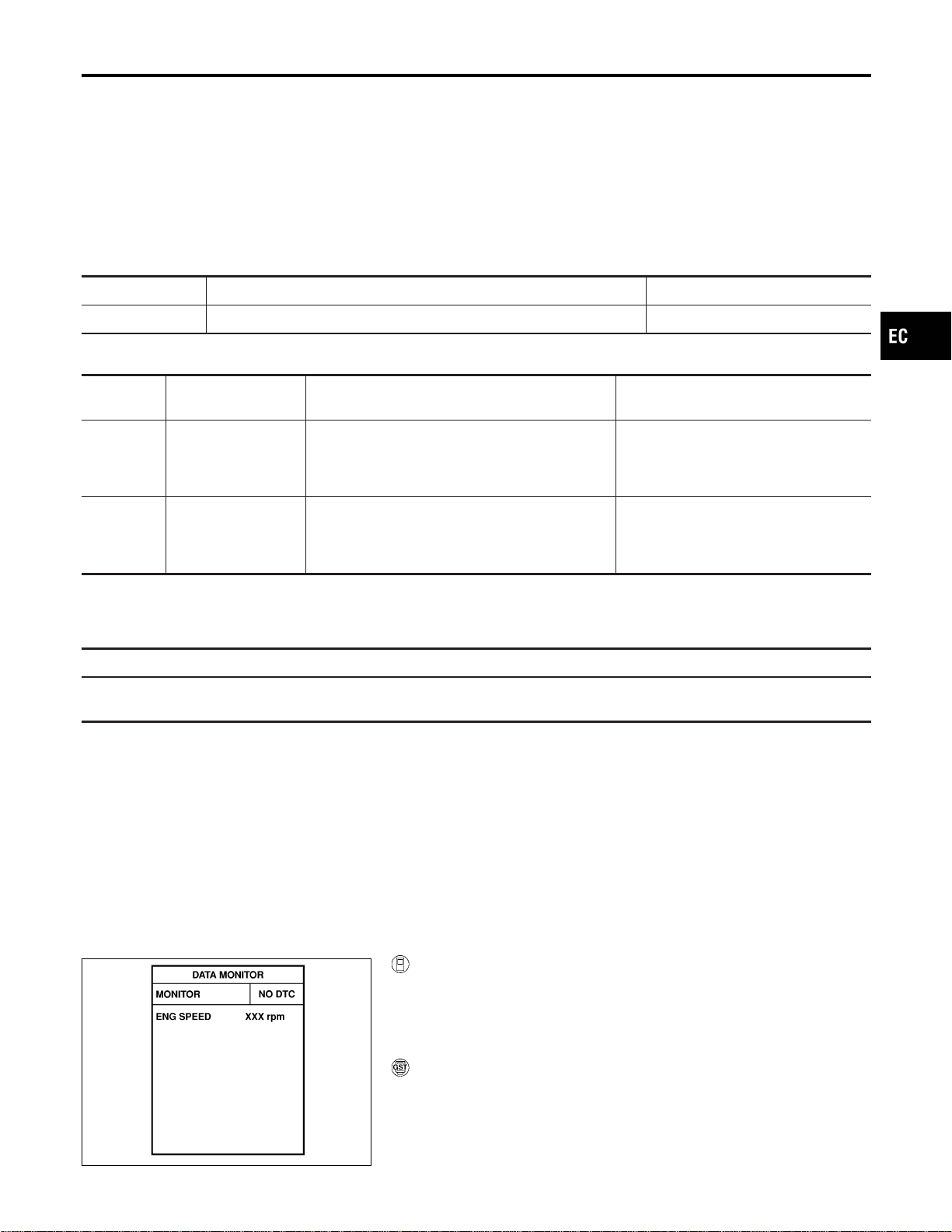
Component Description
NFEC1307
Power supply for the Throttle Control motor is provided to the ECM via throttle control motor relay. The throttle
control motor relay is ON/OFF controlled by the ECM. When the ignition switch is turned ON, the ECM sends
an ON signal to throttle control motor relay and battery voltage is provided to the ECM. When the ignition switch
is turned OFF, the ECM sends an OFF signal to throttle control motor relay and battery voltage is not pro-
vided to the ECM.
CONSULT-II Reference Value in Data Monitor
Mode
NFEC1319
Specification data are reference values.
MONITOR ITEM CONDITION SPECIFICATION
THRTL RELAY I Ignition switch: ON ON
On Board Diagnosis Logic
NFEC1450
DTC No.
Trouble diagnosis
name
DTC Detecting Condition Possible Cause
P1124
1124
Throttle control motor
relay circuit short
ECM detect the throttle control motor relay is stuck
ON.
I Harness or connectors
(Throttle control motor relay circuit is
shorted)
I Throttle control motor relay
P1126
1126
Throttle control motor
relay circuit open
ECM detects a voltage of power source for throttle
control motor is excessively low.
This self-diagnosis has the one trip detection
logic.
I Harness or connectors
(Throttle control motor relay circuit is
open)
I Throttle control motor relay
FAIL-SAFE MODE
NFEC1450S01
When the malfunction is detected, ECM enters in fail-safe mode (for DTC P1124).
When the malfunction is detected, ECM enters in fail-safe mode and the MIL lights up (for DTC P1126).
Engine operating condition in fail-safe mode
ECM stops the electric throttle control actuator control, throttle valve is maintained at a fixed opening (approx. 5 degrees) by the
return spring.
DTC Confirmation Procedure
NFEC1451
NOTE:
If “DTC Confirmation Procedure” has been previously conducted,
always turn ignition switch “OFF” and wait at least 10 seconds
before conducting the next test.
PROCEDURE FOR DTC P1124
TESTING CONDITION:
Before performing the following procedure, confirm that bat-
tery voltage is more than 10V at idle.
SEF058Y
With CONSULT-II
1) Turn ignition switch “ON” and wait at least 1 second.
2) Select “DATA MONITOR” mode with CONSULT-II.
3) If 1st trip DTC is detected, go to “Diagnostic Procedure”,
EC-484.
With GST
Follow the procedure “With CONSULT-II” above.
GI
MA
EM
LC
FE
CL
MT
AT
AX
SU
BR
ST
RS
BT
HA
SC
EL
IDX
DTC P1124, P1126 THROTTLE CONTROL MOTOR RELAY
Component Description
EC-481
SEF058Y
PROCEDURE FOR DTC P1126
With CONSULT-II
1) Turn ignition switch “ON” and wait at least 2 seconds.
2) Select “DATA MONITOR” mode with CONSULT-II.
3) Start engine and let it idle for 5 seconds.
4) If DTC is detected, go to “Diagnostic Procedure”, EC-484.
With GST
Follow the procedure “With CONSULT-II” above.
DTC P1124, P1126 THROTTLE CONTROL MOTOR RELAY
DTC Confirmation Procedure (Cont’d)
EC-482
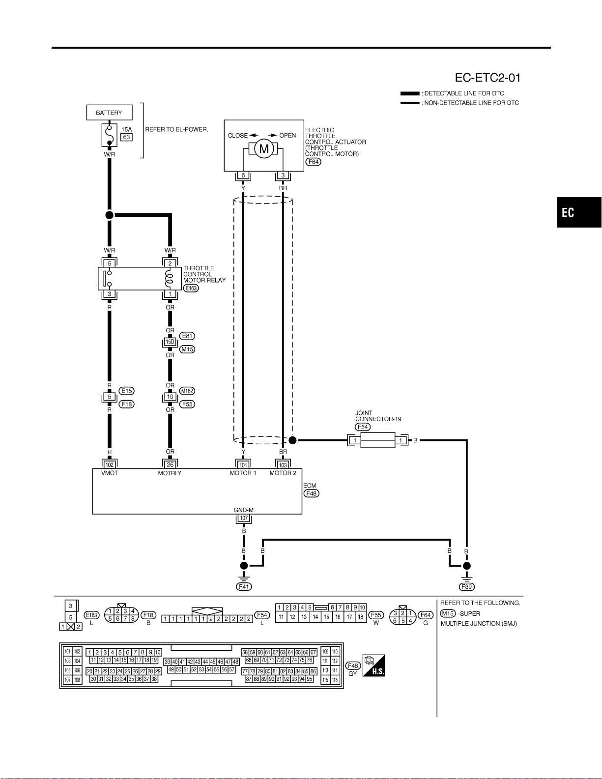
Wiring Diagram
NFEC1310
MEC654D
GI
MA
EM
LC
FE
CL
MT
AT
AX
SU
BR
ST
RS
BT
HA
SC
EL
IDX
DTC P1124, P1126 THROTTLE CONTROL MOTOR RELAY
Wiring Diagram
EC-483
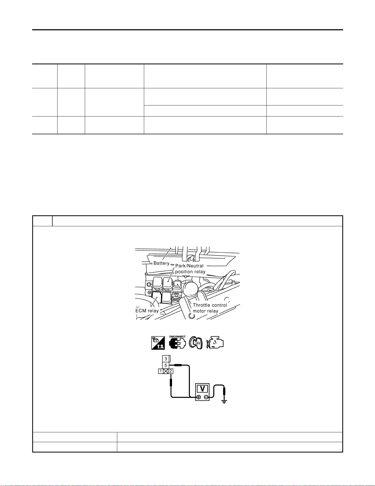
Specification data are reference values and are measured between each terminal and ground.
CAUTION:
Do not use ECM ground terminals when measuring input/output voltage. Doing so may result in dam-
age to the ECM’s transistor. Use a ground other than ECM terminals, such as the ground.
TERMI-
NAL
NO.
WIRE
COLOR
ITEM CONDITION DATA (DC Voltage)
26 OR
Throttle control motor
relay
[Ignition switch “OFF”]
BATTERY VOLTAGE
(11 - 14V)
[Ignition switch “ON”] 0 - 1.0V
102 R
Throttle control motor
relay power supply
[Ignition switch “ON”]
BATTERY VOLTAGE
(11 - 14V)
Diagnostic Procedure
NFEC1311
1 CHECK THROTTLE CONTROL MOTOR RELAY POWER SUPPLY CIRCUIT
1. Turn ignition switch “OFF”.
2. Disconnect throttle control motor relay.
SEC044D
3. Check voltage between throttle control motor relay terminals 2, 5 and ground with CONSULT-II or tester.
SEC091D
Voltage: Battery voltage
OK or NG
OK © GO TO 3.
NG © GO TO 2.
DTC P1124, P1126 THROTTLE CONTROL MOTOR RELAY
Wiring Diagram (Cont’d)
EC-484
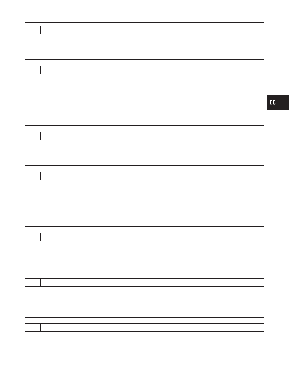
2 DETECT MALFUNCTIONING PART
Check the following.
I 15A fuse
I Harness for open and short between throttle control motor relay and fuse
© Repair open circuit or short to ground or short to power in harness or connectors.
3 CHECK THROTTLE CONTROL MOTOR RELAY INPUT SIGNAL CIRCUIT FOR OPEN AND SHORT
1. Disconnect ECM harness connector.
2. Check harness continuity between ECM terminal 102 and throttle control motor relay terminal 3.
Refer to Wiring Diagram.
Continuity should exist.
3. Also check harness for short to ground and short to power.
OK or NG
OK © GO TO 5.
NG © GO TO 4.
4 DETECT MALFUNCTIONING PART
Check the following.
I Harness connector E15, F18
I Harness for open and short between throttle control motor relay and ECM
© Repair open circuit or short to ground or short to power in harness or connectors.
5 CHECK THROTTLE CONTROL MOTOR RELAY OUTPUT SIGNAL CIRCUIT FOR OPEN AND SHORT
1. Check harness continuity between ECM terminal 26 and throttle control motor relay terminal 1.
Refer to Wiring Diagram.
Continuity should exist.
2. Also check harness for short to ground and short to power.
OK or NG
OK © GO TO 7.
NG © GO TO 6.
6 DETECT MALFUNCTIONING PART
Check the following.
I Harness connector E81, M15
I Harness connectors M162, F55
I Harness for open and short between throttle control motor relay and ECM
© Repair open circuit or short to ground or short to power in harness or connectors.
7 CHECK THROTTLE CONTROL MOTOR RELAY
Refer to “Component Inspection”, EC-486.
OK or NG
OK © GO TO 8.
NG © Replace throttle control motor relay.
8 CHECK INTERMITTENT INCIDENT
Refer to “TROUBLE DIAGNOSIS FOR INTERMITTENT INCIDENT”, EC-156.
© INSPECTION END
GI
MA
EM
LC
FE
CL
MT
AT
AX
SU
BR
ST
RS
BT
HA
SC
EL
IDX
DTC P1124, P1126 THROTTLE CONTROL MOTOR RELAY
Diagnostic Procedure (Cont’d)
EC-485
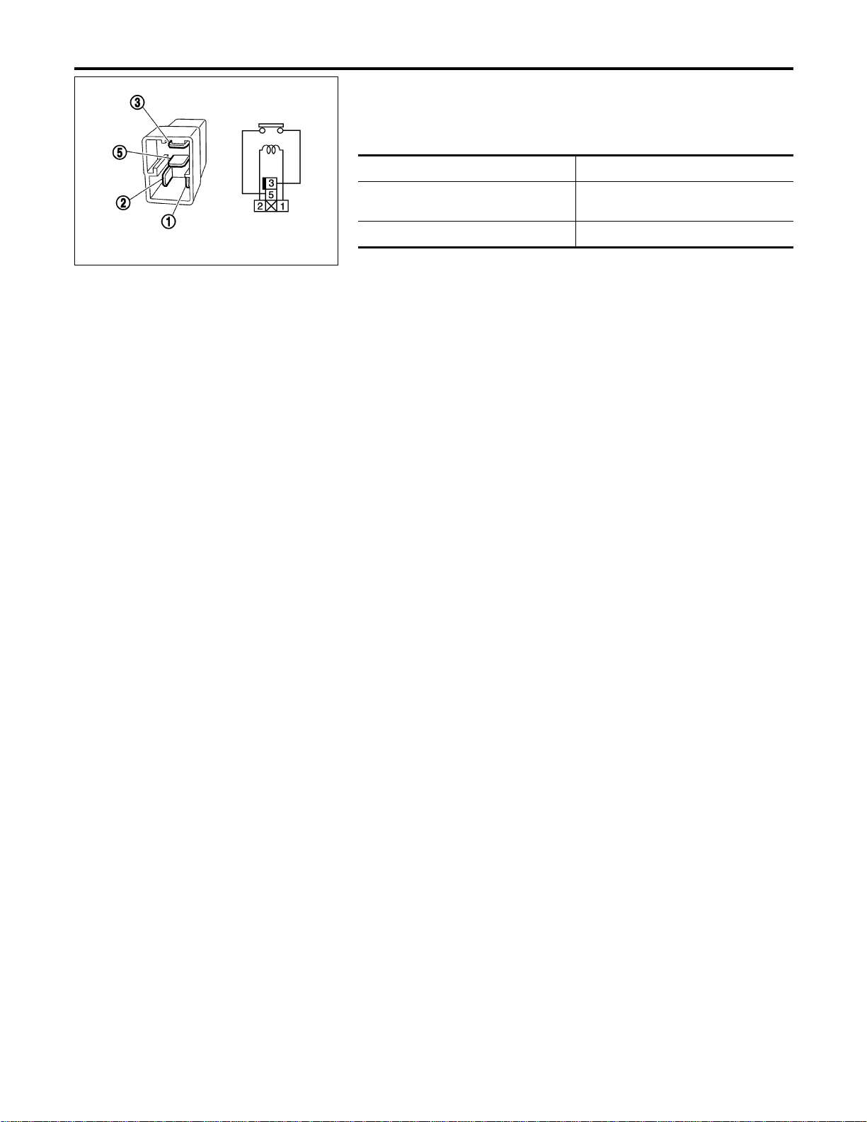
PBIB0098E
Component Inspection
NFEC1312
THROTTLE CONTROL MOTOR RELAY
1. Apply 12V direct current between relay terminals 1 and 2.
2. Check continuity between relay terminals 3 and 5.
Conditions Continuity
12V direct current supply between ter-
minals 1 and 2
Yes
No current supply No
3. If NG, replace throttle control motor relay.
DTC P1124, P1126 THROTTLE CONTROL MOTOR RELAY
Component Inspection
EC-486
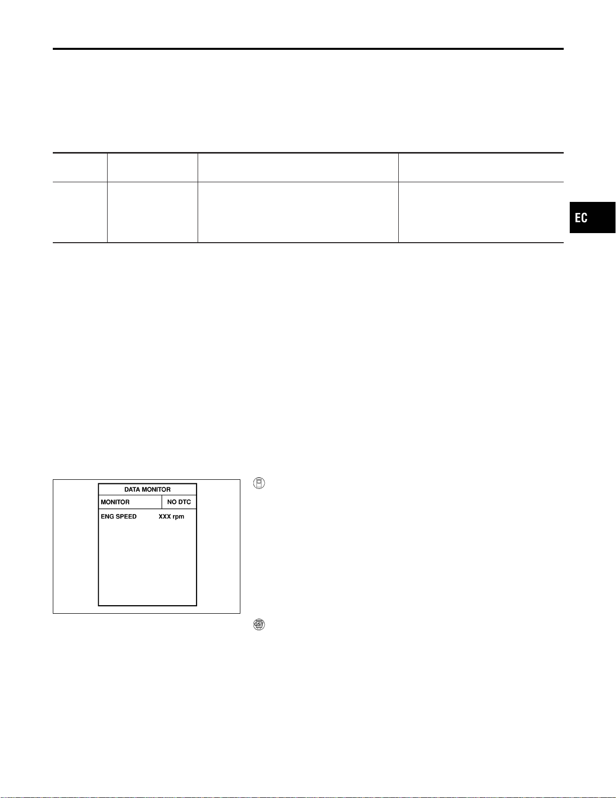
Component Description
NFEC1313
The throttle control motor is operated by the ECM and it opens and closes the throttle valve.
The current opening angle of the throttle valve is detected by the throttle position sensor and it provides feed-
back to the ECM to control the throttle control motor to make the throttle valve opening angle properly in
response to driving condition.
On Board Diagnosis Logic
NFEC1452
This self-diagnosis has the one trip detection logic.
DTC No.
Trouble diagnosis
name
DTC Detecting Condition Possible Cause
P1128
1128
Throttle control motor
circuit short
ECM detects short both circuits between ECM and
throttle control motor.
I Harness or connectors
(Throttle control motor circuit is
shorted.)
I Electric throttle control actuator
(Throttle control motor)
DTC Confirmation Procedure
NFEC1453
NOTE:
If “DTC Confirmation Procedure” has been previously conducted,
always turn ignition switch “OFF” and wait at least 10 seconds
before conducting the next test.
SEF058Y
With CONSULT-II
1) Turn ignition switch “ON” and wait at least 2 seconds.
2) Select “DATA MONITOR” mode with CONSULT-II.
3) Start engine and let it idle for 5 seconds.
4) If DTC is detected, go to “Diagnostic Procedure”, EC-489.
With GST
Follow the procedure “With CONSULT-II” above.
GI
MA
EM
LC
FE
CL
MT
AT
AX
SU
BR
ST
RS
BT
HA
SC
EL
IDX
DTC P1128 THROTTLE CONTROL MOTOR
Component Description
EC-487
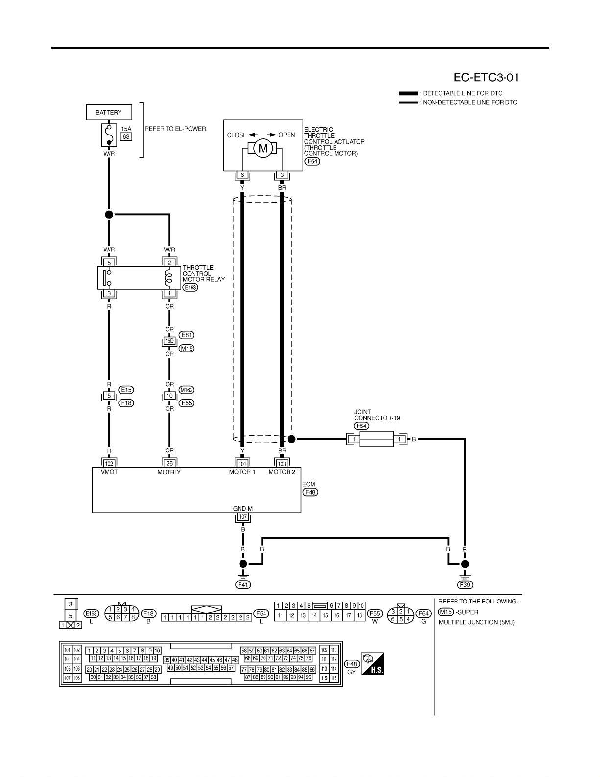
Wiring Diagram
NFEC1316
MEC655D
DTC P1128 THROTTLE CONTROL MOTOR
Wiring Diagram
EC-488
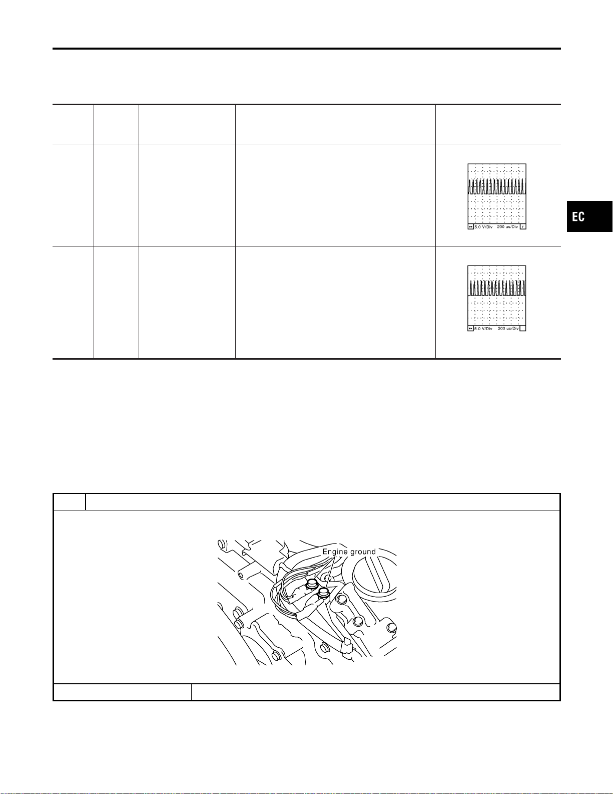
Specification data are reference values and are measured between each terminal and ground.
CAUTION:
Do not use ECM ground terminals when measuring input/output voltage. Doing so may result in dam-
age to the ECM’s transistor. Use a ground other than ECM terminals, such as the ground.
TERMI-
NAL
NO.
WIRE
COLOR
ITEM CONDITION DATA (DC Voltage)
101 Y
Throttle control motor
(Open)
[Ignition switch “ON”]
I Shift lever position is “D” (A/T model)
I Shift lever position is “1st” (M/T model)
I Accelerator pedal is depressing
0-5V★
SEC037D
103 BR
Throttle control motor
(Close)
[Ignition switch “ON”]
I Shift lever position is “D” (A/T model)
I Shift lever position is “1st” (M/T model)
I Accelerator pedal is releasing
0-3V★
SEC038D
★: Average voltage for pulse signal (Actual pulse signal can be confirmed by oscilloscope.)
Diagnostic Procedure
NFEC1317
1 RETIGHTEN GROUND SCREWS
1. Turn ignition switch “OFF”.
2. Loosen and retighten engine ground screws.
SEC047D
© GO TO 2.
GI
MA
EM
LC
FE
CL
MT
AT
AX
SU
BR
ST
RS
BT
HA
SC
EL
IDX
DTC P1128 THROTTLE CONTROL MOTOR
Wiring Diagram (Cont’d)
EC-489

2 CHECK THROTTLE CONTROL MOTOR OUTPUT SIGNAL CIRCUIT FOR OPEN OR SHORT
1. Turn ignition switch “OFF”.
2. Disconnect electric throttle control actuator harness connector.
3. Disconnect ECM harness connector.
4. Check harness continuity between the following terminals.
Refer to Wiring Diagram.
SEC054D
MTBL1169
5. Also check harness for short to ground and short to power.
OK or NG
OK © GO TO 3.
NG © Repair or replace.
3 CHECK THROTTLE CONTROL MOTOR
Refer to “Component Inspection”, EC-491.
OK or NG
OK © GO TO 4.
NG © GO TO 5.
4 CHECK INTERMITTENT INCIDENT
Refer to “TROUBLE DIAGNOSIS FOR INTERMITTENT INCIDENT”, EC-156.
OK or NG
OK © GO TO 5.
NG © Repair or replace harness or connectors.
5 REPLACE ELECTRIC THROTTLE CONTROL ACTUATOR
1. Replace the electric throttle control actuator.
2. Perform “Throttle Valve Closed Position Learning”, EC-71.
3. Perform “Idle Air Volume Learning”, EC-71.
© INSPECTION END
DTC P1128 THROTTLE CONTROL MOTOR
Diagnostic Procedure (Cont’d)
EC-490
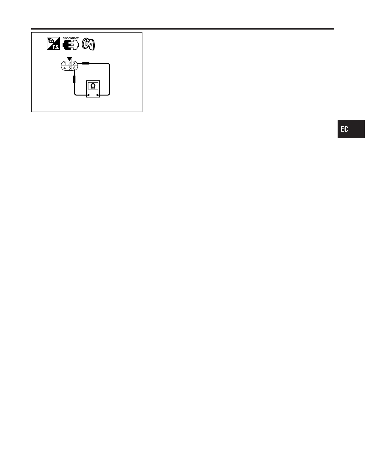
PBIB0095E
Component Inspection
NFEC1318
THROTTLE CONTROL MOTOR
1. Disconnect electric throttle control actuator harness connector.
2. Check resistance between terminals 3 and 6.
Resistance: Approximately1-15Ω [at 25°C (77°F)]
3. If NG, replace electric throttle control actuator and go to next
step.
4. Perform “Throttle Valve Closed Position Learning”, EC-71.
5. Perform “Idle Air Volume Learning”, EC-71.
GI
MA
EM
LC
FE
CL
MT
AT
AX
SU
BR
ST
RS
BT
HA
SC
EL
IDX
DTC P1128 THROTTLE CONTROL MOTOR
Component Inspection
EC-491
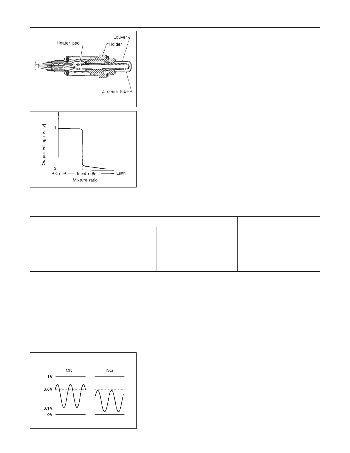
SEF463R
SEF288D
Component Description
NFEC1147
The heated oxygen sensor 1 is placed into the front tube. It detects
the amount of oxygen in the exhaust gas compared to the outside
air. The heated oxygen sensor 1 has a closed-end tube made of
ceramic zirconia. The zirconia generates voltage from approxi-
mately 1V in richer conditions to 0V in leaner conditions. The
heated oxygen sensor 1 signal is sent to the ECM. The ECM
adjusts the injection pulse duration to achieve the ideal air-fuel
ratio. The ideal air-fuel ratio occurs near the radical change from
1V to 0V.
CONSULT-II Reference Value in Data Monitor
Mode
NFEC1148
Specification data are reference values.
MONITOR ITEM CONDITION SPECIFICATION
HO2S1 (B1)
HO2S1 (B2)
I Engine: After warming up
Maintaining engine speed at 2,000
rpm
0 - 0.3V +, Approx. 0.6 - 1.0V
HO2S1 MNTR
(B1)
HO2S1 MNTR
(B2)
LEAN +, RICH
Changes more than 5 times during
10 seconds.
SEF300U
On Board Diagnosis Logic
NFEC1150
To judge the malfunction, the output from the heated oxygen sen-
sor 1 is monitored to determine whether the “rich” output is suffi-
ciently high and whether the “lean” output is sufficiently low. When
both the outputs are shifting to the lean side, the malfunction will
be detected.
DTC P1143, P1163 HO2S1
Component Description
EC-492
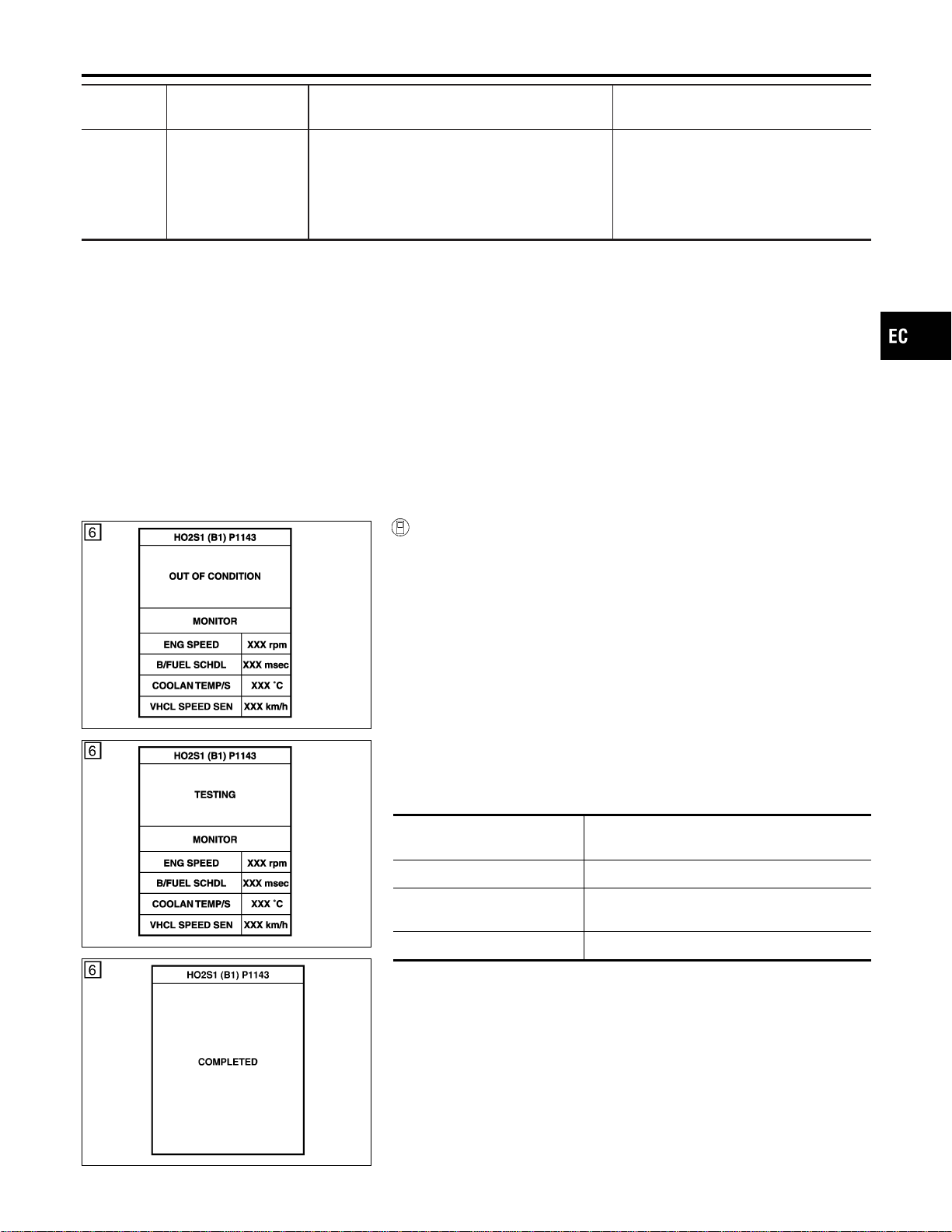
DTC No.
Trouble diagnosis
name
DTC Detecting Condition Possible Cause
P1143
1143
(Bank 1)
P1163
1163
(Bank 2)
Heated oxygen sen-
sor 1 lean shift moni-
toring
The maximum and minimum voltage from the
sensor are not reached to the specified voltages.
I Heated oxygen sensor 1
I Heated oxygen sensor 1 heater
I Fuel pressure
I Injectors
I Intake air leaks
DTC Confirmation Procedure
NFEC1151
CAUTION:
Always drive vehicle at a safe speed.
NOTE:
If “DTC Confirmation Procedure” has been previously conducted,
always turn ignition switch “OFF” and wait at least 10 seconds
before conducting the next test.
TESTING CONDITION:
I Always perform at a temperature above −10°C (14°F).
I Before performing following procedure, confirm that bat-
tery voltage is more than 11V at idle.
PBIB0546E
PBIB0547E
SEC769C
WITH CONSULT-II
NFEC1151S01
1) Start engine and warm it up to normal operating temperature.
2) Stop engine and wait at least 10 seconds.
3) Turn ignition switch “ON” and select “HO2S1 (B1)/(B2) P1143/
P1163” of “HO2S1” in “DTC WORK SUPPORT” mode with
CONSULT-II.
4) Touch “START”.
5) Start engine and let it idle for at least 3 minutes.
NOTE:
Never raise engine speed above 3,600 rpm after this step. If
the engine speed limit is exceeded, return to step 5.
6) When the following conditions are met, “TESTING” will be dis-
played on the CONSULT-II screen. Maintain the conditions
continuously until “TESTING” changes to “COMPLETED”. (It
will take approximately 50 seconds or more.)
ENG SPEED 1,200 - 2,600 rpm (A/T)
1,800 - 2,600 rpm (M/T)
Vehicle speed Less than 100 km/h (62 MPH)
B/FUEL SCHDL 3 - 9 msec (A/T)
2.5 - 9 msec (M/T)
Selector lever Suitable position
If “TESTING” is not displayed after 5 minutes, retry from
step 2.
7) Make sure that “OK” is displayed after touching “SELF-DIAG
RESULTS”. If “NG” is displayed, refer to “Diagnostic
Procedure”, EC-494.
GI
MA
EM
LC
FE
CL
MT
AT
AX
SU
BR
ST
RS
BT
HA
SC
EL
IDX
DTC P1143, P1163 HO2S1
On Board Diagnosis Logic (Cont’d)
EC-493
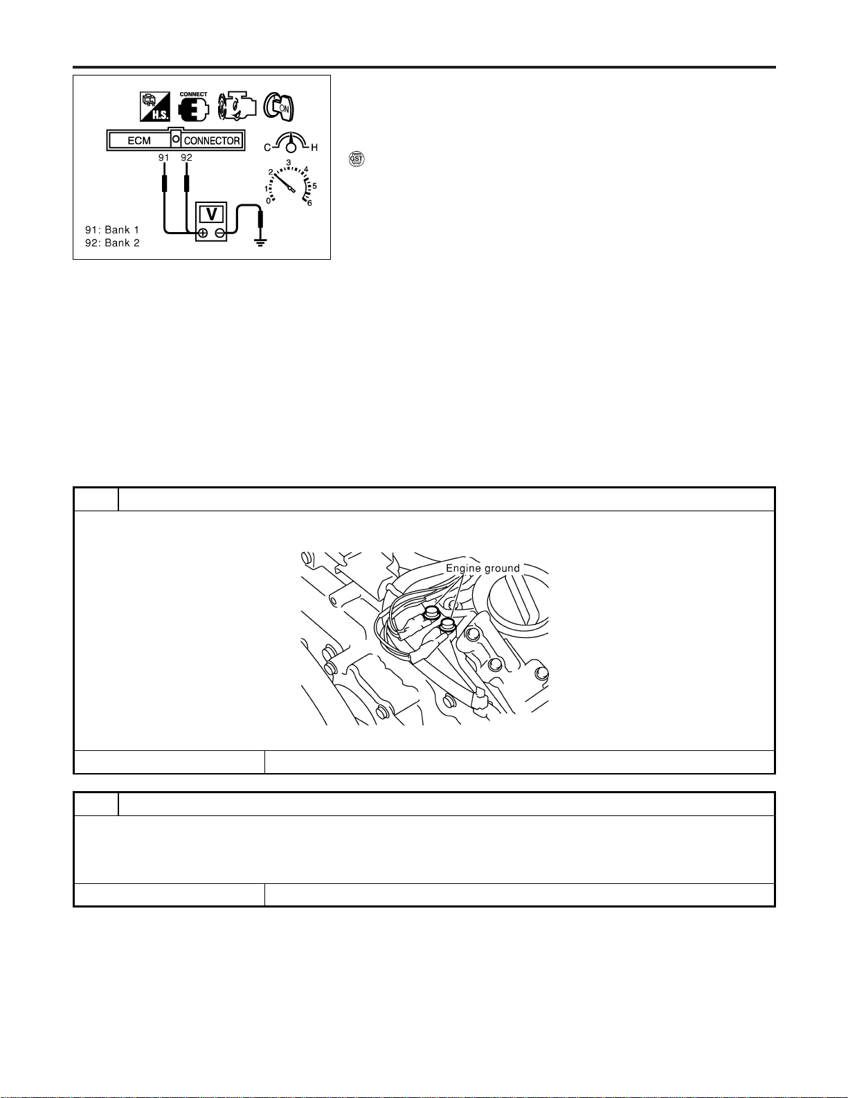
SEC902C
Overall Function Check
NFEC1152
Use this procedure to check the overall function of the heated oxy-
gen sensor 1 circuit. During this check, a DTC might not be con-
firmed.
WITH GST
NFEC1152S01
1) Start engine and warm it up to normal operating temperature.
2) Set voltmeter probes between ECM terminal 91 (bank 1
HO2S1 signal) or 92 (bank 2 HO2S1 signal) and engine
ground.
3) Check one of the following with engine speed held at 2,000
rpm constant under no load.
I The maximum voltage is over 0.6V at least one time.
I The minimum voltage is over 0.1V at least one time.
4) If NG, go to “Diagnostic Procedure”, EC-494.
Diagnostic Procedure
NFEC1153
1 RETIGHTEN GROUND SCREWS
1. Turn ignition switch “OFF”.
2. Loosen and retighten engine ground screws.
SEC047D
© GO TO 2.
2 RETIGHTEN HEATED OXYGEN SENSOR 1
Loosen and retighten corresponding heated oxygen sensor 1.
Tightening torque:
40 - 60 N·m (4.1 - 6.1 kg-m, 30 - 44 ft-lb)
© GO TO 3.
DTC P1143, P1163 HO2S1
Overall Function Check
EC-494
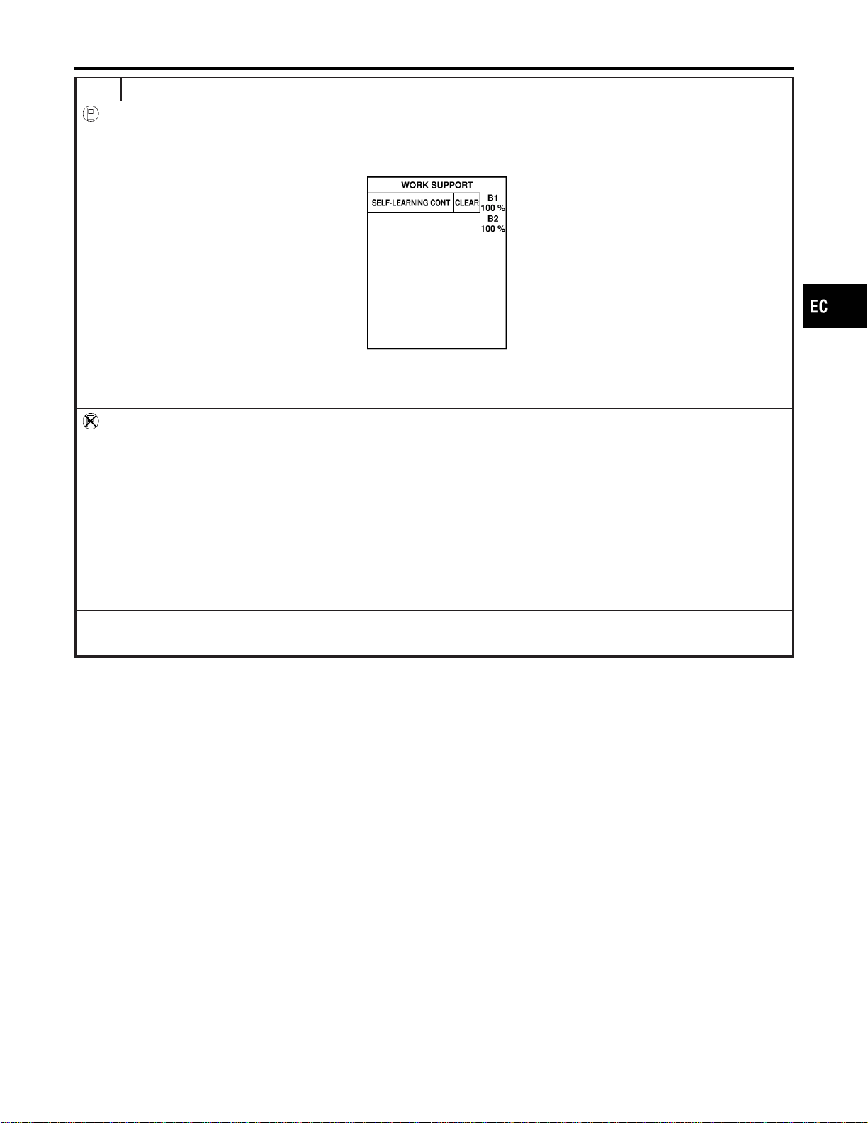
3 CLEAR THE SELF-LEARNING DATA
With CONSULT-II
1. Start engine and warm it up to normal operating temperature.
2. Select “SELF-LEARNING CONT” in “WORK SUPPORT” mode with CONSULT-II.
3. Clear the self-learning control coefficient by touching “CLEAR”.
SEF968Y
4. Run engine for at least 10 minutes at idle speed.
Is the 1st trip DTC P0171 or P0174 detected?
Is it difficult to start engine?
Without CONSULT-II
1. Start engine and warm it up to normal operating temperature.
2. Turn ignition switch “OFF”.
3. Disconnect mass air flow sensor harness connector, and restart and run engine for at least 5 seconds at idle speed.
4. Stop engine and reconnect mass air flow sensor harness connector.
5. Make sure DTC P0102 is displayed.
6. Erase the DTC memory. Refer to “HOW TO ERASE EMISSION-RELATED DIAGNOSTIC INFORMATION”, EC-91.
7. Make sure DTC P0000 is displayed.
8. Run engine for at least 10 minutes at idle speed.
Is the 1st trip DTC P0171 or P0174 detected?
Is it difficult to start engine?
YesorNo
Yes © Perform trouble diagnosis for DTC P0171, P0174. Refer to EC-267.
No © GO TO 4.
GI
MA
EM
LC
FE
CL
MT
AT
AX
SU
BR
ST
RS
BT
HA
SC
EL
IDX
DTC P1143, P1163 HO2S1
Diagnostic Procedure (Cont’d)
EC-495
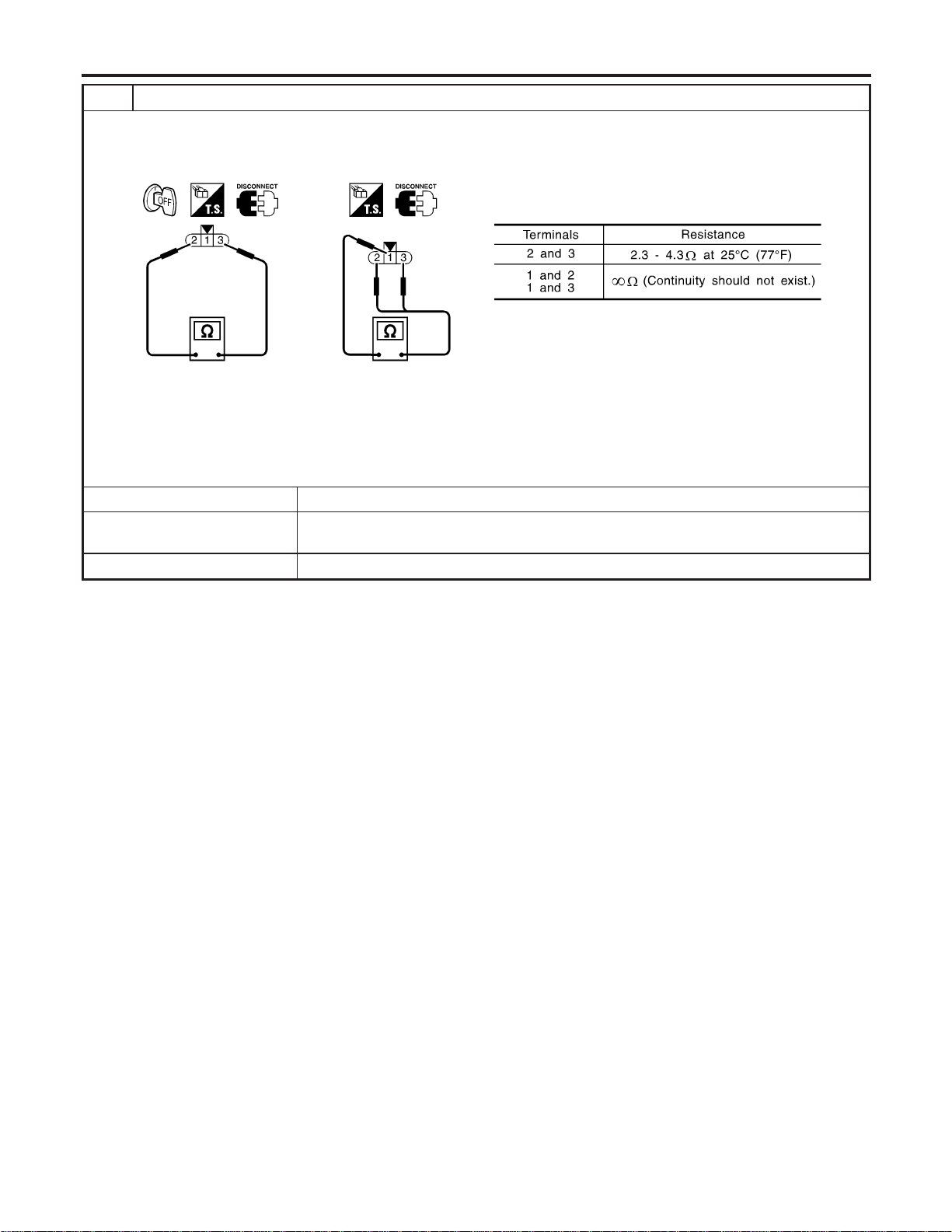
4 CHECK HEATED OXYGEN SENSOR 1 HEATER
1. Stop engine.
2. Disconnect HO2S1 harness connector.
3. Check resistance between HO2S1 terminals as follows.
SEF310X
CAUTION:
I Discard any heated oxygen sensor which has been dropped from a height of more than 0.5 m (19.7 in) onto a
hard surface such as a concrete floor; use a new one.
I Before installing new oxygen sensor, clean exhaust system threads using Oxygen Sensor Thread Cleaner tool
J-43897-18 or J-43897-12 and approved anti-seize lubricant.
OK or NG
OK (With CONSULT-II) © GO TO 5.
OK (Without CONSULT-
II)
© GO TO 6.
NG © Replace malfunctioning heated oxygen sensor 1.
DTC P1143, P1163 HO2S1
Diagnostic Procedure (Cont’d)
EC-496

5 CHECK HEATED OXYGEN SENSOR 1
With CONSULT-II
1. Start engine and warm it up to normal operating temperature.
2. Select “MANU TRIG” and adjust “TRIGGER POINT” to 100% in “DATA MONITOR” mode with CONSULT-II.
3. Select “HO2S1 (B1)/(B2)” and “HO2S1 MNTR (B1)/(B2)”.
4. Hold engine speed at 2,000 rpm under no load during the following steps.
5. Touch “RECORD” on CONSULT-II screen.
SEF967Y
6. Check the following.
I “HO2S1 MNTR (B1)/(B2)” in “DATA MONITOR” mode changes from “RICH” to “LEAN” to “RICH” 5 times in 10 seconds.
5 times (cycles) are counted as shown below.
SEF647Y
I “HO2S1 (B1)/(B2)” voltage goes above 0.6V at least once.
I “HO2S1 (B1)/(B2)” voltage goes below 0.3V at least once.
I “HO2S1 (B1)/(B2)” voltage never exceeds 1.0V.
SEF648Y
CAUTION:
I Discard any heated oxygen sensor which has been dropped from a height of more than 0.5 m (19.7 in) onto a
hard surface such as a concrete floor; use a new one.
I Before installing new oxygen sensor, clean exhaust system threads using Oxygen Sensor Thread Cleaner tool
J-43897-18 or J-43897-12 and approved anti-seize lubricant.
OK or NG
OK © GO TO 7.
NG © Replace malfunctioning heated oxygen sensor 1.
GI
MA
EM
LC
FE
CL
MT
AT
AX
SU
BR
ST
RS
BT
HA
SC
EL
IDX
DTC P1143, P1163 HO2S1
Diagnostic Procedure (Cont’d)
EC-497
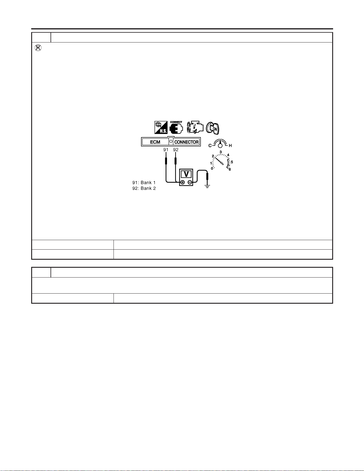
6 CHECK HEATED OXYGEN SENSOR 1
Without CONSULT-II
1. Start engine and warm it up to normal operating temperature.
2. Set voltmeter probes between ECM terminal 91 (HO2S1 bank 1 signal) or 92 (HO2S1 bank 2 signal) and engine
ground.
3. Check the following with engine speed held at 2,000 rpm constant under no load.
I The voltage fluctuates between 0 to 0.3V and 0.6 to 1.0V more than 5 times within 10 seconds.
I The maximum voltage is over 0.6V at least one time.
I The minimum voltage is below 0.3V at least one time.
I The voltage never exceeds 1.0V.
1 time: 0 - 0.3V , 0.6 - 1.0V , 0 - 0.3V
2 times: 0 - 0.3V , 0.6 - 1.0V , 0 - 0.3V , 0.6 - 1.0V , 0 - 0.3V
SEC085D
CAUTION:
I Discard any heated oxygen sensor which has been dropped from a height of more than 0.5 m (19.7 in) onto a
hard surface such as a concrete floor; use a new one.
I Before installing new oxygen sensor, clean exhaust system threads using Oxygen Sensor Thread Cleaner tool
J-43897-18 or J-43897-12 and approved anti-seize lubricant.
OK or NG
OK © GO TO 7.
NG © Replace malfunctioning heated oxygen sensor 1.
7 CHECK INTERMITTENT INCIDENT
Refer to “TROUBLE DIAGNOSIS FOR INTERMITTENT INCIDENT”, EC-156.
For circuit, refer to “Wiring Diagram”, EC-231.
© INSPECTION END
DTC P1143, P1163 HO2S1
Diagnostic Procedure (Cont’d)
EC-498
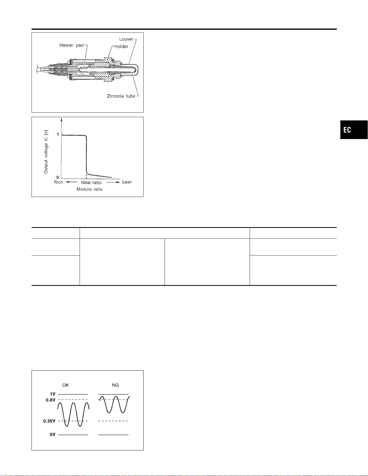
SEF463R
SEF288D
Component Description
NFEC1154
The heated oxygen sensor 1 is placed into the front tube. It detects
the amount of oxygen in the exhaust gas compared to the outside
air. The heated oxygen sensor 1 has a closed-end tube made of
ceramic zirconia. The zirconia generates voltage from approxi-
mately 1V in richer conditions to 0V in leaner conditions. The
heated oxygen sensor 1 signal is sent to the ECM. The ECM
adjusts the injection pulse duration to achieve the ideal air-fuel
ratio. The ideal air-fuel ratio occurs near the radical change from
1V to 0V.
CONSULT-II Reference Value in Data Monitor
Mode
NFEC1155
Specification data are reference values.
MONITOR ITEM CONDITION SPECIFICATION
HO2S1 (B1)
HO2S1 (B2)
I Engine: After warming up
Maintaining engine speed at 2,000
rpm
0 - 0.3V +, Approx. 0.6 - 1.0V
HO2S1 MNTR
(B1)
HO2S1 MNTR
(B2)
LEAN +, RICH
Changes more than 5 times during
10 seconds.
SEF299U
On Board Diagnosis Logic
NFEC1157
To judge the malfunction, the output from the heated oxygen sen-
sor 1 is monitored to determine whether the “rich” output is suffi-
ciently high. The “lean” output is sufficiently low. When both the
outputs are shifting to the rich side, the malfunction will be
detected.
GI
MA
EM
LC
FE
CL
MT
AT
AX
SU
BR
ST
RS
BT
HA
SC
EL
IDX
DTC P1144, P1164 HO2S1
Component Description
EC-499
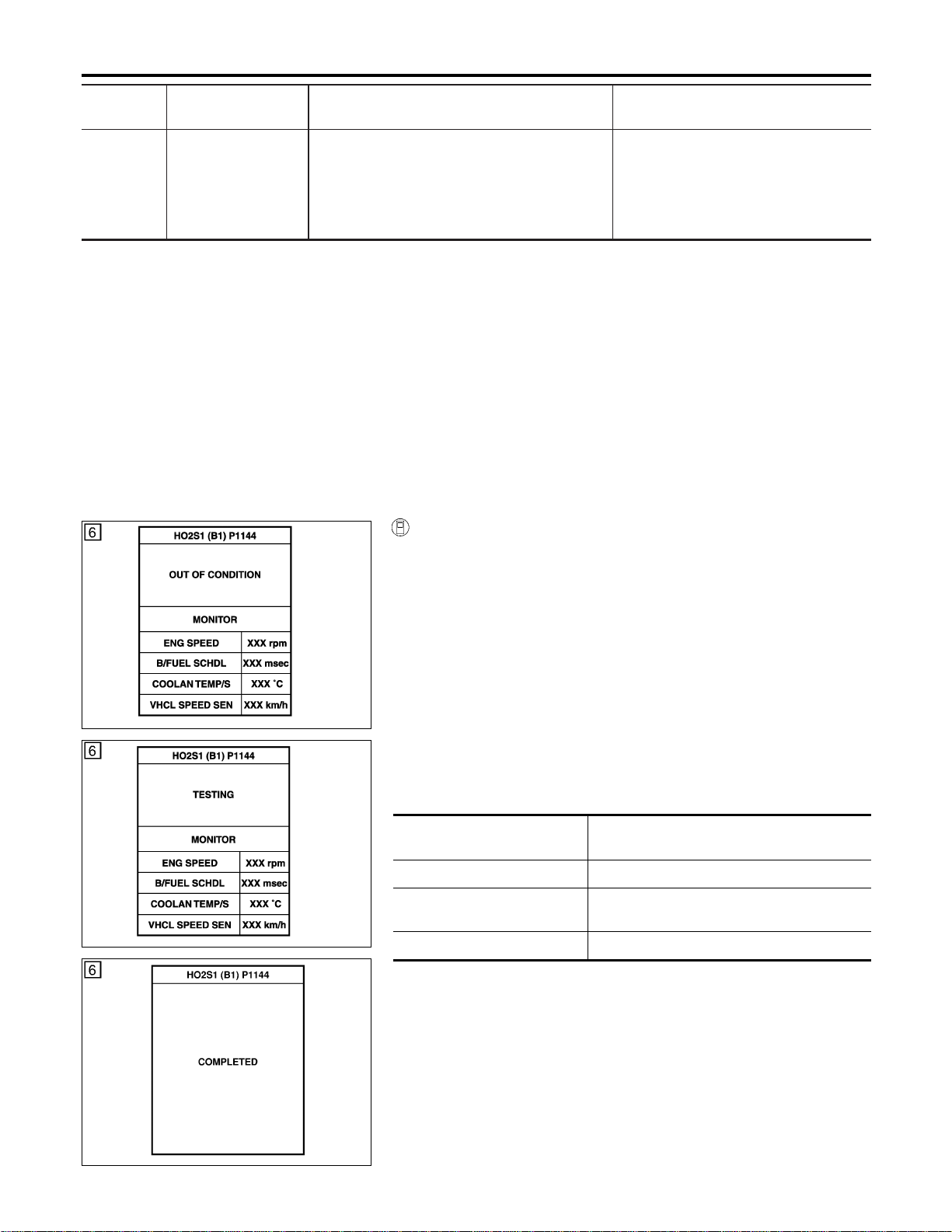
DTC No.
Trouble diagnosis
name
DTC Detecting Condition Possible Cause
P1144
1144
(Bank 1)
P1164
1164
(Bank 2)
Heated oxygen sen-
sor 1 rich shift moni-
toring
The maximum and minimum voltages from the
sensor are beyond the specified voltages.
I Heated oxygen sensor 1
I Fuel pressure
I Injectors
I Heated oxygen sensor 1 heater
DTC Confirmation Procedure
NFEC1158
CAUTION:
Always drive vehicle at a safe speed.
NOTE:
If “DTC Confirmation Procedure” has been previously conducted,
always turn ignition switch “OFF” and wait at least 10 seconds
before conducting the next test.
TESTING CONDITION:
I Always perform at a temperature above −10°C (14°F).
I Before performing the following procedure, confirm that
battery voltage is more than 11V at idle.
PBIB0548E
PBIB0549E
SEC772C
WITH CONSULT-II
NFEC1158S01
1) Start engine and warm it up to normal operating temperature.
2) Stop engine and wait at least 5 seconds.
3) Turn ignition switch “ON” and select “HO2S1 (B1)/(B2) P1144/
P1164” of “HO2S1” in “DTC WORK SUPPORT” mode with
CONSULT-II.
4) Touch “START”.
5) Start engine and let it idle for at least 3 minutes.
NOTE:
Never raise engine speed above 3,600 rpm after this step. If
the engine speed limit is exceeded, return to step 5.
6) When the following conditions are met, “TESTING” will be dis-
played on the CONSULT-II screen. Maintain the conditions
continuously until “TESTING” changes to “COMPLETED”. (It
will take approximately 50 seconds or more.)
ENG SPEED 1,200 - 2,600 rpm (A/T)
1,800 - 2,600 rpm (M/T)
Vehicle speed Less than 100 km/h (62 MPH)
B/FUEL SCHDL 3 - 9 msec (A/T)
2.5 - 9 msec (M/T)
Selector lever Suitable position
If “TESTING” is not displayed after 5 minutes, retry from
step 2.
7) Make sure that “OK” is displayed after touching “SELF-DIAG
RESULTS”. If “NG” is displayed, refer to “Diagnostic
Procedure”, EC-501.
DTC P1144, P1164 HO2S1
On Board Diagnosis Logic (Cont’d)
EC-500
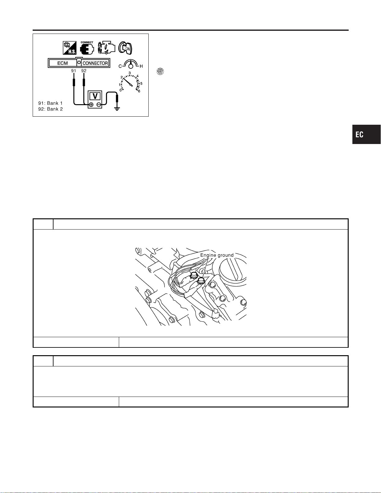
SEC902C
Overall Function Check
NFEC1159
Use this procedure to check the overall function of the heated oxy-
gen sensor 1 circuit. During this check, a DTC might not be con-
firmed.
WITH GST
NFEC1159S01
1) Start engine and warm it up to normal operating temperature.
2) Set voltmeter probes between ECM terminal 91 (HO2S1 bank
1 signal) or 92 (HO2S1 bank 2 signal) and engine ground.
3) Check one of the following with engine speed held at 2,000
rpm constant under no load.
I The maximum voltage is below 0.8V at least one time.
I The minimum voltage is below 0.35V at least one time.
4) If NG, go to “Diagnostic Procedure”, EC-501.
Diagnostic Procedure
NFEC1160
1 RETIGHTEN GROUND SCREWS
1. Turn ignition switch “OFF”.
2. Loosen and retighten engine ground screws.
SEC047D
© GO TO 2.
2 RETIGHTEN HEATED OXYGEN SENSOR 1
Loosen and retighten corresponding heated oxygen sensor 1.
Tightening torque:
40 - 60 N·m (4.1 - 6.1 kg-m, 30 - 44 ft-lb)
© GO TO 3.
GI
MA
EM
LC
FE
CL
MT
AT
AX
SU
BR
ST
RS
BT
HA
SC
EL
IDX
DTC P1144, P1164 HO2S1
Overall Function Check
EC-501
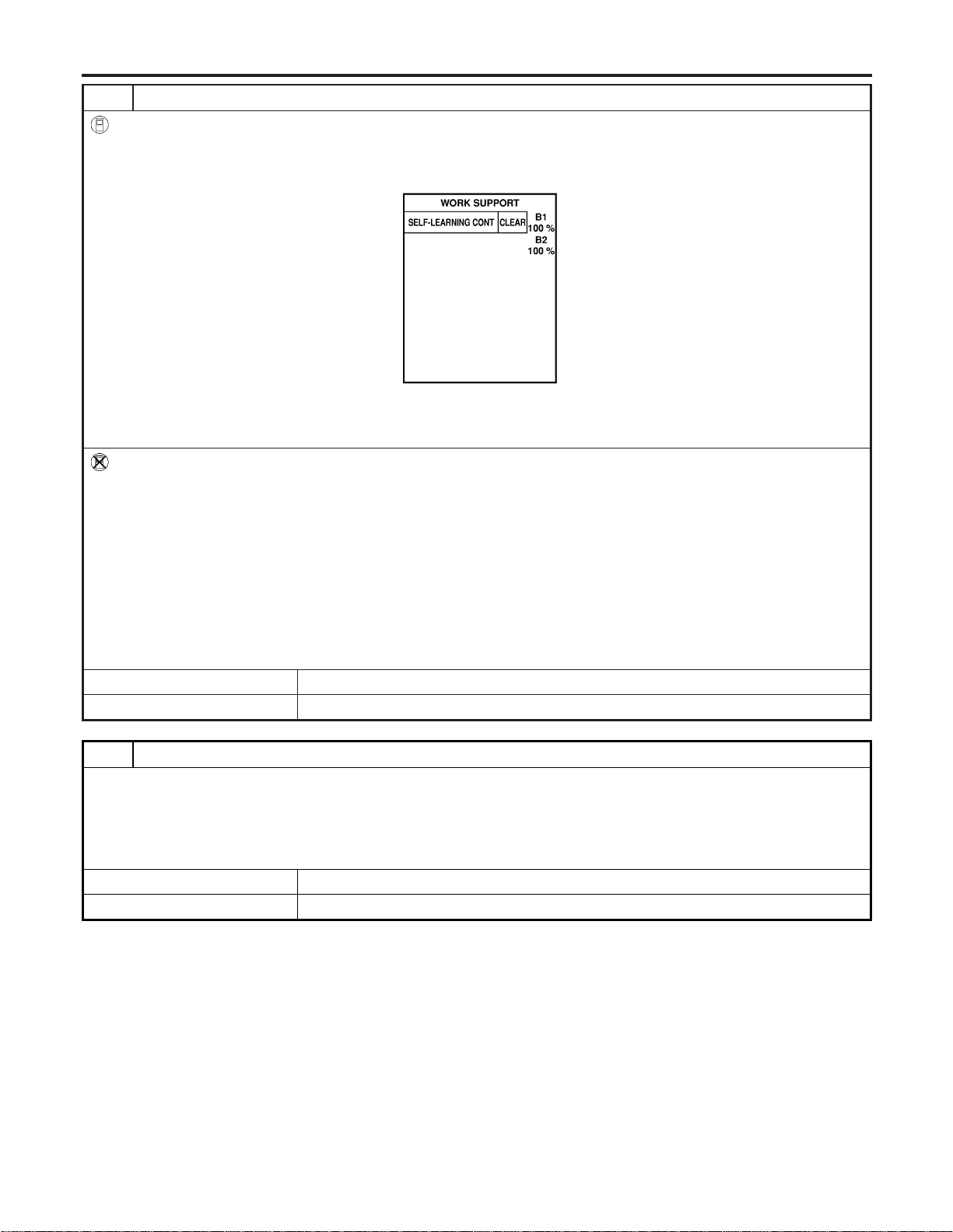
3 CLEAR THE SELF-LEARNING DATA
With CONSULT-II
1. Start engine and warm it up to normal operating temperature.
2. Select “SELF-LEARNING CONT” in “WORK SUPPORT” mode with CONSULT-II.
3. Clear the self-learning control coefficient by touching “CLEAR”.
SEF968Y
4. Run engine for at least 10 minutes at idle speed.
Is the 1st trip DTC P0172 or P0175 detected?
Is it difficult to start engine?
Without CONSULT-II
1. Start engine and warm it up to normal operating temperature.
2. Turn ignition switch “OFF”.
3. Disconnect mass air flow sensor harness connector, and restart and run engine for at least 5 seconds at idle speed.
4. Stop engine and reconnect mass air flow sensor harness connector.
5. Make sure DTC P0102 is displayed.
6. Erase the DTC memory. Refer to “HOW TO ERASE EMISSION-RELATED DIAGNOSTIC INFORMATION”, EC-91.
7. Make sure DTC P0000 is displayed.
8. Run engine for at least 10 minutes at idle speed.
Is the 1st trip DTC P0172 or P0175 detected?
Is it difficult to start engine?
YesorNo
Yes © Perform trouble diagnosis for DTC P0172, P0175. Refer to EC-275.
No © GO TO 4.
4 CHECK HO2S 1 CONNECTOR FOR WATER
1. Turn ignition switch “OFF”.
2. Disconnect heated oxygen sensor 1 harness connector.
3. Check connectors for water.
Water should not exist.
OK or NG
OK © GO TO 5.
NG © Repair or replace harness or connectors.
DTC P1144, P1164 HO2S1
Diagnostic Procedure (Cont’d)
EC-502
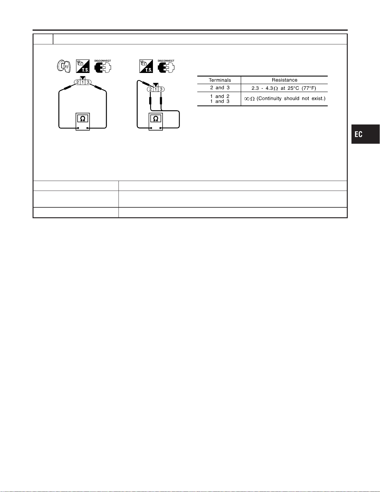
5 CHECK HEATED OXYGEN SENSOR 1 HEATER
Check resistance between HO2S1 terminals as follows.
SEF310X
CAUTION:
I Discard any heated oxygen sensor which has been dropped from a height of more than 0.5 m (19.7 in) onto a
hard surface such as a concrete floor; use a new one.
I Before installing new oxygen sensor, clean exhaust system threads using Oxygen Sensor Thread Cleaner tool
J-43897-18 or J-43897-12 and approved anti-seize lubricant.
OK or NG
OK (With CONSULT-II) © GO TO 6.
OK (Without CONSULT-
II)
© GO TO 7.
NG © Replace malfunctioning heated oxygen sensor 1.
GI
MA
EM
LC
FE
CL
MT
AT
AX
SU
BR
ST
RS
BT
HA
SC
EL
IDX
DTC P1144, P1164 HO2S1
Diagnostic Procedure (Cont’d)
EC-503
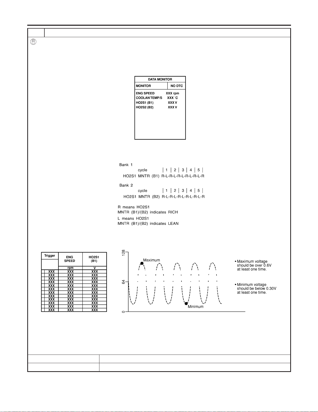
6 CHECK HEATED OXYGEN SENSOR 1
With CONSULT-II
1. Start engine and warm it up to normal operating temperature.
2. Select “MANU TRIG” and adjust “TRIGGER POINT” to 100% in “DATA MONITOR” mode with CONSULT-II.
3. Select “HO2S1 (B1)/(B2)” and “HO2S1 MNTR (B1)/(B2)”.
4. Hold engine speed at 2,000 rpm under no load during the following steps.
5. Touch “RECORD” on CONSULT-II screen.
SEF967Y
6. Check the following.
I “HO2S1 MNTR (B1)/(B2)” in “DATA MONITOR” mode changes from “RICH” to “LEAN” to “RICH” 5 times in 10 seconds.
5 times (cycles) are counted as shown below.
SEF647Y
I “HO2S1 (B1)/(B2)” voltage goes above 0.6V at least once.
I “HO2S1 (B1)/(B2)” voltage goes below 0.3V at least once.
I “HO2S1 (B1)/(B2)” voltage never exceeds 1.0V.
SEF648Y
CAUTION:
I Discard any heated oxygen sensor which has been dropped from a height of more than 0.5 m (19.7 in) onto a
hard surface such as a concrete floor; use a new one.
I Before installing new oxygen sensor, clean exhaust system threads using Oxygen Sensor Thread Cleaner tool
J-43897-18 or J-43897-12 and approved anti-seize lubricant.
OK or NG
OK © GO TO 8.
NG © Replace malfunctioning heated oxygen sensor 1.
DTC P1144, P1164 HO2S1
Diagnostic Procedure (Cont’d)
EC-504
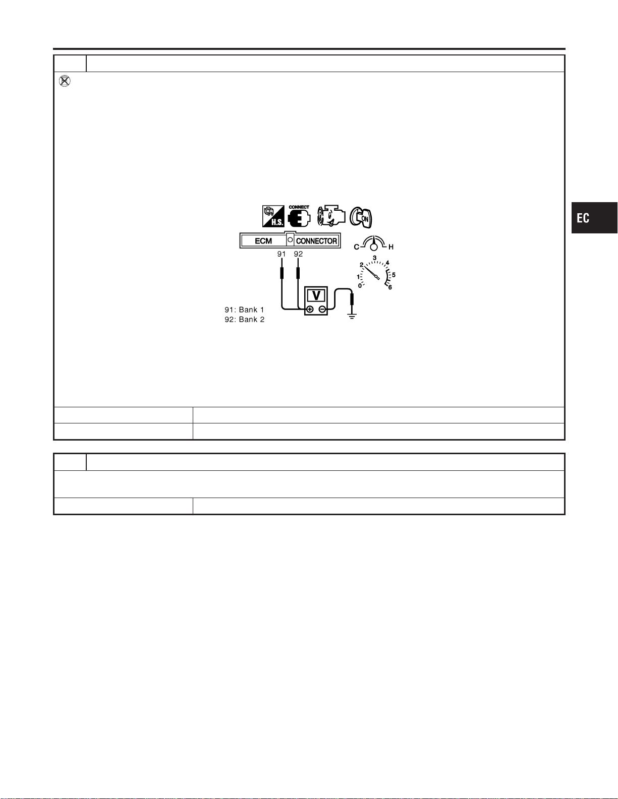
7 CHECK HEATED OXYGEN SENSOR 1
Without CONSULT-II
1. Start engine and warm it up to normal operating temperature.
2. Set voltmeter probes between ECM terminal 91 (HO2S1 bank 1 signal) or 92 (HO2S1 bank 2 signal) and engine
ground.
3. Check the following with engine speed held at 2,000 rpm constant under no load.
I The voltage fluctuates between 0 to 0.3V and 0.6 to 1.0V more than 5 times within 10 seconds.
I The maximum voltage is over 0.6V at least one time.
I The minimum voltage is below 0.3V at least one time.
I The voltage never exceeds 1.0V.
1 time: 0 - 0.3V , 0.6 - 1.0V , 0 - 0.3V
2 times: 0 - 0.3V , 0.6 - 1.0V , 0 - 0.3V , 0.6 - 1.0V , 0 - 0.3V
SEC085D
CAUTION:
I Discard any heated oxygen sensor which has been dropped from a height of more than 0.5 m (19.7 in) onto a
hard surface such as a concrete floor; use a new one.
I Before installing new oxygen sensor, clean exhaust system threads using Oxygen Sensor Thread Cleaner tool
J-43897-18 or J-43897-12 and approved anti-seize lubricant.
OK or NG
OK © GO TO 8.
NG © Replace malfunctioning heated oxygen sensor 1.
8 CHECK INTERMITTENT INCIDENT
Refer to “TROUBLE DIAGNOSIS FOR INTERMITTENT INCIDENT”, EC-156.
For circuit, refer to “Wiring Diagram”, EC-231.
© INSPECTION END
GI
MA
EM
LC
FE
CL
MT
AT
AX
SU
BR
ST
RS
BT
HA
SC
EL
IDX
DTC P1144, P1164 HO2S1
Diagnostic Procedure (Cont’d)
EC-505
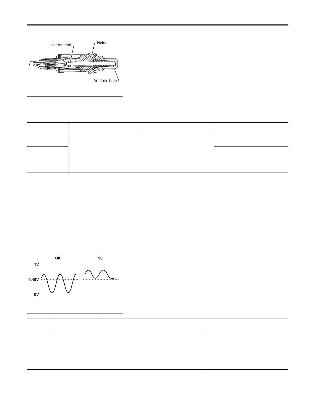
SEF327R
Component Description
NFEC1161
The heated oxygen sensor 2, after three way catalyst, monitors the
oxygen level in the exhaust gas on each bank.
Even if switching characteristics of the heated oxygen sensor 1 are
shifted, the air fuel ratio is controlled to stoichiometric, by the sig-
nal from the heated oxygen sensor 2.
This sensor is made of ceramic zirconia. The zirconia generates
voltage from approximately 1V in richer conditions to 0V in leaner
conditions.
Under normal conditions the heated oxygen sensor 2 is not used
for engine control operation.
CONSULT-II Reference Value in Data Monitor
Mode
NFEC1162
Specification data are reference values.
MONITOR ITEM CONDITION SPECIFICATION
HO2S2 (B1)
HO2S2 (B2)
I Engine: After warming up
Revving engine from idle up to
2,000 rpm
0 - 0.3V +, Approx. 0.6 - 1.0V
HO2S2 MNTR
(B1)
HO2S2 MNTR
(B2)
LEAN +, RICH
SEF972Z
On Board Diagnosis Logic
NFEC1164
The heated oxygen sensor 2 has a much longer switching time
between rich and lean than the heated oxygen sensor 1. The oxy-
gen storage capacity before the three way catalyst causes the
longer switching time. To judge the malfunctions of heated oxygen
sensor 2, ECM monitors whether the minimum voltage of sensor
is sufficiently low during the various driving condition such as fuel-
cut.
DTC No.
Trouble diagnosis
name
DTC Detecting Condition Possible Cause
P1146
1146
(Bank 1)
P1166
1166
(Bank 2)
Heated oxygen sen-
sor 2 minimum volt-
age monitoring
The minimum voltage from the sensor is not
reached to the specified voltage.
I Harness or connectors
(The sensor circuit is open or
shorted.)
I Heated oxygen sensor 2
I Fuel pressure
I Injectors
DTC P1146, P1166 HO2S2
Component Description
EC-506
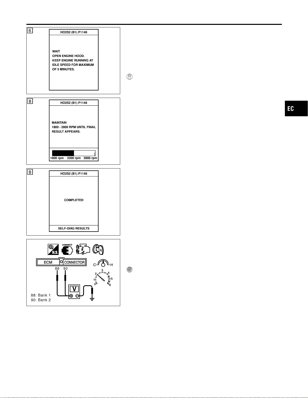
SEC773C
DTC Confirmation Procedure
NFEC1165
SEC774C
SEC775C
NOTE:
If “DTC Confirmation Procedure” has been previously conducted,
always turn ignition switch “OFF” and wait at least 10 seconds
before conducting the next test.
TESTING CONDITION:
Open engine hood before conducting following procedure.
WITH CONSULT-II
NFEC1165S01
1) Start engine and warm it up to normal operating temperature.
2) Turn ignition switch “OFF” and wait at least 10 seconds.
3) Turn ignition switch “ON”.
4) Select “DATA MONITOR” mode with CONSULT-II.
5) Make sure that “COOLAN TEMP/S” indicates more than 70°C
(158°F).
6) Select “HO2S2 (B1)/(B2) P1146/P1166” of “HO2S2” in “DTC
WORK SUPPORT” mode with CONSULT-II.
7) Start engine and follow the instruction of CONSULT-II.
8) Make sure that “OK” is displayed after touching “SELF-DIAG
RESULTS”.
If NG is displayed, refer to “Diagnostic Procedure”, EC-511.
If “CANNOT BE DIAGNOSED” is displayed, perform the fol-
lowing.
a) Stop engine and cool down until “COOLAN TEMP/S” indicates
less than 70°C (158°F).
b) Turn ignition switch “ON”.
c) Select “DATA MONITOR” mode with CONSULT-II.
d) Start engine.
e) Return to step 6 again when the “COOLAN TEMP/S” reaches
to 70°C (158°F).
SEC903C
Overall Function Check
NFEC1166
Use this procedure to check the overall function of the heated oxy-
gen sensor 2 circuit. During this check, a DTC might not be con-
firmed.
WITH GST
NFEC1166S01
1) Start engine and drive vehicle at a speed of more than 70 km/h
(43 MPH) for 2 consecutive minutes.
2) Stop vehicle with engine running.
3) Set voltmeter probes between ECM terminal 88 (HO2S2 bank
1 signal) or 90 (HO2S2 bank 2 signal) and engine ground.
4) Check the voltage when racing up to 4,000 rpm under no load
at least 10 times.
(Depress and release accelerator pedal as soon as possible.)
The voltage should be below 0.48V at least once during
this procedure.
If the voltage can be confirmed in step 4, step 5 is not
necessary.
5) Keep vehicle at idling for 10 minutes, then check the voltage.
Or check the voltage when coasting from 80 km/h (50 MPH)
in 3rd gear position (M/T), “D” position with “OD” OFF (A/T).
The voltage should be below 0.48V at least once during
this procedure.
GI
MA
EM
LC
FE
CL
MT
AT
AX
SU
BR
ST
RS
BT
HA
SC
EL
IDX
DTC P1146, P1166 HO2S2
DTC Confirmation Procedure
EC-507

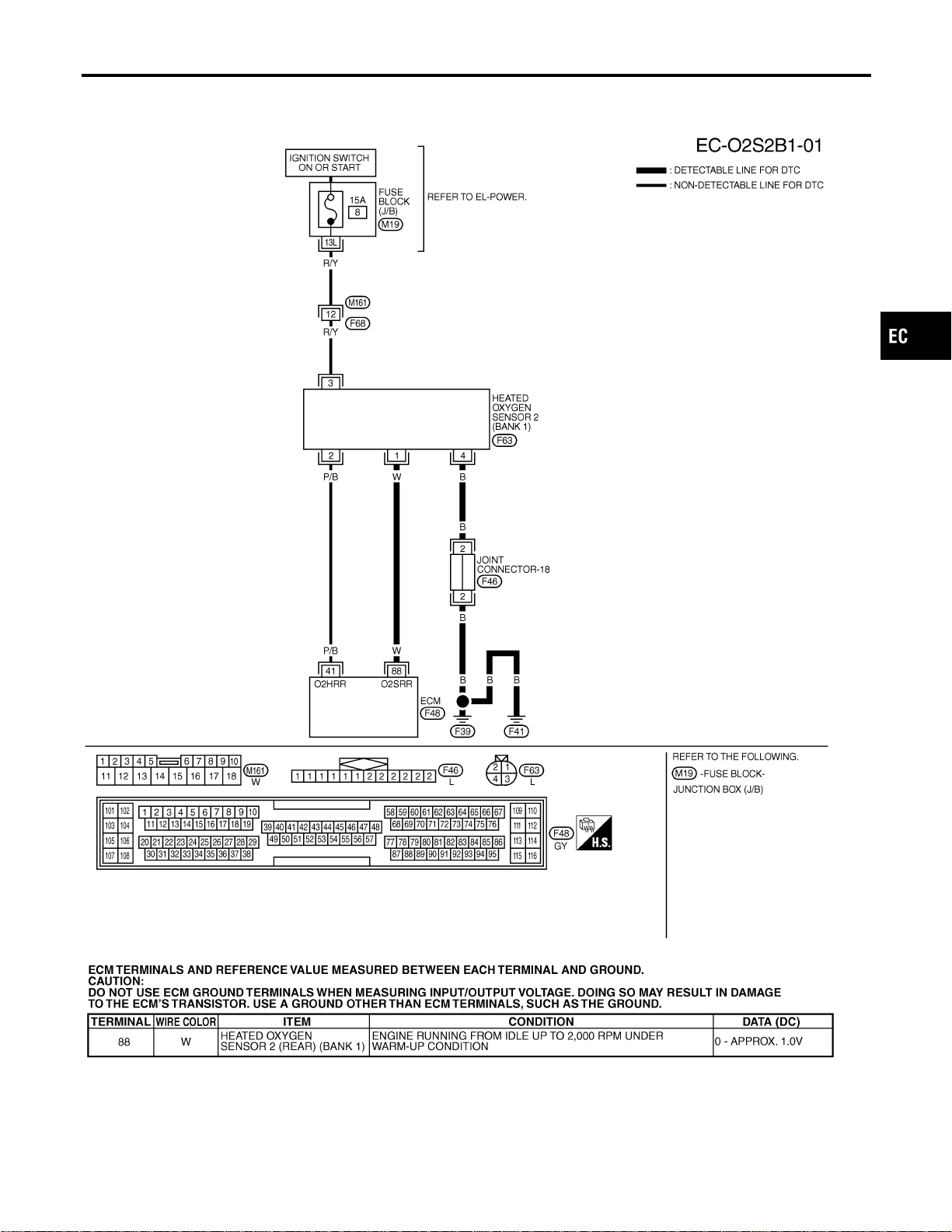
Wiring Diagram
=NFEC1167
BANK 1
NFEC1167S01
MEC483D
SEF657XF
GI
MA
EM
LC
FE
CL
MT
AT
AX
SU
BR
ST
RS
BT
HA
SC
EL
IDX
DTC P1146, P1166 HO2S2
Wiring Diagram
EC-509
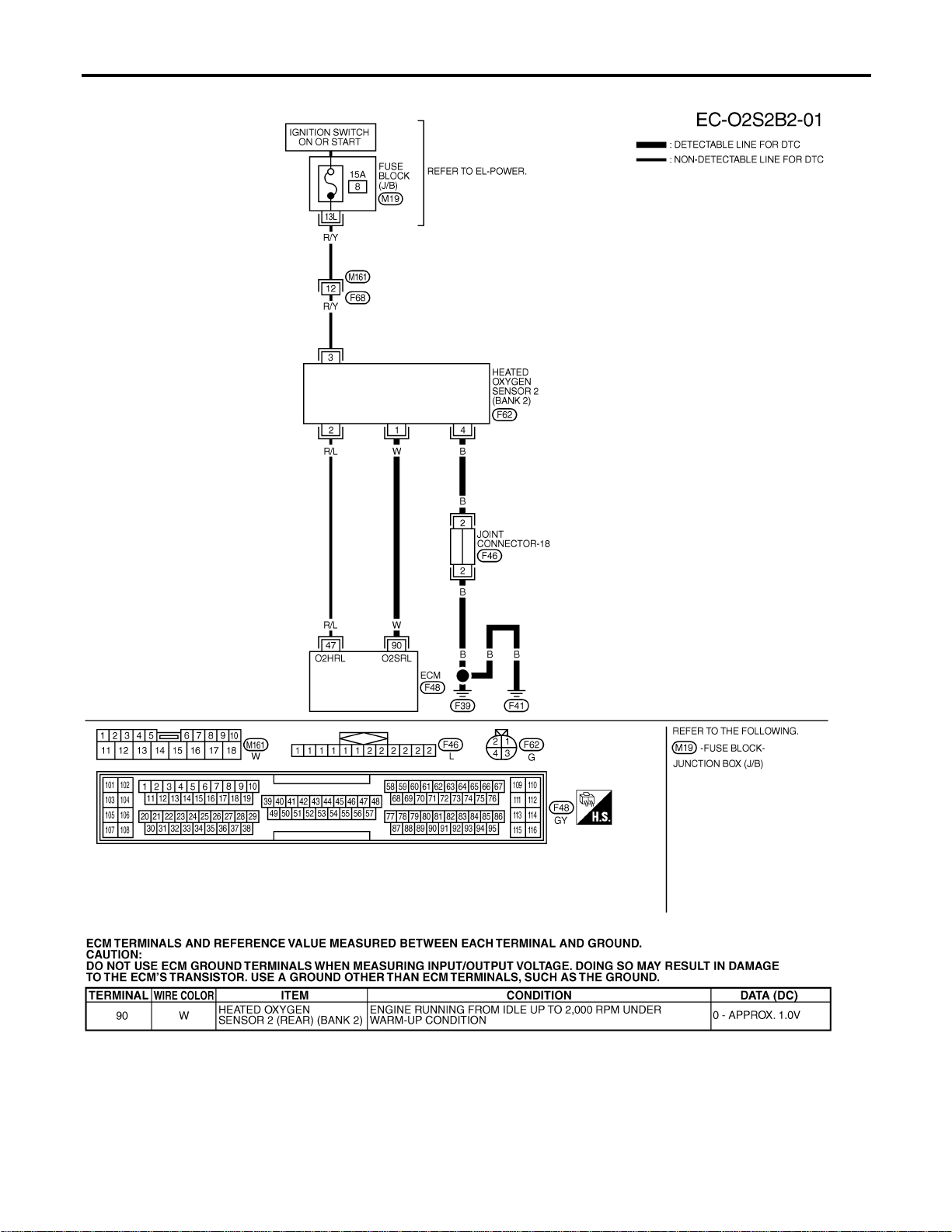
BANK 2
NFEC1167S02
MEC484D
SEF658XF
DTC P1146, P1166 HO2S2
Wiring Diagram (Cont’d)
EC-510
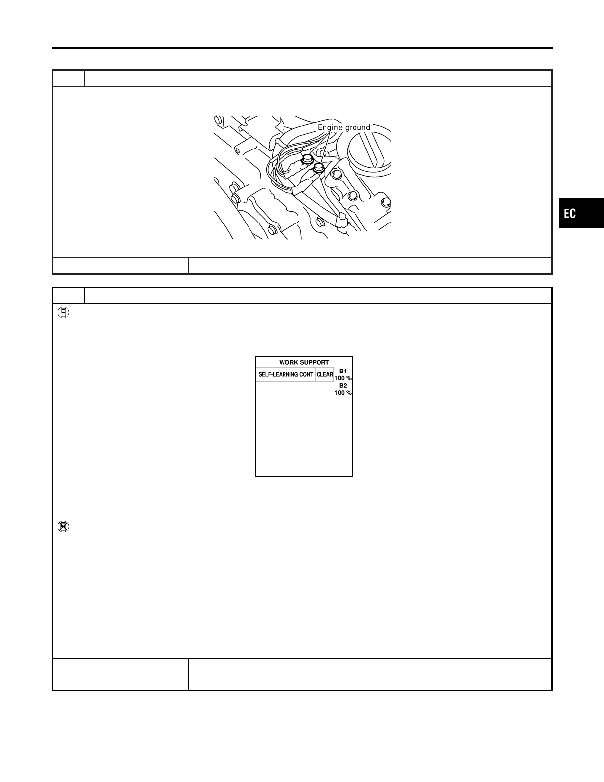
Diagnostic Procedure
NFEC1168
1 RETIGHTEN GROUND SCREWS
1. Turn ignition switch “OFF”.
2. Loosen and retighten engine ground screws.
SEC047D
© GO TO 2.
2 CLEAR THE SELF-LEARNING DATA
With CONSULT-II
1. Start engine and warm it up to normal operating temperature.
2. Select “SELF-LEARNING CONT” in “WORK SUPPORT” mode with CONSULT-II.
3. Clear the self-learning control coefficient by touching “CLEAR”.
SEF968Y
4. Run engine for at least 10 minutes at idle speed.
Is the 1st trip DTC P0172 or P0175 detected?
Is it difficult to start engine?
Without CONSULT-II
1. Start engine and warm it up to normal operating temperature.
2. Turn ignition switch “OFF”.
3. Disconnect mass air flow sensor harness connector, and restart and run engine for at least 5 seconds at idle speed.
4. Stop engine and reconnect mass air flow sensor harness connector.
5. Make sure DTC P0102 is displayed.
6. Erase the DTC memory. Refer to “HOW TO ERASE EMISSION-RELATED DIAGNOSTIC INFORMATION”, EC-91.
7. Make sure DTC P0000 is displayed.
8. Run engine for at least 10 minutes at idle speed.
Is the 1st trip DTC P0172 or P0175 detected?
Is it difficult to start engine?
YesorNo
Yes © Perform trouble diagnosis for DTC P0172, P0175. Refer to EC-275.
No © GO TO 3.
GI
MA
EM
LC
FE
CL
MT
AT
AX
SU
BR
ST
RS
BT
HA
SC
EL
IDX
DTC P1146, P1166 HO2S2
Diagnostic Procedure
EC-511
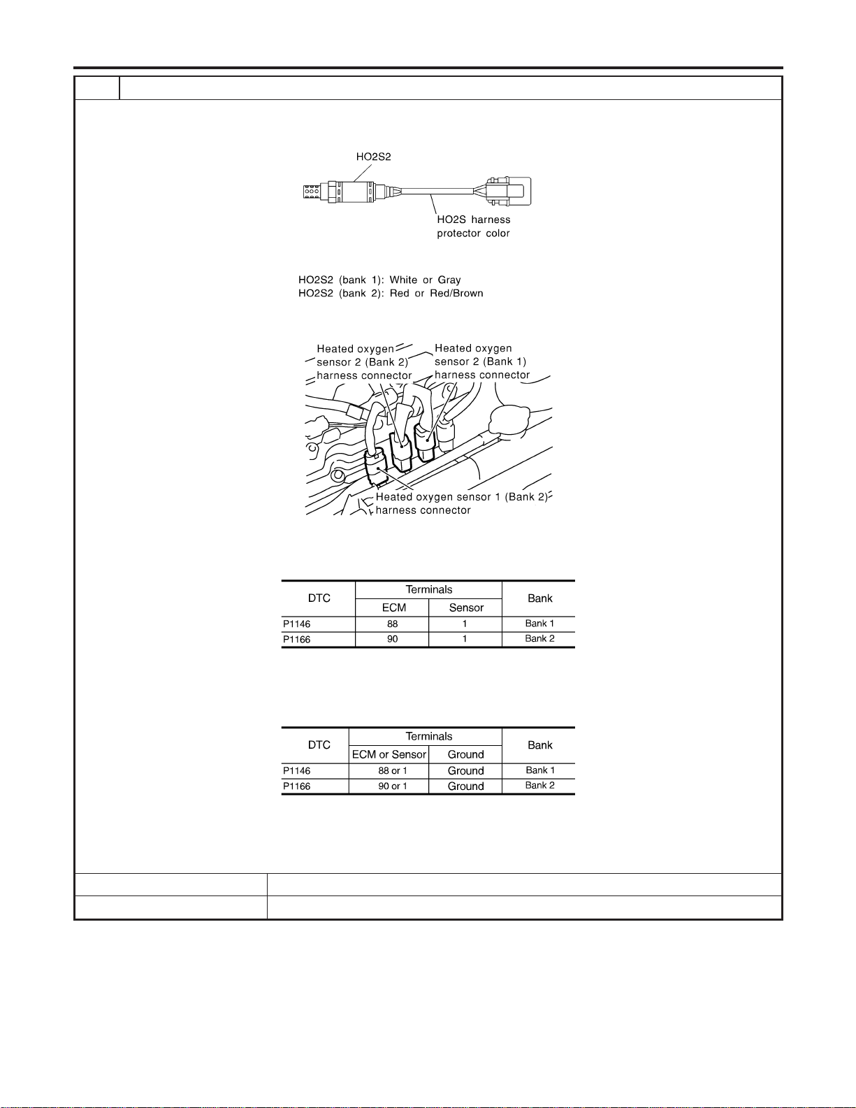
3 CHECK HO2S2 INPUT SIGNAL CIRCUIT FOR OPEN AND SHORT
1. Turn ignition switch “OFF”.
2. Check heated oxygen sensor 2 harness protector color.
SEF372ZB
3. Disconnect corresponding heated oxygen sensor 2 harness connector.
SEC134D
4. Disconnect ECM harness connector.
5. Check harness continuity between ECM terminal and HO2S2 terminal as follows.
Refer to Wiring Diagram.
MTBL1161
Continuity should exist.
6. Check harness continuity between ECM terminal or HO2S2 terminal and ground as follows.
Refer to Wiring Diagram.
MTBL1162
Continuity should not exist.
7. Also check harness for short to power.
OK or NG
OK © GO TO 4.
NG © Repair open circuit or short to ground or short to power in harness or connectors.
DTC P1146, P1166 HO2S2
Diagnostic Procedure (Cont’d)
EC-512
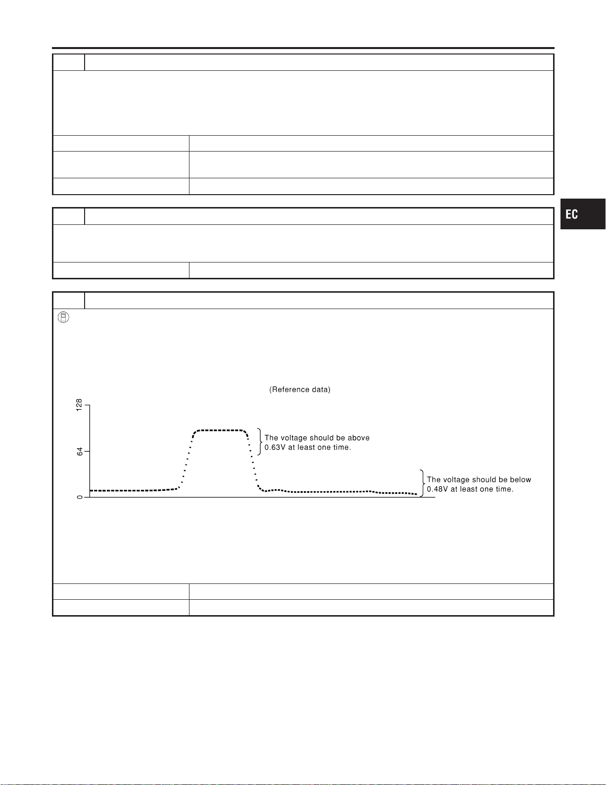
4 CHECK HO2S2 GROUND CIRCUIT FOR OPEN AND SHORT
1. Check harness continuity between HO2S2 terminal 4 and engine ground.
Refer to Wiring Diagram.
Continuity should exist.
2. Also check harness for short to power.
OK or NG
OK (With CONSULT-II) © GO TO 6.
OK (Without CONSULT-
II)
© GO TO 7.
NG © GO TO 5.
5 DETECT MALFUNCTIONING PART
Check the following.
I Joint connectors-18
I Harness for open or short between heated oxygen sensor 2 and ground
© Repair open circuit or short to power in harness or connectors.
6 CHECK HEATED OXYGEN SENSOR 2
With CONSULT-II
1. Start engine and drive vehicle at a speed of more than 70 km/h (43 MPH) for 2 consecutive minutes.
2. Stop vehicle with engine running.
3. Select “FUEL INJECTION” in “ACTIVE TEST” mode, and select “HO2S2 (B1)/(B2)” as the monitor item with CONSULT-
II.
4. Check “HO2S2 (B1)/(B2)” at idle speed when adjusting “FUEL INJECTION” to ±25%.
SEF066YA
“HO2S2 (B1)/(B2)” should be above 0.63V at least once when the “FUEL INJECTION” is +25%.
“HO2S2 (B1)/(B2)” should be below 0.48V at least once when the “FUEL INJECTION” is −25%.
CAUTION:
Discard any heated oxygen sensor which has been dropped from a height of more than 0.5 m (19.7 in) onto a
hard surface such as a concrete floor; use a new one.
OK or NG
OK © GO TO 10.
NG © GO TO 9.
GI
MA
EM
LC
FE
CL
MT
AT
AX
SU
BR
ST
RS
BT
HA
SC
EL
IDX
DTC P1146, P1166 HO2S2
Diagnostic Procedure (Cont’d)
EC-513
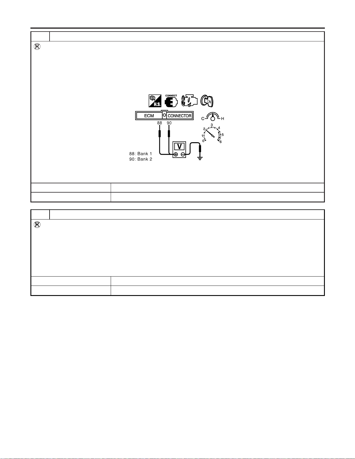
7 CHECK HEATED OXYGEN SENSOR 2-I
Without CONSULT-II
1. Start engine and drive vehicle at a speed of more than 70 km/h (43 MPH) for 2 consecutive minutes.
2. Stop vehicle with engine running.
3. Set voltmeter probes between ECM terminal 88 (HO2S2 bank 1 signal) or 90 (HO2S2 bank 2 signal) and engine
ground.
4. Check the voltage when rewing up to 4,000 rpm under no load at least 10 times.
(Depress and release accelerator pedal as soon as possible.)
SEC903C
The voltage should be above 0.63V at least once during this procedure.
OK or NG
OK © GO TO 10.
NG © GO TO 8.
8 CHECK HEATED OXYGEN SENSOR 2-II
Without CONSULT-II
Idle vehicle for 10 minutes, then check voltage between the same terminals as in Test No. 7; or check voltage when coast-
ing from 80 km/h (50 MPH) in 3rd gear position (M/T), “D” position with “OD” OFF (A/T).
The voltage should go below 0.48V at least once during this procedure.
CAUTION:
Discard any heated oxygen sensor which has been dropped from a height of more than 0.5 m (19.7 in) onto a
hard surface such as a concrete floor; use a new one.
OK or NG
OK © GO TO 10.
NG © GO TO 9.
DTC P1146, P1166 HO2S2
Diagnostic Procedure (Cont’d)
EC-514
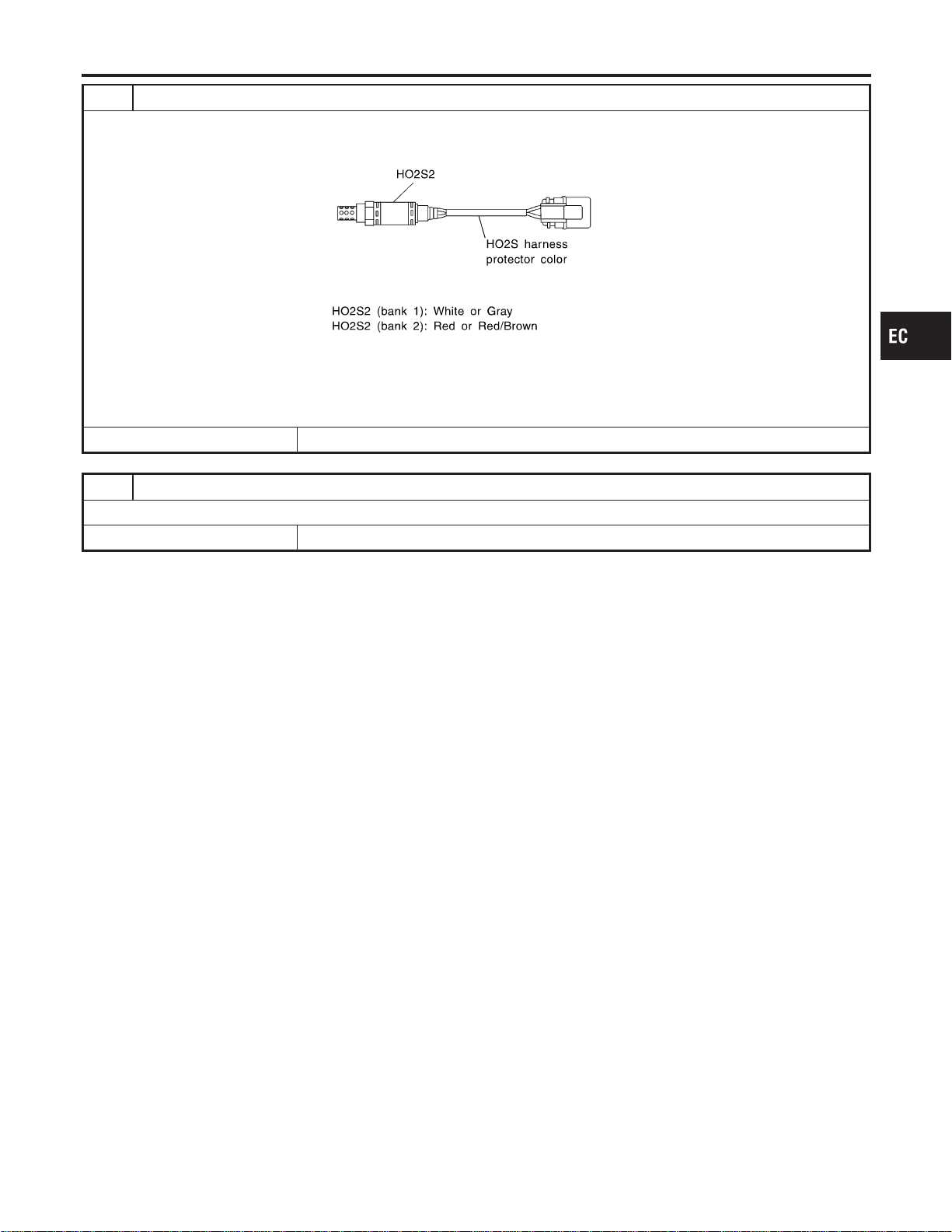
9 REPLACE HEATED OXYGEN SENSOR 2
1. Stop vehicle and turn ignition switch OFF.
2. Check heated oxygen sensor 2 harness protector color.
SEF372ZB
CAUTION:
Before installing new oxygen sensor, clean exhaust system threads using Oxygen Sensor Thread Cleaner tool
J-43897-18 or J-43897-12 and approved anti-seize lubricant.
© Replace malfunctioning heated oxygen sensor 2.
10 CHECK INTERMITTENT INCIDENT
Refer to “TROUBLE DIAGNOSIS FOR INTERMITTENT INCIDENT”, EC-156.
© INSPECTION END
GI
MA
EM
LC
FE
CL
MT
AT
AX
SU
BR
ST
RS
BT
HA
SC
EL
IDX
DTC P1146, P1166 HO2S2
Diagnostic Procedure (Cont’d)
EC-515
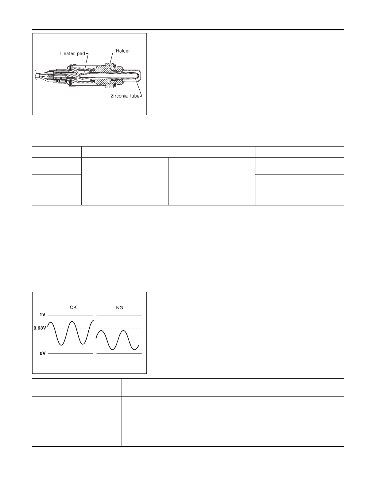
SEF327R
Component Description
NFEC1169
The heated oxygen sensor 2, after three way catalyst, monitors the
oxygen level in the exhaust gas on each bank.
Even if switching characteristics of the heated oxygen sensor 1 are
shifted, the air fuel ratio is controlled to stoichiometric, by the sig-
nal from the heated oxygen sensor 2.
This sensor is made of ceramic zirconia. The zirconia generates
voltage from approximately 1V in richer conditions to 0V in leaner
conditions.
Under normal conditions the heated oxygen sensor 2 is not used
for engine control operation.
CONSULT-II Reference Value in Data Monitor
Mode
NFEC1170
Specification data are reference values.
MONITOR ITEM CONDITION SPECIFICATION
HO2S2 (B1)
HO2S2 (B2)
I Engine: After warming up
Revving engine from idle up to
2,000 rpm
0 - 0.3V +, Approx. 0.6 - 1.0V
HO2S2 MNTR
(B1)
HO2S2 MNTR
(B2)
LEAN +, RICH
SEF303UD
On Board Diagnosis Logic
NFEC1172
The heated oxygen sensor 2 has a much longer switching time
between rich and lean than the heated oxygen sensor 1. The oxy-
gen storage capacity before the three way catalyst causes the
longer switching time. To judge the malfunctions of heated oxygen
sensor 2, ECM monitors whether the maximum voltage of the sen-
sor is sufficiently high during the various driving condition such as
fuel-cut.
DTC No.
Trouble diagnosis
name
DTC Detecting Condition Possible Cause
P1147
1147
(Bank 1)
P1167
1167
(Bank 2)
Heated oxygen sen-
sor 2 maximum volt-
age monitoring
The maximum voltage from the sensor is not
reached to the specified voltage.
I Harness or connectors
(The sensor circuit is open or
shorted.)
I Heated oxygen sensor 2
I Fuel pressure
I Injectors
I Intake air leaks
DTC P1147, P1167 HO2S2
Component Description
EC-516
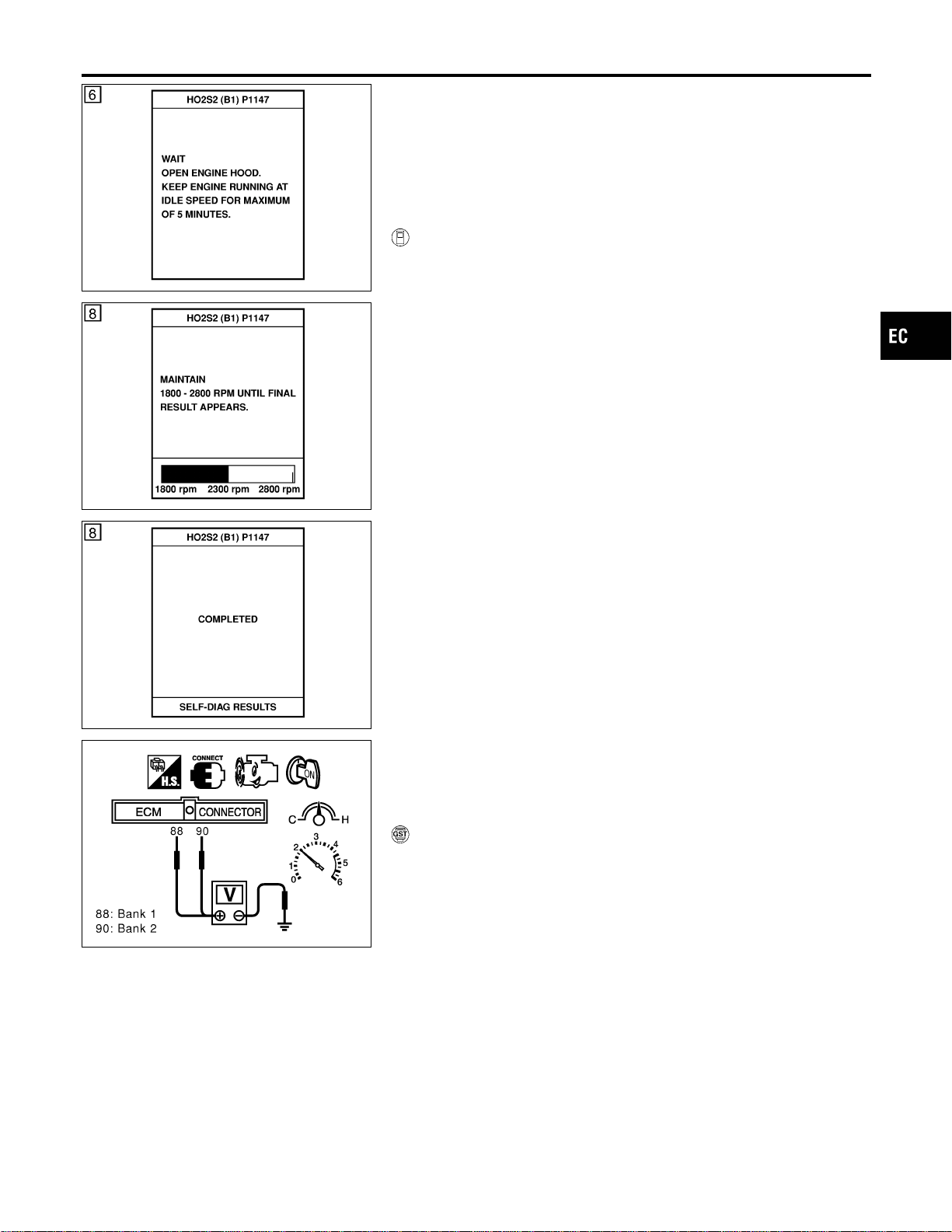
SEC776C
DTC Confirmation Procedure
NFEC1173
SEC777C
SEC778C
NOTE:
If “DTC Confirmation Procedure” has been previously conducted,
always turn ignition switch “OFF” and wait at least 10 seconds
before conducting the next test.
TESTING CONDITION:
Open engine hood before conducting following procedure.
WITH CONSULT-II
NFEC1173S01
1) Start engine and warm it up to normal operating temperature.
2) Turn ignition switch “OFF” and wait at least 10 seconds.
3) Turn ignition switch “ON”.
4) Select “DATA MONITOR” mode with CONSULT-II.
5) Make sure that “COOLAN TEMP/S” indicates more than 70°C
(158°F).
6) Select “HO2S2 (B1)/(B2) P1147/P1167” of “HO2S2” in “DTC
WORK SUPPORT” mode with CONSULT-II.
7) Start engine and follow the instruction of CONSULT-II.
8) Make sure that “OK” is displayed after touching “SELF-DIAG
RESULTS”.
If NG is displayed, refer to “Diagnostic Procedure”, EC-521.
If “CANNOT BE DIAGNOSED” is displayed, perform the fol-
lowing.
a) Stop engine and cool down until “COOLAN TEMP/S” indicates
less than 70°C (158°F).
b) Turn ignition switch “ON”.
c) Select “DATA MONITOR” mode with CONSULT-II.
d) Start engine.
e) Return to step 6 again when the “COOLAN TEMP/S” reaches
to 70°C (158°F).
SEC903C
Overall Function Check
NFEC1174
Use this procedure to check the overall function of the heated oxy-
gen sensor 2 circuit. During this check, a DTC might not be con-
firmed.
WITH GST
NFEC1174S01
1) Start engine and drive vehicle at a speed of more than 70 km/h
(43 MPH) for 2 consecutive minutes.
2) Stop vehicle with engine running.
3) Set voltmeter probes between ECM terminal 88 (HO2S2 bank
1 signal) or 90 (HO2S2 bank 2 signal) and engine ground.
4) Check the voltage when racing up to 4,000 rpm under no load
at least 10 times.
(Depress and release accelerator pedal as soon as possible.)
The voltage should be above 0.63V at least once during
this procedure.
If the voltage can be confirmed in step 4, step 5 is not
necessary.
5) Keep vehicle at idling for 10 minutes, then check the voltage.
Or check the voltage when coasting from 80 km/h (50 MPH)
in 3rd gear position (M/T), “D” position with “OD” OFF (A/T).
The voltage should be above 0.63V at least once during
this procedure.
GI
MA
EM
LC
FE
CL
MT
AT
AX
SU
BR
ST
RS
BT
HA
SC
EL
IDX
DTC P1147, P1167 HO2S2
DTC Confirmation Procedure
EC-517

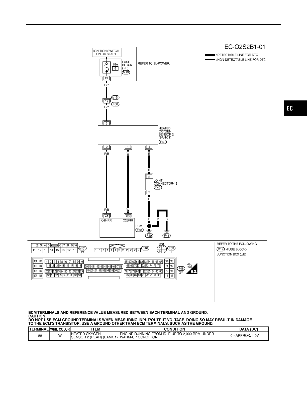
Wiring Diagram
=NFEC1175
BANK 1
NFEC1175S01
MEC483D
SEF657XF
GI
MA
EM
LC
FE
CL
MT
AT
AX
SU
BR
ST
RS
BT
HA
SC
EL
IDX
DTC P1147, P1167 HO2S2
Wiring Diagram
EC-519
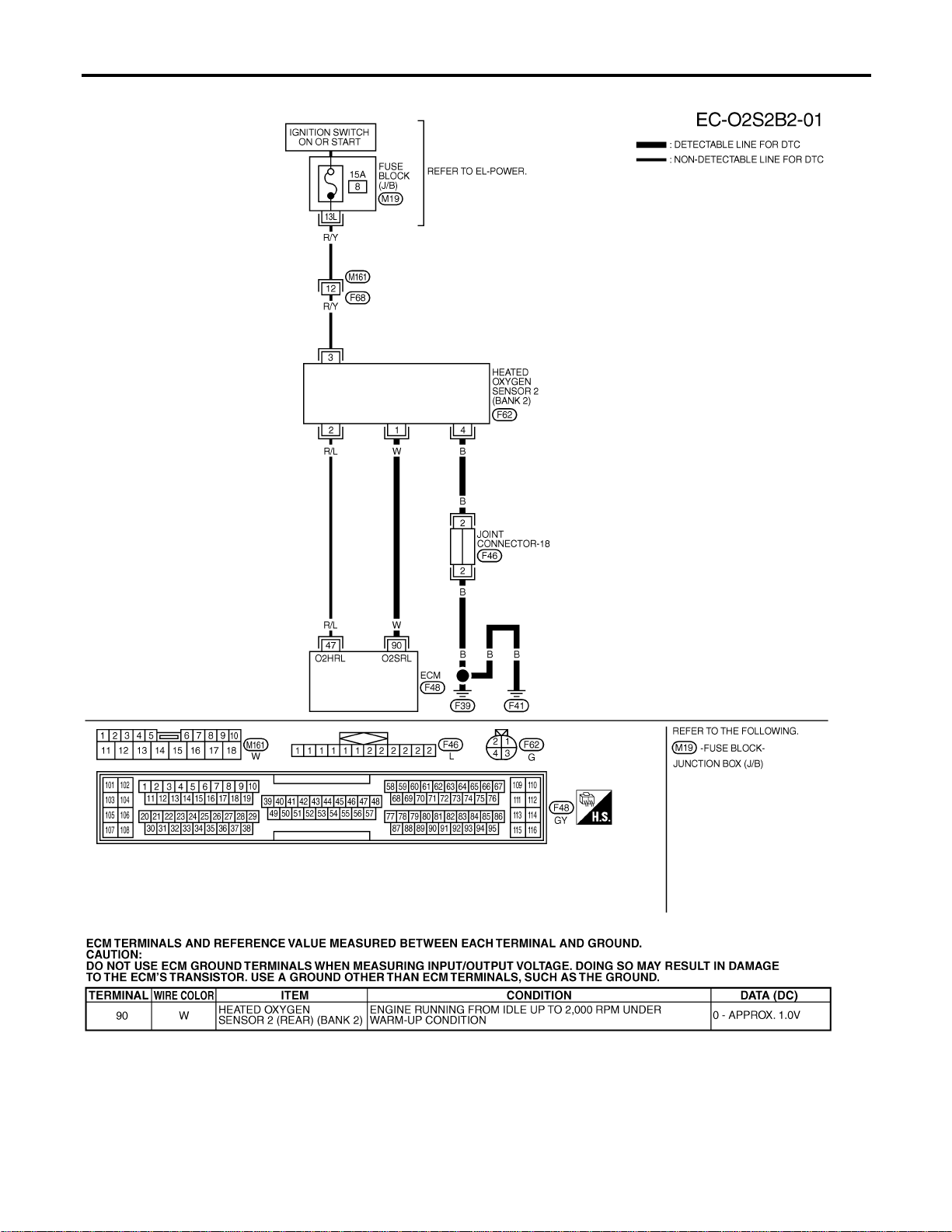
BANK 2
NFEC1175S02
MEC484D
SEF658XF
DTC P1147, P1167 HO2S2
Wiring Diagram (Cont’d)
EC-520
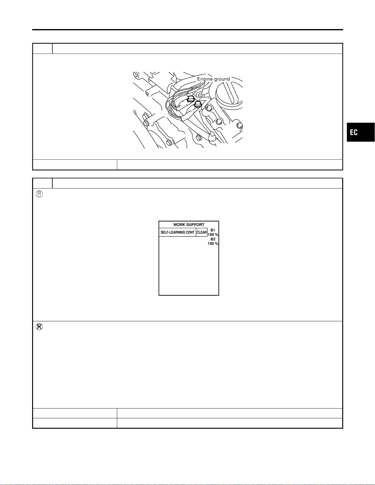
Diagnostic Procedure
NFEC1176
1 RETIGHTEN GROUND SCREWS
1. Turn ignition switch “OFF”.
2. Loosen and retighten engine ground screws.
SEC047D
© GO TO 2.
2 CLEAR THE SELF-LEARNING DATA
With CONSULT-II
1. Start engine and warm it up to normal operating temperature.
2. Select “SELF-LEARNING CONT” in “WORK SUPPORT” mode with CONSULT-II.
3. Clear the self-learning control coefficient by touching “CLEAR”.
SEF968Y
4. Run engine for at least 10 minutes at idle speed.
Is the 1st trip DTC P0171 or P0174 detected?
Is it difficult to start engine?
Without CONSULT-II
1. Start engine and warm it up to normal operating temperature.
2. Turn ignition switch “OFF”.
3. Disconnect mass air flow sensor harness connector, and restart and run engine for at least 5 seconds at idle speed.
4. Stop engine and reconnect mass air flow sensor harness connector.
5. Make sure DTC P0102 is displayed.
6. Erase the DTC memory. Refer to “HOW TO ERASE EMISSION-RELATED DIAGNOSTIC INFORMATION”, EC-91.
7. Make sure DTC P0000 is displayed.
8. Run engine for at least 10 minutes at idle speed.
Is the 1st trip DTC P0171 or P0174 detected?
Is it difficult to start engine?
YesorNo
Yes © Perform trouble diagnosis for DTC P0171, P0174. Refer to EC-267.
No © GO TO 3.
GI
MA
EM
LC
FE
CL
MT
AT
AX
SU
BR
ST
RS
BT
HA
SC
EL
IDX
DTC P1147, P1167 HO2S2
Diagnostic Procedure
EC-521
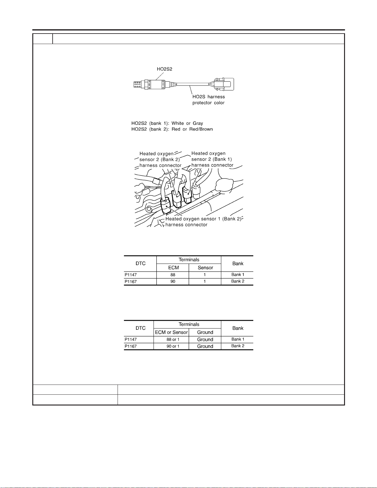
3 CHECK HO2S2 INPUT SIGNAL CIRCUIT FOR OPEN AND SHORT
1. Turn ignition switch “OFF”.
2. Check heated oxygen sensor 2 harness protector color.
SEF372ZB
3. Disconnect corresponding heated oxygen sensor 2 harness connector.
SEC134D
4. Disconnect ECM harness connector.
5. Check harness continuity between ECM terminal and HO2S2 terminal as follows.
Refer to Wiring Diagram.
MTBL1163
Continuity should exist.
6. Check harness continuity between ECM terminal or HO2S2 terminal and ground as follows.
Refer to Wiring Diagram.
MTBL1164
Continuity should not exist.
7. Also check harness for short to power.
OK or NG
OK © GO TO 4.
NG © Repair open circuit or short to ground or short to power in harness or connectors.
DTC P1147, P1167 HO2S2
Diagnostic Procedure (Cont’d)
EC-522
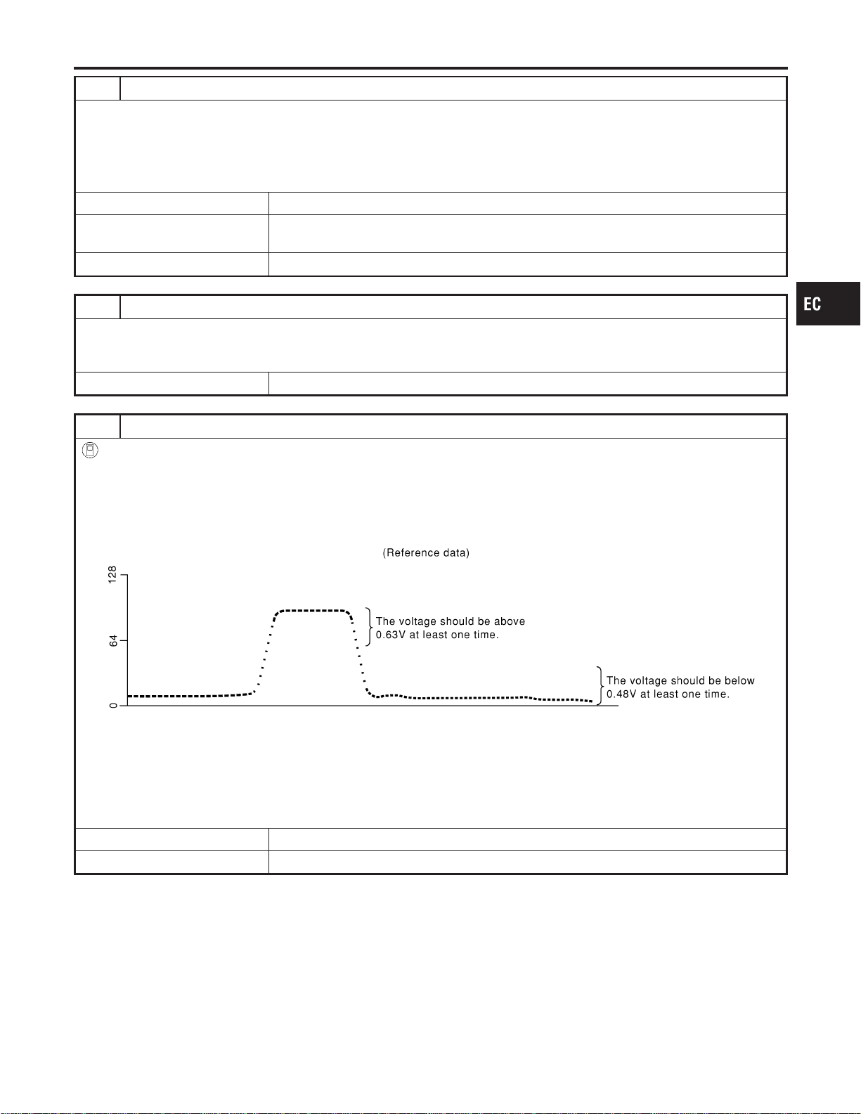
4 CHECK HO2S2 GROUND CIRCUIT FOR OPEN AND SHORT
1. Check harness continuity between HO2S2 terminal 4 and engine ground.
Refer to Wiring Diagram.
Continuity should exist.
2. Also check harness for short to power.
OK or NG
OK (With CONSULT-II) © GO TO 6.
OK (Without CONSULT-
II)
© GO TO 7.
NG © GO TO 5.
5 DETECT MALFUNCTIONING PART
Check the following.
I Joint connectors-18
I Harness for open or short between heated oxygen sensor 2 and ground
© Repair open circuit or short to power in harness or connectors.
6 CHECK HEATED OXYGEN SENSOR 2
With CONSULT-II
1. Start engine and drive vehicle at a speed of more than 70 km/h (43 MPH) for 2 consecutive minutes.
2. Stop vehicle with engine running.
3. Select “FUEL INJECTION” in “ACTIVE TEST” mode, and select “HO2S2 (B1)/(B2)” as the monitor item with CONSULT-
II.
4. Check “HO2S2 (B1)/(B2)” at idle speed when adjusting “FUEL INJECTION” to ±25%.
SEF066YA
“HO2S2 (B1)/(B2)” should be above 0.63V at least once when the “FUEL INJECTION” is +25%.
“HO2S2 (B1)/(B2)” should be below 0.48V at least once when the “FUEL INJECTION” is −25%.
CAUTION:
Discard any heated oxygen sensor which has been dropped from a height of more than 0.5 m (19.7 in) onto a
hard surface such as a concrete floor; use a new one.
OK or NG
OK © GO TO 10.
NG © GO TO 9.
GI
MA
EM
LC
FE
CL
MT
AT
AX
SU
BR
ST
RS
BT
HA
SC
EL
IDX
DTC P1147, P1167 HO2S2
Diagnostic Procedure (Cont’d)
EC-523
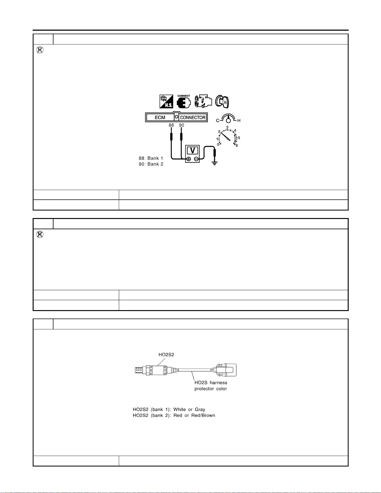
7 CHECK HEATED OXYGEN SENSOR 2-I
Without CONSULT-II
1. Start engine and drive vehicle at a speed of more than 70 km/h (43 MPH) for 2 consecutive minutes.
2. Stop vehicle with engine running.
3. Set voltmeter probes between ECM terminal 88 (HO2S2 bank 1 signal) or 90 (HO2S bank 2 signal) and engine ground.
4. Check the voltage when revving up to 4,000 rpm under no load at least 10 times.
(Depress and release accelerator pedal as soon as possible.)
SEC903C
The voltage should be above 0.63V at least once during this procedure.
OK or NG
OK © GO TO 10.
NG © GO TO 8.
8 CHECK HEATED OXYGEN SENSOR 2-II
Without CONSULT-II
Idle vehicle for 10 minutes, then check voltage between the same terminals as in Test No. 7; or check voltage when coast-
ing from 80 km/h (50 MPH) in 3rd gear position (M/T), “D” position with “OD” OFF (A/T).
The voltage should go below 0.48V at least once during this procedure.
CAUTION:
Discard any heated oxygen sensor which has been dropped from a height of more than 0.5 m (19.7 in) onto a
hard surface such as a concrete floor; use a new one.
OK or NG
OK © GO TO 10.
NG © GO TO 9.
9 REPLACE HEATED OXYGEN SENSOR 2
1. Stop vehicle and turn ignition switch “OFF”.
2. Check heated oxygen sensor 2 harness protector color.
SEF372ZB
CAUTION:
Before installing new oxygen sensor, clean exhaust system threads using Oxygen Sensor Thread Cleaner tool
J-43897-18 or J-43897-12 and approved anti-seize lubricant.
© Replace malfunctioning heated oxygen sensor 2.
DTC P1147, P1167 HO2S2
Diagnostic Procedure (Cont’d)
EC-524
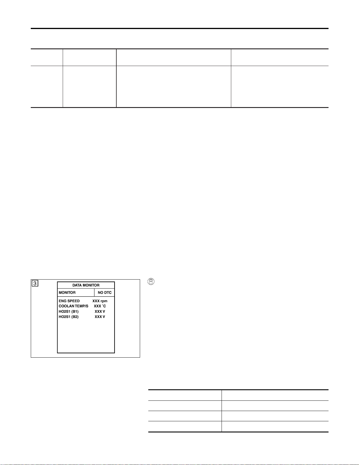
On Board Diagnosis Logic
NFEC1064
★ The closed loop control has the one trip detection logic.
DTC No.
Trouble diagnosis
name
DTC Detecting Condition Possible Cause
P1148
1148
(Bank 1)
P1168
1168
(Bank 2)
Closed loop control The closed loop control function for bank 1 does
not operate even when vehicle is driving in the
specified condition, the closed loop control func-
tion for bank 2 does not operate even when
vehicle is driving in the specified condition.
I The heated oxygen sensor 1 circuit is
open or shorted.
I Heated oxygen sensor 1
I Heated oxygen sensor 1 heater
DTC Confirmation Procedure
NFEC1065
CAUTION:
Always drive vehicle at a safe speed.
NOTE:
If “DTC Confirmation Procedure” has been previously conducted,
always turn ignition switch “OFF” and wait at least 10 seconds
before conducting the next test.
TESTING CONDITION:
I Never raise engine speed above 3,600 rpm during the
“DTC Confirmation Procedure”. If the engine speed limit is
exceeded, retry the procedure from step 2.
I Before performing the following procedure, confirm that
battery voltage is more than 11V at idle.
SEC011C
WITH CONSULT-II
NFEC1065S01
1) Start engine and warm it up to normal operating temperature.
2) Select “DATA MONITOR” mode with CONSULT-II.
3) Hold engine speed at 2,000 rpm and check one of the follow-
ing.
I “HO2S1 (B1)/(B2)” voltage should go above 0.70V at least
once.
I “HO2S1 (B1)/(B2)” voltage should go below 0.21V at least
once.
If the check result is NG, perform “Diagnosis Procedure”,
EC-527.
If the check result is OK, perform the following step.
4) Let engine idle at least 5 minutes.
5) Maintain the following condition at least 50 consecutive sec-
onds.
B/FUEL SCHDL 3.0 msec or more
ENG SPEED 1,800 - 3,000 rpm
Selector lever Suitable position
VHCL SPEED SE More than 70 km/h (43 MPH)
DTC P1148, P1168 CLOSED LOOP CONTROL
On Board Diagnosis Logic
EC-526
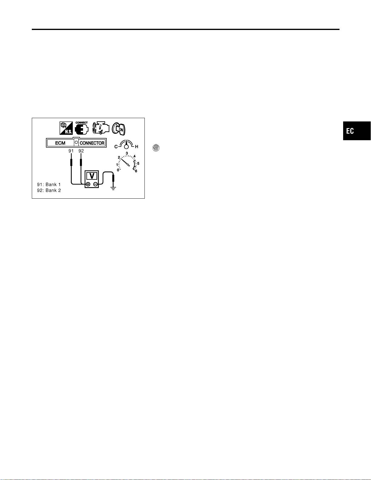
During this test, P0134 and/or P0154 may be displayed on
CONSULT-II screen.
6) If DTC is detected, go to “Diagnostic Procedure”, EC-527.
SEC085D
Overall Function Check
NFEC1066
Use this procedure to check the overall function of the closed loop
control. During this check, a DTC might not be confirmed.
WITH GST
NFEC1066S01
1) Start engine and warm it up to normal operating temperature.
2) Set voltmeter probes between ECM terminal 91 [Heated oxy-
gen sensor 1 bank 1 signal] or 92 [Heated oxygen sensor 1
bank 2 signal] and engine ground.
3) Check the following with engine speed held at 2,000 rpm con-
stant under no-load.
I The voltage should go above 0.70V at least once.
I The voltage should go below 0.21V at least once.
4) If NG, go to “Diagnostic Procedure”, EC-527.
Diagnostic Procedure
NFEC1067
Perform trouble diagnosis for “DTC P0133, P0153”, EC-228.
GI
MA
EM
LC
FE
CL
MT
AT
AX
SU
BR
ST
RS
BT
HA
SC
EL
IDX
DTC P1148, P1168 CLOSED LOOP CONTROL
DTC Confirmation Procedure (Cont’d)
EC-527
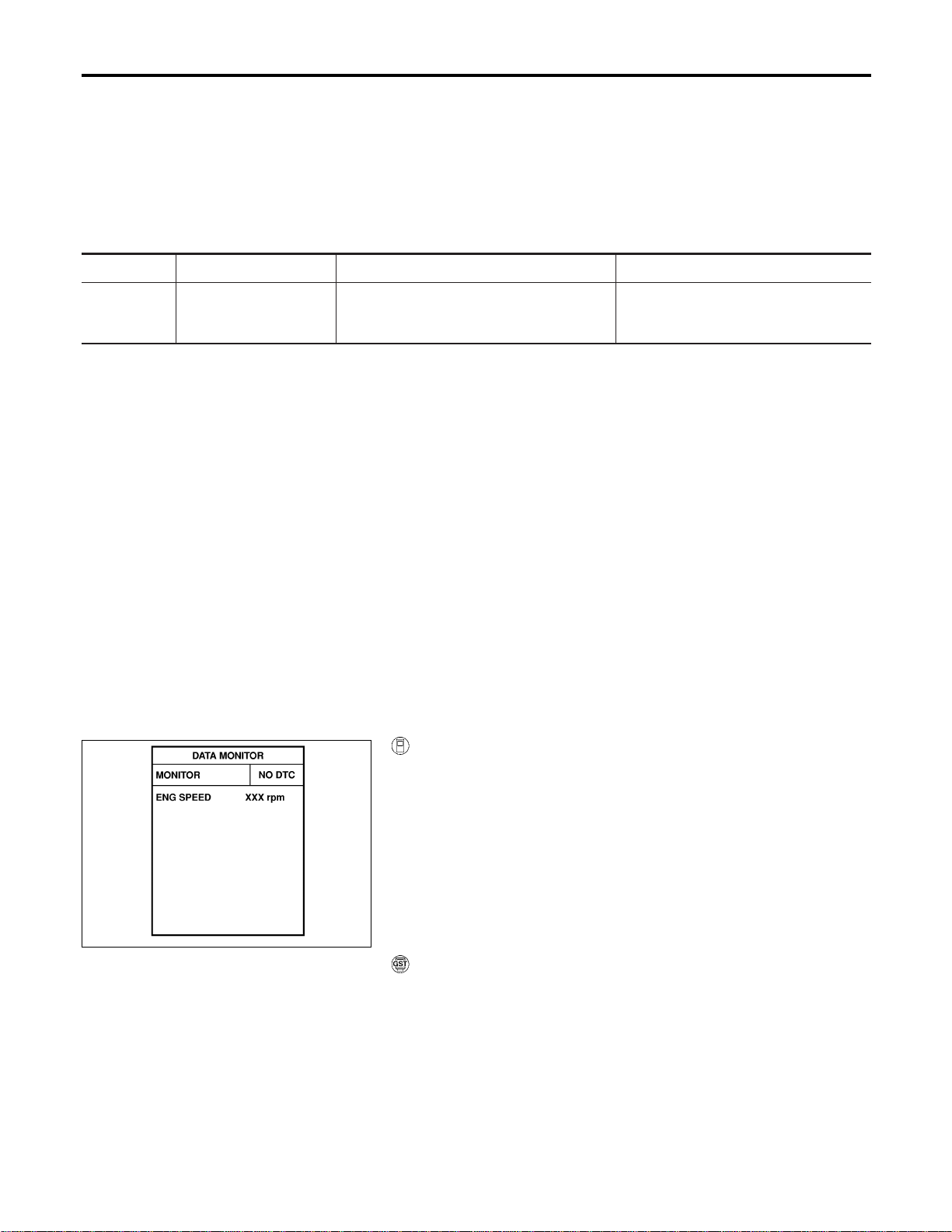
Description
NFEC1268
The malfunction information related to ABS or ABS/TCS is transferred through the CAN communication line
from ABS actuator and electric unit or ABS/TCS control unit to ECM.
Be sure to erase the malfunction information such as DTC not only for ABS actuator and electric unit
or ABS/TCS control unit but also for ECM after the ABS or ABS/TCS related repair.
On Board Diagnosis Logic
NFEC1269
Freeze frame data is not stored in the ECM for this self-diagnosis. The MIL will not light up for this
self-diagnosis.
DTC No. Trouble diagnosis name DTC detecting condition Possible cause
P1211
1211
ABS/TCS control unit
performance
ECM receives a malfunction information from
ABS actuator and electric unit or ABS/TCS
control unit.
I ABS actuator and electric unit
I ABS/TCS control unit
I TCS related parts
DTC Confirmation Procedure
NFEC1270
TESTING CONDITION:
Before performing the following procedure, confirm that bat-
tery voltage is more than 10.5V at idle.
SEF058Y
With CONSULT-II
1. Turn ignition switch “ON”.
2. Select “DATA MONITOR” mode with CONSULT-II.
3. Start engine and let it idle for at least 60 seconds.
4. If 1st trip DTC is detected, go to “Diagnostic Procedure”,
EC-529.
WITH GST
Follow the procedure “WITH CONSULT-II” above.
DTC P1211 ABS/TCS CONTROL UNIT
Description
EC-528

Diagnostic Procedure
NFEC1272
Go to BR-56 (With ABS models) or BR-102 (With ABS/TCS
models), “TROUBLE DIAGNOSIS — INTRODUCTION”.
GI
MA
EM
LC
FE
CL
MT
AT
AX
SU
BR
ST
RS
BT
HA
SC
EL
IDX
DTC P1211 ABS/TCS CONTROL UNIT
Diagnostic Procedure
EC-529
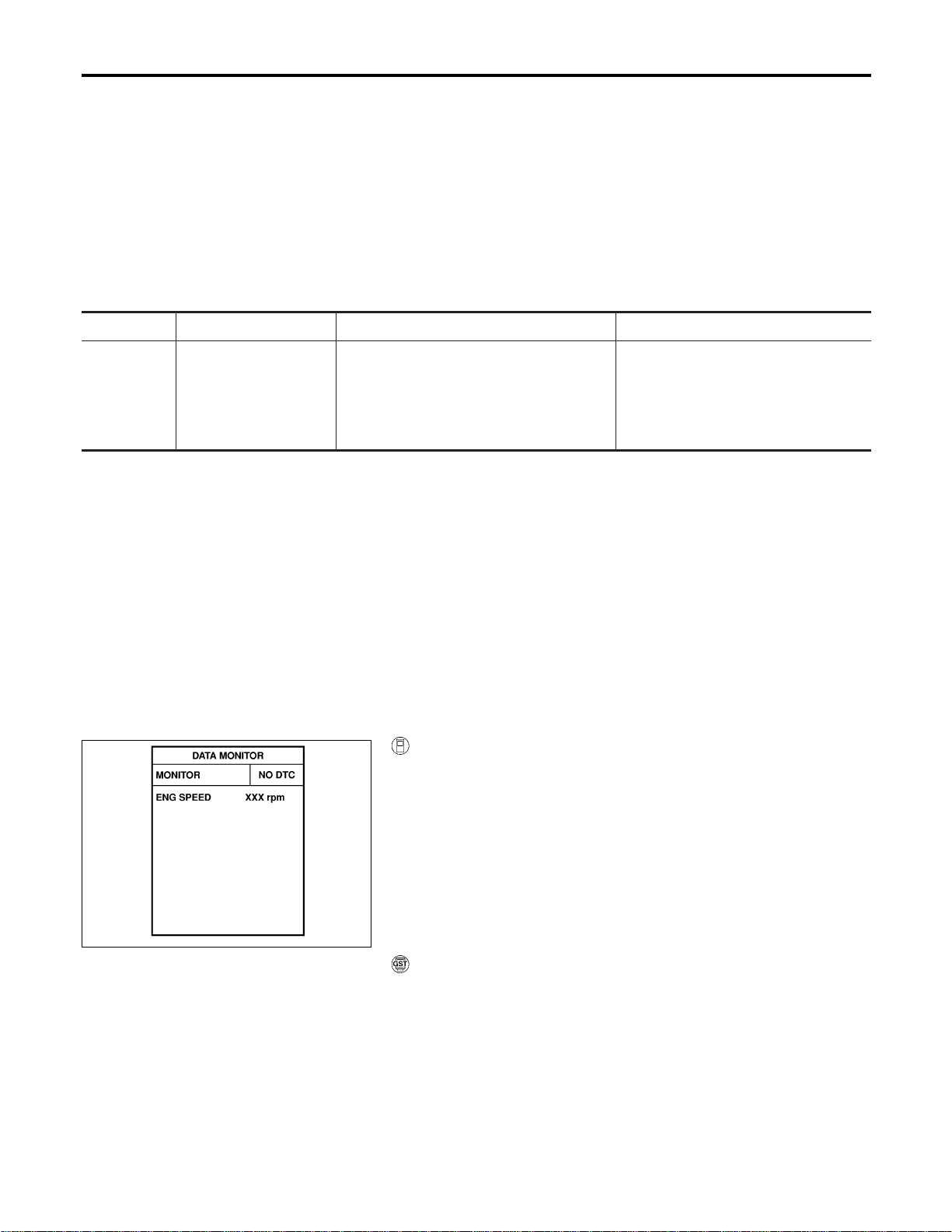
Description
NFEC1273
NOTE:
If DTC P1212 is displayed with DTC U1000, U1001, first perform the trouble diagnosis for DTC U1000,
U1001. Refer to “DTC U1000, U1001 CAN COMMUNICATION LINE”, EC-164.
This CAN communication line is used to control the smooth engine operation during the ABS or TCS opera-
tion. Pulse signals are exchanged between ECM and ABS actuator and electric unit or ABS/TCS control unit.
Be sure to erase the malfunction information such as DTC not only in ABS actuator and electric unit
or ABS/TCS control unit but also ECM after the ABS or ABS/TCS related repair.
On Board Diagnosis Logic
NFEC1274
Freeze frame data is not stored in the ECM for this self-diagnosis. The MIL will not light up for this
self-diagnosis.
DTC No. Trouble diagnosis name DTC detecting condition Possible cause
P1212
1212
ABS/TCS communication
line
ECM cannot receive the information from
ABS actuator and electric unit or ABS/TCS
control unit continuously.
I Harness or connectors
(The CAN communication line is open
or shorted.)
I ABS actuator and electric unit
I ABS/TCS control unit
I Dead (Weak) battery
DTC Confirmation Procedure
NFEC1275
TESTING CONDITION:
Before performing the following procedure, confirm that bat-
tery voltage is more than 10.5V at idle.
SEF058Y
WITH CONSULT-II
1. Turn ignition switch “ON”.
2. Select “DATA MONITOR” mode with CONSULT-II.
3. Start engine and let it idle for at least 10 seconds.
4. If 1st trip DTC is detected, go to “Diagnostic Procedure”,
EC-531.
WITH GST
Follow the procedure “WITH CONSULT-II” above.
DTC P1212 ABS/TCS COMMUNICATION LINE
Description
EC-530
Diagnostic Procedure
NFEC1277
1 CHECK ABS/TCS CONTROL UNIT FUNCTION
Refer to “TROUBLE DIAGNOSIS — INTRODUCTION”, BR-56 (With ABS models) or BR-102 (With ABS/TCS models).
© INSPECTION END
GI
MA
EM
LC
FE
CL
MT
AT
AX
SU
BR
ST
RS
BT
HA
SC
EL
IDX
DTC P1212 ABS/TCS COMMUNICATION LINE
Diagnostic Procedure
EC-531
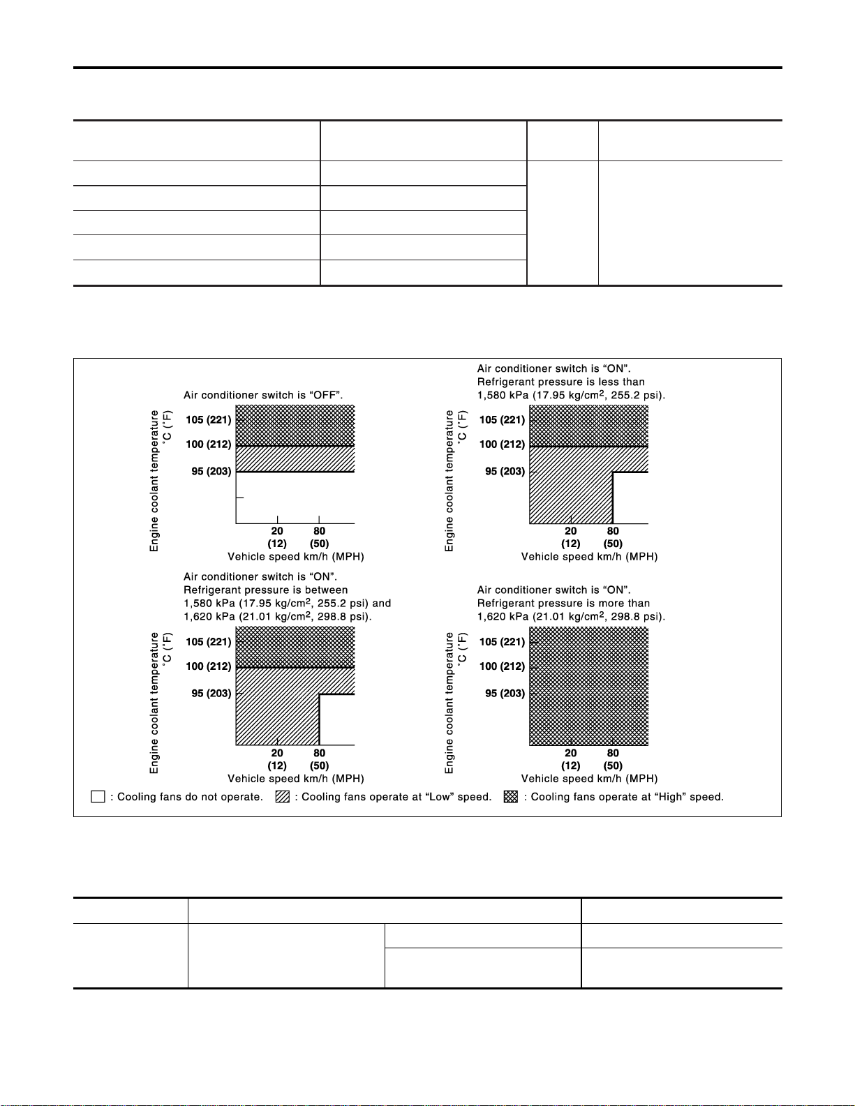
System Description
NFEC1320
COOLING FAN CONTROL
NFEC1320S01
Sensor Input Signal to ECM
ECM func-
tion
Actuator
Wheel sensor Vehicle speed
Cooling fan
control
Cooling fan relay(s)
Engine coolant temperature sensor Engine coolant temperature
Air conditioner switch Air conditioner “ON” signal
Ignition switch Start signal
Refrigerant pressure sensor Refrigerant pressure
The ECM controls the cooling fan corresponding to the vehicle speed, engine coolant temperature, refriger-
ant pressure and air conditioner ON signal. The control system has 3-step control [HIGH/LOW/OFF].
OPERATION
NFEC1320S02
SEC925C
CONSULT-II Reference Value in Data Monitor
Mode
NFEC1321
Specification data are reference values.
MONITOR ITEM CONDITION SPECIFICATION
AIR COND SIG
I Engine: After warming up, idle
the engine
Air conditioner switch: OFF OFF
Air conditioner switch: ON
(Compressor operates)
ON
DTC P1217 ENGINE OVER TEMPERATURE
System Description
EC-532
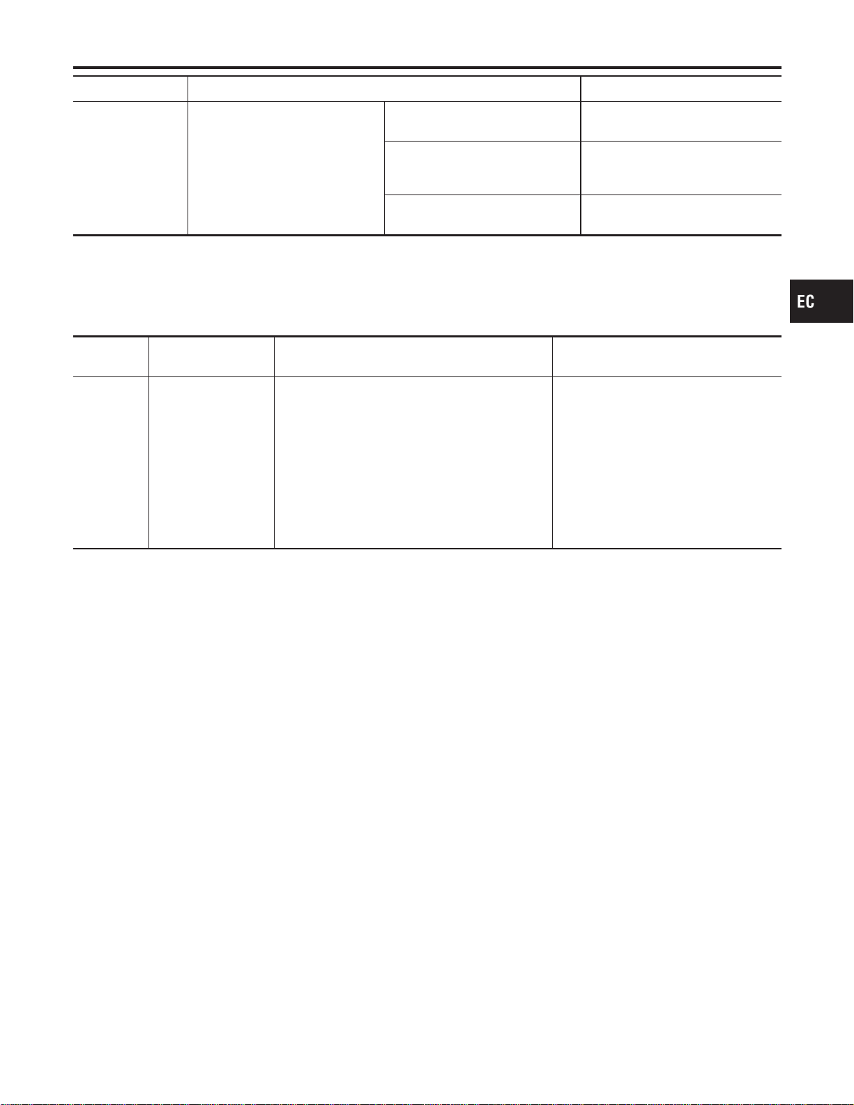
MONITOR ITEM CONDITION SPECIFICATION
COOLING FAN
I After warming up engine, idle
the engine.
I Air conditioner switch: OFF
Engine coolant temperature is
94°C (201°F) or less
OFF
Engine coolant temperature is
between 95°C (203°F) and 99°C
(210°F)
LOW
Engine coolant temperature is
100°C (212°F) or more
HIGH
On Board Diagnosis Logic
NFEC1454
If the cooling fan or another component in the cooling system malfunctions, engine coolant temperature will
rise.
When the engine coolant temperature reaches an abnormally high temperature condition, a malfunction is
indicated.
DTC No.
Trouble diagnosis
name
DTC Detecting Condition Possible Cause
P1217
1217
Engine over tempera-
ture
I Cooling fan does not operate properly (Over-
heat).
I Cooling fan system does not operate properly
(Overheat).
I Engine coolant was not added to the system
using the proper filling method.
I Harness or connectors (The cooling
fan circuit is open or shorted.)
I Cooling fan
I Radiator hose
I Radiator
I Radiator cap
I Water pump
I Thermostat
For more information, refer to “MAIN
12 CAUSES OF OVERHEATING”,
EC-549.
CAUTION:
When a malfunction is indicated, be sure to replace the coolant following the procedure in the MA-14,
“Changing Engine Coolant”. Also, replace the engine oil.
1) Fill radiator with coolant up to specified level with a filling speed of 2 liters per minute. Be sure
to use coolant with the proper mixture ratio. Refer to MA-12, “Anti-freeze Coolant Mixture Ratio”.
2) After refilling coolant, run engine to ensure that no water-flow noise is emitted.
GI
MA
EM
LC
FE
CL
MT
AT
AX
SU
BR
ST
RS
BT
HA
SC
EL
IDX
DTC P1217 ENGINE OVER TEMPERATURE
CONSULT-II Reference Value in Data Monitor Mode (Cont’d)
EC-533
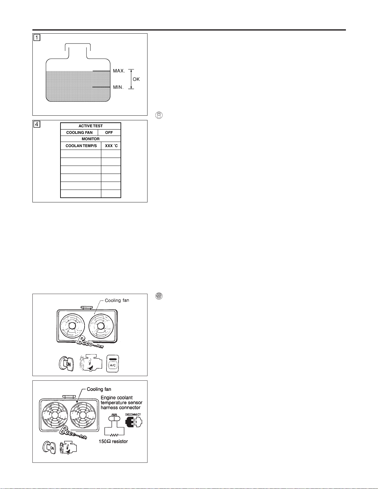
SEF621W
SEF111X
Overall Function Check
NFEC1324
Use this procedure to check the overall function of the cooling fan.
During this check, a DTC might not be confirmed.
WARNING:
Never remove the radiator cap when the engine is hot. Serious
burns could be caused by high pressure fluid escaping from
the radiator.
Wrap a thick cloth around cap. Carefully remove the cap by
turning it a quarter turn to allow built-up pressure to escape.
Then turn the cap all the way off.
WITH CONSULT-II
NFEC1324S01
1) Check the coolant level in the reservoir tank and radiator.
Allow engine to cool before checking coolant level.
If the coolant level in the reservoir tank and/or radiator is below
the proper range, skip the following steps and go to “Diagnos-
tic Procedure”, EC-538.
2) Confirm whether customer filled the coolant or not. If customer
filled the coolant, skip the following steps and go to “Diagnos-
tic Procedure”, EC-538.
3) Turn ignition switch “ON”.
4) Perform “COOLING FAN” in “ACTIVE TEST” mode with CON-
SULT-II.
5) If the results are NG, go to “Diagnostic Procedure”, EC-538.
SEC163BA
MEC475B
WITH GST
NFEC1324S03
1) Check the coolant level in the reservoir tank and radiator.
Allow engine to cool before checking coolant level.
If the coolant level in the reservoir tank and/or radiator is below
the proper range, skip the following steps and go to “Diagnos-
tic Procedure”, EC-538.
2) Confirm whether customer filled the coolant or not. If customer
filled the coolant, skip the following steps and go to “Diagnos-
tic Procedure”, EC-538.
3) Start engine.
Be careful not to overheat engine.
4) Set temperature control lever to full cold position.
5) Turn air conditioner switch “ON”.
6) Turn blower fan switch “ON”.
7) Run engine at idle for a few minutes with air conditioner oper-
ating.
Be careful not to overheat engine.
8) Make sure that cooling fan operates at low speed.
If NG, go to “Diagnostic Procedure”, EC-538.
If OK, go to the following step.
9) Turn ignition switch “OFF”.
10) Turn air conditioner switch and blower fan switch “OFF”.
DTC P1217 ENGINE OVER TEMPERATURE
Overall Function Check
EC-534

11) Disconnect engine coolant temperature sensor harness con-
nector.
12) Connect 150Ω resistor to engine coolant temperature sensor
harness connector.
13) Restart engine and make sure that cooling fan operates at
higher speed than low speed.
Be careful not to overheat engine.
14) If NG, go to “Diagnostic Procedure”, EC-538.
GI
MA
EM
LC
FE
CL
MT
AT
AX
SU
BR
ST
RS
BT
HA
SC
EL
IDX
DTC P1217 ENGINE OVER TEMPERATURE
Overall Function Check (Cont’d)
EC-535

Wiring Diagram
NFEC1325
MEC490D
DTC P1217 ENGINE OVER TEMPERATURE
Wiring Diagram
EC-536
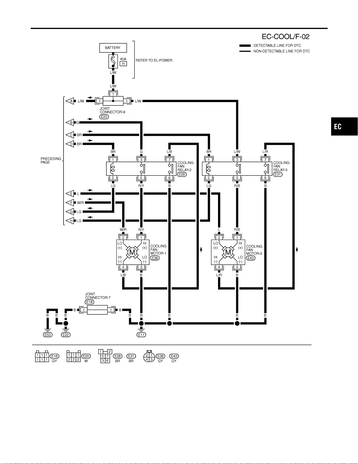
MEC491D
GI
MA
EM
LC
FE
CL
MT
AT
AX
SU
BR
ST
RS
BT
HA
SC
EL
IDX
DTC P1217 ENGINE OVER TEMPERATURE
Wiring Diagram (Cont’d)
EC-537
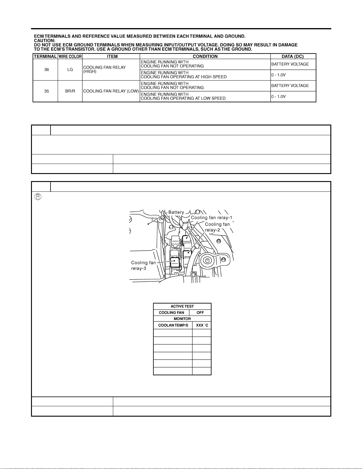
SEF630XC
Diagnostic Procedure
NFEC1326
1 INSPECTION START
Do you have CONSULT-II?
YesorNo
Yes © GO TO 2.
No © GO TO 4.
2 CHECK COOLING FAN LOW SPEED OPERATION
With CONSULT-II
1. Disconnect cooling fan relays-2 and -3.
SEC006C
2. Turn ignition switch “ON”.
3. Perform “COOLING FAN” in “ACTIVE TEST” mode with CONSULT-II.
SEF646X
4. Make sure that cooling fans-1 and -2 operate at low speed.
OK or NG
OK © GO TO 3.
NG © Check cooling fan low speed control circuit. (Go to PROCEDURE A, EC-544.)
DTC P1217 ENGINE OVER TEMPERATURE
Wiring Diagram (Cont’d)
EC-538
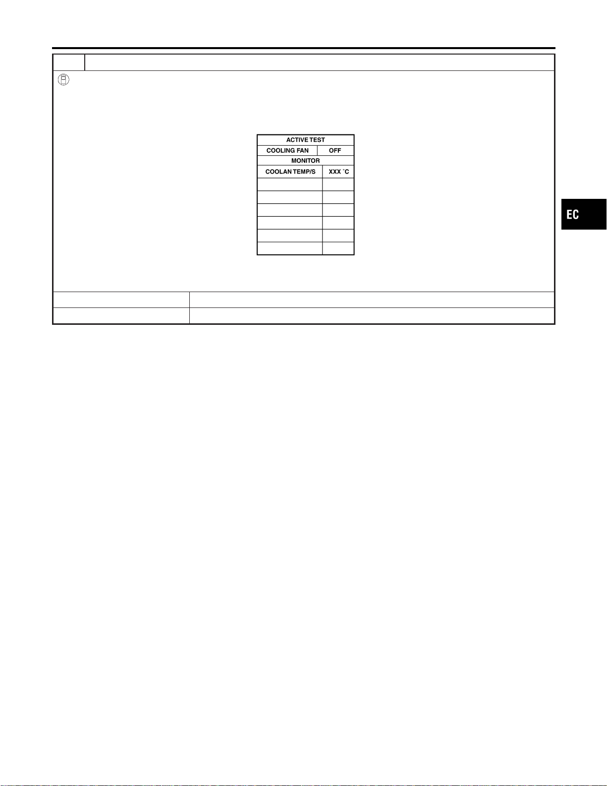
3 CHECK COOLING FAN HIGH SPEED OPERATION
With CONSULT-II
1. Turn ignition switch “OFF”.
2. Reconnect cooling fan relays-2 and -3.
3. Turn ignition switch “ON”.
4. Perform “COOLING FAN” in “ACTIVE TEST” mode with CONSULT-II.
SEF111X
5. Make sure that cooling fans-1 and -2 operate at high speed.
OK or NG
OK © GO TO 6.
NG © Check cooling fan high speed control circuit. (Go to PROCEDURE B, EC-547.)
GI
MA
EM
LC
FE
CL
MT
AT
AX
SU
BR
ST
RS
BT
HA
SC
EL
IDX
DTC P1217 ENGINE OVER TEMPERATURE
Diagnostic Procedure (Cont’d)
EC-539
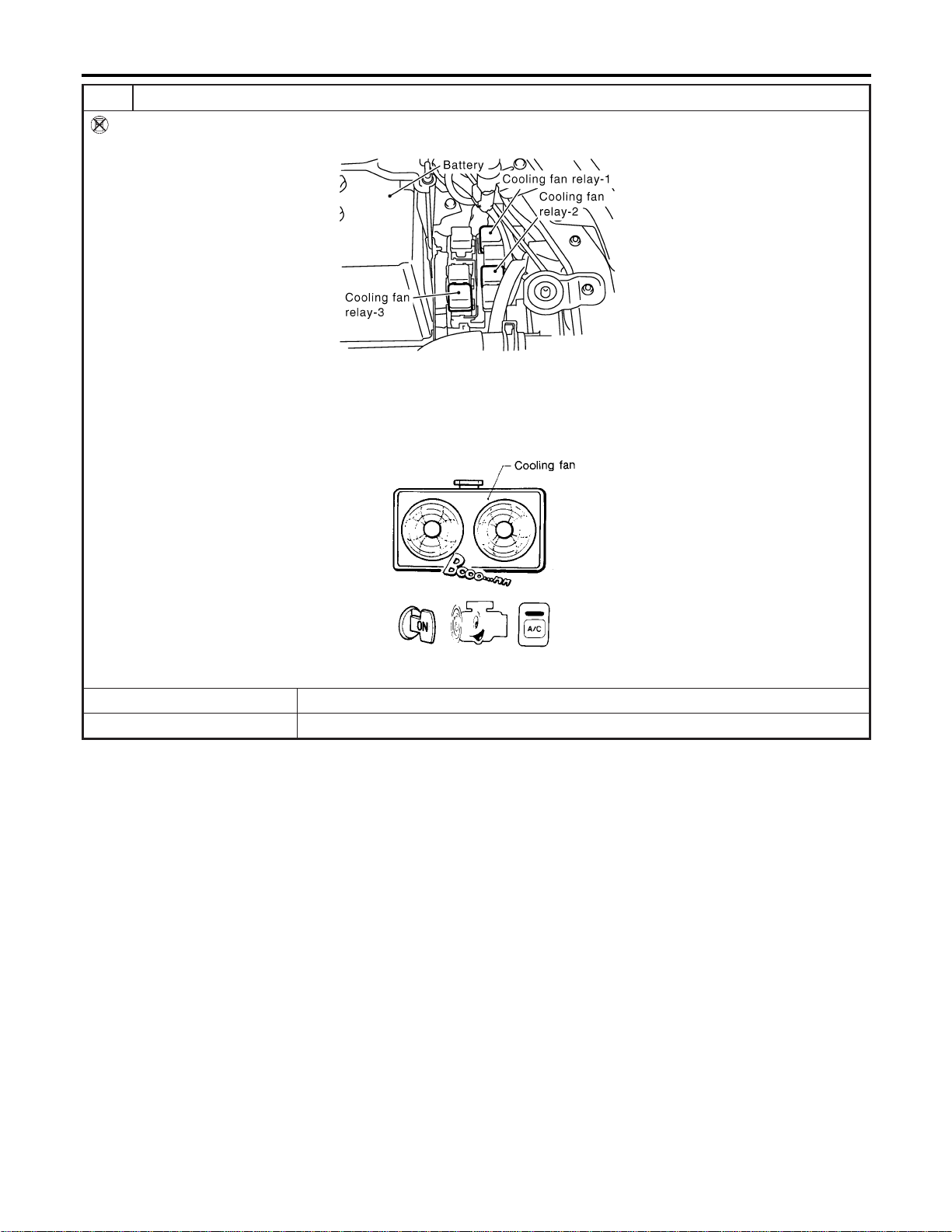
4 CHECK COOLING FAN LOW SPEED OPERATION
Without CONSULT-II
1. Disconnect cooling fan relays-2 and -3.
SEC006C
2. Start engine and let it idle.
3. Set temperature lever at full cold position.
4. Turn air conditioner switch “ON”.
5. Turn blower fan switch “ON”.
6. Make sure that cooling fans-1 and -2 operate at low speed.
SEC163BA
OK or NG
OK © GO TO 5.
NG © Check cooling fan low speed control circuit. (Go to PROCEDURE A, EC-544.)
DTC P1217 ENGINE OVER TEMPERATURE
Diagnostic Procedure (Cont’d)
EC-540
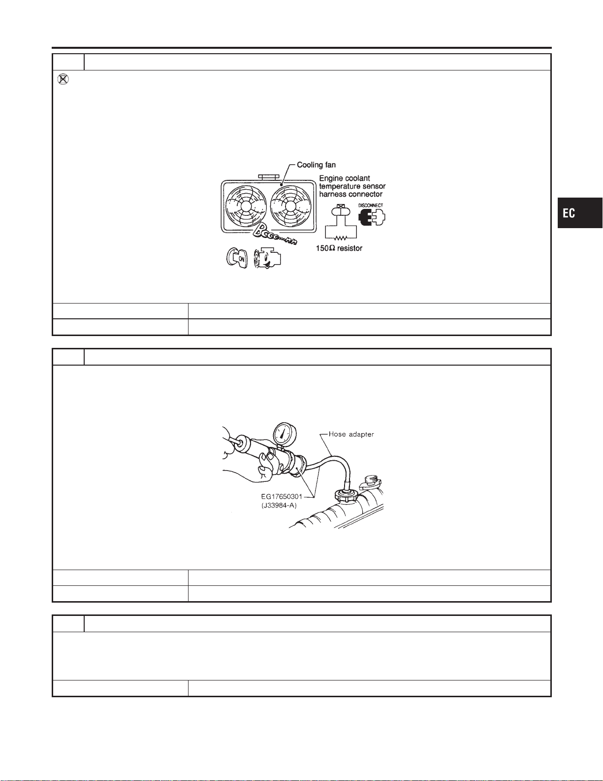
5 CHECK COOLING FAN HIGH SPEED OPERATION
Without CONSULT-II
1. Turn ignition switch “OFF”.
2. Reconnect cooling fan relays-2 and -3.
3. Turn air conditioner switch and blower fan switch “OFF”.
4. Disconnect engine coolant temperature sensor harness connector.
5. Connect 150Ω resistor to engine coolant temperature sensor harness connector.
6. Restart engine and make sure that cooling fans-1 and -2 operate at high speed.
MEC475B
OK or NG
OK © GO TO 6.
NG © Check cooling fan high speed control circuit. (Go to PROCEDURE B, EC-547.)
6 CHECK COOLING SYSTEM FOR LEAK
Apply pressure to the cooling system with a tester, and check if the pressure drops.
Testing pressure: 157 kPa (1.6 kg/cm
2
, 23 psi)
CAUTION:
Higher than the specified pressure may cause radiator damage.
SLC754A
Pressure should not drop.
OK or NG
OK © GO TO 8.
NG © GO TO 7.
7 DETECT MALFUNCTIONING PART
Check the following for leak.
I Hose
I Radiator
I Water pump (Refer to LC-14, “Water Pump”.)
© Repair or replace.
GI
MA
EM
LC
FE
CL
MT
AT
AX
SU
BR
ST
RS
BT
HA
SC
EL
IDX
DTC P1217 ENGINE OVER TEMPERATURE
Diagnostic Procedure (Cont’d)
EC-541
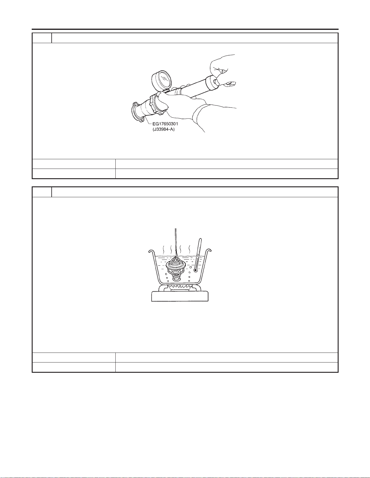
8 CHECK RADIATOR CAP
Apply pressure to cap with a tester and check radiator cap relief pressure.
SLC755A
Radiator cap relief pressure:
59 - 98 kPa (0.6 - 1.0 kg/cm
2
,9-14psi)
OK or NG
OK © GO TO 9.
NG © Replace radiator cap.
9 CHECK THERMOSTAT
1. Remove thermostat.
2. Check valve seating condition at normal room temperatures.
It should seat tightly.
3. Check valve opening temperature and valve lift.
SLC343
Valve opening temperature:
82°C (180°F) [standard]
Valve lift:
More than 8.6 mm/95°C (0.339 in/203°F)
4. Check if valve is closed at 5°C (9°F) below valve opening temperature. For details, refer to LC-18, “Thermostat”.
OK or NG
OK © GO TO 10.
NG © Replace thermostat.
DTC P1217 ENGINE OVER TEMPERATURE
Diagnostic Procedure (Cont’d)
EC-542
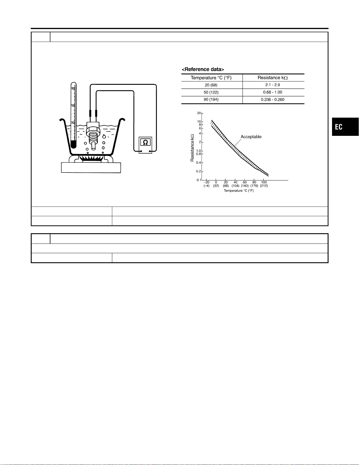
10 CHECK ENGINE COOLANT TEMPERATURE SENSOR
1. Remove engine coolant temperature sensor.
2. Check resistance between engine coolant temperature sensor terminals 1 and 2 as shown in the figure.
SEF304X
OK or NG
OK © GO TO 11.
NG © Replace engine coolant temperature sensor.
11 CHECK MAIN 12 CAUSES
If the cause cannot be isolated, go to “MAIN 12 CAUSES OF OVERHEATING”, EC-549.
© INSPECTION END
GI
MA
EM
LC
FE
CL
MT
AT
AX
SU
BR
ST
RS
BT
HA
SC
EL
IDX
DTC P1217 ENGINE OVER TEMPERATURE
Diagnostic Procedure (Cont’d)
EC-543
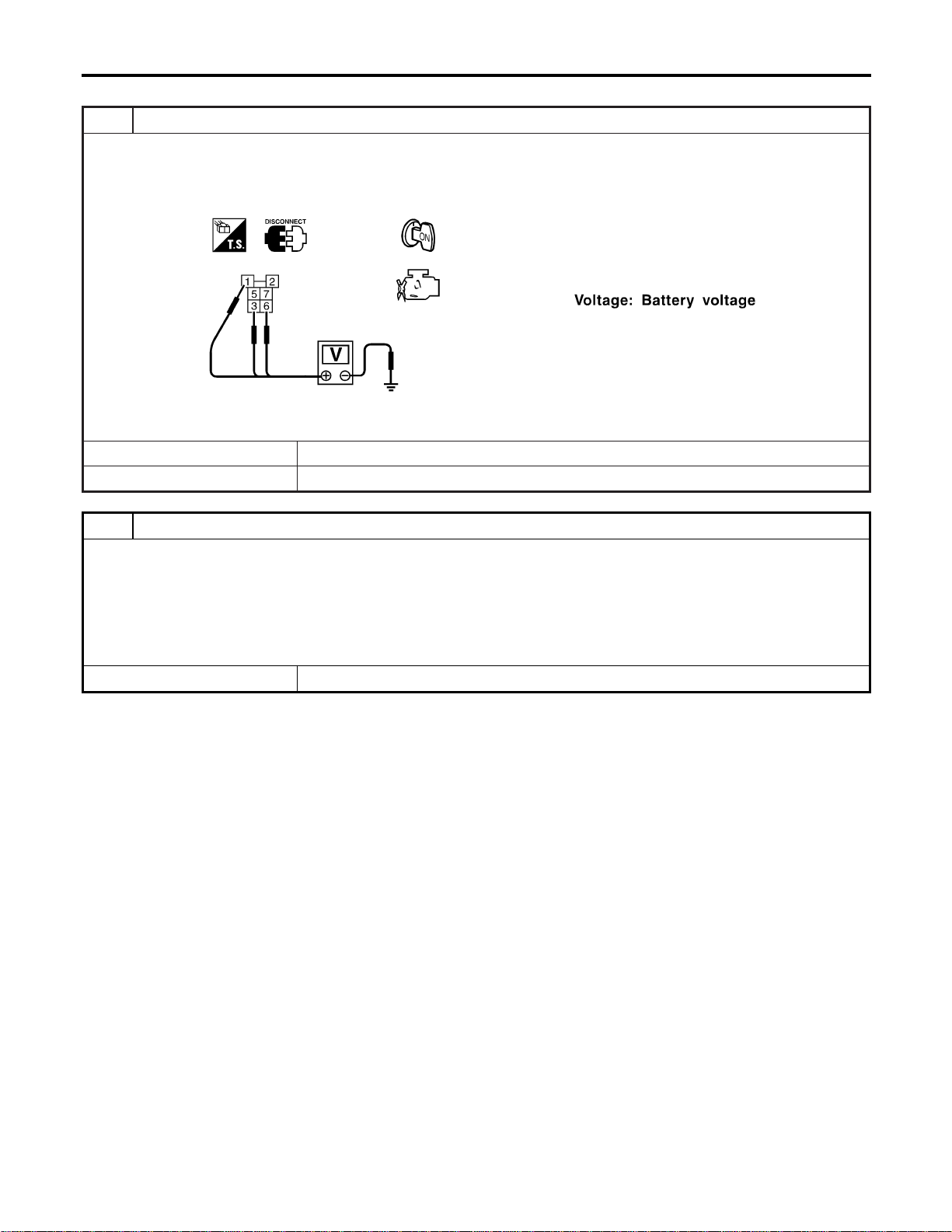
PROCEDURE A
=NFEC1326S01
1 CHECK COOLING FAN POWER SUPPLY CIRCUIT
1. Turn ignition switch “OFF”.
2. Disconnect cooling fan relay-1.
3. Turn ignition switch “ON”.
4. Check voltage between cooling fan relay-1 terminals 1, 3, 6 and ground with CONSULT-II or tester.
SEF590X
OK or NG
OK © GO TO 3.
NG © GO TO 2.
2 DETECT MALFUNCTIONING PART
Check the following.
I Joint connector-8
I Joint connector-9
I 15A fuse
I 40A fusible links
I Harness for open or short between cooling fan relay-1 and fuse
I Harness for open or short between cooling fan relay-1 and battery
© Repair open circuit or short to ground or short to power in harness or connectors.
DTC P1217 ENGINE OVER TEMPERATURE
Diagnostic Procedure (Cont’d)
EC-544
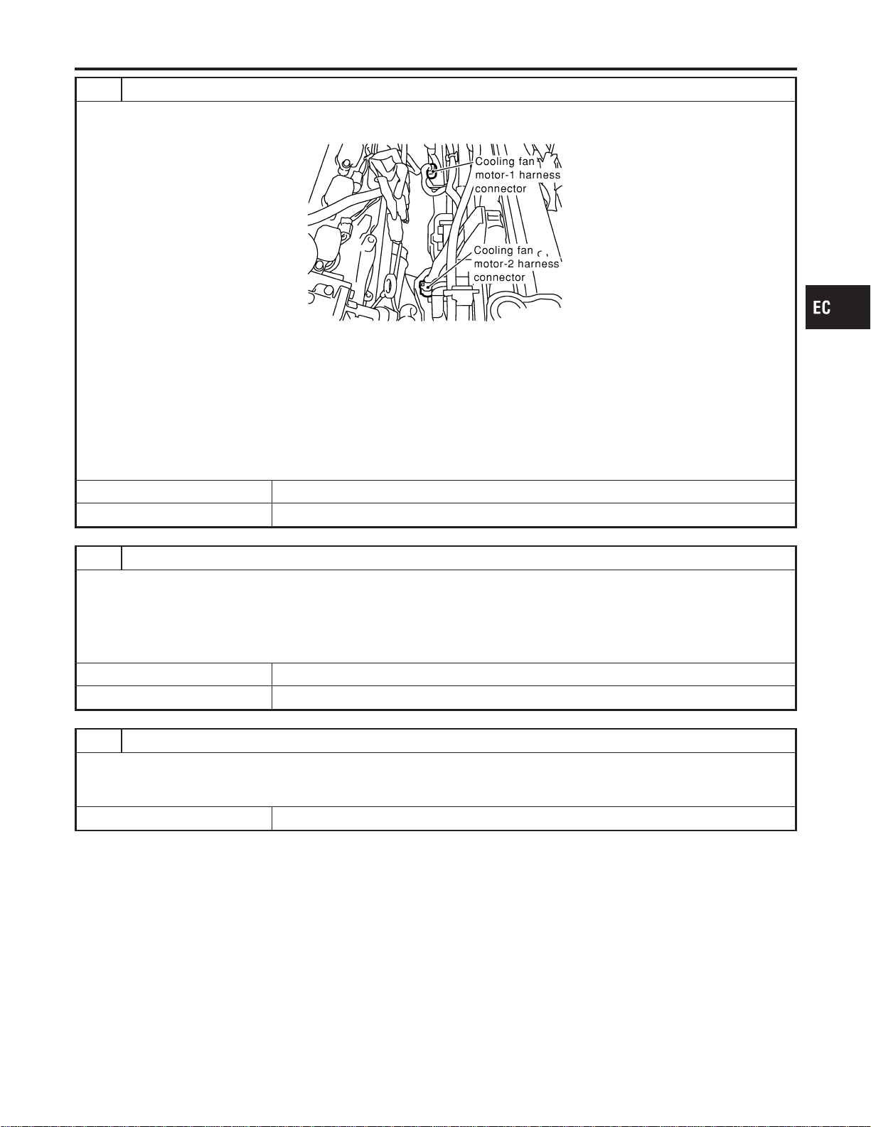
3 CHECK COOLING FAN MOTORS CIRCUIT
1. Turn ignition switch “OFF”.
2. Disconnect cooling fan motor-1 harness connector and cooling fan motor-2 harness connector.
SEC057D
3. Check harness continuity between cooling fan relay-1 terminal 5 and cooling fan motor-1 terminal 2, cooling fan
motor-1 terminal 3 and body ground. Refer to Wiring Diagram.
Continuity should exist.
4. Also check harness for short to ground and short to power.
5. Check harness continuity between cooling fan relay-1 terminal 7 and cooling fan motor-2 terminal 2, cooling fan
motor-2 terminal 3 and body ground. Refer to Wiring Diagram.
Continuity should exist.
6. Also check harness for short to ground and short to power.
OK or NG
OK © GO TO 4.
NG © Repair open circuit or short to ground or short to power in harness or connectors.
4 CHECK COOLING FAN OUTPUT SIGNAL CIRCUIT FOR OPEN AND SHORT
1. Disconnect ECM harness connector.
2. Check harness continuity between ECM terminal 35 and cooling fan relay-1 terminal 2. Refer to Wiring Diagram.
Continuity should exist.
3. Also check harness for short to ground and short to power.
OK or NG
OK © GO TO 6.
NG © GO TO 5.
5 DETECT MALFUNCTIONING PART
Check the following.
I Harness connectors E8, F17
I Harness for open or short between cooling fan relay-1 and ECM
© Repair open circuit or short to ground or short to power in harness or connectors.
GI
MA
EM
LC
FE
CL
MT
AT
AX
SU
BR
ST
RS
BT
HA
SC
EL
IDX
DTC P1217 ENGINE OVER TEMPERATURE
Diagnostic Procedure (Cont’d)
EC-545
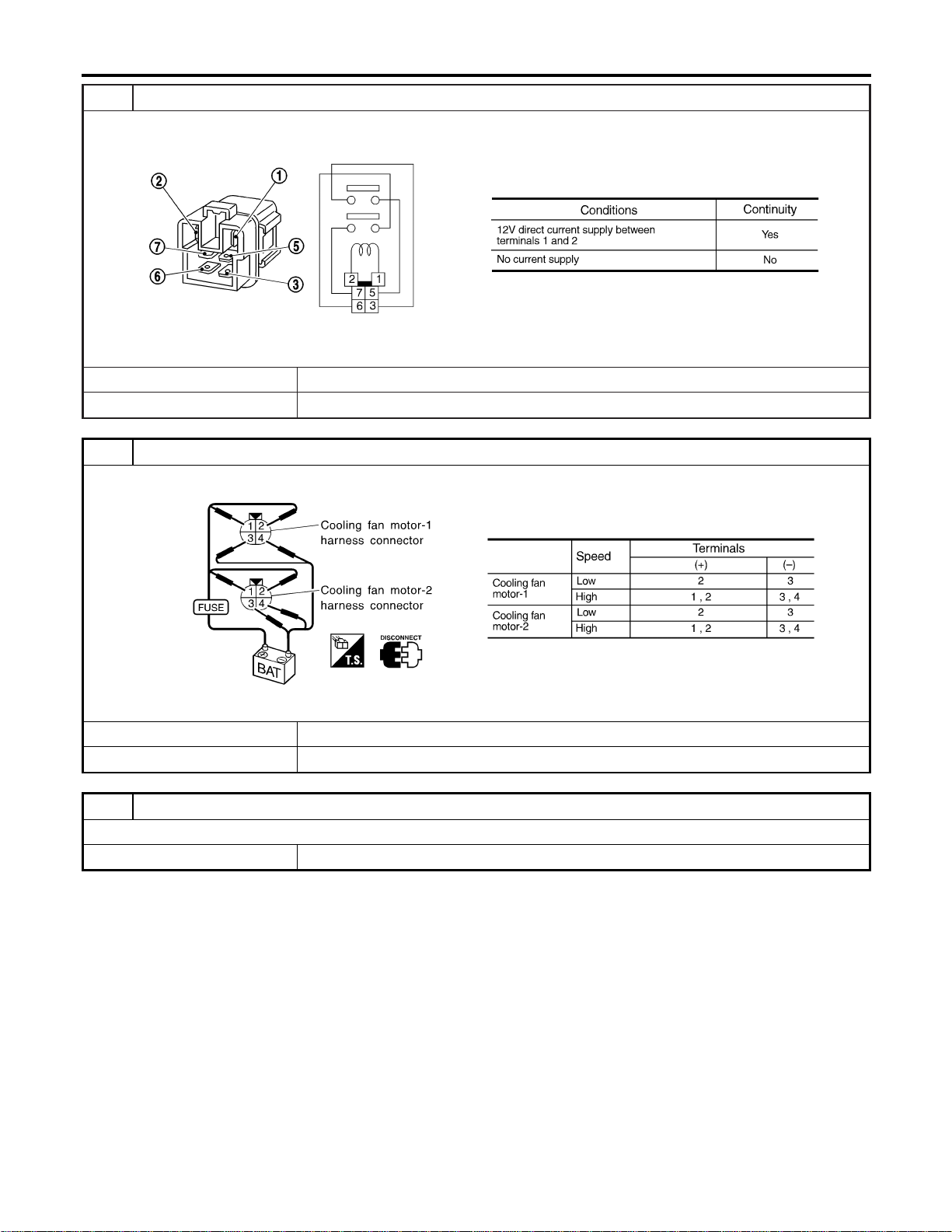
6 CHECK COOLING FAN RELAY-1
Check continuity between cooling fan relay-1 terminals 3 and 5, 6 and 7 under the following conditions.
SEF591X
OK or NG
OK © GO TO 7.
NG © Replace cooling fan relay.
7 CHECK COOLING FAN MOTORS-1 AND -2
Supply battery voltage between the following terminals and check operation.
SEF592X
OK or NG
OK © GO TO 8.
NG © Replace cooling fan motors.
8 CHECK INTERMITTENT INCIDENT
Perform “TROUBLE DIAGNOSIS FOR INTERMITTENT INCIDENT”, EC-156.
© INSPECTION END
DTC P1217 ENGINE OVER TEMPERATURE
Diagnostic Procedure (Cont’d)
EC-546
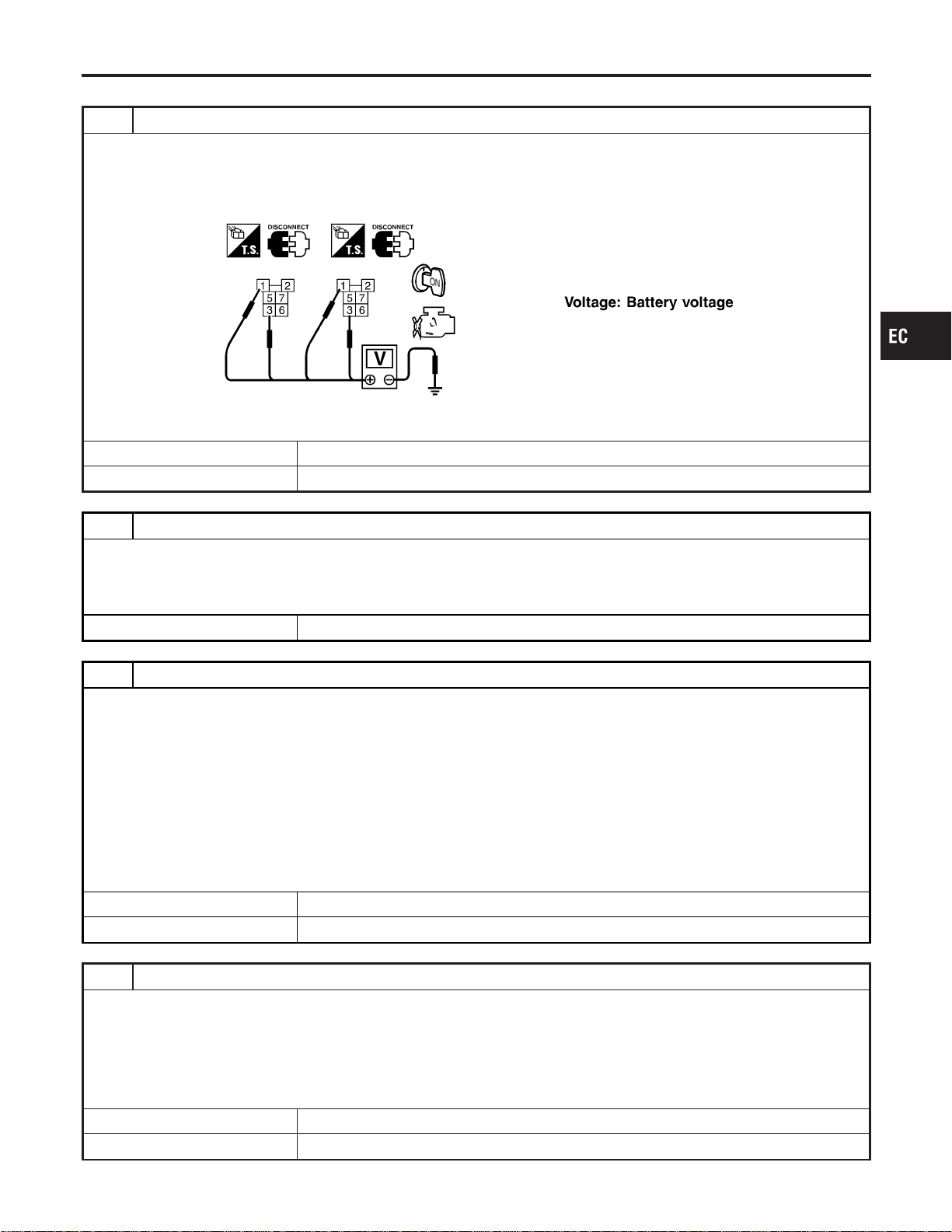
PROCEDURE B
NFEC1326S02
1 CHECK COOLING FAN POWER SUPPLY CIRCUIT
1. Turn ignition switch “OFF”.
2. Disconnect cooling fan relays-2 and -3.
3. Turn ignition switch “ON”.
4. Check voltage between cooling fan relays-2 and -3 terminals 1, 3 and ground with CONSULT-II or tester.
SEF593X
OK or NG
OK © GO TO 3.
NG © GO TO 2.
2 DETECT MALFUNCTIONING PART
Check the following.
I Joint connector-8
I Joint connector-9
I Harness for open or short between cooling fan relays-2 and -3 and joint connectors-8, -9
© Repair harness or connectors.
3 CHECK COOLING FAN CIRCUIT FOR OPEN AND SHORT
1. Turn ignition switch “OFF”.
2. Disconnect cooling fan motor-1 harness connector and cooling fan motor-2 harness connector.
3. Check harness continuity between cooling fan relay-2 terminal 5 and cooling fan motor-1 terminal 1, cooling fan relay-2
terminal 7 and cooling fan motor-1 terminal 4, cooling fan relay-2 terminal 6 and body ground. Refer to Wiring Diagram.
Continuity should exist.
4. Also check harness for short to ground and short to power.
5. Check harness continuity between cooling fan relay-3 terminal 5 and cooling fan motor-2 terminal 1, cooling fan relay-3
terminal 7 and cooling fan motor-2 terminal 4, cooling fan relay-3 terminal 6 and body ground. Refer to Wiring Diagram.
Continuity should exist.
6. Also check harness for short to ground and short to power.
OK or NG
OK © GO TO 4.
NG © Repair open circuit or short to ground or short to power in harness or connectors.
4 CHECK COOLING FAN OUTPUT SIGNAL CIRCUIT FOR OPEN AND SHORT
1. Disconnect ECM harness connector.
2. Check harness continuity between ECM terminal 36 and cooling fan relay-2 terminal 2, cooling fan relay-3 terminal 2.
Refer to Wiring Diagram.
Continuity should exist.
3. Also check harness for short to ground and short to power.
OK or NG
OK © GO TO 6.
NG © GO TO 5.
GI
MA
EM
LC
FE
CL
MT
AT
AX
SU
BR
ST
RS
BT
HA
SC
EL
IDX
DTC P1217 ENGINE OVER TEMPERATURE
Diagnostic Procedure (Cont’d)
EC-547
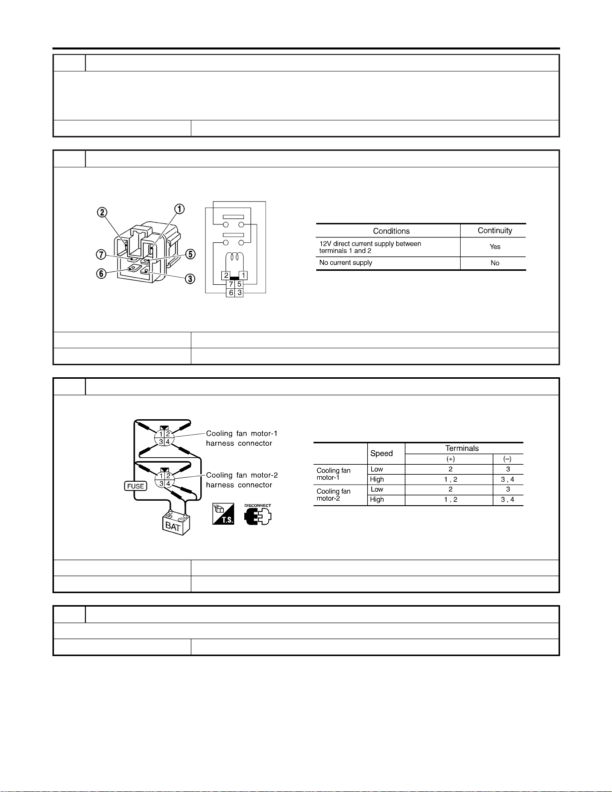
5 DETECT MALFUNCTIONING PART
Check the following.
I Harness connectors E8, E17
I Joint connector-10
I Harness for open or short between cooling fan relays-2 and -3 and ECM
© Repair open circuit or short to ground or short to power in harness or connectors.
6 CHECK COOLING FAN RELAYS-2 AND -3
Check continuity between cooling fan relay-2, -3 terminals 3 and 5, 6 and 7 under the following conditions.
SEF591X
OK or NG
OK © GO TO 7.
NG © Replace cooling fan relays.
7 CHECK COOLING FAN MOTORS
Supply battery voltage between the following terminals and check operation.
SEF592X
OK or NG
OK © GO TO 8.
NG © Replace cooling fan motors.
8 CHECK INTERMITTENT INCIDENT
1. Perform “TROUBLE DIAGNOSIS FOR INTERMITTENT INCIDENT”, EC-156.
© INSPECTION END
DTC P1217 ENGINE OVER TEMPERATURE
Diagnostic Procedure (Cont’d)
EC-548
Main 12 Causes of Overheating
NFEC1327
Engine Step Inspection item Equipment Standard Reference page
OFF 1 I Blocked radiator
I Blocked condenser
I Blocked radiator grille
I Blocked bumper
I Visual No blocking —
2 I Coolant mixture I Coolant tester 50 - 50% coolant mixture See MA-11, “RECOM-
MENDED FLUIDS AND
LUBRICANTS”.
3 I Coolant level I Visual Coolant up to MAX level
in reservoir tank and
radiator filler neck
See MA-14, “Changing
Engine Coolant”.
4 I Radiator cap I Pressure tester 59 - 98 kPa
(0.6 - 1.0 kg/cm
2
,9-14
psi) (Limit)
See LC-12, “System
Check”.
ON*
2
5 I Coolant leaks I Visual No leaks See LC-12, “System
Check”.
ON*
2
6 I Thermostat I Touch the upper and
lower radiator hoses
Both hoses should be
hot
See LC-18, “Thermostat”
and LC-20, “Radiator”.
ON*
1
7 I Cooling fan I CONSULT-II Operating See trouble diagnosis for
DTC P1217 (EC-532).
OFF 8 I Combustion gas leak I Color checker chemi-
cal tester 4 Gas ana-
lyzer
Negative —
ON*
3
9 I Coolant temperature
gauge
I Visual Gauge less than 3/4
when driving
—
I Coolant overflow to
reservoir tank
I Visual No overflow during driv-
ing and idling
See MA-14, “Changing
Engine Coolant”.
OFF*
4
10 I Coolant return from
reservoir tank to radia-
tor
I Visual Should be initial level in
reservoir tank
See MA-13, “ENGINE
MAINTENANCE”.
OFF 11 I Cylinder head I Straight gauge feeler
gauge
0.1 mm (0.004 in) Maxi-
mum distortion (warping)
See EM-42, “Inspection”.
12 I Cylinder block and pis-
tons
I Visual No scuffing on cylinder
walls or piston
See EM-64, “Inspection”.
*1: Turn the ignition switch ON.
*2: Engine running at 3,000 rpm for 10 minutes.
*3: Drive at 90 km/h (55 MPH) for 30 minutes and then let idle for 10 minutes.
*4: After 60 minutes of cool down time.
For more information, refer to LC-25, “OVERHEATING CAUSE ANALYSIS”.
GI
MA
EM
LC
FE
CL
MT
AT
AX
SU
BR
ST
RS
BT
HA
SC
EL
IDX
DTC P1217 ENGINE OVER TEMPERATURE
Main 12 Causes of Overheating
EC-549
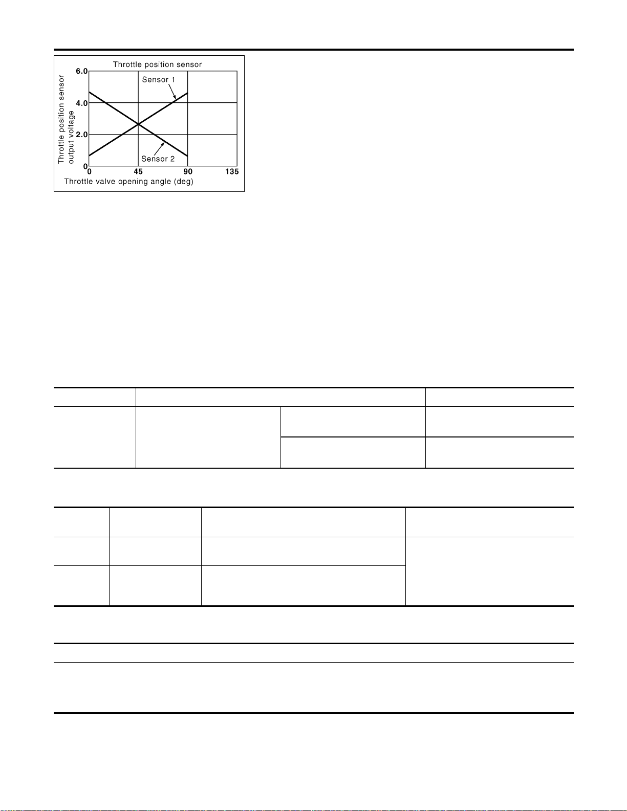
PBIB0145E
Component Description
NFEC1333
Electric Throttle Control Actuator consists of throttle control motor,
throttle position sensor, etc. The throttle position sensor responds
to the throttle valve movement.
The throttle position sensor has the two sensors. These sensors
are a kind of potentiometers which transform the throttle valve
position into output voltage, and emit the voltage signal to the ECM.
In addition, these sensors detect the opening and closing speed of
the throttle valve and feed the voltage signals to the ECM. The
ECM judges the current opening angle of the throttle valve from
these signals and the ECM controls the throttle control motor to
make the throttle valve opening angle properly in response to driv-
ing condition.
CONSULT-II Reference Value in Data Monitor
Mode
NFEC1334
Specification data are reference values.
MONITOR ITEM CONDITION SPECIFICATION
THRTL SEN2
I Ignition switch:
ON (Engine stopped)
I Shift lever:
D (A/T model)
1st (M/T model)
Accelerator pedal: Fully released
More than 0.36V
Accelerator pedal: Fully depressed Less than 4.75V
On Board Diagnosis Logic
NFEC1455
These self-diagnoses have the one trip detection logic.
DTC No.
Trouble diagnosis
name
DTC Detecting Condition Possible Cause
P1223
1223
Throttle position sen-
sor 2 circuit low input
An excessively low voltage from the TP sensor 2
is sent to ECM.
I Harness or connectors
(The TP sensor 2 circuit is open or
shorted.)
I Electric throttle control actuator (TP
sensor 2)
P1224
1224
Throttle position sen-
sor 2 circuit high
input
An excessively high voltage from the TP sensor 2
is sent to ECM.
FAIL-SAFE MODE
NFEC1455S01
When the malfunction is detected, ECM enters in fail-safe mode and the MIL lights up.
Engine operation condition in fail-safe mode
The ECM controls the electric throttle control actuator in regulating the throttle opening in order for the idle position to be within
+10 degrees.
The ECM regulates an opening speed of approx. 5 seconds to an opening of 10 degrees.
So, the acceleration will be poor.
DTC P1223, P1224 TP SENSOR
Component Description
EC-550
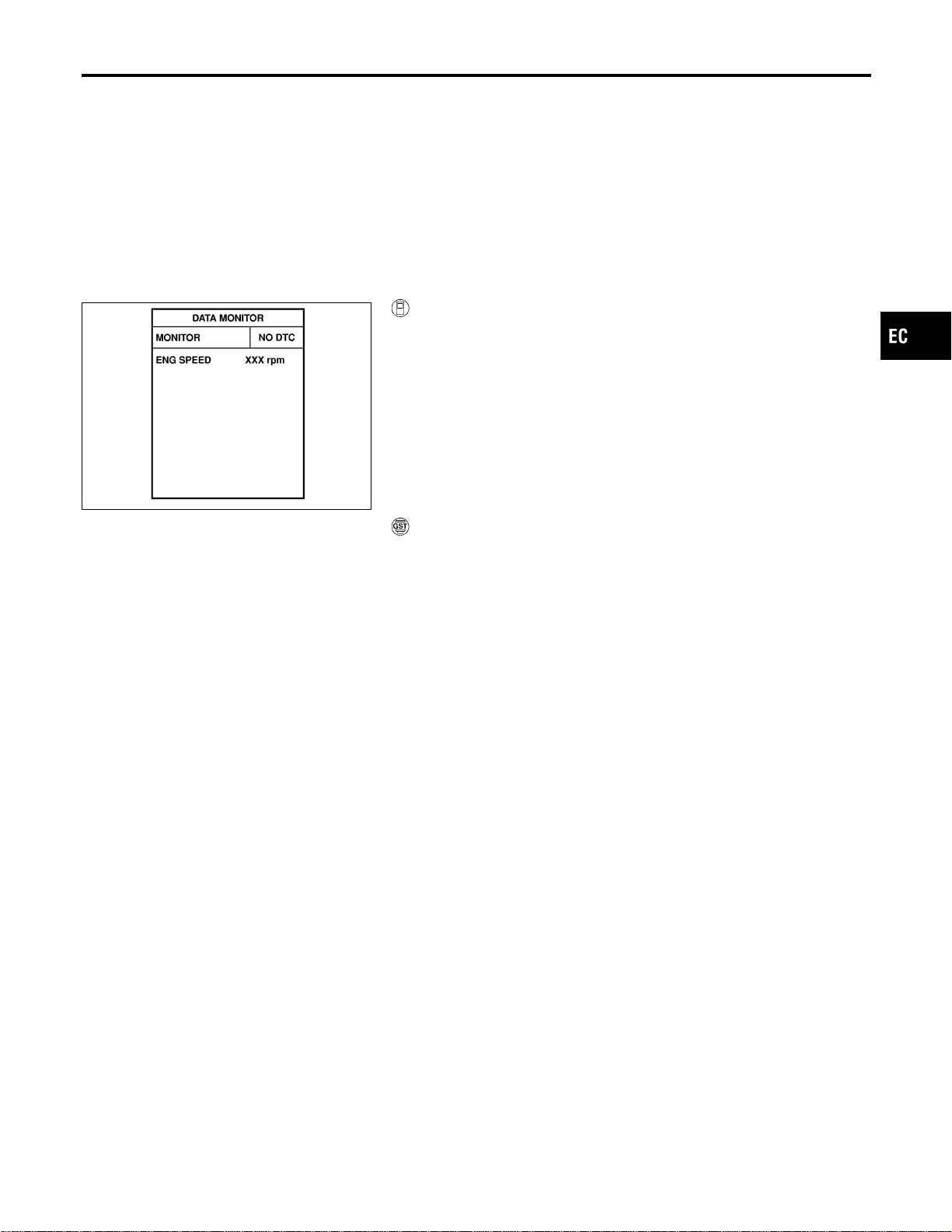
DTC Confirmation Procedure
NFEC1456
NOTE:
If “DTC Confirmation Procedure” has been previously conducted,
always turn ignition switch “OFF” and wait at least 10 seconds
before conducting the next test.
TESTING CONDITION:
Before performing the following procedure, confirm that bat-
tery voltage is more than 10V at idle.
SEF058Y
With CONSULT-II
1) Turn ignition switch “ON”.
2) Select “DATA MONITOR” mode with CONSULT-II.
3) Start engine and let it idle for 1 second.
4) If DTC is detected, go to “Diagnostic Procedure”, EC-553.
With GST
Follow the procedure “With CONSULT-II” above.
GI
MA
EM
LC
FE
CL
MT
AT
AX
SU
BR
ST
RS
BT
HA
SC
EL
IDX
DTC P1223, P1224 TP SENSOR
DTC Confirmation Procedure
EC-551
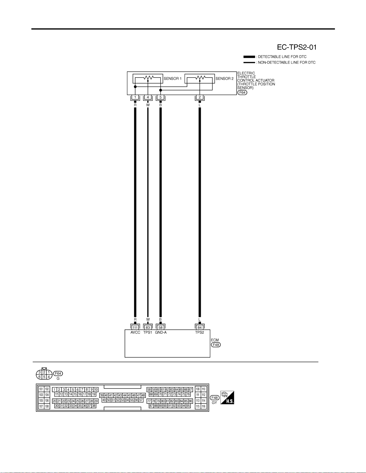
Wiring Diagram
NFEC1337
MEC701D
DTC P1223, P1224 TP SENSOR
Wiring Diagram
EC-552

Specification data are reference values and are measured between each terminal and ground.
CAUTION:
Do not use ECM ground terminals when measuring input/output voltage. Doing so may result in dam-
age to the ECM’s transistor. Use a ground other than ECM terminals, such as the ground.
TERMI-
NAL
NO.
WIRE
COLOR
ITEM CONDITION DATA (DC Voltage)
58 B Sensors’ ground
[Engine is running]
I Warm-up condition
I Idle speed
Approximately 0V
83 W
Throttle position sensor
1
[Ignition switch “ON”]
I Shift lever position is “D” (A/T model)
I Shift lever position is “1st” (M/T model)
I Accelerator pedal fully released
More than 0.36V
[Ignition switch “ON”]
I Shift lever position is “D” (A/T model)
I Shift lever position is “1st” (M/T model)
I Accelerator pedal fully depressed
Less than 4.75V
84 L
Throttle position sensor
2
[Ignition switch “ON”]
I Shift lever position is “D” (A/T model)
I Shift lever position is “1st” (M/T model)
I Accelerator pedal fully released
Less than 4.75V
[Ignition switch “ON”]
I Shift lever position is “D” (A/T model)
I Shift lever position is “1st” (M/T model)
I Accelerator pedal fully depressed
More than 0.36V
111 R Sensor’s power supply [Ignition switch “ON”] Approximately 5V
Diagnostic Procedure
NFEC1338
1 RETIGHTEN GROUND SCREWS
1. Turn ignition switch “OFF”.
2. Loosen and retighten engine ground screws.
SEC047D
© GO TO 2.
GI
MA
EM
LC
FE
CL
MT
AT
AX
SU
BR
ST
RS
BT
HA
SC
EL
IDX
DTC P1223, P1224 TP SENSOR
Wiring Diagram (Cont’d)
EC-553

2 CHECK THROTTLE POSITION SENSOR 2 POWER SUPPLY CIRCUIT
1. Disconnect electric throttle control actuator harness connector.
2. Turn ignition switch “ON”.
SEC054D
3. Check voltage between electric throttle control actuator terminal 1 and ground with CONSULT-II or tester.
PBIB0082E
Voltage: Approximately 5V
OK or NG
OK © GO TO 3.
NG © Repair open circuit or short to ground or short to power in harness or connectors.
3 CHECK THROTTLE POSITION SENSOR 2 GROUND CIRCUIT FOR OPEN AND SHORT
1. Turn ignition switch “OFF”.
2. Check harness continuity between electric throttle control actuator terminal 5 and engine ground.
Refer to Wiring Diagram.
Continuity should exist.
3. Also check harness for short to ground and short to power.
OK or NG
OK © GO TO 5.
NG © GO TO 4.
4 DETECT MALFUNCTIONING PART
Check the following.
I Harness for open or short between electric throttle control actuator and ECM
© Repair open circuit or short to ground or short to power in harness or connectors.
DTC P1223, P1224 TP SENSOR
Diagnostic Procedure (Cont’d)
EC-554
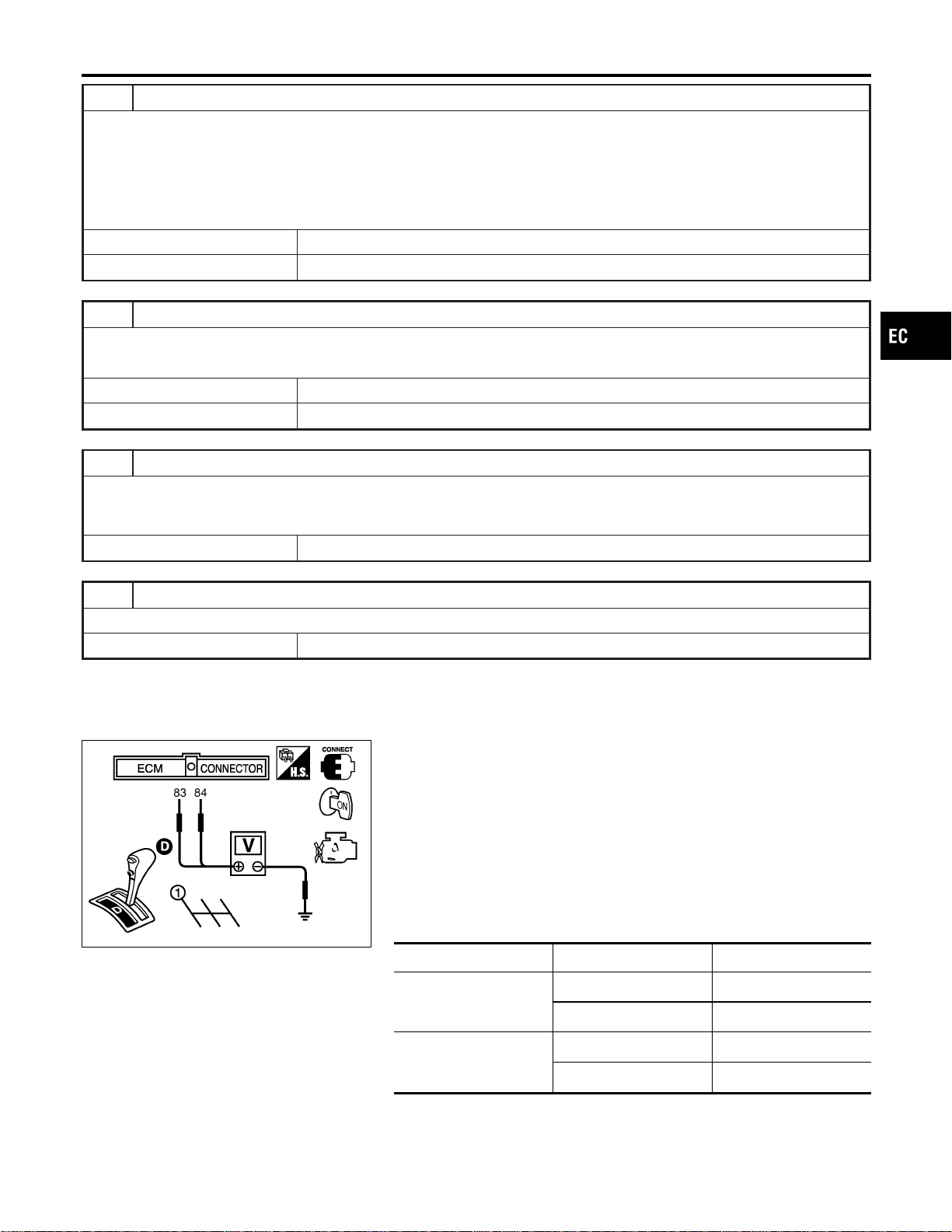
5 CHECK THROTTLE POSITION SENSOR 2 INPUT SIGNAL CIRCUIT FOR OPEN AND SHORT
1. Disconnect ECM harness connector.
2. Check harness continuity between ECM terminal 84 and electric throttle control actuator terminal 2.
Refer to Wiring Diagram.
Continuity should exist.
3. Also check harness for short to ground and short to power.
OK or NG
OK © GO TO 6.
NG © Repair open circuit or short to ground or short to power in harness or connectors.
6 CHECK THROTTLE POSITION SENSOR
Refer to “Component Inspection”, EC-555.
OK or NG
OK © GO TO 8.
NG © GO TO 7.
7 REPLACE ELECTRIC THROTTLE CONTROL ACTUATOR
1. Replace the electric throttle control actuator.
2. Perform “Throttle Valve Closed Position Learning”, EC-71.
3. Perform “Idle Air Volume Learning”, EC-71.
© INSPECTION END
8 CHECK INTERMITTENT INCIDENT
Refer to “TROUBLE DIAGNOSIS FOR INTERMITTENT INCIDENT”, EC-156.
© INSPECTION END
SEC900C
Component Inspection
NFEC1339
THROTTLE POSITION SENSOR
1. Reconnect all harness connectors disconnected.
2. Perform “Throttle Valve Closed Position Learning”, EC-71.
3. Turn ignition switch “ON”.
4. Set selector lever to “D” position (A/T models) or “1st” position
(M/T models).
5. Check voltage between ECM terminals 83 (TP sensor 1), 84
(TP sensor 2) and engine ground under the following condi-
tions.
Terminal Accelerator pedal Voltage
83
(Throttle position sensor
1)
Fully released More than 0.36V
Fully depressed Less than 4.75V
84
(Throttle position sensor
2)
Fully released Less than 4.75V
Fully depressed More than 0.36V
6. If NG, replace electric throttle control actuator and go to the
next step.
7. Perform “Throttle Valve Closed Position Learning”, EC-71.
GI
MA
EM
LC
FE
CL
MT
AT
AX
SU
BR
ST
RS
BT
HA
SC
EL
IDX
DTC P1223, P1224 TP SENSOR
Diagnostic Procedure (Cont’d)
EC-555

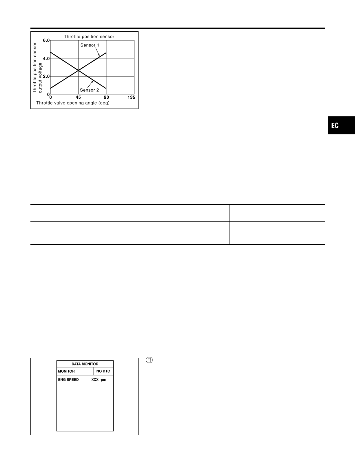
PBIB0145E
Component Description
NFEC1340
Electric Throttle Control Actuator consists of throttle control motor,
throttle position sensor, etc. The throttle position sensor responds
to the throttle valve movement.
The throttle position sensor has the two sensors. These sensors
are a kind of potentiometers which transform the throttle valve
position into output voltage, and emit the voltage signal to the ECM.
In addition, these sensors detect the opening and closing speed of
the throttle valve and feed the voltage signals to the ECM. The
ECM judges the current opening angle of the throttle valve from
these signals and the ECM controls the throttle control motor to
make the throttle valve opening angle properly in response to driv-
ing condition.
On Board Diagnosis Logic
NFEC1342
DTC No.
Trouble diagnosis
name
DTC Detecting Condition Possible Cause
P1225
1225
Closed throttle posi-
tion learning perfor-
mance problem
Closed throttle position learning value is exces-
sively low.
I Electric throttle control actuator (TP
sensor 1 and 2)
DTC Confirmation Procedure
NFEC1343
NOTE:
If “DTC Confirmation Procedure” has been previously conducted,
always turn ignition switch “OFF” and wait at least 10 seconds
before conducting the next test.
TESTING CONDITION:
Before performing the following procedure, confirm that bat-
tery voltage is more than 10V at idle.
SEF058Y
With CONSULT-II
1) Turn ignition switch “ON”.
2) Select “DATA MONITOR” mode with CONSULT-II.
3) Turn ignition switch “OFF”, wait at least 10 seconds.
4) Turn ignition switch “ON”.
5) If 1st trip DTC is detected, go to “Diagnostic Procedure”,
EC-558.
GI
MA
EM
LC
FE
CL
MT
AT
AX
SU
BR
ST
RS
BT
HA
SC
EL
IDX
DTC P1225 TP SENSOR
Component Description
EC-557
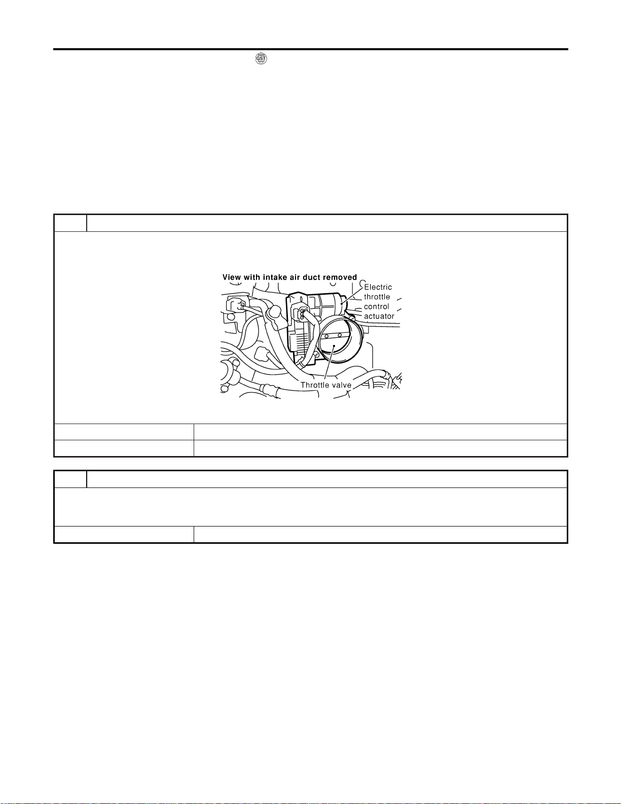
With GST
Follow the procedure “With CONSULT-II” above.m
Diagnostic Procedure
NFEC1345
1 CHECK ELECTRIC THROTTLE CONTROL ACTUATOR VISUALLY
1. Turn ignition switch “OFF”.
2. Remove the intake air duct.
3. Check if foreign matter is caught between the throttle valve and the housing.
SEC083D
OK or NG
OK © GO TO 2.
NG © Remove the foreign matter and clean the electric throttle control actuator inside.
2 REPLACE ELECTRIC THROTTLE CONTROL ACTUATOR
1. Replace the electric throttle control actuator.
2. Perform “Throttle Valve Closed Position Learning”, EC-71.
3. Perform “Idle Air Volume Learning”, EC-71.
© INSPECTION END
DTC P1225 TP SENSOR
DTC Confirmation Procedure (Cont’d)
EC-558
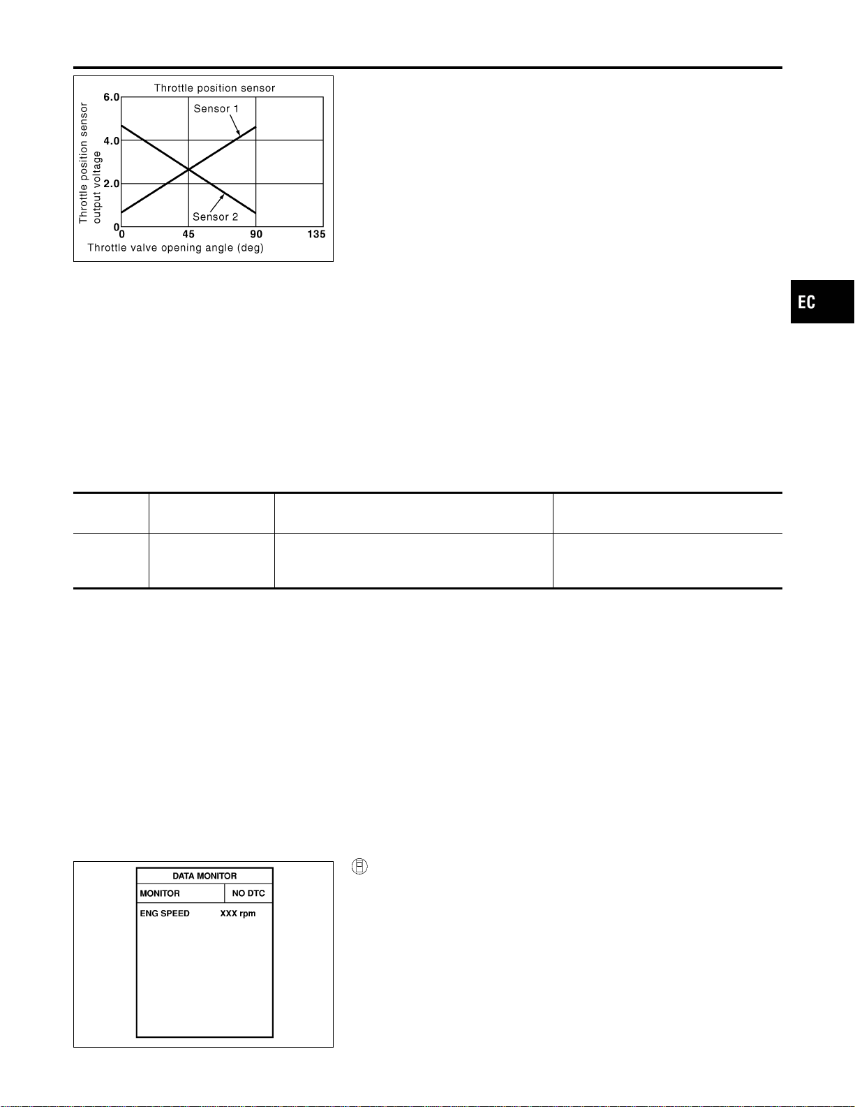
PBIB0145E
Component Description
NFEC1361
Electric Throttle Control Actuator consists of throttle control motor,
throttle position sensor, etc. The throttle position sensor responds
to the throttle valve movement.
The throttle position sensor has the two sensors. These sensors
are a kind of potentiometers which transform the throttle valve
position into output voltage, and emit the voltage signal to the ECM.
In addition, these sensors detect the opening and closing speed of
the throttle valve and feed the voltage signals to the ECM. The
ECM judges the current opening angle of the throttle valve from
these signals and the ECM controls the throttle control motor to
make the throttle valve opening angle properly in response to driv-
ing condition.
On Board Diagnosis Logic
NFEC1362
DTC No.
Trouble diagnosis
name
DTC Detecting Condition Possible Cause
P1226
1226
Closed throttle posi-
tion learning perfor-
mance problem
Closed throttle position learning is not performed
successfully, repeatedly.
I Electric throttle control actuator (TP
sensor 1 and 2)
DTC Confirmation Procedure
NFEC1363
NOTE:
If “DTC Confirmation Procedure” has been previously conducted,
always turn ignition switch “OFF” and wait at least 10 seconds
before conducting the next test.
TESTING CONDITION:
Before performing the following procedure, confirm that bat-
tery voltage is more than 10V at idle.
SEF058Y
With CONSULT-II
1) Turn ignition switch “ON”.
2) Select “DATA MONITOR” mode with CONSULT-II.
3) Turn ignition switch “OFF”, wait at least 10 seconds.
4) Turn ignition switch “ON”.
5) Repeat steps 3 and 4, 32 times.
6) If 1st trip DTC is detected, go to “Diagnostic Procedure”,
EC-560.
GI
MA
EM
LC
FE
CL
MT
AT
AX
SU
BR
ST
RS
BT
HA
SC
EL
IDX
DTC P1226 TP SENSOR
Component Description
EC-559
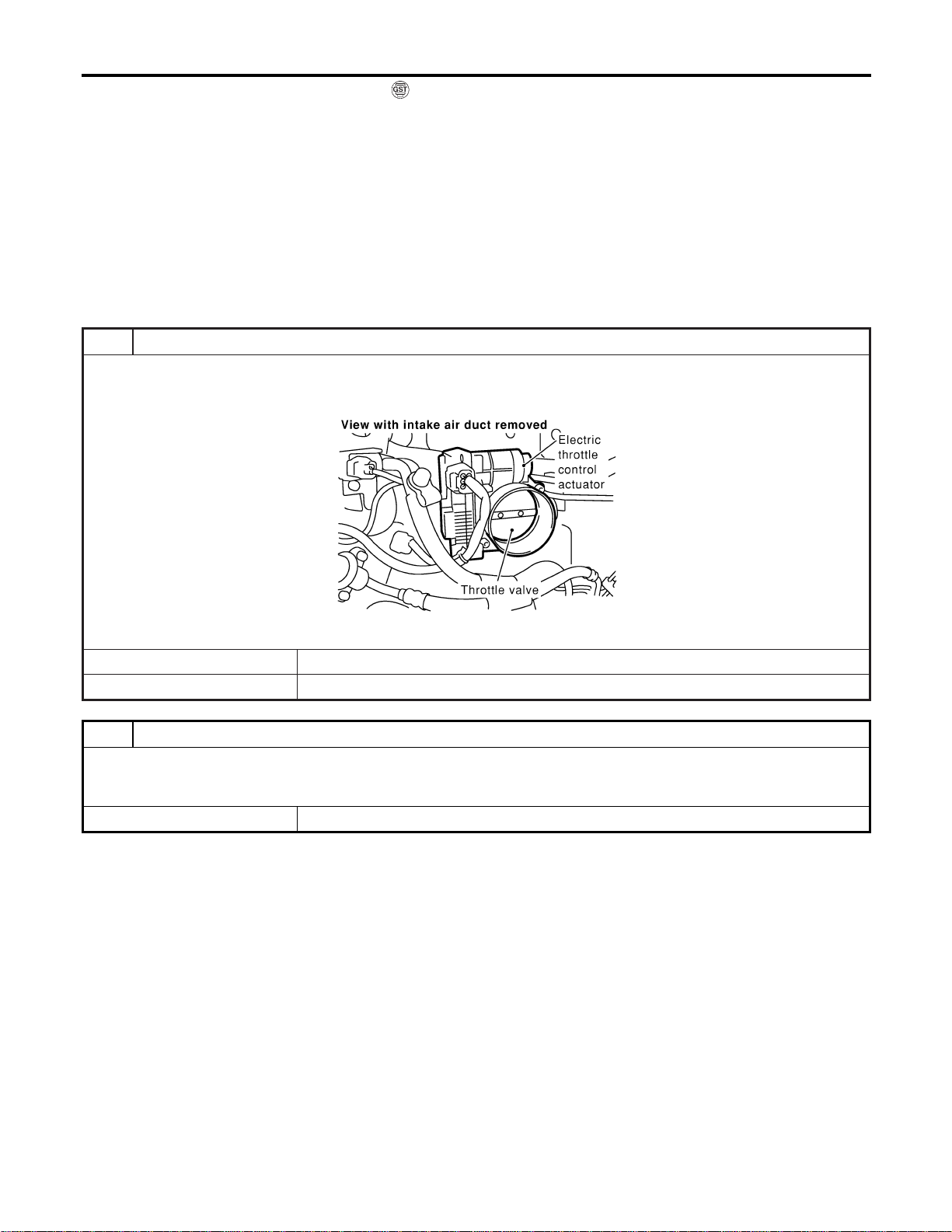
With GST
Follow the procedure “With CONSULT-II” above.
Diagnostic Procedure
NFEC1364
1 CHECK ELECTRIC THROTTLE CONTROL ACTUATOR VISUALLY
1. Turn ignition switch “OFF”.
2. Remove the intake air duct.
3. Check if foreign matter is caught between the throttle valve and the housing.
SEC083D
OK or NG
OK © GO TO 2.
NG © Remove the foreign matter and clean the electric throttle control actuator inside.
2 REPLACE ELECTRIC THROTTLE CONTROL ACTUATOR
1. Replace the electric throttle control actuator.
2. Perform “Throttle Valve Closed Position Learning”, EC-71.
3. Perform “Idle Air Volume Learning”, EC-71.
© INSPECTION END
DTC P1226 TP SENSOR
DTC Confirmation Procedure (Cont’d)
EC-560
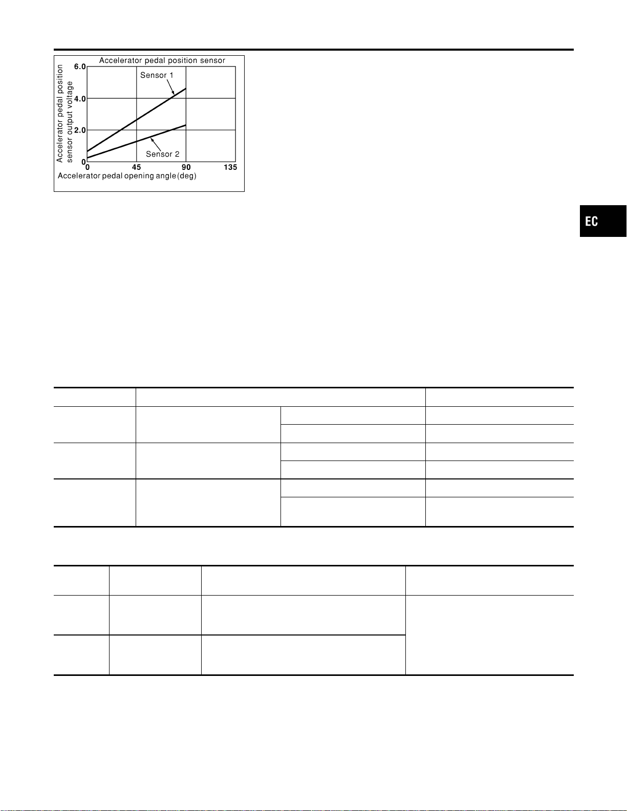
PBIB0146E
Component Description
NFEC1347
The accelerator pedal position sensor is installed on the upper end
of the accelerator pedal assembly. The sensor detects the accel-
erator position and sends a signal to the ECM.
Accelerator pedal position sensor has two sensors. These sensors
are a kind of potentiometers which transform the accelerator pedal
position into output voltage, and emit the voltage signal to the ECM.
In addition, these sensors detect the opening and closing speed of
the accelerator pedal and feed the voltage signals to the ECM. The
ECM judges the current opening angle of the accelerator pedal
from these signals and controls the throttle control motor based on
these signals.
Idle position of the accelerator pedal is determined by the ECM
receiving the signal from the accelerator pedal position sensor. The
ECM uses this signal for the engine operation such as fuel cut.
CONSULT-II Reference Value in Data Monitor
Mode
NFEC1348
Specification data are reference values.
MONITOR ITEM CONDITION SPECIFICATION
ACCEL SEN1
I Ignition switch: ON (engine
stopped)
Accelerator pedal: Fully released 0.41 - 0.71V
Accelerator pedal: Fully depressed More than 3.7V
ACCEL SEN2
I Ignition switch: ON (engine
stopped)
Accelerator pedal: Fully released 0.15 - 0.97V
Accelerator pedal: Fully depressed More than 3.5V
CLSD THL POS I Ignition switch: ON
Accelerator pedal: Fully released ON
Accelerator pedal: Slightly
depressed
OFF
On Board Diagnosis Logic
NFEC1457
These self-diagnoses have the one trip detection logic.
DTC No.
Trouble diagnosis
name
DTC Detecting Condition Possible Cause
P1227
1227
Accelerator pedal
position sensor 2 cir-
cuit low input
An excessively low voltage from the APP sensor 2
is sent to ECM.
I Harness or connectors
(The APP sensor 2 circuit is open or
shorted.)
I Accelerator pedal position sensor
(Accelerator pedal position sensor 2)
P1228
1228
Accelerator pedal
position sensor 2 cir-
cuit high input
An excessively high voltage from the APP sensor
2 is sent to ECM.
GI
MA
EM
LC
FE
CL
MT
AT
AX
SU
BR
ST
RS
BT
HA
SC
EL
IDX
DTC P1227, P1228 APP SENSOR
Component Description
EC-561
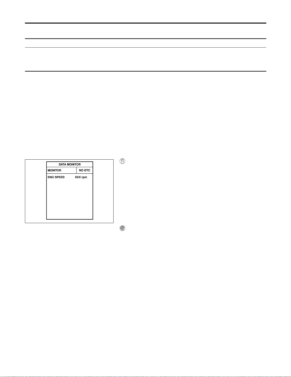
FAIL-SAFE MODE
=NFEC1457S01
When the malfunction is detected, ECM enters in fail-safe mode and the MIL lights up.
Engine operating condition in fail-safe mode
The ECM controls the electric throttle control actuator in regulating the throttle opening in order for the idle position to be within
+10 degrees.
The ECM regulates an opening speed of approx. 5 seconds to an opening of 10 degrees.
So, the acceleration will be poor.
DTC Confirmation Procedure
NFEC1458
NOTE:
If “DTC Confirmation Procedure” has been previously conducted,
always turn ignition switch “OFF” and wait at least 10 seconds
before conducting the next test.
TESTING CONDITION:
Before performing the following procedure, confirm that bat-
tery voltage is more than 10V at idle.
SEF058Y
With CONSULT-II
1) Turn ignition switch “ON”.
2) Select “DATA MONITOR” mode with CONSULT-II.
3) Start engine and let it idle for 1 second.
4) If DTC is detected, go to “Diagnostic Procedure”, EC-564.
With GST
Follow the procedure “With CONSULT-II” above.
DTC P1227, P1228 APP SENSOR
On Board Diagnosis Logic (Cont’d)
EC-562
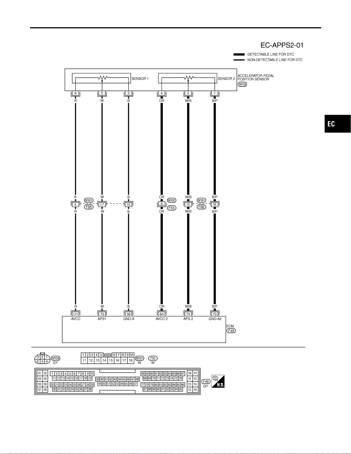
Wiring Diagram
NFEC1351
MEC927D
GI
MA
EM
LC
FE
CL
MT
AT
AX
SU
BR
ST
RS
BT
HA
SC
EL
IDX
DTC P1227, P1228 APP SENSOR
Wiring Diagram
EC-563
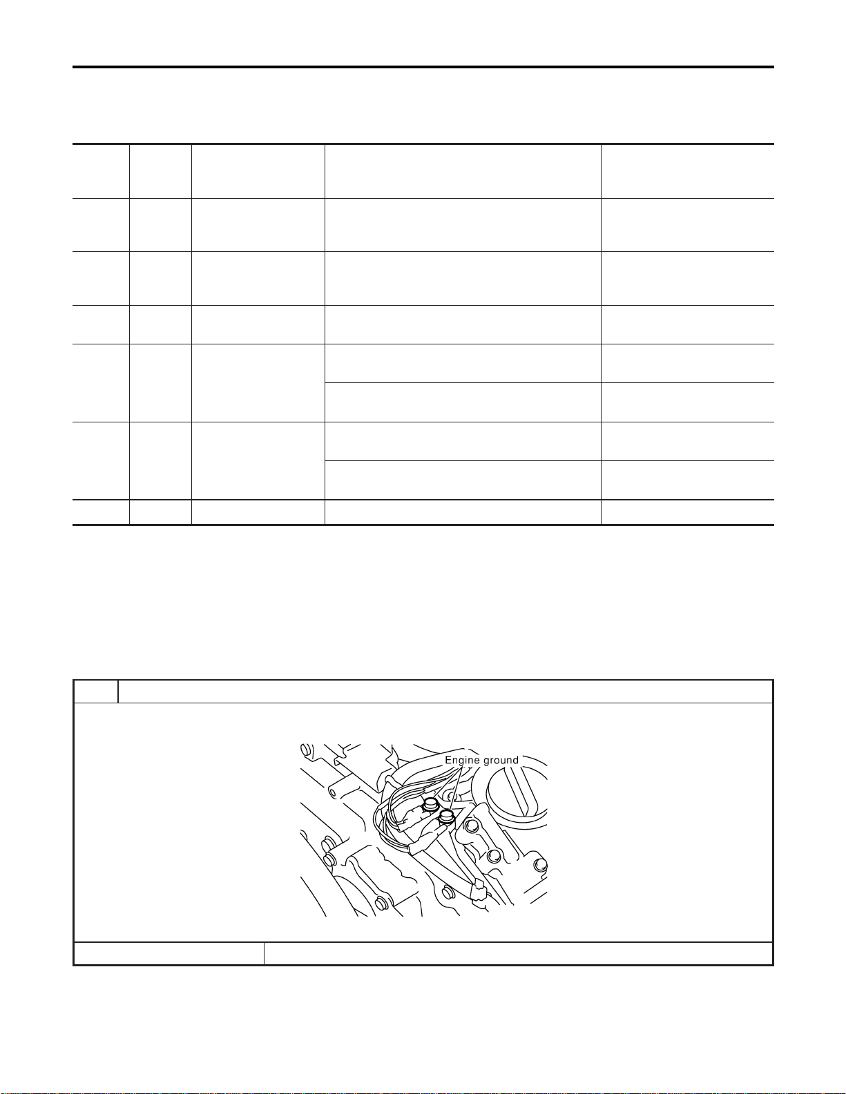
Specification data are reference values and are measured between each terminal and ground.
CAUTION:
Do not use ECM ground terminals when measuring input/output voltage. Doing so may result in dam-
age to the ECM’s transistor. Use a ground other than ECM terminals, such as the ground.
TERMI-
NAL
NO.
WIRE
COLOR
ITEM CONDITION DATA (DC Voltage)
58 B Sensors’ ground
[Engine is running]
I Warm-up condition
I Idle speed
Approximately 0V
64 OR
Accelerator pedal posi-
tion sensor 2 power
supply
[Ignition switch “ON”] Approximately 2.5V
70 B/P
Accelerator pedal posi-
tion sensor 2 ground
[Ignition switch “ON”] Approximately 0V
73 W
Accelerator pedal posi-
tion sensor 1
[Ignition switch “ON”]
I Accelerator pedal fully released
0.41 - 0.71V
[Ignition switch “ON”]
I Accelerator pedal fully depressed
More than 3.7V
74 W/B
Accelerator pedal posi-
tion sensor 2
[Ignition switch “ON”]
I Accelerator pedal fully released
0.08 - 0.48V
[Ignition switch “ON”]
I Accelerator pedal fully depressed
More than 1.8V
111 R Sensor’s power supply [Ignition switch “ON”] Approximately 5V
Diagnostic Procedure
NFEC1352
1 RETIGHTEN GROUND SCREWS
1. Turn ignition switch “OFF”.
2. Loosen and retighten engine ground screws.
SEC047D
© GO TO 2.
DTC P1227, P1228 APP SENSOR
Wiring Diagram (Cont’d)
EC-564
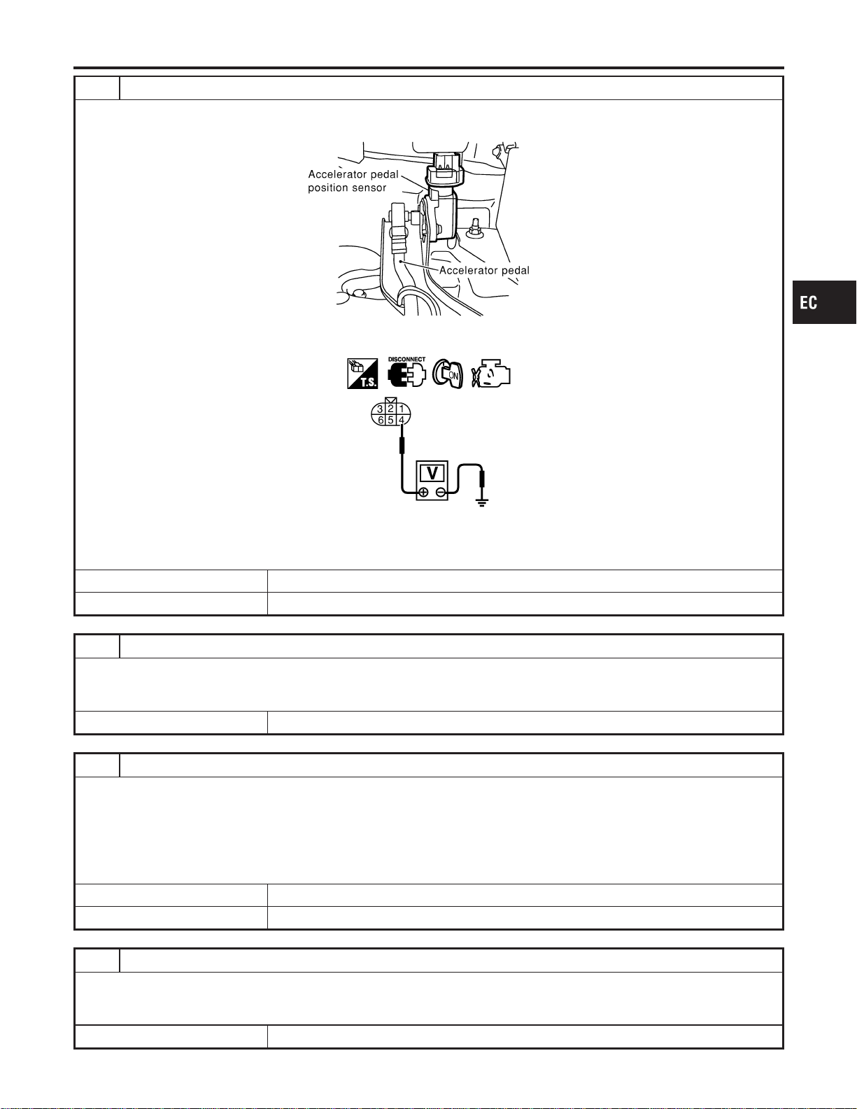
2 CHECK APP SENSOR 2 POWER SUPPLY CIRCUIT
1. Disconnect accelerator pedal position (APP) sensor harness connector.
2. Turn ignition switch “ON”.
SEC081D
3. Check voltage between APP sensor terminal 4 and ground with CONSULT-II or tester.
SEC094D
Voltage: Approximately 2.5V
OK or NG
OK © GO TO 4.
NG © GO TO 3.
3 DETECT MALFUNCTIONING PART
Check the following.
I Harness connectors M162, F55
I Harness for open or short between ECM and accelerator pedal position sensor
© Repair open circuit or short to ground or short to power in harness or connectors.
4 CHECK APP SENSOR 2 GROUND CIRCUIT FOR OPEN AND SHORT
1. Turn ignition switch “OFF”.
2. Check harness continuity between APP sensor terminal 1 and engine ground.
Refer to Wiring Diagram.
Continuity should exist.
3. Also check harness for short to ground and short to power.
OK or NG
OK © GO TO 6.
NG © GO TO 5.
5 DETECT MALFUNCTIONING PART
Check the following.
I Harness connectors M161, F68
I Harness for open or short between ECM and accelerator pedal position sensor
© Repair open circuit or short to ground or short to power in harness or connectors.
GI
MA
EM
LC
FE
CL
MT
AT
AX
SU
BR
ST
RS
BT
HA
SC
EL
IDX
DTC P1227, P1228 APP SENSOR
Diagnostic Procedure (Cont’d)
EC-565
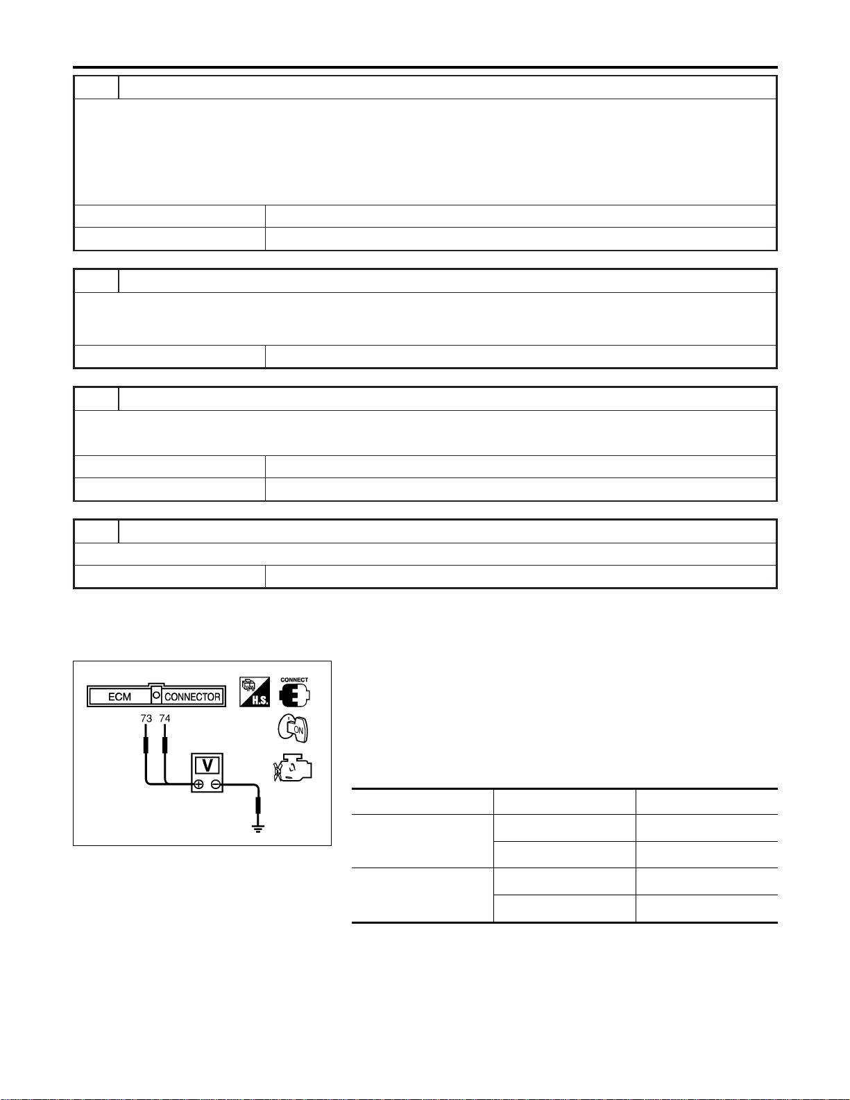
6 CHECK APP SENSOR 2 INPUT SIGNAL CIRCUIT FOR OPEN AND SHORT
1. Disconnect ECM harness connector.
2. Check harness continuity between ECM terminal 74 and APP sensor terminal 2.
Refer to Wiring Diagram.
Continuity should exist.
3. Also check harness for short to ground and short to power.
OK or NG
OK © GO TO 8.
NG © GO TO 7.
7 DETECT MALFUNCTIONING PART
Check the following.
I Harness connectors M161, F68
I Harness for open or short between ECM and accelerator pedal position sensor
© Repair open circuit or short to ground or short to power in harness or connectors.
8 CHECK APP SENSOR
Refer to “Component Inspection”, EC-566.
OK or NG
OK © GO TO 9.
NG © Replace accelerator pedal assembly.
9 CHECK INTERMITTENT INCIDENT
Refer to “TROUBLE DIAGNOSIS FOR INTERMITTENT INCIDENT”, EC-156.
© INSPECTION END
SEC901C
Component Inspection
NFEC1459
ACCELERATOR PEDAL POSITION SENSOR
1. Reconnect all harness connectors disconnected.
2. Turn ignition switch “ON”.
3. Check voltage between ECM terminals 73 (APP sensor 1
signal), 74 (APP sensor 2 signal) and engine ground under the
following conditions.
Terminal Accelerator pedal Voltage
73
(Accelerator pedal posi-
tion sensor 1)
Fully released 0.41 - 0.71V
Fully depressed More than 3.7V
74
(Accelerator pedal posi-
tion sensor 2)
Fully released 0.08 - 0.48V
Fully depressed More than 1.8V
4. If NG, replace accelerator pedal assembly.
5. Perform “Accelerator Pedal Released Position Learning”,
EC-71.
6. Perform “Throttle Valve Closed Position Learning”, EC-71.
7. Perform “Idle Air Volume Learning”, EC-71.
DTC P1227, P1228 APP SENSOR
Diagnostic Procedure (Cont’d)
EC-566
On Board Diagnosis Logic
NFEC1460
This self-diagnosis has the one trip detection logic.
DTC No.
Trouble diagnosis
name
DTC Detecting Condition Possible Cause
P1229
1229
Sensor power supply
circuit short
ECM detects a voltage of power source for sensor
is excessively low or high.
I Harness or connectors
(The TP sensor 1 and 2 circuit is
shorted.)
(APP sensor circuit is shorted.)
(MAF sensor circuit is shorted.)
(EVAP control system pressure sen-
sor circuit is shorted.)
(Power steering pressure sensor cir-
cuit is shorted.)
(Refrigerant pressure sensor circuit is
shorted.)
I Electric throttle control actuator
(TP sensor 1 and 2)
I Accelerator pedal position sensor
(APP sensor 1)
I MAF sensor
I EVAP control system pressure sensor
I Power steering pressure sensor
I Refrigerant pressure sensor
I ECM pin terminal
FAIL-SAFE MODE
NFEC1460S01
When the malfunction is detected, ECM enters in fail-safe mode and the MIL lights up.
Engine operation condition in fail-safe mode
ECM stops the electric throttle control actuator control, throttle valve is maintained at a fixed opening (approx. 5 degrees) by the
return spring.
DTC Confirmation Procedure
NFEC1461
NOTE:
If “DTC Confirmation Procedure” has been previously conducted,
always turn ignition switch “OFF” and wait at least 10 seconds
before conducting the next test.
TESTING CONDITION:
Before performing the following procedure, confirm that bat-
tery voltage is more than 10V at idle.
SEF058Y
With CONSULT-II
1) Turn ignition switch “ON”.
2) Select “DATA MONITOR” mode with CONSULT-II.
3) Start engine and let it idle for 1 second.
4) If DTC is detected, go to “Diagnostic Procedure”, EC-570.
GI
MA
EM
LC
FE
CL
MT
AT
AX
SU
BR
ST
RS
BT
HA
SC
EL
IDX
DTC P1229 SENSOR POWER SUPPLY
On Board Diagnosis Logic
EC-567

With GST
Follow the procedure “With CONSULT-II” above.
DTC P1229 SENSOR POWER SUPPLY
DTC Confirmation Procedure (Cont’d)
EC-568
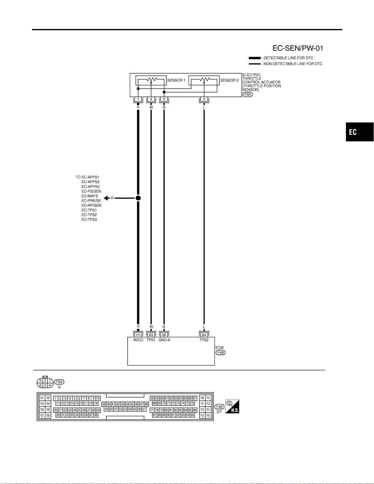
Wiring Diagram
NFEC1358
MEC657D
GI
MA
EM
LC
FE
CL
MT
AT
AX
SU
BR
ST
RS
BT
HA
SC
EL
IDX
DTC P1229 SENSOR POWER SUPPLY
Wiring Diagram
EC-569
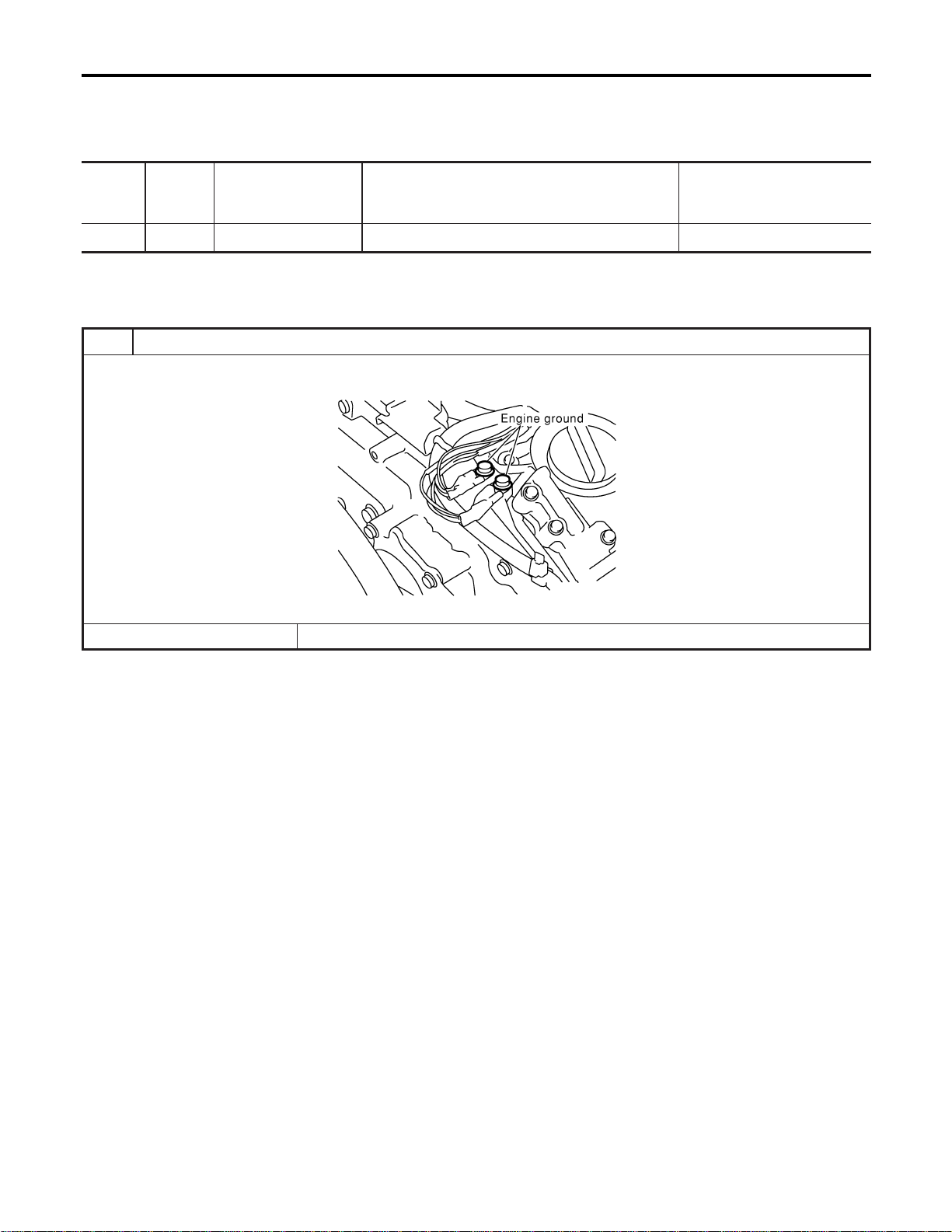
Specification data are reference values and are measured between each terminal and ground.
CAUTION:
Do not use ECM ground terminals when measuring input/output voltage. Doing so may result in dam-
age to the ECM’s transistor. Use a ground other than ECM terminals, such as the ground.
TERMI-
NAL
NO.
WIRE
COLOR
ITEM CONDITION DATA (DC Voltage)
111 R Sensor’s power supply [Ignition switch “ON”] Approximately 5V
Diagnostic Procedure
NFEC1359
1 RETIGHTEN GROUND SCREWS
1. Turn ignition switch “OFF”.
2. Loosen and retighten engine ground screws.
SEC047D
© GO TO 2.
DTC P1229 SENSOR POWER SUPPLY
Wiring Diagram (Cont’d)
EC-570
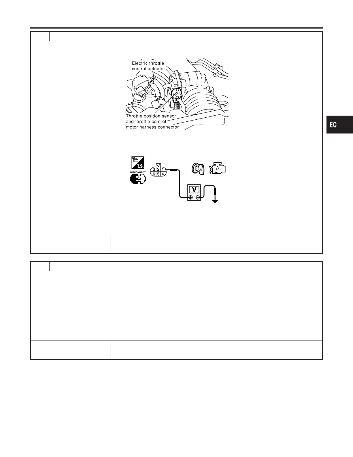
2 CHECK THROTTLE POSITION SENSOR POWER SUPPLY CIRCUIT
1. Disconnect electric throttle control actuator harness connector.
2. Turn ignition switch “ON”.
SEC054D
3. Check voltage between electric throttle control actuator terminal 1 and ground with CONSULT-II or tester.
PBIB0082E
Voltage: Approximately 5V
OK or NG
OK © GO TO 5.
NG © GO TO 3.
3 CHECK SENSOR POWER SUPPLY CIRCUITS
Check the following.
I Harness for short to power and short to ground, between the following terminals.
ECM terminal 111 and electric throttle control actuator terminal 1. Refer to “Wiring Diagram”, EC-569.
ECM terminal 111 and APP sensor terminal 2. Refer to “Wiring Diagram”, EC-313.
ECM terminal 111 and MAF sensor terminal 2. Refer to “Wiring Diagram”, EC-197.
ECM terminal 111 and EVAP control system pressure sensor terminal 1. Refer to “Wiring Diagram”, EC-392.
ECM terminal 111 and power steering pressure sensor terminal 1. Refer to “Wiring Diagram”, EC-451.
ECM terminal 111 and refrigerant pressure sensor terminal 1. Refer to “Wiring Diagram”, EC-725.
I ECM pin terminal
OK or NG
OK © GO TO 4.
NG © Repair short to ground or short to power in harness or connectors.
GI
MA
EM
LC
FE
CL
MT
AT
AX
SU
BR
ST
RS
BT
HA
SC
EL
IDX
DTC P1229 SENSOR POWER SUPPLY
Diagnostic Procedure (Cont’d)
EC-571
4 CHECK COMPONENTS
Check the following.
I Accelerator pedal position sensor (Refer to “Component Inspection”, EC-309.)
I Mass air flow sensor (Refer to “Diagnostic Procedure”, EC-192.)
I EVAP control system pressure sensor (Refer to “Diagnostic Procedure”, EC-393.)
I Power steering pressure sensor (Refer to “Component Inspection”, EC-454.)
I Refrigerant pressure sensor (Refer to “Diagnostic Procedure”, EC-726.)
OK or NG
OK © GO TO 7.
NG © Replace malfunctioning component.
5 CHECK THROTTLE POSITION SENSOR
Refer to “Component Inspection”, EC-295.
OK or NG
OK © GO TO 7.
NG © GO TO 6.
6 REPLACE ELECTRIC THROTTLE CONTROL ACTUATOR
1. Replace electric throttle control actuator.
2. Perform “Throttle valve closed position learning”, EC-71.
3. Perform “Idle air volume learning”, EC-71.
© INSPECTION END
7 CHECK INTERMITTENT INCIDENT
Refer to “TROUBLE DIAGNOSIS FOR INTERMITTENT INCIDENT”, EC-156.
© INSPECTION END
DTC P1229 SENSOR POWER SUPPLY
Diagnostic Procedure (Cont’d)
EC-572
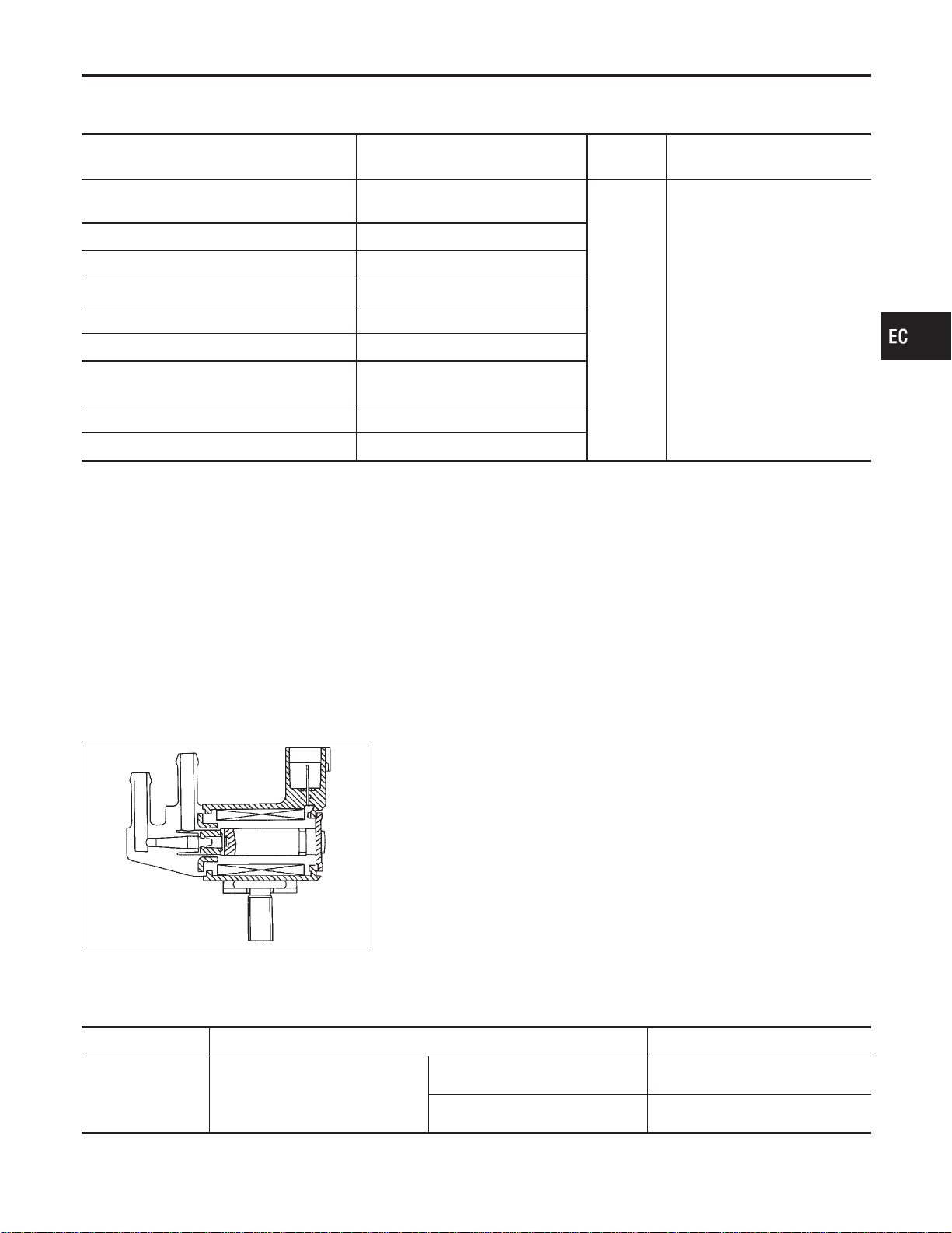
Description
NFEC1089
SYSTEM DESCRIPTION
NFEC1089S01
Sensor Input Signal to ECM
ECM
function
Actuator
Crankshaft position sensor (POS)
Camshaft position sensor (PHASE)
Engine speed
EVAP can-
ister purge
flow control
EVAP canister purge volume
control solenoid valve
Mass air flow sensor Amount of intake air
Engine coolant temperature sensor Engine coolant temperature
Ignition switch Start signal
Throttle position sensor Throttle position
Accelerator pedal position sensor Accelerator pedal position
Heated oxygen sensor 1
Density of oxygen in exhaust gas
(Mixture ratio feedback signal)
Fuel tank temperature sensor Fuel temperature in fuel tank
Vehicle speed sensor Vehicle speed
This system controls flow rate of fuel vapor from the EVAP canis-
ter. The opening of the vapor by-pass passage in the EVAP canis-
ter purge volume control solenoid valve changes to control the flow
rate. The EVAP canister purge volume control solenoid valve
repeats ON/OFF operation according to the signal sent from the
ECM. The opening of the valve varies for optimum engine control.
The optimum value stored in the ECM is determined by consider-
ing various engine conditions. When the engine is operating, the
flow rate of fuel vapor from the EVAP canister is regulated as the
air flow changes.
SEF337U
COMPONENT DESCRIPTION
NFEC1089S02
The EVAP canister purge volume control solenoid valve uses a
ON/OFF duty to control the flow rate of fuel vapor from the EVAP
canister. The EVAP canister purge volume control solenoid valve
is moved by ON/OFF pulses from the ECM. The longer the ON
pulse, the greater the amount of fuel vapor that will flow through the
valve.
CONSULT-II Reference Value in Data Monitor
Mode
NFEC1090
Specification data are reference values.
MONITOR ITEM CONDITION SPECIFICATION
PURG VOL C/V
I Engine: After warming up
I Air conditioner switch “OFF”
I Shift lever: “N”
I No-load
Idle (Vehicle stopped) 0%
2,000 rpm —
GI
MA
EM
LC
FE
CL
MT
AT
AX
SU
BR
ST
RS
BT
HA
SC
EL
IDX
DTC P1444 EVAP CANISTER PURGE VOLUME CONTROL SOLENOID VALVE
Description
EC-573

On Board Diagnosis Logic
NFEC1092
DTC No.
Trouble diagnosis
name
DTC Detecting Condition Possible Cause
P1444
1444
EVAP canister purge
volume control sole-
noid valve
The canister purge flow is detected during the
specified driving conditions, even when EVAP can-
ister purge volume control solenoid valve is com-
pletely closed.
I EVAP control system pressure sensor
I EVAP canister purge volume control
solenoid valve (The valve is stuck
open.)
I EVAP canister vent control valve
I EVAP canister
I Hoses
(Hoses are connected incorrectly or
clogged.)
DTC Confirmation Procedure
NFEC1093
NOTE:
If “DTC Confirmation Procedure” has been previously conducted,
always turn ignition switch “OFF” and wait at least 10 seconds
before conducting the next test.
TESTING CONDITION:
Always perform test at a temperature of 5°C (41°F) or more.
DTC P1444 EVAP CANISTER PURGE VOLUME CONTROL SOLENOID VALVE
On Board Diagnosis Logic
EC-574
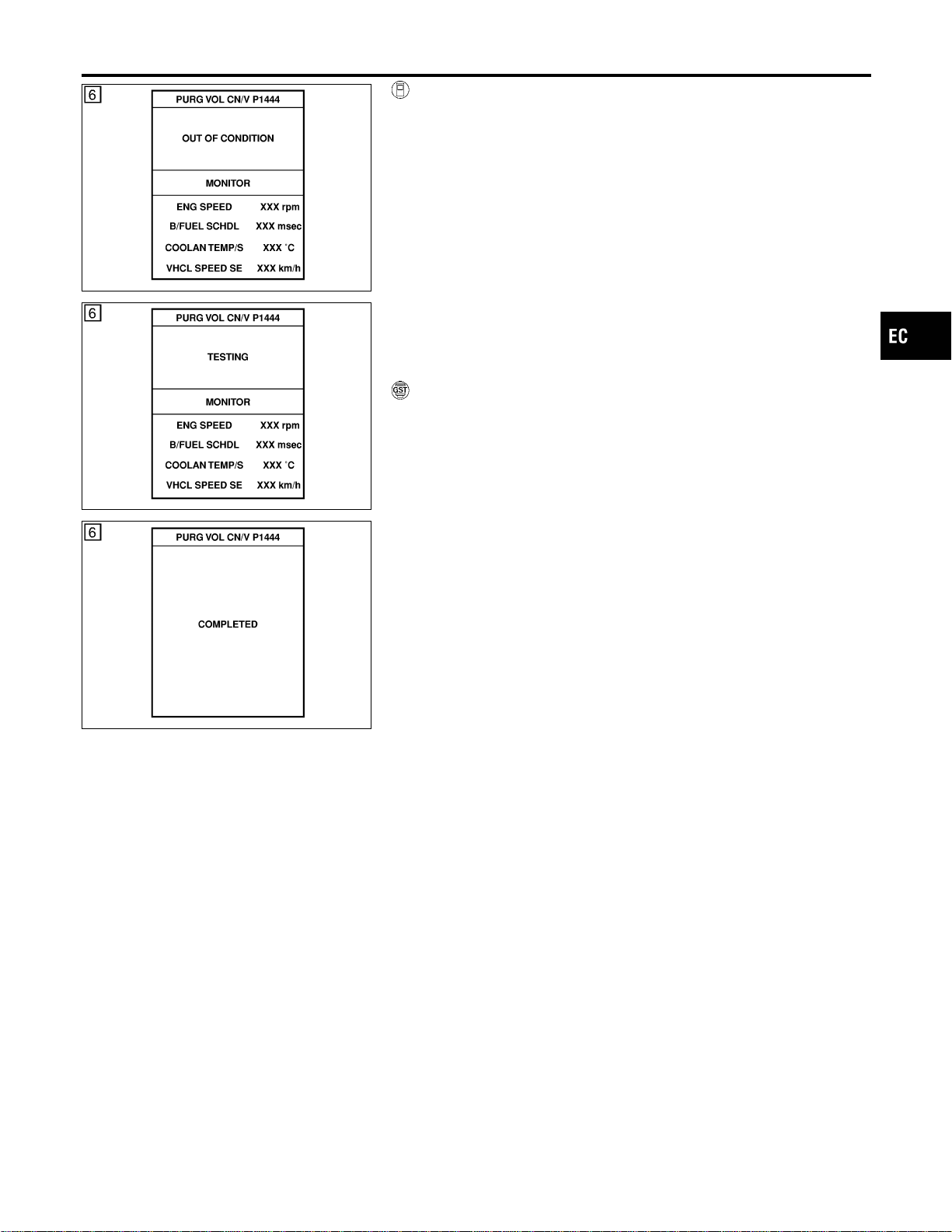
SEC143D
SEC144D
SEF237Y
WITH CONSULT-II
NFEC1093S01
1) Start engine and warm it up to normal operating temperature.
2) Turn ignition switch “OFF” and wait at least 10 seconds.
3) Turn ignition switch “ON”.
4) Select “PURG VOL CN/V P1444” of “EVAPORATIVE SYS-
TEM” in “DTC WORK SUPPORT” mode with CONSULT-II.
5) Touch “START”.
6) Start engine and let it idle until “TESTING” on CONSULT-II
changes to “COMPLETED”. (It will take for approximately 10
seconds.)
If “TESTING” is not displayed after 5 minutes, retry from
step 2.
7) Make sure that “OK” is displayed after touching “SELF-DIAG
RESULTS”. If “NG” is displayed, refer to “Diagnostic
Procedure”, EC-578.
WITH GST
NFEC1093S02
1) Start engine and warm it up to normal operating temperature.
2) Turn ignition switch “OFF” and wait at least 10 seconds.
3) Start engine and let it idle for at least 20 seconds.
4) Select “MODE 7” with GST.
5) If 1st trip DTC is detected, go to “Diagnostic Procedure”,
EC-578.
GI
MA
EM
LC
FE
CL
MT
AT
AX
SU
BR
ST
RS
BT
HA
SC
EL
IDX
DTC P1444 EVAP CANISTER PURGE VOLUME CONTROL SOLENOID VALVE
DTC Confirmation Procedure (Cont’d)
EC-575
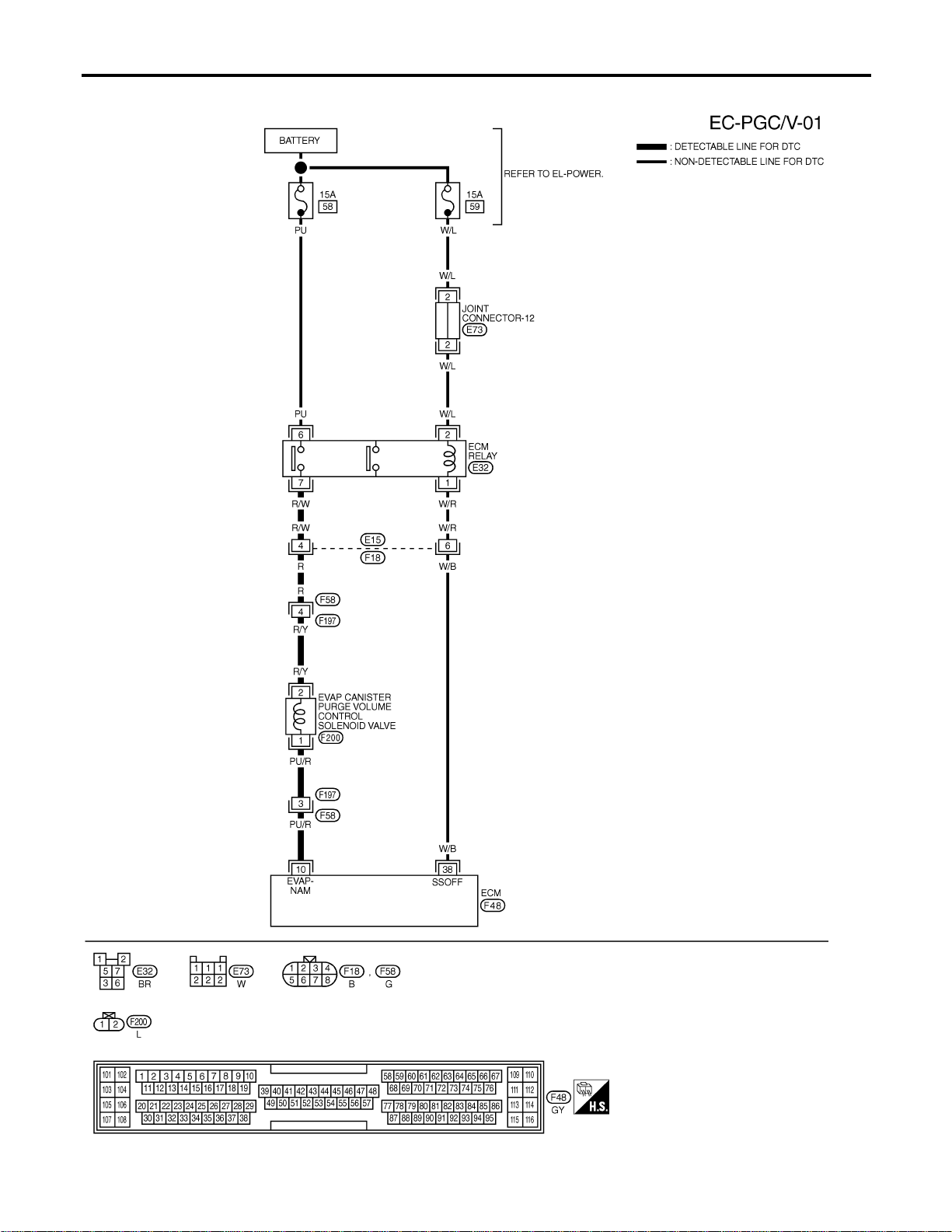
Wiring Diagram
NFEC1094
MEC494D
DTC P1444 EVAP CANISTER PURGE VOLUME CONTROL SOLENOID VALVE
Wiring Diagram
EC-576
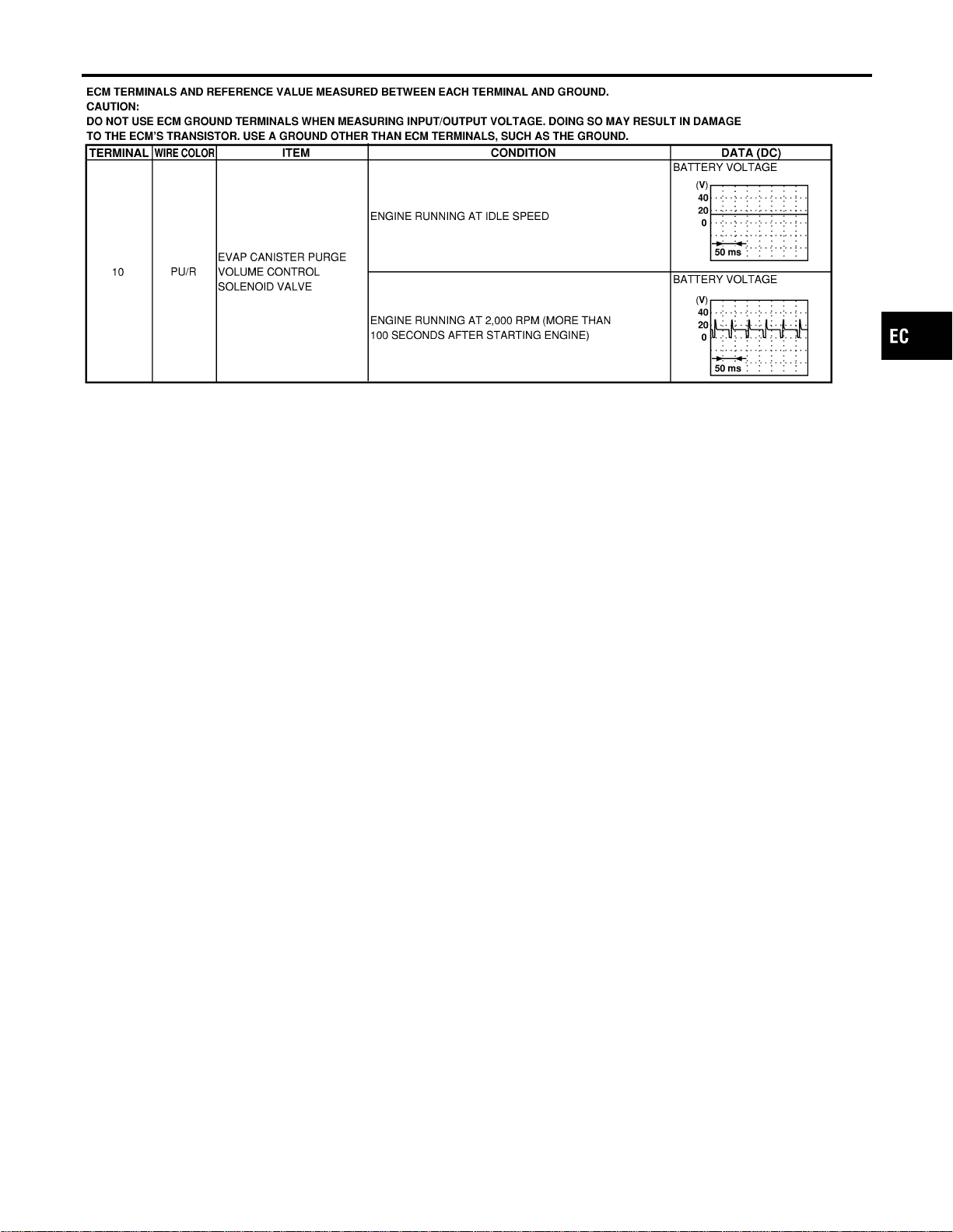
SEF800YB
GI
MA
EM
LC
FE
CL
MT
AT
AX
SU
BR
ST
RS
BT
HA
SC
EL
IDX
DTC P1444 EVAP CANISTER PURGE VOLUME CONTROL SOLENOID VALVE
Wiring Diagram (Cont’d)
EC-577
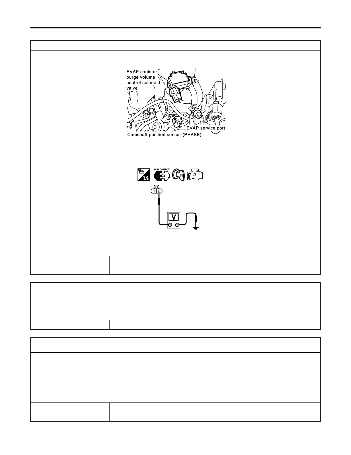
Diagnostic Procedure
NFEC1095
1 CHECK EVAP CANISTER PURGE VOLUME CONTROL SOLENOID VALVE POWER SUPPLY CIRCUIT
1. Turn ignition switch “OFF”.
2. Disconnect EVAP canister purge volume control solenoid valve harness connector.
SEC929C
3. Turn ignition switch “ON”.
4. Check voltage between EVAP canister purge volume control solenoid valve terminal 2 and engine ground with CON-
SULT-II or tester.
SEC062D
Voltage: Battery voltage
OK or NG
OK © GO TO 3.
NG © GO TO 2.
2 DETECT MALFUNCTIONING PART
Check the following.
I Harness connectors E15, F18
I Harness connectors F58, F197
I Harness for open or short between EVAP canister purge volume control solenoid valve and ECM relay
© Repair harness or connectors.
3 CHECK EVAP CANISTER PURGE VOLUME CONTROL SOLENOID VALVE OUTPUT SIGNAL CIRCUIT
FOR OPEN AND SHORT
1. Turn ignition switch “OFF”.
2. Disconnect ECM harness connector.
3. Check harness continuity between ECM terminal 10 and EVAP canister purge volume control solenoid valve terminal 1.
Refer to Wiring Diagram.
Continuity should exist.
4. Also check harness for short to ground and short to power.
OK or NG
OK © GO TO 5.
NG © GO TO 4.
DTC P1444 EVAP CANISTER PURGE VOLUME CONTROL SOLENOID VALVE
Diagnostic Procedure
EC-578
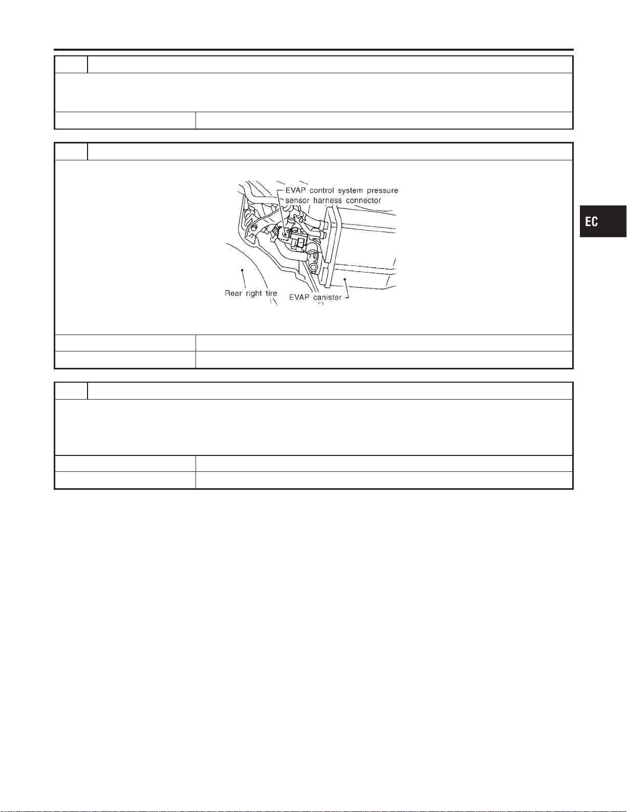
4 DETECT MALFUNCTIONING PART
Check the following.
I Harness connectors F197, F58
I Harness for open or short between ECM and EVAP canister purge volume control solenoid valve
© Repair open circuit or short to ground or short to power in harness or connectors.
5 CHECK EVAP CONTROL SYSTEM PRESSURE SENSOR HOSE
Check disconnection or improper connection of hose connected to EVAP control system pressure sensor.
SEF495R
OK or NG
OK © GO TO 6.
NG © Repair it.
6 CHECK EVAP CONTROL SYSTEM PRESSURE SENSOR CONNECTOR
1. Disconnect EVAP control system pressure sensor harness connector.
2. Check connectors for water.
Water should not exist.
OK or NG
OK © GO TO 7.
NG © Replace EVAP control system pressure sensor.
GI
MA
EM
LC
FE
CL
MT
AT
AX
SU
BR
ST
RS
BT
HA
SC
EL
IDX
DTC P1444 EVAP CANISTER PURGE VOLUME CONTROL SOLENOID VALVE
Diagnostic Procedure (Cont’d)
EC-579
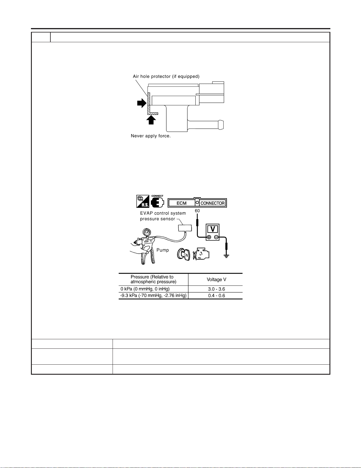
7 CHECK EVAP CONTROL SYSTEM PRESSURE SENSOR
1. Remove EVAP control system pressure sensor with its harness connector connected.
CAUTION:
Never apply force to the air hole protector of the sensor if equipped.
SEF799W
2. Remove hose from EVAP control system pressure sensor.
3. Turn ignition switch “ON”.
4. Use pump to apply vacuum and pressure to EVAP control system pressure sensor as shown in figure.
CAUTION:
I Always calibrate the vacuum pump gauge when using it.
I Do not apply below −20 kPa (−150 mmHg, −5.91 inHg) or over 20 kPa (150 mmHg, 5.91 inHg) of pressure.
5. Check input voltage between ECM terminal 60 and ground.
SEC908C
MTBL1159
CAUTION:
Discard and EVAP control system pressure sensor which has been dropped from a height of more than 0.5 m
(19.7 in) onto a hard surface such as a concrete floor; use a new one.
OK or NG
OK (With CONSULT-II) © GO TO 8.
OK (Without CONSULT-
II)
© GO TO 9.
NG © Replace EVAP control system pressure sensor.
DTC P1444 EVAP CANISTER PURGE VOLUME CONTROL SOLENOID VALVE
Diagnostic Procedure (Cont’d)
EC-580
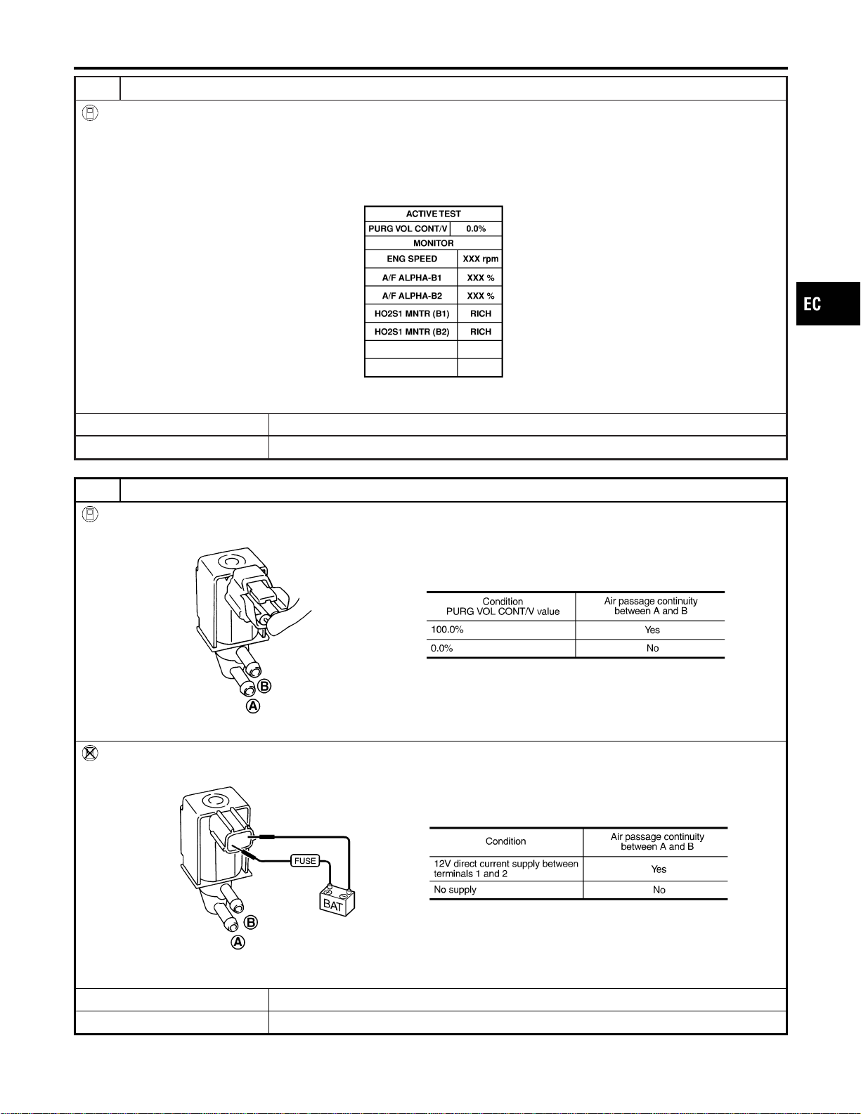
8 CHECK EVAP CANISTER PURGE VOLUME CONTROL SOLENOID VALVE
With CONSULT-II
1. Turn ignition switch “OFF”.
2. Reconnect harness connectors disconnected.
3. Start engine.
4. Perform “PURG VOL CONT/V” in “ACTIVE TEST” mode with CONSULT-II. Check that engine speed varies according
to the valve opening.
SEC142D
OK or NG
OK © GO TO 10.
NG © GO TO 9.
9 CHECK EVAP CANISTER PURGE VOLUME CONTROL SOLENOID VALVE
With CONSULT-II
Check air passage continuity of EVAP canister purge volume control solenoid valve under the following conditions.
SEF334X
Without CONSULT-II
Check air passage continuity of EVAP canister purge volume control solenoid valve under the following conditions.
SEF335X
OK or NG
OK © GO TO 10.
NG © Replace EVAP canister purge volume control solenoid valve.
GI
MA
EM
LC
FE
CL
MT
AT
AX
SU
BR
ST
RS
BT
HA
SC
EL
IDX
DTC P1444 EVAP CANISTER PURGE VOLUME CONTROL SOLENOID VALVE
Diagnostic Procedure (Cont’d)
EC-581
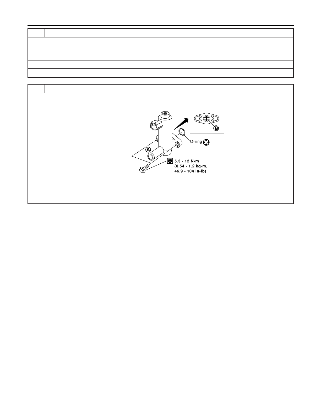
10 CHECK RUBBER TUBE FOR CLOGGING
1. Disconnect rubber tube connected to EVAP canister vent control valve.
2. Check the rubber tube for clogging.
OK or NG
OK © GO TO 11.
NG © Clean the rubber tube using an air blower.
11 CHECK EVAP CANISTER VENT CONTROL VALVE-I
1. Remove EVAP canister vent control valve from EVAP canister.
2. Check portion B of EVAP canister vent control valve for being rusted.
SEF376Z
OK or NG
OK © GO TO 12.
NG © Replace EVAP canister vent control valve.
DTC P1444 EVAP CANISTER PURGE VOLUME CONTROL SOLENOID VALVE
Diagnostic Procedure (Cont’d)
EC-582
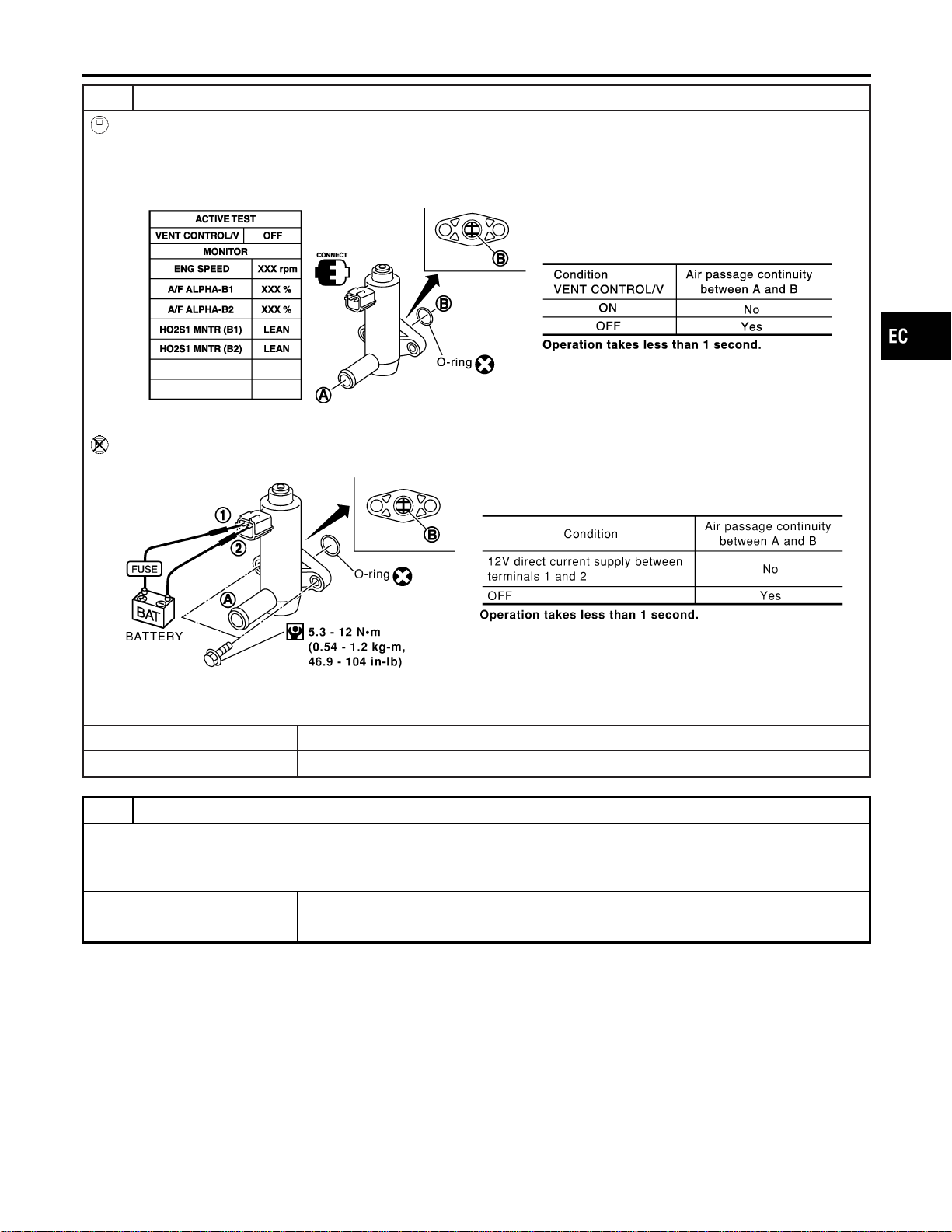
12 CHECK EVAP CANISTER VENT CONTROL VALVE-II
With CONSULT-II
1. Reconnect harness connectors disconnected.
2. Turn ignition switch “ON”.
3. Perform “VENT CONTROL/V” in “ACTIVE TEST” mode.
4. Check air passage continuity and operation delay time.
SEC158D
Without CONSULT-II
Check air passage continuity and operation delay time under the following conditions.
SEF378Z
Make sure new O-ring is installed properly.
OK or NG
OK © GO TO 14.
NG © GO TO 13.
13 CHECK EVAP CANISTER VENT CONTROL VALVE-III
1. Clean the air passage (Portion A to B) of EVAP canister vent control valve using an air blower.
2. Perform procedure 9 again.
OK or NG
OK © GO TO 14.
NG © Replace EVAP canister vent control valve.
GI
MA
EM
LC
FE
CL
MT
AT
AX
SU
BR
ST
RS
BT
HA
SC
EL
IDX
DTC P1444 EVAP CANISTER PURGE VOLUME CONTROL SOLENOID VALVE
Diagnostic Procedure (Cont’d)
EC-583
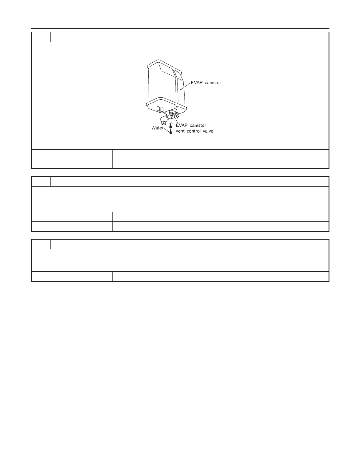
14 CHECK IF EVAP CANISTER SATURATED WITH WATER
1. Remove EVAP canister with EVAP canister vent control valve attached.
2. Check if water will drain from the EVAP canister.
SEF596U
YesorNo
Yes © GO TO 15.
No © GO TO 18.
15 CHECK EVAP CANISTER
Weigh the EVAP canister with the EVAP canister vent control valve attached.
The weight should be less than 1.8 kg (4.0 lb).
OK or NG
OK © GO TO 17.
NG © GO TO 16.
16 DETECT MALFUNCTIONING PART
Check the following.
I EVAP canister for damage
I EVAP hose between EVAP canister and water separater for clogging or poor connection
© Repair hose or replace EVAP canister.
DTC P1444 EVAP CANISTER PURGE VOLUME CONTROL SOLENOID VALVE
Diagnostic Procedure (Cont’d)
EC-584
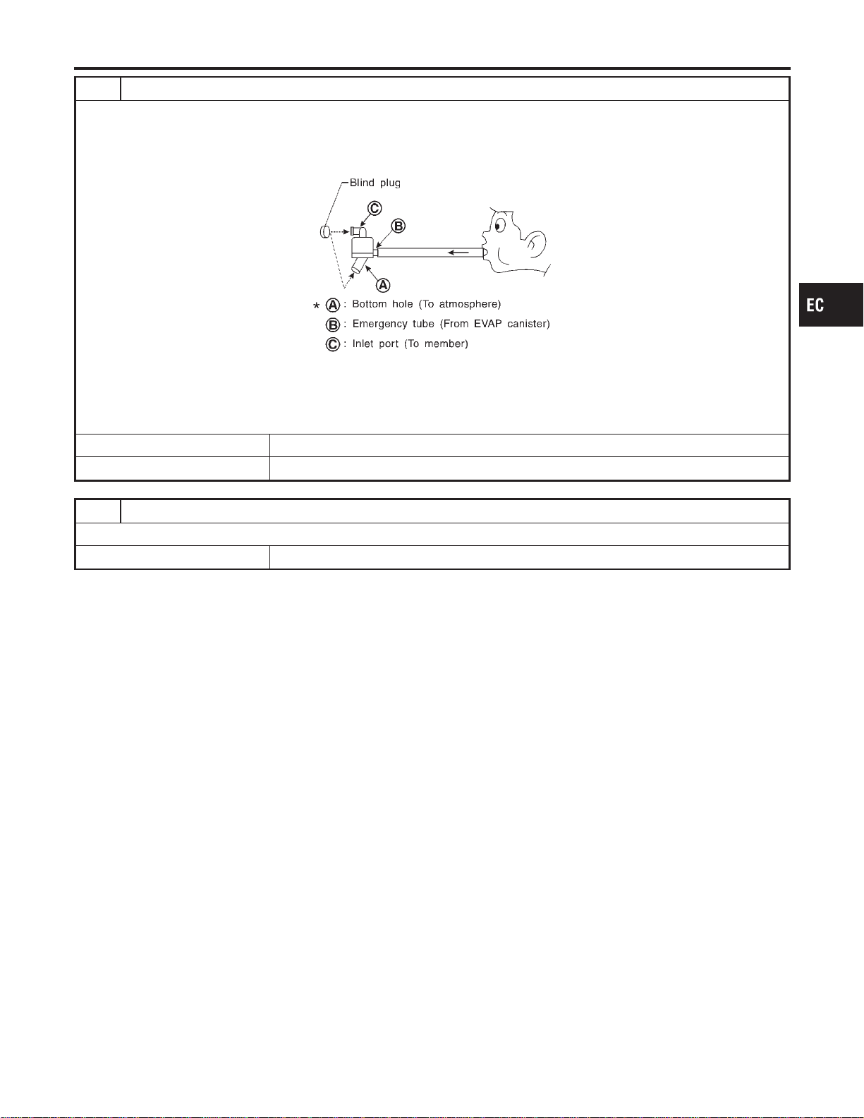
17 CHECK WATER SEPARATOR
1. Check visually for insect nests in the water separator air inlet.
2. Check visually for cracks or flaws in the appearance.
3. Check visually for cracks or flaws in the hose.
4. Check that A and C are not clogged by blowing air into B with A, and then C plugged.
SEF829T
5. In case of NG in items2-4,replace the parts.
NOTE:
Do not disassemble water separator.
OK or NG
OK © GO TO 18.
NG © Clean or replace water separator.
18 CHECK INTERMITTENT INCIDENT
Refer to “TROUBLE DIAGNOSIS FOR INTERMITTENT INCIDENT”, EC-156.
© INSPECTION END
GI
MA
EM
LC
FE
CL
MT
AT
AX
SU
BR
ST
RS
BT
HA
SC
EL
IDX
DTC P1444 EVAP CANISTER PURGE VOLUME CONTROL SOLENOID VALVE
Diagnostic Procedure (Cont’d)
EC-585
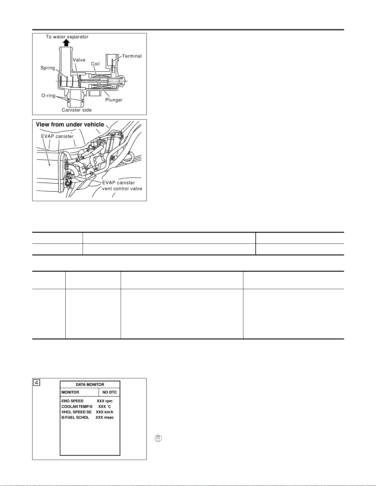
SEF381Z
SEF267X
Component Description
NFEC1096
The EVAP canister vent control valve is located on the EVAP can-
ister and is used to seal the canister vent.
This solenoid valve responds to signals from the ECM. When the
ECM sends an ON signal, the coil in the solenoid valve is ener-
gized. A plunger will then move to seal the canister vent. The abil-
ity to seal the vent is necessary for the on board diagnosis of other
evaporative emission control system components.
This solenoid valve is used only for diagnosis, and usually remains
opened.
When the vent is closed, under normal purge conditions, the
evaporative emission control system is depressurized and allows
“EVAP Control System (Small Leak)” diagnosis.
CONSULT-II Reference Value in Data Monitor
Mode
NFEC1097
Specification data are reference values.
MONITOR ITEM CONDITION SPECIFICATION
VENT CONT/V I Ignition switch: ON OFF
On Board Diagnosis Logic
NFEC1099
DTC No.
Trouble diagnosis
name
DTC Detecting Condition Possible Cause
P1446
1446
EVAP canister vent
control valve closed
EVAP canister vent control valve remains closed
under specified driving conditions.
I EVAP canister vent control valve
I EVAP control system pressure sensor
and the circuit
I Blocked rubber tube to EVAP canister
vent control valve
I Water separator
I EVAP canister is saturated with water.
PBIB0164E
DTC Confirmation Procedure
NFEC1100
CAUTION:
Always drive vehicle at a safe speed.
NOTE:
If “DTC Confirmation Procedure” has been previously conducted,
always turn ignition switch “OFF” and wait at least 10 seconds
before conducting the next test.
WITH CONSULT-II
NFEC1100S01
1) Turn ignition switch “ON”.
2) Select “DATA MONITOR” mode with CONSULT-II.
DTC P1446 EVAP CANISTER VENT CONTROL VALVE
Component Description
EC-586

3) Start engine.
4) Drive vehicle at a speed of approximately 80 km/h (50 MPH)
for a maximum of 15 minutes.
NOTE:
If a malfunction exists, NG result may be displayed quicker.
5) If 1st trip DTC is detected, go to “Diagnostic Procedure”,
EC-589.
WITH GST
NFEC1100S02
Follow the procedure “WITH CONSULT-II” above.
GI
MA
EM
LC
FE
CL
MT
AT
AX
SU
BR
ST
RS
BT
HA
SC
EL
IDX
DTC P1446 EVAP CANISTER VENT CONTROL VALVE
DTC Confirmation Procedure (Cont’d)
EC-587
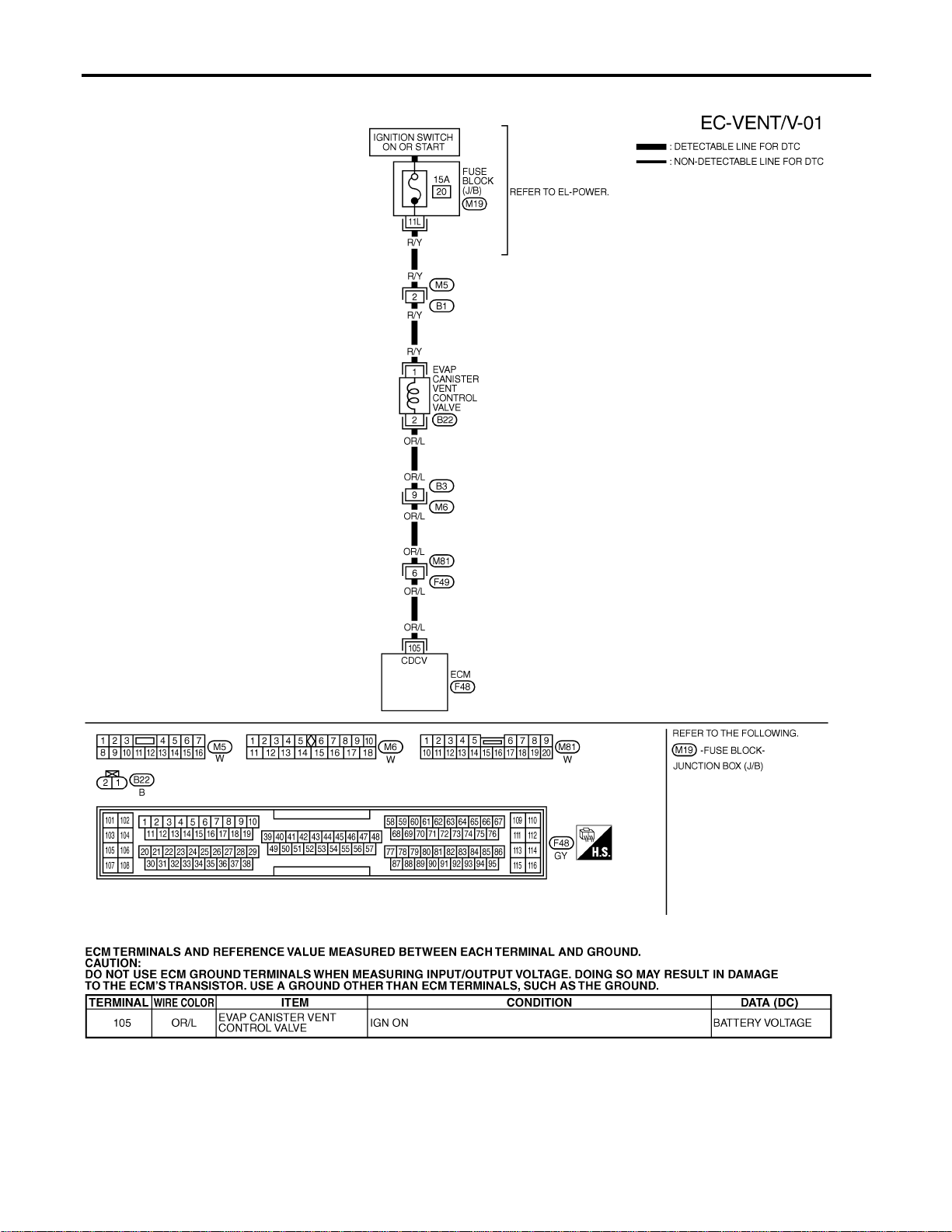
Wiring Diagram
=NFEC1101
MEC495D
SEF668XC
DTC P1446 EVAP CANISTER VENT CONTROL VALVE
Wiring Diagram
EC-588
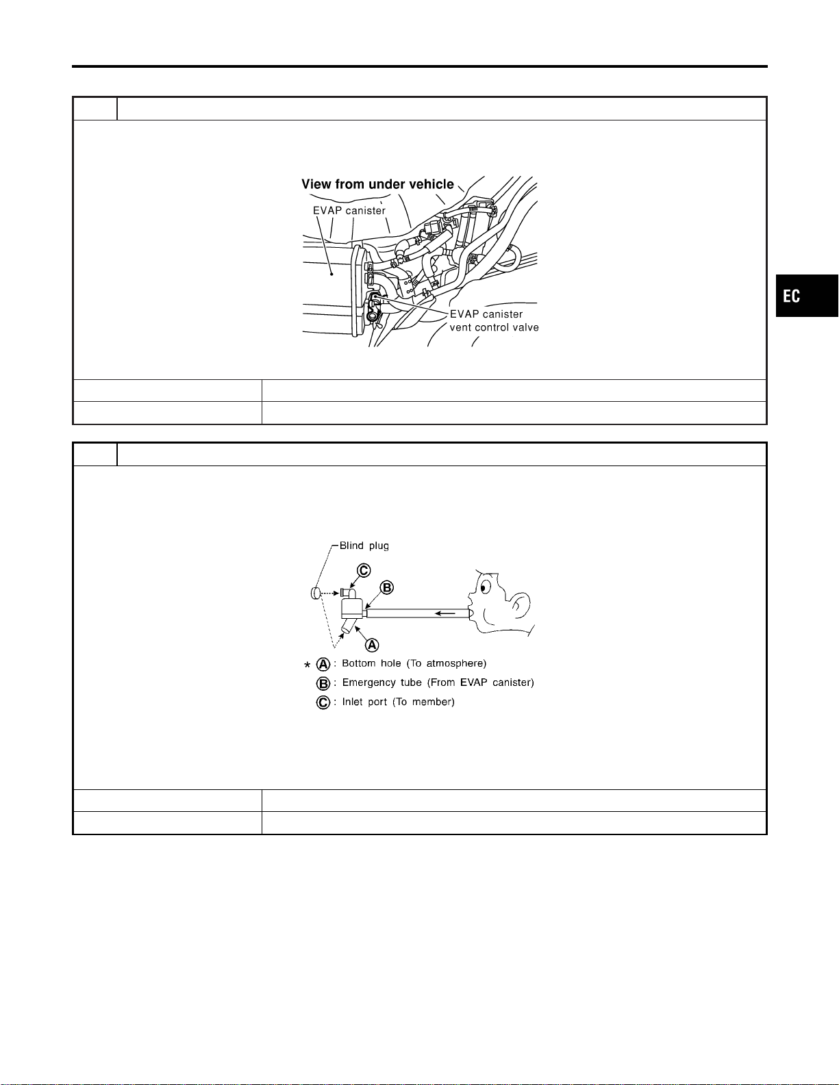
Diagnostic Procedure
NFEC1102
1 CHECK RUBBER TUBE
1. Turn ignition switch “OFF”.
2. Disconnect rubber tube connected to EVAP canister vent control valve.
3. Check the rubber tube for clogging.
SEF267X
OK or NG
OK © GO TO 2.
NG © Clean rubber tube using an air blower.
2 CHECK WATER SEPARATOR
1. Check visually for insect nests in the water separator air inlet.
2. Check visually for cracks or flaws in the appearance.
3. Check visually for cracks or flaws in the hose.
4. Check that A and C are not clogged by blowing air into B with A, and then C plugged.
SEF829T
5. In case of NG in items2-4,replace the parts.
NOTE:
Do not disassemble water separator.
OK or NG
OK © GO TO 3.
NG © Clean or replace water separator.
GI
MA
EM
LC
FE
CL
MT
AT
AX
SU
BR
ST
RS
BT
HA
SC
EL
IDX
DTC P1446 EVAP CANISTER VENT CONTROL VALVE
Diagnostic Procedure
EC-589
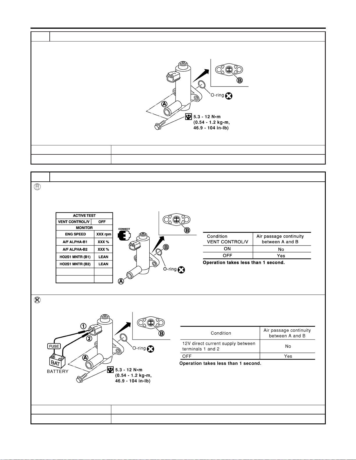
3 CHECK EVAP CANISTER VENT CONTROL VALVE-I
1. Remove EVAP canister vent control valve from EVAP canister.
2. Check portion B of EVAP canister vent control valve for being rusted.
SEF376Z
OK or NG
OK © GO TO 4.
NG © Replace EVAP canister vent control valve.
4 CHECK EVAP CANISTER VENT CONTROL VALVE-II
With CONSULT-II
1. Turn ignition switch ON.
2. Perform “VENT CONTROL/V” in “ACTIVE TEST” mode.
3. Check air passage continuity and operation delay time.
SEC158D
Without CONSULT-II
Check air passage continuity and operation delay time under the following conditions.
SEF378Z
Make sure new O-ring is installed properly.
OK or NG
OK © GO TO 6.
NG © GO TO 5.
DTC P1446 EVAP CANISTER VENT CONTROL VALVE
Diagnostic Procedure (Cont’d)
EC-590
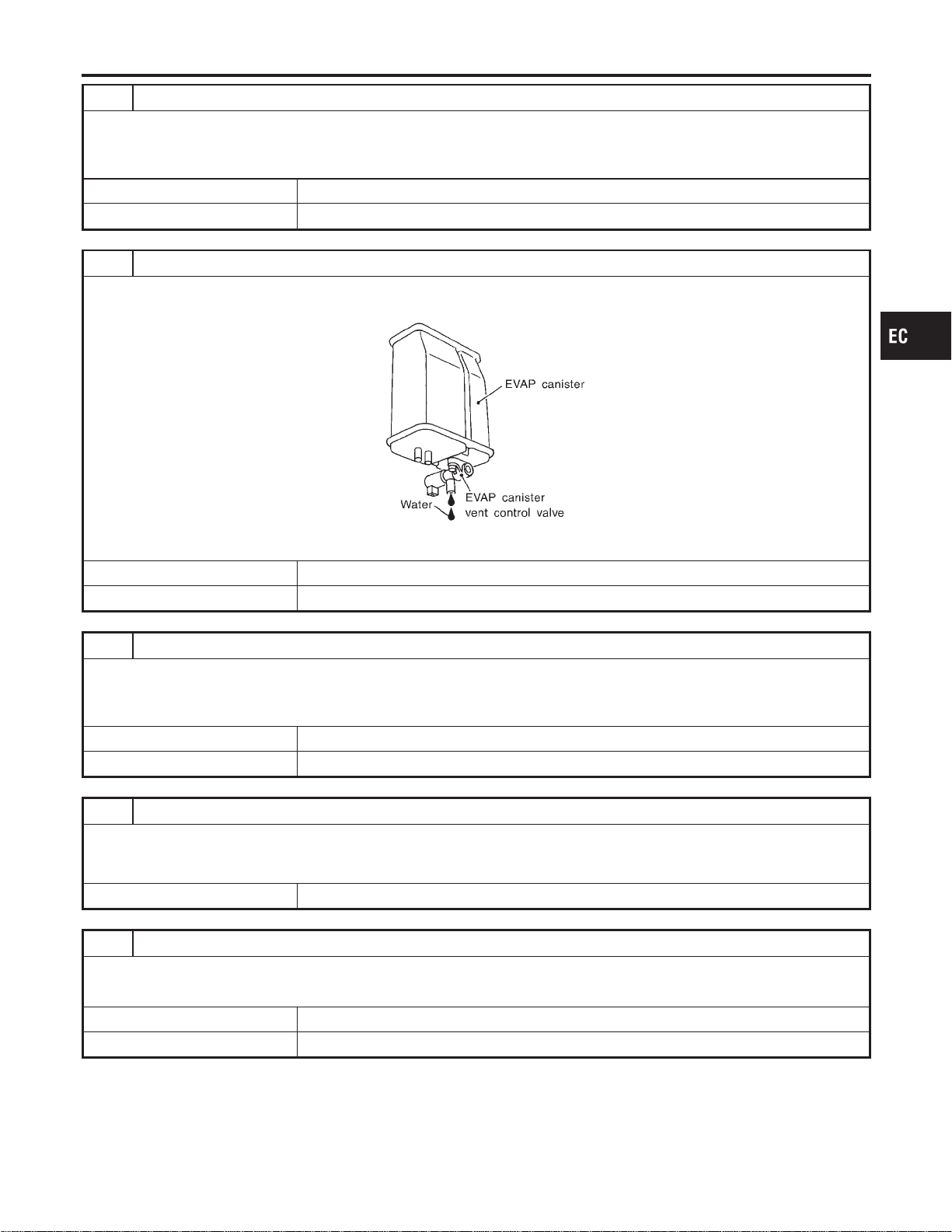
5 CHECK EVAP CANISTER VENT CONTROL VALVE-III
1. Clean the air passage (Portion A to B) of EVAP canister vent control valve using an air blower.
2. Perform the procedure 4 again.
OK or NG
OK © GO TO 6.
NG © Replace EVAP canister vent control valve.
6 CHECK IF EVAP CANISTER SATURATED WITH WATER
1. Remove EVAP canister with EVAP canister vent control valve attached.
2. Check if water will drain from the EVAP canister.
SEF596U
YesorNo
Yes © GO TO 7.
No © GO TO 9.
7 CHECK EVAP CANISTER
Weigh the EVAP canister with the EVAP canister vent control valve attached.
The weight should be less than 1.8 kg (4.0 lb).
OK or NG
OK © GO TO 9.
NG © GO TO 8.
8 DETECT MALFUNCTIONING PART
Check the following.
I EVAP canister for damage
I EVAP hose between EVAP canister and water separator for clogging or poor connection
© Repair hose or replace EVAP canister.
9 CHECK EVAP CONTROL SYSTEM PRESSURE SENSOR HOSE
Check disconnection or improper connection of hose connected to EVAP control system pressure sensor.
OK or NG
OK © GO TO 10.
NG © Repair it.
GI
MA
EM
LC
FE
CL
MT
AT
AX
SU
BR
ST
RS
BT
HA
SC
EL
IDX
DTC P1446 EVAP CANISTER VENT CONTROL VALVE
Diagnostic Procedure (Cont’d)
EC-591
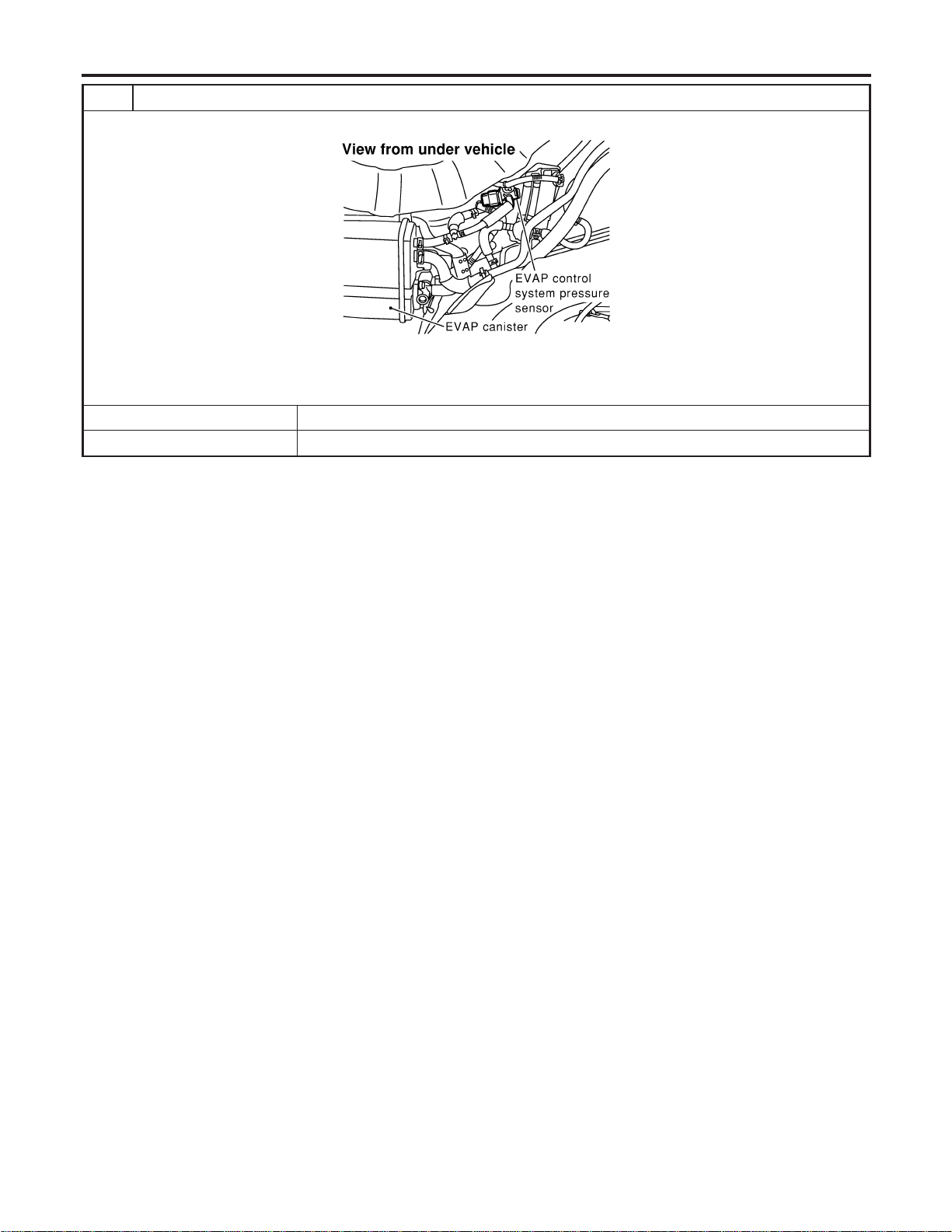
10 CHECK EVAP CONTROL SYSTEM PRESSURE SENSOR CONNECTOR
1. Disconnect EVAP control system pressure sensor harness connector.
SEF268X
2. Check connectors for water.
Water should not exist.
OK or NG
OK © GO TO 11.
NG © Replace EVAP control system pressure sensor.
DTC P1446 EVAP CANISTER VENT CONTROL VALVE
Diagnostic Procedure (Cont’d)
EC-592
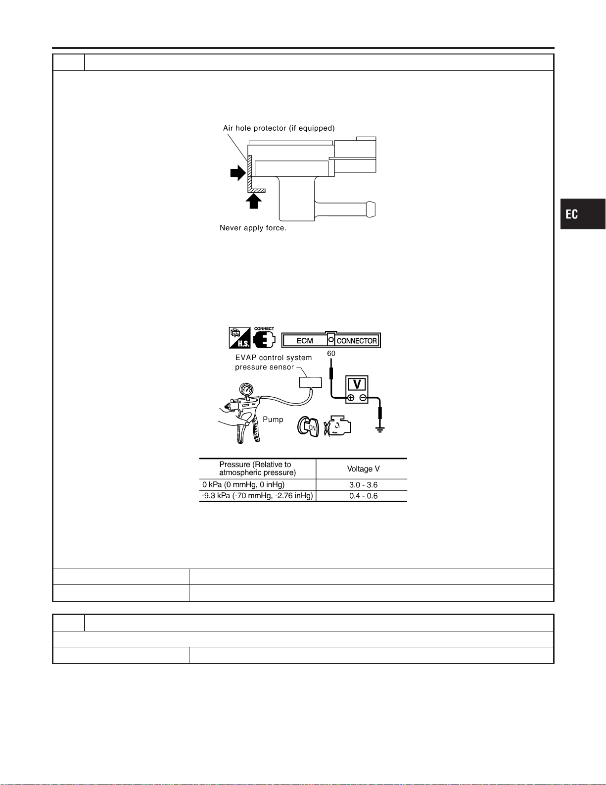
11 CHECK EVAP CONTROL SYSTEM PRESSURE SENSOR
1. Remove EVAP control system pressure sensor with its harness connector connected.
CAUTION:
Never apply force to the air hole protector of the sensor if equipped.
SEF799W
2. Remove hose from EVAP control system pressure sensor.
3. Turn ignition switch “ON”.
4. Use pump to apply vacuum and pressure to EVAP control system pressure sensor as shown in figure.
CAUTION:
I Always calibrate the vacuum pump gauge when using it.
I Do not apply below −20 kPa (−150 mmHg, −5.91 inHg) or over 20 kPa (150 mmHg, 5.91 inHg) of pressure.
5. Check input voltage between ECM terminal 60 and ground.
SEC908C
MTBL1159
CAUTION:
Discard and EVAP control system pressure sensor which has been dropped from a height of more than 0.5 m
(19.7 in) onto a hard surface such as a concrete floor; use a new one.
OK or NG
OK © GO TO 12.
NG © Replace EVAP control system pressure sensor.
12 CHECK INTERMITTENT INCIDENT
Refer to “TROUBLE DIAGNOSIS FOR INTERMITTENT INCIDENT”, EC-156.
© INSPECTION END
GI
MA
EM
LC
FE
CL
MT
AT
AX
SU
BR
ST
RS
BT
HA
SC
EL
IDX
DTC P1446 EVAP CANISTER VENT CONTROL VALVE
Diagnostic Procedure (Cont’d)
EC-593
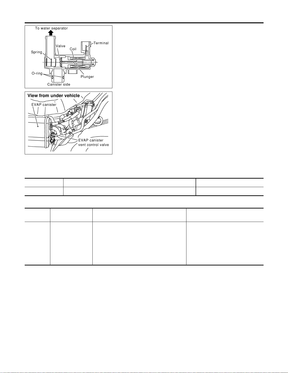
SEF381Z
SEF267X
Component Description
NFEC1103
NOTE:
If DTC P1448 is displayed with P0442, perform trouble diagno-
sis for DTC P1448 first.
The EVAP canister vent control valve is located on the EVAP can-
ister and is used to seal the canister vent.
This solenoid valve responds to signals from the ECM. When the
ECM sends an ON signal, the coil in the solenoid valve is ener-
gized. A plunger will then move to seal the canister vent. The abil-
ity to seal the vent is necessary for the on board diagnosis of other
evaporative emission control system components.
This solenoid valve is used only for diagnosis, and usually remains
opened.
When the vent is closed, under normal purge conditions, the
evaporative emission control system is depressurized and allows
“EVAP Control System (Small Leak)” diagnosis.
CONSULT-II Reference Value in Data Monitor
Mode
NFEC1104
Specification data are reference values.
MONITOR ITEM CONDITION SPECIFICATION
VENT CONT/V I Ignition switch: ON OFF
On Board Diagnosis Logic
NFEC1106
DTC No.
Trouble diagnosis
name
DTC Detecting Condition Possible Cause
P1448
1448
EVAP canister vent
control valve open
EVAP canister vent control valve remains opened
under specified driving conditions.
I EVAP canister vent control valve
I EVAP control system pressure sensor
and circuit
I Blocked rubber tube to EVAP canister
vent control valve
I Water separator
I EVAP canister is saturated with water.
I Vacuum cut valve
DTC Confirmation Procedure
NFEC1107
NOTE:
I If DTC P1448 is displayed with P0442, perform trouble
diagnosis for DTC P1448 first.
I If “DTC Confirmation Procedure” has been previously
conducted, always turn ignition switch “OFF” and wait at least
10 seconds before conducting the next test.
DTC P1448 EVAP CANISTER VENT CONTROL VALVE
Component Description
EC-594
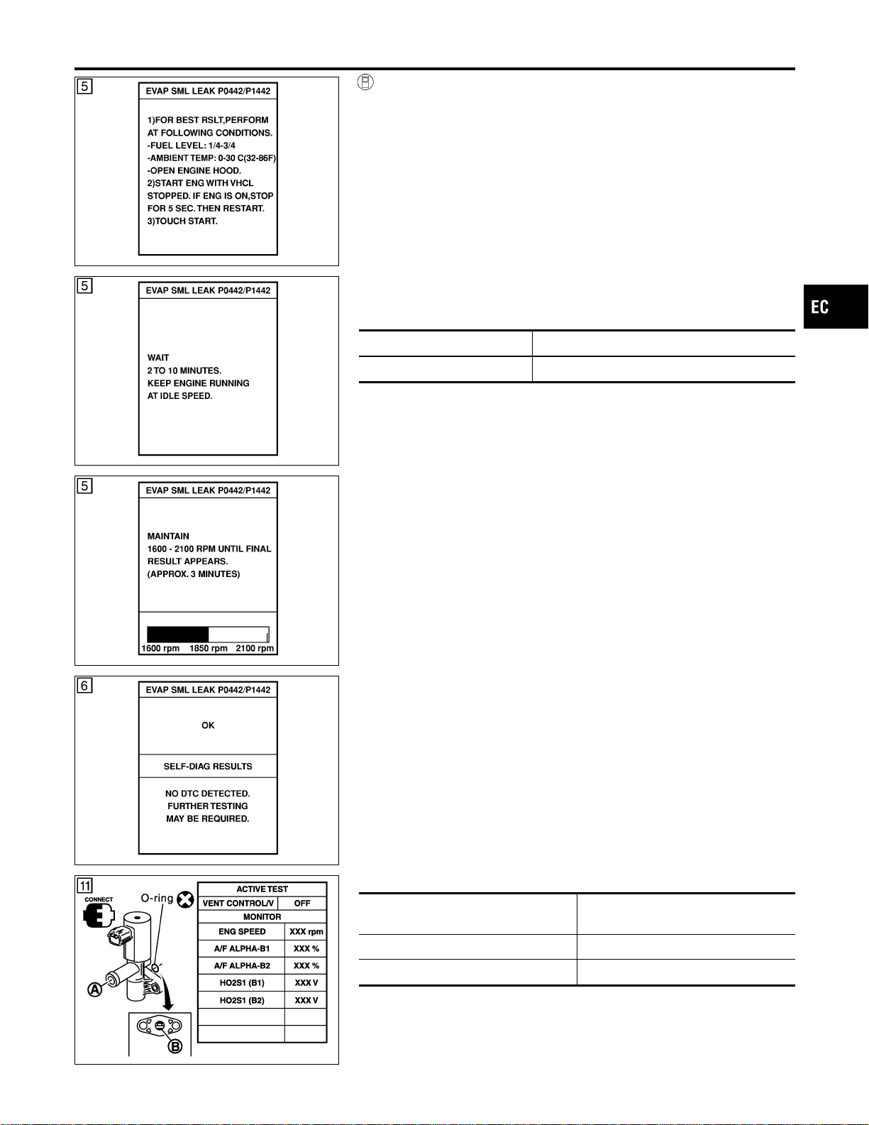
SEC760C
SEC761C
SEC762C
SEC763C
WITH CONSULT-II
NFEC1107S01
TESTING CONDITION:
I Perform “DTC WORK SUPPORT” when the fuel level is
between 1/4 to 3/4 full and vehicle is placed on flat level
surface.
I Always perform test at a temperature of 0 to 30°C (32 to
86°F).
I Open engine hood before conducting the following proce-
dure.
1) Turn ignition switch “ON”.
2) Turn ignition switch “OFF” and wait at least 10 seconds.
3) Turn ignition switch “ON” and select “DATA MONITOR” mode
with CONSULT-II.
4) Make sure that the following conditions are met.
COOLAN TEMP/S 0 - 70°C (32 - 158°F)
INT/A TEMP SE 0 - 30°C (32 - 86°F)
5) Select “EVP SML LEAK P0442/P1442” of “EVAPORATIVE
SYSTEM” in “DTC WORK SUPPORT” mode with CONSULT-
II.
Follow the instruction displayed.
NOTE:
If the engine speed cannot be maintained within the range dis-
played on the CONSULT-II screen, go to “Basic Inspection”,
EC-123.
6) Make sure that “OK” is displayed.
If “NG” is displayed, go to the following step.
NOTE:
Make sure that EVAP hoses are connected to EVAP canister
purge volume control solenoid valve properly.
7) Stop engine and wait at least 10 seconds, then turn “ON”.
8) Disconnect hose from water separator.
9) Select “VENT CONTROL/V” of “ACTIVE TEST” mode with
CONSULT-II.
10) Touch “ON” and “OFF” alternately.
PBIB0153E
11) Make sure the following.
Condition
VENT CONTROL/V
Air passage continuity
between A and B
ON No
OFF Yes
If the result is NG, go to “Diagnostic Procedure”, EC-598.
If the result is OK, go to “Diagnostic Procedure” for DTC
P0442, EC-361.
GI
MA
EM
LC
FE
CL
MT
AT
AX
SU
BR
ST
RS
BT
HA
SC
EL
IDX
DTC P1448 EVAP CANISTER VENT CONTROL VALVE
DTC Confirmation Procedure (Cont’d)
EC-595
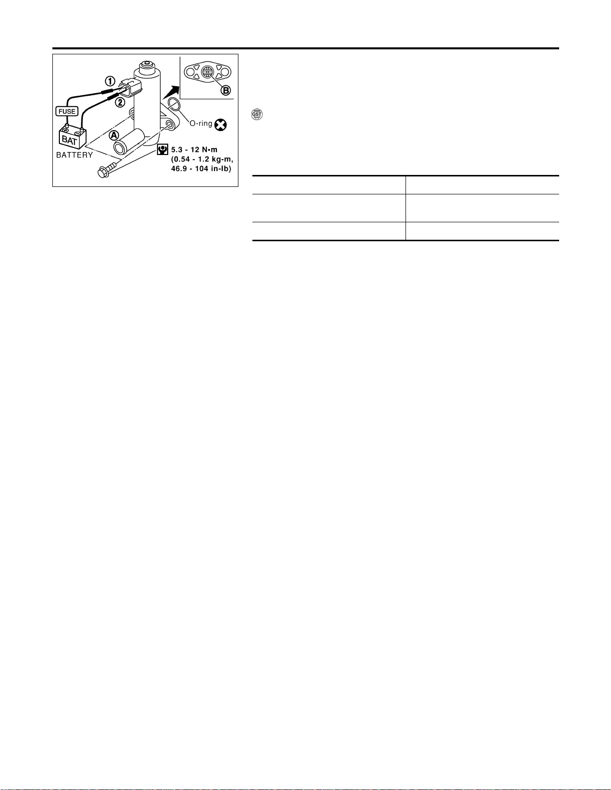
SEF380Z
Overall Function Check
NFEC1108
Use this procedure to check the overall function of the EVAP can-
ister vent control valve circuit. During this check, a DTC might not
be confirmed.
WITH GST
NFEC1108S01
1) Disconnect hose from water separator.
2) Disconnect EVAP canister vent control valve harness connec-
tor.
3) Verify the following.
Condition Air passage continuity
12V direct current supply between ter-
minals 1 and 2
No
No supply Yes
If the result is NG, go to “Diagnostic Procedure”, EC-598.
If the result is OK, go to “Diagnostic Procedure” for DTC
P0442, EC-361.
DTC P1448 EVAP CANISTER VENT CONTROL VALVE
Overall Function Check
EC-596
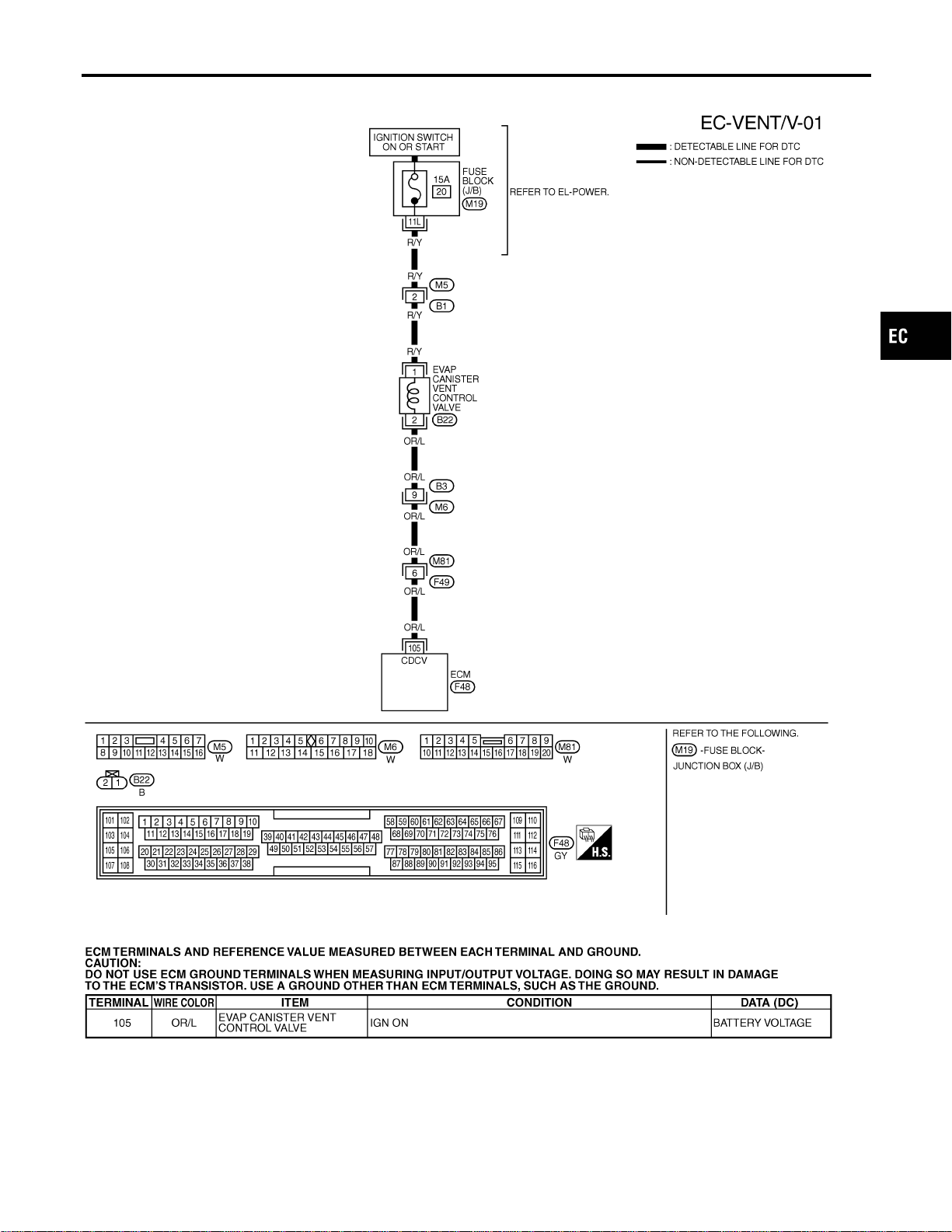
Wiring Diagram
NFEC1109
MEC495D
SEF668XC
GI
MA
EM
LC
FE
CL
MT
AT
AX
SU
BR
ST
RS
BT
HA
SC
EL
IDX
DTC P1448 EVAP CANISTER VENT CONTROL VALVE
Wiring Diagram
EC-597
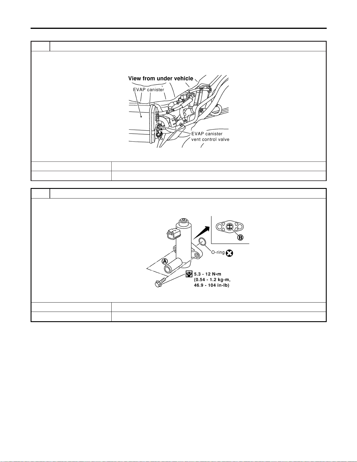
Diagnostic Procedure
NFEC1110
1 CHECK RUBBER TUBE
1. Turn ignition switch “OFF”.
2. Disconnect rubber tube connected to EVAP canister vent control valve.
3. Check the rubber tube for clogging.
SEF267X
OK or NG
OK © GO TO 2.
NG © Clean rubber tube using an air blower.
2 CHECK EVAP CANISTER VENT CONTROL VALVE-I
1. Remove EVAP canister vent control valve from EVAP canister.
2. Check portion B of EVAP canister vent control valve for being rusted.
SEF376Z
OK or NG
OK © GO TO 3.
NG © Replace EVAP canister vent control valve.
DTC P1448 EVAP CANISTER VENT CONTROL VALVE
Diagnostic Procedure
EC-598
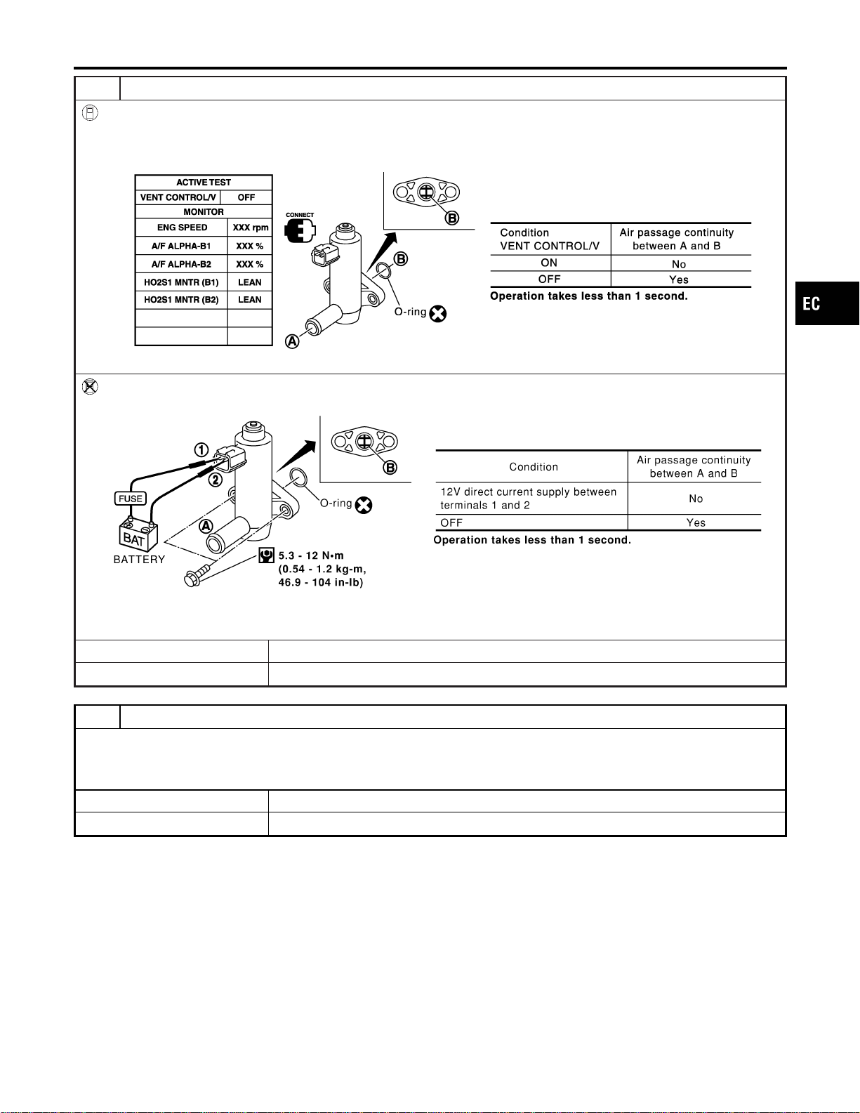
3 CHECK EVAP CANISTER VENT CONTROL VALVE-II
With CONSULT-II
1. Turn ignition switch ON.
2. Perform “VENT CONTROL/V” in “ACTIVE TEST” mode.
3. Check air passage continuity and operation delay time.
SEC158D
Without CONSULT-II
Check air passage continuity and operation delay time under the following conditions.
SEF378Z
Make sure new O-ring is installed properly.
OK or NG
OK © GO TO 5.
NG © GO TO 4.
4 CHECK EVAP CANISTER VENT CONTROL VALVE-III
1. Clean the air passage (Portion A to B) of EVAP canister vent control valve using an air blower.
2. Perform Test No. 3 again.
OK or NG
OK © GO TO 5.
NG © Replace EVAP canister vent control valve.
GI
MA
EM
LC
FE
CL
MT
AT
AX
SU
BR
ST
RS
BT
HA
SC
EL
IDX
DTC P1448 EVAP CANISTER VENT CONTROL VALVE
Diagnostic Procedure (Cont’d)
EC-599
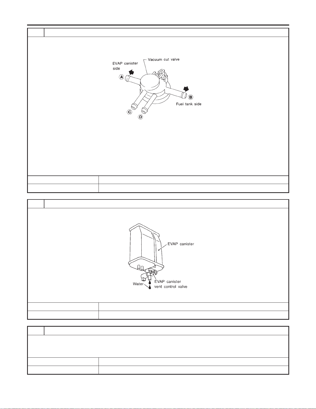
5 CHECK VACUUM CUT VALVE
1. Turn ignition switch OFF.
2. Remove vacuum cut valve.
3. Check vacuum cut valve as follows:
SEF379Q
a. Plug port C and D with fingers.
b. Apply vacuum to port A and check that there is no suction from port B.
c. Apply vacuum to port B and check that there is suction from port A.
d. Blow air in port B and check that there is a resistance to flow out of port A.
e. Open port C and D.
f. Blow air in port A check that air flows freely out of port C.
g. Blow air in port B check that air flows freely out of port D.
OK or NG
OK © GO TO 6.
NG © Replace vacuum cut valve.
6 CHECK IF EVAP CANISTER SATURATED WITH WATER
1. Remove EVAP canister with EVAP canister vent control valve attached.
2. Check if water will drain from the EVAP canister.
SEF596U
YesorNo
Yes © GO TO 7.
No © GO TO 9.
7 CHECK EVAP CANISTER
Weigh the EVAP canister with the EVAP canister vent control valve attached.
The weight should be less than 1.8 kg (4.0 lb).
OK or NG
OK © GO TO 9.
NG © GO TO 8.
DTC P1448 EVAP CANISTER VENT CONTROL VALVE
Diagnostic Procedure (Cont’d)
EC-600
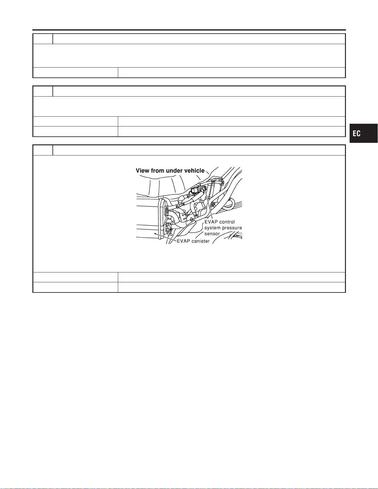
8 DETECT MALFUNCTIONING PART
Check the following.
I EVAP canister for damage
I EVAP hose between EVAP canister and water separator for clogging or poor connection
© Repair hose or replace EVAP canister.
9 CHECK EVAP CONTROL SYSTEM PRESSURE SENSOR HOSE
Check disconnection or improper connection of hose connected to EVAP control system pressure sensor.
OK or NG
OK © GO TO 10.
NG © Repair it.
10 CHECK EVAP CONTROL SYSTEM PRESSURE SENSOR CONNECTOR
1. Disconnect EVAP control system pressure sensor harness connector.
SEF268X
2. Check connectors for water.
Water should not exist.
OK or NG
OK © GO TO 11.
NG © Replace EVAP control system pressure sensor.
GI
MA
EM
LC
FE
CL
MT
AT
AX
SU
BR
ST
RS
BT
HA
SC
EL
IDX
DTC P1448 EVAP CANISTER VENT CONTROL VALVE
Diagnostic Procedure (Cont’d)
EC-601
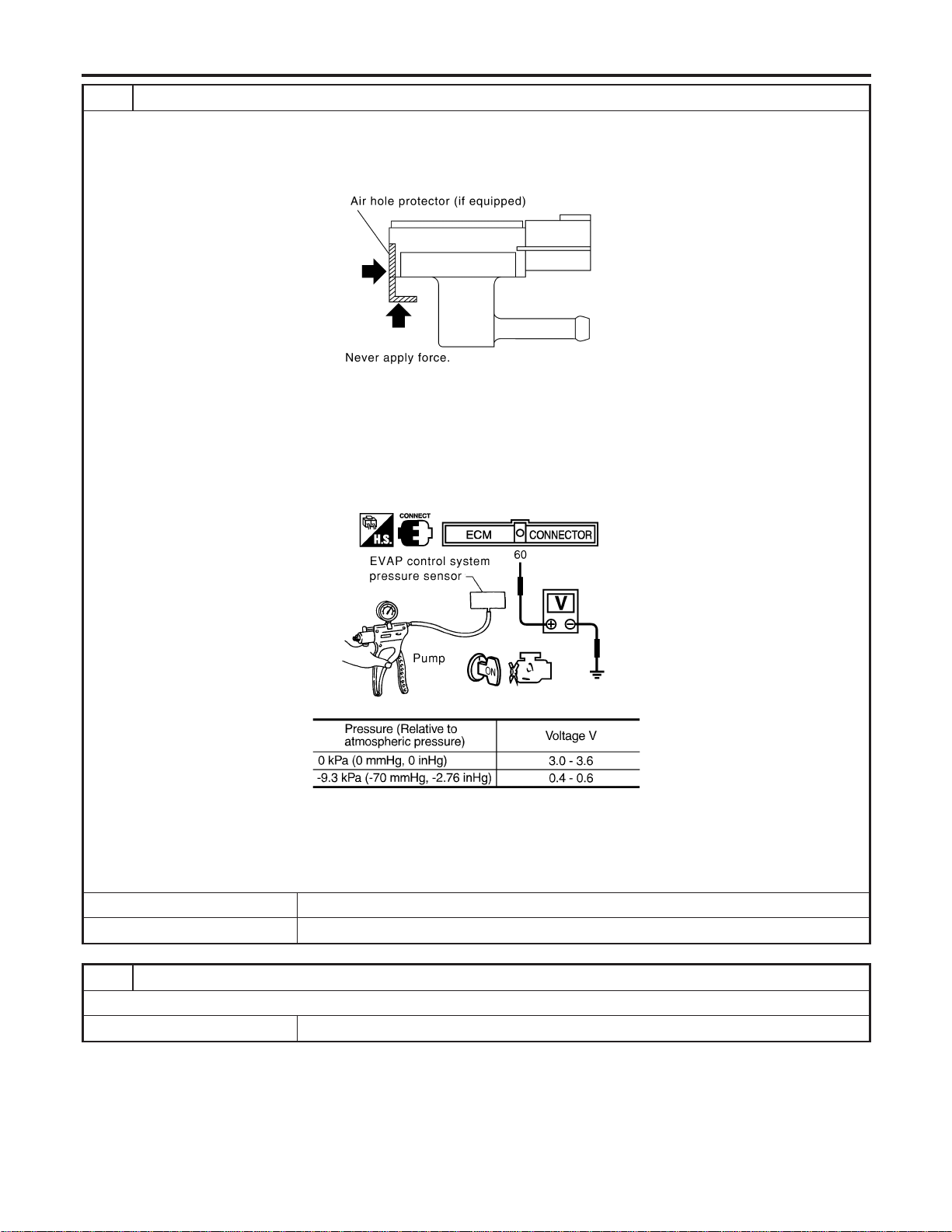
11 CHECK EVAP CONTROL SYSTEM PRESSURE SENSOR
1. Remove EVAP control system pressure sensor with its harness connector connected.
CAUTION:
Never apply force to the air hole protector of the sensor if equipped.
SEF799W
2. Remove hose from EVAP control system pressure sensor.
3. Turn ignition switch “ON”.
4. Use pump to apply vacuum and pressure to EVAP control system pressure sensor as shown in figure.
CAUTION:
I Always calibrate the vacuum pump gauge when using it.
I Do not apply below −20 kPa (−150 mmHg, −5.91 inHg) or over 20 kPa (150 mmHg, 5.91 inHg) of pressure.
5. Check input voltage between ECM terminal 60 and ground.
SEC908C
MTBL1159
CAUTION:
Discard and EVAP control system pressure sensor which has been dropped from a height of more than 0.5 m
(19.7 in) onto a hard surface such as a concrete floor; use a new one.
OK or NG
OK © GO TO 12.
NG © Replace EVAP control system pressure sensor.
12 CHECK INTERMITTENT INCIDENT
Refer to “TROUBLE DIAGNOSIS FOR INTERMITTENT INCIDENT”, EC-156.
© INSPECTION END
DTC P1448 EVAP CANISTER VENT CONTROL VALVE
Diagnostic Procedure (Cont’d)
EC-602
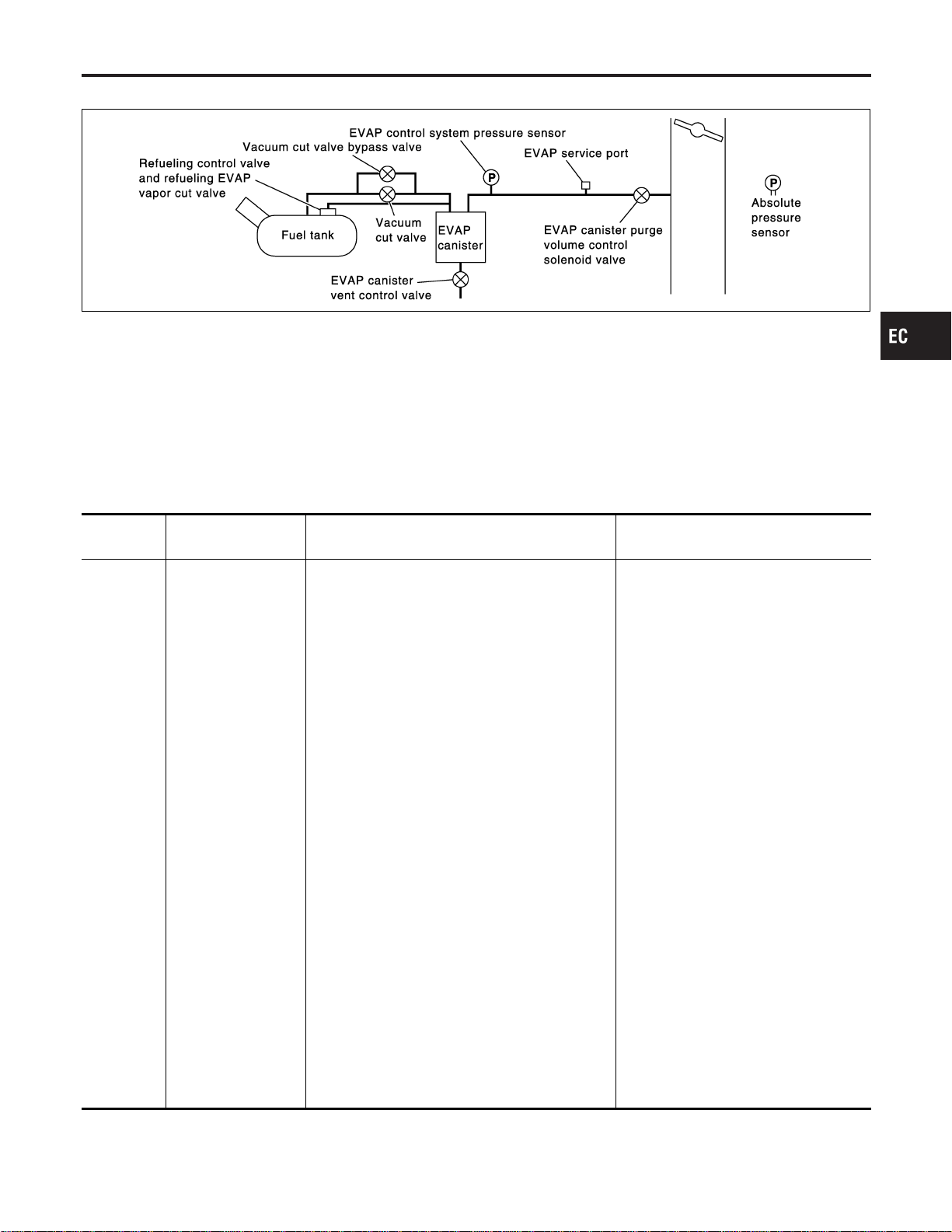
On Board Diagnosis Logic
NFEC1479
SEC936C
This diagnosis detects very small leaks in the EVAP line between fuel tank and EVAP canister purge volume
control solenoid valve, using of vapor pressure in the fuel tank.
The EVAP canister vent control valve is closed to shut the EVAP purge line. The vacuum cut valve bypass
valve will then be opened to clear the line between the fuel tank and the EVAP canister purge volume con-
trol solenoid valve. The EVAP control system pressure sensor can now monitor the pressure inside the fuel
tank. If pressure increases, the ECM will check for leaks in the line between the vacuum cut valve and EVAP
canister purge volume control solenoid valve.
If ECM judges a leak which corresponds to a very small leak, the very small leak P1456 will be detected.
If ECM judges a leak equivalent to a small leak, EVAP small leak P1442 will be detected.
If ECM judges there are no leaks, the diagnosis will be OK.
DTC No.
Trouble diagnosis
name
DTC Detecting Condition Possible Cause
P1456
1456
Evaporative emission
control system very
small leak (positive
pressure check)
I EVAP system has a very small leak.
I EVAP system does not operate properly.
I Incorrect fuel tank vacuum relief valve
I Incorrect fuel filler cap used
I Fuel filler cap remains open or fails to
close.
I Foreign matter caught in fuel filler cap
I Leak is in line between intake mani-
fold and EVAP canister purge volume
control solenoid valve.
I Foreign matter caught in EVAP canis-
ter vent control valve
I EVAP canister or fuel tank leaks
I EVAP purge line (Pipe and rubber
tube) leaks
I EVAP purge line rubber tube bent
I Blocked or bent rubber tube to EVAP
control system pressure sensor
I Loose or disconnected rubber tube
I EVAP canister vent control valve and
the circuit
I EVAP canister purge volume control
solenoid valve and the circuit
I Fuel tank temperature sensor
I O-ring of EVAP canister vent control
valve is missing or damaged.
I Water separator
I EVAP canister saturated with water
I EVAP control system pressure sensor
I Refueling control valve
I ORVR system leaks
I Fuel level sensor and the circuit
I Foreign matter caught in EVAP canis-
ter purge volume control solenoid
valve
CAUTION:
I Use only a genuine NISSAN fuel filler cap as a replacement. If an incorrect fuel filler cap is used,
the MIL may come on.
GI
MA
EM
LC
FE
CL
MT
AT
AX
SU
BR
ST
RS
BT
HA
SC
EL
IDX
DTC P1456 EVAP CONTROL SYSTEM
On Board Diagnosis Logic
EC-603
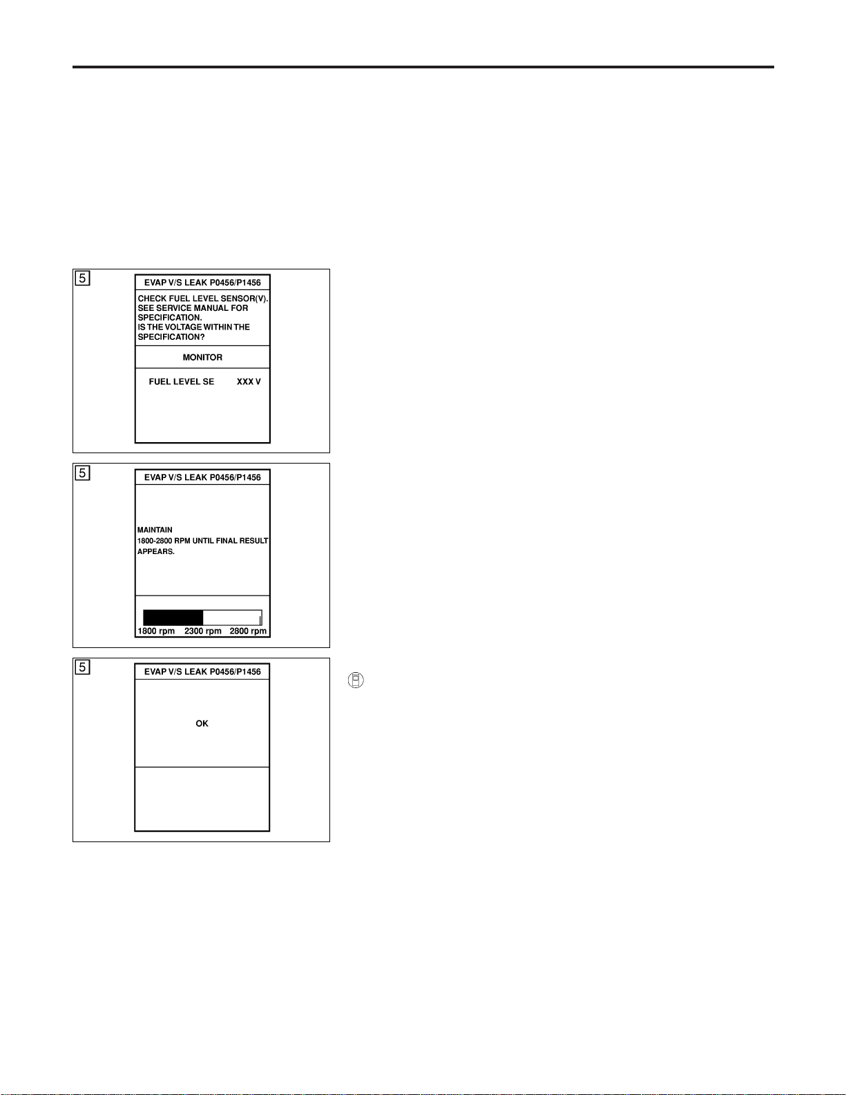
I If the fuel filler cap is not tightened properly, the MIL may come on.
I Use only a genuine NISSAN rubber tube as a replacement.
SEC764C
SEC765C
SEC766C
DTC Confirmation Procedure
NFEC1480
CAUTION:
Never remove fuel filler cap during the DTC confirmation pro-
cedure.
NOTE:
I If DTC P1456 is displayed with P0442, perform TROUBLE
DIAGNOSIS FOR DTC P1456 first.
I If “DTC Confirmation Procedure” has been previously
conducted, always turn ignition switch “OFF” and wait at least
10 seconds before conducting the next test.
I After repair, make sure that the hoses and clips are
installed properly.
TESTING CONDITION:
I Open engine hood before conducting following proce-
dure.
I If any of following conditions are met just before the DTC
confirmation procedure, leave the vehicle for more than 1
hour.
a) Fuel filler cap is removed.
b) Refilled or drained the fuel.
c) EVAP component parts is/are removed.
I Before performing the following procedure, confirm that
battery voltage is more than 11V at idle.
With CONSULT-II
1) Turn ignition switch “ON” and select “DATA MONITOR” mode
with CONSULT-II.
2) Make sure the following conditions are met.
FUEL LEVEL SE: 1.08 - 0.2V
COOLAN TEMP/S: 0 - 32°C (32 - 90°F)
FUEL T/TMP SE: 0 - 35°C (32 - 95°F)
INT A/TEMP SE: More than 0°C (32°F)
If NG, turn ignition switch “OFF” and leave the vehicle in a cool
place (soak the vehicle) or refilling/draining fuel until the out-
put voltage condition of the “FUELLEVELSE” meets within the
range above and leave the vehicle for more than 1 hour. Then
start from step 1).
3) Turn ignition switch “OFF” and wait at least 10 seconds.
4) Turn ignition switch “ON”.
5) Select “EVP V/S LEAK P0456/P1456” of “EVAPORATIVE
SYSTEM” in “DTC WORK SUPPORT” mode with CONSULT-
II.
Follow the instruction displayed.
6) Make sure that “OK” is displayed.
If “NG” is displayed, refer to “Diagnostic Procedure”, EC-606.
DTC P1456 EVAP CONTROL SYSTEM
On Board Diagnosis Logic (Cont’d)
EC-604
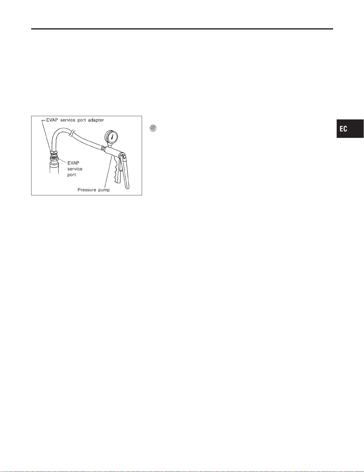
NOTE:
I If the engine speed cannot be maintained within the range
displayed on CONSULT-II screen, go to “Basic
Inspection”, EC-123.
I Make sure that EVAP hoses are connected to EVAP canis-
ter purge volume control solenoid valve properly.
SEF462UA
Overall Function Check
NFEC1481
WITH GST
NFEC1481S01
Use this procedure to check the overall function of the EVAP very
small leak function. During this check, a DTC might not be con-
firmed.
CAUTION:
I Never use compressed air, doing so may damage the
EVAP system.
I Do not start engine.
I Do not exceeded 4.12 kPa (0.042 kg/cm
2
, 0.6 psi).
1) Attach the EVAP service port adapter securely to the EVAP
service port.
2) Set the pressure pump and a hose.
3) Also set a vacuum gauge via 3-way connector and a hose.
4) Turn ignition switch “ON”.
5) Connect GST and select mode 8.
6) Using mode 8 control the EVAP canister vent control valve
(close) and vacuum cut valve bypass valve (open).
7) Apply pressure and make sure the following conditions are
satisfied.
Pressure to be applied: 2.7 kPa (20 mmHg, 0.79 inHg)
Time to be waited after the pressure drawn in to the EVAP
system and the pressure to be dropped: 60 seconds and
the pressure should not be dropped more than 0.4 kPa (3
mmHg, 0.12 inHg)
If NG, go to diagnostic procedure, EC-606.
NOTE:
For more information, refer to GST instruction manual.
GI
MA
EM
LC
FE
CL
MT
AT
AX
SU
BR
ST
RS
BT
HA
SC
EL
IDX
DTC P1456 EVAP CONTROL SYSTEM
DTC Confirmation Procedure (Cont’d)
EC-605
Diagnostic Procedure
NFEC1482
1 CHECK FUEL FILLER CAP DESIGN
1. Turn ignition switch “OFF”.
2. Check for genuine NISSAN fuel filler cap design.
SEF915U
OK or NG
OK © GO TO 2.
NG © Replace with genuine NISSAN fuel filler cap.
2 CHECK FUEL FILLER CAP INSTALLATION
Check that the cap is tightened properly by rotating the cap clockwise.
OK or NG
OK © GO TO 3.
NG © 1. Open fuel filler cap, then clean cap and fuel filler neck threads using air blower.
2. Retighten until ratcheting sound is heard.
3 CHECK FUEL FILLER CAP FUNCTION
Check for air releasing sound while opening the fuel filler cap.
OK or NG
OK © GO TO 5.
NG © GO TO 4.
DTC P1456 EVAP CONTROL SYSTEM
Diagnostic Procedure
EC-606
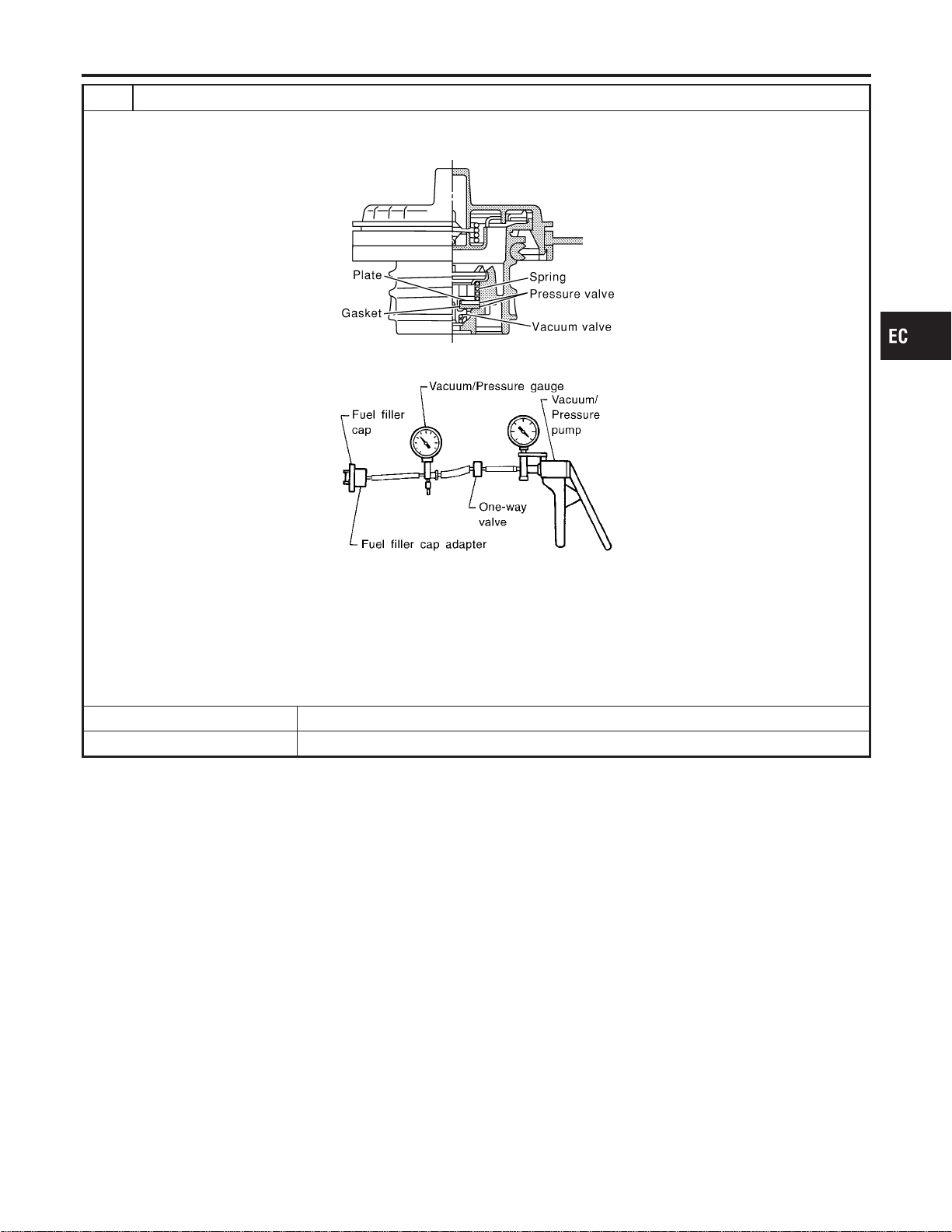
4 CHECK FUEL TANK VACUUM RELIEF VALVE
1. Wipe clean valve housing.
2. Check valve opening pressure and vacuum.
SEF445Y
SEF943S
Pressure:
15.3 - 20.0 kPa (0.156 - 0.204 kg/cm
2
, 2.22 - 2.90 psi)
Vacuum:
−6.0 to −3.3 kPa (−0.061 to −0.034 kg/cm
2
, −0.87 to −0.48 psi)
CAUTION:
Use only a genuine fuel filler cap as a replacement. If an incorrect fuel filler cap is used, the MIL may come on.
OK or NG
OK © GO TO 5.
NG © Replace fuel filler cap with a genuine one.
GI
MA
EM
LC
FE
CL
MT
AT
AX
SU
BR
ST
RS
BT
HA
SC
EL
IDX
DTC P1456 EVAP CONTROL SYSTEM
Diagnostic Procedure (Cont’d)
EC-607

5 INSTALL THE PRESSURE PUMP
To locate the EVAP leak, install EVAP service port adapter and pressure pump to EVAP service port securely.
SEC929C
SEF916U
NOTE:
Improper installation of the EVAP service port adapter to the EVAP service port may cause leaking.
Models with CONSULT-II © GO TO 6.
Models without CON-
SULT-II
© GO TO 7.
DTC P1456 EVAP CONTROL SYSTEM
Diagnostic Procedure (Cont’d)
EC-608
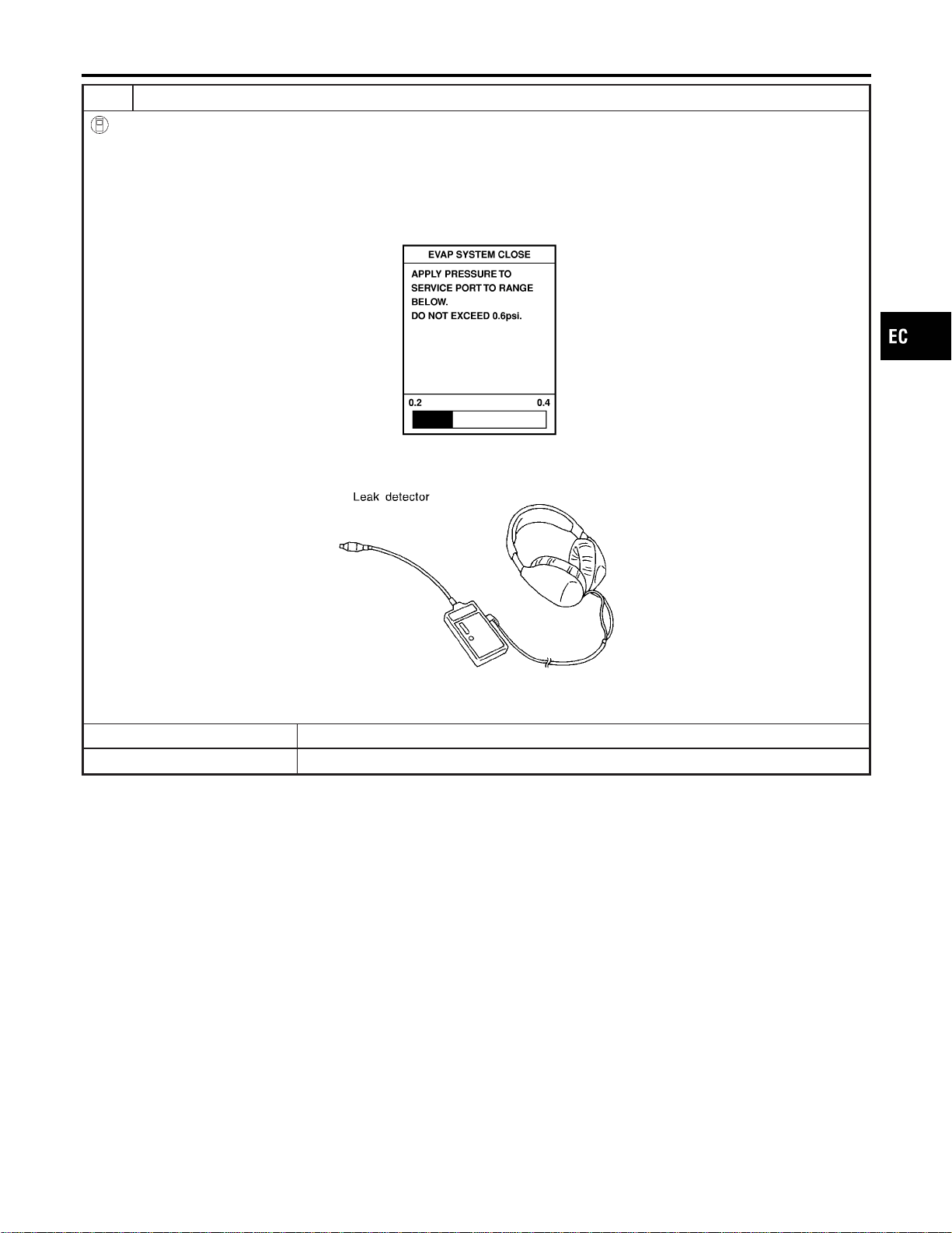
6 CHECK FOR EVAP LEAK
With CONSULT-II
1. Turn ignition switch “ON”.
2. Select “EVAP SYSTEM CLOSE” of “WORK SUPPORT” mode with CONSULT-II.
3. Touch “START” and apply pressure into the EVAP line until the pressure indicator reaches the middle of the bar graph.
NOTE:
I Never use compressed air or a high pressure pump.
I Do not exceed 4.12 kPa (0.042 kg/cm
2
, 0.6 psi) of pressure in the system.
PEF917U
4. Using EVAP leak detector, locate the EVAP leak. For the leak detector, refer to the instruction manual for more details.
Refer to “EVAPORATIVE EMISSION LINE DRAWING”, EC-40.
SEF200U
OK or NG
OK © GO TO 8.
NG © Repair or replace.
GI
MA
EM
LC
FE
CL
MT
AT
AX
SU
BR
ST
RS
BT
HA
SC
EL
IDX
DTC P1456 EVAP CONTROL SYSTEM
Diagnostic Procedure (Cont’d)
EC-609
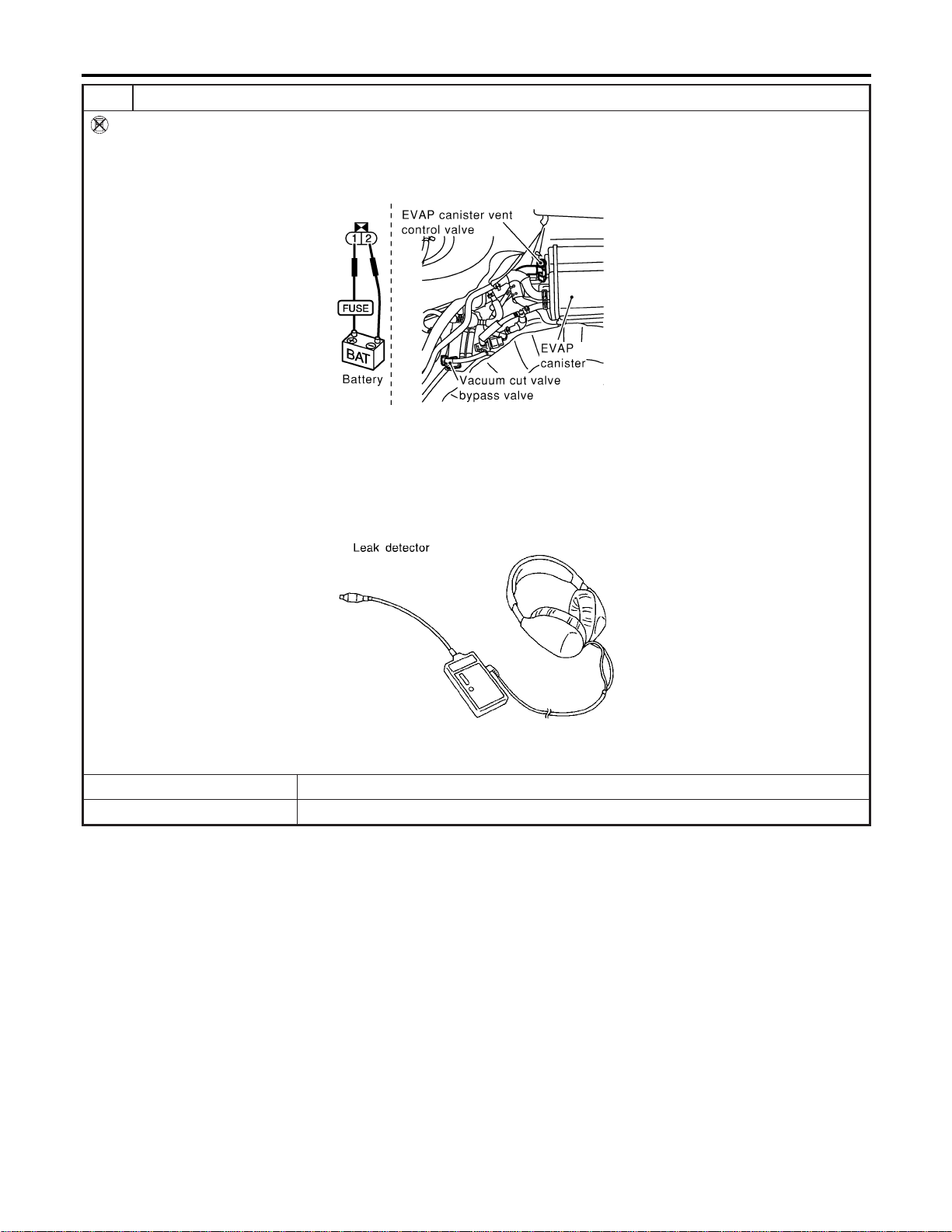
7 CHECK FOR EVAP LEAK
Without CONSULT-II
1. Turn ignition switch “OFF”.
2. Apply 12 volts DC to EVAP canister vent control valve. The valve will close. (Continue to apply 12 volts until the end of
test.)
3. Apply 12 volts DC to vacuum cut valve bypass valve. The valve will open. (Continue to apply 12V until the end of test.)
SEF254X
4. Pressurize the EVAP line using pressure pump with 1.3 to 2.7 kPa (10 to 20 mmHg, 0.39 to 0.79 inHg), then remove
pump and EVAP service port adapter.
NOTE:
I Never use compressed air or a high pressure pump.
I Do not exceed 4.12 kPa (0.042 kg/cm
2
, 0.6 psi) of pressure in the system.
5. Using EVAP leak detector, locate the EVAP leak. For the leak detector, refer to the instruction manual for more details.
Refer to “EVAPORATIVE EMISSION LINE DRAWING”, EC-40.
SEF200U
OK or NG
OK © GO TO 8.
NG © Repair or replace.
DTC P1456 EVAP CONTROL SYSTEM
Diagnostic Procedure (Cont’d)
EC-610
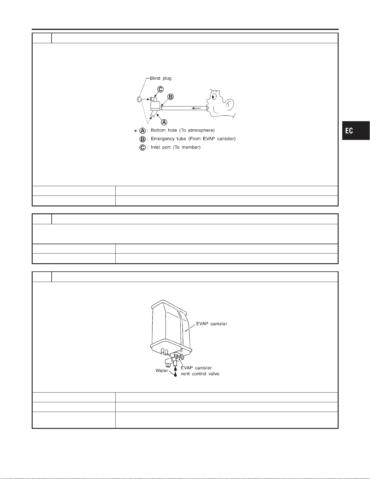
8 CHECK WATER SEPARATOR
1. Check visually for insect nests in the water separator air inlet.
2. Check visually for cracks or flaws in the appearance.
3. Check visually for cracks or flaws in the hose.
4. Check that A and C are not clogged by blowing air into B with A, and then C plugged.
SEF829T
5. In case of NG in items2-4,replace the parts.
NOTE:
Do not disassemble water separator.
OK or NG
OK © GO TO 9.
NG © Replace water separator.
9 CHECK EVAP CANISTER VENT CONTROL VALVE, O-RING AND CIRCUIT
Refer to “DTC Confirmation Procedure”, EC-594.
OK or NG
OK © GO TO 10.
NG © Repair or replace EVAP canister vent control valve and O-ring or harness/connector.
10 CHECK IF EVAP CANISTER SATURATED WITH WATER
1. Remove EVAP canister with EVAP canister vent control valve attached.
2. Does water drain from the EVAP canister?
SEF596U
YesorNo
Yes © GO TO 11.
No (With CONSULT-II) © GO TO 13.
No (Without CONSULT-
II)
© GO TO 14.
GI
MA
EM
LC
FE
CL
MT
AT
AX
SU
BR
ST
RS
BT
HA
SC
EL
IDX
DTC P1456 EVAP CONTROL SYSTEM
Diagnostic Procedure (Cont’d)
EC-611
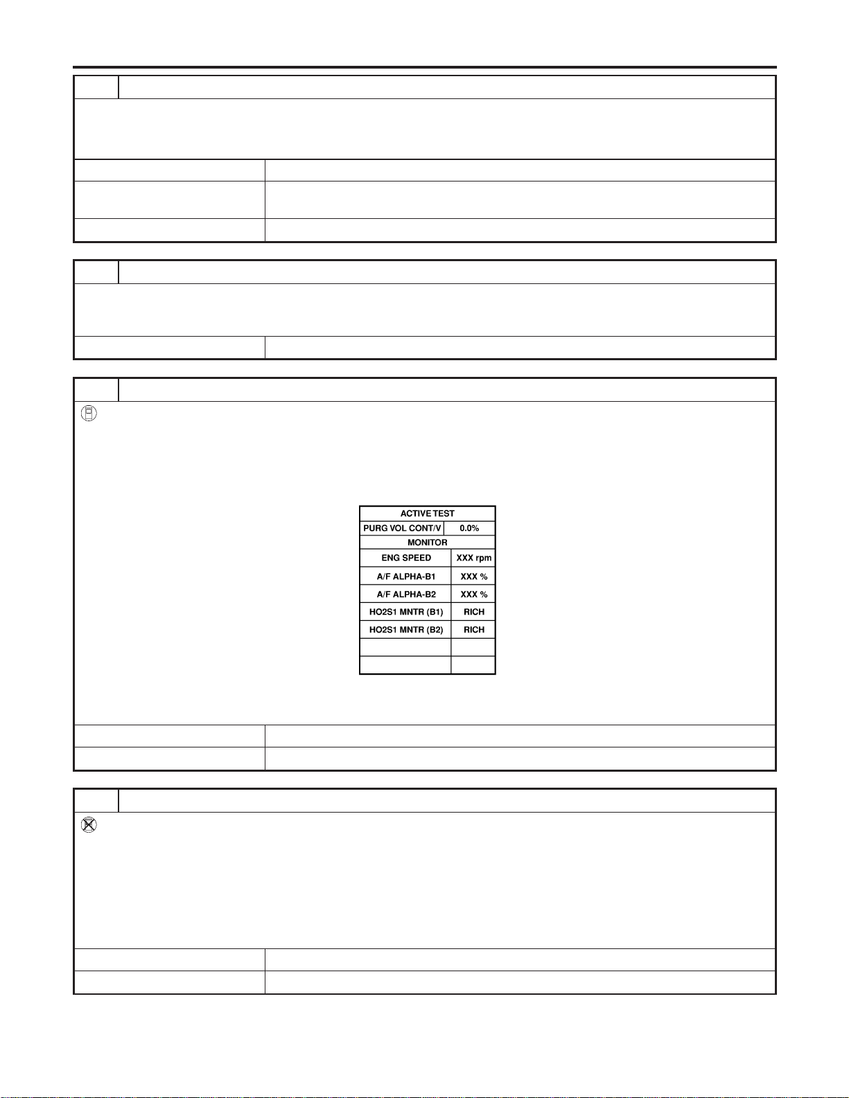
11 CHECK EVAP CANISTER
Weigh the EVAP canister with the EVAP canister vent control valve attached.
The weight should be less than 1.8 kg (4.0 lb).
OK or NG
OK (With CONSULT-II) © GO TO 13.
OK (Without CONSULT-
II)
© GO TO 14.
NG © GO TO 12.
12 DETECT MALFUNCTIONING PART
Check the following.
I EVAP canister for damage
I EVAP hose between EVAP canister and water separator for clogging or poor connection
© Repair hose or replace EVAP canister.
13 CHECK EVAP CANISTER PURGE VOLUME CONTROL SOLENOID VALVE OPERATION
With CONSULT-II
1. Disconnect vacuum hose to EVAP canister purge volume control solenoid valve at EVAP service port.
2. Start engine.
3. Perform “PURG VOL CONT/V” in “ACTIVE TEST” mode.
4. Touch “Qu” on CONSULT-II screen to increase “PURG VOL CONT/V” opening to 100.0%.
5. Check vacuum hose for vacuum when revving engine up to 2,000 rpm.
SEC142D
Vacuum should exist.
OK or NG
OK © GO TO 16.
NG © GO TO 15.
14 CHECK EVAP CANISTER PURGE VOLUME CONTROL SOLENOID VALVE OPERATION
Without CONSULT-II
1. Start engine and warm it up to normal operating temperature.
2. Stop engine.
3. Disconnect vacuum hose to EVAP canister purge volume control solenoid valve at EVAP service port.
4. Start engine and let it idle for at least 80 seconds.
5. Check vacuum hose for vacuum when revving engine up to 2,000 rpm.
Vacuum should exist.
OK or NG
OK © GO TO 17.
NG © GO TO 15.
DTC P1456 EVAP CONTROL SYSTEM
Diagnostic Procedure (Cont’d)
EC-612
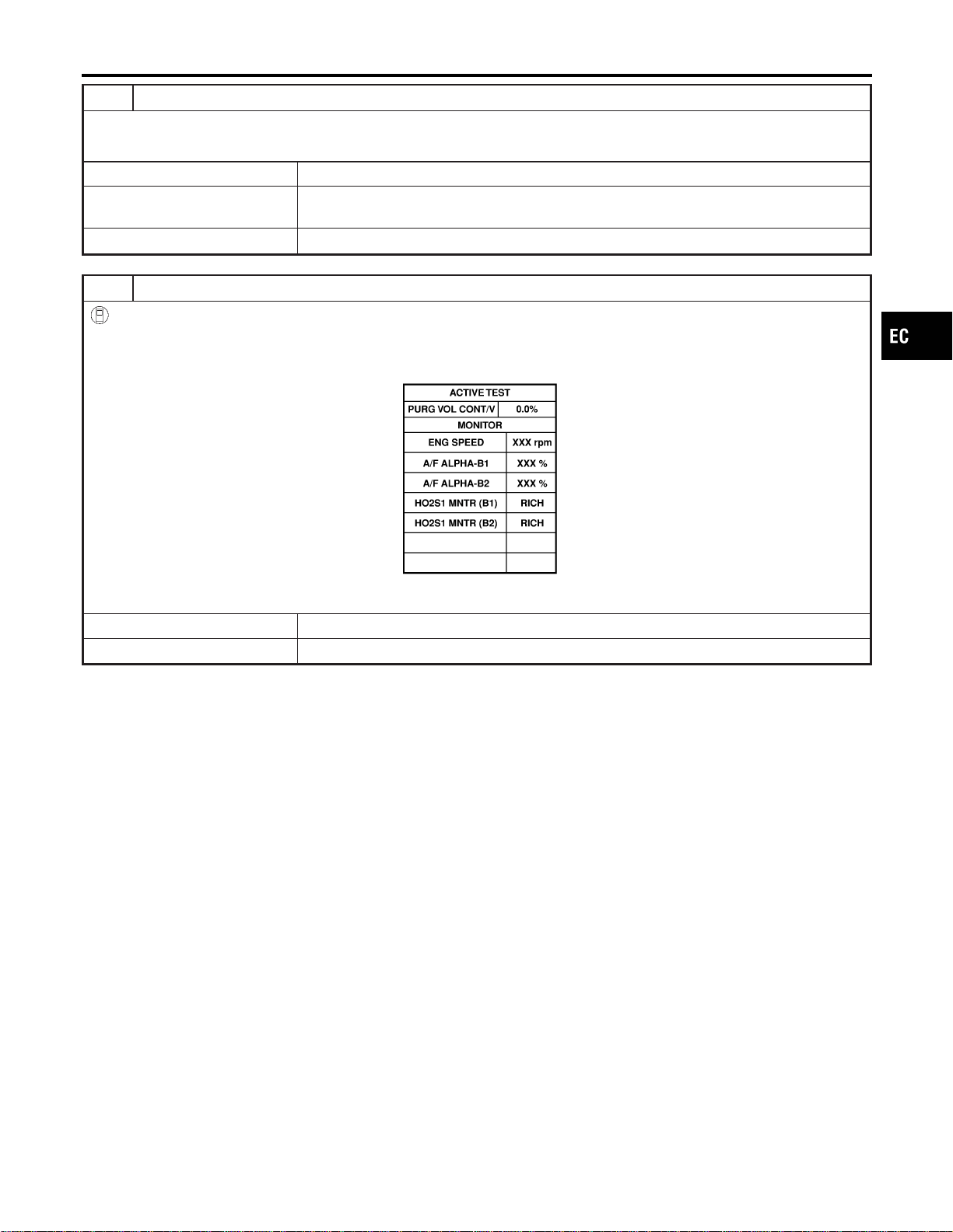
15 CHECK VACUUM HOSE
Check vacuum hoses for clogging or disconnection. Refer to “Vacuum Hose Drawing”, EC-30.
OK or NG
OK (With CONSULT-II) © GO TO 16.
OK (Without CONSULT-
II)
© GO TO 17.
NG © Repair or reconnect the hose.
16 CHECK EVAP CANISTER PURGE VOLUME CONTROL SOLENOID VALVE
With CONSULT-II
1. Start engine.
2. Perform “PURG VOL CONT/V” in “ACTIVE TEST” mode with CONSULT-II. Check that engine speed varies according
to the valve opening.
SEC142D
OK or NG
OK © GO TO 18.
NG © GO TO 17.
GI
MA
EM
LC
FE
CL
MT
AT
AX
SU
BR
ST
RS
BT
HA
SC
EL
IDX
DTC P1456 EVAP CONTROL SYSTEM
Diagnostic Procedure (Cont’d)
EC-613
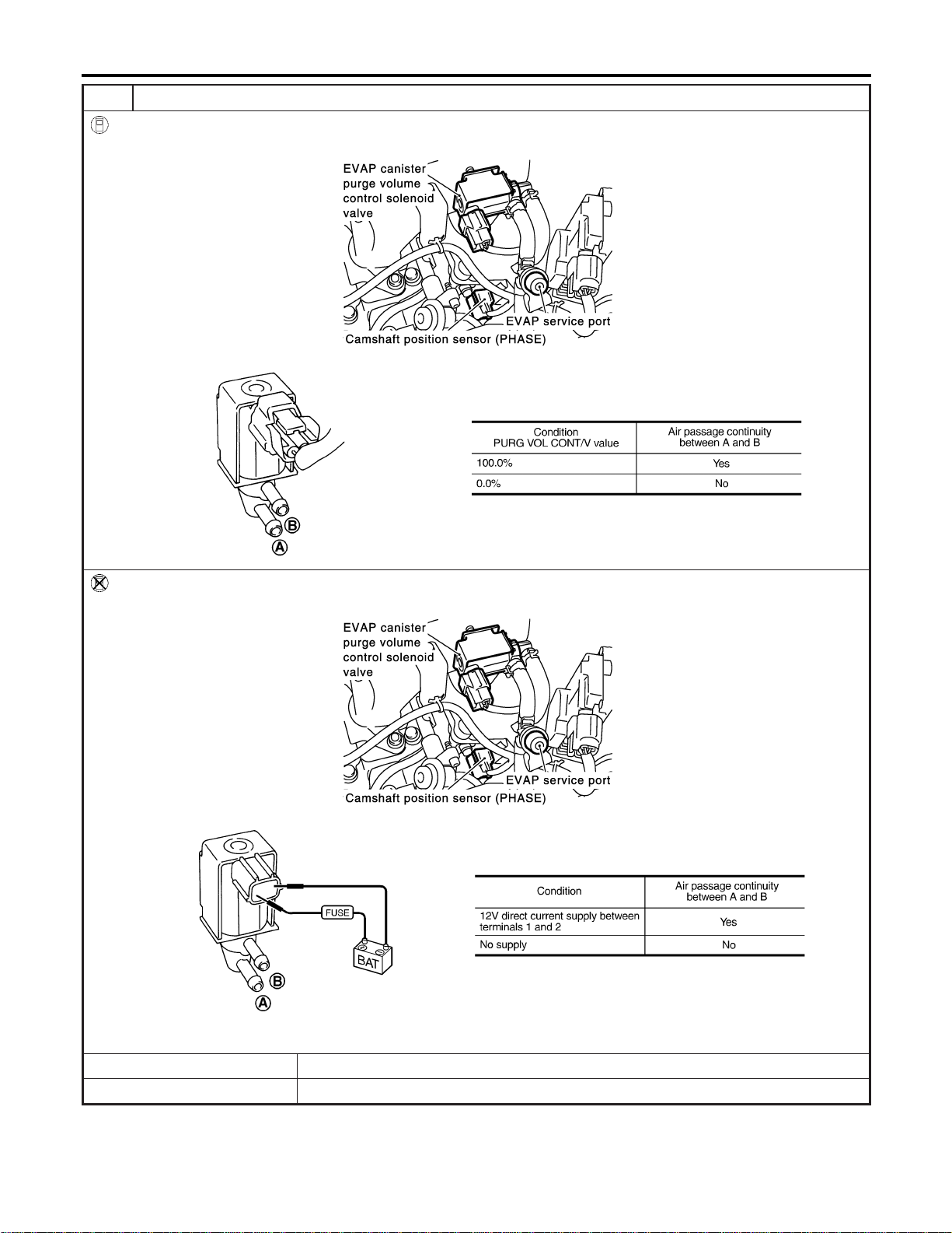
17 CHECK EVAP CANISTER PURGE VOLUME CONTROL SOLENOID VALVE
With CONSULT-II
Check air passage continuity of EVAP canister purge volume control solenoid valve under the following conditions.
SEC929C
SEF334X
Without CONSULT-II
Check air passage continuity of EVAP canister purge volume control solenoid valve under the following conditions.
SEC929C
SEF335X
OK or NG
OK © GO TO 18.
NG © Replace EVAP canister purge volume control solenoid valve.
DTC P1456 EVAP CONTROL SYSTEM
Diagnostic Procedure (Cont’d)
EC-614
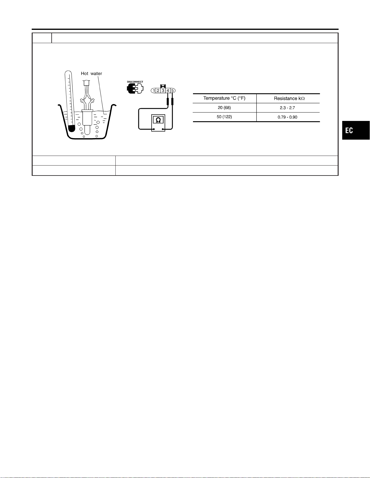
18 CHECK FUEL TANK TEMPERATURE SENSOR
1. Remove fuel level sensor unit.
2. Check resistance between fuel level sensor unit and fuel pump terminals 4 and 5 by heating with hot water or heat gun
as shown in the figure.
SEF587X
OK or NG
OK © GO TO 19.
NG © Replace fuel level sensor unit.
GI
MA
EM
LC
FE
CL
MT
AT
AX
SU
BR
ST
RS
BT
HA
SC
EL
IDX
DTC P1456 EVAP CONTROL SYSTEM
Diagnostic Procedure (Cont’d)
EC-615
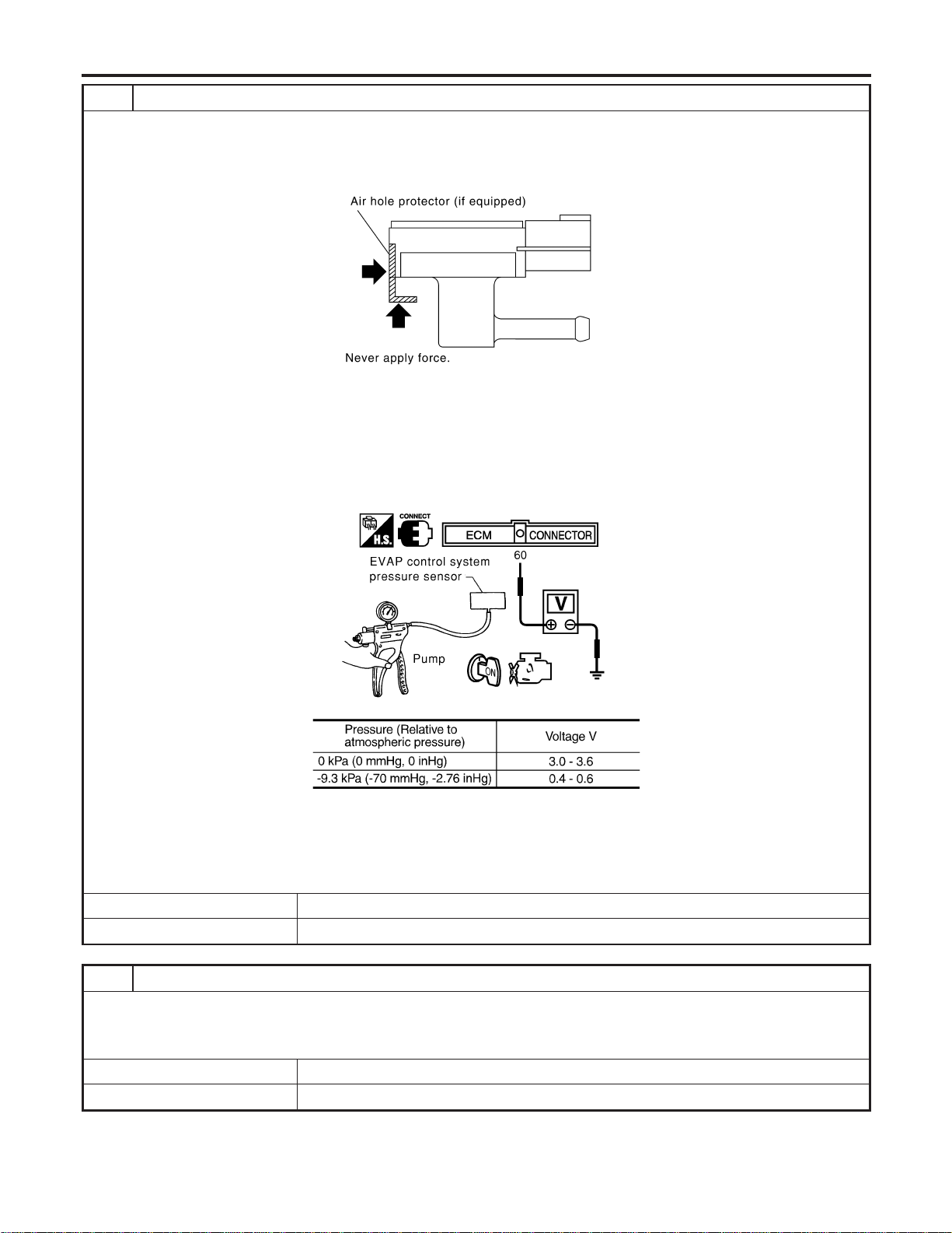
19 CHECK EVAP CONTROL SYSTEM PRESSURE SENSOR
1. Remove EVAP control system pressure sensor with its harness connector connected.
CAUTION:
Never apply force to the air hole protector of the sensor if equipped.
SEF799W
2. Remove hose from EVAP control system pressure sensor.
3. Turn ignition switch “ON”.
4. Use pump to apply vacuum and pressure to EVAP control system pressure sensor as shown in figure.
CAUTION:
I Always calibrate the vacuum pump gauge when using it.
I Do not apply below −20 kPa (−150 mmHg, −5.91 inHg) or over 20 kPa (150 mmHg, 5.91 inHg) of pressure.
5. Check input voltage between ECM terminal 60 and ground.
SEC908C
MTBL1159
CAUTION:
Discard and EVAP control system pressure sensor which has been dropped from a height of more than 0.5 m
(19.7 in) onto a hard surface such as a concrete floor; use a new one.
OK or NG
OK © GO TO 20.
NG © Replace EVAP control system pressure sensor.
20 CHECK EVAP PURGE LINE
Check EVAP purge line (pipe, rubber tube, fuel tank and EVAP canister) for cracks or improper connection.
Refer to “Evaporative Emission System”, EC-36.
OK or NG
OK © GO TO 21.
NG © Repair or reconnect the hose.
DTC P1456 EVAP CONTROL SYSTEM
Diagnostic Procedure (Cont’d)
EC-616
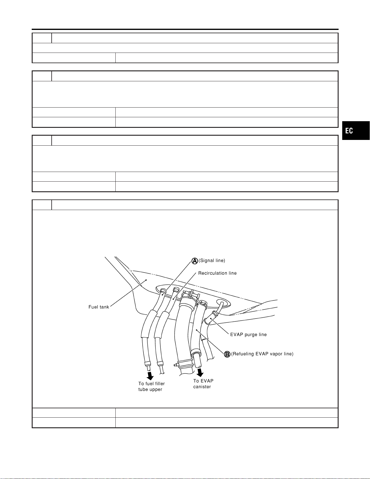
21 CLEAN EVAP PURGE LINE
Clean EVAP purge line (pipe and rubber tube) using air blower.
© GO TO 22.
22 CHECK REFUELING EVAP VAPOR LINE
Check refueling EVAP vapor line between EVAP canister and fuel tank for clogging, kink, looseness and improper connec-
tion. For location, refer to “EVAPORATIVE EMISSION LINE DRAWING”, EC-40.
OK or NG
OK © GO TO 23.
NG © Repair or replace hoses and tubes.
23 CHECK SIGNAL LINE AND RECIRCULATION LINE
Check signal line and recirculation line between filler neck tube and fuel tank for clogging, kink, cracks, looseness and
improper connection.
OK or NG
OK © GO TO 24.
NG © Repair or replace hoses, tubes or filler neck tube.
24 CHECK REFUELING CONTROL VALVE
1. Remove fuel filler cap.
2. Check air continuity between hose ends A and B.
Blow air into hose end B. Air should flow freely into the fuel tank.
3. Blow air into hose end A and check that there is no leakage.
4. Apply pressure to both hose ends A and B [20 kPa (150 mmHg, 5.91 inHg)] using a pressure pump and a suitable
3-way connector. Check that there is no leakage.
SEF830X
OK or NG
OK © GO TO 25.
NG © Replace or refueling control valve with fuel tank.
GI
MA
EM
LC
FE
CL
MT
AT
AX
SU
BR
ST
RS
BT
HA
SC
EL
IDX
DTC P1456 EVAP CONTROL SYSTEM
Diagnostic Procedure (Cont’d)
EC-617
25 CHECK FUEL LEVEL SENSOR
Refer to EL-129, “Fuel Level Sensor Unit Check”.
OK or NG
OK © GO TO 26.
NG © Replace fuel level sensor unit.
26 CHECK INTERMITTENT INCIDENT
Refer to “TROUBLE DIAGNOSIS FOR INTERMITTENT INCIDENT”, EC-156.
© INSPECTION END
DTC P1456 EVAP CONTROL SYSTEM
Diagnostic Procedure (Cont’d)
EC-618
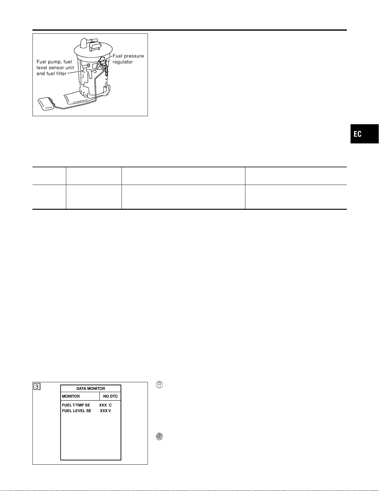
SEC088D
Component Description
NFEC1111
The fuel level sensor is mounted in the fuel level sensor unit. The
sensor detects a fuel level in the fuel tank and transmits a signal
to the ECM.
It consists of two parts, one is mechanical float and the other side
is variable resistor. Fuel level sensor output voltage changes
depending on the movement of the fuel mechanical float.
On Board Diagnostic Logic
NFEC1112
ECM receives two signals from the fuel level sensor.
One is fuel level sensor power supply circuit, and the other is fuel
level sensor ground circuit.
This diagnosis indicates the latter to detect open circuit malfunc-
tion.
DTC No.
Trouble diagnosis
name
DTC Detecting Condition Possible Cause
P1464
1464
Fuel level sensor cir-
cuit ground signal
A high voltage from the sensor is sent to ECM. I Fuel level sensor circuit
(The fuel level sensor circuit is open
or shorted.)
DTC Confirmation Procedure
NFEC1113
NOTE:
If “DTC Confirmation Procedure” has been previously conducted,
always turn ignition switch “OFF” and wait at least 10 seconds
before conducting the next test.
SEF195Y
WITH CONSULT-II
NFEC1113S01
1) Turn ignition switch “ON”.
2) Select “DATA MONITOR” mode with CONSULT-II.
3) Wait at least 5 seconds.
4) If 1st trip DTC is detected, go to “Diagnostic Procedure”,
EC-621.
WITH GST
NFEC1113S02
Follow the procedure “WITH CONSULT-II” above.
GI
MA
EM
LC
FE
CL
MT
AT
AX
SU
BR
ST
RS
BT
HA
SC
EL
IDX
DTC P1464 FUEL LEVEL SENSOR
Component Description
EC-619
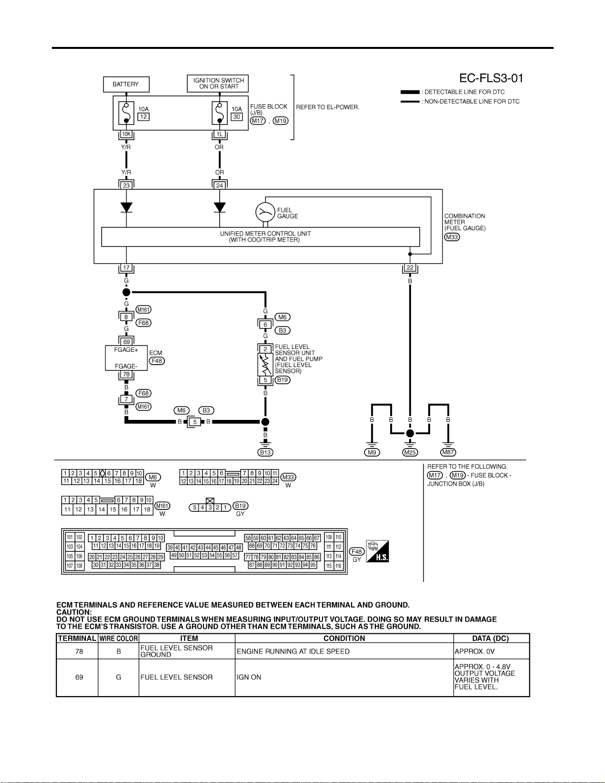
Wiring Diagram
NFEC1114
MEC508D
SEF711YB
DTC P1464 FUEL LEVEL SENSOR
Wiring Diagram
EC-620
Diagnostic Procedure
=NFEC1115
1 CHECK FUEL LEVEL SENSOR GROUND CIRCUIT FOR OPEN AND SHORT
1. Turn ignition switch “OFF”.
2. Disconnect ECM harness connector.
3. Check harness continuity between ECM terminal 78 and body ground. Refer to Wiring Diagram.
Continuity should exist.
4. Also check harness for short to power.
OK or NG
OK © GO TO 3.
NG © GO TO 2.
2 DETECT MALFUNCTIONING PART
1. Check the following.
I Harness connectors F68, M161
I Harness connectors M6, B3
I Harness for open between ECM and body ground
© Replace open circuit or short to power in harness or connectors.
3 CHECK FUEL LEVEL SENSOR
Refer to EL-129, “Fuel Level Sensor Unit Check”.
OK or NG
OK © GO TO 4.
NG © Replace fuel level sensor unit.
4 CHECK INTERMITTENT INCIDENT
Refer to “TROUBLE DIAGNOSIS FOR INTERMITTENT INCIDENT”, EC-156.
OK or NG
© INSPECTION END
GI
MA
EM
LC
FE
CL
MT
AT
AX
SU
BR
ST
RS
BT
HA
SC
EL
IDX
DTC P1464 FUEL LEVEL SENSOR
Diagnostic Procedure
EC-621
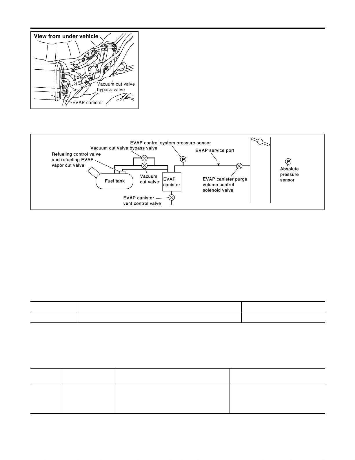
SEF278X
Description
=NFEC1116
COMPONENT DESCRIPTION
NFEC1116S01
The vacuum cut valve and vacuum cut valve bypass valve are
installed in parallel on the EVAP purge line between the fuel tank
and the EVAP canister.
The vacuum cut valve prevents the intake manifold vacuum from
being applied to the fuel tank.
The vacuum cut valve bypass valve is a solenoid type valve and
generally remains closed. It opens only for on board diagnosis.
The vacuum cut valve bypass valve responds to signals from the
ECM. When the ECM sends an ON (ground) signal, the valve is
opened. The vacuum cut valve is then bypassed to apply intake
manifold vacuum to the fuel tank.
EVAPORATIVE EMISSION SYSTEM DIAGRAM
NFEC1116S02
SEC936C
CONSULT-II Reference Value in Data Monitor
Mode
NFEC1117
Specification data are reference values.
MONITOR ITEM CONDITION SPECIFICATION
VC/V BYPASS/V I Ignition switch: ON OFF
On Board Diagnosis Logic
NFEC1119
DTC No.
Trouble diagnosis
name
DTC Detecting Condition Possible Cause
P1490
1490
Vacuum cut valve
bypass valve circuit
An improper voltage signal is sent to ECM through
vacuum cut valve bypass valve.
I Harness or connectors
(The vacuum cut valve bypass valve
circuit is open or shorted.)
I Vacuum cut valve bypass valve
DTC P1490 VACUUM CUT VALVE BYPASS VALVE
Description
EC-622
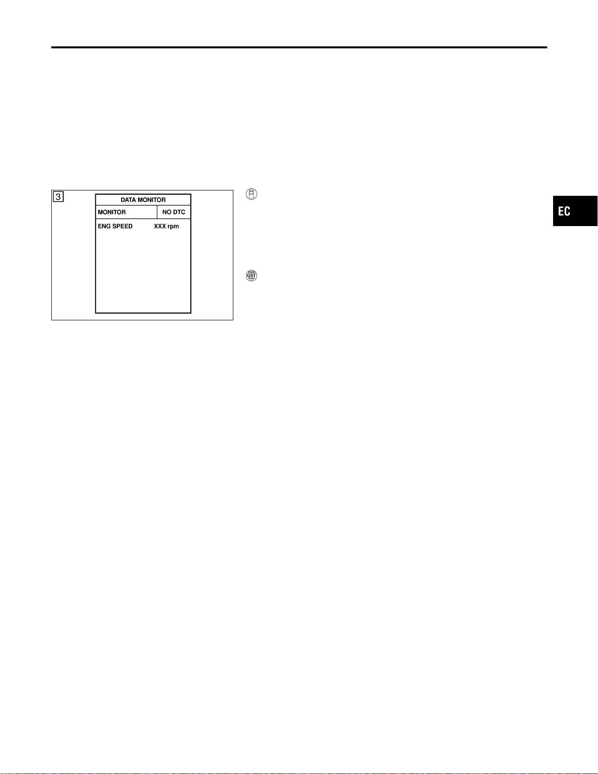
DTC Confirmation Procedure
NFEC1120
NOTE:
If “DTC Confirmation Procedure” has been previously conducted,
always turn ignition switch “OFF” and wait at least 10 seconds
before conducting the next test.
TESTING CONDITION:
Before performing the following procedure, confirm that bat-
tery voltage is more than 11V at idle speed.
SEF058Y
WITH CONSULT-II
NFEC1120S01
1) Turn ignition switch “ON”.
2) Select “DATA MONITOR” mode with CONSULT-II.
3) Start engine and wait at least 5 seconds.
4) If 1st trip DTC is detected, go to “Diagnostic Procedure”,
EC-625.
WITH GST
NFEC1120S02
Follow the procedure “WITH CONSULT-II” above.
GI
MA
EM
LC
FE
CL
MT
AT
AX
SU
BR
ST
RS
BT
HA
SC
EL
IDX
DTC P1490 VACUUM CUT VALVE BYPASS VALVE
DTC Confirmation Procedure
EC-623
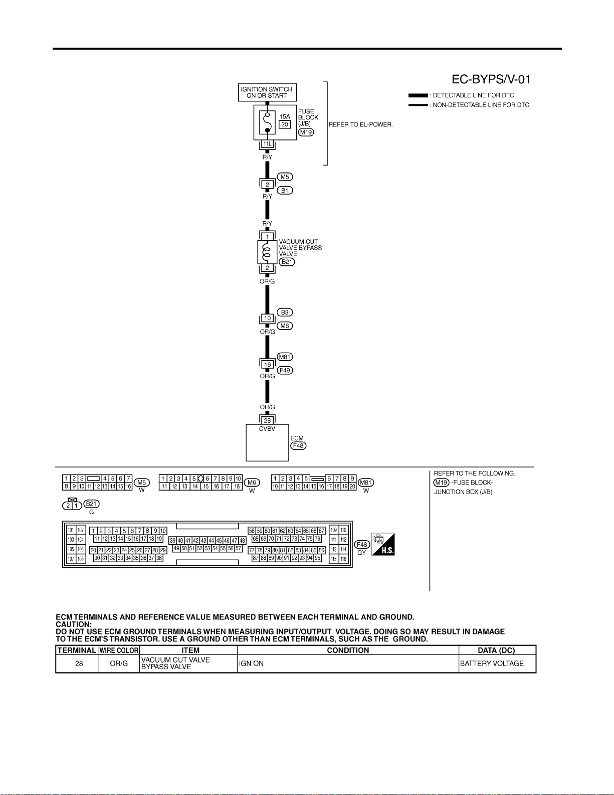
Wiring Diagram
NFEC1121
MEC510D
SEF634XD
DTC P1490 VACUUM CUT VALVE BYPASS VALVE
Wiring Diagram
EC-624
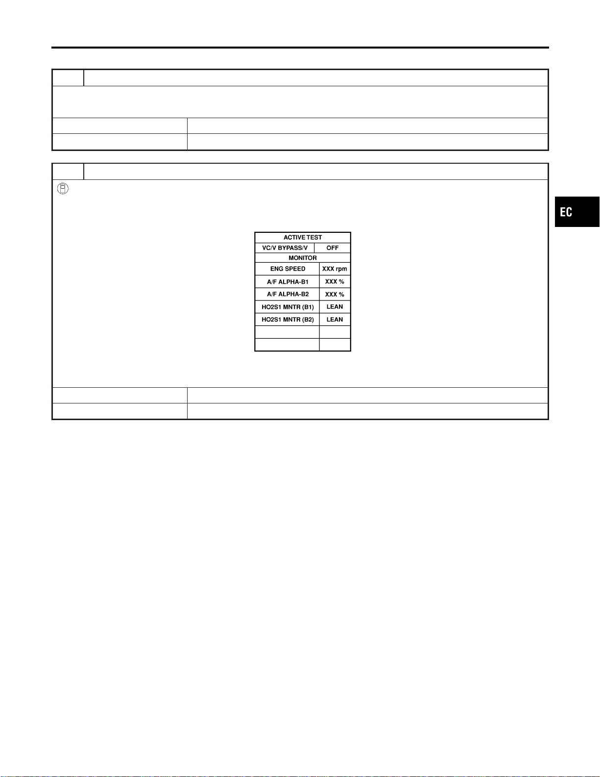
Diagnostic Procedure
NFEC1122
1 INSPECTION START
Do you have CONSULT-II?
YesorNo
Yes © GO TO 2.
No © GO TO 3.
2 CHECK VACUUM CUT VALVE BYPASS VALVE CIRCUIT
With CONSULT-II
1. Turn ignition switch “OFF” and then “ON”.
2. Select “VC/V BYPASS/V” in “ACTIVE TEST” mode with CONSULT-II.
3. Touch “ON/OFF” on CONSULT-II screen.
PBIB0157E
4. Make sure that clicking sound is heard from the vacuum cut valve bypass valve.
OK or NG
OK © GO TO 7.
NG © GO TO 3.
GI
MA
EM
LC
FE
CL
MT
AT
AX
SU
BR
ST
RS
BT
HA
SC
EL
IDX
DTC P1490 VACUUM CUT VALVE BYPASS VALVE
Diagnostic Procedure
EC-625
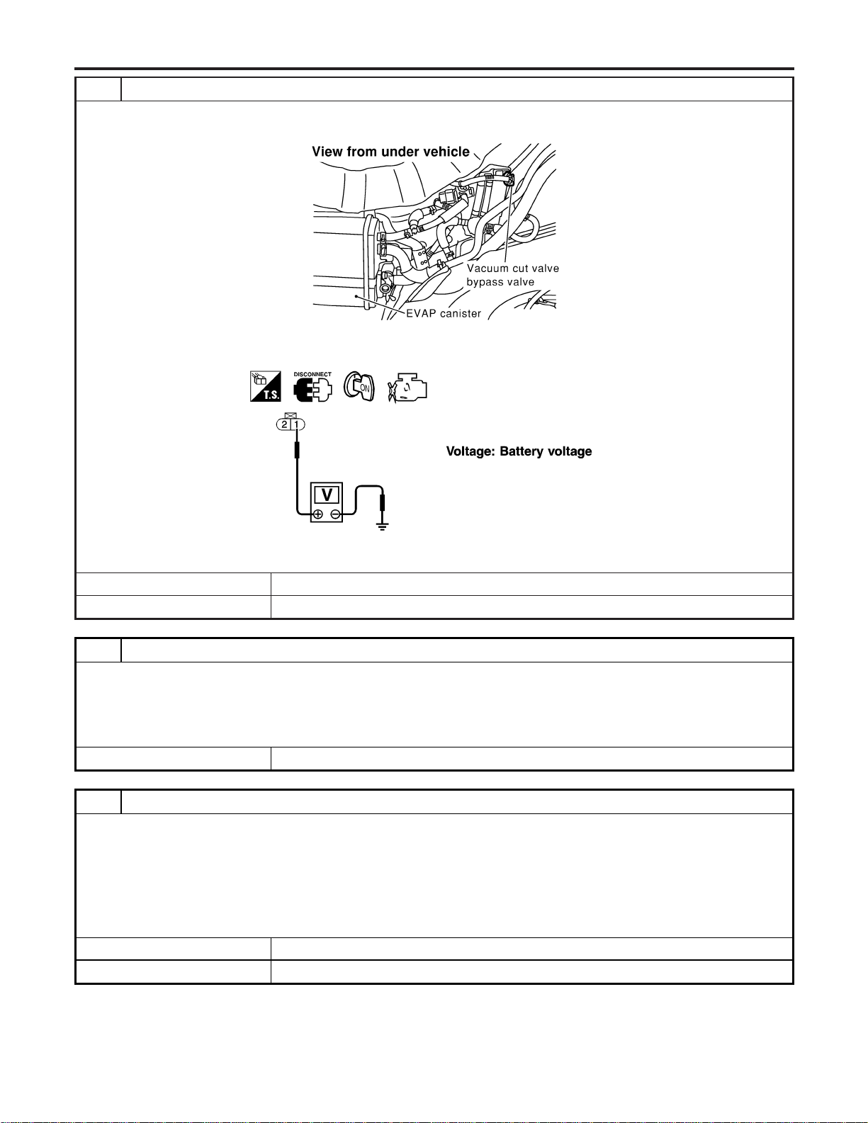
3 CHECK VACUUM CUT VALVE BYPASS VALUE POWER SUPPLY CIRCUIT
1. Turn ignition switch “OFF”.
2. Disconnect vacuum cut valve bypass valve harness connector.
SEF278X
3. Turn ignition switch “ON”.
4. Check voltage between vacuum cut valve bypass valve terminal 1 and ground with CONSULT-II or tester.
SEF356X
OK or NG
OK © GO TO 5.
NG © GO TO 4.
4 DETECT MALFUNCTIONING PART
Check the following.
I Harness connectors M5, B1
I Fuse block (J/B) connector M19
I 15A fuse
I Harness for open or short between vacuum cut valve bypass valve and fuse
© Repair harness or connectors.
5 CHECK VACUUM CUT VALVE BYPASS VALVE OUTPUT SIGNAL CIRCUIT FOR OPEN AND SHORT
1. Turn ignition switch “OFF”.
2. Disconnect ECM harness connector.
3. Check harness continuity between ECM terminal 28 and vacuum cut valve bypass valve terminal 2. Refer to Wiring
Diagram.
Continuity should exist.
4. Also check harness for short to ground and short to power.
OK or NG
OK © GO TO 7.
NG © GO TO 6.
DTC P1490 VACUUM CUT VALVE BYPASS VALVE
Diagnostic Procedure (Cont’d)
EC-626
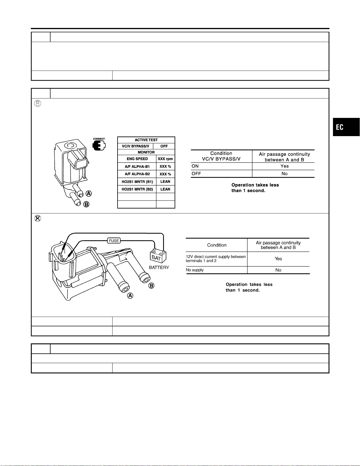
6 DETECT MALFUNCTIONING PART
Check the following.
I Harness connectors B3, M6
I Harness connectors M81, F49
I Harness for open or short between vacuum cut valve bypass valve and ECM
© Repair open circuit or short to ground or short to power in harness or connectors.
7 CHECK VACUUM CUT VALVE BYPASS VALVE
With CONSULT-II
1. Reconnect harness disconnected connectors.
2. Turn ignition switch ON.
3. Perform “VC/V BYPASS/V” in “ACTIVE TEST” mode.
4. Check air passage continuity and operation delay time under the following conditions.
SEC156D
Without CONSULT-II
Check air passage continuity and operation delay time under the following conditions.
SEF358X
OK or NG
OK © GO TO 8.
NG © Replace vacuum cut valve bypass valve.
8 CHECK INTERMITTENT INCIDENT
Refer to “TROUBLE DIAGNOSIS FOR INTERMITTENT INCIDENT”, EC-156.
© INSPECTION END
GI
MA
EM
LC
FE
CL
MT
AT
AX
SU
BR
ST
RS
BT
HA
SC
EL
IDX
DTC P1490 VACUUM CUT VALVE BYPASS VALVE
Diagnostic Procedure (Cont’d)
EC-627
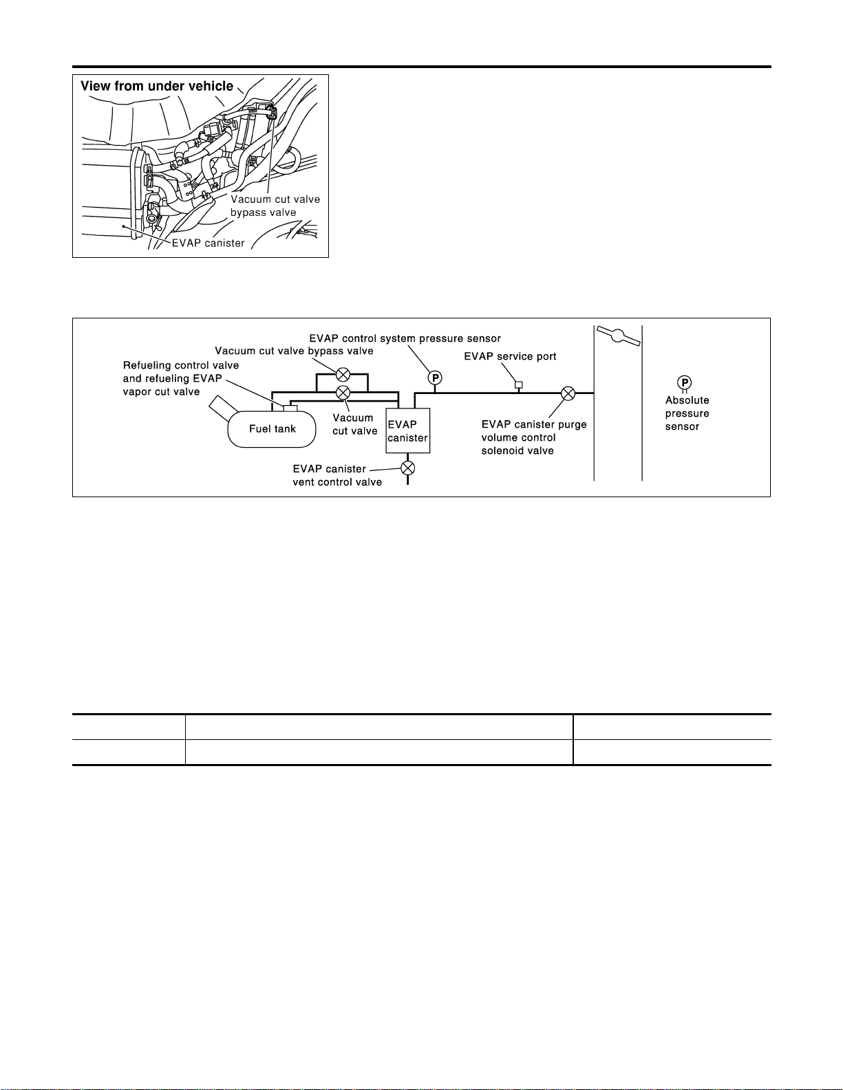
SEF278X
Description
NFEC1123
COMPONENT DESCRIPTION
NFEC1123S01
The vacuum cut valve and vacuum cut valve bypass valve are
installed in parallel on the EVAP purge line between the fuel tank
and the EVAP canister.
The vacuum cut valve prevents the intake manifold vacuum from
being applied to the fuel tank.
The vacuum cut valve bypass valve is a solenoid type valve and
generally remains closed. It opens only for on board diagnosis.
The vacuum cut valve bypass valve responds to signals from the
ECM. When the ECM sends an ON (ground) signal, the valve is
opened. The vacuum cut valve is then bypassed to apply intake
manifold vacuum to the fuel tank.
EVAPORATIVE EMISSION SYSTEM DIAGRAM
NFEC1123S02
SEC936C
CONSULT-II Reference Value in Data Monitor
Mode
NFEC1124
Specification data are reference values.
MONITOR ITEM CONDITION SPECIFICATION
VC/V BYPASS/V I Ignition switch: ON OFF
DTC P1491 VACUUM CUT VALVE BYPASS VALVE
Description
EC-628
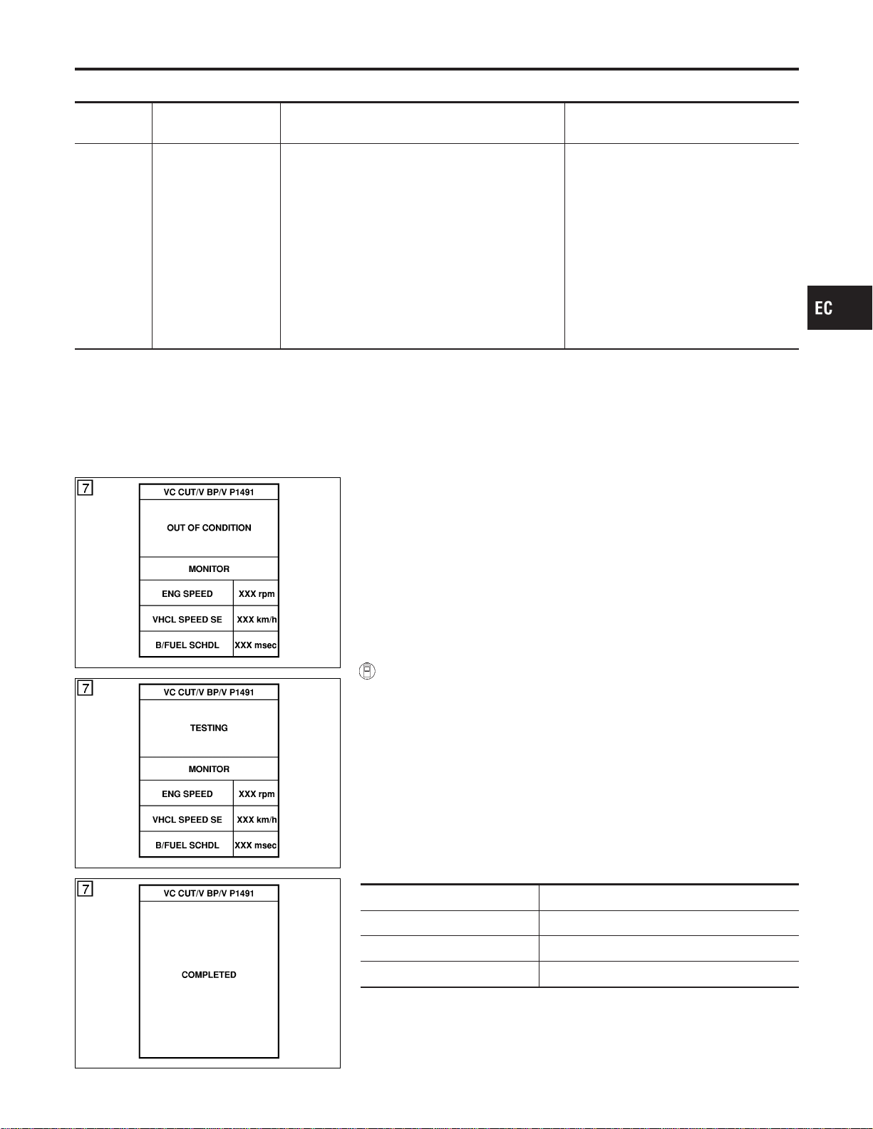
On Board Diagnosis Logic
NFEC1126
DTC No.
Trouble diagnosis
name
DTC Detecting Condition Possible Cause
P1491
1491
Vacuum cut valve
bypass valve
Vacuum cut valve bypass valve does not operate
properly.
I Vacuum cut valve bypass valve
I Vacuum cut valve
I Bypass hoses for clogging
I EVAP control system pressure sensor
and circuit
I EVAP canister vent control valve
I Hose between fuel tank and vacuum
cut valve clogged
I Hose between vacuum cut valve and
EVAP canister clogged
I EVAP canister
I EVAP purge port of fuel tank for clog-
ging
SEF210Y
SEF211Y
SEF239Y
DTC Confirmation Procedure
NFEC1127
CAUTION:
Always drive vehicle at a safe speed.
NOTE:
If “DTC Confirmation Procedure” has been previously conducted,
always turn ignition switch “OFF” and wait at least 10 seconds
before conducting the next test.
TESTING CONDITION:
For best results, perform test at a temperature of 5 to 30°C (41
to 86°F).
WITH CONSULT-II
NFEC1127S01
1) Turn ignition switch “ON”.
2) Start engine and warm it up to normal operating temperature.
3) Turn ignition switch “OFF” and wait at least 10 seconds.
4) Start engine and let it idle for at least 70 seconds.
5) Select “VC CUT/V BP/V P1491” of “EVAPORATIVE SYSTEM”
in “DTC WORK SUPPORT” mode with CONSULT-II.
6) Touch “START”.
7) When the following conditions are met, “TESTING” will be dis-
played on the CONSULT-II screen. Maintain the conditions
continuously until “TESTING” changes to “COMPLETED”. (It
will take at least 30 seconds.)
ENG SPEED Idle speed or more
Selector lever Suitable position
Vehicle speed 35 - 120 km/h (22 - 75 MPH) or more
B/FUEL SCHDL 1.3 - 8.1 msec
If “TESTING” is not displayed after 5 minutes, retry from
step 3.
8) Make sure that “OK” is displayed after touching “SELF-DIAG
GI
MA
EM
LC
FE
CL
MT
AT
AX
SU
BR
ST
RS
BT
HA
SC
EL
IDX
DTC P1491 VACUUM CUT VALVE BYPASS VALVE
On Board Diagnosis Logic
EC-629
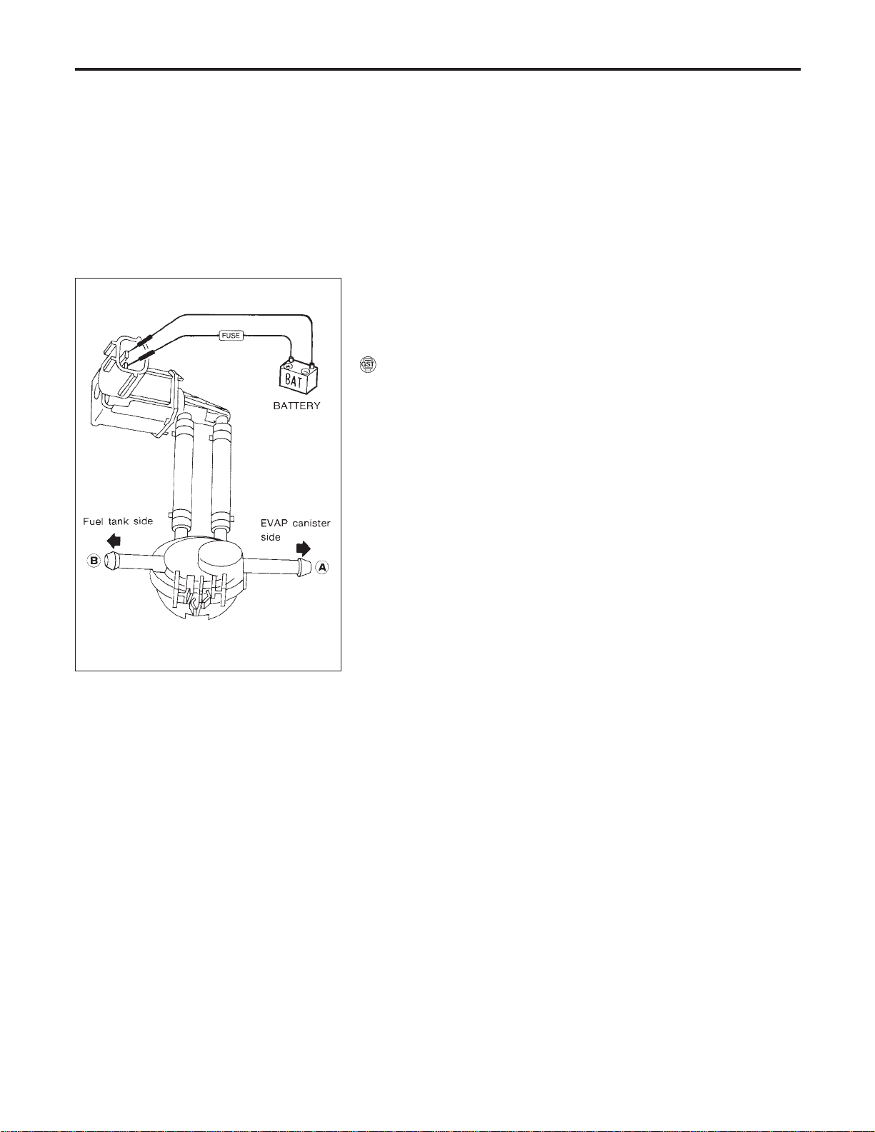
RESULTS”. If “NG” is displayed, refer to “Diagnostic
Procedure”, EC-632.
SEF530Q
Overall Function Check
NFEC1128
Use this procedure to check the overall function of vacuum cut
valve bypass valve. During this check, the 1st trip DTC might not
be confirmed.
WITH GST
NFEC1128S01
1) Remove vacuum cut valve and vacuum cut valve bypass valve
as an assembly.
2) Apply vacuum to port A and check that there is no suction from
port B.
3) Apply vacuum to port B and check that there is suction from
port A.
4) Blow air in port B and check that there is a resistance to flow
out of port A.
5) Supply battery voltage to the terminal.
6) Blow air in port A and check that air flows freely out of port B.
7) Blow air in port B and check that air flows freely out of port A.
8) If NG, go to “Diagnostic Procedure”, EC-632.
DTC P1491 VACUUM CUT VALVE BYPASS VALVE
DTC Confirmation Procedure (Cont’d)
EC-630
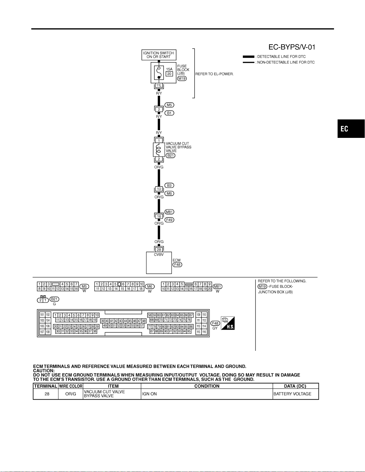
Wiring Diagram
NFEC1129
MEC510D
SEF634XD
GI
MA
EM
LC
FE
CL
MT
AT
AX
SU
BR
ST
RS
BT
HA
SC
EL
IDX
DTC P1491 VACUUM CUT VALVE BYPASS VALVE
Wiring Diagram
EC-631
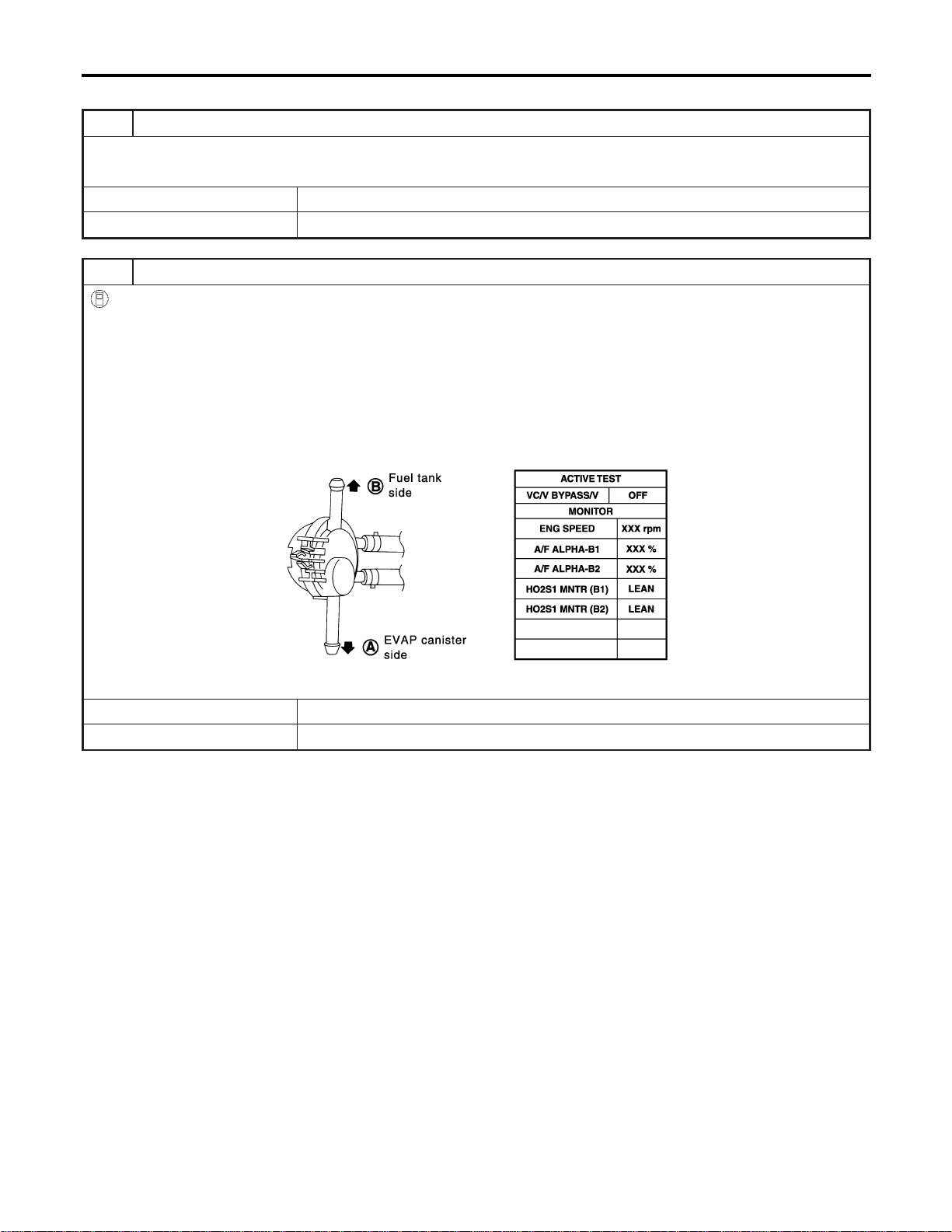
Diagnostic Procedure
NFEC1130
1 INSPECTION START
Do you have CONSULT-II?
YesorNo
Yes © GO TO 2.
No © GO TO 3.
2 CHECK VACUUM CUT VALVE BYPASS VALVE OPERATION
With CONSULT-II
1. Turn ignition switch “OFF”.
2. Remove vacuum cut valve and vacuum cut valve bypass valve as an assembly.
3. Apply vacuum to port A and check that there is no suction from port B.
4. Apply vacuum to port B and check that there is suction from port A.
5. Blow air in port B and check that there is a resistance to flow out of port A.
6. Turn ignition switch “ON”.
7. Select “VC/V BYPASS/V” in “ACTIVE TEST” mode with CONSULT-II and touch “ON”.
8. Blow air in port A and check that air flows freely out of port B.
9. Blow air in port B and check that air flows freely out of port A.
SEC157D
OK or NG
OK © GO TO 4.
NG © GO TO 5.
DTC P1491 VACUUM CUT VALVE BYPASS VALVE
Diagnostic Procedure
EC-632
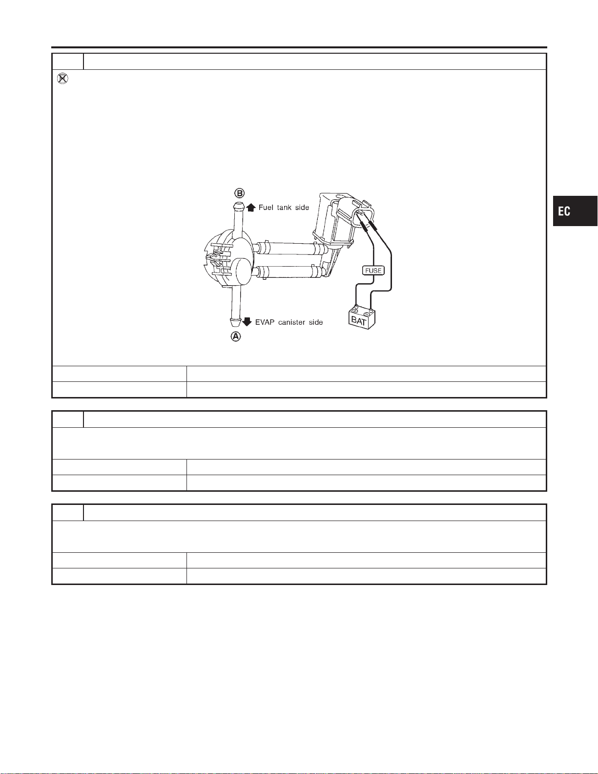
3 CHECK VACUUM CUT VALVE BYPASS VALVE OPERATION
Without CONSULT-II
1. Turn ignition switch “OFF”.
2. Remove vacuum cut valve and vacuum cut valve bypass valve as an assembly.
3. Apply vacuum to port A and check that there is no suction from port B.
4. Apply vacuum to port B and check that there is suction from port A.
5. Blow air in port B and check that there is a resistance to flow out of port A.
6. Disconnect vacuum cut valve bypass valve harness connector.
7. Supply battery voltage to the terminal.
8. Blow air in port A and check that air flows freely out of port B.
9. Blow air in port B and check that air flows freely out of port A.
SEF914U
OK or NG
OK © GO TO 4.
NG © GO TO 7.
4 CHECK EVAP PURGE LINE
Check EVAP purge line between EVAP canister and fuel tank for clogging or disconnection.
OK or NG
OK © GO TO 5.
NG © Repair it.
5 CHECK EVAP PURGE PORT
Check EVAP purge port of fuel tank for clogging.
OK or NG
OK © GO TO 6.
NG © Clean EVAP purge port.
GI
MA
EM
LC
FE
CL
MT
AT
AX
SU
BR
ST
RS
BT
HA
SC
EL
IDX
DTC P1491 VACUUM CUT VALVE BYPASS VALVE
Diagnostic Procedure (Cont’d)
EC-633
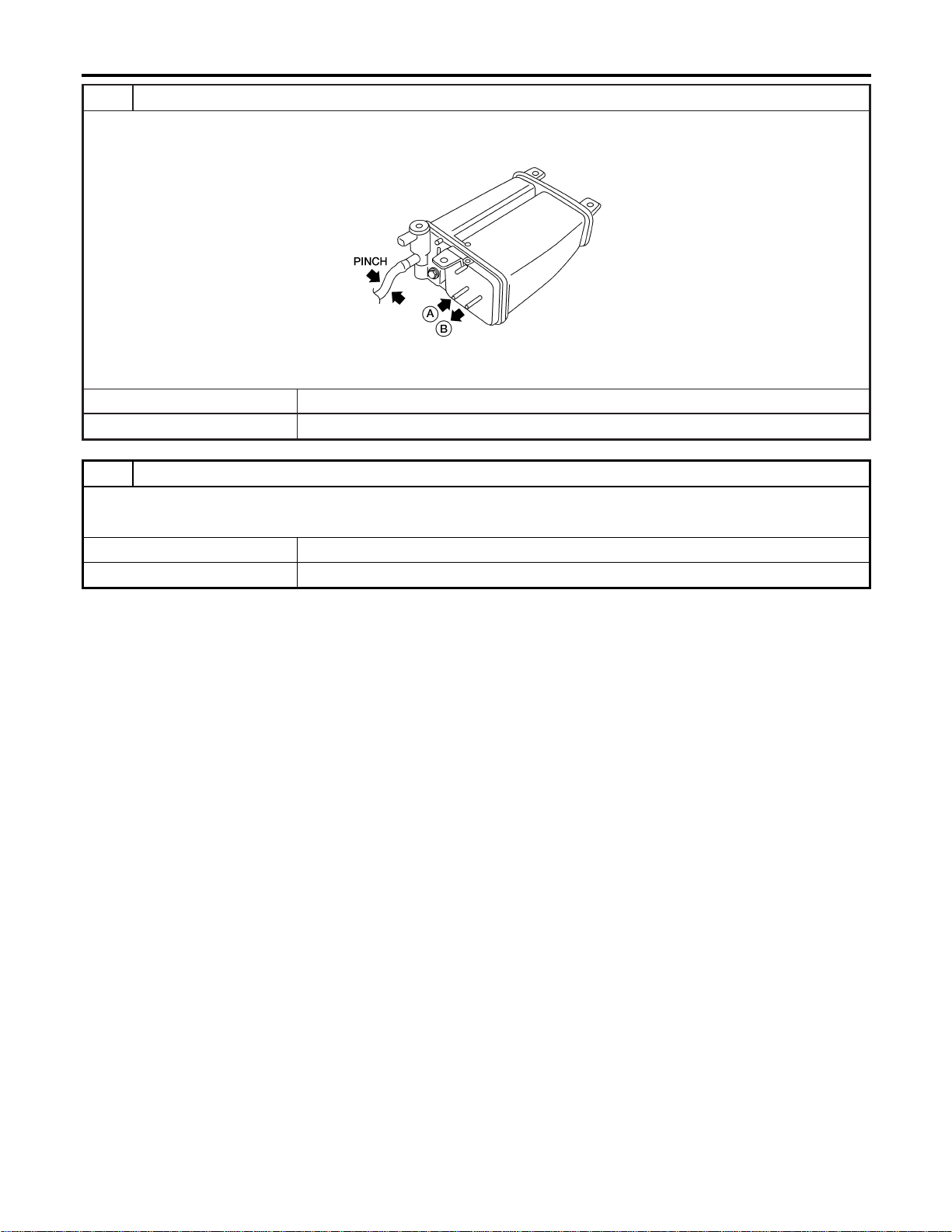
6 CHECK EVAP CANISTER
1. Pinch the fresh air hose.
2. Blow air into port A and check that it flows freely out of port B.
AEC630A
OK or NG
OK © GO TO 12.
NG © Replace EVAP canister.
7 CHECK BYPASS HOSE
Check bypass hoses for clogging.
OK or NG
OK © GO TO 8.
NG © Repair or replace hoses.
DTC P1491 VACUUM CUT VALVE BYPASS VALVE
Diagnostic Procedure (Cont’d)
EC-634
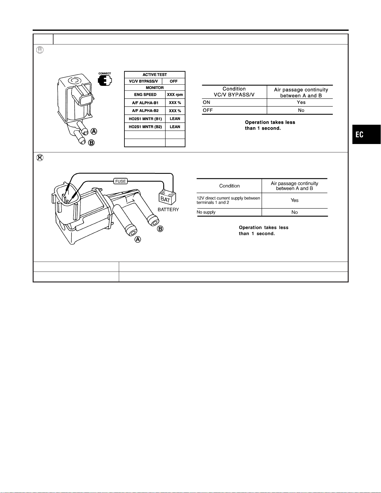
8 CHECK VACUUM CUT VALVE BYPASS VALVE
With CONSULT-II
1. Perform “VC/V BYPASS/V” in “ACTIVE TEST” mode.
2. Check air passage continuity and operation delay time under the following conditions.
SEC156D
Without CONSULT-II
Check air passage continuity and operation delay time under the following conditions.
SEF358X
OK or NG
OK © GO TO 9.
NG © Replace vacuum cut valve bypass valve.
GI
MA
EM
LC
FE
CL
MT
AT
AX
SU
BR
ST
RS
BT
HA
SC
EL
IDX
DTC P1491 VACUUM CUT VALVE BYPASS VALVE
Diagnostic Procedure (Cont’d)
EC-635
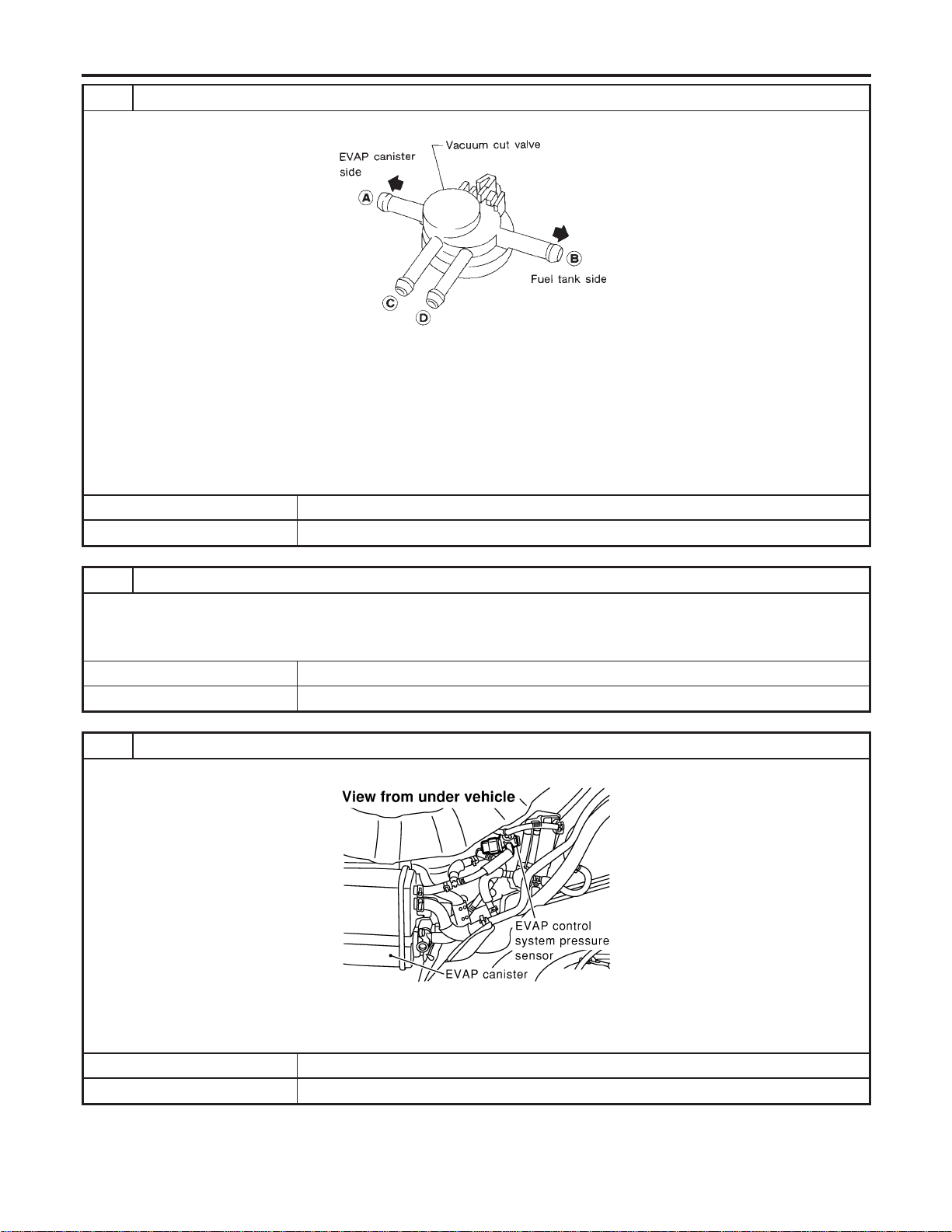
9 CHECK VACUUM CUT VALVE
Check vacuum cut valve as follows:
SEF379Q
a. Plug port C and D with fingers.
b. Apply vacuum to port A and check that there is no suction from port B.
c. Apply vacuum to port B and check that there is suction from port A.
d. Blow air in port B and check that there is a resistance to flow out of port A.
e. Open port C and D.
f. Blow air in port A check that air flows freely out of port C.
g. Blow air in port B check that air flows freely out of port D.
OK or NG
OK © GO TO 10.
NG © Replace vacuum cut valve.
10 CHECK EVAP CONTROL SYSTEM PRESSURE SENSOR HOSE
1. Turn ignition switch “OFF”.
2. Check disconnection or improper connection of hose connected to EVAP control system pressure sensor.
OK or NG
OK © GO TO 11.
NG © Repair or replace.
11 CHECK EVAP CONTROL SYSTEM PRESSURE SENSOR CONNECTOR
1. Disconnect EVAP control system pressure sensor harness connector.
SEF268X
2. Check connectors for water.
Water should not exist.
OK or NG
OK © GO TO 12.
NG © Replace EVAP control system pressure sensor.
DTC P1491 VACUUM CUT VALVE BYPASS VALVE
Diagnostic Procedure (Cont’d)
EC-636
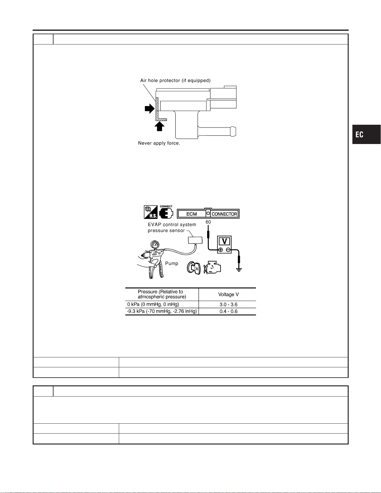
12 CHECK EVAP CONTROL SYSTEM PRESSURE SENSOR
1. Remove EVAP control system pressure sensor with its harness connector connected.
CAUTION:
Never apply force to the air hole protector of the sensor if equipped.
SEF799W
2. Remove hose from EVAP control system pressure sensor.
3. Turn ignition switch “ON”.
4. Use pump to apply vacuum and pressure to EVAP control system pressure sensor as shown in figure.
CAUTION:
I Always calibrate the vacuum pump gauge when using it.
I Do not apply below −20 kPa (−150 mmHg, −5.91 inHg) or over 20 kPa (150 mmHg, 5.91 inHg) of pressure.
5. Check input voltage between ECM terminal 84 and ground.
SEC908C
MTBL1159
CAUTION:
Discard and EVAP control system pressure sensor which has been dropped from a height of more than 0.5 m
(19.7 in) onto a hard surface such as a concrete floor; use a new one.
OK or NG
OK © GO TO 13.
NG © Replace EVAP control system pressure sensor.
13 CHECK RUBBER TUBE FOR CLOGGING
1. Disconnect rubber tube connected to EVAP canister vent control valve.
2. Check the rubber tube for clogging.
OK or NG
OK © GO TO 14.
NG © Clean the rubber tube using an air blower.
GI
MA
EM
LC
FE
CL
MT
AT
AX
SU
BR
ST
RS
BT
HA
SC
EL
IDX
DTC P1491 VACUUM CUT VALVE BYPASS VALVE
Diagnostic Procedure (Cont’d)
EC-637
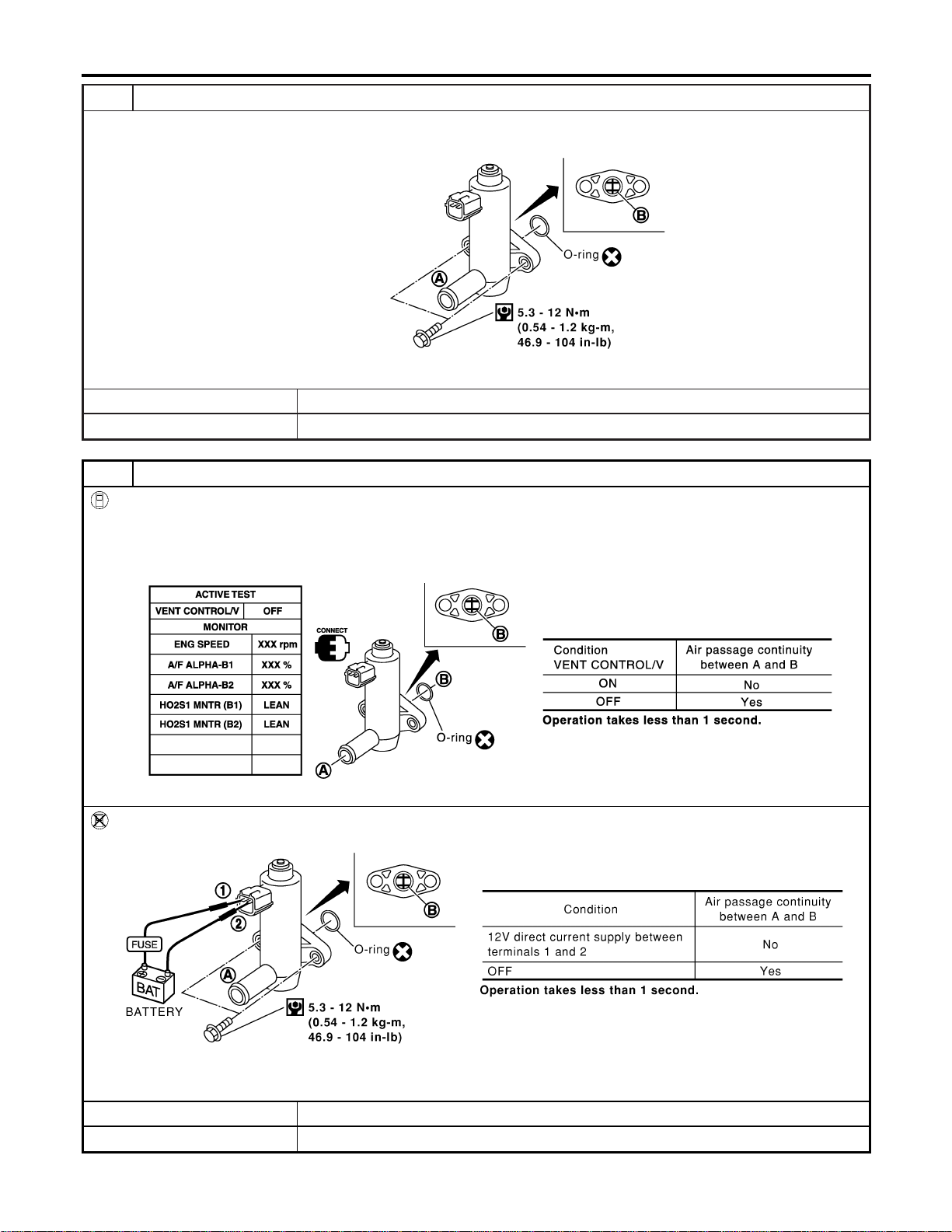
14 CHECK EVAP CANISTER VENT CONTROL VALVE-I
1. Remove EVAP canister vent control valve from EVAP canister.
2. Check portion B of EVAP canister vent control valve for being rusted.
SEF376Z
OK or NG
OK © GO TO 15.
NG © Replace EVAP canister vent control valve.
15 CHECK EVAP CANISTER VENT CONTROL VALVE-II
With CONSULT-II
1. Reconnect harness disconnected connectors.
2. Turn ignition switch ON.
3. Perform “VENT CONTROL/V” in “ACTIVE TEST” mode.
4. Check air passage continuity and operation delay time.
SEC158D
Without CONSULT-II
Check air passage continuity and operation delay time under the following conditions.
SEF378Z
Make sure new O-ring is installed properly.
OK or NG
OK © GO TO 17.
NG © GO TO 16.
DTC P1491 VACUUM CUT VALVE BYPASS VALVE
Diagnostic Procedure (Cont’d)
EC-638
16 CHECK EVAP CANISTER VENT CONTROL VALVE-III
1. Clean the air passage (Portion A to B) of EVAP canister vent control valve using an air blower.
2. Perform the Test No. 15 again.
OK or NG
OK © GO TO 17.
NG © Replace EVAP canister vent control valve.
17 CHECK INTERMITTENT INCIDENT
Refer to “TROUBLE DIAGNOSIS FOR INTERMITTENT INCIDENT”, EC-156.
© INSPECTION END
GI
MA
EM
LC
FE
CL
MT
AT
AX
SU
BR
ST
RS
BT
HA
SC
EL
IDX
DTC P1491 VACUUM CUT VALVE BYPASS VALVE
Diagnostic Procedure (Cont’d)
EC-639
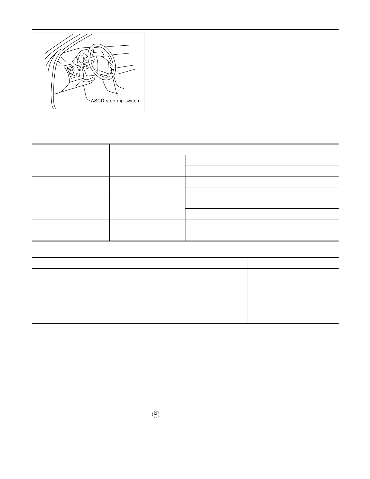
SEC005D
Component Description
NFEC1208
ASCD steering switch has variant values of electrical resistance for
each button. ECM reads voltage variation of switch, and deter-
mines which button is operated.
Refer to EC-53 for the ASCD function.
CONSULT-II Reference Value in Data Monitor
Mode
NFEC1209
Specification data are reference values.
MONITOR ITEM CONDITION SPECIFICATION
MAIN SW I Ignition switch: ON
I CRUISE switch pressed ON
I CRUISE switch released OFF
CANCEL SW I Ignition switch: ON
I CANCEL switch pressed ON
I CANCEL switch released OFF
RESUME/ACC SW I Ignition switch: ON
I ACCEL RES switch pressed ON
I ACCEL RES switch released OFF
SET SW I Ignition switch: ON
I COAST/SET switch pressed ON
I COAST/SET switch released OFF
On Board Diagnosis Procedure
NFEC1462
DTC No. Trouble diagnosis name DTC Detecting Condition Possible cause
P1564
1564
ASCD steering switch
I An excessively high voltage signal
from the ASCD steering switch is
sent to ECM.
I ECM detects that input signal from
the ASCD steering switch is out of
the specified range.
I ECM detects that the ASCD steer-
ing switch is stuck ON.
I Harness or connectors
(The ASCD steering switch circuit
is open or shorted.)
I ASCD steering switch
I ECM
DTC Confirmation Procedure
NFEC1463
NOTE:
If “DTC Confirmation Procedure” has been previously conducted,
always turn ignition switch “OFF” and wait at least 10 seconds
before conducting the next test.
With CONSULT-II
1. Turn ignition switch “ON”.
2. Select “DATA MONITOR” mode with CONSULT-II.
3. Wait at least 10 seconds.
4. Press “CRUISE” switch for at least 10 seconds, then release
DTC P1564 ASCD STEERING SWITCH
Component Description
EC-640

it and wait at least 10 seconds.
5. Press “ACCEL/RES” switch for at least 10 seconds, then
release it and wait at least 10 seconds.
6. Press “COAST/SET” switch for at least 10 seconds, then
release it and wait at least 10 seconds.
7. Press “CANCEL” switch for at least 10 seconds, then release
it and wait at least 10 seconds.
8. If 1st trip DTC is detected, go to “Diagnostic Procedure”,
EC-644.
With GST
Follow the procedure “With CONSULT-II” above.
GI
MA
EM
LC
FE
CL
MT
AT
AX
SU
BR
ST
RS
BT
HA
SC
EL
IDX
DTC P1564 ASCD STEERING SWITCH
DTC Confirmation Procedure (Cont’d)
EC-641
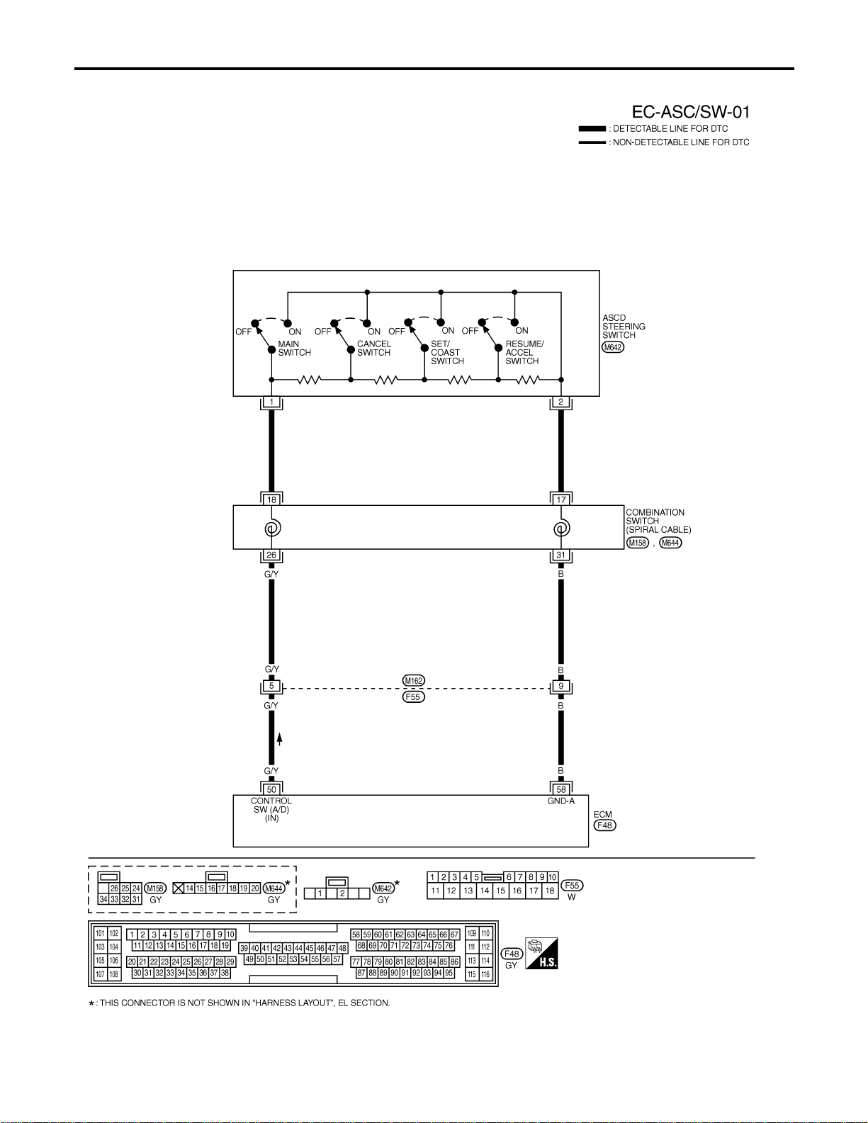
Wiring Diagram
NFEC1464
MEC924D
DTC P1564 ASCD STEERING SWITCH
Wiring Diagram
EC-642
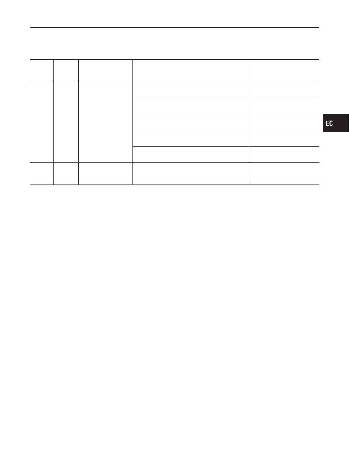
Specification data are reference values and are measured between each terminal and ground.
CAUTION:
Do not use ECM ground terminals when measuring input/output voltage. Doing so may result in dam-
age to the ECM’s transistor. Use a ground other than ECM terminals, such as the ground.
TERMI-
NAL
NO.
WIRE
COLOR
ITEM CONDITION DATA (DC Voltage)
50 G/Y ASCD steering switch
[Ignition switch “ON”]
I ASCD steering switch is “OFF”.
Approximately 4.0V
[Ignition switch “ON”]
I CRUISE switch is “ON”.
Approximately 0V
[Ignition switch “ON”]
I CANCEL switch is “ON”.
Approximately 1V
[Ignition switch “ON”]
I COAST/SET switch is “ON”.
Approximately 2V
[Ignition switch “ON”]
I ACCEL/RES switch is “ON”.
Approximately 3V
58 B Sensors’ ground
[Engine is running]
I Warm-up condition
I Idle speed
Approximately 0V
GI
MA
EM
LC
FE
CL
MT
AT
AX
SU
BR
ST
RS
BT
HA
SC
EL
IDX
DTC P1564 ASCD STEERING SWITCH
Wiring Diagram (Cont’d)
EC-643
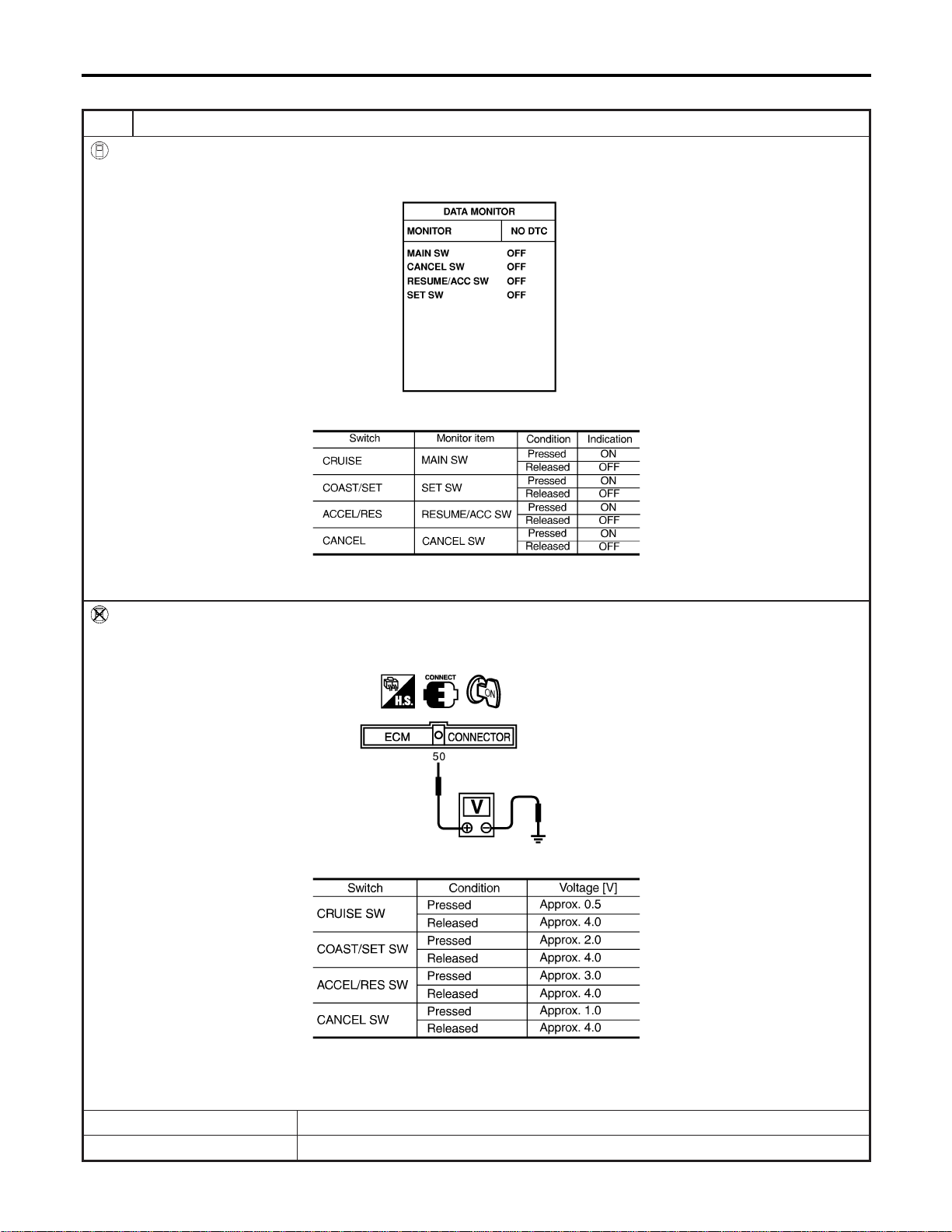
Diagnostic Procedure
NFEC1465
1 CHECK ASCD STEERING SWITCH CIRCUIT
With CONSULT-II
1. Turn ignition switch “ON”.
2. Select “MAIN SW”, “RESUME/ACC SW”, “SET SW” and “CANCEL SW” in “DATA MONITOR” mode with CONSULT-II.
SEC006D
3. Check each item indication under the following conditions.
MTBL1193
Without CONSULT-II
1. Turn ignition switch “ON”.
2. Check voltage between ECM terminal 50 and ground with pressing each button.
SEC007D
MTBL1133
Refer to Wiring Diagram.
OK or NG
OK © GO TO 4.
NG © GO TO 2.
DTC P1564 ASCD STEERING SWITCH
Diagnostic Procedure
EC-644
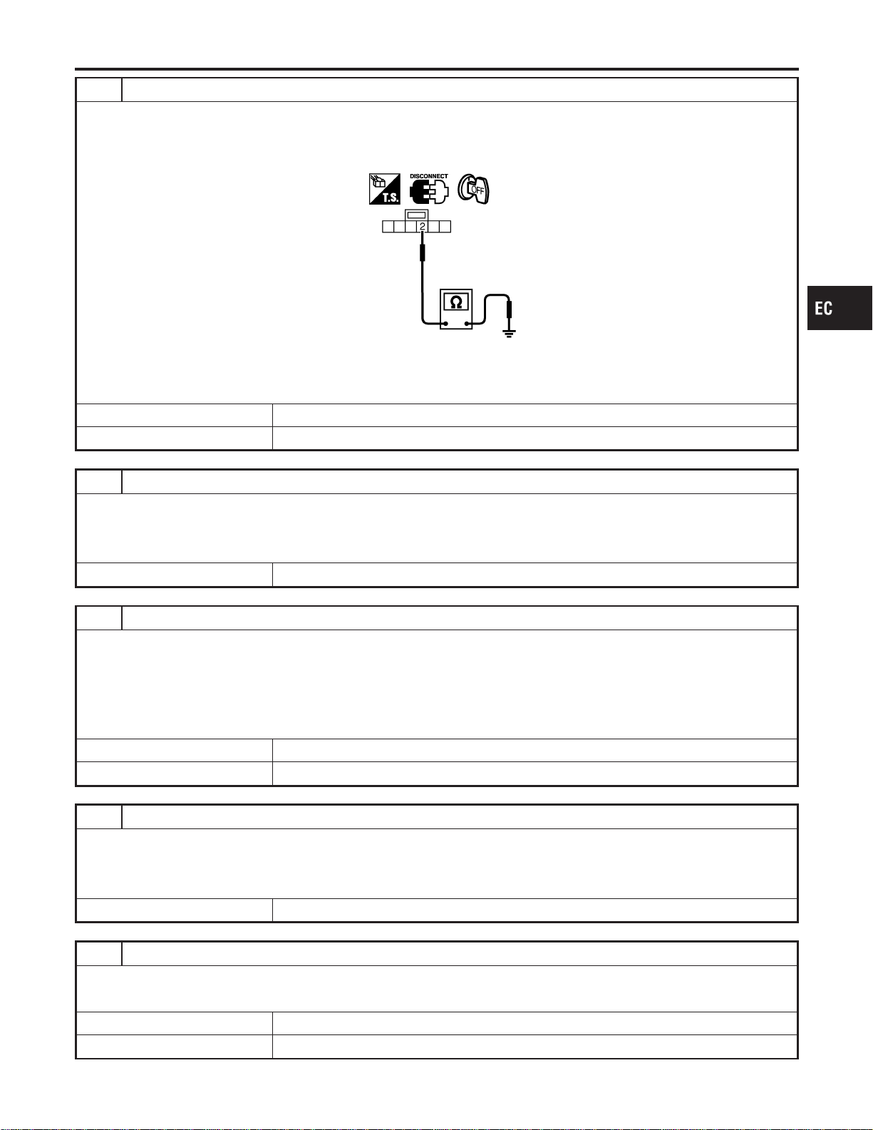
2 CHECK ASCD STEERING SWITCH GROUND CIRCUIT FOR OPEN AND SHORT
1. Turn ignition switch “OFF”.
2. Disconnect ASCD steering harness connector.
3. Check harness continuity between switch terminal 2 and ground. Refer to Wiring Diagram.
SEC198D
Continuity should exist.
4. Also check harness for short to power.
OK or NG
OK © GO TO 4.
NG © GO TO 3.
3 DETECT MALFUNCTIONING PART
Check the following.
I Harness connectors M162, F55
I Combination switch (spiral cable)
I Harness for open and short between ECM and ASCD steering switch
© Repair open circuit or short to power in harness or connectors.
4 CHECK ASCD STEERING SWITCH INPUT SIGNAL CIRCUIT FOR OPEN AND SHORT
1. Disconnect ECM harness connector.
2. Check harness continuity between ECM terminal 50 and ASCD steering switch terminal 1.
Refer to Wiring Diagram.
Continuity should exist.
3. Also check harness for short to ground and short to power.
OK or NG
OK © GO TO 6.
NG © GO TO 5.
5 DETECT MALFUNCTIONING PART
Check the following.
I Harness connectors M162, F55
I Combination switch (spiral cable)
I Harness for open and short between ECM and ASCD steering switch
© Repair open circuit or short to ground or short to power in harness or connectors.
6 CHECK ASCD STEERING SWITCH
Refer to “Component Inspection”, EC-646.
OK or NG
OK © GO TO 7.
NG © Replace ASCD steering switch.
GI
MA
EM
LC
FE
CL
MT
AT
AX
SU
BR
ST
RS
BT
HA
SC
EL
IDX
DTC P1564 ASCD STEERING SWITCH
Diagnostic Procedure (Cont’d)
EC-645
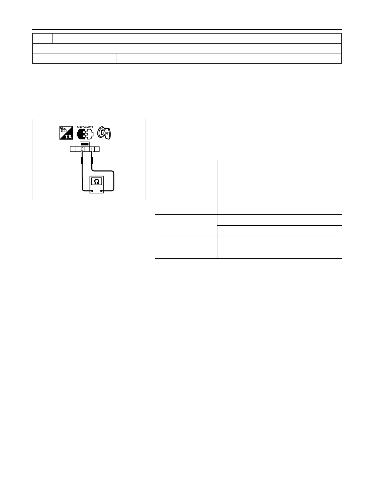
7 CHECK INTERMITTENT INCIDENT
Refer to “TROUBLE DIAGNOSIS FOR INTERMITTENT INCIDENT”, EC-156.
© INSPECTION END
SEC008D
Component Inspection
NFEC1215
ASCD STEERING SWITCH
1. Disconnect ASCD steering switch.
2. Check continuity between terminals 1 and 2 by pushing each
switch.
Switch Condition Resistance [Ω]
CRUISE SW
Pressed Approx. 0
Released Approx. 4,000
COAST/SET SW
Pressed Approx. 660
Released Approx. 4,000
ACCEL/RES SW
Pressed Approx. 1,480
Released Approx. 4,000
CANCEL SW
Pressed Approx. 250
Released Approx. 4,000
DTC P1564 ASCD STEERING SWITCH
Diagnostic Procedure (Cont’d)
EC-646
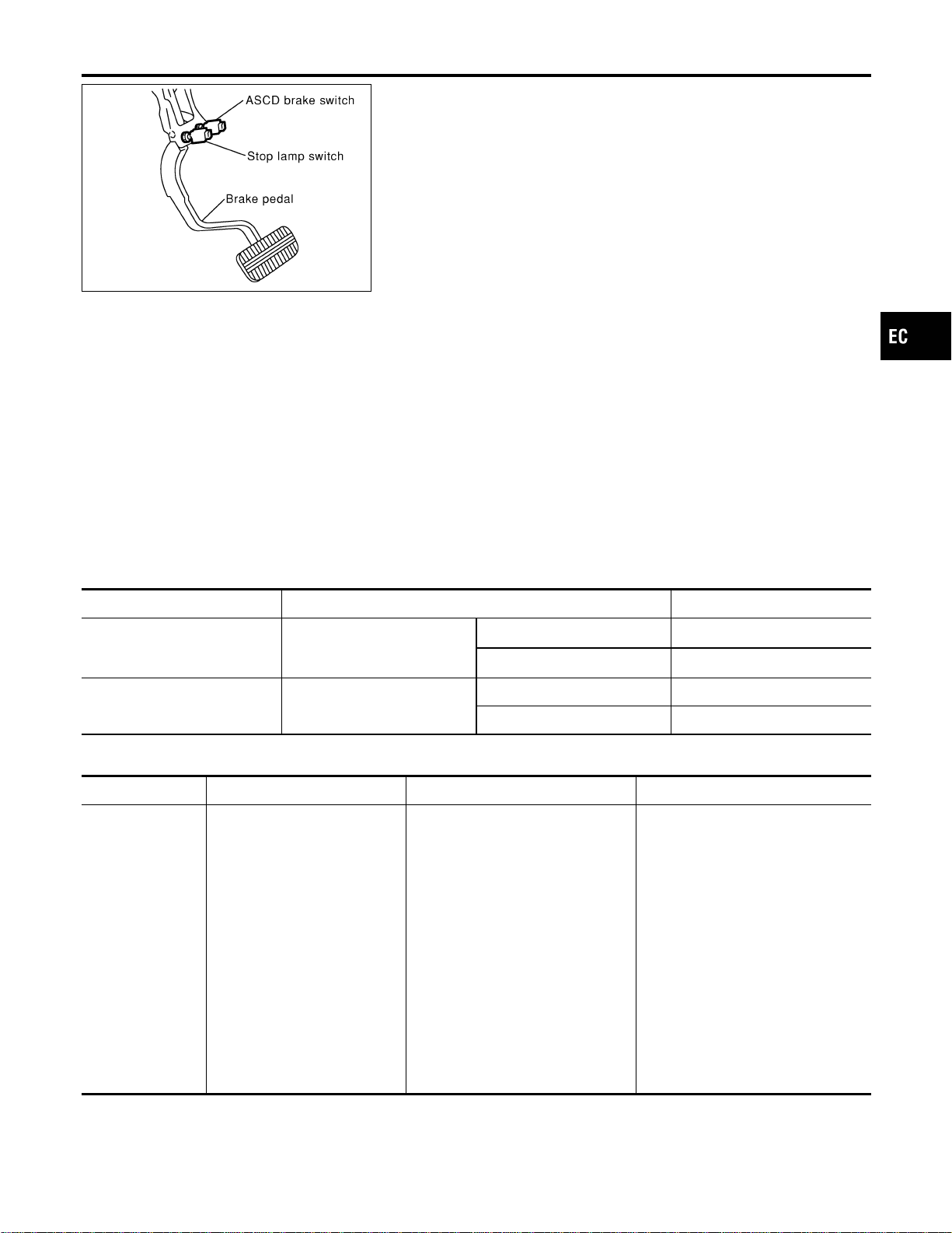
SEC009D
Component Description
NFEC1466
NOTE:
I If DTC P1572 is displayed with DTC P0605, first perform
the trouble diagnosis for DTC P0605. Refer to EC-455.
I If DTC P1572 is displayed with DTC P1706, first perform
the trouble diagnosis for DTC P1706. Refer to EC-667.
I If DTC P1572 is displayed with DTC P1805, first perform
the trouble diagnosis for DTC P1805. Refer to EC-678.
When the brake pedal is depressed, ASCD brake switch is turned
OFF and stop lamp switch is turned ON.
ECM detects the state of the brake pedal by this input of two kinds
(ON/OFF signal).
Refer to EC-53 for the ASCD function.
CONSULT-II Reference Value in Data Monitor
Mode
NFEC1217
Specification data are reference values.
MONITOR ITEM CONDITION SPECIFICATION
BRAKE SW 1
(ASCD brake switch)
I Ignition switch: ON
I Shift lever: Except “N” and
“P” position (AT models)
I Brake pedal fully released ON
I Brake pedal depressed OFF
BRAKE SW 2
(Stop lamp switch)
I Ignition switch: ON
I Brake pedal fully released OFF
I Brake pedal depressed ON
On Board Diagnosis Procedure
NFEC1467
DTC Trouble diagnosis name DTC Detecting Condition Possible cause
P1572
1572
ASCD brake switch
When the vehicle speed is above 30
km/h (19 MPH), ON signal from the
stop lamp switch and ASCD brake
switch are sent to the ECM at the
same time.
I Harness or connectors
(The stop lamp switch circuit is
open or shorted.)
I Harness or connectors
(The ASCD brake switch circuit is
open or shorted.)
I ASCD brake switch
I Stop lamp switch
I Harness or connectors
(The ASCD brake switch or stop
lamp switch circuit is open or
shorted.)
I Incorrect stop lamp switch installa-
tion
I Incorrect ASCD brake switch
installation
I ECM
GI
MA
EM
LC
FE
CL
MT
AT
AX
SU
BR
ST
RS
BT
HA
SC
EL
IDX
DTC P1572 ASCD BRAKE SWITCH
Component Description
EC-647
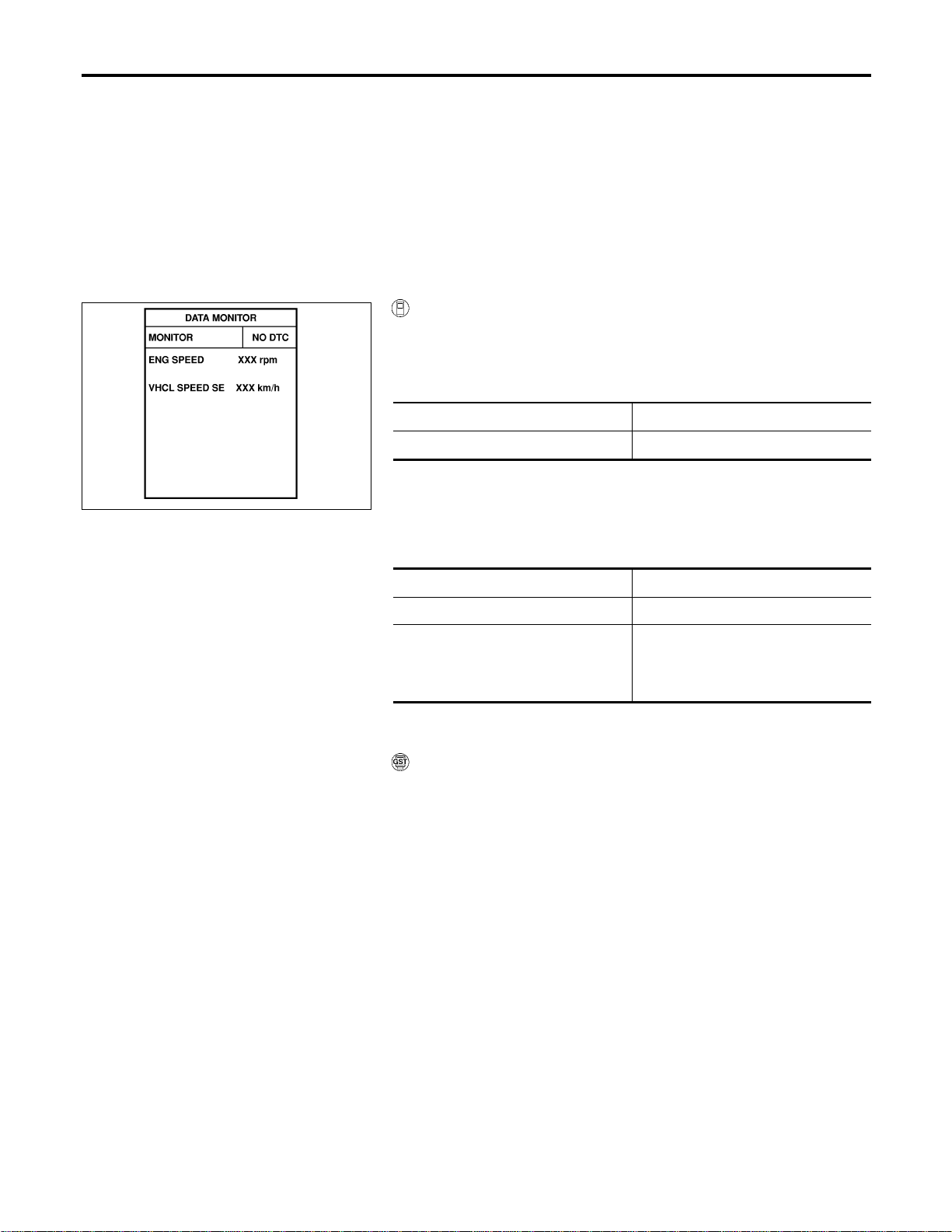
DTC Confirmation Procedure
NFEC1468
CAUTION:
Always drive vehicle at a safe speed.
NOTE:
If “DTC Confirmation Procedure” has been previously conducted,
always turn ignition switch “OFF” and wait at least 10 seconds
before conducting the next test.
TESTING CONDITION:
Steps 3 and 4 may be conducted with the drive wheels lifted
in the shop or by driving the vehicle. If a road test is expected
to be easier, it is unnecessary to lift the vehicle.
SEC010D
With CONSULT-II
1) Start engine (TCS switch “OFF”).
2) Select “DATA MONITOR” mode with CONSULT-II.
3) Drive the vehicle for at least 5 consecutive seconds under the
following condition.
VHCL SPEED SE More than 30 km/h (19 MPH)
Selector lever Suitable position
If 1st trip DTC is detected, go to “Diagnostic Procedure”,
EC-651.
If 1st rip DTC is not detected, go to the following step.
4) Drive the vehicle for at least 5 consecutive seconds under the
following condition.
VHCL SPEED SE More than 30 km/h (19 MPH)
Selector lever Suitable position
Driving location
Depress the brake pedal for more
than five seconds so as not to come
off from the above-mentioned condi-
tion.
5) If 1st trip DTC is detected, go to “Diagnostic Procedure”,
EC-651.
With GST
Follow the procedure “With CONSULT-II” above.
DTC P1572 ASCD BRAKE SWITCH
DTC Confirmation Procedure
EC-648
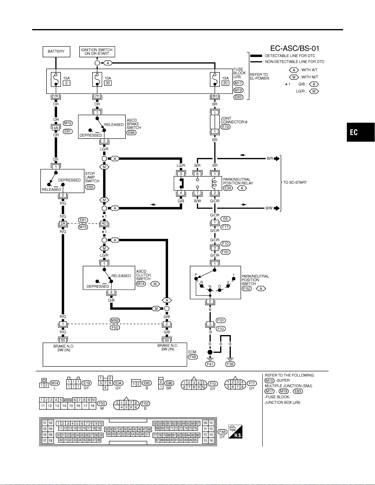
Wiring Diagram
NFEC1221
MEC693D
GI
MA
EM
LC
FE
CL
MT
AT
AX
SU
BR
ST
RS
BT
HA
SC
EL
IDX
DTC P1572 ASCD BRAKE SWITCH
Wiring Diagram
EC-649

Specification data are reference values and are measured between each terminal and ground.
CAUTION:
Do not use ECM ground terminals when measuring input/output voltage. Doing so may result in dam-
age to the ECM’s transistor. Use a ground other than ECM terminals, such as the ground.
TERMI-
NAL
NO.
WIRE
COLOR
ITEM CONDITION DATA (DC Voltage)
55 R/G Stop lamp switch
[Ignition switch “ON”]
I Brake pedal is fully released
Approximately 0V
[Ignition switch “ON”]
I Brake pedal is depressed
BATTERY VOLTAGE
(11 - 14V)
59 G/B ASCD brake switch
[Ignition switch “ON”]
I Brake pedal is fully released
I Clutch pedal is fully released (M/T models)
BATTERY VOLTAGE
(11 - 14V)
[Ignition switch “ON”]
I Brake pedal is depressed
I Clutch pedal is fully depressed (M/T models)
Approximately 0V
DTC P1572 ASCD BRAKE SWITCH
Wiring Diagram (Cont’d)
EC-650
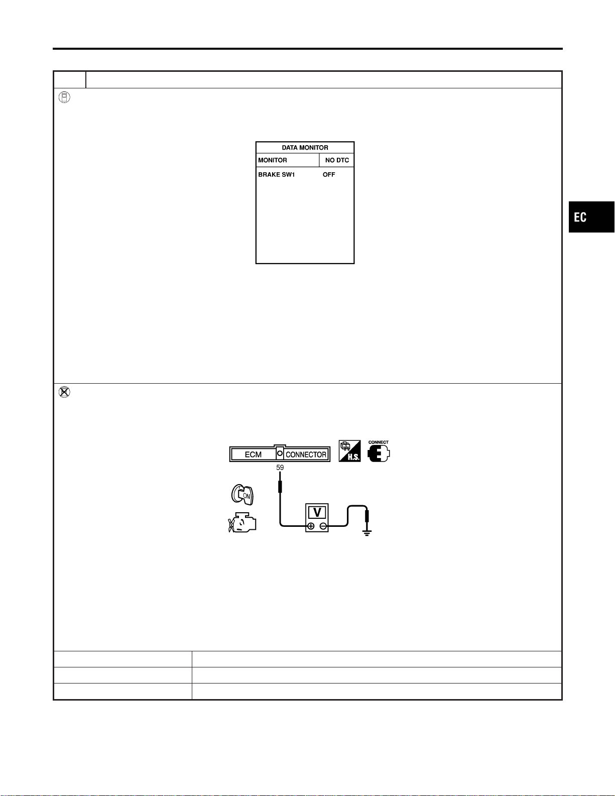
Diagnostic Procedure
NFEC1222
1 CHECK OVERALL FUNCTION-I
With CONSULT-II
1. Turn ignition switch “ON”.
2. Select “BRAKE SW1” in “DATA MONITOR” mode with CONSULT-II.
3. Check the indication of “BRAKE SW1” under the following conditions.
SEC011D
A/T models
When brake pedal is depressed or A/T selector lever is in “N” or “P” range:
BRAKE SW1 OFF
When brake pedal is released and A/T selector lever is not “N” or “P” range:
BRAKE SW1 ON
M/T models
When clutch pedal or brake pedal is depressed:
BRAKE SW1 OFF
When clutch pedal and brake pedal are released:
BRAKE SW1 ON
Without CONSULT-II
1. Turn ignition switch “ON”.
2. Check voltage between ECM terminal 59 and ground under the following conditions.
SEC012D
When brake or clutch pedal is depressed (M/T), or when brake pedal is depressed or A/T selector lever is in “N” or “P”
range (A/T):
Approx. 0V
When brake and clutch pedal are released (M/T), or when both brake pedal is released and A/T selector lever is not in
“N” or “P” range (A/T):
Battery voltage should exist.
Refer to Wiring Diagram.
OK or NG
OK © GO TO 2.
NG © A/T MODELS: GO TO 3.
NG © M/T MODELS: GO TO 19.
GI
MA
EM
LC
FE
CL
MT
AT
AX
SU
BR
ST
RS
BT
HA
SC
EL
IDX
DTC P1572 ASCD BRAKE SWITCH
Diagnostic Procedure
EC-651
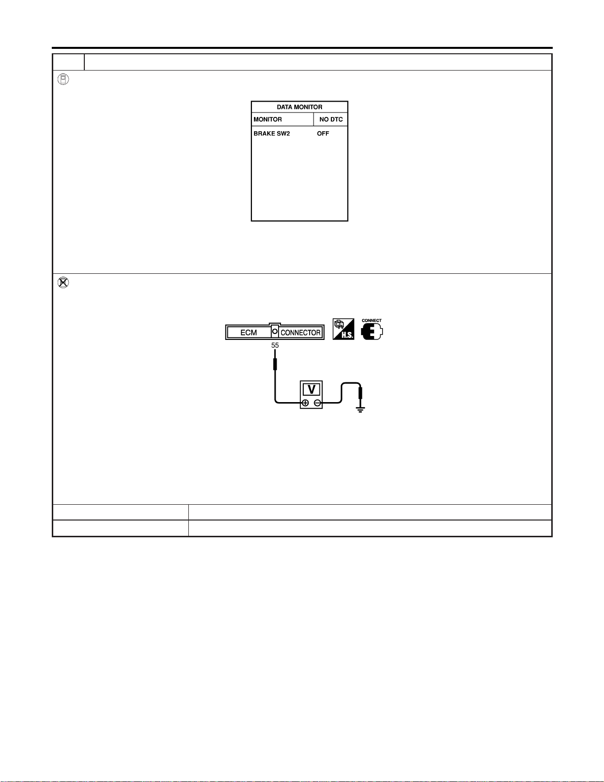
2 CHECK OVERALL FUNCTION-II
With CONSULT-II
See “BRAKE SW2” indication in “DATA MONITOR” mode.
SEC013D
When brake pedal is released:
BRAKE SW2 OFF
When brake pedal is depressed:
BRAKE SW2 ON
Without CONSULT-II
Check voltage between ECM terminal 55 and ground under the following conditions.
SEC014D
When brake pedal is released:
Approx. 0V
When brake pedal is depressed:
Battery voltage should exist.
Refer to Wiring Diagram.
OK or NG
OK © GO TO 33.
NG © GO TO 28.
DTC P1572 ASCD BRAKE SWITCH
Diagnostic Procedure (Cont’d)
EC-652

3 CHECK ASCD BRAKE SWITCH CIRCUIT-I
1. Turn ignition switch “OFF”.
2. Disconnect park/neutral position relay harness connector.
3. Turn ignition switch “ON”.
4. Check voltage between park/neutral position relay terminal 3 and ground under the following conditions.
SEC209D
MTBL1259
OK or NG
OK © GO TO 8.
NG © GO TO 4.
4 CHECK ASCD BRAKE SWITCH POWER SUPPLY CIRCUIT
1. Turn ignition switch “OFF”.
2. Disconnect ASCD brake switch harness connector.
3. Turn ignition switch “ON”.
4. Check voltage between ASCD brake switch terminal 1 and ground with CONSULT-II or tester.
PBIB0857E
Voltage: Battery voltage
OK or NG
OK © GO TO 6.
NG © GO TO 5.
5 DETECT MALFUNCTIONING PART
Check the following.
I Fuse block (J/B) connector E83
I 10A fuse
I Harness for open or short between ASCD brake switch and fuse
© Repair open circuit or short to ground or short to power in harness or connectors.
GI
MA
EM
LC
FE
CL
MT
AT
AX
SU
BR
ST
RS
BT
HA
SC
EL
IDX
DTC P1572 ASCD BRAKE SWITCH
Diagnostic Procedure (Cont’d)
EC-653
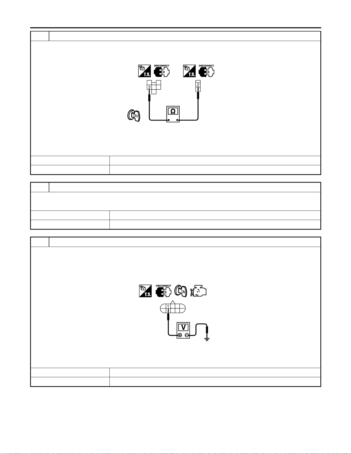
6 CHECK ASCD BRAKE SWITCH INPUT SIGNAL CIRCUIT FOR OPEN AND SHORT
1. Turn ignition switch “OFF”.
2. Check continuity between ASCD brake switch terminal 2 and park/neutral position relay terminal 3.
SEC213D
Continuity should exist.
3. Also check harness for short to ground and short to power.
OK or NG
OK © GO TO 7.
NG © Repair open circuit or short to ground or short to power in harness or connectors.
7 CHECK ASCD BRAKE SWITCH
Refer to “Component Inspection”, EC-661.
OK or NG
OK © GO TO 8.
NG © Replace ASCD brake switch.
8 CHECK PARK/NEUTRAL POSITION (PNP) RELAY CIRCUIT
1. Turn ignition switch “OFF”.
2. Disconnect park/neutral position switch harness connector.
3. Turn ignition switch “ON”.
4. Check voltage between park/neutral position (PNP) switch terminal 1 and ground with CONSULT-II or tester.
SEC214D
Voltage: Battery voltage
OK or NG
OK © GO TO 13.
NG © GO TO 9.
DTC P1572 ASCD BRAKE SWITCH
Diagnostic Procedure (Cont’d)
EC-654
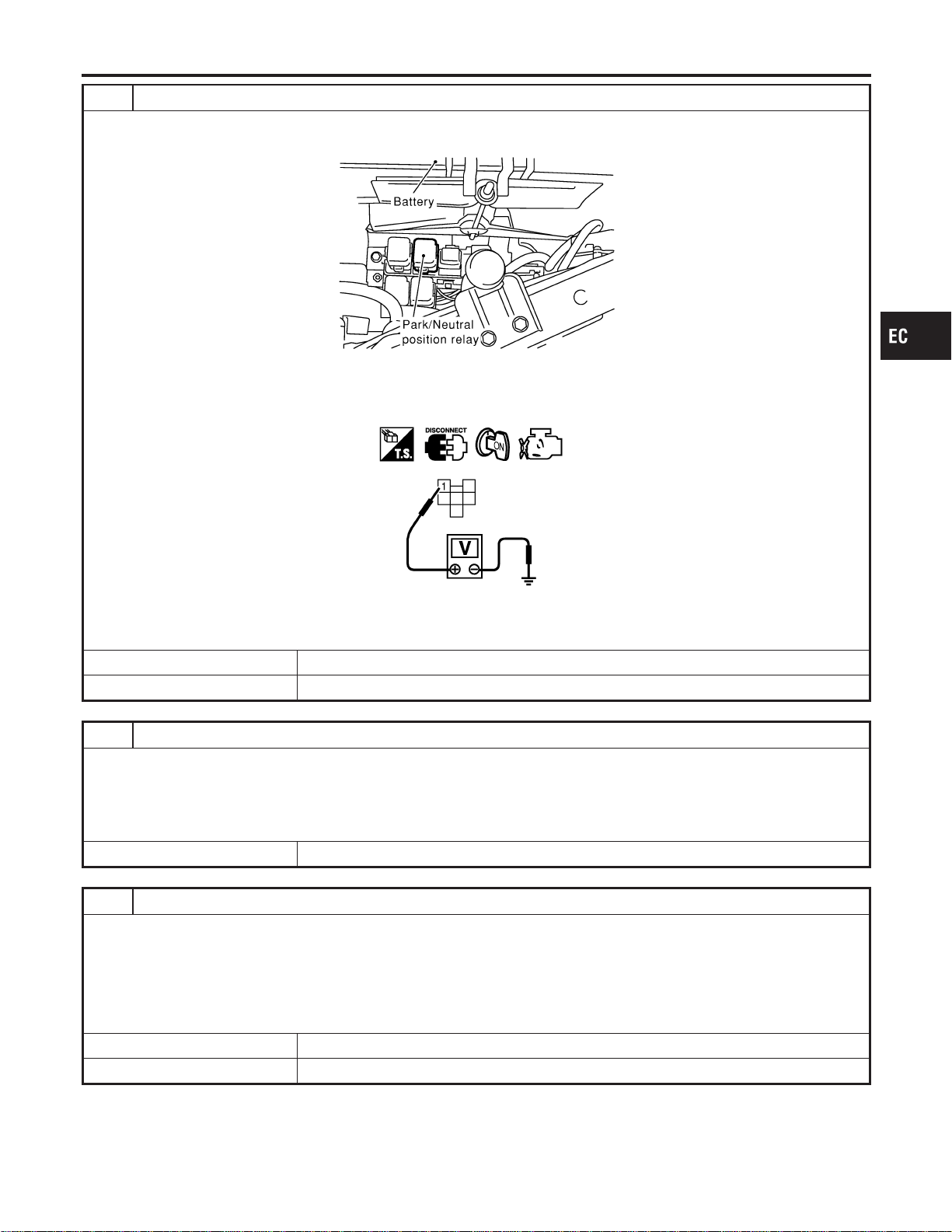
9 CHECK PARK/NEUTRAL POSITION (PNP) RELAY POWER SUPPLY CIRCUIT
1. Turn ignition switch “OFF”.
2. Disconnect park/neutral position (PNP) relay.
SEC018D
3. Turn ignition switch “ON”.
4. Check voltage between park/neutral position (PNP) relay terminal 1 and ground with CONSULT-II or tester.
SEC019D
Voltage: Battery voltage
OK or NG
OK © GO TO 11.
NG © GO TO 10.
10 DETECT MALFUNCTIONING PART
Check the following.
I Fuse block (J/B) connector E83
I 15A fuse
I Joint connector-8
I Harness for open or short between park/neutral position (PNP) relay and fuse
© Repair open circuit or short to ground in harness or connectors.
11 CHECK PARK/NEUTRAL POSITION RELAY CIRCUIT FOR OPEN AND SHORT
1. Turn ignition switch “OFF”.
2. Check continuity between park/neutral position (PNP) relay terminal 2 and park/neutral position switch terminal 1.
Refer to Wiring Diagram.
Continuity should exist.
3. Also check harness for short to ground and short to power.
OK or NG
OK © GO TO 13.
NG © GO TO 12.
GI
MA
EM
LC
FE
CL
MT
AT
AX
SU
BR
ST
RS
BT
HA
SC
EL
IDX
DTC P1572 ASCD BRAKE SWITCH
Diagnostic Procedure (Cont’d)
EC-655
12 DETECT MALFUNCTIONING PART
Check the following.
I Harness connectors E8, F17
I Harness connectors F10, F151
I Harness for open or short between park/neutral position relay and park/neutral position switch
© Repair open circuit or short to ground or short to power in harness or connectors.
13 CHECK PARK/NEUTRAL POSITION RELAY
Refer to “Component Inspection”, EC-661.
OK or NG
OK © GO TO 28.
NG © Replace park/neutral position relay.
14 CHECK PARK/NEUTRAL POSITION (PNP) SWITCH GROUND CIRCUIT
1. Turn ignition switch “OFF”.
2. Disconnect park/neutral position switch harness connector.
3. Check continuity between park/neutral position (PNP) switch terminal 2 and ground.
Continuity should exist.
4. Also check harness for short to ground and short to power.
OK or NG
OK © GO TO 16.
NG © GO TO 15.
15 DETECT MALFUNCTIONING PART
Check the following.
I Harness connectors F10, F151
I Harness for open or short between park/neutral position (PNP) switch and ground
© Repair open circuit or short to ground or short to power in harness or connectors.
16 CHECK PARK/NEUTRAL POSITION SWITCH
Refer to “Component Inspection”, EC-661.
OK or NG
OK © GO TO 17.
NG © Replace park/neutral position switch.
DTC P1572 ASCD BRAKE SWITCH
Diagnostic Procedure (Cont’d)
EC-656
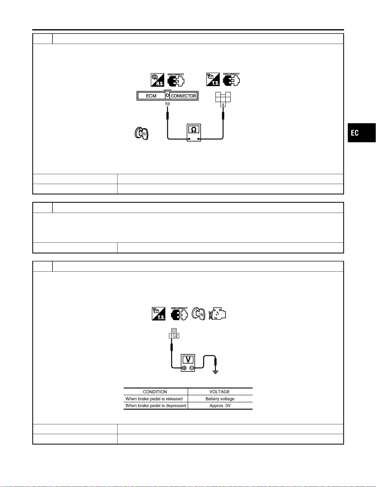
17 CHECK ASCD BRAKE SWITCH INPUT SIGNAL CIRCUIT
1. Turn ignition switch “OFF”.
2. Disconnect ECM harness connector and park/neutral position (PNP) relay harness connector.
3. Check harness continuity between park/neutral position (PNP) relay terminal 4 and ECM terminal 59.
SEC215D
Continuity should exist.
4. Also check harness for short to ground and short to power.
OK or NG
OK © GO TO 28.
NG © GO TO 18.
18 DETECT MALFUNCTIONING PART
Check the following.
I Harness connectors E81, M15
I Harness connectors M162, F55
I Harness for open or short between park/neutral position (PNP) relay and ECM
© Repair open circuit or short to ground or short to power in harness or connectors.
19 CHECK ASCD BRAKE SWITCH CIRCUIT-II
1. Turn ignition switch “OFF”.
2. Disconnect ASCD clutch switch harness connector.
3. Turn ignition switch “ON”.
4. Check voltage between ASCD clutch switch terminal 1 and ground under the following conditions.
PBIB0799E
MTBL1303
OK or NG
OK © GO TO 25.
NG © GO TO 20.
GI
MA
EM
LC
FE
CL
MT
AT
AX
SU
BR
ST
RS
BT
HA
SC
EL
IDX
DTC P1572 ASCD BRAKE SWITCH
Diagnostic Procedure (Cont’d)
EC-657
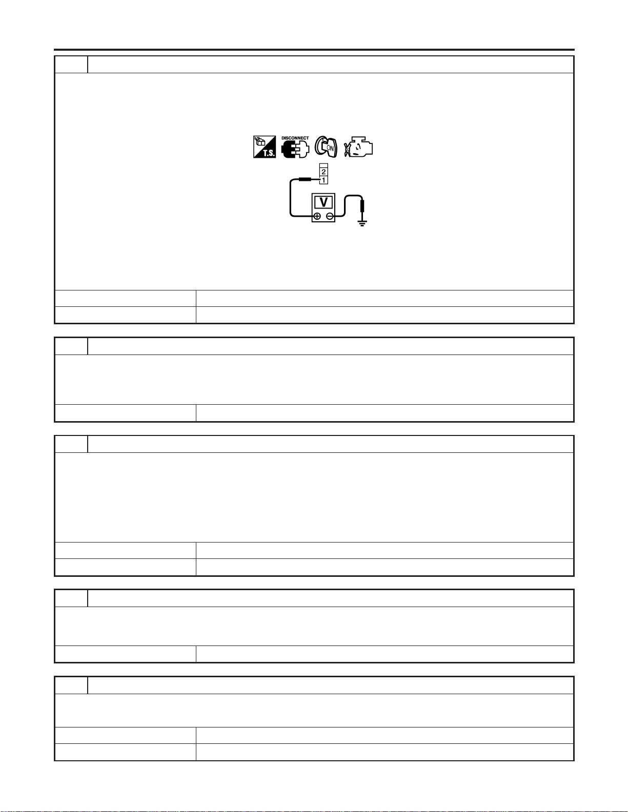
20 CHECK ASCD BRAKE SWITCH POWER SUPPLY CIRCUIT
1. Turn ignition switch “OFF”.
2. Disconnect ASCD brake switch harness connector.
3. Turn ignition switch “ON”.
4. Check voltage between ASCD brake switch terminal 1 and ground with CONSULT-II or tester.
PBIB0857E
Voltage: Battery voltage
OK or NG
OK © GO TO 22.
NG © GO TO 21.
21 DETECT MALFUNCTIONING PART
Check the following.
I Fuse block (J/B) connector E83
I 10A fuse
I Harness for open or short between ASCD brake switch and fuse
© Repair open circuit or short to ground or short to power in harness or connectors.
22 CHECK ASCD BRAKE SWITCH INPUT SIGNAL CIRCUIT FOR OPEN AND SHORT
1. Turn ignition switch “OFF”.
2. Disconnect ASCD clutch switch harness connector.
3. Check continuity between ASCD brake switch terminal 2 and ASCD clutch switch terminal 1.
Refer to Wiring Diagram.
Continuity should exist.
4. Also check harness for short to ground and short to power.
OK or NG
OK © GO TO 24.
NG © GO TO 23.
23 DETECT MALFUNCTIONING PART
Check the following.
I Harness connectors E81, M15
I Harness for open or short between ASCD brake switch and ASCD clutch switch
© Repair open circuit or short to ground or short to power in harness or connectors.
24 CHECK ASCD BRAKE SWITCH
Refer to “Component Inspection”, EC-661.
OK or NG
OK © GO TO 25.
NG © Replace ASCD brake switch.
DTC P1572 ASCD BRAKE SWITCH
Diagnostic Procedure (Cont’d)
EC-658
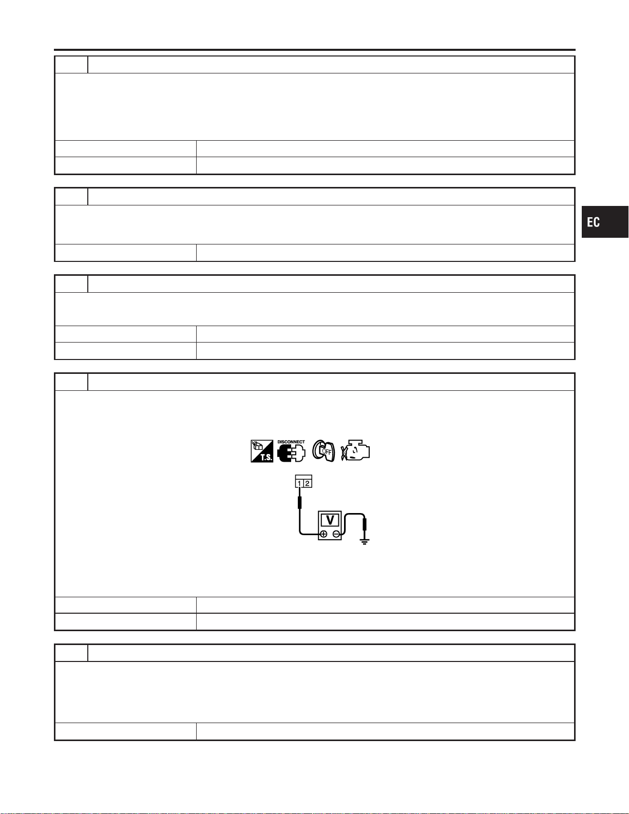
25 CHECK ASCD CLUTCH SWITCH CIRCUIT FOR OPEN AND SHORT
1. Turn ignition switch “OFF”.
2. Check continuity between ASCD clutch switch terminal 2 and ECM terminal 59.
Continuity should exist.
3. Also check harness for short to ground and short to power.
OK or NG
OK © GO TO 27.
NG © GO TO 26.
26 DETECT MALFUNCTIONING PART
Check the following.
I Harness connectors M162, F55
I Harness for open or short between ASCD clutch switch and ECM
© Repair open circuit or short to ground or short to power in harness or connectors.
27 CHECK ASCD CLUTCH SWITCH
Refer to “Component Inspection”, EC-661.
OK or NG
OK © GO TO 28.
NG © Replace ASCD clutch switch.
28 CHECK STOP LAMP SWITCH POWER SUPPLY CIRCUIT
1. Turn ignition switch “OFF”.
2. Disconnect stop lamp switch harness connector.
3. Check voltage between stop lamp switch terminal 1 and ground with CONSULT-II or tester.
PBIB0117E
Voltage: Battery voltage
OK or NG
OK © GO TO 30.
NG © GO TO 29.
29 DETECT MALFUNCTIONING PART
Check the following.
I Fuse block (J/B) connector M17
I 15A fuse
I Harness connectors M15, E81
I Harness for open or short between stop lamp switch and fuse
© Repair open circuit or short to ground in harness or connectors.
GI
MA
EM
LC
FE
CL
MT
AT
AX
SU
BR
ST
RS
BT
HA
SC
EL
IDX
DTC P1572 ASCD BRAKE SWITCH
Diagnostic Procedure (Cont’d)
EC-659
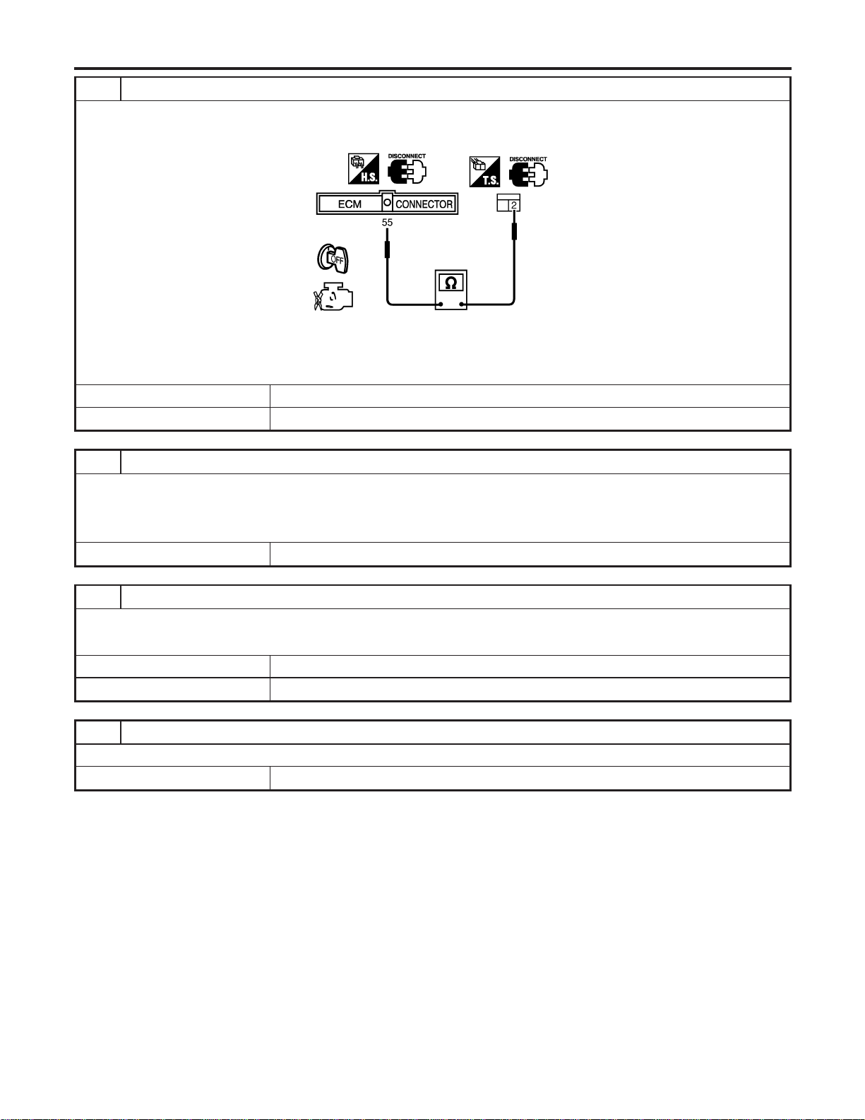
30 CHECK STOP LAMP SWITCH INPUT SIGNAL CIRCUIT FOR OPEN AND SHORT
1. Disconnect ECM harness connector.
2. Check harness continuity between stop lamp switch terminal 2 and ECM terminal 55.
SEC216D
Continuity should exist
3. Also check harness for short to ground and short to power.
OK or NG
OK © GO TO 32.
NG © GO TO 31.
31 DETECT MALFUNCTIONING PART
Check the following.
I Harness connectors M15, E81
I Harness connectors M162, F55
I Harness for open or short between stop lamp switch and ECM
© Repair open circuit or short to ground or short to power in harness or connectors.
32 CHECK STOP LAMP SWITCH
Refer to “Component Inspection”, EC-661.
OK or NG
OK © GO TO 33.
NG © Replace stop lamp switch.
33 CHECK INTERMITTENT INCIDENT
Refer to “TROUBLE DIAGNOSIS FOR INTERMITTENT INCIDENT”, EC-156.
© INSPECTION END
DTC P1572 ASCD BRAKE SWITCH
Diagnostic Procedure (Cont’d)
EC-660
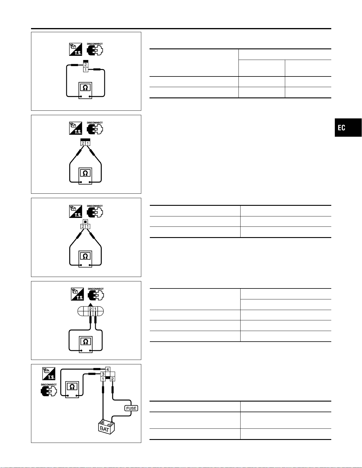
SEC023D
SEC155D
Component Inspection
NFEC1223
ASCD BRAKE SWITCH AND STOP LAMP SWITCH
Condition
Continuity
ASCD brake
switch
Stop lamp switch
When brake pedal is depressed No Yes
When brake pedal is released Yes No
Check each switch after adjusting brake pedal — refer to BR
section.
SEC024D
ASCD CLUTCH SWITCH (FOR M/T MODELS)
Condition Continuity
When clutch pedal is depressed No
When clutch pedal is released Yes
SEC223D
PARK/NEUTRAL POSITION (PNP) SWITCH (FOR A/T MODELS)
A/T selector lever position
Continuity
Between terminals 1 and 2
“P” Yes
“N” Yes
Except “P” and “N” No
SEC224D
PARK/NEUTRAL POSITION (PNP) RELAY (FOR A/T MODELS)
1. Apply 12V direct current between park/neutral position (PNP)
relay terminals 1 and 2.
2. Check continuity between park/neutral position (PNP) relay
Terminals 3 and 4.
Condition Continuity
12V direct current supply between ter-
minals 1 and 2
No
OFF Yes
GI
MA
EM
LC
FE
CL
MT
AT
AX
SU
BR
ST
RS
BT
HA
SC
EL
IDX
DTC P1572 ASCD BRAKE SWITCH
Component Inspection
EC-661

Component Description
NFEC1469
NOTE:
I If DTC P1574 is displayed with DTC U1000, U1001, first
perform the trouble diagnosis for DTC U1000, U1001, refer
to EC-164.
I If DTC P1574 is displayed with DTC P0500, first perform
the trouble diagnosis for DTC P0500. Refer to EC-442.
I If DTC P1574 is displayed with DTC P0605, first perform
the trouble diagnosis for DTC P0605. Refer to EC-455.
ECM receives vehicle speed signals via two different lines, and
detects vehicle speed for ASCD control.
Vehicle speed signals are input from combination meter and TCM
separately.
Signal from TCM is sent via CAN communication line.
Refer to EC-53 for ASCD functions.
On Board Diagnosis Procedure
NFEC1470
DTC Trouble diagnosis name DTC Detecting Condition Possible cause
P1574
1574
ASCD vehicle speed sensor
ECM detects a difference values
between two vehicle speed signals if
they are out of the specified range.
I Harness or connectors
(The CAN communication line is
open or shorted.)
I Harness or connectors
(The combination meter circuit is
open or shorted.)
I Combination meter
I Vehicle speed sensor
I TCM
I ECM
DTC Confirmation Procedure
NFEC1471
CAUTION:
Always drive vehicle at a safe speed.
NOTE:
If “DTC Confirmation Procedure” has been previously conducted,
always turn ignition switch “OFF” and wait at least 10 seconds
before conducting the next test.
TESTING CONDITION:
Step 3 may be conducted with the drive wheels lifted in the
shop or by driving the vehicle. If a road test is expected to be
easier, it is unnecessary to lift the vehicle.
DTC P1574 ASCD VEHICLE SPEED SENSOR
Component Description
EC-662
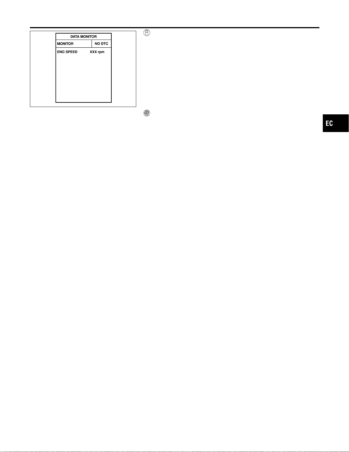
SEF058Y
With CONSULT-II
1) Start engine (TCS switch “OFF”).
2) Select “DATA MONITOR” mode with CONSULT-II.
3) Drive the vehicle at more than 40 km/h (25 MPH).
4) If 1st trip DTC is detected, go to “Diagnostic Procedure”,
EC-665.
With GST
Follow the procedure “With CONSULT-II” above.
GI
MA
EM
LC
FE
CL
MT
AT
AX
SU
BR
ST
RS
BT
HA
SC
EL
IDX
DTC P1574 ASCD VEHICLE SPEED SENSOR
DTC Confirmation Procedure (Cont’d)
EC-663
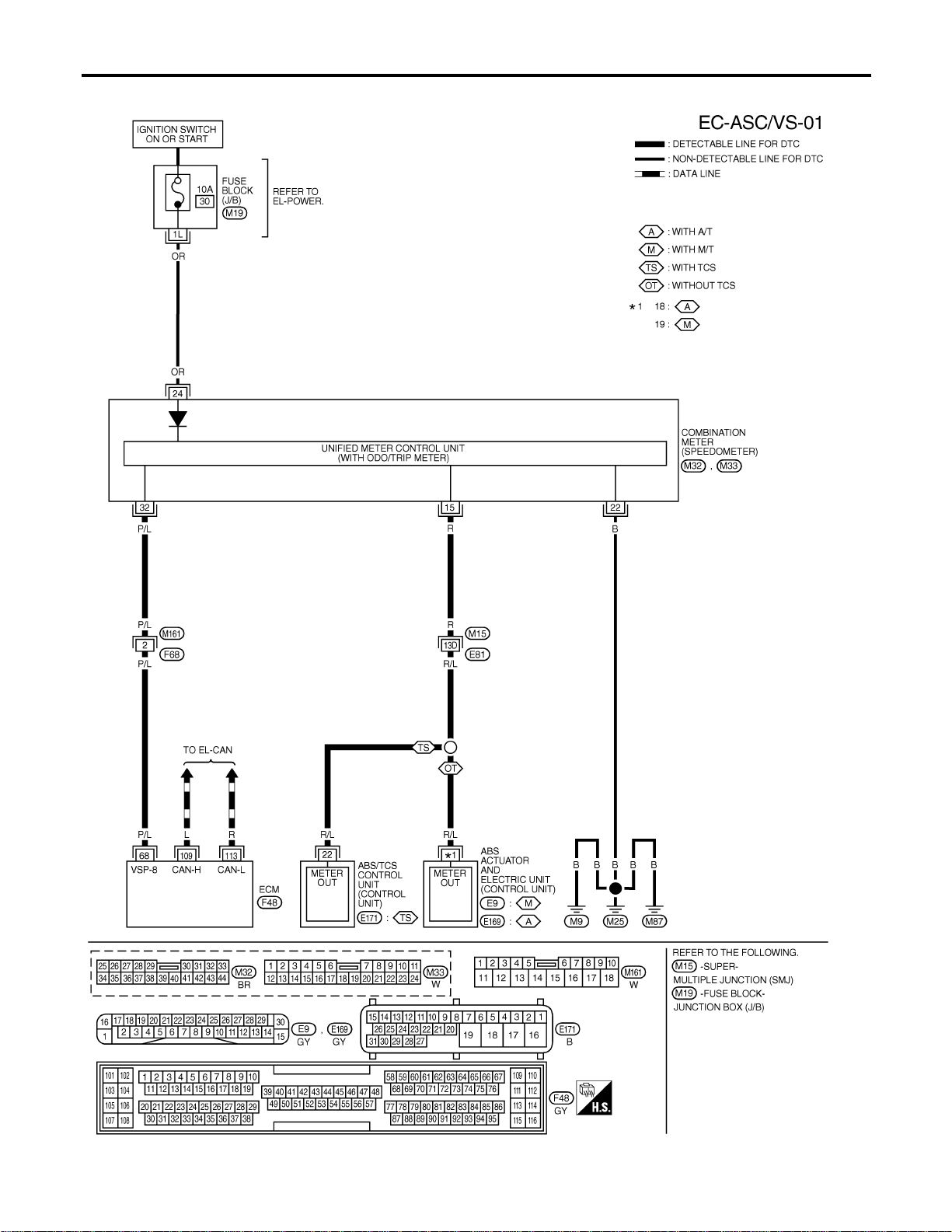
Wiring Diagram
NFEC1229
MEC928D
DTC P1574 ASCD VEHICLE SPEED SENSOR
Wiring Diagram
EC-664
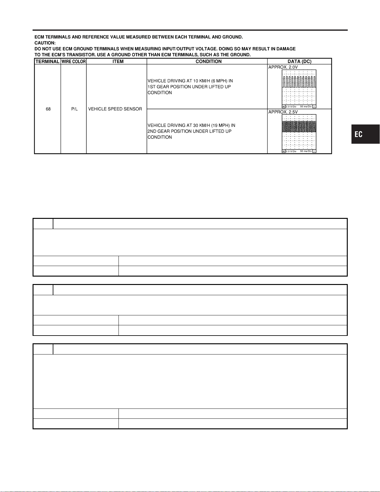
SEC045D
Diagnostic Procedure
NFEC1230
1 CHECK TCM FUNCTION
Check malfunction of the AT system with CONSULT-II or “O/D OFF” indicator.
Refer to AT-5.
OK or NG
OK © GO TO 2.
NG © Check AT system. Refer to AT-5.
2 CHECK SPEEDOMETER OPERATION
Check if speedometer operates normally.
OK or NG
OK © GO TO 3.
NG © Check speedometer and vehicle speed sensor circuit. Refer to EL-117.
3 CHECK VEHICLE SPEED SENSOR INPUT SIGNAL CIRCUIT FOR OPEN AND SHORT
1. Turn ignition switch “OFF”.
2. Disconnect ECM harness connector and combination meter harness connector.
3. Check harness continuity between ECM terminal 68 and combination meter terminal 32 with CONSULT-II or tester.
Refer to Wiring Diagram.
Continuity should exist.
4. Also check harness for short to ground and short to power.
OK or NG
OK © GO TO 5.
NG © GO TO 4.
GI
MA
EM
LC
FE
CL
MT
AT
AX
SU
BR
ST
RS
BT
HA
SC
EL
IDX
DTC P1574 ASCD VEHICLE SPEED SENSOR
Wiring Diagram (Cont’d)
EC-665
4 DETECT MALFUNCTIONING PART
Check the following.
I Harness connectors F68, M161
I Harness for open or short between combination meter and ECM
© Repair open circuit or short to ground or short to power in harness or connectors.
5 CHECK INTERMITTENT INCIDENT
Refer to “TROUBLE DIAGNOSIS FOR INTERMITTENT INCIDENT”, EC-156.
© INSPECTION END
DTC P1574 ASCD VEHICLE SPEED SENSOR
Diagnostic Procedure (Cont’d)
EC-666
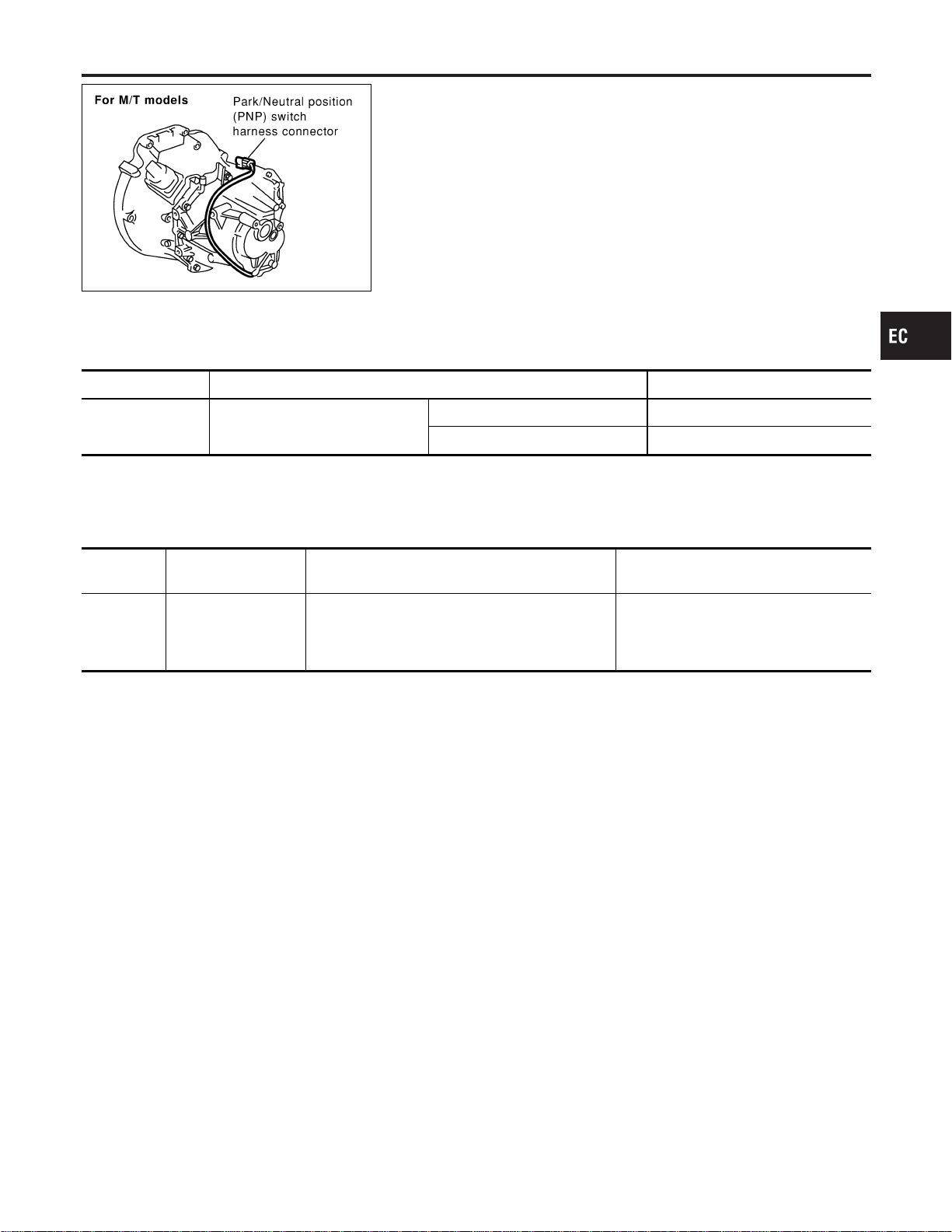
SEC067D
Component Description
NFEC1134
When the gear position is “P” (A/T models only) or “N”, park/neutral
position (PNP) switch is “ON”.
ECM detects the position because the continuity of the line (the
“ON” signal) exists.
For A/T models, the park/neutral position (PNP) switch assembly
also includes a transmission range switch to detect selector lever
position.
CONSULT-II Reference Value in Data Monitor
Mode
NFEC1135
Specification data are reference values.
MONITOR ITEM CONDITION SPECIFICATION
P/N POSI SW I Ignition switch: ON
Shift lever: “P” or “N” ON
Except above OFF
On Board Diagnosis Logic
NFEC1137
DTC No.
Trouble diagnosis
name
DTC Detecting Condition Possible Cause
P1706
1706
Park/Neutral position
switch
The signal of the park/neutral position (PNP)
switch is not changed in the process of engine
starting and driving.
I Harness or connectors
[The park/neutral position (PNP)
switch circuit is open or shorted.]
I Park/neutral position (PNP) switch
DTC Confirmation Procedure
NFEC1138
CAUTION:
Always drive vehicle at a safe speed.
NOTE:
If “DTC Confirmation Procedure” has been previously conducted,
always turn ignition switch “OFF” and wait at least 10 seconds
before conducting the next test.
GI
MA
EM
LC
FE
CL
MT
AT
AX
SU
BR
ST
RS
BT
HA
SC
EL
IDX
DTC P1706 PNP SWITCH
Component Description
EC-667
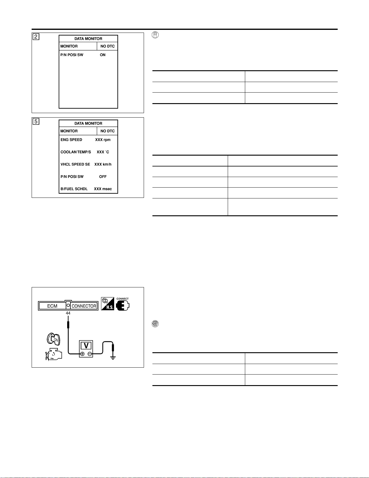
SEF212Y
SEF213Y
WITH CONSULT-II
=NFEC1138S01
1) Turn ignition switch “ON”.
2) Select “P/N POSI SW” in “DATA MONITOR” mode with CON-
SULT-II. Then check the “P/N POSI SW” signal under the fol-
lowing conditions.
Position (Selector lever) Known-good signal
“N” and “P” position ON
Except the above position OFF
If NG, go to “Diagnostic Procedure”, EC-670.
If OK, go to following step.
3) Select “DATA MONITOR” mode with CONSULT-II.
4) Start engine and warm it up to normal operating temperature.
5) Maintain the following conditions for at least 60 consecutive
seconds.
ENG SPEED More than 1,400 rpm
COOLAN TEMP/S More than 70°C (158°F)
B/FUEL SCHDL More than 2 msec
VHCL SPEED SE More than 65 km/h (40 MPH)
Selector lever Suitable position (A/T models)
6th position (M/T models)
6) If 1st trip DTC is detected, go to “Diagnostic Procedure”,
EC-670.
SEF359X
Overall Function Check
NFEC1139
Use this procedure to check the overall function of the park/neutral
position (PNP) switch circuit. During this check, a 1st trip DTC
might not be confirmed.
WITH GST
NFEC1139S01
1) Turn ignition switch “ON”.
2) Check voltage between ECM terminal 44 and body ground
under the following conditions.
Condition (Gear position) Voltage V (Known-good data)
“P” and “N” position Approx. 0
Except the above position Battery voltage
3) If NG, go to “Diagnostic Procedure”, EC-670.
DTC P1706 PNP SWITCH
DTC Confirmation Procedure (Cont’d)
EC-668
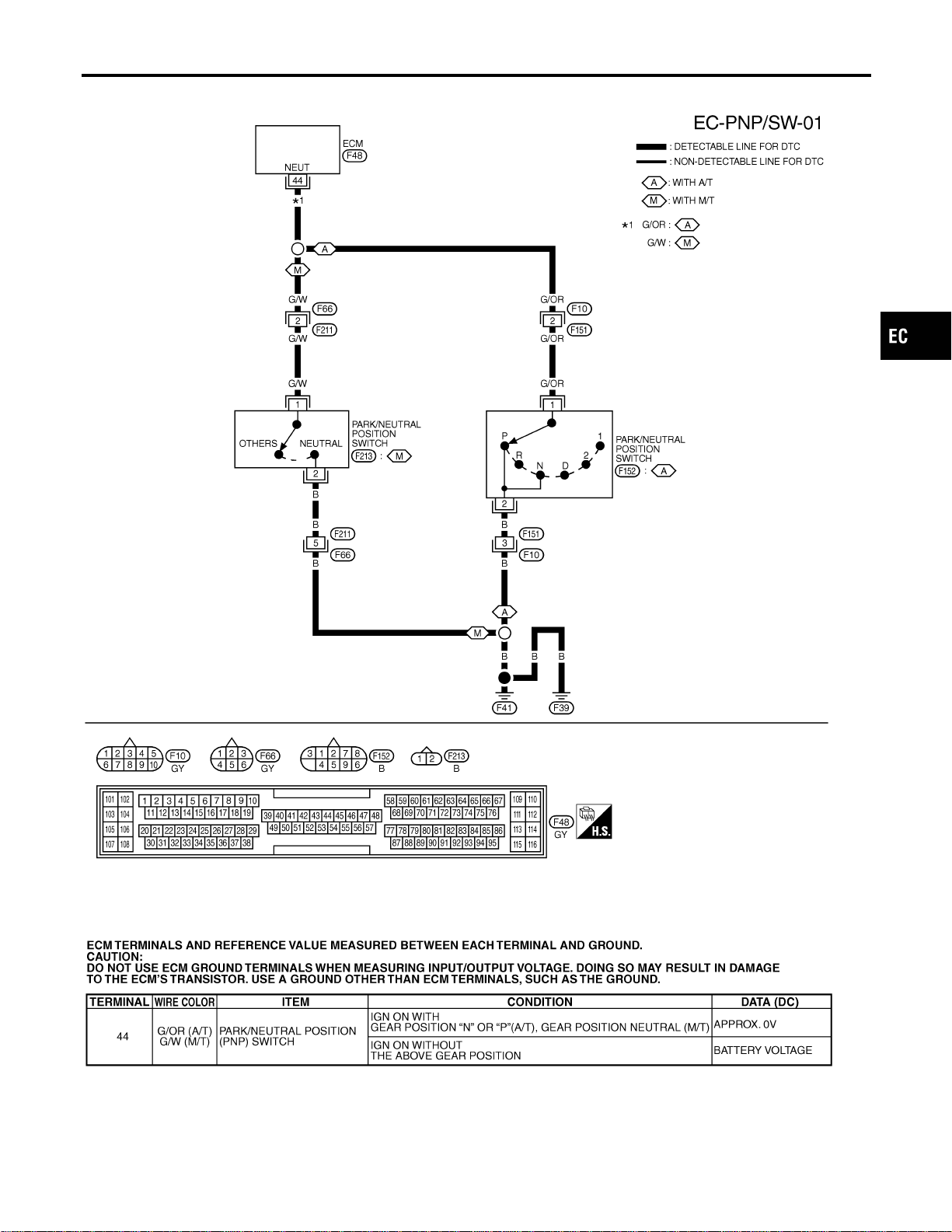
Wiring Diagram
NFEC1140
MEC509D
SEF635XB
GI
MA
EM
LC
FE
CL
MT
AT
AX
SU
BR
ST
RS
BT
HA
SC
EL
IDX
DTC P1706 PNP SWITCH
Wiring Diagram
EC-669
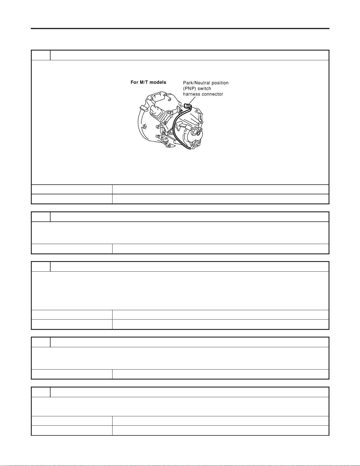
Diagnostic Procedure
NFEC1141
FOR M/T MODELS
NFEC1141S01
1 CHECK PNP SWITCH GROUND CIRCUIT FOR OPEN AND SHORT
1. Turn ignition switch “OFF”.
2. Disconnect park/neutral position (PNP) switch harness connector.
SEC067D
3. Check harness continuity between PNP switch terminal 2 and engine ground. Refer to Wiring Diagram.
Continuity should exist.
4. Also check harness for short to power.
OK or NG
OK © GO TO 3.
NG © GO TO 2.
2 DETECT MALFUNCTIONING PART
Check the following.
I Harness connectors F211, F66
I Harness for open or short between park/neutral position (PNP) switch and ground
© Repair open circuit or short to power in harness or connectors.
3 CHECK PNP SWITCH INPUT SIGNAL CIRCUIT FOR OPEN AND SHORT
1. Disconnect ECM harness connector.
2. Check harness continuity between ECM terminal 44 and PNP switch terminal 1. Refer to Wiring Diagram.
Continuity should exist.
3. Also check harness for short to ground and short to power.
OK or NG
OK © GO TO 5.
NG © GO TO 4.
4 DETECT MALFUNCTIONING PART
Check the following.
I Harness connectors F66, F211
I Harness for open or short between park/neutral position (PNP) switch and ECM
© Repair open circuit or short to ground or short to power in harness or connectors.
5 CHECK PARK/NEUTRAL POSITION (PNP) SWITCH
Refer to MT section, “Position Switch Check”.
OK or NG
OK © GO TO 6.
NG © Replace park/neutral position (PNP) switch.
DTC P1706 PNP SWITCH
Diagnostic Procedure
EC-670
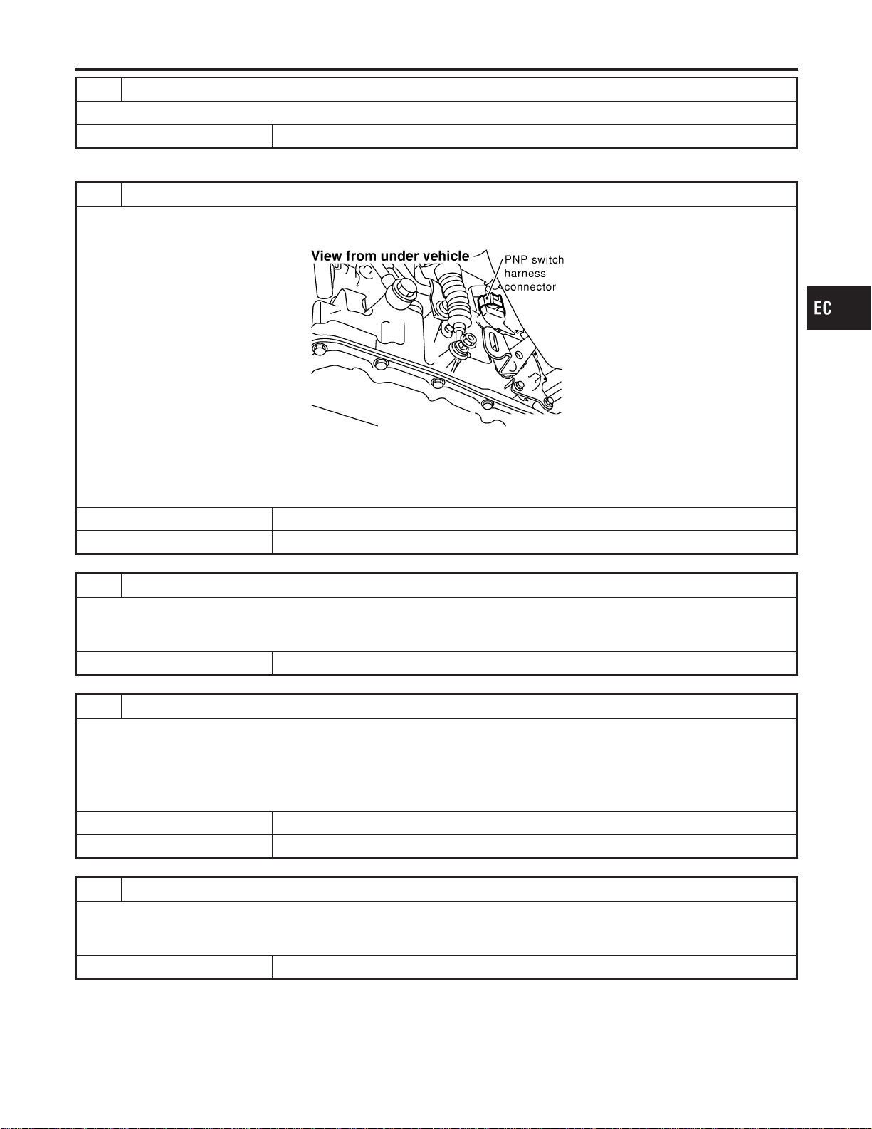
6 CHECK INTERMITTENT INCIDENT
Refer to “TROUBLE DIAGNOSIS FOR INTERMITTENT INCIDENT”, EC-156.
© INSPECTION END
FOR A/T MODELS
NFEC1141S02
1 CHECK PNP SWITCH GROUND CIRCUIT FOR OPEN AND SHORT
1. Turn ignition switch “OFF”.
2. Disconnect park/neutral position (PNP) switch harness connector.
SEF279X
3. Check harness continuity between PNP switch terminal 2 and engine ground. Refer to Wiring Diagram.
Continuity should exist.
4. Also check harness for short to power.
OK or NG
OK © GO TO 3.
NG © GO TO 2.
2 DETECT MALFUNCTIONING PART
Check the following.
I Harness connectors F151, F10
I Check harness for open between park/neutral position (PNP) switch and engine ground.
© Repair open circuit or short to power in harness or connectors.
3 CHECK PNP SWITCH INPUT SIGNAL CIRCUIT FOR OPEN AND SHORT
1. Disconnect ECM harness connector.
2. Check harness continuity between ECM terminal 44 and PNP switch terminal 1. Refer to Wiring Diagram.
Continuity should exist.
3. Also check harness for short to ground and short to power.
OK or NG
OK © GO TO 5.
NG © GO TO 4.
4 DETECT MALFUNCTIONING PART
Check the following.
I Harness connectors F10, F151
I Harness for open or short between ECM and park/neutral position (PNP) switch
© Repair open circuit or short to ground or short to power in harness or connectors.
GI
MA
EM
LC
FE
CL
MT
AT
AX
SU
BR
ST
RS
BT
HA
SC
EL
IDX
DTC P1706 PNP SWITCH
Diagnostic Procedure (Cont’d)
EC-671
5 CHECK PARK/NEUTRAL POSITION (PNP) SWITCH
Refer to AT-107, “Diagnostic Procedure”.
OK or NG
OK © GO TO 6.
NG © Replace park/neutral position (PNP) switch.
6 CHECK INTERMITTENT INCIDENT
Refer to “TROUBLE DIGNOSIS FOR INTERMITTENT INCIDENT”, EC-156.
© INSPECTION END
DTC P1706 PNP SWITCH
Diagnostic Procedure (Cont’d)
EC-672
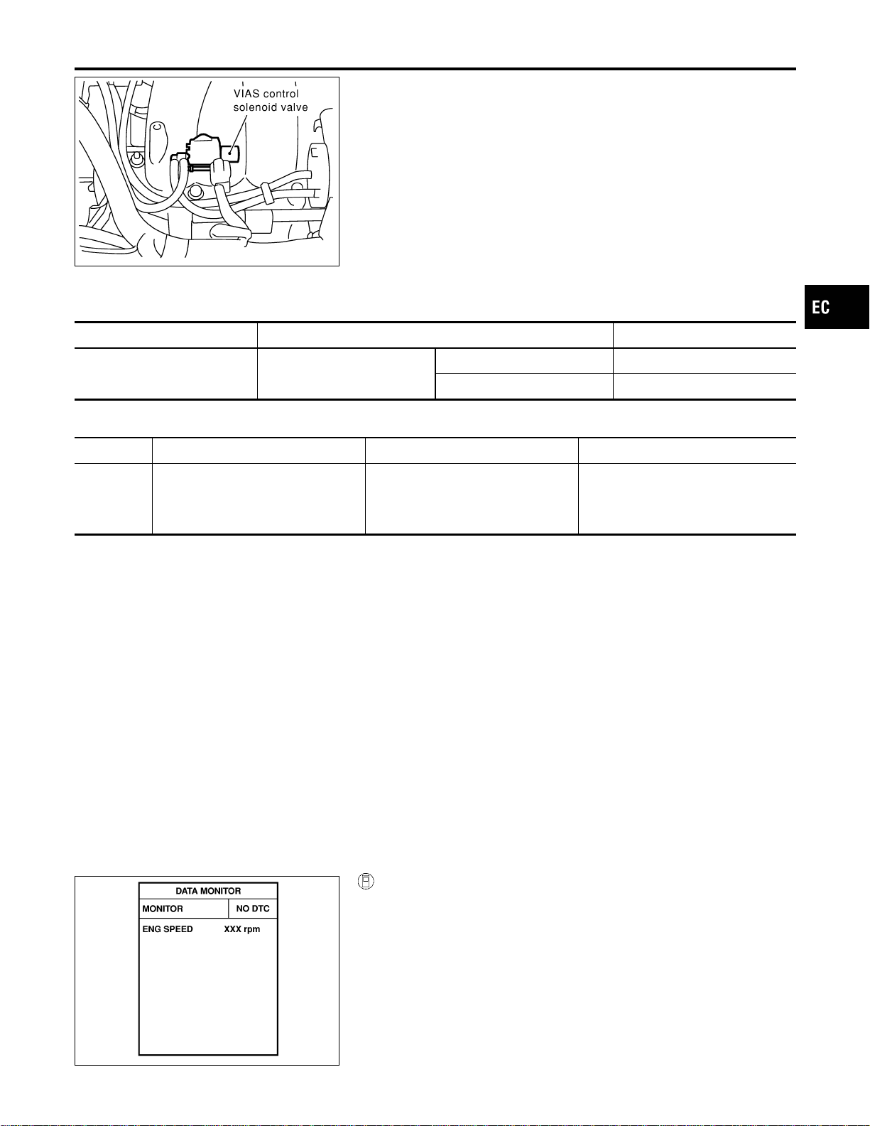
SEC058D
Component Description
NFEC1400
The VIAS control solenoid valve cuts the intake manifold vacuum
signal for power valve control. It responds to ON/OFF signals from
the ECM. When the solenoid is off, the vacuum signal from the
intake manifold is cut. When the ECM sends an ON signal the coil
pulls the plunger downward and feeds the vacuum signal to the
power valve actuator.
CONSULT-II Reference Value in Data Monitor
Mode
NFEC1404
MONITOR ITEM CONDITION SPECIFICATION
VIAS S/V I Engine: After warning up
1,800 - 3,600 rpm ON
Except above condition OFF
On Board Diagnosis Logic
NFEC1472
DTC No. Trouble diagnosis name DTC Detecting Condition Possible Cause
P1800
1800
VIAS control solenoid valve circuit
open
An improper voltage signal is sent to
ECM through VIAS control solenoid
valve.
I Harness connectors
(The solenoid valve circuit is open
or shorted.)
I VIAS control solenoid valve
DTC Confirmation Procedure
NFEC1473
NOTE:
If “DTC” Confirmation Procedure” has been previously conducted,
always turn ignition switch “OFF” and wait at least 10 seconds
before conducting the next test.
TESTING CONDITION:
Before performing the following procedure, confirm battery
voltage is more than 11V at idle.
SEF058Y
WITH CONSULT-II
1. Turn ignition switch “ON”.
2. Select “DATA MONITOR” mode with CONSULT-II.
3. Start engine and let it for 10 seconds.
4. If 1st trip DTC is detected, go to “Diagnostic Procedure”,
EC-676.
GI
MA
EM
LC
FE
CL
MT
AT
AX
SU
BR
ST
RS
BT
HA
SC
EL
IDX
DTC P1800 VIAS CONTROL SOLENOID VALVE
Component Description
EC-673

WITH GST
Follow the procedure “WITH CONSULT-II” above.
DTC P1800 VIAS CONTROL SOLENOID VALVE
DTC Confirmation Procedure (Cont’d)
EC-674
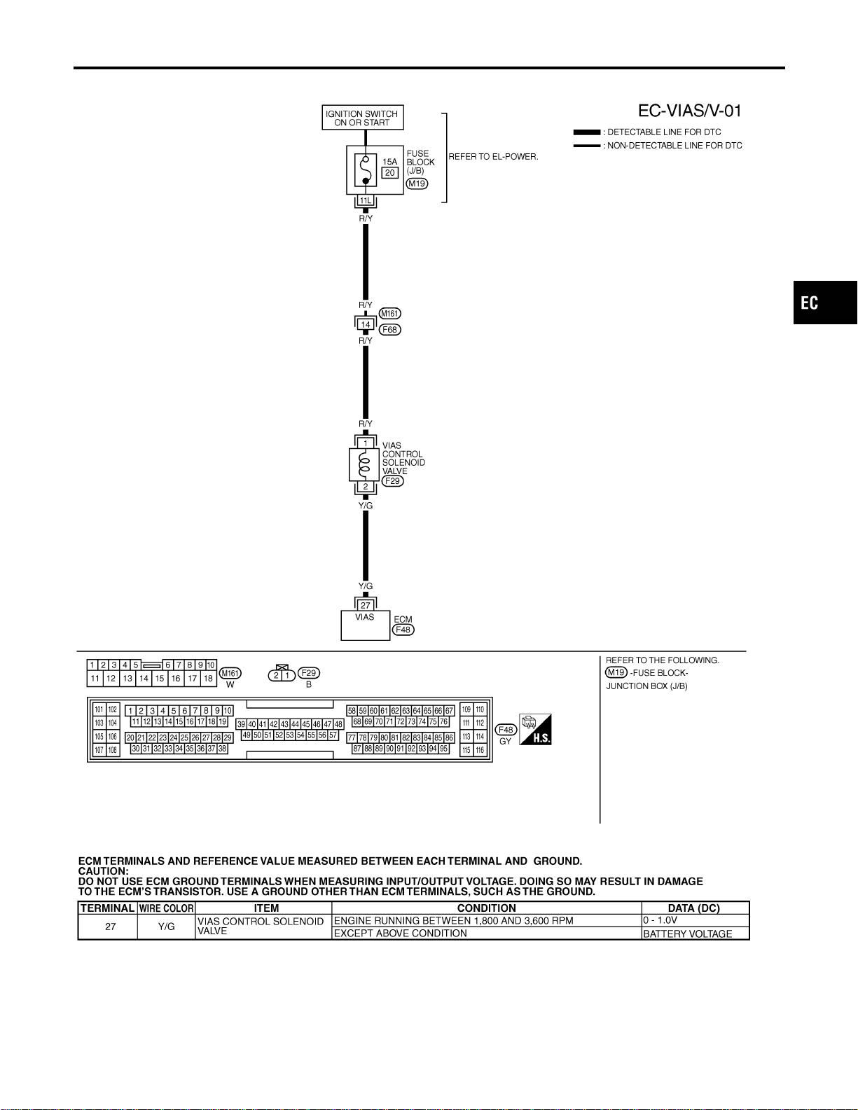
Wiring Diagram
=NFEC1402
MEC511D
SEF636XC
GI
MA
EM
LC
FE
CL
MT
AT
AX
SU
BR
ST
RS
BT
HA
SC
EL
IDX
DTC P1800 VIAS CONTROL SOLENOID VALVE
Wiring Diagram
EC-675
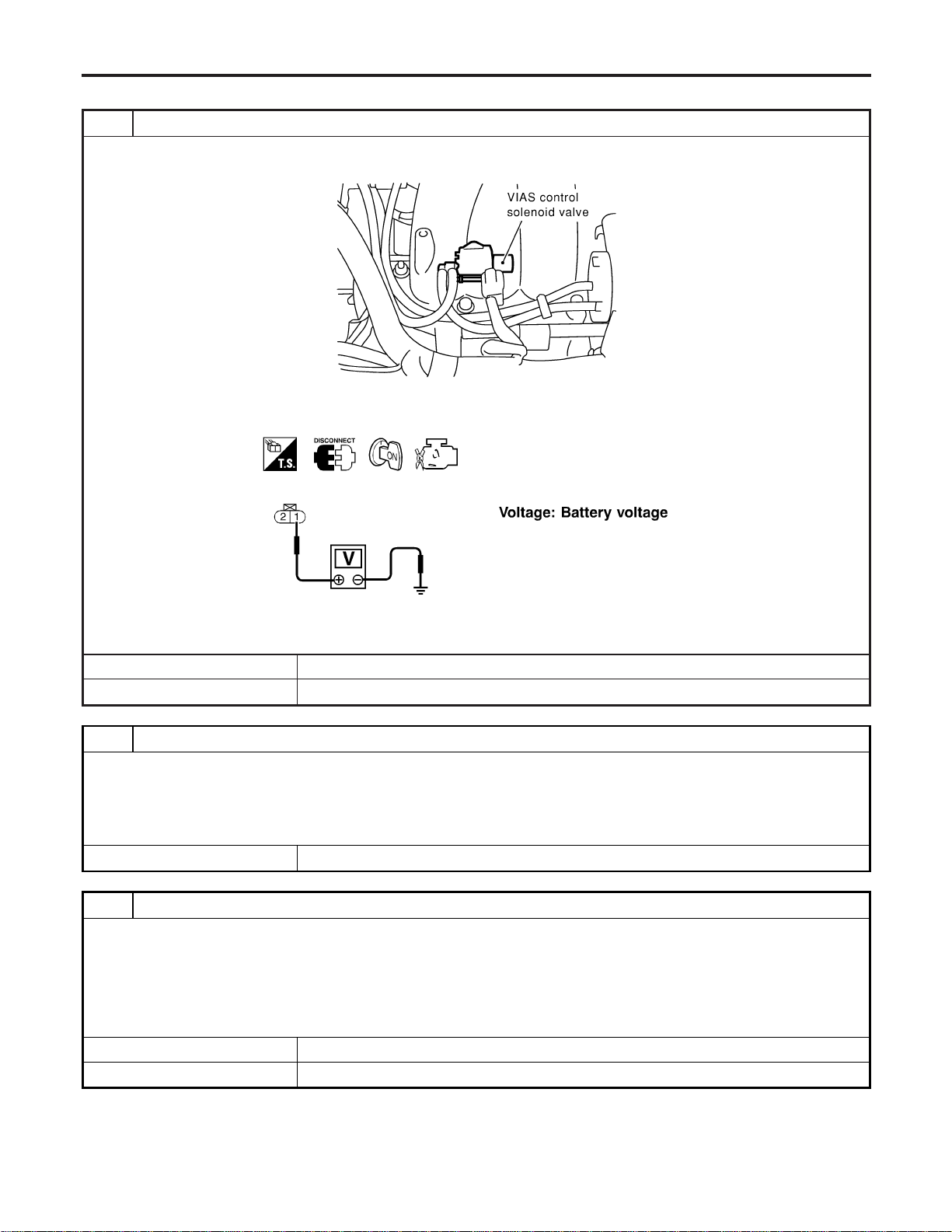
Diagnostic Procedure
NFEC1403
1 CHECK VIAS CONTROL SOLENOID VALVE POWER SUPPLY CIRCUIT
1. Turn ignition switch “OFF”.
2. Disconnect VIAS control solenoid valve harness connector.
SEC058D
3. Turn ignition switch “ON”.
4. Check voltage between terminal 1 and ground with CONSULT-II or tester.
SEF603X
OK or NG
OK © GO TO 3.
NG © GO TO 2.
2 DETECT MALFUNCTIONING PART
Check the following.
I Harness connectors M161, F68
I Fuse block (J/B) connector M19
I 15A fuse
I Harness continuity between fuse and VIAS control solenoid valve
© Repair harness or connectors.
3 CHECK VIAS CONTROL SOLENOID VALVE OUTPUT SIGNAL CIRCUIT FOR OPEN AND SHORT
1. Turn ignition switch “OFF”.
2. Disconnect ECM harness connector.
3. Check harness continuity between ECM terminal 27 and terminal 2. Refer to Wiring Diagram.
Continuity should exist.
4. Also check harness for short to ground and short to power.
OK or NG
OK © GO TO 4.
NG © Repair open circuit or short to ground or short to power in harness or connectors.
DTC P1800 VIAS CONTROL SOLENOID VALVE
Diagnostic Procedure
EC-676
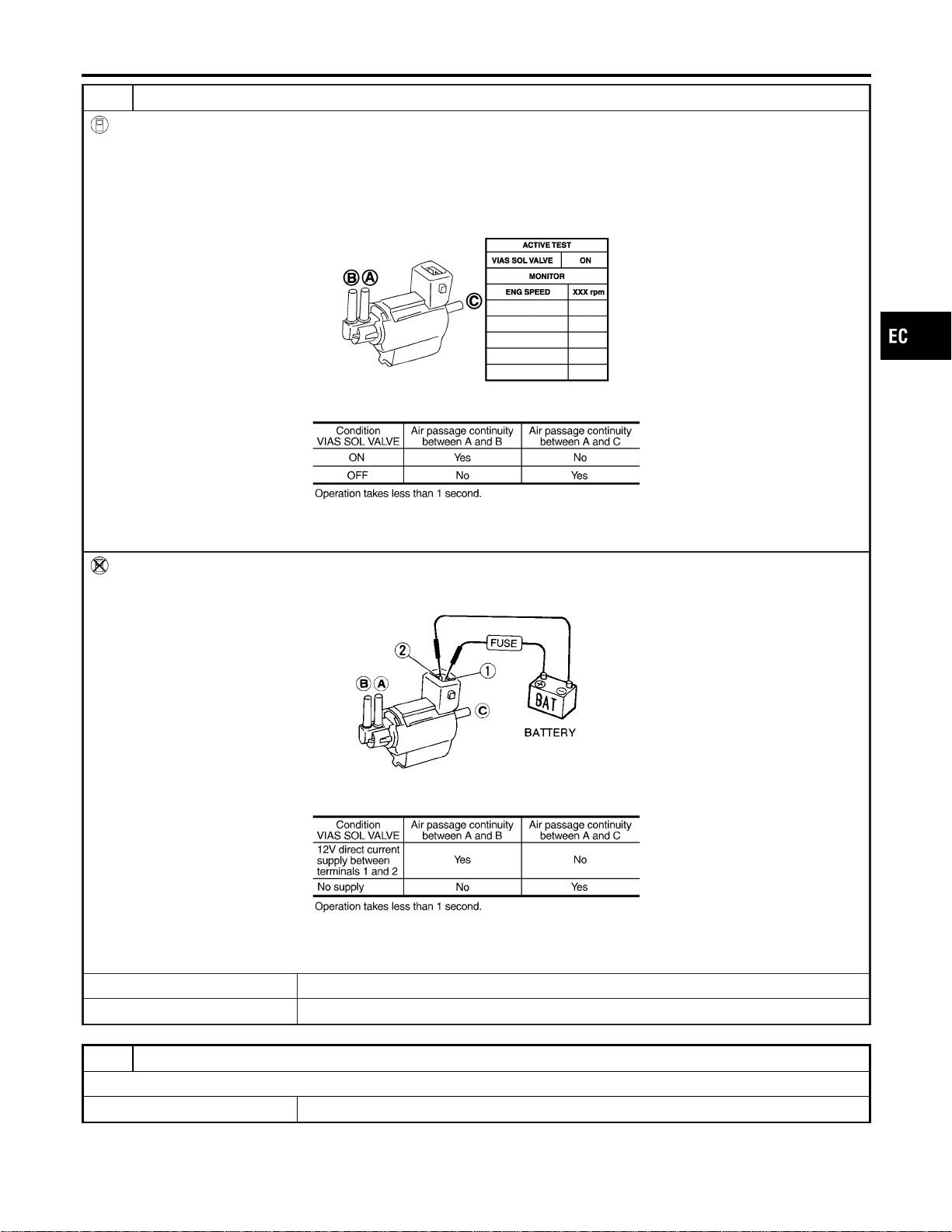
4 CHECK VIAS CONTROL SOLENOID VALVE
With CONSULT-II
1. Reconnect harness connector disconnected.
2. Turn ignition switch ON.
3. Perform “VIAS SOL VALVE” in “ACTIVE TEST” mode.
4. Check air passage continuity and operation delay time under the following conditions.
PBIB0177E
MTBL1301
Without CONSULT-II
Check air passage continuity and operation delay time under the following conditions.
MEC488B
MTBL1302
OK or NG
OK © GO TO 5.
NG © Replace VIAS control solenoid valve.
5 CHECK INTERMITTENT INCIDENT
Refer to “TROUBLE DIAGNOSIS FOR INTERMITTENT INCIDENT”, EC-156.
© INSPECTION END
GI
MA
EM
LC
FE
CL
MT
AT
AX
SU
BR
ST
RS
BT
HA
SC
EL
IDX
DTC P1800 VIAS CONTROL SOLENOID VALVE
Diagnostic Procedure (Cont’d)
EC-677
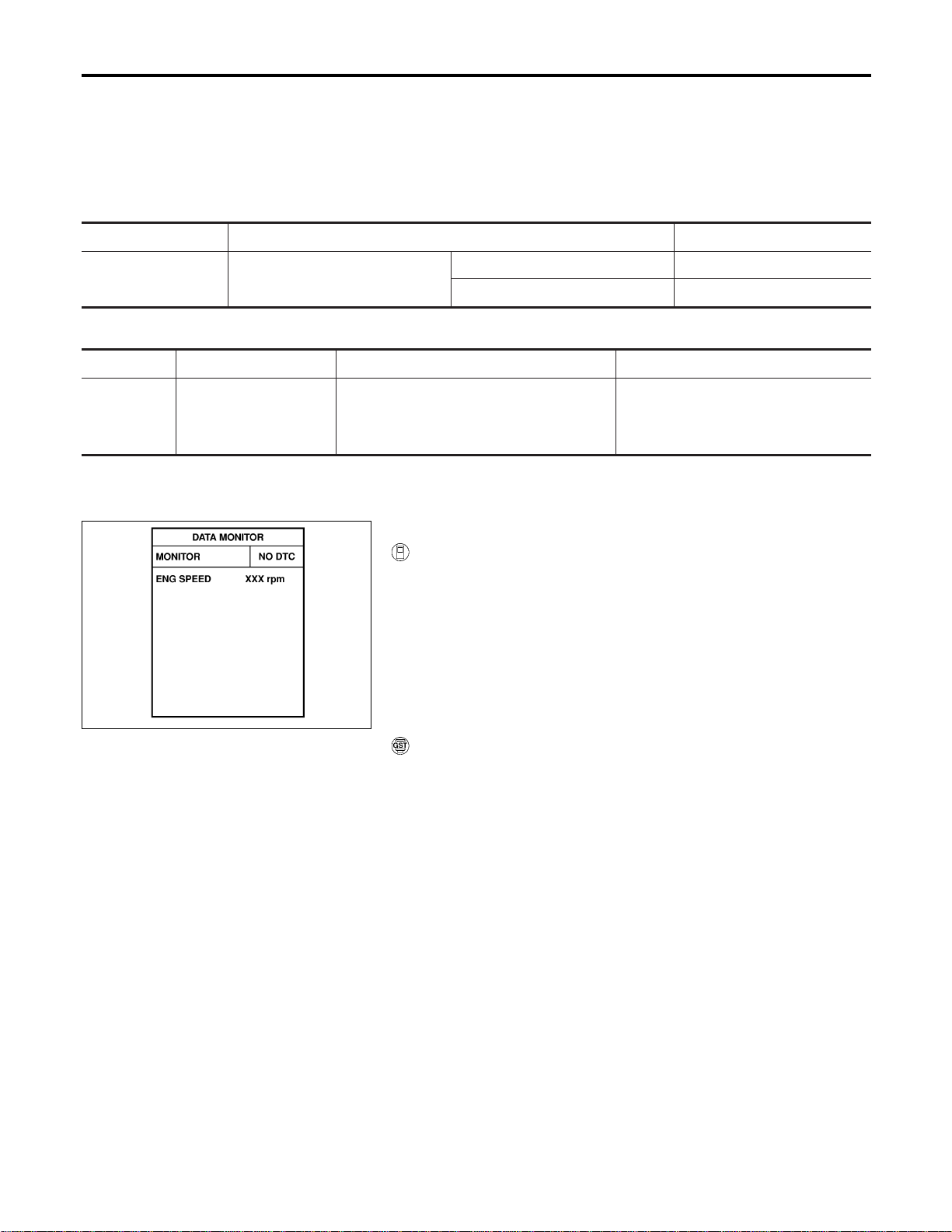
Description
NFEC1278
Brake switch signal is applied to the ECM through the stop lamp switch when the brake pedal is depressed.
This signal is used mainly to decrease the engine speed when the vehicle is driving.
CONSULT-II Reference Value in Data Monitor
Mode
NFEC1279
Specification data are reference values.
MONITOR ITEM CONDITION SPECIFICATION
BRAKE SW I Ignition switch: ON
Brake pedal: Fully released OFF
Brake pedal: Slightly depressed ON
On Board Diagnosis Logic
NFEC1280
DTC No. Trouble diagnosis name DTC detecting condition Possible cause
P1805
1805
Brake switch
A brake switch signal is not sent to ECM for
an extremely long time while the vehicle is
driving.
I Harness or connectors
(Stop lamp switch circuit is open or
shorted.)
I Stop lamp switch
SEF058Y
DTC Confirmation Procedure
NFEC1281
WITH CONSULT-II
1. Turn ignition switch “ON”.
2. Fully depress the brake pedal for at least 5 seconds.
3. Erase the DTC with CONSULT-II.
4. Select “DATA MONITOR” mode with CONSULT-II.
5. If 1st trip DTC is detected, go to “Diagnostic Procedure”,
EC-680.
WITH GST
Follow the procedure “WITH CONSULT-II” above.
DTC P1805 BRAKE SWITCH
Description
EC-678
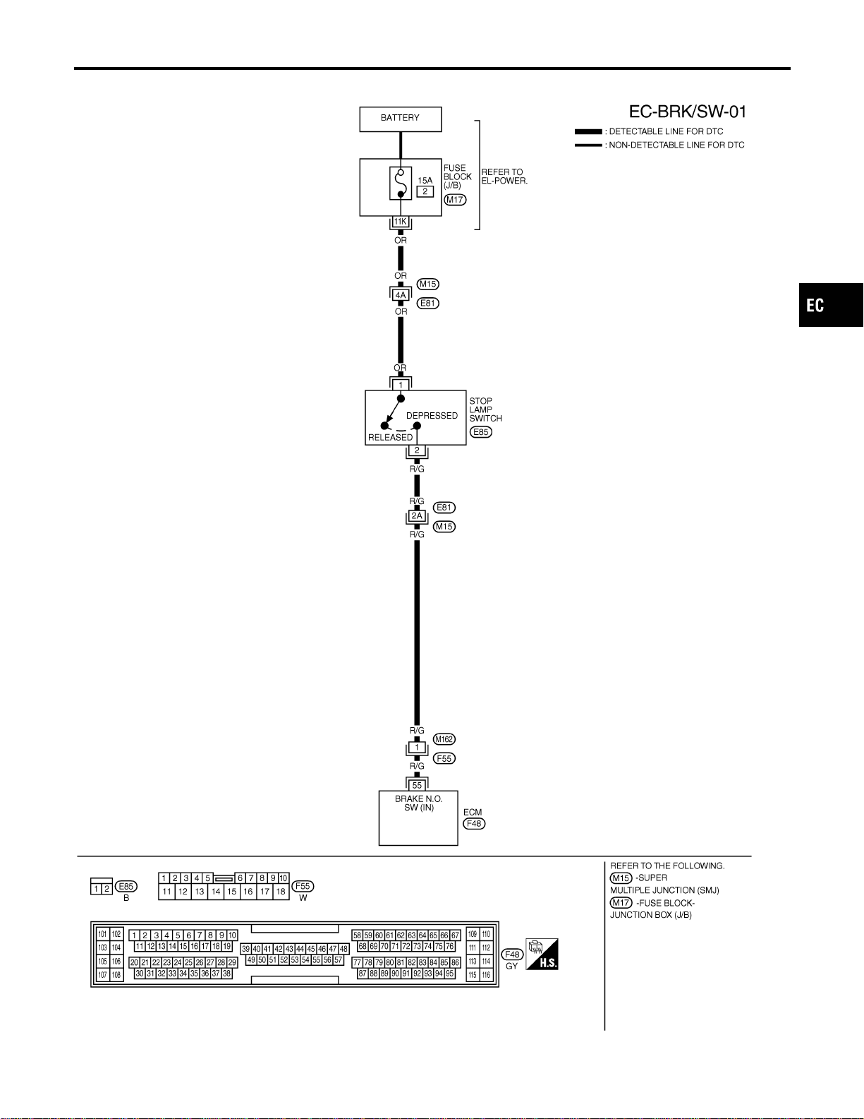
Wiring Diagram
NFEC1282
MEC822D
GI
MA
EM
LC
FE
CL
MT
AT
AX
SU
BR
ST
RS
BT
HA
SC
EL
IDX
DTC P1805 BRAKE SWITCH
Wiring Diagram
EC-679
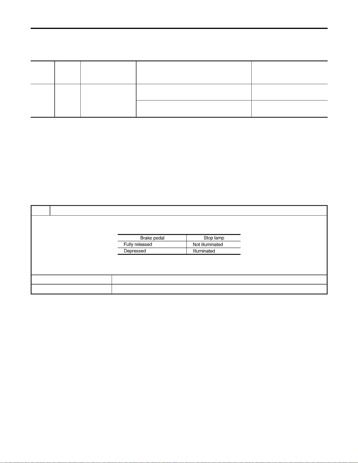
Specification data are reference values and are measured between each terminal and body ground.
CAUTION:
Do not use ECM ground terminals when measuring input/output voltage. Doing so may result in dam-
age to the ECM’s transistor. Use a ground other than ECM terminals, such as the ground.
TER-
MINAL
NO.
WIRE
COLOR
ITEM CONDITION DATA (DC Voltage)
55 R/G Stop lamp switch
[Engine is running]
I Brake pedal fully released
Approximately 0V
[Engine is running]
I Brake pedal fully depressed
BATTERY VOLTAGE
(11 - 14V)
Diagnostic Procedure
NFEC1283
1 CHECK STOP LAMP SWITCH CIRCUIT
1. Turn ignition switch “OFF”.
2. Check the stop lamp when depressing and releasing the brake pedal.
MTBL1138
OK or NG
OK © GO TO 4.
NG © GO TO 2.
DTC P1805 BRAKE SWITCH
Wiring Diagram (Cont’d)
EC-680
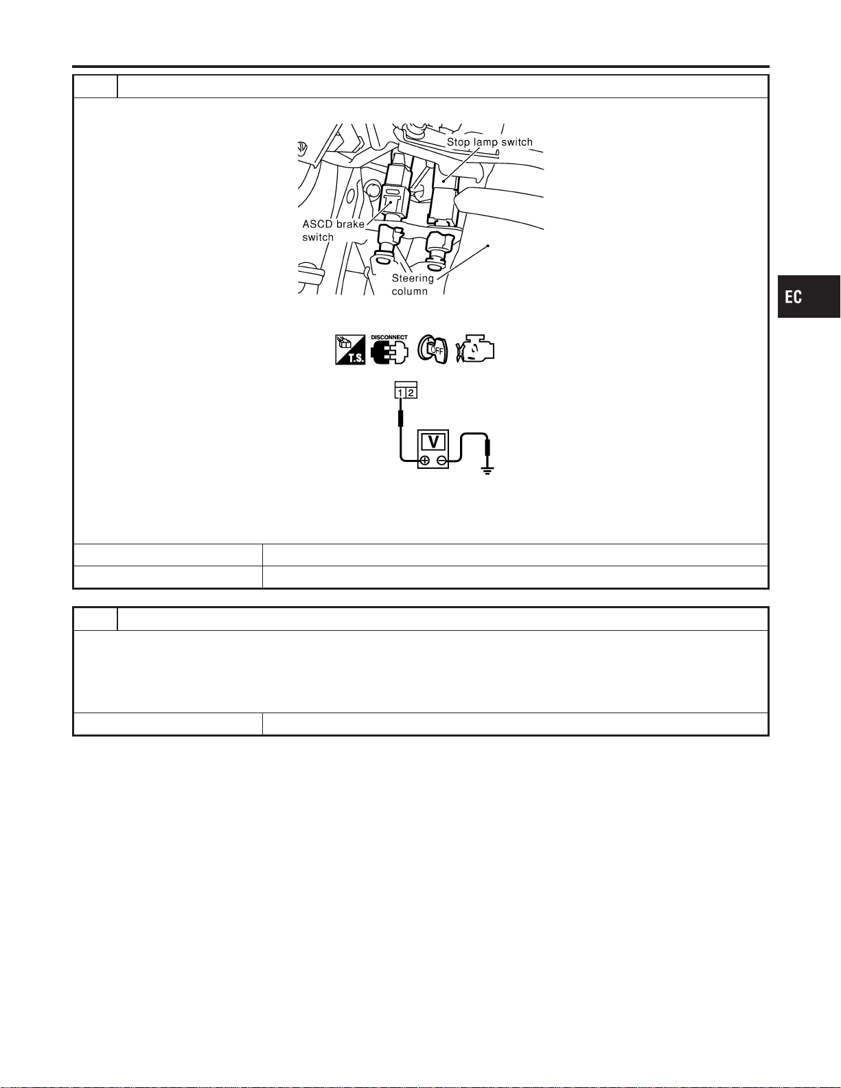
2 CHECK STOP LAMP SWITCH POWER SUPPLY CIRCUIT
1. Disconnect stop lamp switch harness connector.
SEC053D
2. Check voltage between stop lamp switch terminal 1 and ground with CONSULT-II or tester.
SEC051D
Voltage: Battery voltage
OK or NG
OK © GO TO 4.
NG © GO TO 3.
3 DETECT MALFUNCTIONING PART
Check the following.
I Harness connectors M15, E81
I 15A fuse
I Fuse block (J/B) connector M17
I Harness for open and short between stop lamp switch and battery
© Repair open circuit or short to ground or short to power in harness or connectors.
GI
MA
EM
LC
FE
CL
MT
AT
AX
SU
BR
ST
RS
BT
HA
SC
EL
IDX
DTC P1805 BRAKE SWITCH
Diagnostic Procedure (Cont’d)
EC-681
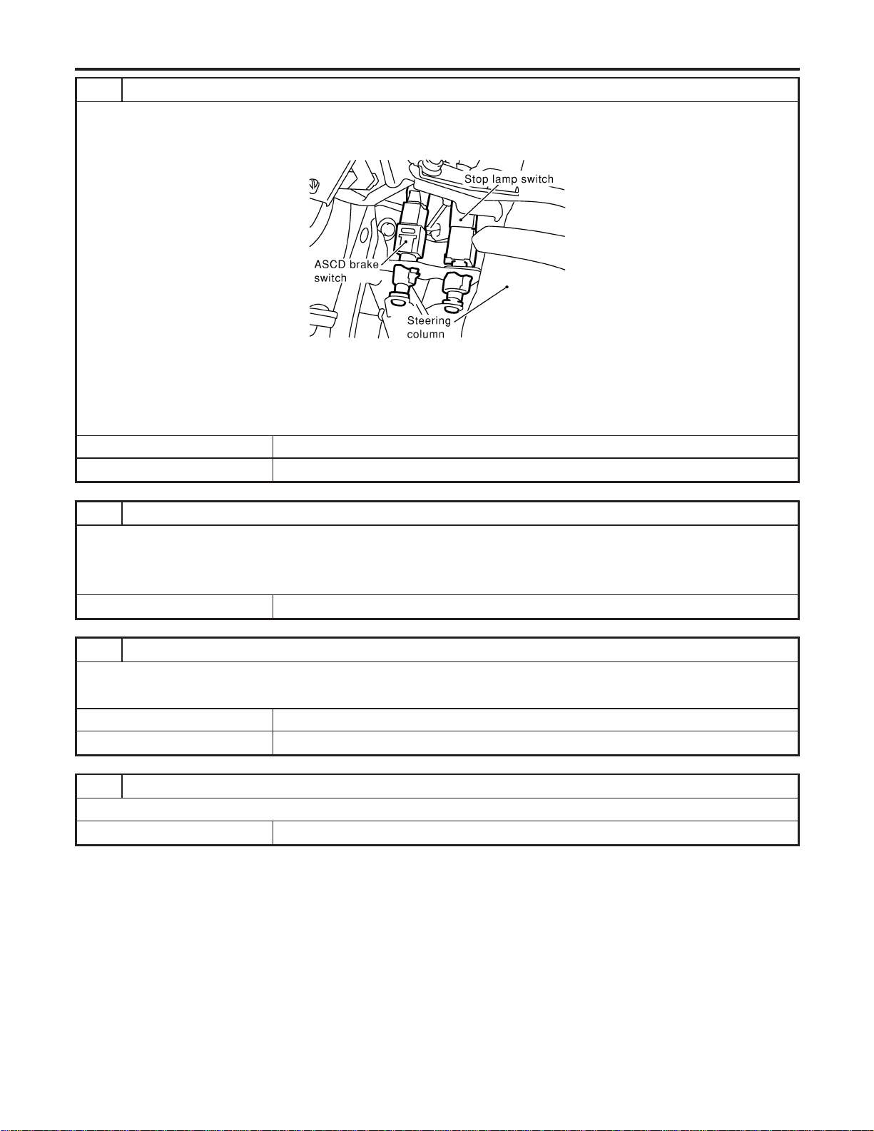
4 CHECK STOP LAMP SWITCH INPUT SIGNAL CIRCUIT FOR OPEN AND SHORT
1. Turn ignition switch “OFF”.
2. Disconnect ECM harness connector.
3. Disconnect stop lamp switch harness connector.
SEC053D
4. Check harness continuity between ECM terminal 55 and stop lamp switch terminal 2.
Refer to Wiring Diagram.
Continuity should exist.
5. Also check harness for short to ground and short to power.
OK or NG
OK © GO TO 6.
NG © GO TO 5.
5 DETECT MALFUNCTIONING PART
Check the following.
I Harness connectors E81, M15
I Harness connectors M162, F55
I Harness for open or short between ECM and stop lamp switch
© Repair open circuit or short to ground or short to power in harness or connectors.
6 CHECK STOP LAMP SWITCH
Refer to “Component Inspection”, EC-683.
OK or NG
OK © GO TO 7.
NG © Replace stop lamp switch.
7 CHECK INTERMITTENT INCIDENT
Refer to “TROUBLE DIAGNOSIS FOR INTERMITTENT INCIDENT”, EC-156.
© INSPECTION END
DTC P1805 BRAKE SWITCH
Diagnostic Procedure (Cont’d)
EC-682
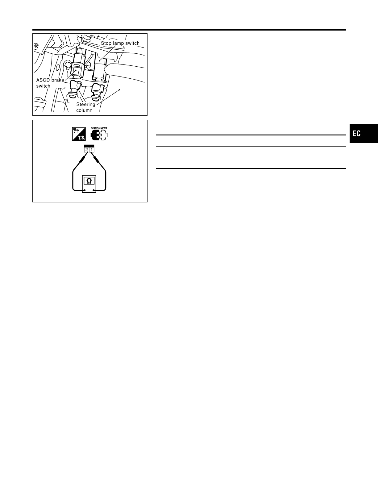
SEC053D
Component Inspection
=NFEC1284
STOP LAMP SWITCH
1. Disconnect stop lamp switch harness connector.
SEC052D
2. Check continuity between stop lamp switch terminals 1 and 2
under the following conditions.
Conditions Continuity
Brake pedal fully released Should not exist.
Brake pedal depressed Should exist.
3. If NG, replace stop lamp switch.
GI
MA
EM
LC
FE
CL
MT
AT
AX
SU
BR
ST
RS
BT
HA
SC
EL
IDX
DTC P1805 BRAKE SWITCH
Component Inspection
EC-683
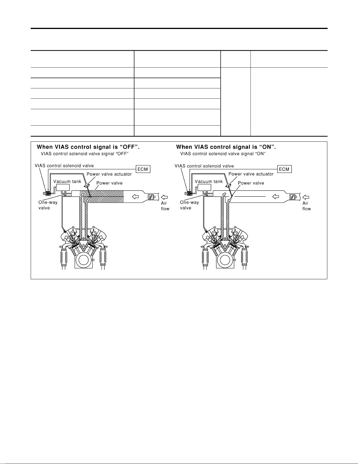
Description
NFEC0596
SYSTEM DESCRIPTION
NFEC0596S01
Sensor Input Signal to ECM
ECM func-
tion
Actuator
Mass air flow sensor Amount of intake air
VIAS con-
trol
VIAS control solenoid valve
Throttle position sensor Throttle position
Accelerator pedal position sensor Accelerator pedal position
Ignition switch Start signal
Crankshaft position sensor (POS)
Camshaft position sensor (PHASE)
Engine speed
Engine coolant temperature sensor Engine coolant temperature
SEC916C
When the engine is running at low or medium speed, the power
valve is fully closed. Under this condition, the effective suction port
length is equivalent to the total length of the intake manifold collec-
tor’s suction port including the intake valve. This long suction port
provides increased air intake which results in improved suction
efficiency and higher torque generation.
The surge tank and one-way valve are provided. When engine is
running at high speed, the ECM sends the signal to the VIAS con-
trol solenoid valve. This signal introduces the intake manifold
vacuum into the power valve actuator and therefore opens the
power valve to two suction passages together in the collector.
Under this condition, the effective port length is equivalent to the
length of the suction port provided independently for each cylinder.
This shortened port length results in enhanced engine output with
reduced suction resistance under high speeds.
VARIABLE INDUCTION AIR CONTROL SYSTEM (VIAS)
Description
EC-684
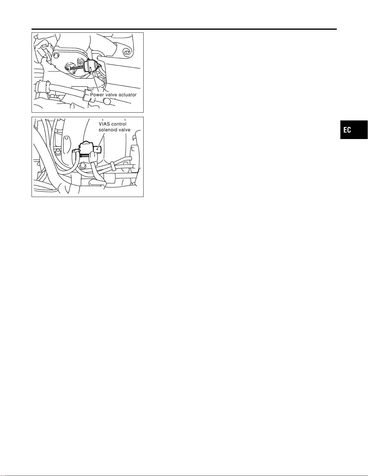
SEC059D
COMPONENT DESCRIPTION
NFEC0596S02
Power Valve
NFEC0596S0201
The power valve is installed in intake manifold collector and used
to control the suction passage of the variable induction air control
system. It is set in the fully closed or fully opened position by the
power valve actuator operated by the vacuum stored in the surge
tank. The vacuum in the surge tank is controlled by the VIAS con-
trol solenoid valve.
SEC058D
VIAS Control Solenoid Valve
NFEC0596S0202
The VIAS control solenoid valve cuts the intake manifold vacuum
signal for power valve control. It responds to ON/OFF signals from
the ECM. When the solenoid is off, the vacuum signal from the
intake manifold is cut. When the ECM sends an ON signal the coil
pulls the plunger downward and feeds the vacuum signal to the
power valve actuator.
GI
MA
EM
LC
FE
CL
MT
AT
AX
SU
BR
ST
RS
BT
HA
SC
EL
IDX
VARIABLE INDUCTION AIR CONTROL SYSTEM (VIAS)
Description (Cont’d)
EC-685
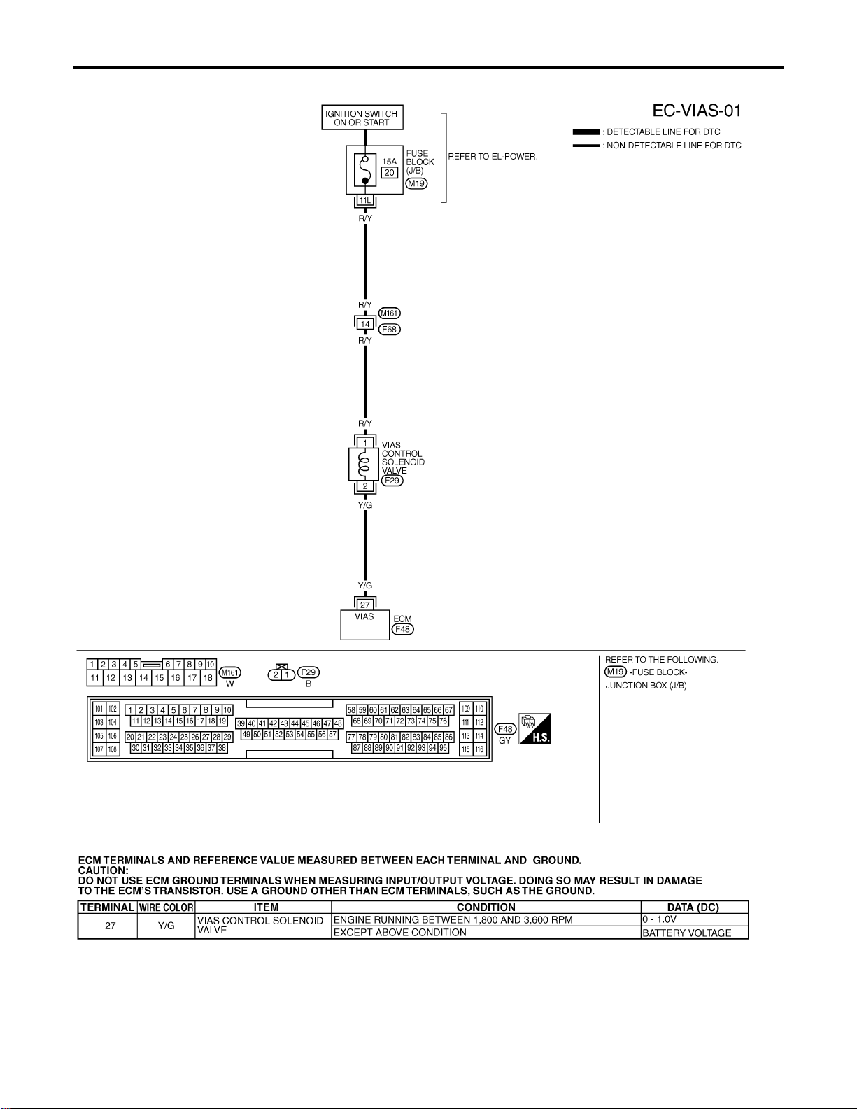
Wiring Diagram
NFEC0597
MEC823D
SEF636XC
VARIABLE INDUCTION AIR CONTROL SYSTEM (VIAS)
Wiring Diagram
EC-686
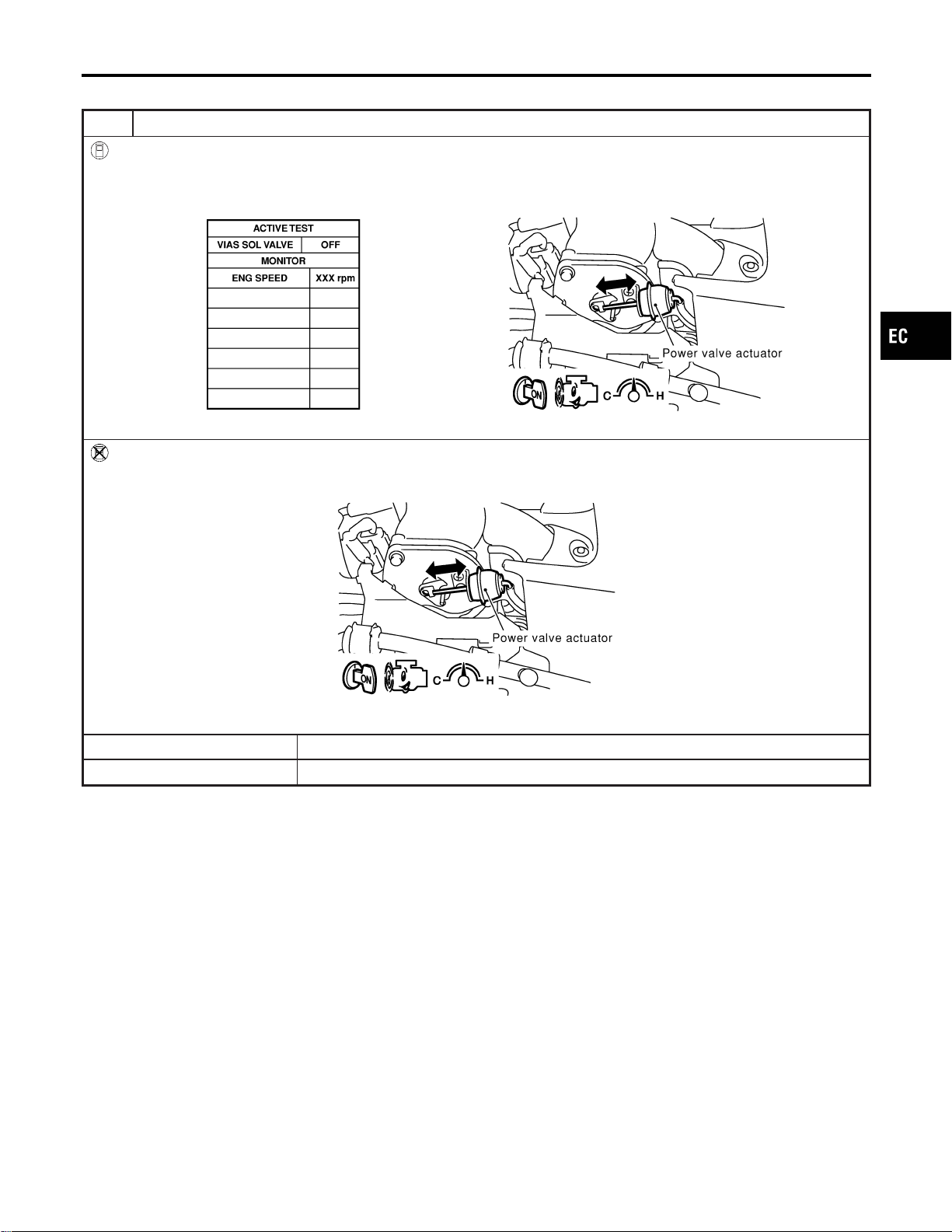
Diagnostic Procedure
NFEC0598
1 CHECK OVERALL FUNCTION
With CONSULT-II
1. Start engine and warm it up to normal operating temperature.
2. Perform “VIAS SOL VALVE” in “ACTIVE TEST” mode with CONSULT-II.
3. Turn VIAS control solenoid valve “ON” and “OFF”, and make sure that power valve actuator rod moves.
SEC128D
Without CONSULT-II
1. Start engine and warm it up to normal operating temperature.
2. Rev engine quickly up to above 5,000 rpm and make sure that power valve actuator rod moves.
SEC060D
OK or NG
OK © INSPECTION END
NG © GO TO 2.
GI
MA
EM
LC
FE
CL
MT
AT
AX
SU
BR
ST
RS
BT
HA
SC
EL
IDX
VARIABLE INDUCTION AIR CONTROL SYSTEM (VIAS)
Diagnostic Procedure
EC-687
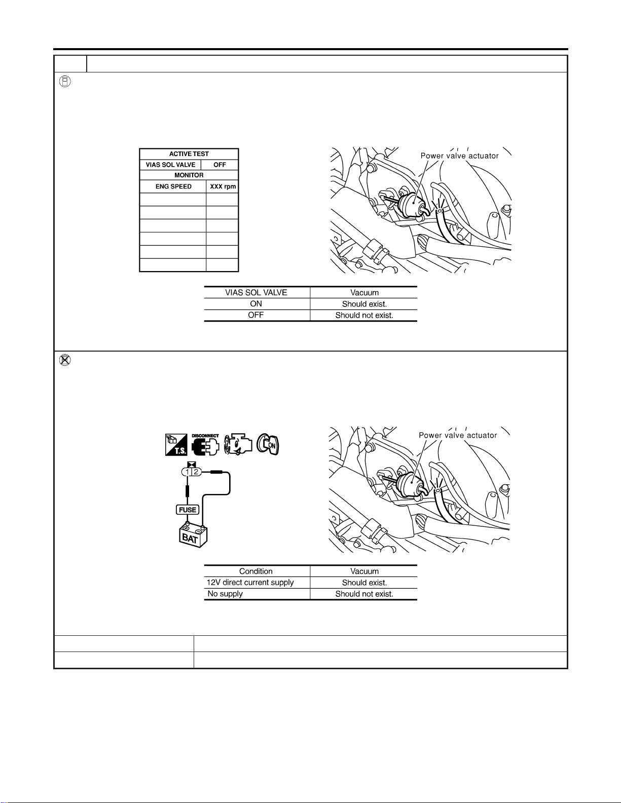
2 CHECK VACUUM EXISTENCE
With CONSULT-II
1. Stop engine and disconnect vacuum hose connected to power valve actuator.
2. Start engine and let it idle.
3. Perform “VIAS SOL VALVE” in “ACTIVE TEST” mode with CONSULT-II.
4. Turn VIAS control solenoid valve “ON” and “OFF”, and check for the existence of vacuum under the following condi-
tions.
SEC129D
MTBL1174
Without CONSULT-II
1. Stop engine and disconnect vacuum hose connected to power valve actuator.
2. Disconnect VIAS control solenoid valve harness connector.
3. Start engine and let it idle.
4. Apply 12V of direct current between VIAS control solenoid valve terminals 1 and 2.
5. Check for the existence of vacuum under the following conditions.
SEC130D
MTBL1175
OK or NG
OK © Repair or replace power valve actuator.
NG © GO TO 3.
VARIABLE INDUCTION AIR CONTROL SYSTEM (VIAS)
Diagnostic Procedure (Cont’d)
EC-688

3 CHECK VACUUM HOSE
1. Stop engine.
2. Check hoses and tubes between intake manifold and power valve actuator for crack, clogging, disconnection or
improper connection.
SEF109L
OK or NG
OK © GO TO 4.
NG © Replace vacuum hose.
4 CHECK VACUUM TANK
1. Disconnect vacuum hose connected to vacuum tank.
2. Connect a vacuum pump to port (at the center) of vacuum tank.
3. Apply vacuum and make sure that vacuum exists at another port.
SEC131D
OK or NG
OK © GO TO 5.
NG © Replace vacuum tank.
GI
MA
EM
LC
FE
CL
MT
AT
AX
SU
BR
ST
RS
BT
HA
SC
EL
IDX
VARIABLE INDUCTION AIR CONTROL SYSTEM (VIAS)
Diagnostic Procedure (Cont’d)
EC-689
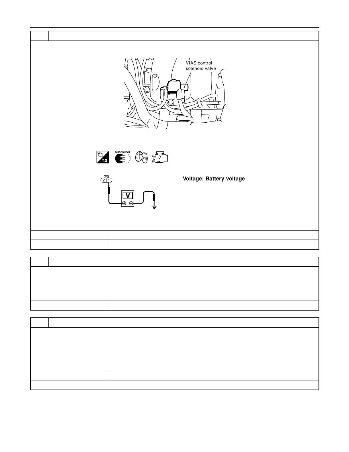
5 CHECK VIAS CONTROL SOLENOID VALVE POWER SUPPLY CIRCUIT
1. Stop engine.
2. Disconnect VIAS control solenoid valve harness connector.
SEC058D
3. Turn ignition switch “ON”.
4. Check voltage between terminal 1 and ground with CONSULT-II or tester.
SEF603X
OK or NG
OK © GO TO 7.
NG © GO TO 6.
6 DETECT MALFUNCTIONING PART
Check the following.
I Harness connectors M161, F68
I Fuse block (J/B) connector M19
I 15A fuse
I Harness continuity between fuse and VIAS control solenoid valve
© Repair harness or connectors.
7 CHECK VIAS CONTROL SOLENOID VALVE OUTPUT SIGNAL CIRCUIT FOR OPEN AND SHORT
1. Turn ignition switch “OFF”.
2. Disconnect ECM harness connector.
3. Check harness continuity between ECM terminal 27 and terminal 2. Refer to Wiring Diagram.
Continuity should exist.
4. Also check harness for short to ground and short to power.
OK or NG
OK © GO TO 8.
NG © Repair open circuit or short to ground or short to power in harness or connectors.
VARIABLE INDUCTION AIR CONTROL SYSTEM (VIAS)
Diagnostic Procedure (Cont’d)
EC-690
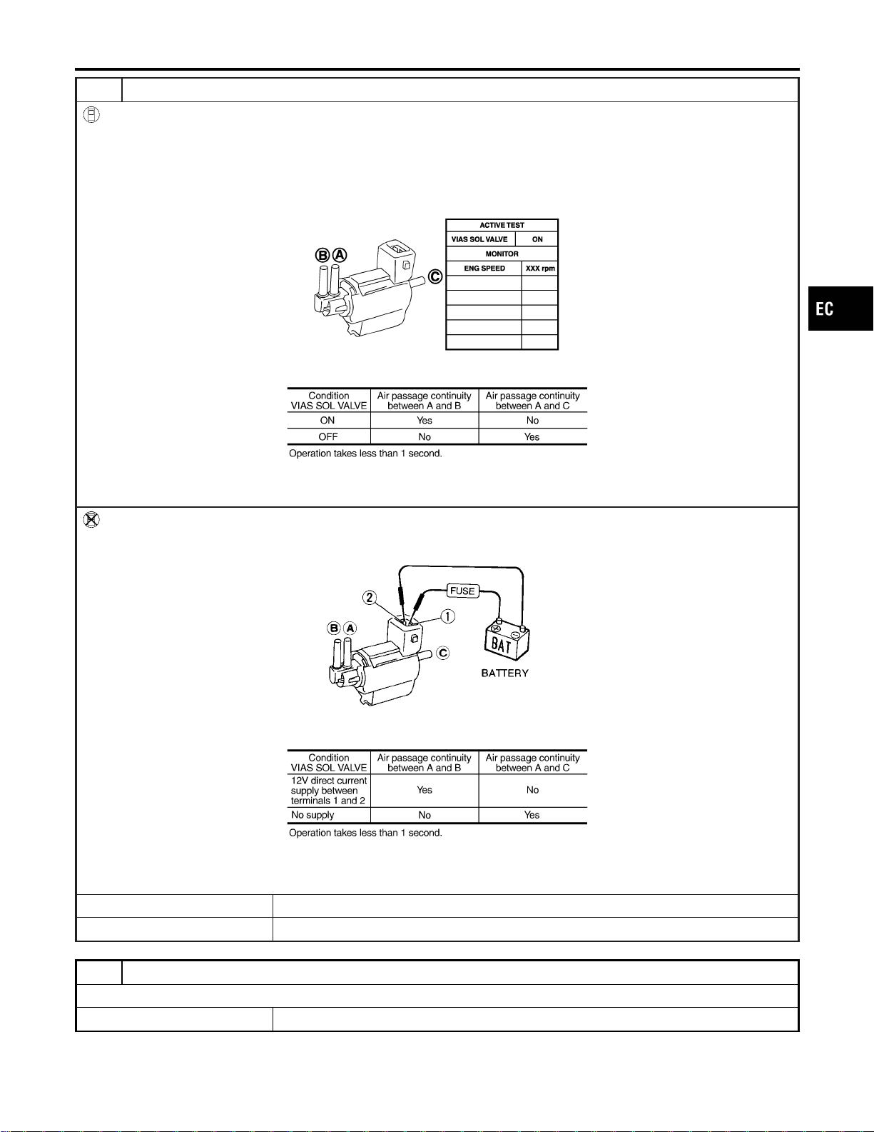
8 CHECK VIAS CONTROL SOLENOID VALVE
With CONSULT-II
1. Reconnect disconnected harness connector.
2. Turn ignition switch ON.
3. Perform “VIAS SOL VALVE” in “ACTIVE TEST” mode.
4. Check air passage continuity and operation delay time under the following conditions.
PBIB0177E
MTBL1301
Without CONSULT-II
Check air passage continuity and operation delay time under the following conditions.
MEC488B
MTBL1302
OK or NG
OK © GO TO 9.
NG © Replace VIAS control solenoid valve.
9 CHECK INTERMITTENT INCIDENT
Refer to “TROUBLE DIAGNOSIS FOR INTERMITTENT INCIDENT”, EC-156.
© INSPECTION END
GI
MA
EM
LC
FE
CL
MT
AT
AX
SU
BR
ST
RS
BT
HA
SC
EL
IDX
VARIABLE INDUCTION AIR CONTROL SYSTEM (VIAS)
Diagnostic Procedure (Cont’d)
EC-691
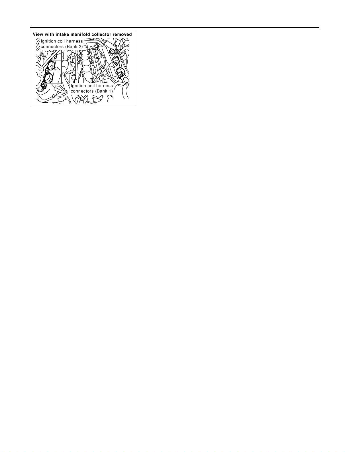
SEC120D
Component Description
NFEC0817
IGNITION COIL & POWER TRANSISTOR
NFEC0817S01
The ignition signal from the ECM is sent to and amplified by the
power transistor. The power transistor turns on and off the ignition
coil primary circuit. This on-off operation induces the proper high
voltage in the coil secondary circuit.
IGNITION SIGNAL
Component Description
EC-692

Wiring Diagram
NFEC0819
MEC501D
GI
MA
EM
LC
FE
CL
MT
AT
AX
SU
BR
ST
RS
BT
HA
SC
EL
IDX
IGNITION SIGNAL
Wiring Diagram
EC-693
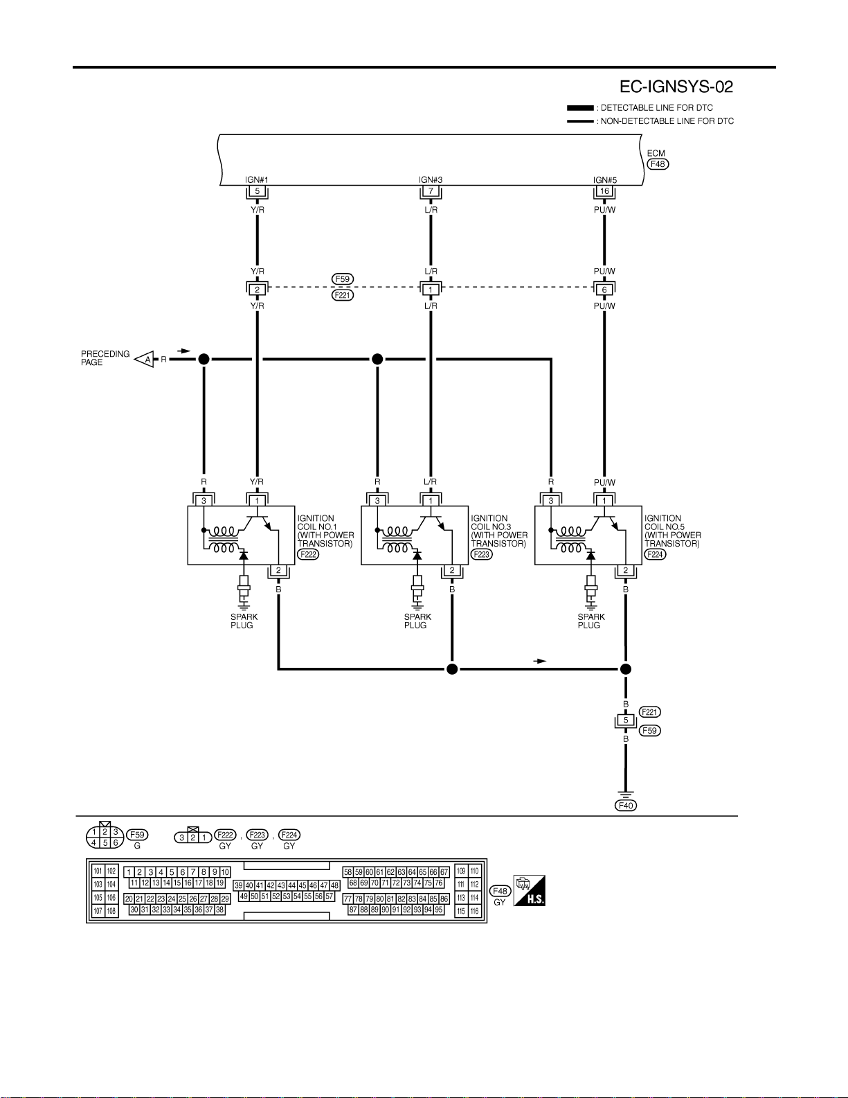
MEC502D
IGNITION SIGNAL
Wiring Diagram (Cont’d)
EC-694
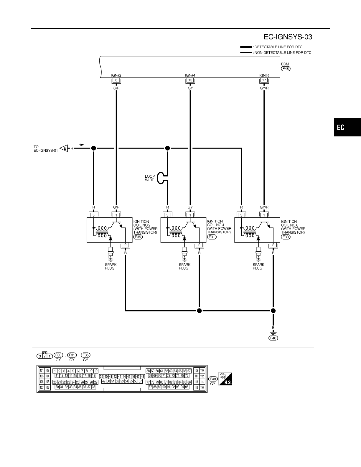
MEC503D
GI
MA
EM
LC
FE
CL
MT
AT
AX
SU
BR
ST
RS
BT
HA
SC
EL
IDX
IGNITION SIGNAL
Wiring Diagram (Cont’d)
EC-695
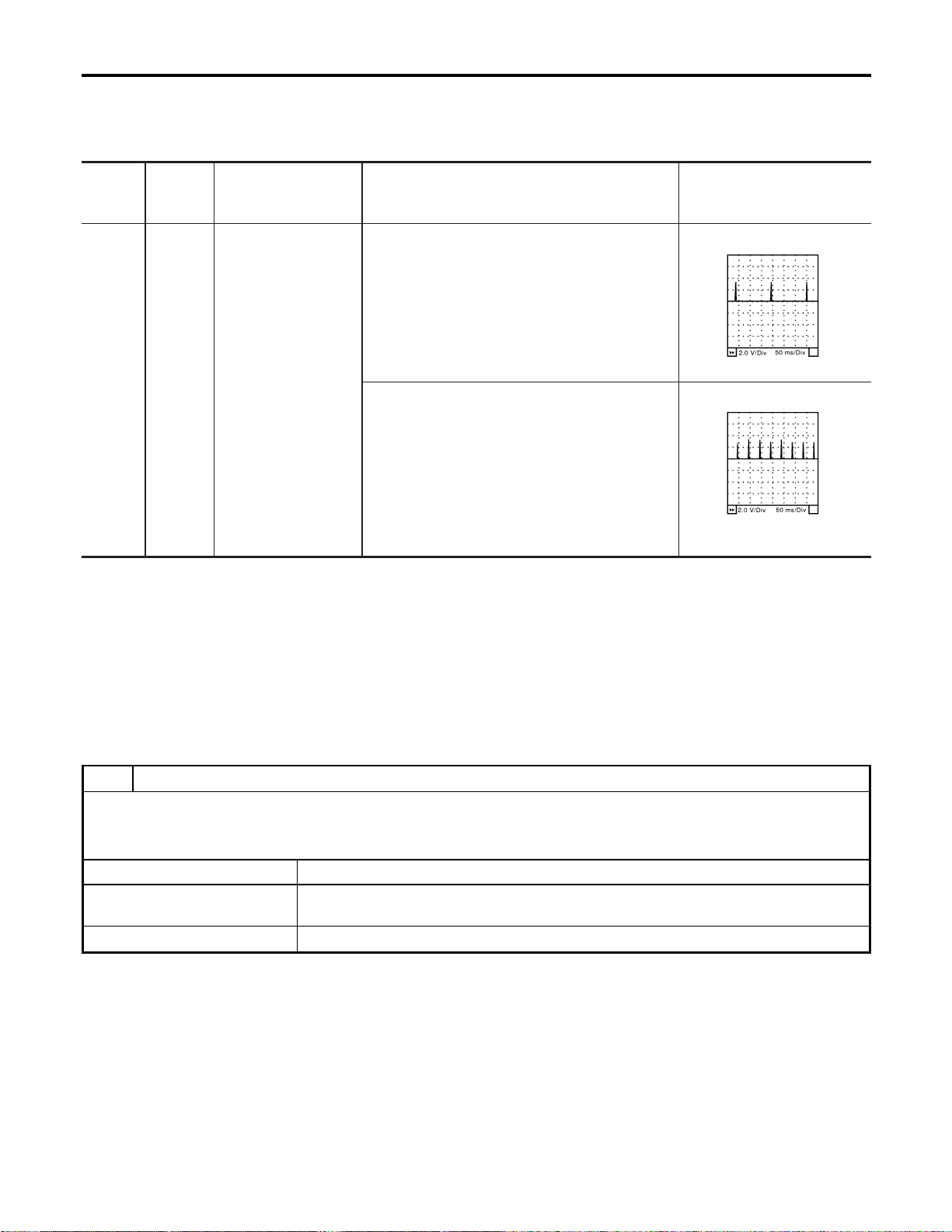
Specification data are reference values and are measured between each terminal and ground.
CAUTION:
Do not use ECM ground terminals when measuring input/output voltage. Doing so may result in dam-
age to the ECM’s transistor. Use a ground other than ECM terminals, such as the ground.
TERMI-
NAL
NO.
WIRE
COLOR
ITEM CONDITION DATA (DC Voltage)
5
6
7
15
16
17
Y/R
G/R
L/R
GY
PU/W
GY/R
Ignition signal No. 1
Ignition signal No. 2
Ignition signal No. 3
Ignition signal No. 4
Ignition signal No. 5
Ignition signal No. 6
[Engine is running]
I Warm-up condition
I Idle speed
0 - 0.2V★
SEC986C
[Engine is running]
I Warm-up condition
I Engine speed is 2,500 rpm.
0.1 - 0.3V★
SEC987C
★: Average voltage for pulse signal (Actual pulse signal can be confirmed by oscilloscope.)
Diagnostic Procedure
NFEC0820
1 CHECK ENGINE START
Turn ignition switch “OFF”, and restart engine.
Is engine running?
YesorNo
Yes (With CONSULT-II) © GO TO 2.
Yes (Without CONSULT-
II)
© GO TO 3.
No © GO TO 4.
IGNITION SIGNAL
Wiring Diagram (Cont’d)
EC-696
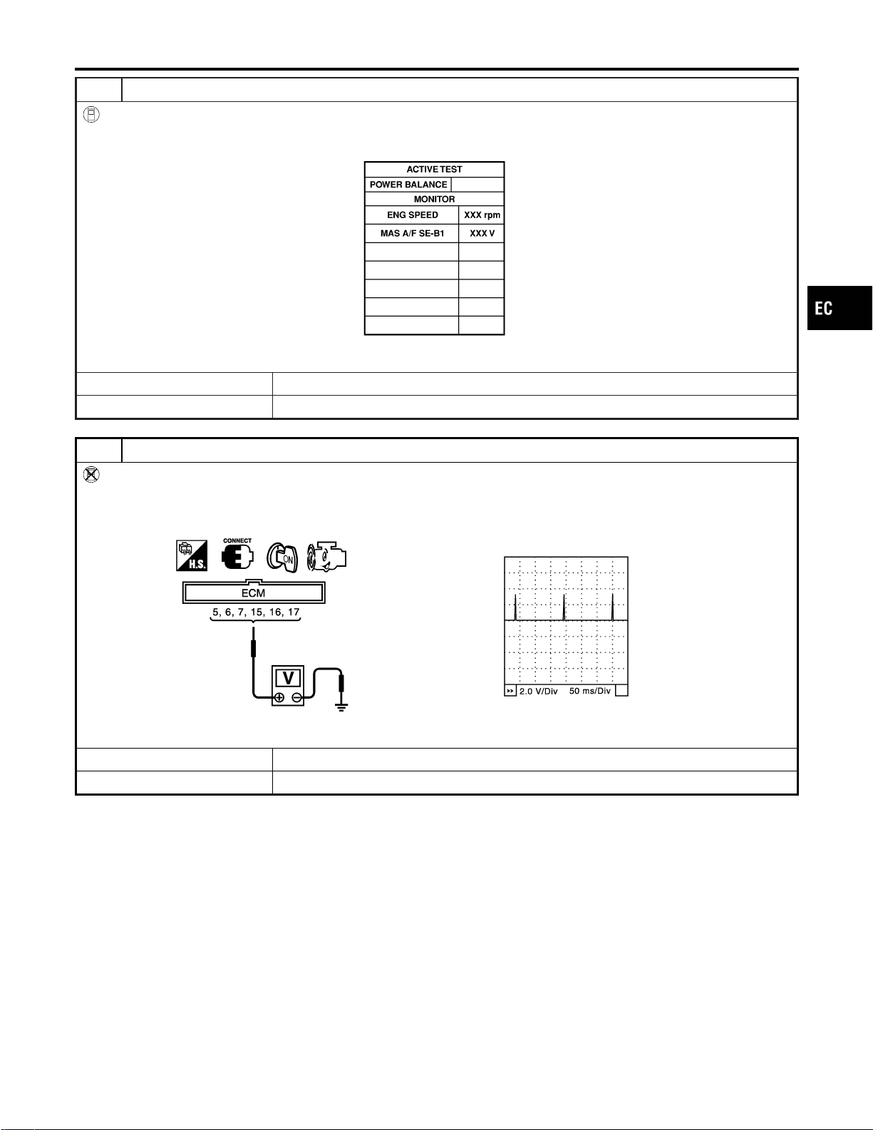
2 CHECK OVERALL FUNCTION
With CONSULT-II
1. Perform “POWER BALANCE” in “ACTIVE TEST” mode with CONSULT-II.
2. Make sure that all circuits do not produce a momentary engine speed drop.
PBIB0133E
OK or NG
OK © INSPECTION END
NG © GO TO 14.
3 CHECK OVERALL FUNCTION
Without CONSULT-II
1. Let engine idle.
2. Read the voltage signal between ECM terminals 5, 6, 7, 15, 16, 17 and ground with oscilloscope.
3. Verify that the oscilloscope screen shows the signal wave as shown below.
SEC159D
OK or NG
OK © INSPECTION END
NG © GO TO 14.
GI
MA
EM
LC
FE
CL
MT
AT
AX
SU
BR
ST
RS
BT
HA
SC
EL
IDX
IGNITION SIGNAL
Diagnostic Procedure (Cont’d)
EC-697
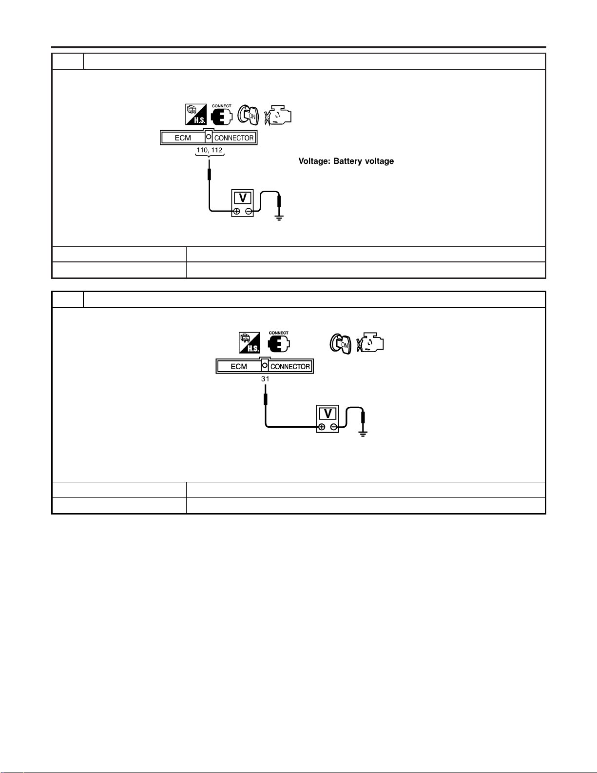
4 CHECK IGNITION COIL POWER SUPPLY CIRCUIT-I
1. Turn ignition switch ON.
2. Check voltage between ECM terminals 110, 112 and ground with CONSULT-II or tester.
SEF366X
OK or NG
OK © GO TO 5.
NG © Go to TROUBLE DIAGNOSIS FOR POWER SUPPLY, EC-157.
5 CHECK IGNITION COIL POWER SUPPLY CIRCUIT-II
1. Check voltage between ECM terminal 31 and ground with CONSULT-II or tester.
SEC914C
Voltage: Battery voltage
OK or NG
OK © GO TO 11.
NG © GO TO 6.
IGNITION SIGNAL
Diagnostic Procedure (Cont’d)
EC-698
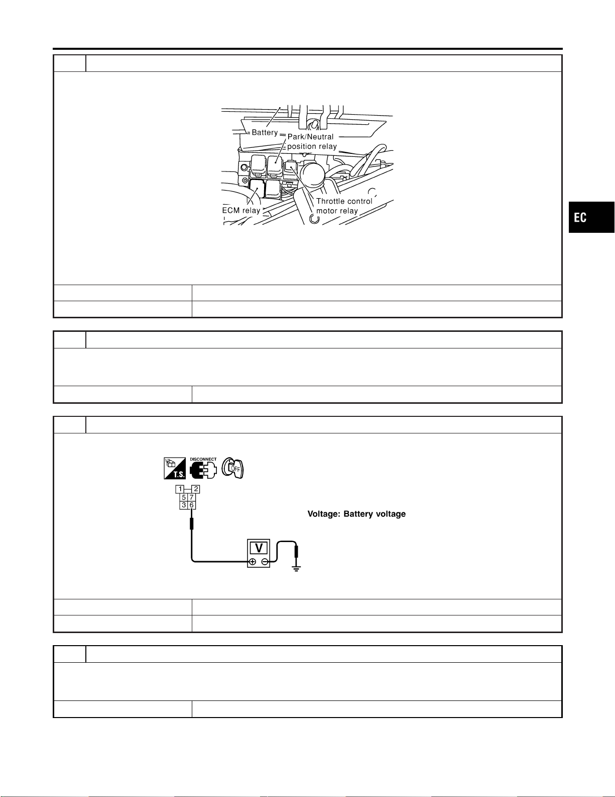
6 CHECK IGNITION COIL POWER SUPPLY CIRCUIT-III
1. Turn ignition switch OFF.
2. Disconnect ECM relay.
SEC044D
3. Check harness continuity between ECM relay terminal 31 and ECM relay terminal 7. Refer to Wiring Diagram.
Continuity should exist.
4. Also check harness for short to ground and short to power.
OK or NG
OK © GO TO 8.
NG © GO TO 7.
7 DETECT MALFUNCTIONING PART
Check the following.
I Harness connectors E15, F18
I Harness for open or short between ECM and ECM relay
© Repair open circuit or short to ground or short to power in harness or connectors.
8 CHECK IGNITION COIL POWER SUPPLY CIRCUIT-IV
Check voltage between ECM relay terminal 6 and ground with CONSULT-II or tester.
SEF368X
OK or NG
OK © GO TO 10.
NG © GO TO 9.
9 DETECT MALFUNCTIONING PART
Check the following.
I 15A fuse
I Harness for open and short between ECM relay and fuse
© Repair or replace harness or connectors.
GI
MA
EM
LC
FE
CL
MT
AT
AX
SU
BR
ST
RS
BT
HA
SC
EL
IDX
IGNITION SIGNAL
Diagnostic Procedure (Cont’d)
EC-699
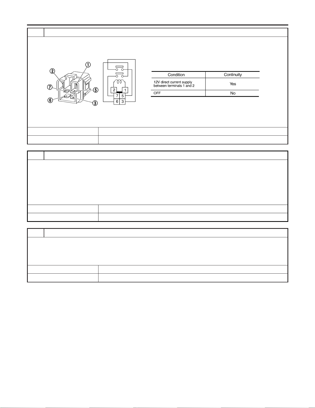
10 CHECK ECM RELAY
1. Apply 12V direct current between ECM relay terminals 1 and 2.
2. Check continuity between ECM relay terminals 3 and 5, 6 and 7.
SEF296X
OK or NG
OK © GO TO 19.
NG © Replace ECM relay.
11 CHECK CONDENSER CIRCUIT FOR OPEN AND SHORT
1. Turn ignition switch “OFF”.
2. Disconnect condenser harness connector.
3. Check harness continuity between ECM terminal 31 and condenser terminal 1.
Refer to Wiring Diagram.
Continuity should exist.
4. Also check for short to ground and short to power.
OK or NG
OK © GO TO 12.
NG © Repair open circuit or short to ground or short to power in harness or connectors.
12 CHECK CONDENSER GROUND CIRCUIT FOR OPEN AND SHORT
1. Check harness continuity between condenser terminal 2 and engine ground. Refer to Wiring Diagram.
Continuity should exist.
2. Also check harness for short to power.
OK or NG
OK © GO TO 13.
NG © Repair open circuit or short to power in harness or connectors.
IGNITION SIGNAL
Diagnostic Procedure (Cont’d)
EC-700
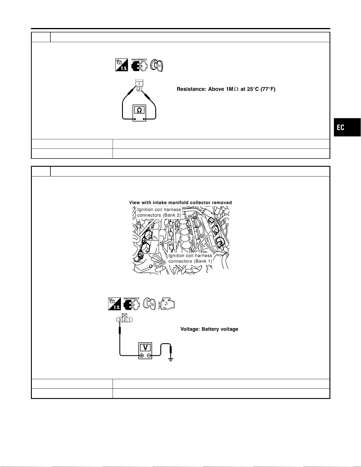
13 CHECK CONDENSER
Check resistance between condenser terminals 1 and 2.
SEF369X
OK or NG
OK © GO TO 14.
NG © Replace condenser.
14 CHECK IGNITION COIL POWER SUPPLY CIRCUIT-V
1. Turn ignition switch OFF.
2. Reconnect harness connectors disconnected.
3. Disconnect ignition coil harness connector.
SEC120D
4. Turn ignition switch ON.
5. Check voltage between ignition coil terminal 3 and ground with CONSULT-II or tester.
SEF370X
OK or NG
OK © GO TO 16.
NG © GO TO 15.
GI
MA
EM
LC
FE
CL
MT
AT
AX
SU
BR
ST
RS
BT
HA
SC
EL
IDX
IGNITION SIGNAL
Diagnostic Procedure (Cont’d)
EC-701
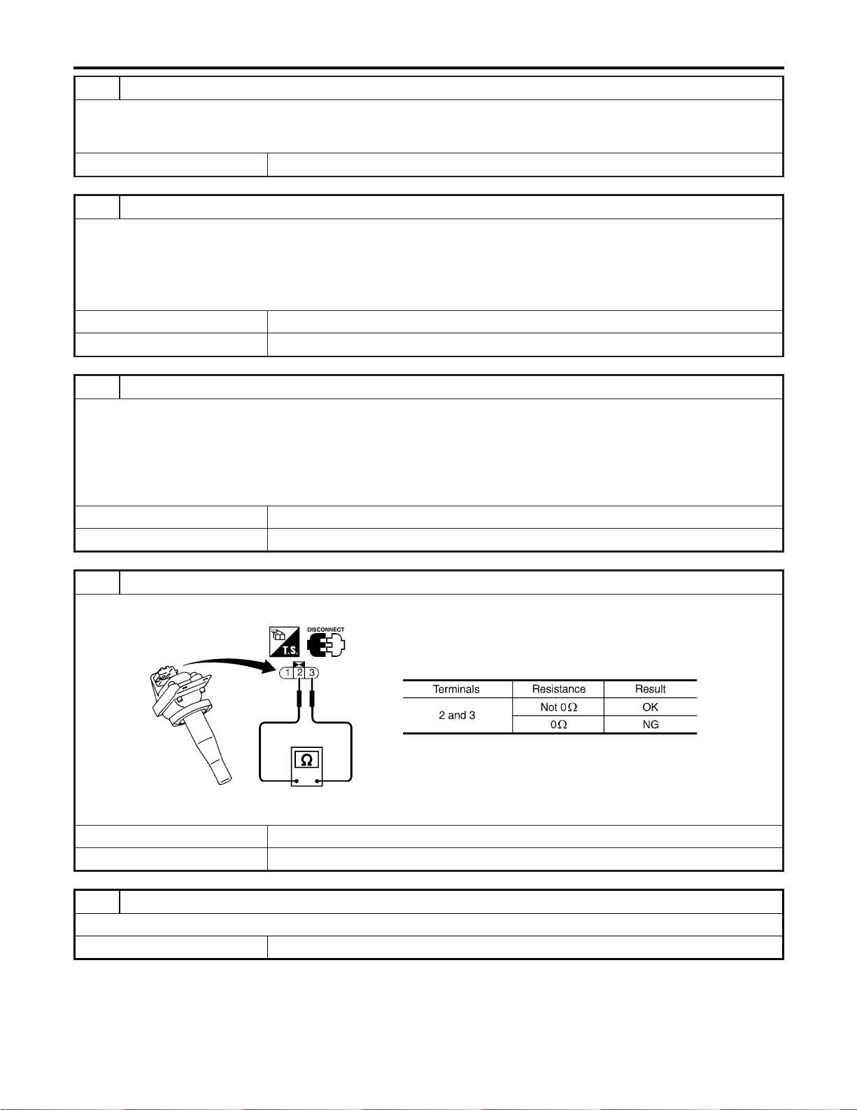
15 DETECT MALFUNCTIONING PART
Check the following.
I Harness connectors F59, F221
I Harness for open and short between ignition coil and harness connector F18
© Repair or replace harness or connectors.
16 CHECK IGNITION COIL GROUND CIRCUIT FOR OPEN AND SHORT
1. Turn ignition switch OFF.
2. Check harness continuity between ignition coil terminal 2 and engine ground. Refer to Wiring Diagram.
Continuity should exist.
3. Also check harness for short to power.
OK or NG
OK © GO TO 17.
NG © Repair open circuit or short to power in harness or connectors.
17 CHECK IGNITION COIL OUTPUT SIGNAL CIRCUIT FOR OPEN AND SHORT
1. Disconnect ECM harness connector.
2. Check harness continuity between ECM terminals 5, 6, 7, 15, 16, 17 and ignition coil terminal 1. Refer to Wiring Dia-
gram.
Continuity should exist.
3. Also check harness for short to ground and short to power.
OK or NG
OK © GO TO 18.
NG © Repair open circuit or short to ground or short to power in harness or connectors.
18 CHECK IGNITION COIL WITH POWER TRANSISTOR
Check resistance between ignition coil terminals 2 and 3.
SEF371X
OK or NG
OK © GO TO 19.
NG © Replace ignition coil with power transistor.
19 CHECK INTERMITTENT INCIDENT
Refer to “TROUBLE DIAGNOSIS FOR INTERMITTENT INCIDENT”, EC-156.
© INSPECTION END
IGNITION SIGNAL
Diagnostic Procedure (Cont’d)
EC-702
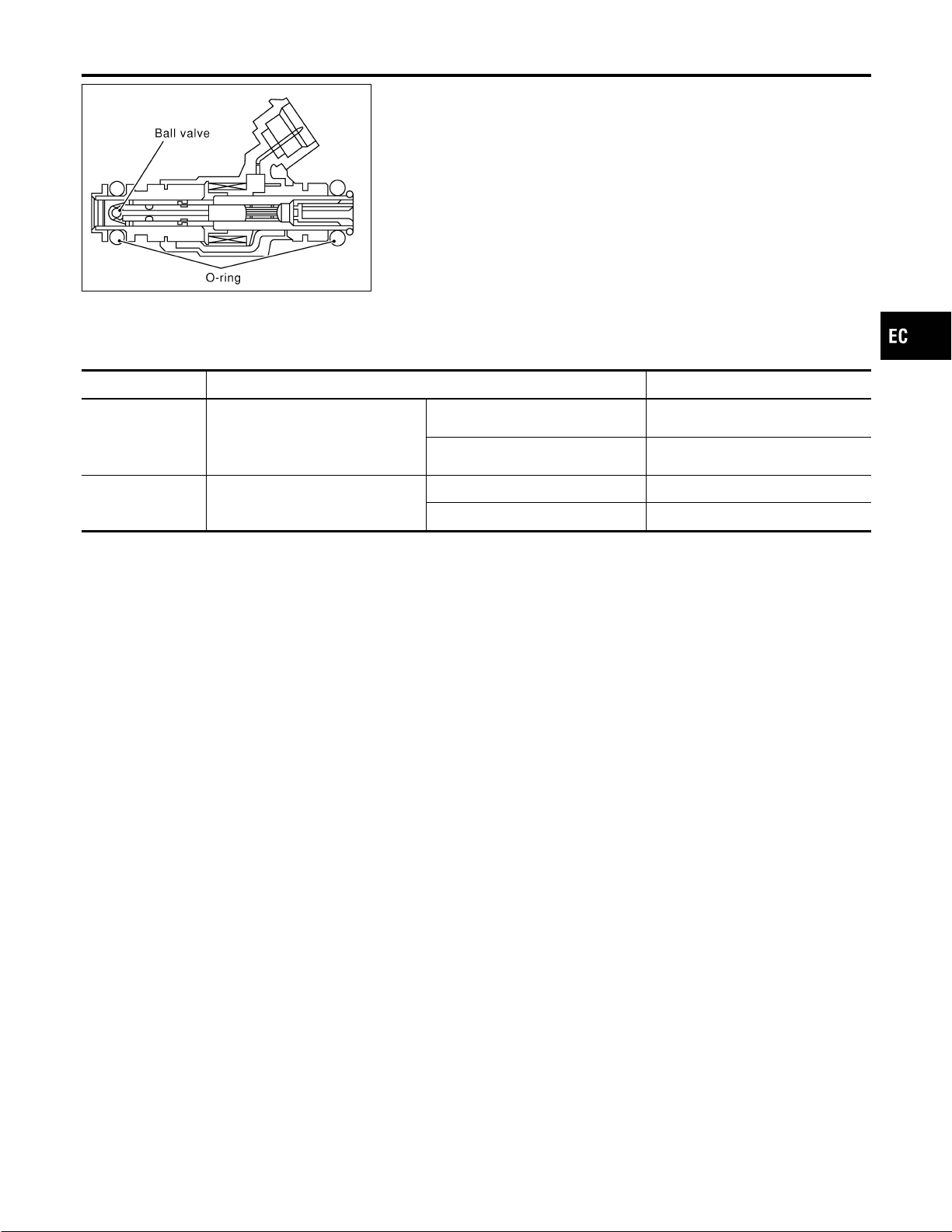
SEF375Z
Component Description
NFEC0383
The fuel injector is a small, precise solenoid valve. When the ECM
supplies a ground to the injector circuit, the coil in the injector is
energized. The energized coil pulls the ball valve back and allows
fuel to flow through the injector into the intake manifold. The
amount of fuel injected depends upon the injection pulse duration.
Pulse duration is the length of time the injector remains open. The
ECM controls the injection pulse duration based on engine fuel
needs.
CONSULT-II Reference Value in Data Monitor
Mode
NFEC0384
Specification data are reference values.
MONITOR ITEM CONDITION SPECIFICATION
INJ PULSE-B2
INJ PULSE-B1
I Engine: After warming up
I Air conditioner switch: “OFF”
I Shift lever: “N”
I No-load
Idle 2.0 - 3.0 msec
2,000 rpm 1.9 - 2.9 msec
B/FUEL SCHDL ditto
Idle 2.3 - 2.9 msec
2,000 rpm 2.3 - 2.9 msec
GI
MA
EM
LC
FE
CL
MT
AT
AX
SU
BR
ST
RS
BT
HA
SC
EL
IDX
INJECTOR
Component Description
EC-703
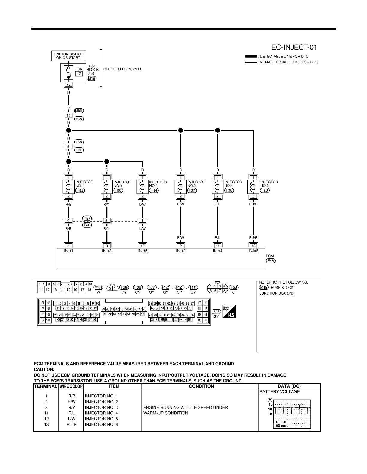
Wiring Diagram
NFEC0386
MEC512D
SEF796YB
INJECTOR
Wiring Diagram
EC-704
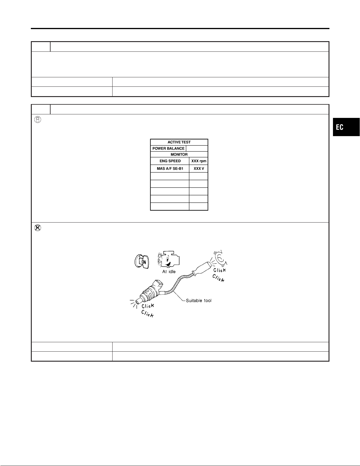
Diagnostic Procedure
NFEC0387
1 INSPECTION START
Turn ignition switch to “START”.
Is any cylinder ignited?
YesorNo
Yes © GO TO 2.
No © GO TO 3.
2 CHECK OVERALL FUNCTION
With CONSULT-II
1. Start engine.
2. Perform “POWER BALANCE” in “ACTIVE TEST” mode with CONSULT-II.
PBIB0133E
3. Make sure that each circuit produces a momentary engine speed drop.
Without CONSULT-II
1. Start engine.
2. Listen to each injector operating sound.
MEC703B
Clicking noise should be heard.
OK or NG
OK © INSPECTION END
NG © GO TO 3.
GI
MA
EM
LC
FE
CL
MT
AT
AX
SU
BR
ST
RS
BT
HA
SC
EL
IDX
INJECTOR
Diagnostic Procedure
EC-705
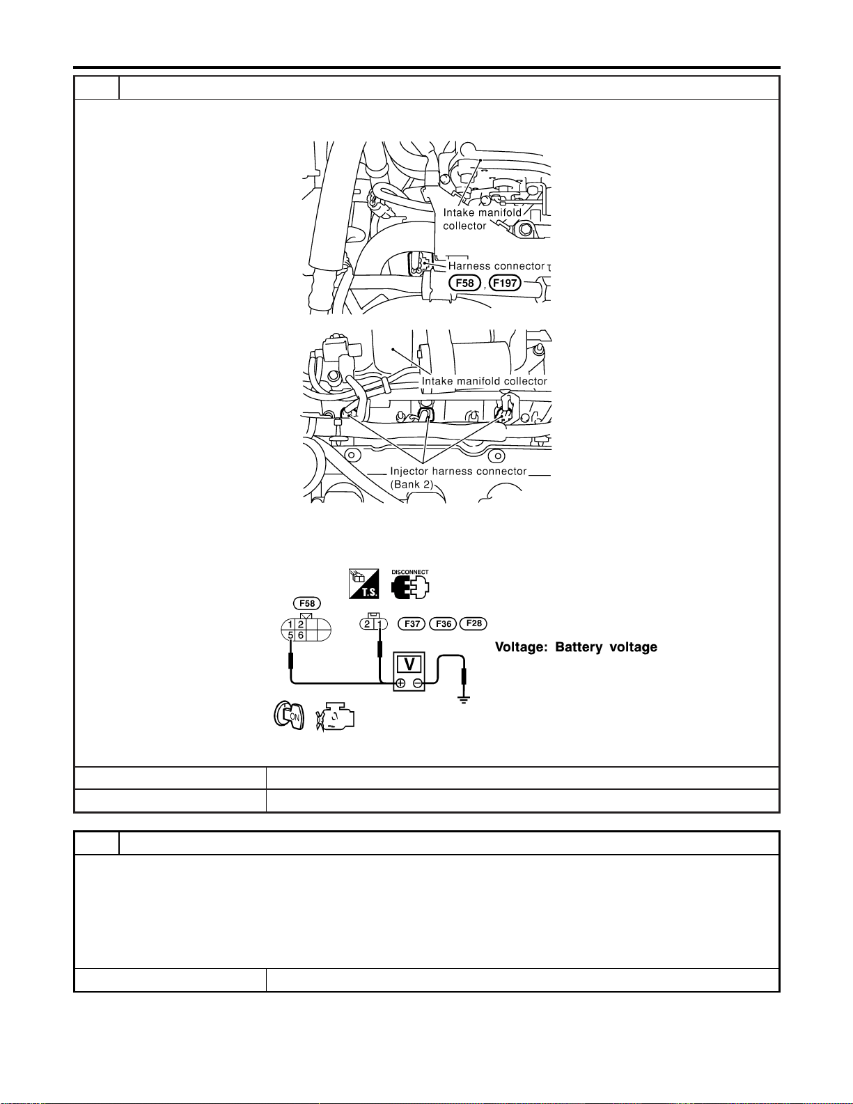
3 CHECK INJECTOR POWER SUPPLY CIRCUIT
1. Turn ignition switch “OFF”.
2. Disconnect injector harness connectors (bank 2) and harness connectors F58, F197 (bank 1).
SEC086D
SEC087D
3. Turn ignition switch “ON”.
4. Check voltage between injector terminal 1 and ground, harness connector F58 terminal 5 and ground with CONSULT-II
or tester.
SEF897XA
OK or NG
OK © GO TO 5.
NG © GO TO 4.
4 DETECT MALFUNCTIONING PART
Check the following.
I Harness connectors M161, F68
I Harness connectors F58, F197
I Fuse block (J/B) connector M19
I 10A fuse
I Harness for open or short between injector and fuse
I Harness for open or short between harness connector F58 and fuse
© Repair harness or connectors.
INJECTOR
Diagnostic Procedure (Cont’d)
EC-706
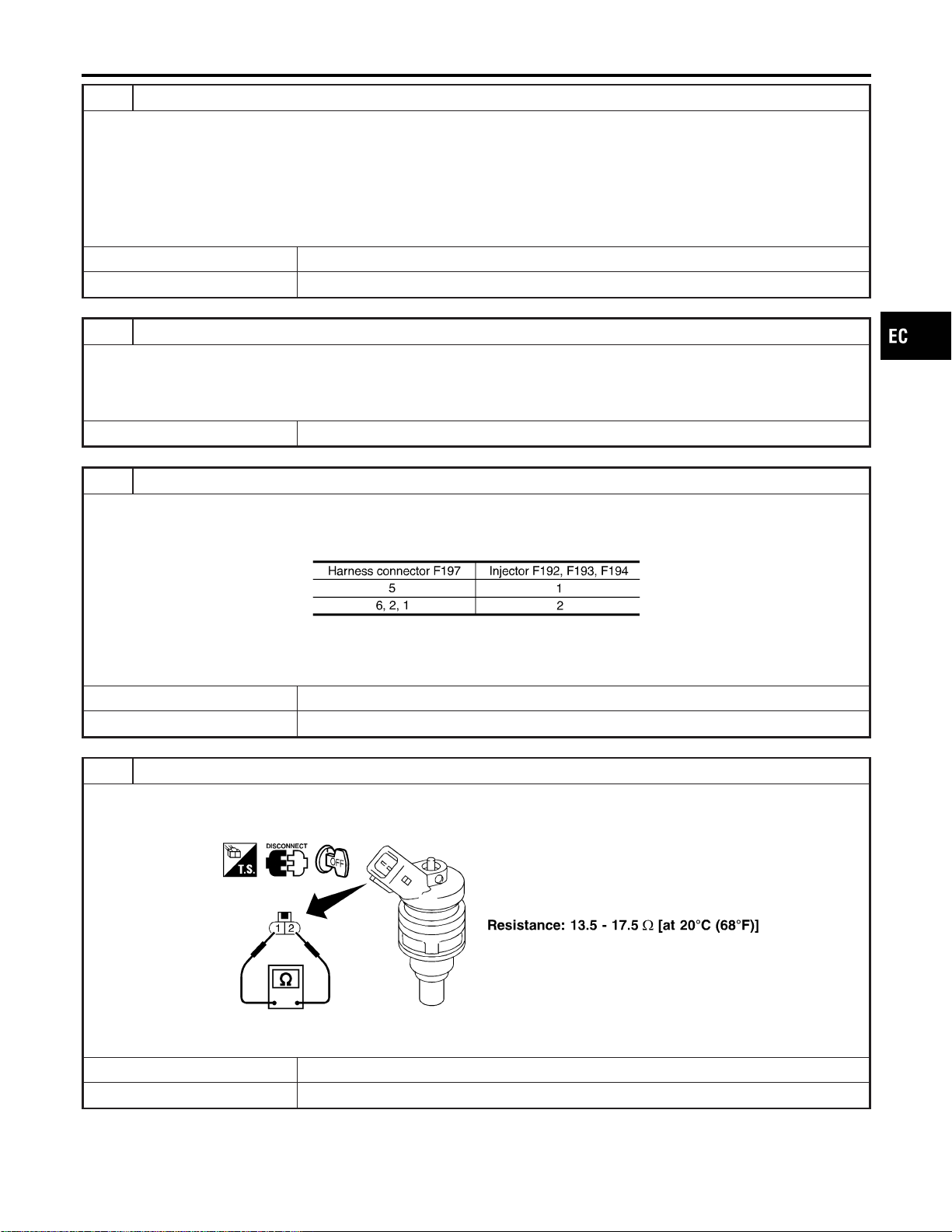
5 CHECK INJECTOR OUTPUT SIGNAL CIRCUIT FOR OPEN AND SHORT
1. Turn ignition switch “OFF”.
2. Disconnect ECM harness connector.
3. Check harness continuity between injector terminal 2 and ECM terminals 2, 11, 13, harness connector F58 terminals 6,
2, 1 and ECM terminals 1, 3, 12. Refer to Wiring Diagram.
Continuity should exist.
4. Also check harness for short to ground and short to power.
OK or NG
OK © GO TO 7.
NG © GO TO 6.
6 DETECT MALFUNCTIONING PART
Check the following.
I Harness connectors F58, F191
I Harness for open or short between harness connector F58 and ECM
I Harness for open or short between ECM and injector
© Repair open circuit or short to ground or short to power in harness or connectors.
7 CHECK SUB-HARNESS CIRCUIT FOR OPEN AND SHORT (BANK 1)
1. Remove intake manifold collector.
2. Disconnect injector harness connectors (Bank 1).
3. Check harness continuity between the following terminals. Refer to Wiring Diagram.
MTBL1173
Continuity should exist.
OK or NG
OK © GO TO 8.
NG © Repair open circuit or short to ground or short to power in harness or connectors.
8 CHECK INJECTOR
1. Disconnect injector harness connector.
2. Check resistance between terminals as shown in the figure.
SEF964XA
OK or NG
OK © GO TO 9.
NG © Replace injector.
GI
MA
EM
LC
FE
CL
MT
AT
AX
SU
BR
ST
RS
BT
HA
SC
EL
IDX
INJECTOR
Diagnostic Procedure (Cont’d)
EC-707

CONSULT-II Reference Value in Data Monitor
Mode
NFEC0388
Specification data are reference values.
MONITOR ITEM CONDITION SPECIFICATION
START SIGNAL I Ignition switch: ON , START , ON OFF , ON , OFF
GI
MA
EM
LC
FE
CL
MT
AT
AX
SU
BR
ST
RS
BT
HA
SC
EL
IDX
START SIGNAL
CONSULT-II Reference Value in Data Monitor Mode
EC-709
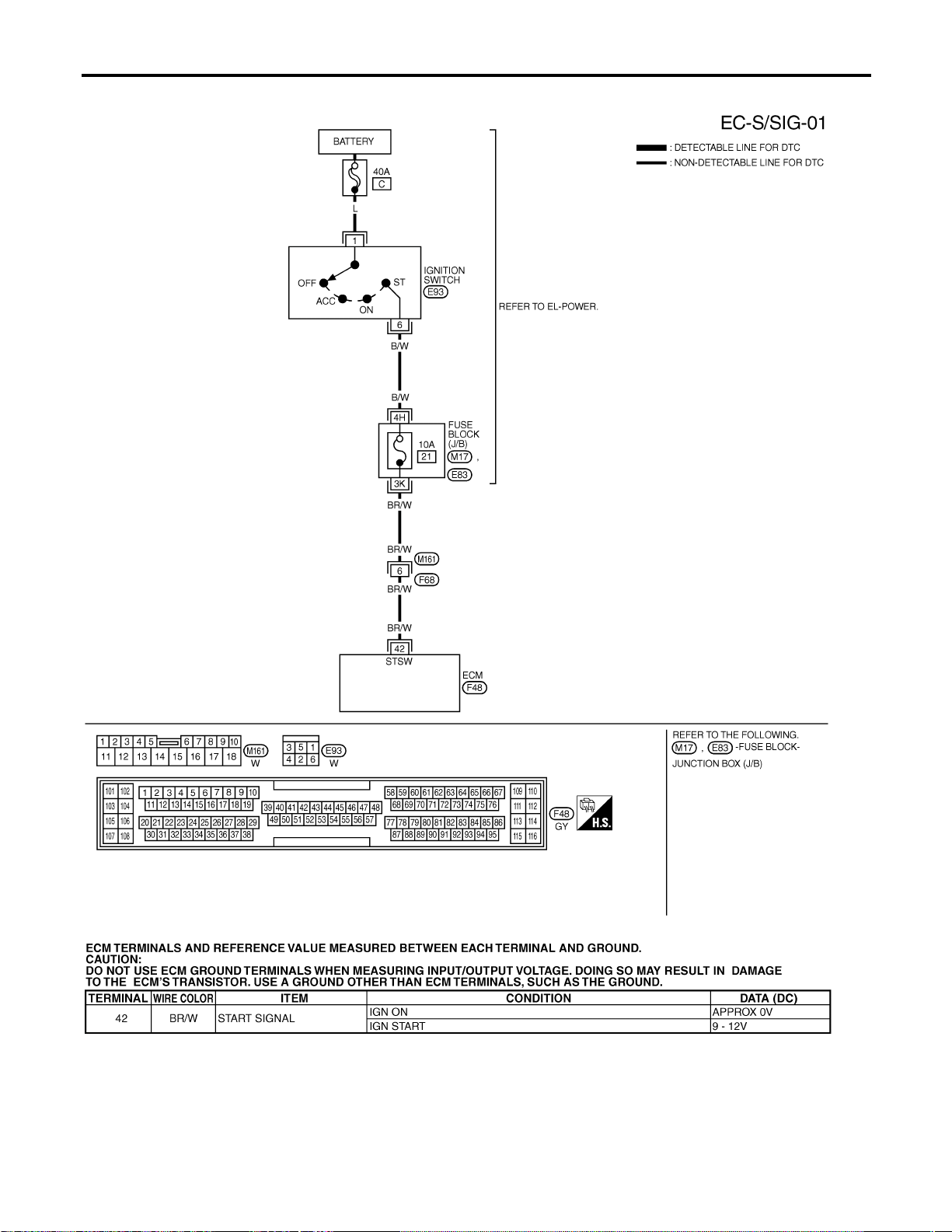
Wiring Diagram
=NFEC0390
MEC513D
SEF638XB
START SIGNAL
Wiring Diagram
EC-710
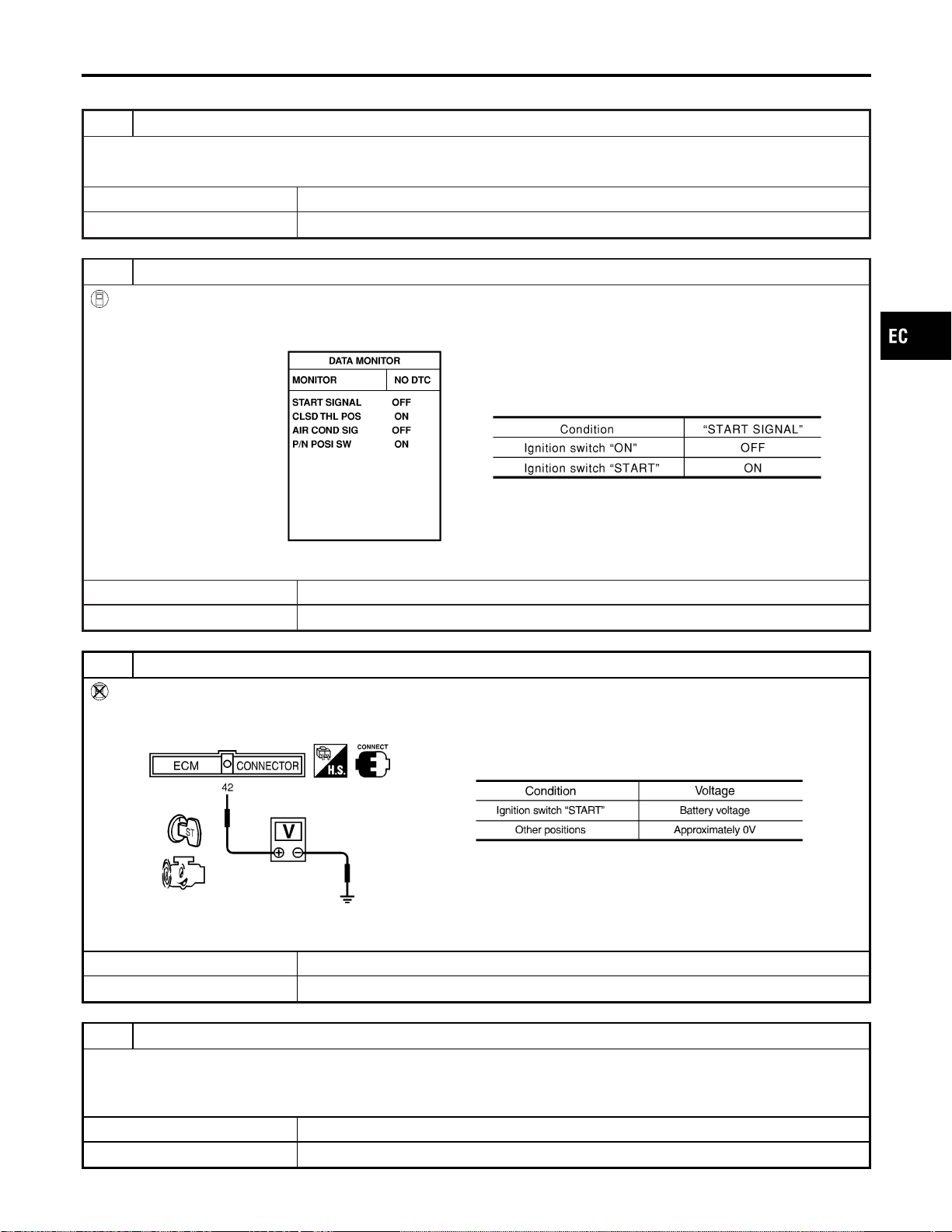
Diagnostic Procedure
NFEC0391
1 INSPECTION START
Do you have CONSULT-II?
YesorNo
Yes © GO TO 2.
No © GO TO 3.
2 CHECK OVERALL FUNCTION
With CONSULT-II
1. Turn ignition switch “ON”.
2. Check “START SIGNAL” in “DATA MONITOR” mode with CONSULT-II under the following conditions.
SEF072Y
OK or NG
OK © INSPECTION END
NG © GO TO 4.
3 CHECK OVERALL FUNCTION
Without CONSULT-II
Check voltage between ECM terminal 42 and ground under the following conditions.
SEF362X
OK or NG
OK © INSPECTION END
NG © GO TO 4.
4 CHECK STARTING SYSTEM
Turn ignition switch “OFF”, then turn it to “START”.
Does starter motor operate?
YesorNo
Yes © GO TO 5.
No © Refer to SC-10, “STARTING SYSTEM”.
GI
MA
EM
LC
FE
CL
MT
AT
AX
SU
BR
ST
RS
BT
HA
SC
EL
IDX
START SIGNAL
Diagnostic Procedure
EC-711
5 CHECK FUSE
1. Turn ignition switch “OFF”.
2. Disconnect 10A fuse.
3. Check if 10A fuse is OK.
OK or NG
OK © GO TO 6.
NG © Replace 10A fuse.
6 CHECK START SIGNAL INPUT SIGNAL CIRCUIT FOR OPEN AND SHORT
1. Disconnect ECM harness connector.
2. Disconnect ignition switch harness connector.
3. Check harness continuity between ECM terminal 42 and ignition switch terminal 6. Refer to Wiring Diagram.
Continuity should exist.
4. Also check harness for short to ground and short to power.
OK or NG
OK © GO TO 8.
NG © GO TO 7.
7 DETECT MALFUNCTIONING PART
Check the following.
I Harness connectors F68, M161
I Fuse block (J/B) connectors M17, E83
I Harness for open or short between ignition switch and ECM
© Repair open circuit or short to ground or short to power in harness or connectors.
8 CHECK INTERMITTENT INCIDENT
Refer to “TROUBLE DIAGNOSIS FOR INTERMITTENT INCIDENT”, EC-156.
© INSPECTION END
START SIGNAL
Diagnostic Procedure (Cont’d)
EC-712
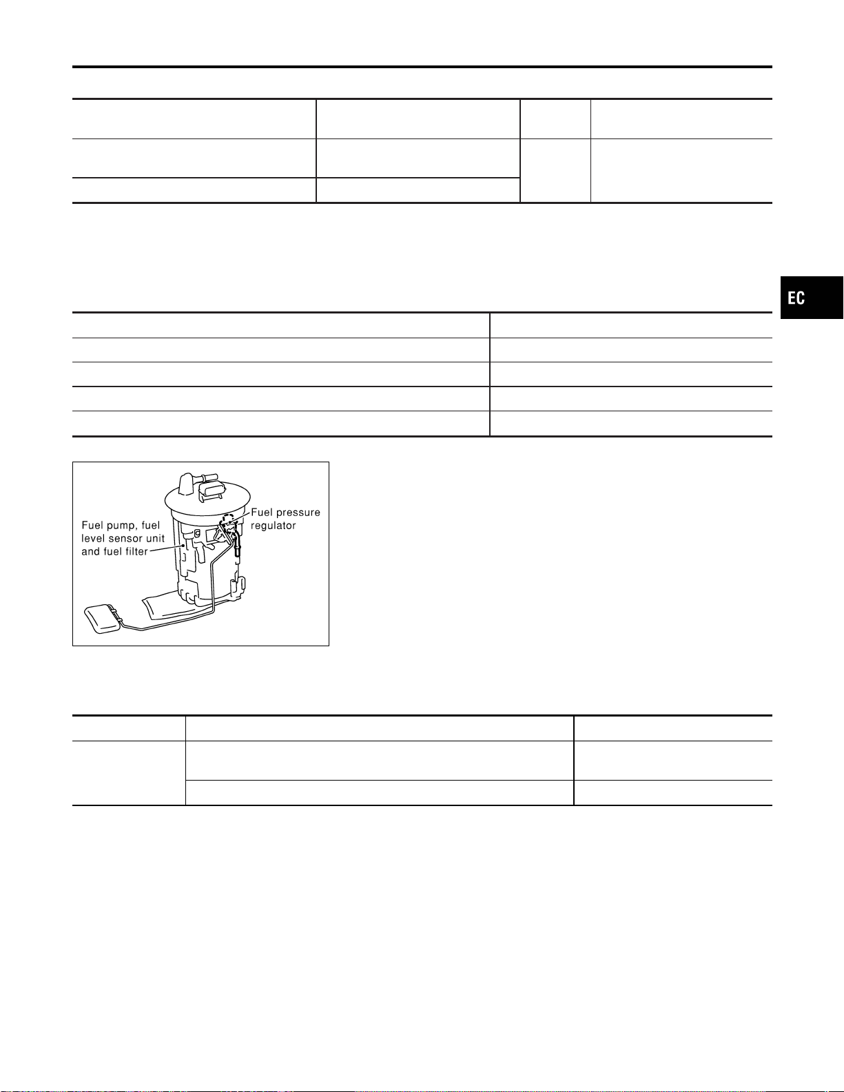
System Description
NFEC0392
Sensor Input Signal to ECM
ECM func-
tion
Actuator
Crankshaft position sensor (POS)
Camshaft position sensor (PHASE)
Engine speed
Fuel pump
control
Fuel pump relay
Ignition switch Start signal
The ECM activates the fuel pump for several seconds after the ignition switch is turned on to improve engine
startability. If the ECM receives a 120° signal from the camshaft position sensor (PHASE), it knows that the
engine is rotating, and causes the pump to operate. If the 120° signal is not received when the ignition switch
is on, the engine stalls. The ECM stops pump operation and prevents battery discharging, thereby improving
safety. The ECM does not directly drive the fuel pump. It controls the ON/OFF fuel pump relay, which in turn
controls the fuel pump.
Condition Fuel pump operation
Ignition switch is turned to ON. Operates for 1 second.
Engine running and cranking Operates.
When engine is stopped Stops in 1.5 seconds.
Except as shown above Stops.
SEC088D
Component Description
NFEC0393
The fuel pump with a fuel damper is an in-tank type (the pump and
damper are located in the fuel tank).
CONSULT-II Reference Value in Data Monitor
Mode
NFEC0394
Specification data are reference values.
MONITOR ITEM CONDITION SPECIFICATION
FUEL PUMP RLY
I Ignition switch is turned to ON. (Operates for 1 second.)
I Engine running and cranking
ON
Except as shown above OFF
GI
MA
EM
LC
FE
CL
MT
AT
AX
SU
BR
ST
RS
BT
HA
SC
EL
IDX
FUEL PUMP
System Description
EC-713
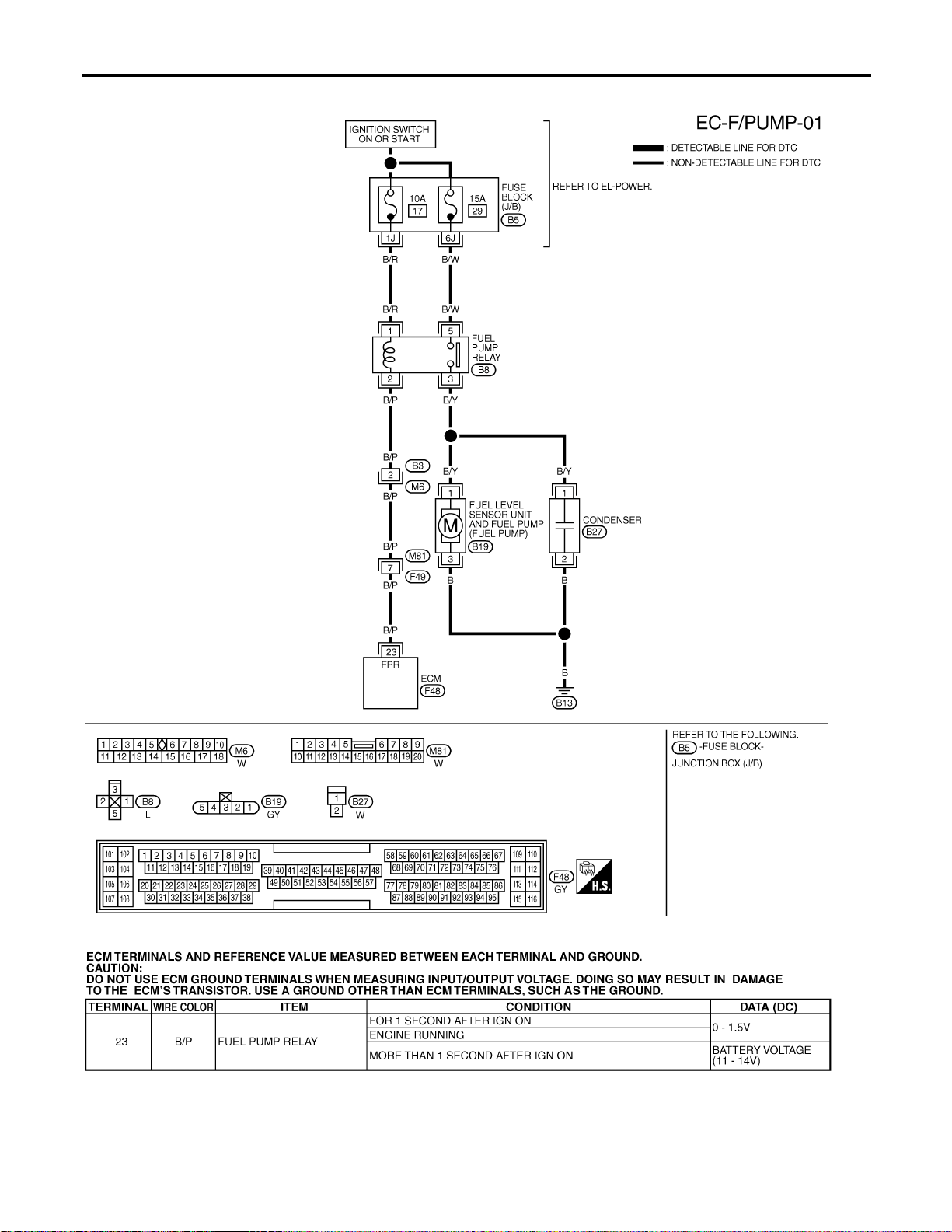
Wiring Diagram
NFEC0396
MEC514D
SEF639XC
FUEL PUMP
Wiring Diagram
EC-714
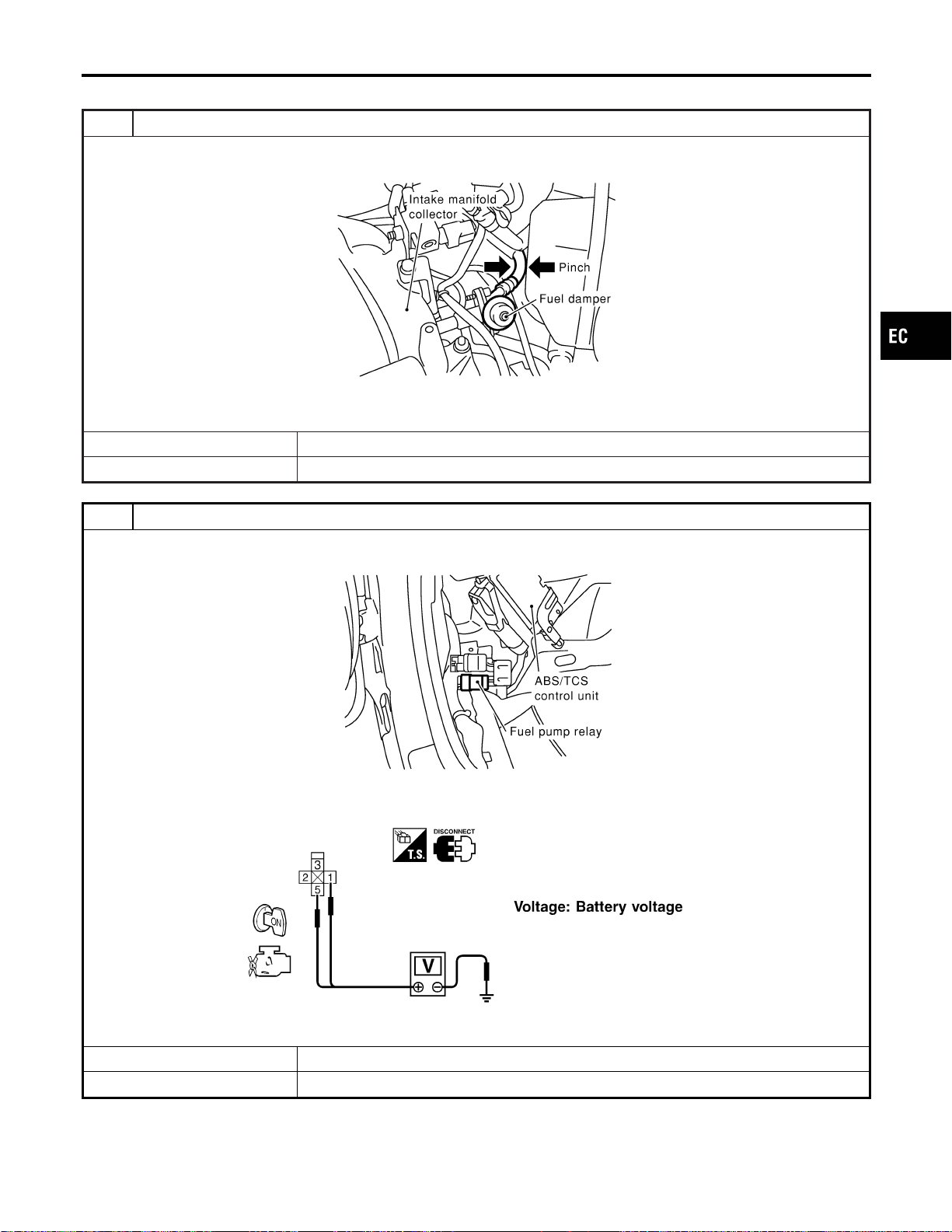
Diagnostic Procedure
NFEC0397
1 CHECK OVERALL FUNCTION
1. Turn ignition switch “ON”.
2. Pinch fuel feed hose with two fingers.
SEC089D
Fuel pressure pulsation should be felt on the fuel feed hose for 1 second after ignition switch is turned “ON”.
OK or NG
OK © INSPECTION END
NG © GO TO 2.
2 CHECK FUEL PUMP RELAY POWER SUPPLY CIRCUIT
1. Turn ignition switch “OFF”.
2. Disconnect fuel pump relay.
SEF284X
3. Turn ignition switch “ON”.
4. Check voltage between terminals 1, 5 and ground with CONSULT-II or tester.
SEF898X
OK or NG
OK © GO TO 4.
NG © GO TO 3.
GI
MA
EM
LC
FE
CL
MT
AT
AX
SU
BR
ST
RS
BT
HA
SC
EL
IDX
FUEL PUMP
Diagnostic Procedure
EC-715
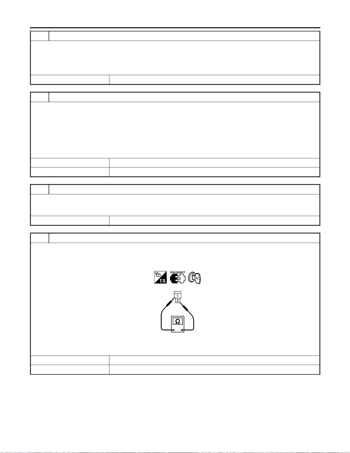
3 DETECT MALFUNCTIONING PART
Check the following.
I Fuse block (J/B) connector B5
I 10A fuse
I 15A fuse
I Harness for open or short between fuse and fuel pump relay
© Repair harness or connectors.
4 CHECK CONDENSER CIRCUIT FOR OPEN AND SHORT
1. Turn ignition switch “OFF”.
2. Disconnect condenser harness connector.
3. Check harness continuity between fuel pump relay terminal 3 and condenser terminal 1, condenser terminal 2 and
body ground.
Refer to Wiring Diagram.
Continuity should exist.
4. Also check harness for short to ground and short to power.
OK or NG
OK © GO TO 6.
NG © GO TO 5.
5 DETECT MALFUNCTIONING PART
Check the following.
I Harness for open or short between fuel pump relay and condenser
I Harness for open or short between condenser and body ground
© Repair open circuit or short to ground or short to power in harness or connectors.
6 CHECK CONDENSER
1. Turn ignition switch “OFF”.
2. Disconnect condenser harness connector.
3. Check resistance between condenser terminals 1 and 2.
SEF124Y
Resistance: Above 1 MΩ at 25°C (77°F)
OK or NG
OK © GO TO 7.
NG © Replace condenser.
FUEL PUMP
Diagnostic Procedure (Cont’d)
EC-716
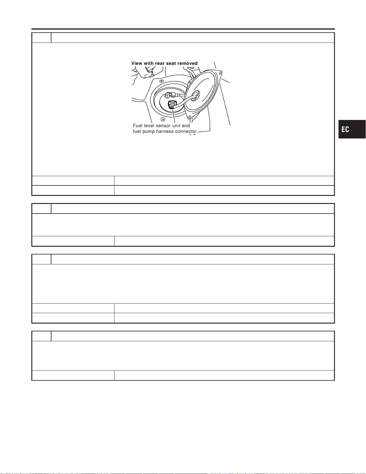
7 CHECK FUEL PUMP POWER SUPPLY AND GROUND CIRCUIT FOR OPEN AND SHORT
1. Turn ignition switch “OFF”.
2. Disconnect fuel level sensor unit and fuel pump harness connector.
SEC082D
3. Check harness continuity between fuel pump terminal 3 and body ground, fuel pump terminal 1 and fuel pump relay
terminal 3. Refer to Wiring Diagram.
Continuity should exist.
4. Also check harness for short to ground and short to power.
OK or NG
OK © GO TO 9.
NG © GO TO 8.
8 DETECT MALFUNCTIONING PART
Check the following.
I Harness for open or short between fuel pump relay and fuel pump
I Harness for open or short between fuel pump and body ground
© Repair open circuit or short to ground or short to power in harness or connectors.
9 CHECK FUEL PUMP RELAY OUTPUT SIGNAL CIRCUIT FOR OPEN AND SHORT
1. Disconnect ECM harness connector.
2. Check harness continuity between ECM terminal 23 and fuel pump relay terminal 2. Refer to Wiring Diagram.
Continuity should exist.
3. Also check harness for short to ground and short to power.
OK or NG
OK © GO TO 11.
NG © GO TO 10.
10 DETECT MALFUNCTIONING PART
Check the following.
I Harness connectors B3, M6
I Harness connectors M81, F49
I Harness for open or short between ECM and fuel pump relay
© Repair open circuit or short to ground or short to power in harness or connectors.
GI
MA
EM
LC
FE
CL
MT
AT
AX
SU
BR
ST
RS
BT
HA
SC
EL
IDX
FUEL PUMP
Diagnostic Procedure (Cont’d)
EC-717

11 CHECK FUEL PUMP RELAY
With CONSULT-II
1. Reconnect fuel pump relay, fuel level sensor unit and fuel pump harness connector and ECM harness connector.
2. Turn ignition switch “ON”.
3. Turn fuel pump relay “ON” and “OFF” in “ACTIVE TEST” mode with CONSULT-II and check operating sound.
SEF073Y
Without CONSULT-II
Check continuity between terminals 3 and 5 under the following conditions.
SEF608X
OK or NG
OK © GO TO 12.
NG © Replace fuel pump relay.
12 CHECK FUEL PUMP
1. Disconnect fuel level sensor unit and fuel pump harness connector.
2. Check resistance between fuel level sensor unit and fuel pump terminals 1 and 3.
SEC918C
Resistance: 0.2 - 5.0Ω [at 25°C (77°F)]
OK or NG
OK © GO TO 13.
NG © Replace fuel pump.
FUEL PUMP
Diagnostic Procedure (Cont’d)
EC-718

System Description
NFEC1328
Sensor Input Signal to ECM
ECM func-
tion
Actuator
Crankshaft position sensor (POS)
Camshaft position sensor (PHASE)
Engine speed
Engine
mount con-
trol
Electronic controlled engine
mount
Wheel sensor Vehicle speed
The ECM controls the engine mount operation corresponding to
the engine speed and the vehicle speed. The control system has
2-step control [soft/hard].
Vehicle condition Engine mount control
Idle (with vehicle stopped) Soft
Driving Hard
CONSULT-II Reference Value in Data Monitor
Mode
NFEC1329
Specification data are reference values.
MONITOR ITEM CONDITION SPECIFICATION
ENGINE MOUNT I Engine: Running
Idle “IDLE”
Except above “TRVL”
ELECTRONIC CONTROLLED ENGINE MOUNT
System Description
EC-720
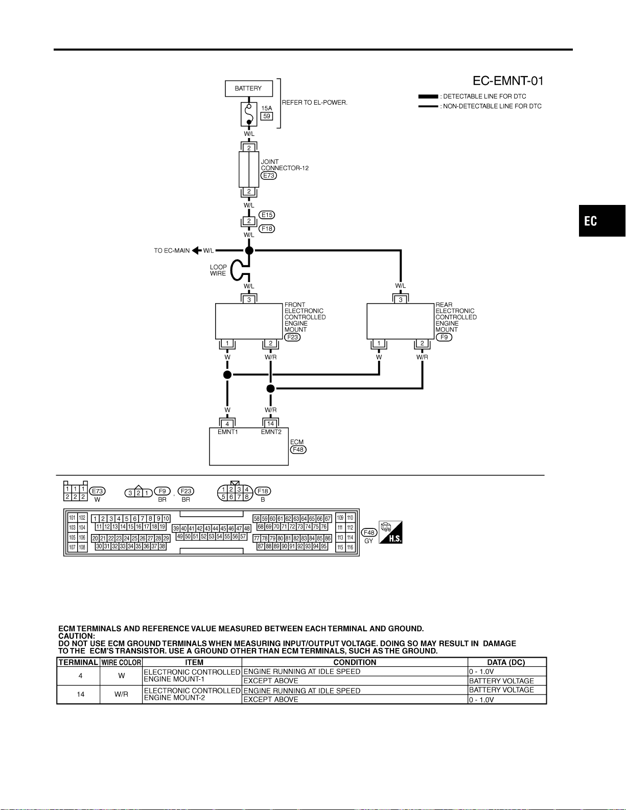
Wiring Diagram
NFEC1330
MEC515D
SEF640XC
GI
MA
EM
LC
FE
CL
MT
AT
AX
SU
BR
ST
RS
BT
HA
SC
EL
IDX
ELECTRONIC CONTROLLED ENGINE MOUNT
Wiring Diagram
EC-721
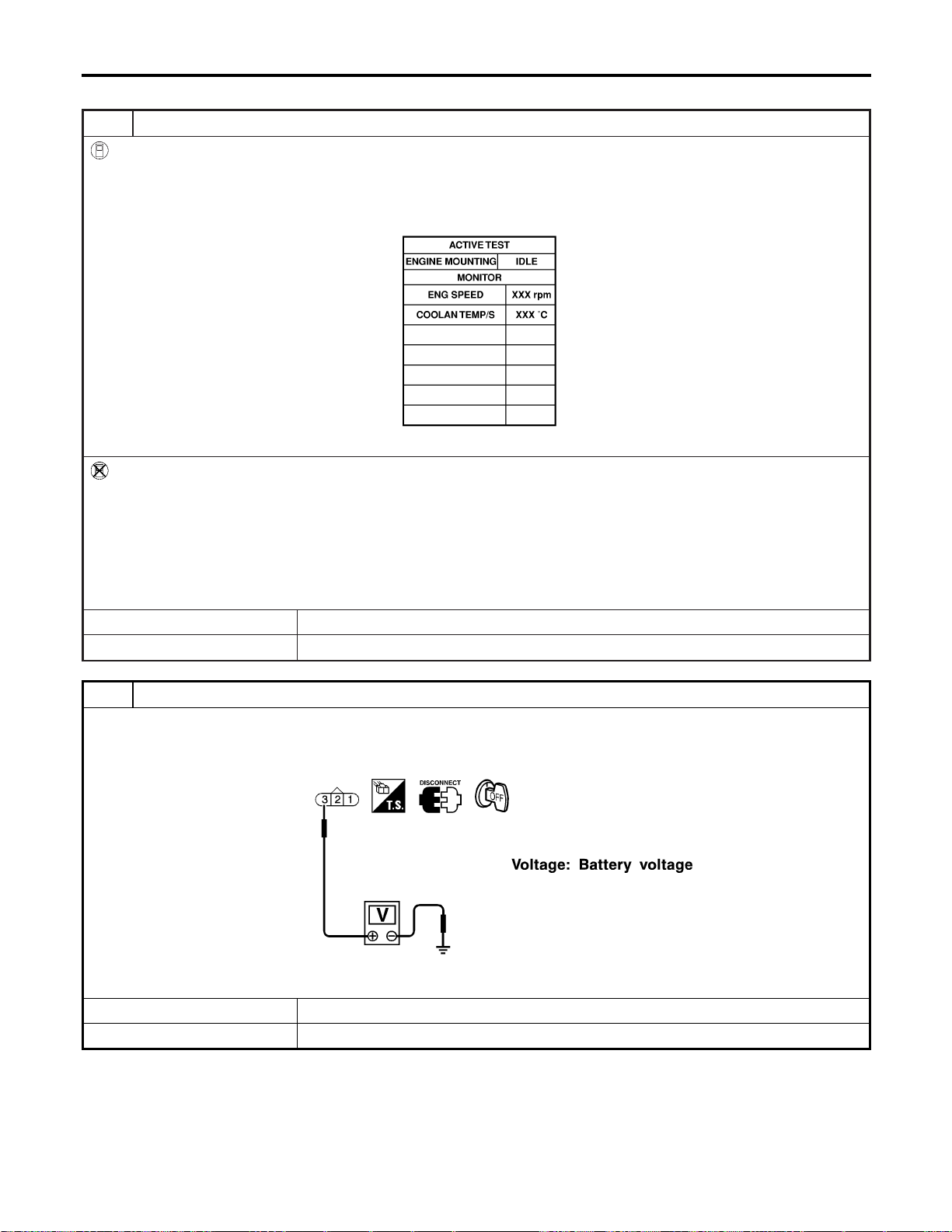
Diagnostic Procedure
NFEC1331
1 CHECK THE OVERALL FUNCTION
With CONSULT-II
1. After warming up engine, run it at idle speed.
2. Shift selector lever to “D” range while depressing the brake pedal and pulling the parking brake control lever.
3. Perform “ENGINE MOUNTING” in “ACTIVE TEST” mode with CONSULT-II and check that the body vibration changes
according to switching the condition (With vehicle stopped).
SEC237C
Without CONSULT-II
1. After warming up engine, run it at idle speed.
2. Shift selector lever to “D” range while depressing the brake pedal and pulling the parking brake control lever.
3. Disconnect front or rear electronic controlled engine mount harness connector when engine speed is more than 1,000
rpm.
4. When returning engine speed to idle speed, check that the body vibration increases, compared with the condition of the
above step 2 (With vehicle stopped).
OK or NG
OK © INSPECTION END
NG © GO TO 2.
2 CHECK ELECTRONIC CONTROLLED ENGINE MOUNT POWER SUPPLY CIRCUIT
1. Turn ignition switch “OFF”.
2. Disconnect front or rear electronic controlled engine mount harness connector.
3. Check voltage between electronic controlled engine mount terminal 3 and ground with CONSULT-II or tester.
SEF899X
OK or NG
OK © GO TO 4.
NG © GO TO 3.
ELECTRONIC CONTROLLED ENGINE MOUNT
Diagnostic Procedure
EC-722
3 DETECT MALFUNCTIONING PART
Check the following.
I Harness connectors E15, F18
I 15A fuse
I Joint connector-12
I Harness for open or short between electronic controlled engine mount and battery
© Repair harness or connectors.
4 CHECK ELECTRONIC CONTROLLED ENGINE MOUNT OUTPUT SIGNAL CIRCUIT FOR OPEN AND
SHORT
1. Disconnect ECM harness connector.
2. Check harness continuity between ECM terminal 4 and electronic controlled engine mount terminal 1, ECM terminal 14
and electronic controlled engine mount terminal 2. Refer to Wiring Diagram.
Continuity should exist.
3. Also check harness for short to ground and short to power.
OK or NG
OK © GO TO 5.
NG © Repair open circuit, short to ground or short to power in harness connectors.
5 CHECK ELECTRONIC CONTROLLED ENGINE MOUNT
Visually check front and rear electronic controlled engine mount.
OK or NG
OK © GO TO 6.
NG © Replace front or rear engine mount assembly.
6 CHECK INTERMITTENT INCIDENT
Refer to “TROUBLE DIAGNOSIS FOR INTERMITTENT INCIDENT”, EC-156.
© INSPECTION END
GI
MA
EM
LC
FE
CL
MT
AT
AX
SU
BR
ST
RS
BT
HA
SC
EL
IDX
ELECTRONIC CONTROLLED ENGINE MOUNT
Diagnostic Procedure (Cont’d)
EC-723
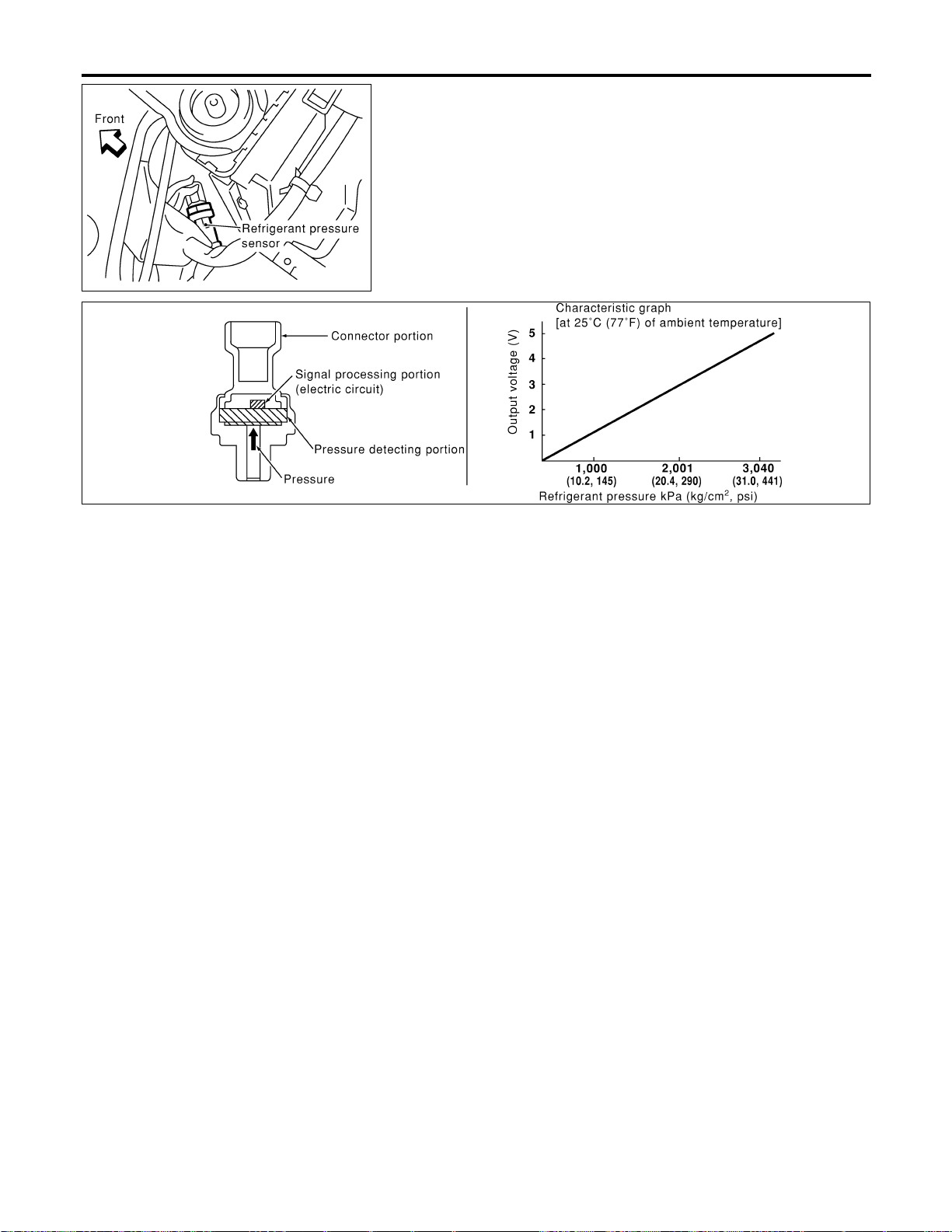
SEC084D
Description
NFEC0636
The refrigerant pressure sensor is installed at the liquid tank of the
air conditioner system. The sensor uses an electrostatic volume
pressure transducer to convert refrigerant pressure to voltage. The
voltage signal is sent to ECM, and ECM controls cooling fan sys-
tem.
SEF099XA
REFRIGERANT PRESSURE SENSOR
Description
EC-724
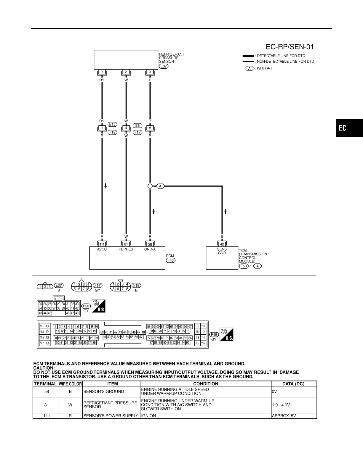
Wiring Diagram
NFEC0637
MEC517D
SEF643XC
GI
MA
EM
LC
FE
CL
MT
AT
AX
SU
BR
ST
RS
BT
HA
SC
EL
IDX
REFRIGERANT PRESSURE SENSOR
Wiring Diagram
EC-725
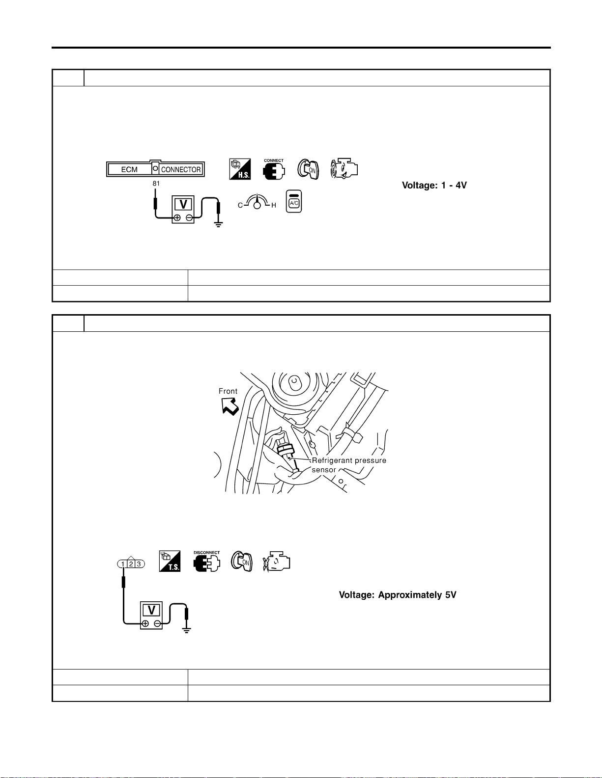
Diagnostic Procedure
NFEC0638
1 CHECK REFRIGERANT PRESSURE SENSOR OVERALL FUNCTION
1. Start engine and warm it up to normal operating temperature.
2. Turn A/C switch and blower switch “ON”.
3. Check voltage between ECM terminal 81 and ground with CONSULT-II or tester.
SEF617XA
OK or NG
OK © INSPECTION END
NG © GO TO 2.
2 CHECK REFRIGERANT PRESSURE SENSOR POWER SUPPLY CIRCUIT
1. Turn A/C switch and blower switch “OFF”.
2. Stop engine.
3. Disconnect refrigerant pressure sensor harness connector.
SEC084D
4. Turn ignition switch “ON”.
5. Check voltage between refrigerant pressure sensor terminal 1 and ground with CONSULT-II or tester.
SEF618X
OK or NG
OK © GO TO 4.
NG © GO TO 3.
REFRIGERANT PRESSURE SENSOR
Diagnostic Procedure
EC-726
3 DETECT MALFUNCTIONING PART
Check the following.
I Harness connectors E15, F18
I Harness for open or short between ECM and refrigerant pressure sensor
© Repair harness or connectors.
4 CHECK REFRIGERANT PRESSURE SENSOR GROUND CIRCUIT FOR OPEN AND SHORT
1. Turn ignition switch “OFF”.
2. Check harness continuity between refrigerant pressure sensor terminal 3 and engine ground. Refer to Wiring Diagram.
Continuity should exist.
3. Also check harness for short to power.
OK or NG
OK © GO TO 6.
NG © GO TO 5.
5 DETECT MALFUNCTIONING PART
Check the following.
I Harness connectors E8, F17
I Harness for open between ECM and refrigerant pressure sensor
I Harness for open between TCM (Transmission control module) and refrigerant pressure sensor
© Repair open circuit or short to power in harness or connectors.
6 CHECK REFRIGERANT PRESSURE SENSOR INPUT SIGNAL CIRCUIT FOR OPEN AND SHORT
1. Disconnect ECM harness connector.
2. Check harness continuity between ECM terminal 81 and refrigerant pressure sensor terminal 2. Refer to Wiring Dia-
gram.
Continuity should exist.
3. Also check harness for short to ground and short to power.
OK or NG
OK © GO TO 8.
NG © GO TO 7.
7 DETECT MALFUNCTIONING PART
Check the following.
I Harness connectors E8, F17
I Harness for open or short between ECM and refrigerant pressure sensor
© Repair open circuit or short to ground or short to power in harness or connectors.
8 CHECK REFRIGERANT PRESSURE SENSOR
Refer to HA-15, “Refrigerant pressure sensor”.
OK or NG
OK © GO TO 9.
NG © Replace refrigerant pressure sensor.
9 CHECK INTERMITTENT INCIDENT
Refer to “TROUBLE DIAGNOSIS FOR INTERMITTENT INCIDENT”, EC-156.
© INSPECTION END
GI
MA
EM
LC
FE
CL
MT
AT
AX
SU
BR
ST
RS
BT
HA
SC
EL
IDX
REFRIGERANT PRESSURE SENSOR
Diagnostic Procedure (Cont’d)
EC-727
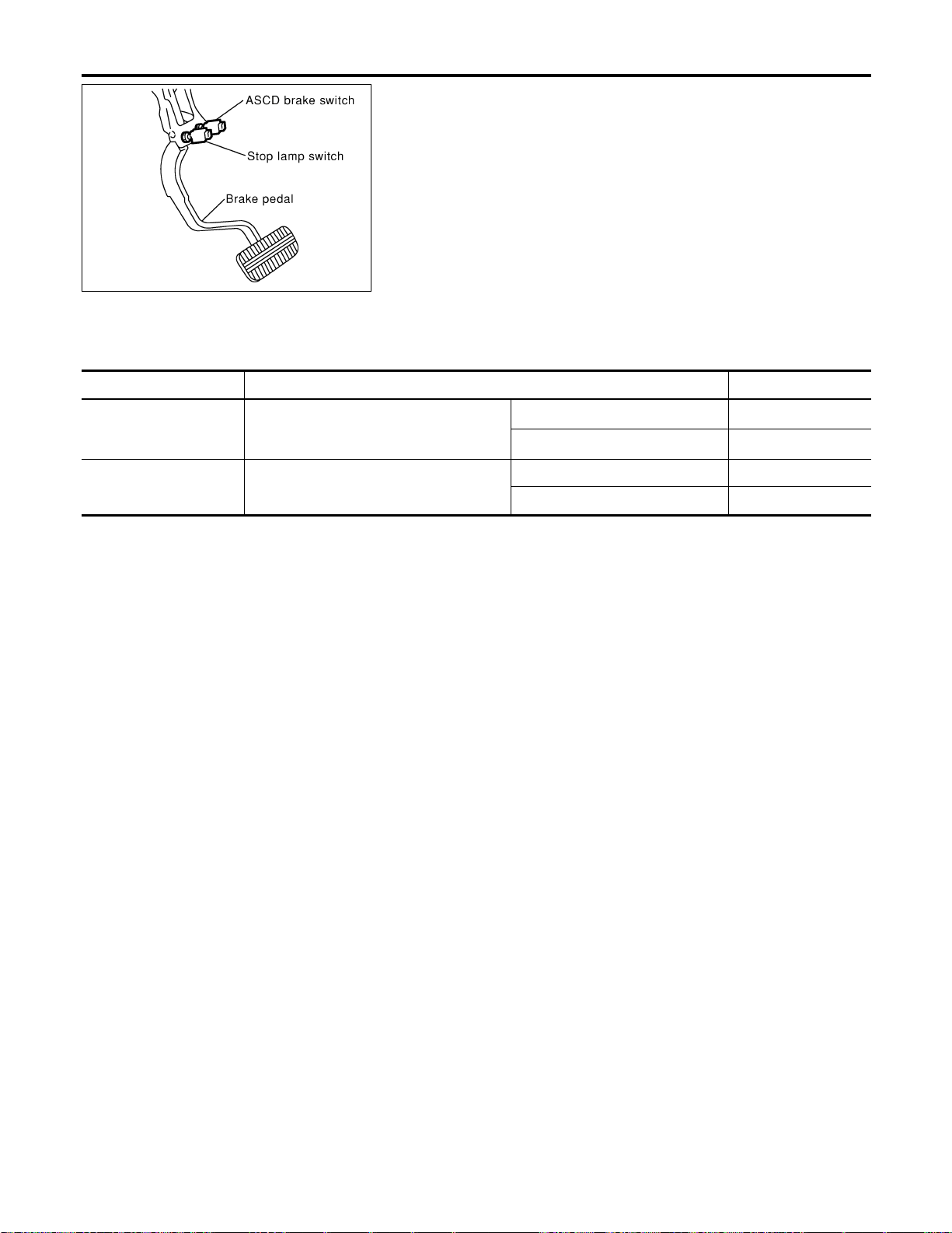
SEC009D
Component Description
NFEC1232
When depressing the brake pedal, ASCD brake switch is turned
OFF and stop lamp switch is turned ON.
ECM detects the state of the brake pedal by this two kinds of input
(ON/OFF signal).
Refer to EC-53 for the ASCD function.
CONSULT-II Reference Value in Data Monitor
Mode
NFEC1233
CONSULT-II Reference Value in Data Monitor Mode Specification data are reference values.
MONITOR ITEM CONDITION SPECIFICATION
BRAKE SW 1
(ASCD brake switch)
I Ignition switch: ON
I Shift lever:
Except “N” and “P” position
I Brake pedal fully released ON
I Brake pedal depressed OFF
BRAKE SW 2
(Stop lamp switch)
I Ignition switch: ON
I Brake pedal fully released OFF
I Brake pedal depressed ON
ASCD BRAKE SWITCH
Component Description
EC-728
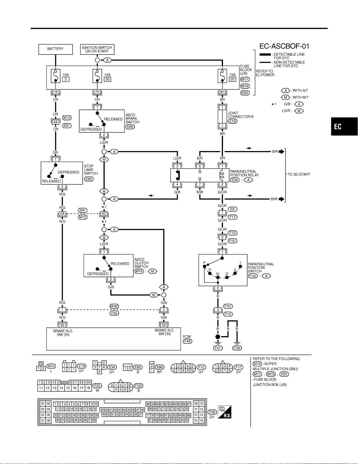
Wiring Diagram
NFEC1237
MEC694D
GI
MA
EM
LC
FE
CL
MT
AT
AX
SU
BR
ST
RS
BT
HA
SC
EL
IDX
ASCD BRAKE SWITCH
Wiring Diagram
EC-729

Specification data are reference values and are measured between each terminal and ground.
CAUTION:
Do not use ECM ground terminals when measuring input/output voltage. Doing so may result in dam-
age to the ECM’s transistor. Use a ground other than ECM terminals, such as the ground.
TERMI-
NAL
NO.
WIRE
COLOR
ITEM CONDITION DATA (DC Voltage)
55 R/G Stop lamp switch
[Ignition switch “ON”]
I Brake pedal is fully released
Approximately 0V
[Ignition switch “ON”]
I Brake pedal is depressed
BATTERY VOLTAGE
(11 - 14V)
59 G/B ASCD brake switch
[Ignition switch “ON”]
I Brake pedal is fully released
I Clutch pedal is fully released (M/T models)
BATTERY VOLTAGE
(11 - 14V)
[Ignition switch “ON”]
I Brake pedal is depressed
I Clutch pedal is fully depressed (M/T models)
Approximately 0V
ASCD BRAKE SWITCH
Wiring Diagram (Cont’d)
EC-730
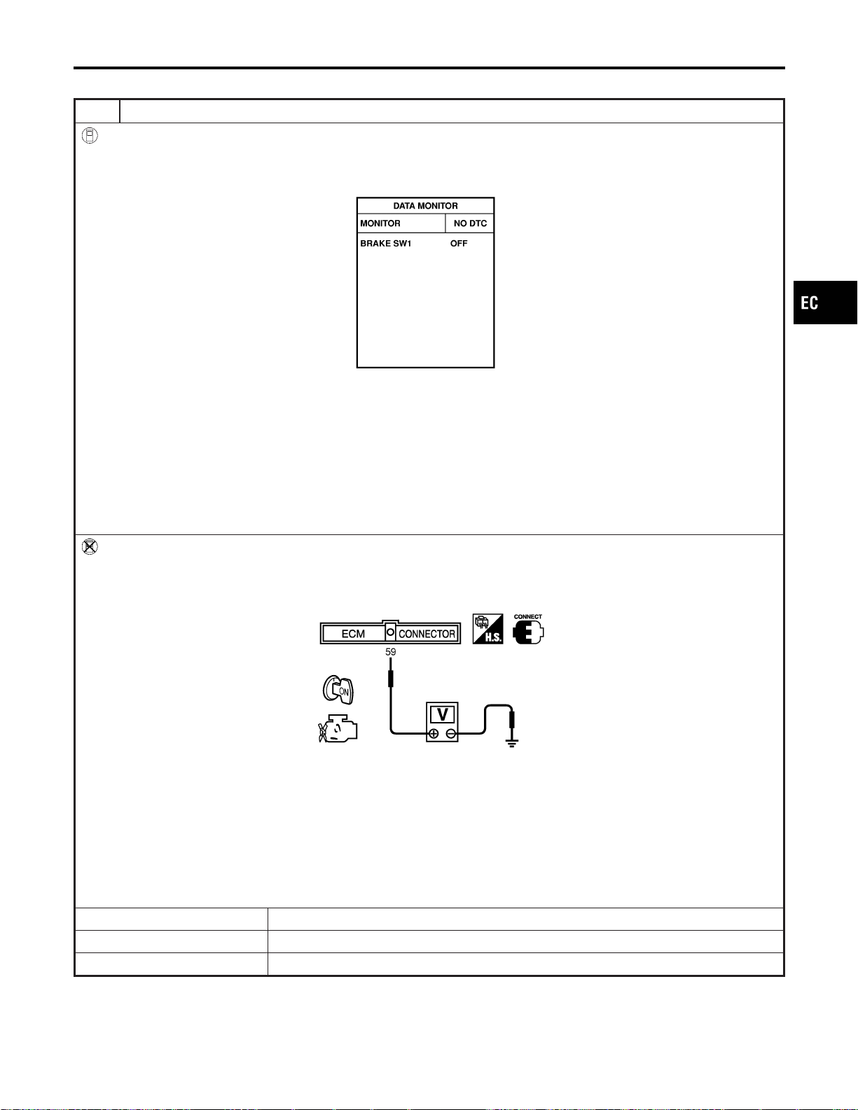
Diagnostic Procedure
NFEC1238
1 CHECK OVERALL FUNCTION-I
With CONSULT-II
1. Turn ignition switch “ON”.
2. Select “BRAKE SW1” in “DATA MONITOR” mode with CONSULT-II.
3. Check the indication of “BRAKE SW1” under the following conditions.
SEC011D
A/T models
When brake pedal is depressed or A/T selector lever is in “N” or “P” range:
BRAKE SW1 OFF
When brake pedal is released and A/T selector lever is not “N” or “P” range:
BRAKE SW1 ON
M/T models
When clutch pedal or brake pedal is depressed:
BRAKE SW1 OFF
When clutch pedal and brake pedal are released:
BRAKE SW1 ON
Without CONSULT-II
1. Turn ignition switch “ON”.
2. Check voltage between ECM terminal 59 and ground under the following conditions.
SEC012D
When brake or clutch pedal is depressed (M/T), or when brake pedal is depressed or A/T selector lever is in “N” or “P”
range (A/T):
Approx. 0V
When brake and clutch pedal are released (M/T), or when both brake pedal is released and A/T selector lever is not in
“N” or “P” range (A/T):
Battery voltage should exist.
Refer to Wiring Diagram.
OK or NG
OK © GO TO 2.
NG © A/T MODELS: GO TO 3.
NG © M/T MODELS: GO TO 19.
GI
MA
EM
LC
FE
CL
MT
AT
AX
SU
BR
ST
RS
BT
HA
SC
EL
IDX
ASCD BRAKE SWITCH
Diagnostic Procedure
EC-731
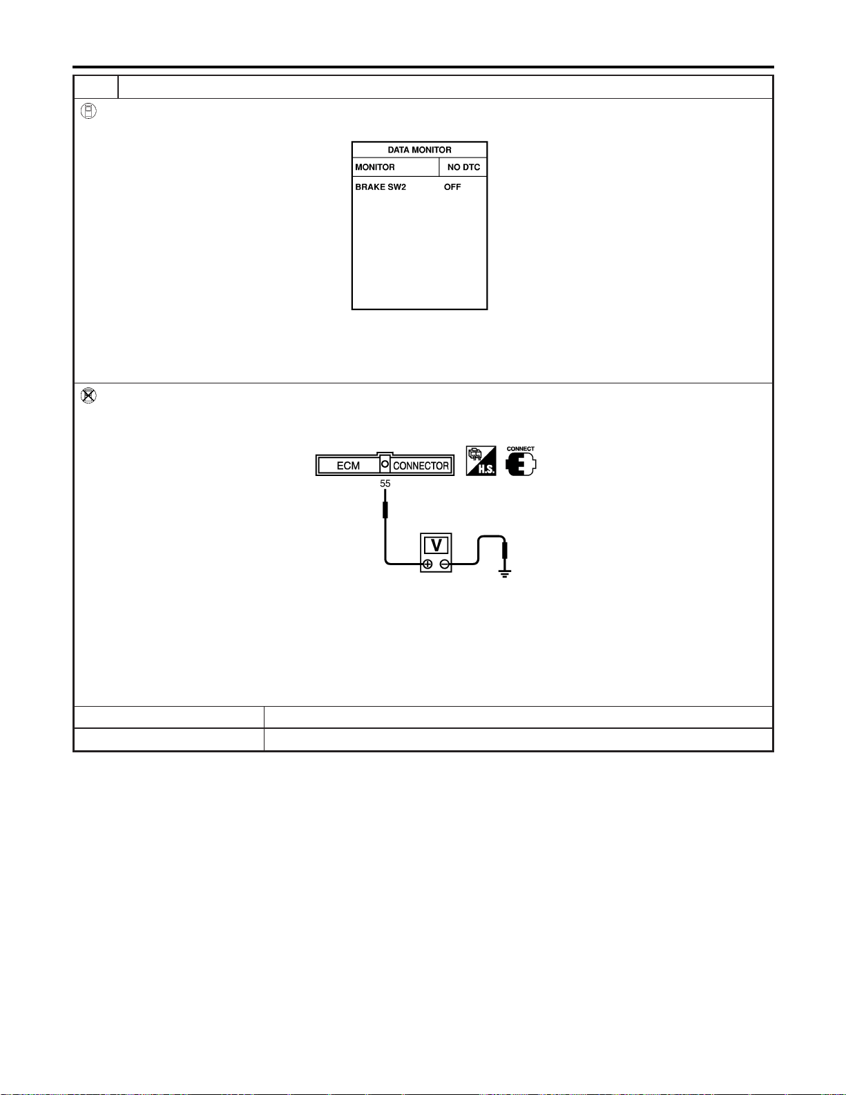
2 CHECK OVERALL FUNCTION-II
With CONSULT-II
See “BRAKE SW2” indication in “DATA MONITOR” mode.
SEC013D
When brake pedal is released:
BRAKE SW2 OFF
When brake pedal is depressed:
BRAKE SW2 ON
Without CONSULT-II
Check voltage between ECM terminal 55 and ground under the following conditions.
SEC014D
When brake pedal is released:
Approx. 0V
When brake pedal is depressed:
Battery voltage should exist.
Refer to Wiring Diagram.
OK or NG
OK © GO TO 33.
NG © GO TO 28.
ASCD BRAKE SWITCH
Diagnostic Procedure (Cont’d)
EC-732
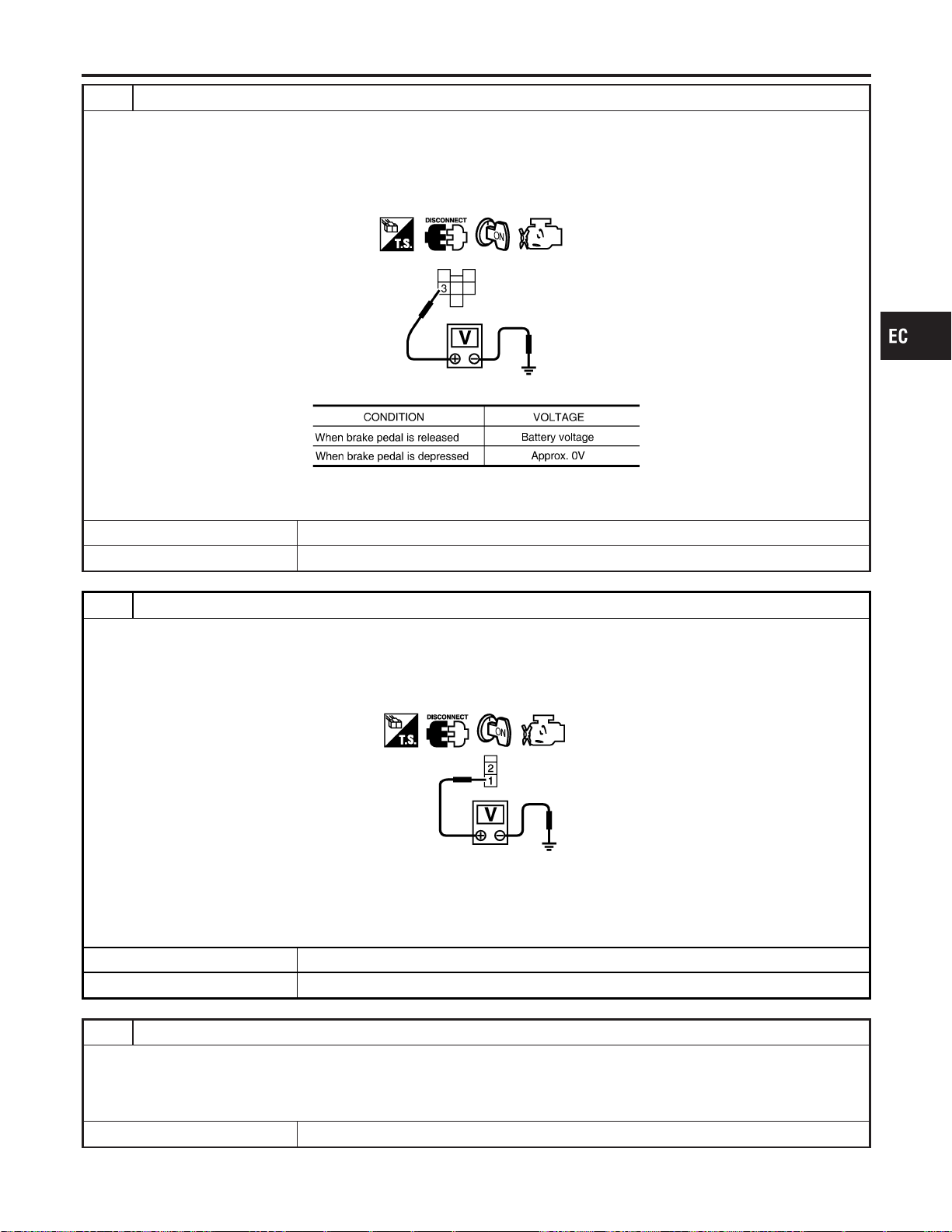
3 CHECK ASCD BRAKE SWITCH CIRCUIT-I
1. Turn ignition switch “OFF”.
2. Disconnect park/neutral position relay harness connector.
3. Turn ignition switch “ON”.
4. Check voltage between park/neutral position relay terminal 3 and ground under the following conditions.
SEC209D
MTBL1259
OK or NG
OK © GO TO 8.
NG © GO TO 4.
4 CHECK ASCD BRAKE SWITCH POWER SUPPLY CIRCUIT
1. Turn ignition switch “OFF”.
2. Disconnect ASCD brake switch harness connector.
3. Turn ignition switch “ON”.
4. Check voltage between ASCD brake switch terminal 1 and ground with CONSULT-II or tester.
PBIB0857E
Voltage: Battery voltage
OK or NG
OK © GO TO 6.
NG © GO TO 5.
5 DETECT MALFUNCTIONING PART
Check the following.
I Fuse block (J/B) connector E83
I 10A fuse
I Harness for open or short between ASCD brake switch and fuse
© Repair open circuit or short to ground or short to power in harness or connectors.
GI
MA
EM
LC
FE
CL
MT
AT
AX
SU
BR
ST
RS
BT
HA
SC
EL
IDX
ASCD BRAKE SWITCH
Diagnostic Procedure (Cont’d)
EC-733
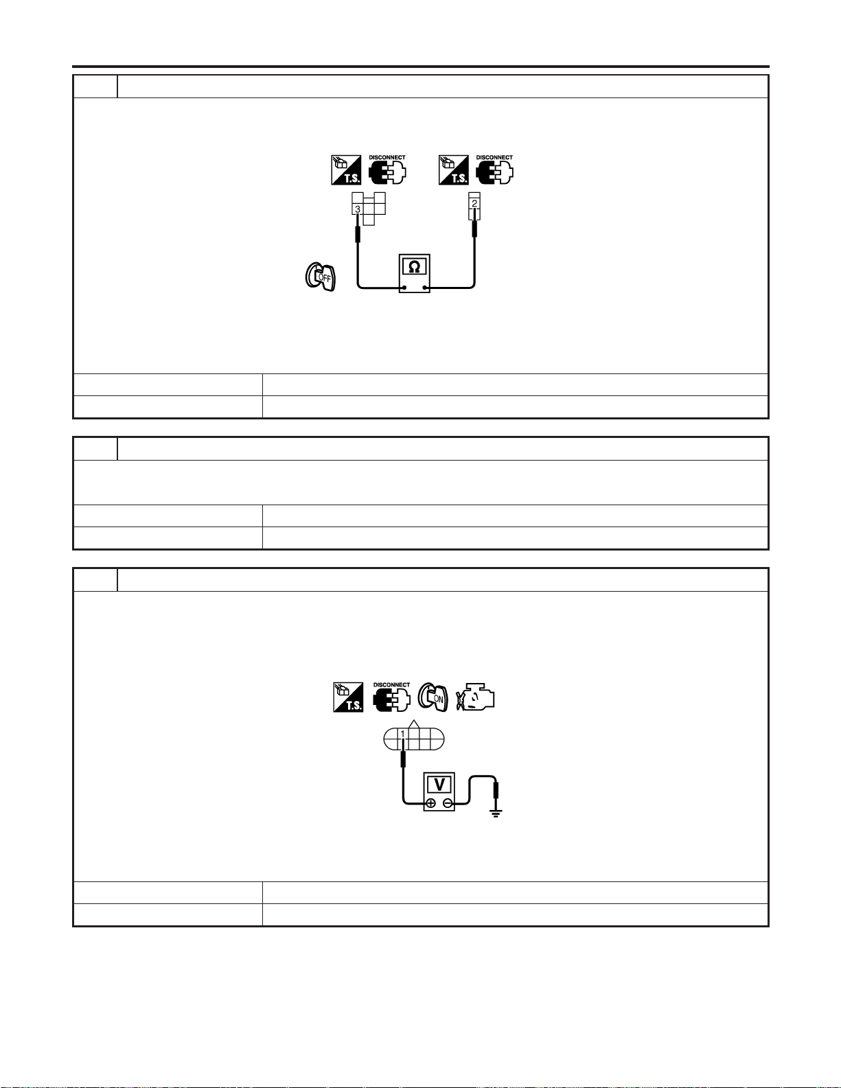
6 CHECK ASCD BRAKE SWITCH INPUT SIGNAL CIRCUIT FOR OPEN AND SHORT
1. Turn ignition switch “OFF”.
2. Check continuity between ASCD brake switch terminal 2 and park/neutral position relay terminal 3.
SEC213D
Continuity should exist.
3. Also check harness for short to ground and short to power.
OK or NG
OK © GO TO 7.
NG © Repair open circuit or short to ground or short to power in harness or connectors.
7 CHECK ASCD BRAKE SWITCH
Refer to “Component Inspection”, EC-661.
OK or NG
OK © GO TO 8.
NG © Replace ASCD brake switch.
8 CHECK PARK/NEUTRAL POSITION (PNP) RELAY CIRCUIT
1. Turn ignition switch “OFF”.
2. Disconnect park/neutral position switch harness connector.
3. Turn ignition switch “ON”.
4. Check voltage between park/neutral position (PNP) switch terminal 1 and ground with CONSULT-II or tester.
SEC214D
Voltage: Battery voltage
OK or NG
OK © GO TO 13.
NG © GO TO 9.
ASCD BRAKE SWITCH
Diagnostic Procedure (Cont’d)
EC-734
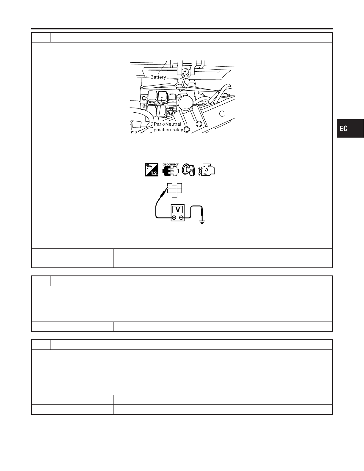
9 CHECK PARK/NEUTRAL POSITION (PNP) RELAY POWER SUPPLY CIRCUIT
1. Turn ignition switch “OFF”.
2. Disconnect park/neutral position (PNP) relay.
SEC018D
3. Turn ignition switch “ON”.
4. Check voltage between park/neutral position (PNP) relay terminal 1 and ground with CONSULT-II or tester.
SEC019D
Voltage: Battery voltage
OK or NG
OK © GO TO 11.
NG © GO TO 10.
10 DETECT MALFUNCTIONING PART
Check the following.
I Fuse block (J/B) connector E83
I 15A fuse
I Joint connector-8
I Harness for open or short between park/neutral position (PNP) relay and fuse
© Repair open circuit or short to ground in harness or connectors.
11 CHECK PARK/NEUTRAL POSITION RELAY CIRCUIT FOR OPEN AND SHORT
1. Turn ignition switch “OFF”.
2. Check continuity between park/neutral position (PNP) relay terminal 2 and park/neutral position switch terminal 1.
Refer to Wiring Diagram.
Continuity should exist.
3. Also check harness for short to ground and short to power.
OK or NG
OK © GO TO 13.
NG © GO TO 12.
GI
MA
EM
LC
FE
CL
MT
AT
AX
SU
BR
ST
RS
BT
HA
SC
EL
IDX
ASCD BRAKE SWITCH
Diagnostic Procedure (Cont’d)
EC-735
12 DETECT MALFUNCTIONING PART
Check the following.
I Harness connectors E8, F17
I Harness connectors F10, F151
I Harness for open or short between park/neutral position relay and park/neutral position switch
© Repair open circuit or short to ground or short to power in harness or connectors.
13 CHECK PARK/NEUTRAL POSITION RELAY
Refer to “Component Inspection”, EC-661.
OK or NG
OK © GO TO 28.
NG © Replace park/neutral position relay.
14 CHECK PARK/NEUTRAL POSITION (PNP) SWITCH GROUND CIRCUIT
1. Turn ignition switch “OFF”.
2. Disconnect park/neutral position switch harness connector.
3. Check continuity between park/neutral position (PNP) switch terminal 2 and ground.
Continuity should exist.
4. Also check harness for short to ground and short to power.
OK or NG
OK © GO TO 16.
NG © GO TO 15.
15 DETECT MALFUNCTIONING PART
Check the following.
I Harness connectors F10, F151
I Harness for open or short between park/neutral position (PNP) switch and ground
© Repair open circuit or short to ground or short to power in harness or connectors.
16 CHECK PARK/NEUTRAL POSITION SWITCH
Refer to “Component Inspection”, EC-661.
OK or NG
OK © GO TO 17.
NG © Replace park/neutral position switch.
ASCD BRAKE SWITCH
Diagnostic Procedure (Cont’d)
EC-736
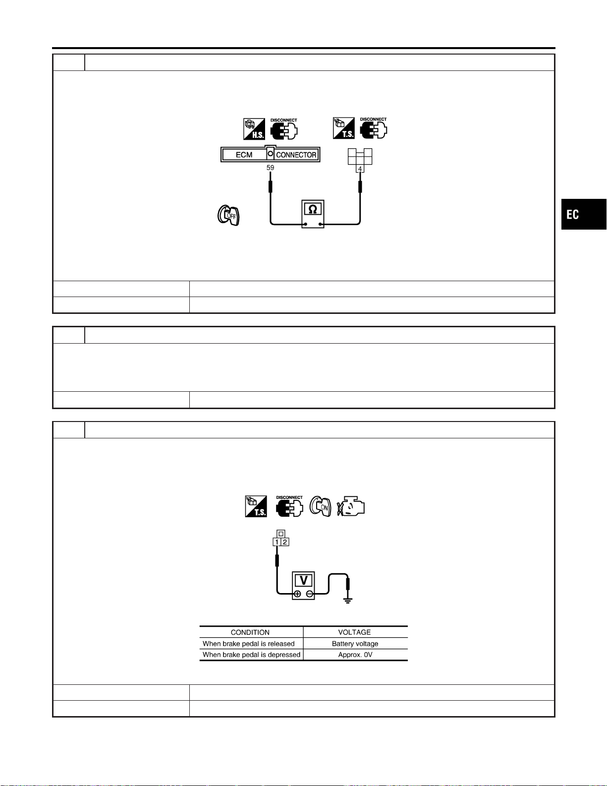
17 CHECK ASCD BRAKE SWITCH INPUT SIGNAL CIRCUIT
1. Turn ignition switch “OFF”.
2. Disconnect ECM harness connector and park/neutral position (PNP) relay harness connector.
3. Check harness continuity between park/neutral position (PNP) relay terminal 4 and ECM terminal 59.
SEC215D
Continuity should exist.
4. Also check harness for short to ground and short to power.
OK or NG
OK © GO TO 28.
NG © GO TO 18.
18 DETECT MALFUNCTIONING PART
Check the following.
I Harness connectors E81, M15
I Harness connectors M162, F55
I Harness for open or short between park/neutral position (PNP) relay and ECM
© Repair open circuit or short to ground or short to power in harness or connectors.
19 CHECK ASCD BRAKE SWITCH CIRCUIT-II
1. Turn ignition switch “OFF”.
2. Disconnect ASCD clutch switch harness connector.
3. Turn ignition switch “ON”.
4. Check voltage between ASCD clutch switch terminal 1 and ground under the following conditions.
PBIB0799E
MTBL1303
OK or NG
OK © GO TO 25.
NG © GO TO 20.
GI
MA
EM
LC
FE
CL
MT
AT
AX
SU
BR
ST
RS
BT
HA
SC
EL
IDX
ASCD BRAKE SWITCH
Diagnostic Procedure (Cont’d)
EC-737
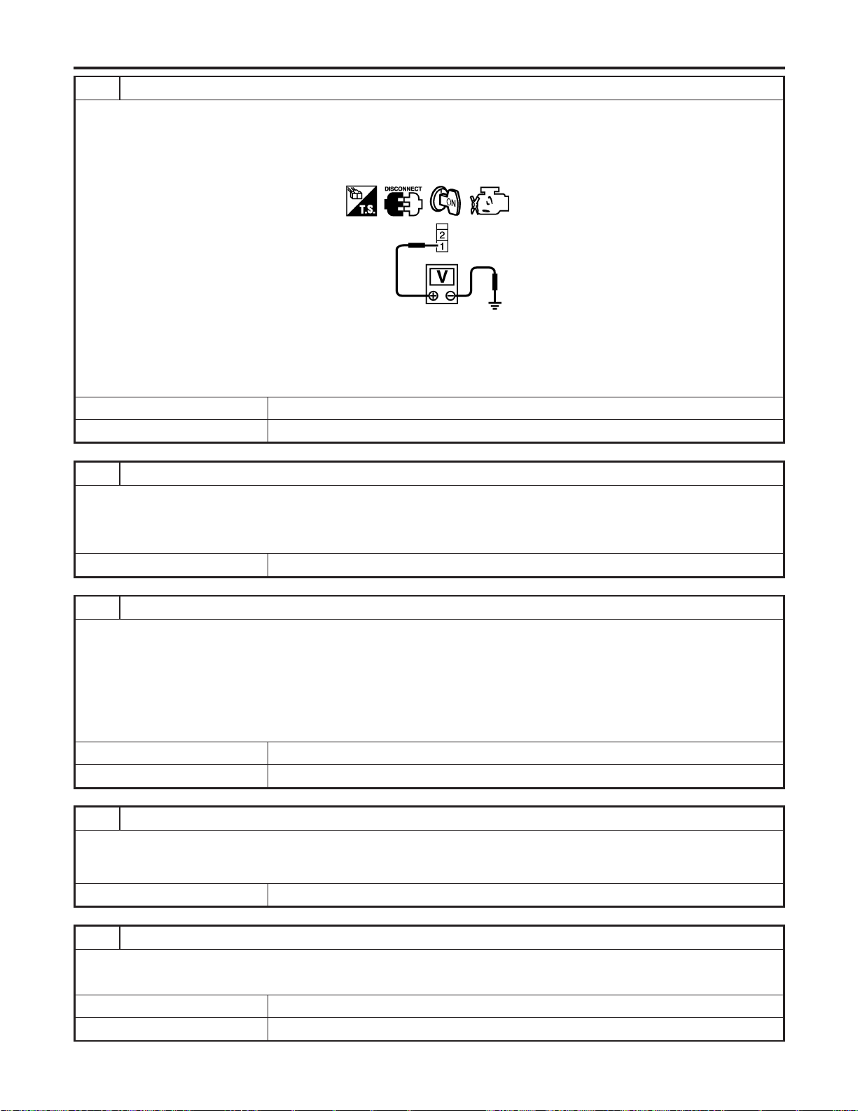
20 CHECK ASCD BRAKE SWITCH POWER SUPPLY CIRCUIT
1. Turn ignition switch “OFF”.
2. Disconnect ASCD brake switch harness connector.
3. Turn ignition switch “ON”.
4. Check voltage between ASCD brake switch terminal 1 and ground with CONSULT-II or tester.
PBIB0857E
Voltage: Battery voltage
OK or NG
OK © GO TO 22.
NG © GO TO 21.
21 DETECT MALFUNCTIONING PART
Check the following.
I Fuse block (J/B) connector E83
I 10A fuse
I Harness for open or short between ASCD brake switch and fuse
© Repair open circuit or short to ground or short to power in harness or connectors.
22 CHECK ASCD BRAKE SWITCH INPUT SIGNAL CIRCUIT FOR OPEN AND SHORT
1. Turn ignition switch “OFF”.
2. Disconnect ASCD clutch switch harness connector.
3. Check continuity between ASCD brake switch terminal 2 and ASCD clutch switch terminal 1.
Refer to Wiring Diagram.
Continuity should exist.
4. Also check harness for short to ground and short to power.
OK or NG
OK © GO TO 24.
NG © GO TO 23.
23 DETECT MALFUNCTIONING PART
Check the following.
I Harness connectors E81, M15
I Harness for open or short between ASCD brake switch and ASCD clutch switch
© Repair open circuit or short to ground or short to power in harness or connectors.
24 CHECK ASCD BRAKE SWITCH
Refer to “Component Inspection”, EC-661.
OK or NG
OK © GO TO 25.
NG © Replace ASCD brake switch.
ASCD BRAKE SWITCH
Diagnostic Procedure (Cont’d)
EC-738
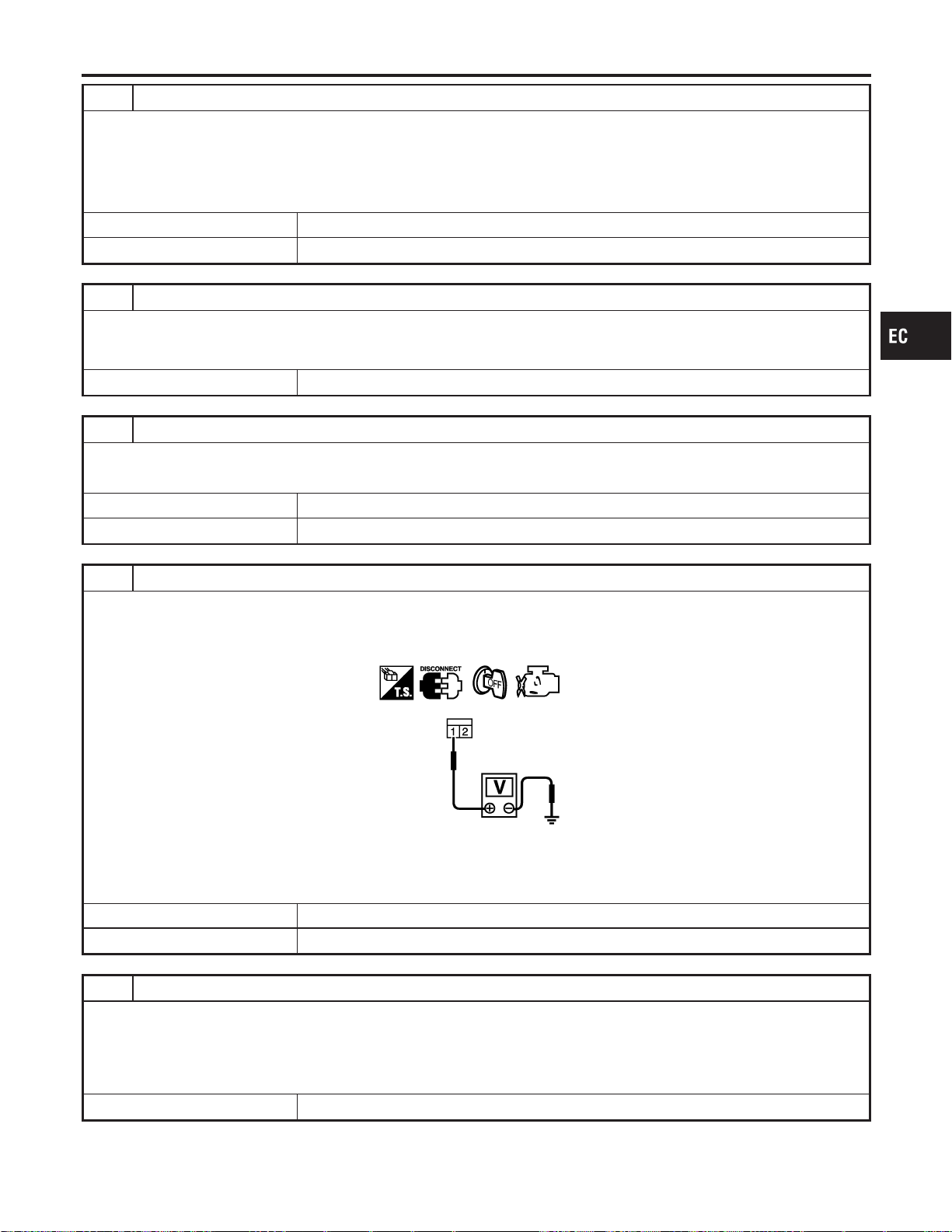
25 CHECK ASCD CLUTCH SWITCH CIRCUIT FOR OPEN AND SHORT
1. Turn ignition switch “OFF”.
2. Check continuity between ASCD clutch switch terminal 2 and ECM terminal 59.
Continuity should exist.
3. Also check harness for short to ground and short to power.
OK or NG
OK © GO TO 27.
NG © GO TO 26.
26 DETECT MALFUNCTIONING PART
Check the following.
I Harness connectors M162, F55
I Harness for open or short between ASCD clutch switch and ECM
© Repair open circuit or short to ground or short to power in harness or connectors.
27 CHECK ASCD CLUTCH SWITCH
Refer to “Component Inspection”, EC-661.
OK or NG
OK © GO TO 28.
NG © Replace ASCD clutch switch.
28 CHECK STOP LAMP SWITCH POWER SUPPLY CIRCUIT
1. Turn ignition switch “OFF”.
2. Disconnect stop lamp switch harness connector.
3. Check voltage between stop lamp switch terminal 1 and ground with CONSULT-II or tester.
PBIB0117E
Voltage: Battery voltage
OK or NG
OK © GO TO 30.
NG © GO TO 29.
29 DETECT MALFUNCTIONING PART
Check the following.
I Fuse block (J/B) connector M17
I 15A fuse
I Harness connectors M15, E81
I Harness for open or short between stop lamp switch and fuse
© Repair open circuit or short to ground in harness or connectors.
GI
MA
EM
LC
FE
CL
MT
AT
AX
SU
BR
ST
RS
BT
HA
SC
EL
IDX
ASCD BRAKE SWITCH
Diagnostic Procedure (Cont’d)
EC-739
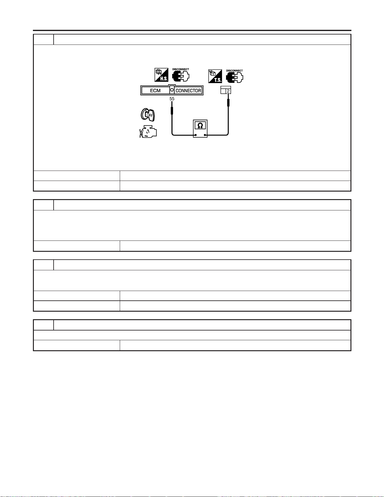
30 CHECK STOP LAMP SWITCH INPUT SIGNAL CIRCUIT FOR OPEN AND SHORT
1. Disconnect ECM harness connector.
2. Check harness continuity between stop lamp switch terminal 2 and ECM terminal 55.
SEC216D
Continuity should exist
3. Also check harness for short to ground and short to power.
OK or NG
OK © GO TO 32.
NG © GO TO 31.
31 DETECT MALFUNCTIONING PART
Check the following.
I Harness connectors M15, E81
I Harness connectors M162, F55
I Harness for open or short between stop lamp switch and ECM
© Repair open circuit or short to ground or short to power in harness or connectors.
32 CHECK STOP LAMP SWITCH
Refer to “Component Inspection”, EC-661.
OK or NG
OK © GO TO 33.
NG © Replace stop lamp switch.
33 CHECK INTERMITTENT INCIDENT
Refer to “TROUBLE DIAGNOSIS FOR INTERMITTENT INCIDENT”, EC-156.
© INSPECTION END
ASCD BRAKE SWITCH
Diagnostic Procedure (Cont’d)
EC-740
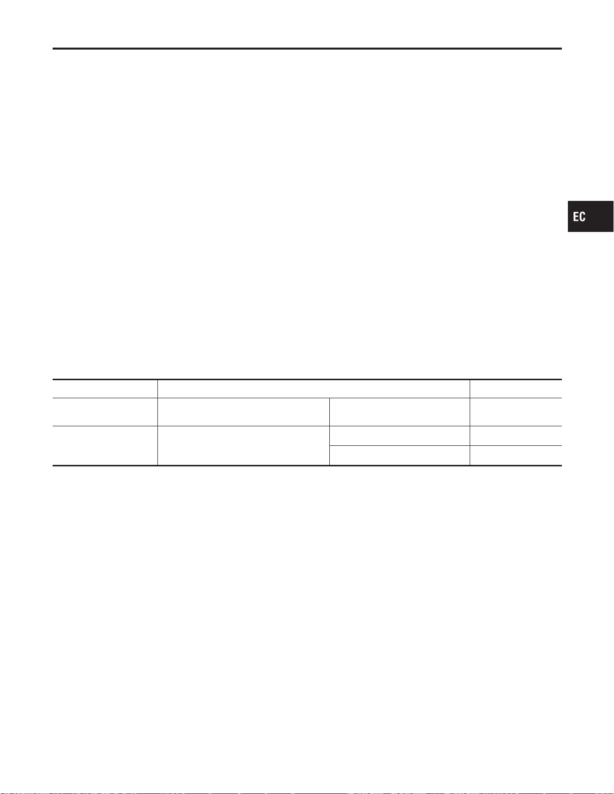
Component Description
NFEC1240
ASCD indicator lamp illuminatesto indicateASCD operation status.
Lamp has two indicators, CRUISE and SET, and is integrated in
combination meter.
CRUISE indicator illuminates when CRUISE switch on steering
switch is turned ON to indicate that ASCD system is ready for
operation.
SET indicator illuminates when following conditions are met.
CRUISE indicator illuminates, and SET switch on steering switch
is turned ON while vehicle speed is within range of ASCD setting.
SET indicator remains lit during ASCD control. Refer to EC-53 for
ASCD functions.
CONSULT-II Reference Value in Data Monitor
Mode
NFEC1474
Specification data are reference values.
MONITOR ITEM CONDITION SPECIFICATION
CRUISE LAMP I Ignition switch: ON
I CRUISE switch is depressed at
first time , second time.
ON , OFF
SET LAMP
I When vehicle speed is between 40 km/h
(25 MPH) to 144 km/h (89 MPH), and
CRUISE switch is ON.
I COAST/SET switch pressed ON
I ASCD control is canceled. OFF
GI
MA
EM
LC
FE
CL
MT
AT
AX
SU
BR
ST
RS
BT
HA
SC
EL
IDX
ASCD INDICATOR LAMP
Component Description
EC-741
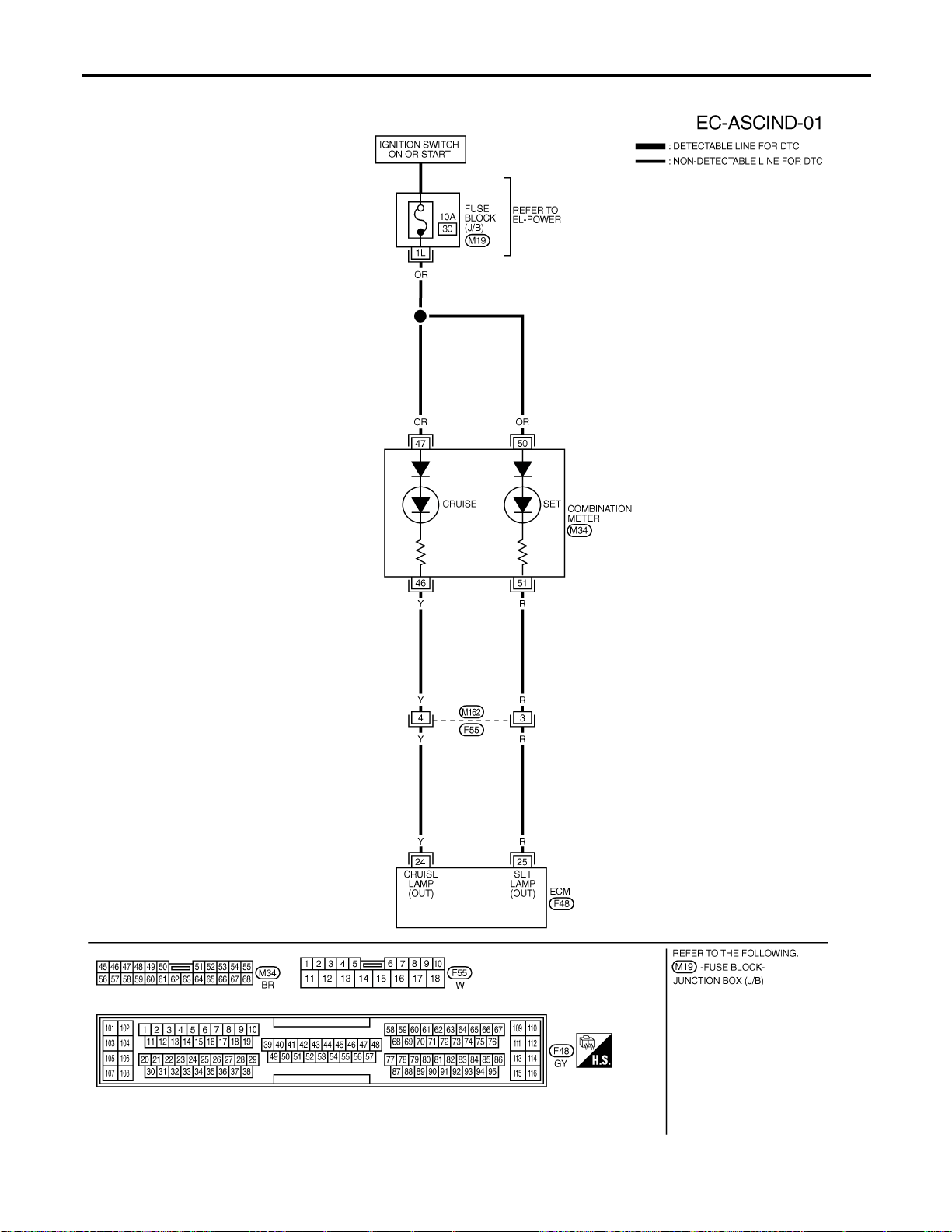
Wiring Diagram
NFEC1242
MEC692D
ASCD INDICATOR LAMP
Wiring Diagram
EC-742
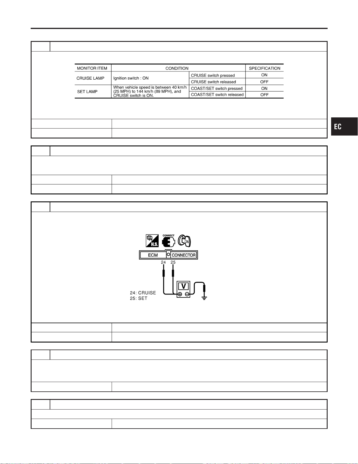
Diagnostic Procedure
NFEC1243
1 CHECK OVERALL FUNCTION
Check ASCD indicator under the following conditions.
MTBL1260
OK or NG
OK © INSPECTION END
NG © GO TO 2.
2 CHECK COMBINATION METER OPERATION
Check that combination meter operates normally.
OK or NG
OK © GO TO 3.
NG © Check combination meter circuit. Refer to EL-121.
3 CHECK INDICATOR CIRCUIT
1. Turn ignition switch “ON”.
2. Check voltage between ECM terminals 24, 25 and ground with CONSULT-II or tester.
SEC028D
Battery voltage should exist.
OK or NG
OK © GO TO 5.
NG © GO TO 4.
4 DETECT MALFUNCTIONING PART
Check the following.
I Harness connectors F55, M162
I Harness for open or short between combination meter and ECM
© Repair open circuit or short to ground or short to power in harness or connectors.
5 CHECK INTERMITTENT INCIDENT
Refer to “TROUBLE DIAGNOSIS FOR INTERMITTENT INCIDENT”, EC-156.
© INSPECTION END
GI
MA
EM
LC
FE
CL
MT
AT
AX
SU
BR
ST
RS
BT
HA
SC
EL
IDX
ASCD INDICATOR LAMP
Diagnostic Procedure
EC-743
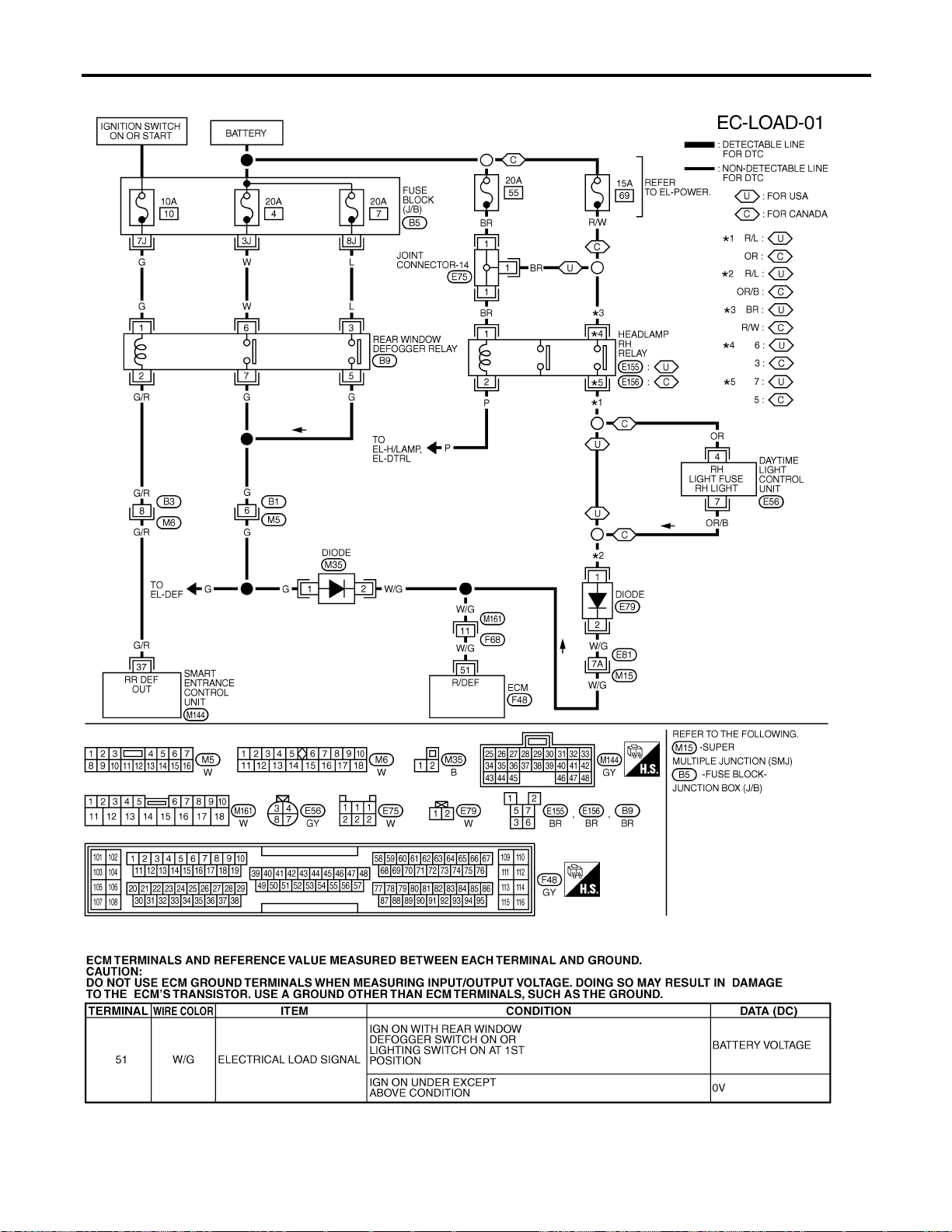
Wiring Diagram
NFEC0604
MEC518D
SEF642XC
ELECTRICAL LOAD SIGNAL
Wiring Diagram
EC-744
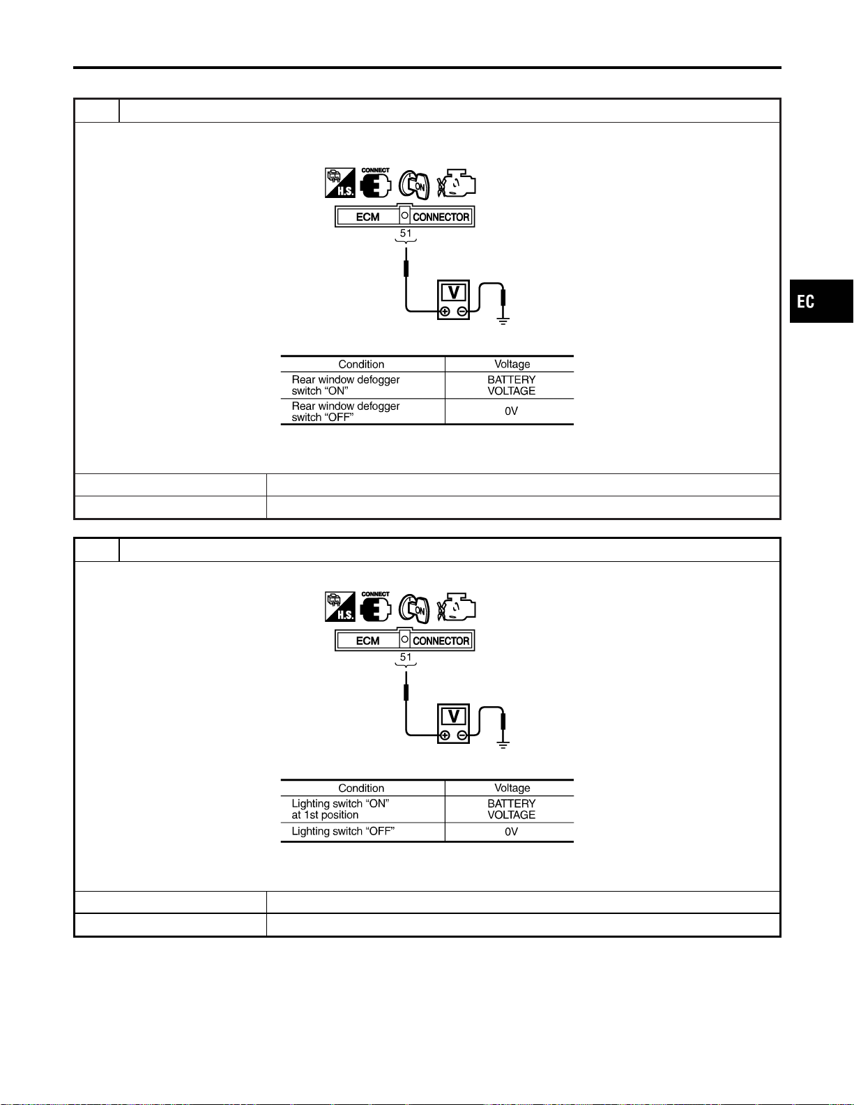
Diagnostic Procedure
NFEC0605
1 CHECK LOAD SIGNAL CIRCUIT OVERALL FUNCTION-I
1. Turn ignition switch “ON”.
2. Check voltage between ECM terminal 51 and ground under the following conditions.
SEC090D
MTBL1165
OK or NG
OK © GO TO 2.
NG © GO TO 3.
2 CHECK LOAD SIGNAL CIRCUIT OVERALL FUNCTION-II
Check voltage between ECM terminal 51 and ground under the following conditions.
SEC090D
MTBL1166
OK or NG
OK © INSPECTION END
NG © GO TO 7.
GI
MA
EM
LC
FE
CL
MT
AT
AX
SU
BR
ST
RS
BT
HA
SC
EL
IDX
ELECTRICAL LOAD SIGNAL
Diagnostic Procedure
EC-745
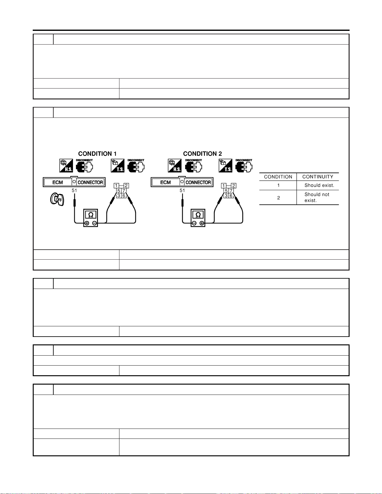
3 CHECK REAR WINDOW DEFOGGER FUNCTION
1. Start engine.
2. Turn “ON” the rear window defogger switch.
3. Check the rear windshield. Is the rear windshield heated up?
YesorNo
Yes © GO TO 4.
No © Refer to EL-167, “Rear Window Defogger”.
4 CHECK REAR WINDOW DEFOGGER INPUT SIGNAL CIRCUIT FOR OPEN OR SHORT
1. Stop engine.
2. Disconnect ECM harness connector.
3. Disconnect rear window defogger relay.
4. Check harness continuity between ECM terminal 51 and rear window defogger relay terminal 5 and 7.
SEC125D
5. Also check harness for short to ground and short to power.
OK or NG
OK © GO TO 6.
NG © GO TO 5.
5 DETECT MALFUNCTIONING PART
Check the following.
I Harness connectors B1, M5
I Harness connectors M161, F68
I Diode M35
I Harness for open and short between ECM and rear window defogger relay
© Repair open circuit or short to ground or short to power in harness or connectors.
6 CHECK INTERMITTENT INCIDENT
Perform “TROUBLE DIAGNOSIS FOR INTERMITTENT INCIDENT”, EC-156.
© INSPECTION END
7 CHECK HEADLAMP FUNCTION
1. Start engine.
2. Turn the lighting switch “ON” at 1st position with high beam.
3. Check that headlamps are illuminated.
OK or NG
OK © GO TO 8.
NG © Refer to EL-37, “HEADLAMP (FOR USA)” or “EL-51, “HEADLAMP (FOR CANADA) —
DAYTIME LIGHT SYSTEM”.
ELECTRICAL LOAD SIGNAL
Diagnostic Procedure (Cont’d)
EC-746
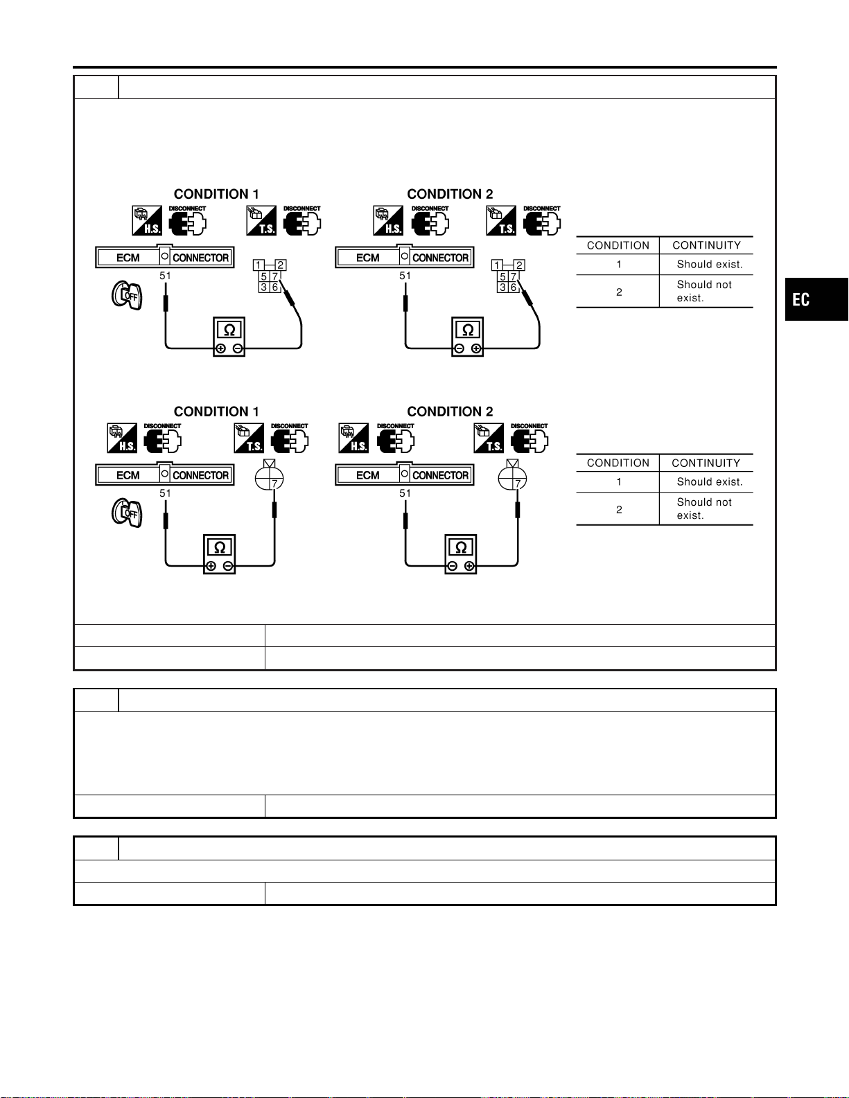
8 CHECK HEADLAMP INPUT SIGNAL CIRCUIT FOR OPEN OR SHORT
1. Stop engine.
2. Disconnect ECM harness connector.
3. Disconnect headlamp RH relay (Models for USA), daytime light control unit harness connector (Models for Canada).
4. Check harness continuity between ECM terminal 51 and headlamp LH relay terminal 7 under the following conditions.
(Models for USA)
SEC126D
5. Check harness continuity between ECM terminal 51 and daytime light control unit terminal 7 under the following condi-
tions.(Model for Canada)
SEC127D
6. Also check harness for short to ground and short to power.
OK or NG
OK © GO TO 10.
NG © GO TO 9.
9 DETECT MALFUNCTIONING PART
Check the following.
I Harness connectors E81, M15
I Harness connectors M161, F68
I Diode E79
I Harness for open and short between ECM and headlamp RH relay or daytime light control unit
© Repair open circuit or short to ground or short to power in harness or connectors.
10 CHECK INTERMITTENT INCIDENT
Perform “TROUBLE DIAGNOSIS FOR INTERMITTENT INCIDENT”, EC-156.
© INSPECTION END
GI
MA
EM
LC
FE
CL
MT
AT
AX
SU
BR
ST
RS
BT
HA
SC
EL
IDX
ELECTRICAL LOAD SIGNAL
Diagnostic Procedure (Cont’d)
EC-747
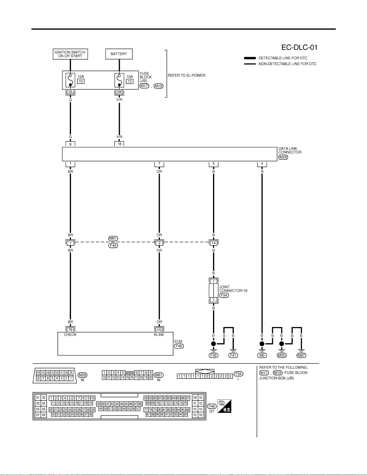
Wiring Diagram
NFEC0407
MEC697D
DATA LINK CONNECTORS
Wiring Diagram
EC-748
Fuel Pressure Regulator
NFEC0408
Fuel pressure at idling kPa (kg/cm
2
, psi) Approximately 350 (3.7, 51)
Idle Speed and Ignition Timing
NFEC0409
Target idle speed*1
No-load*2 (in “P” or N” position)
M/T: 625±50 rpm
A/T: 675±50 rpm
Air conditioner: ON In “P” or N” position 825 rpm or more
Ignition timing*1 In “P” or N” position 15°±5° BTDC
*1: Throttle position sensor harness connector connected
*2: Under the following conditions:
I Air conditioner switch: OFF
I Electric load: OFF (Lights, heater fan & rear window defogger)
I Steering wheel: Kept in straight-ahead position
Mass Air Flow Sensor
NFEC0411
Supply voltage Battery voltage (11 - 14)V
Output voltage at idle 1.1 - 1.5*V
Mass air flow (Using CONSULT-II or GST)
2.0 - 6.0 g·m/sec at idle*
7.0 - 20.0 g·m/sec at 2,500 rpm*
*: Engine is warmed up to normal operating temperature and running under no-load.
Engine Coolant Temperature Sensor
NFEC0412
Temperature °C (°F) Resistance kΩ
20 (68) 2.1 - 2.9
50 (122) 0.68 - 1.00
90 (194) 0.236 - 0.260
Heated Oxygen Sensor 1 Heater
NFEC0414
Resistance [at 25°C (77°F)] 2.3 - 4.3Ω
Fuel Pump
NFEC0415
Resistance [at 25°C (77°F)] 0.2 - 5.0Ω
Injector
NFEC0417
Resistance [at 20°C (68°F)] 13.5 - 17.5Ω
Calculated Load Value
NFEC0420
Calculated load value % (Using CONSULT-II or GST)
At idle 10-35
At 2,500 rpm 10-35
Intake Air Temperature Sensor
NFEC0421
Temperature °C (°F) Resistance kΩ
20 (68) 2.1 - 2.9
80 (176) 0.27 - 0.38
GI
MA
EM
LC
FE
CL
MT
AT
AX
SU
BR
ST
RS
BT
HA
SC
EL
IDX
SERVICE DATA AND SPECIFICATIONS (SDS)
Fuel Pressure Regulator
EC-749

Heated Oxygen Sensor 2 Heater
NFEC0422
Resistance [at 25°C (77°F)] 2.3 - 4.3Ω
Fuel Tank Temperature Sensor
NFEC0424
Temperature °C (°F) Resistance kΩ
20 (68) 2.3 - 2.7
50 (122) 0.79 - 0.90
Throttle Control Motor
NFEC1332
Resistance [at 25°C (77°F)] Approximately1-15Ω
Crankshaft Position Sensor (POS)
NFEC1414
Refer to “Component Inspection”, EC-336.
Camshaft Position Sensor (PHASE)
NFEC0639
Refer to “Component Inspection”, EC-345.
SERVICE DATA AND SPECIFICATIONS (SDS)
Heated Oxygen Sensor 2 Heater
EC-750