Loading ...
Loading ...
Loading ...
810
Users Manual
3-6
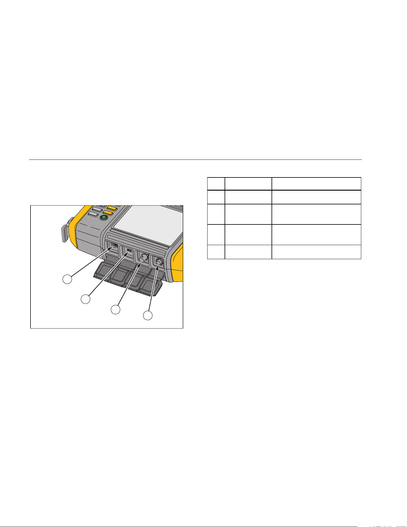
Accessory Connectors
Figure 3-2 shows the connector panel of the Tester.
Table 3-3 is a list of descriptions for each connector on
the Tester.
1
2
3
4
gbk01.eps
Figure 3-2. Accessory Connectors
Table 3-3. Accessory Connectors
Item Connector Description
Tachometer Connects the Tachometer
USB
Connects the Tester to the PC
using a USB cable
Sensor
Optional connector for single
axis Sensor
Sensor Connects the triaxial Sensor
1.888.610.7664 sales@GlobalTestSupply.com
Fluke-Direct.com
Loading ...
Loading ...
Loading ...