
January 2010, Rev. 2, 5/15
© 2010-2015 Fluke Corporation. All rights reserved. Specifications are subject to change without notice.
All product names are trademarks of their respective companies.
810
Vibration Tester
Users Manual
1.888.610.7664 sales@GlobalTestSupply.com
Fluke-Direct.com

LIMITED WARRANTY AND LIMITATION OF LIABILITY
Your Fluke Vibration Tester is warranted to be free from defects in material and workmanship under normal use and service for three years
from the date of shipment to you. The same warranty applies to the Tachometer and the Sensor but for one year from the date of shipment.
Parts, product repairs, and services are warranted for 90 days. This warranty extends only to the original buyer or end-user customer of a
Fluke authorized reseller, and does not apply to fuses, disposable batteries, or to any product which, in Fluke's opinion, has been misused,
altered, neglected, contaminated, or damaged by accident or abnormal conditions of operation or handling. Fluke warrants that software will
operate substantially in accordance with its functional specifications for 90 days and that it has been properly recorded on non-defective
media. Fluke does not warrant that software will be error free or operate without interruption.
Fluke authorized resellers shall extend this warranty on new and unused products to end-user customers only but have no authority to
extend a greater or different warranty on behalf of Fluke. Warranty support is available only if product is purchased through a Fluke
authorized sales outlet or Buyer has paid the applicable international price. Fluke reserves the right to invoice Buyer for importation costs of
repair/replacement parts when product purchased in one country is submitted for repair in another country.
Fluke's warranty obligation is limited, at Fluke's option, to refund of the purchase price, free of charge repair, or replacement of a defective
product which is returned to a Fluke authorized service center within the warranty period.
To obtain warranty service, contact your nearest authorized service center to obtain return authorization informat
ion, then send the
product to that service center, w
ith a description of the difficulty, postage and insurance prepaid (FOB Destination). Fluke assumes no risk
for damage in transit. Following warranty repair, the product will be returned to Buyer, transportation prepaid (FOB Destination). If Fluke
determines that failure was caused by neglect, misuse, contamination, alteration, accident, or abnormal condition of operation or handling,
including overvoltage failures caused by use outside the product’s specified rating, or normal wear and tear of mechanical components,
Fluke will provide an estimate of repair costs and obtain authorization before commencing the work. Following repair, the product will be
returned to the Buyer transportation prepaid and the Buyer will be billed for the repair and return transportation charges (FOB Shipping
Point).
THIS WARRANTY IS BUYER'S SOLE AND EXCLUSIVE REMEDY AND IS IN LIEU OF ALL OTHER WARRANTIES, EXPRESS OR
IMPLIED, INCLUDING BUT NOT LIMITED TO ANY IMPLIED WARRANTY OF MERCHANTABILITY OR FITNESS FOR A PARTICULAR
PURPOSE. FLUKE SHALL NOT BE LIABLE FOR ANY SPECIAL, INDIRECT, INCIDENTAL OR CONSEQUENTIAL DAMAGES OR
LOSSES, INCLUDING LOSS OF DATA, ARISING FROM ANY CAUSE OR THEORY.
Since some countries or states do not allow limitation of the term of an implied warranty, or exclusion or limitation of incidental or
consequential damages, the limitations and exclusions of this warranty may not apply to every buyer. If any provision of this Warranty is held
invalid or unenforceable by a court or other decision-maker of competent jurisdiction, such holding will not affect the validity or enforceability
of any other provision.
1.888.610.7664 sales@GlobalTestSupply.com
Fluke-Direct.com

i
Table of Contents
Chapter Title Page
1 Overview ....................................................................................................................... 1-1
Introduction .................................................................................................................... 1-3
Features ......................................................................................................................... 1-3
How to Contact ..................................................................................................... 1-4
Safety ............................................................................................................................. 1-4
Rotating Equipment ................................................................................................... 1-5
Tachometer ............................................................................................................... 1-5
Heat Sink ................................................................................................................... 1-6
Symbols ......................................................................................................................... 1-6
Unpack and Inspect........................................................................................................ 1-7
Storage ........................................................................................................................... 1-9
Battery ............................................................................................................................ 1-9
Accessories .................................................................................................................... 1-11
1.888.610.7664 sales@GlobalTestSupply.com
Fluke-Direct.com

810
Users Manual
ii
2 Specifications .............................................................................................................. 2-1
Vibration Tester Specifications ...................................................................................... 2-3
Diagnostic Specifications .......................................................................................... 2-3
Electrical Specifications ............................................................................................ 2-3
General Specifications .............................................................................................. 2-4
Sensor Specifications .................................................................................................... 2-5
Tachometer Specifications ............................................................................................ 2-6
Viewer Software Requirements ..................................................................................... 2-7
3 Getting Started ............................................................................................................. 3-1
Introduction .................................................................................................................... 3-3
Navigation and User Interface ....................................................................................... 3-3
How to Use the Dial .................................................................................................. 3-5
How to Use the Function Softkeys ............................................................................ 3-5
Accessory Connectors ................................................................................................... 3-6
Start the Tester .............................................................................................................. 3-7
Sensor Setup ................................................................................................................. 3-7
Compatible Sensors .................................................................................................. 3-7
How to Connect the Fluke Sensor ............................................................................ 3-8
Sensor Care and Handling ........................................................................................ 3-9
Tachometer Setup ......................................................................................................... 3-9
How to Measure RPM with the Tachometer ............................................................. 3-9
Laser Safety Precautions .......................................................................................... 3-10
How to Access Help ....................................................................................................... 3-11
Instrument Setup ........................................................................................................... 3-11
Self Test .................................................................................................................... 3-11
Settings ..................................................................................................................... 3-12
Clear Memory ........................................................................................................... 3-14
1.888.610.7664 sales@GlobalTestSupply.com
Fluke-Direct.com

Contents (continued)
iii
4 Operation ...................................................................................................................... 4-1
Start the Tester .............................................................................................................. 4-3
Create a New Machine Setup ........................................................................................ 4-3
Machine Setup ............................................................................................................... 4-4
Motor Input (Driver) Information................................................................................. 4-5
RPM Entry ................................................................................................................. 4-7
Coupling Information ................................................................................................. 4-7
Transmission with Closed Coupling ...................................................................... 4-8
Transmission without Closed Coupling ................................................................. 4-9
Driven Component ..................................................................................................... 4-10
Pump .................................................................................................................... 4-10
Fan ....................................................................................................................... 4-11
Compressor .......................................................................................................... 4-12
Blower ................................................................................................................... 4-13
Spindle .................................................................................................................. 4-13
Transmission Component .......................................................................................... 4-13
Gearbox ................................................................................................................ 4-13
Belt Drive .............................................................................................................. 4-16
Copy an Existing Machine Setup ............................................................................... 4-18
Edit the Saved Machine Setup .................................................................................. 4-19
Before You Measure ...................................................................................................... 4-20
Select Measurement Locations ................................................................................. 4-20
Total Number of Measurement Locations .................................................................. 4-21
Sensor Orientation ..................................................................................................... 4-22
Sensor Mounting ....................................................................................................... 4-23
How to Measure Vibration .............................................................................................. 4-25
How to Diagnose ............................................................................................................ 4-32
Fault Types ................................................................................................................ 4-32
1.888.610.7664 sales@GlobalTestSupply.com
Fluke-Direct.com

810
Users Manual
iv
Overall Vibration ....................................................................................................... 4-33
Severity Scale ........................................................................................................... 4-34
Fault Details and Vibration Spectrum ........................................................................ 4-35
How to Access the Memory ........................................................................................... 4-38
View by Machine Setup ............................................................................................ 4-39
View by Measurement Date ...................................................................................... 4-39
View by Last Diagnosis ............................................................................................. 4-40
5 Viewer Software ........................................................................................................... 5-1
Introduction .................................................................................................................... 5-3
System Requirements ................................................................................................... 5-3
PC Connections ............................................................................................................. 5-3
Install the Viewer Software ............................................................................................ 5-5
Uninstall the Viewer Software ........................................................................................ 5-5
Navigation ...................................................................................................................... 5-6
Preferences ................................................................................................................... 5-9
Application Settings .................................................................................................. 5-10
Upgrades .................................................................................................................. 5-11
Data Transfer ............................................................................................................ 5-11
Import Machine Setup .......................................................................................... 5-13
Export Machine Setup .......................................................................................... 5-15
Import Diagnostic Data ......................................................................................... 5-17
Export Diagnostic Data ........................................................................................ 5-19
Export Faults Data ............................................................................................... 5-21
Machine Setup ............................................................................................................... 5-25
Set Up a New Machine ............................................................................................. 5-25
View Machine Setups ............................................................................................... 5-26
View Diagnosis .............................................................................................................. 5-29
View Other Data Files ............................................................................................... 5-33
1.888.610.7664 sales@GlobalTestSupply.com
Fluke-Direct.com

Contents (continued)
v
Time Waveform ......................................................................................................... 5-34
Spectra ...................................................................................................................... 5-35
6 Maintenance ................................................................................................................. 6-1
Introduction .................................................................................................................... 6-3
How to Clean .................................................................................................................. 6-3
Sensor Care ................................................................................................................... 6-3
Battery Replacement ...................................................................................................... 6-3
Vibration Tester Upgrades ............................................................................................. 6-5
How to Troubleshoot ...................................................................................................... 6-6
Appendices
A Frequently Asked Questions ................................................................................... A-1
B Warning and Error Messages ................................................................................. B-1
C Glossary .................................................................................................................. C-1
1.888.610.7664 sales@GlobalTestSupply.com
Fluke-Direct.com

vii
List of Tables
Table Title Page
1-1. Symbols ................................................................................................................................. 1-6
1-2. Accessories ........................................................................................................................... 1-11
3-1. Front Panel ............................................................................................................................ 3-4
3-2. Navigation Softkey Functions ................................................................................................ 3-5
3-3. Accessory Connectors .......................................................................................................... 3-6
3-4. Tester Settings ...................................................................................................................... 3-12
4-1. New Machine Setup Functions .............................................................................................. 4-4
4-2. Motor Input Options ............................................................................................................... 4-6
4-3. Closed Coupling Transmission Options ................................................................................ 4-8
4-4. Transmission without Closed Coupling Options .................................................................... 4-9
4-5. Pump Options for Driven Components .................................................................................. 4-10
4-6. Fan Options for Driven Components ..................................................................................... 4-11
4-7. Compressor Options for Driven Components ........................................................................ 4-12
4-8. Blower Options for Driven Components ................................................................................ 4-13
1.888.610.7664 sales@GlobalTestSupply.com
Fluke-Direct.com

810
Users Manual
viii
4-9. Gearbox Options for the Transmission ................................................................................. 4-14
4-10. Driven Component Options ................................................................................................... 4-15
4-11. Drive Options for the Transmission ....................................................................................... 4-16
4-12. Change Machine Name ........................................................................................................ 4-17
4-13. Saved Machine Setup Functions .......................................................................................... 4-17
4-14. Copy Machine Setup Functions ............................................................................................ 4-18
4-15. Change Machine Name Functions ........................................................................................ 4-19
4-16. Sensor Placement Functions ................................................................................................ 4-27
4-17. Measurement Functions ....................................................................................................... 4-29
4-18. Measurement Complete Functions ....................................................................................... 4-30
4-19. Sensor Placement Functions ................................................................................................ 4-31
4-20. Diagnosis Faults ................................................................................................................... 4-33
4-21. Cited Peak Details ................................................................................................................ 4-37
4-22. Diagnosis Spectra Functions ................................................................................................ 4-38
4-23. Existing Machine Setup Functions ........................................................................................ 4-39
4-24. Measurement Date Functions ............................................................................................... 4-39
4-25. View by Measurement Date Functions ................................................................................. 4-40
5-1. Viewer Software Navigation Menus ...................................................................................... 5-7
5-2. Application Settings .............................................................................................................. 5-10
5-3. View Machine Setup Utilities ................................................................................................. 5-28
6-1. Troubleshooting .................................................................................................................... 6-6
1.888.610.7664 sales@GlobalTestSupply.com
Fluke-Direct.com

ix
List of Figures
Figure Title Page
1-1. Items Included with the Tester ............................................................................................... 1-8
1-2. How to Charge the Battery .................................................................................................... 1-10
3-1. Front Panel ............................................................................................................................ 3-3
3-2. Accessory Connectors .......................................................................................................... 3-6
3-3. Sensor Setup and Connection ............................................................................................... 3-8
3-4. Tachometer Setup and Connection ....................................................................................... 3-10
4-1. Sensor Location .................................................................................................................... 4-21
4-2. Axes Orientation .................................................................................................................... 4-22
4-3. Sensor Mounting Options ...................................................................................................... 4-23
5-1. Tester to PC Connections ..................................................................................................... 5-4
6-1. Battery Replacement ............................................................................................................. 6-4
1.888.610.7664 sales@GlobalTestSupply.com
Fluke-Direct.com

1-1
Chapter 1
Overview
Title Page
Introduction .................................................................................................................... 1-3
Features ......................................................................................................................... 1-3
How to Contact ..................................................................................................... 1-4
Safety ............................................................................................................................. 1-4
Rotating Equipment ................................................................................................... 1-5
Tachometer ............................................................................................................... 1-5
Heat Sink ................................................................................................................... 1-6
Symbols ......................................................................................................................... 1-6
Unpack and Inspect ........................................................................................................ 1-7
Storage ........................................................................................................................... 1-9
Battery ............................................................................................................................ 1-9
Accessories .................................................................................................................... 1-11
1.888.610.7664 sales@GlobalTestSupply.com
Fluke-Direct.com

Overview
Introduction
1
1-3
Introduction
The Fluke 810 Vibration Tester with diagnostic technology
(the Tester) helps you quickly identify and prioritize
mechanical problems. With the Tester, you can make
decisions about mechanical maintenance and use it as a
supplement to your own judgment based on machine
knowledge. The expertise of a trained vibration analyst is
in your hands.
The Tester uses a simple step-by-step process to report
on machine faults the first time measurements are taken
without prior measurement history. The diagnostic
technology analyzes your machinery and provides text-
based diagnoses, severity levels and possible repair
recommendations. Faults are identified by comparing
vibration data gathered by the Tester to an extensive set
of rules gathered over years of field experience.
Primarily used for troubleshooting problem equipment, the
Tester can also be used to survey equipment before or
after planned maintenance. The combination of
diagnoses, severity and possible repair recommendations
help you make more informed maintenance decisions and
address critical problems first.
Training is important to the success of vibration testing,
even for experienced vibration experts. The Training DVD
included with the Tester contains Getting Started Videos.
Fluke recommends you take the self-paced training
program on the The site
also has additional training programs, guides, and videos.
Warning
Read “Safety Information” before using this
Tester.
Features
• On-board diagnosis and location of the four most
common standard mechanical faults: bearings,
looseness, misalignment, unbalance and other (non-
standard faults)
• Fault severity scale with four severity levels: Slight,
Moderate, Serious, and Extreme
• Prioritized repair recommendations
• Diagnostic details include cited peaks and vibration
spectra
• Detects overall vibration levels
1.888.610.7664 sales@GlobalTestSupply.com
Fluke-Direct.com

810
Users Manual
1-4
• Context Sensitive Help
• 4 GB on-board memory
• Data export (via USB connection) for more detailed
analysis
• Self-test function
• Laser tachometer for accurate machine running
speed
• 100 mV/g TEDS triaxial accelerometer
• Data storage and tracking with included Viewer
Software
• Color LCD display
• Languages: English, French, German, Italian,
Portuguese, Spanish, Japanese, Simplified Chinese,
Russian, Turkish
Safety
In this manual, a Warning identifies hazardous conditions
and actions that could cause bodily harm or death. A
Caution identifies conditions and actions that could
damage the Tester, the equipment under test, or cause
permanent loss of data.
1.888.610.7664 sales@GlobalTestSupply.com
Fluke-Direct.com

Overview
Safety
1
1-5
Warning
To avoid personal injury, follow these
guidelines for the Tester:
• Use only as specified in this manual or
the protection provided by the Tester
might be impaired.
• Do not use if damaged. Before you use
the Tester, inspect the case. Look for
cracks or missing plastic.
• Make sure the battery is securely in
place before operation.
• Do not operate around explosive gas,
vapor, or dust.
• Use proper protective equipment, as
required by local or national authorities,
when working in hazardous areas.
• Comply with local and national safety
requirements when working in
hazardous locations.
Rotating Equipment
Warning
To avoid personal injury:
• Use caution around rotating equipment.
• Keep cords and straps contained.
Tachometer
Warning
To avoid personal injury or damage to the
Tachometer:
• Do not point laser beam directly at eyes.
• Do not operate around explosive gas,
vapor or dust.
• Do not open. The Tachometer does not
contain any user-serviceable parts.
• When not in use, always place in
protective cover.
gbk15.eps
1.888.610.7664 sales@GlobalTestSupply.com
Fluke-Direct.com

810
Users Manual
1-6
Heat Sink
Caution
• The heat sink may feel warm to the
touch, this is normal.
• To avoid overheating, do not cover the
heat sink while the Tester is on.
Symbols
Table 1-1 lists and describes the symbols used on the
Tester and in this manual.
For radio frequency certification
Table 1-1. Symbols
Symbol Description
Important Information; refer to manual
Battery condition
This product contains a Lithium-ion battery.
Do not mix with the solid waste stream. Spent
batteries should be disposed of by a qualified
recycler or hazardous materials handler per
local regulations. Contact your authorized
Service Center for recycling
information.
Table 1-1. Symbols (cont.)
Symbol Description
Certified by CSA Group to North American
safety standards.
Conforms to relevant Australian EMC
standards.
Conforms to European Union directives.
Warning. Class 2 Laser Product. Laser
radiation. Do not stare into beam.
This product complies with the WEEE
Directive marking requirements. The affixed
label indicates that you must not discard this
electrical/electronic product in domestic
household waste. Product Category: With
reference to the equipment types in the
WEEE Directive Annex I, this product is
classed as category 9 "Monitoring and
Control Instrumentation" product. Do not
dispose of this product as unsorted municipal
waste.
Conforms to relevant South Korean EMC
Standards.
1.888.610.7664 sales@GlobalTestSupply.com
Fluke-Direct.com

Overview
Unpack and Inspect
1
1-7
Unpack and Inspect
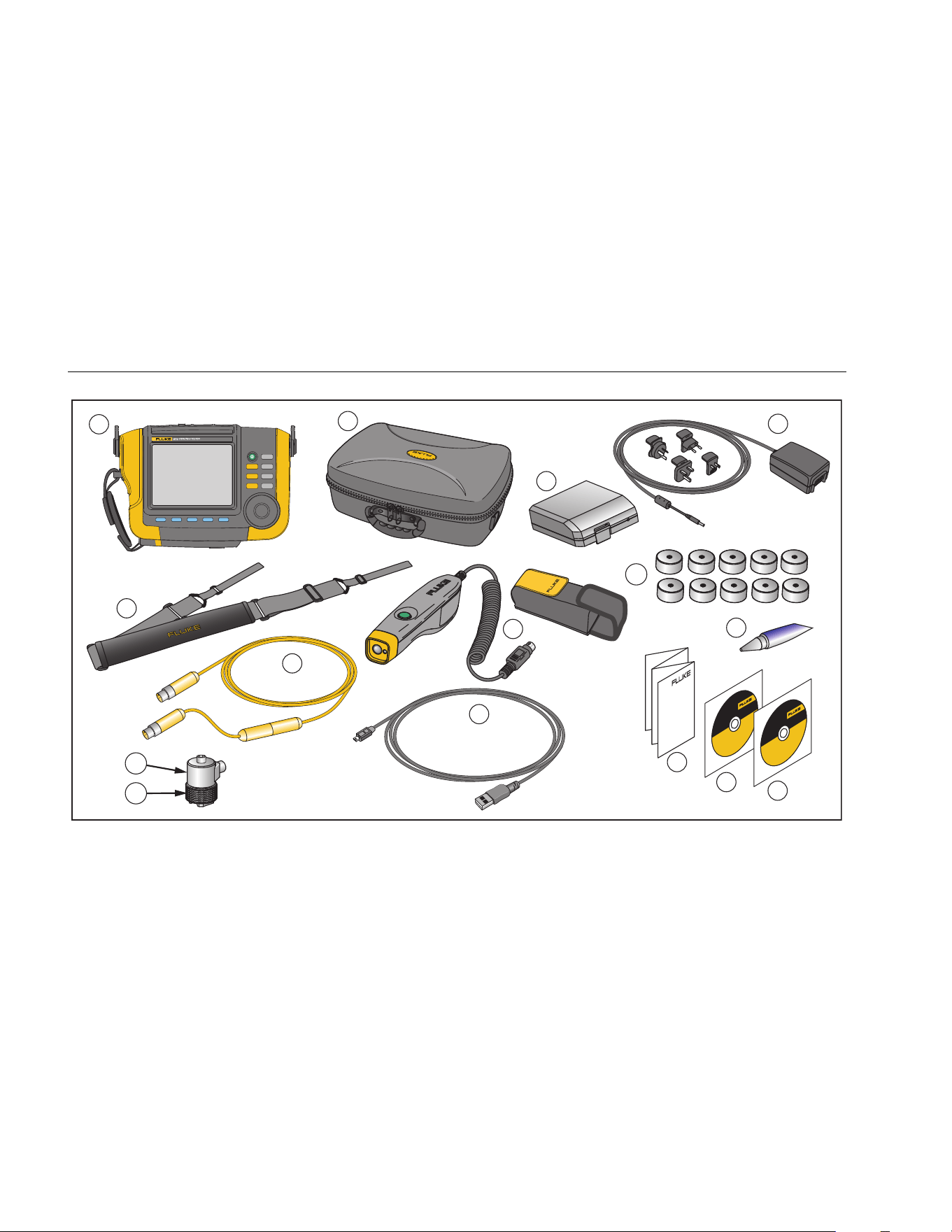
Carefully unpack and inspect all the items in Figure 1-1.
The items that follow are included in your purchase of the
Tester:
Vibration Tester
Storage Case
Smart Battery Pack
Smart Battery Pack Charger and Adapters
Shoulder Strap
Tachometer and Pouch
Sensor
Sensor Magnet Mount
Sensor Quick Disconnect Cable
Sensor Mounting Pads (10-pack)
Adhesive
Mini USB to USB Cable
Quick Reference Guide
User Documentation / Viewer Software CD-ROM
Training DVD
1.888.610.7664 sales@GlobalTestSupply.com
Fluke-Direct.com
810
Users Manual
1-8
F1 F2 F3 F4 F5
SAVE
MEMORY
INFO
INSTRUMENT
SETUP
SETUP
MEASURE
DIAGNOSE
ENTER
10
12
9
4
3
5
6
2
1
14
15
13
11
7
8
gbk10.eps
Figure 1-1. Items Included with the Tester
1.888.610.7664 sales@GlobalTestSupply.com
Fluke-Direct.com

Overview
Storage
1
1-9
Storage
When not in use, keep the Tester in the protective
storage case. The case has sufficient space for the
Tester and all accessories.
Battery
The Tester operates on an internal rechargeable
Lithium-ion battery. After you unpack and inspect the
Tester, fully charge the battery before the first use.
Afterwards, charge the battery when the battery icon on
the screen indicates that power is low. To charge the
battery with the battery in place on the Tester:
1. Connect the ac adapter to the ac input socket of the
battery.
2. Connect the adapter to a power source.
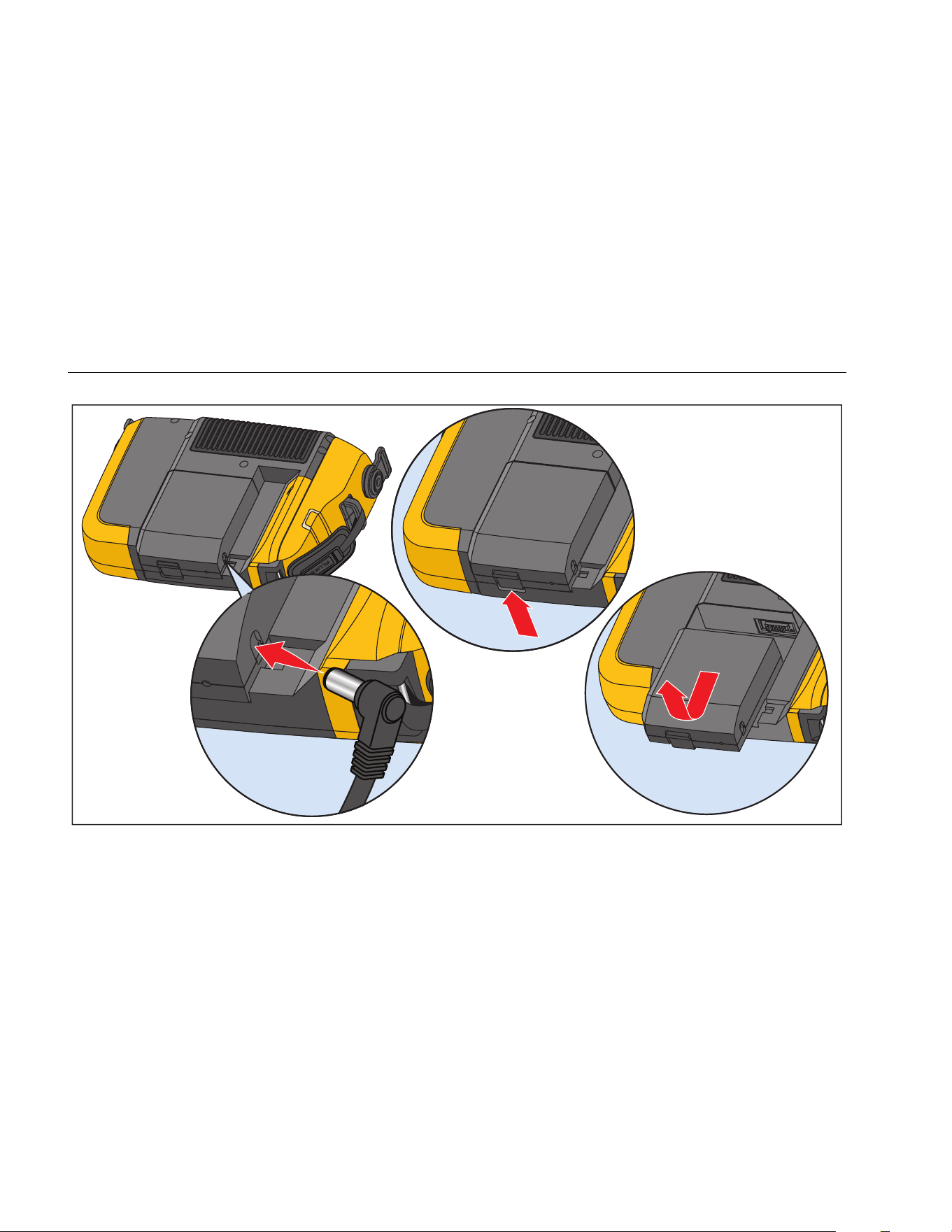
Or, to charge the battery outside the Tester:
1. Remove the battery from the Tester, see Figure 1-2.
2. Connect the ac adapter to the ac input socket of the
battery.
3. Connect the adapter to a power source.
Note
Three hours are necessary for a full battery
charge.
The color of the battery status LED shows:
Red - battery is connected to the power source and
charging.
Green - battery is connected to the power source and is
fully charged.
Caution
To prevent damage to the Tester:
• Use only the ac adapter that is included
with the Tester.
• Make sure that the external power
source is correctly rated for the Tester.
• Do not leave batteries unused for
extended periods of time, either in the
product or in storage.
• When a battery has not been used for six
months, check the charge status and
charge or dispose of the battery as
appropriate.
1.888.610.7664 sales@GlobalTestSupply.com
Fluke-Direct.com
810
Users Manual
1-10
gbk03.eps
Figure 1-2. How to Charge the Battery
1.888.610.7664 sales@GlobalTestSupply.com
Fluke-Direct.com

Overview
Accessories
1
1-11
Accessories
Table 1-2 lists the accessories that are available and sold separately for the Tester.
Table 1-2. Accessories
Model Description Part Number
810T Tachometer 3530819
810S Sensor 3530828
810QDC Quick Disconnect Cable 3530837
SBP810 Smart Battery Pack 3530843
810SMM Sensor Magnet Mount 3530862
810SMP Sensor Mounting Pads 3530855
Note
The maximum cable run is 20 ft (6 m). Do not combine cables to exceed the maximum cable run or you may get
unexpected results.
1.888.610.7664 sales@GlobalTestSupply.com
Fluke-Direct.com

2-1
Chapter 2
Specifications
Title Page
Vibration Tester Specifications ....................................................................................... 2-3
Diagnostic Specifications ........................................................................................... 2-3
Electrical Specifications ............................................................................................. 2-3
General Specifications ............................................................................................... 2-4
Sensor Specifications ..................................................................................................... 2-5
Tachometer Specifications ............................................................................................. 2-6
Viewer Software Requirements ...................................................................................... 2-7
1.888.610.7664 sales@GlobalTestSupply.com
Fluke-Direct.com

Specifications
Vibration Tester Specifications 2
2-3
Vibration Tester Specifications
Specifications are subject to change without notice.
Diagnostic Specifications
Standard Fault Detection ...................................... Unbalance, Looseness, Misalignment and Bearing Failures
Analysis for ............................................................ Motors, Fans, Blowers, Belts and Chain Drives, Gearboxes, Couplings, Centrifugal
Pumps, Piston Pumps, Sliding Vane Pumps, Propeller Pumps, Screw Pumps, Rotary
Thread/Gear/Lobe Pumps, Piston Compressors, Centrifugal Compressors, Screw
Compressors, Closed Coupled Machines, Spindles
Motor Rotational Speed Range ............................ 200 RPM to 12,000 RPM
Diagnosis Details .................................................. Fault Severity (Slight, Moderate, Serious, Extreme), Repair Details, Cited Peaks, Spectra
Electrical Specifications
Ranging .................................................................. Automatic
A/D Converter ........................................................ 4 channel, 24 bit
Usable Bandwidth ............................................... 5 Hz to 20 kHz
Digital Signal Processing Functions ................... Automatically-configured anti-alias filter, High-pass filter, Decimation, Overlapping,
Windowing, FFT and Averaging
Sampling Rate ....................................................... 2.56 kHz to 51.2 kHz
Dynamic Range ..................................................... 128 dB
Signal-to-Noise Ratio ............................................ 100 dB
FFT Resolution ...................................................... 800
Spectral Windows ................................................. Hanning
Frequency Units .................................................... Hz, orders, cpm
Amplitude Units ..................................................... in/sec, mm/sec, VdB (US), VdB* (Europe)
Non-Volatile Memory ............................................. SD micro memory card, 4 GB internal
1.888.610.7664 sales@GlobalTestSupply.com
Fluke-Direct.com

810
Users Manual
2-4
General Specifications
Size ......................................................................... 7.30 in × 2.76 in × 10.52 in (18.56 cm x 7.00 cm x 26.72 cm)
Weight (with battery) ............................................ 4.2 lbs (1.9 kg)
Display ................................................................... ¼ VGA, 320 × 240 Color (5.7 inch diagonal) TFT LCD with LED backlight
Input/Output Connections
Triaxial sensor connection .................................. 4 pin M12 Connector
Single axis sensor connection ............................ BNC Connector
Tachometer connection ...................................... Mini DIN 6 pin Connector
PC connection ..................................................... Mini ‘B’ USB (2.0) Connector
Battery
Battery type ......................................................... Lithium-ion, 14.8 V, 2.55 Ah
Battery charging time .......................................... 3 hr
Battery discharge time ........................................ 8 hr (under normal conditions)
AC Adapter
Input voltage ....................................................... 100 Vac to 240 Vac
Input frequency ................................................... 50/60 Hz
Operating System ................................................. WinCE 6.0 Core
Operating Temperature ........................................ 32 °F to 122 °F (0 °C to 50 °C)
Storage Temperature ............................................ -4 °F to 140 °F (-20 °C to 60 °C)
Operating Humidity ............................................... 10 % to 90 % RH (non-condensing)
Altitude ................................................................... 2000 m
Ingress Protection Rating .................................... IP54
Safety ..................................................................... IEC 61010-1, Pollution degree 2
IEC 60825-1, Class 2
IEC 62133, Lithium battery pack
1.888.610.7664 sales@GlobalTestSupply.com
Fluke-Direct.com

Specifications
Sensor Specifications 2
2-5
Electromagnetic Compatibility
International ........................................................ IEC 61326-1: Portable; CISPR 11: Group 1, Class A
Group 1: Equipment has intentionally generated and/or uses conductively-coupled radio frequency energy that is necessary for
the internal function of the equipment itself.
Class A: Equipment is suitable for use in all establishments other than domestic and those directly connected to a low-voltage
power supply network that supplies buildings used for domestic purposes.
FCC ..................................................................... 47 CFR 15 subpart B. This product is considered an exempt device per clause 15.103.
Korea (KCC) ........................................................ Class A Equipment (Industrial Broadcasting & Communication Equipment)
Class A: Equipment meets requirements for industrial electromagnetic wave equipment and the seller or user should take notice of
it. This equipment is intended for use in business environments and not to be used in homes.
Recommended Calibration Interval ..................... 2 years
Sensor Specifications
Sensor Type ........................................................... Accelerometer
Sensitivity, ±5 %, 25 °C ......................................... 100 mV/g
Acceleration Range ............................................... 80 g peak
Amplitude Nonlinearity ......................................... 1 %
Frequency Response
Z, ±3 dB ............................................................... 2 - 7,000 Hz
X, Y, ±3 dB .......................................................... 2 - 5,000 Hz
Power Requirement (IEPE) ................................... 18-30 VDC, 2-10 mA
Bias Output Voltage .............................................. 12 VDC
Grounding .............................................................. Case grounded
Sensing Element Design ...................................... PZT ceramic / shear
1.888.610.7664 sales@GlobalTestSupply.com
Fluke-Direct.com

810
Users Manual
2-6
Case Material ......................................................... 316L stainless steel
Mounting ................................................................ 10-32 capacitive socket head screw, 2-pole rare earth magnet (48 lb pull strength)
Output Connector ................................................. 4-Pin, M12
Mating Connector ................................................. M12 - F4D
Non-Volatile Memory ............................................ TEDS 1451.4 compatible
Vibration Limit ....................................................... 500 g peak
Shock Limit ............................................................ 5000 g peak
Electromagnetic Sensitivity, Equivalent g .......... 100 μg/gauss
Sealing ................................................................... Hermetic
Temperature Range .............................................. -58 °F to 248 °F (-50 °C to 120 °C) ±7 %
Tachometer Specifications
Dimensions ............................................................ 1.125 in x 4.80 in (2.86 cm x 12.19 cm)
Weight .................................................................... 3.4 oz (96 gr) with cable
Power ..................................................................... Powered by Vibration Tester
Detection ................................................................ Laser Diode Class 2
Range ..................................................................... 6.0 to 99,999 RPM
Accuracy
6.0 to 5999.9 RPM .............................................. ±0.01 % and ±1 digit
5999.9 to 99999 RPM ......................................... ±0.05 % and ±1 digit
Resolution ............................................................. 0.1 RPM
Effective Range ..................................................... 0.4 in to 39.27 in (1 cm to 100 cm)
Response Time ..................................................... 1 second (>60 RPM)
Controls ................................................................. Measure on/off transparent button
1.888.610.7664 sales@GlobalTestSupply.com
Fluke-Direct.com

Specifications
Viewer Software Requirements 2
2-7
Interface ................................................................. 6 Pin Mini DIN
Cable Length .......................................................... 19.586 in (50 cm)
Tachometer Accessories
Reflective tape .................................................... 0.59 in × 20.67 in (1.5 cm x 52.5 cm)
Viewer Software Requirements
Minimum Hardware ............................................... 1 GB RAM
Operating System .................................................. Windows XP, Vista, Windows 7, Windows 8.1
1.888.610.7664 sales@GlobalTestSupply.com
Fluke-Direct.com

3-1
Chapter 3
Getting Started
Title Page
Introduction .................................................................................................................... 3-3
Navigation and User Interface ........................................................................................ 3-3
How to Use the Dial ................................................................................................... 3-5
How to Use the Function Softkeys ............................................................................. 3-5
Accessory Connectors ................................................................................................... 3-6
Start the Tester .............................................................................................................. 3-7
Sensor Setup ................................................................................................................. 3-7
Compatible Sensors .................................................................................................. 3-7
How to Connect the Fluke Sensor ............................................................................. 3-8
Sensor Care and Handling ........................................................................................ 3-9
Tachometer Setup .......................................................................................................... 3-9
How to Measure RPM with the Tachometer .............................................................. 3-9
Laser Safety Precautions .......................................................................................... 3-10
How to Access Help ....................................................................................................... 3-11
Instrument Setup ............................................................................................................ 3-11
Self Test .................................................................................................................... 3-11
Settings ..................................................................................................................... 3-12
Clear Memory ............................................................................................................ 3-14
1.888.610.7664 sales@GlobalTestSupply.com
Fluke-Direct.com
Getting Started
Introduction
3
3-3
Introduction
This chapter helps you to understand and become
familiar with the user interface, connections, and
accessories.
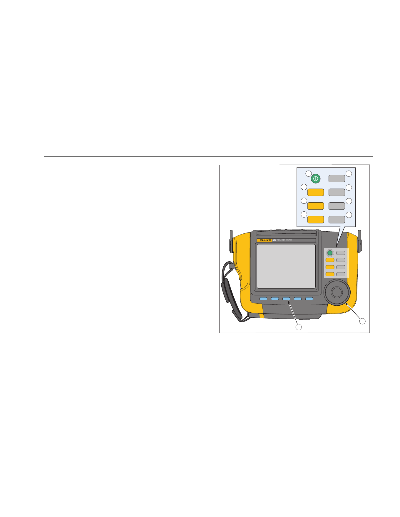
Navigation and User Interface
Figure 3-1 shows the front panel of the Vibration Tester.
Table 3-1 lists the front-panel controls and their functions.
F1 F2 F3 F4 F5
SAVE
MEMORY
INFO
INSTRUMENT
SETUP
SETUP
MEASURE
DIAGNOSE
SAVE
MEMORY
INFO
INSTRUMENT
SETUP
SETUP
MEASURE
DIAGNOSE
1
2
3
4
6
5
7
8
9
10
ENTER
gbk02.eps
Figure 3-1. Front Panel
1.888.610.7664 sales@GlobalTestSupply.com
Fluke-Direct.com

810
Users Manual
3-4
Table 3-1. Front Panel
Item Control Description
Turns the Tester on or off.
Shows the Machine Setup options:
Set up new Machine, Copy Machine
Setup, Change a Machine Setup
Shows the Machine Setups
available for measurement. After the
selection of a Machine Setup,
continue with the measurement
screens.
Shows the completed Machine
Setups with measurements that are
available for diagnosis. After a
measurement, push to see the
diagnosis screen.
Saves the parameters for the Tester
settings and Machine Setups.
Table 3-1. Front Panel (cont.)
Item Control Description
Shows the Machine Setups and
diagnoses in Tester memory.
From the Startup screen, shows the
Help menu. For other screens,
shows Help for the current screen.
Shows the Self Test, Settings, and
Clear Memory functions.
Dial
Turn the Dial to move the cursor
highlight on the screen. Push the
center of the Dial (Enter) to make
the selection.
Softkeys
Softkeys through
make the selections that show on
the screen above each softkey.
1.888.610.7664 sales@GlobalTestSupply.com
Fluke-Direct.com

Getting Started
Accessory Connectors
3
3-5
How to Use the Dial
The Dial has multiple functions. Turn the Dial clockwise or
counterclockwise to move the cursor or highlight. Push
the Dial to make a selection.
How to Use the Function Softkeys
Along the bottom of the display, a row of labels shows the
available functions. Push a softkey, through
, below the display label to start that function.
Table 3-2 lists the navigation softkeys and their function.
Note
When the beeper is on, a short beep sounds for
a valid button push. A long beep sounds for an
invalid button push.
Table 3-2. Navigation Softkey Functions
Softkey Function
Previous Page
/ Next Page
View the previous/next screen.
Enter
Select the highlighted function. Or,
push the Dial to select the same
function.
Back Go to the previous field or screen.
Move Cursor Move the cursor one space to the left.
Delete
Character
Delete a character.
Exit Exit from current display.
Save Save settings in current display.
Done Save keyboard entries.
Also, you can use the front-panel buttons, along the right
side of the Tester, to go directly to a top-level menu.
1.888.610.7664 sales@GlobalTestSupply.com
Fluke-Direct.com
810
Users Manual
3-6
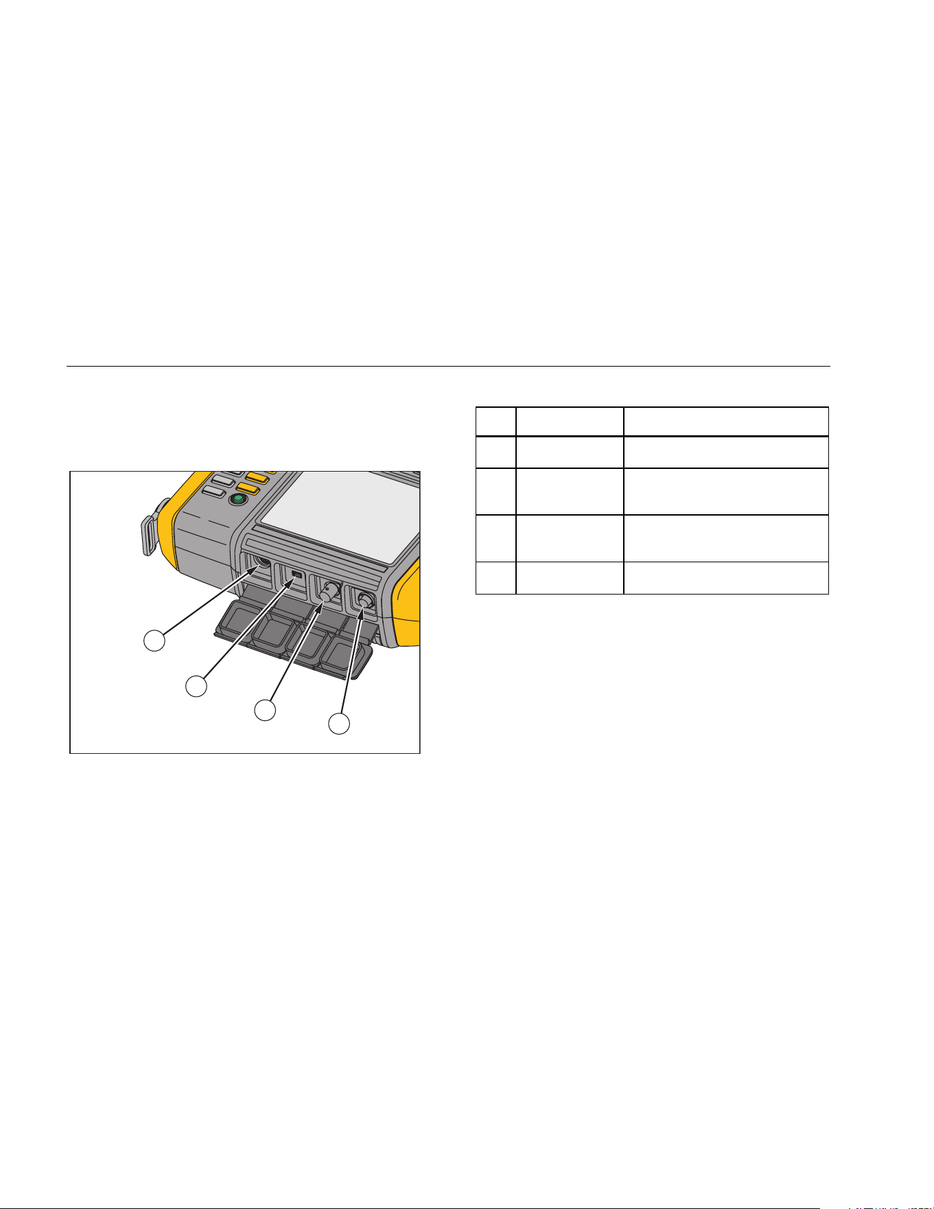
Accessory Connectors
Figure 3-2 shows the connector panel of the Tester.
Table 3-3 is a list of descriptions for each connector on
the Tester.
1
2
3
4
gbk01.eps
Figure 3-2. Accessory Connectors
Table 3-3. Accessory Connectors
Item Connector Description
Tachometer Connects the Tachometer
USB
Connects the Tester to the PC
using a USB cable
Sensor
Optional connector for single
axis Sensor
Sensor Connects the triaxial Sensor
1.888.610.7664 sales@GlobalTestSupply.com
Fluke-Direct.com

Getting Started
Start the Tester
3
3-7
Start the Tester
Note
Before using the Tester for the first time, charge
the battery for at least three hours. For charging
procedure, see Battery.
Before using the Tester, make sure that there is
sufficient battery charge and free memory.
Push to turn on the Tester. At power up, the Tester
displays the remaining memory and the battery status.
The battery status icon and the set date and time
appear at the top of the display.
Push and hold two seconds to turn off the Tester.
Note
The first time you turn the Tester on, it displays
the Settings screen. It is important to enter the
correct information into the setup fields before
you start a test, especially the power line
frequency. For more information, see Instrument
Setup section.
Sensor Setup
The Tester includes a triaxial Sensor with TEDS
technology (Transducer Electronic Data Sheets). With
this technology, your Tester can identify and
automatically read the Sensor configuration. This
technology provides:
• Improved results from detailed calibration information
• Reduced configuration time without manual data
entry
• Sensor calibration tracking with the last calibration
date stored electronically
Compatible Sensors
It is highly recommended to use a Fluke Triaxial Sensor
with the Tester. Using a Sensor other than a Fluke
Triaxial Sensor will result in misleading diagnoses. The
Tester is compatible with single axis Sensors.
Caution
Non-Fluke triaxial Sensors are not
compatible with the Tester.
1.888.610.7664 sales@GlobalTestSupply.com
Fluke-Direct.com
810
Users Manual
3-8
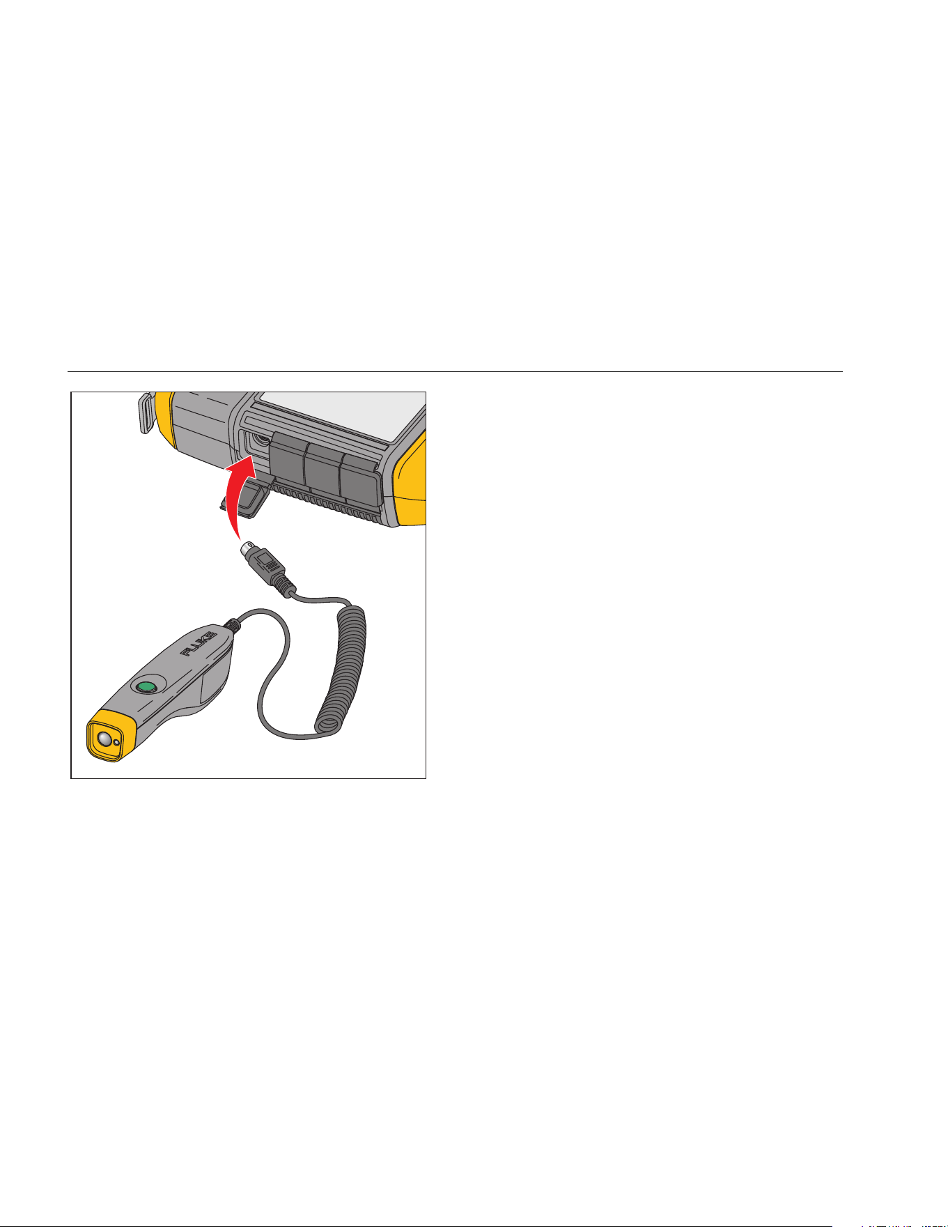
How to Connect the Fluke Sensor
To connect and set up a triaxial Sensor:
1. Attach the cable to the Sensor and tighten the
threaded cable sleeve. See Figure 3-3.
2. Connect the cable to the Tester and tighten the
threaded cable sleeve.
gbk07.eps
Figure 3-3. Sensor Setup and Connection
1.888.610.7664 sales@GlobalTestSupply.com
Fluke-Direct.com

Getting Started
Tachometer Setup
3
3-9
Sensor Care and Handling
Caution
• To prevent damage to the piezoelectric
element inside the Sensor, do not drop.
A faulty Sensor significantly affects the
diagnostic quality.
• Do not pull or force the cable while
attaching or removing the Sensor.
• Allow the Sensor 10 seconds to warm-up
before data collection.
• Make sure that all cables are free from
any rotating parts of the machine.
• Always disconnect the Sensor cable
from the Tester when not in use.
• Always place the Sensor in the softcase
pouch when not in use.
Tachometer Setup
During the Machine Setup procedure, you have to enter
the speed/RPM (revolutions/minute) of the rotating
machine under test. If the RPM is unknown, you can use
the non-contact type laser Tachometer to measure the
RPM.
Note
Fluke recommends the use of a Tachometer for
variable-frequency drives (VFD) to determine the
running speed under varying load conditions.
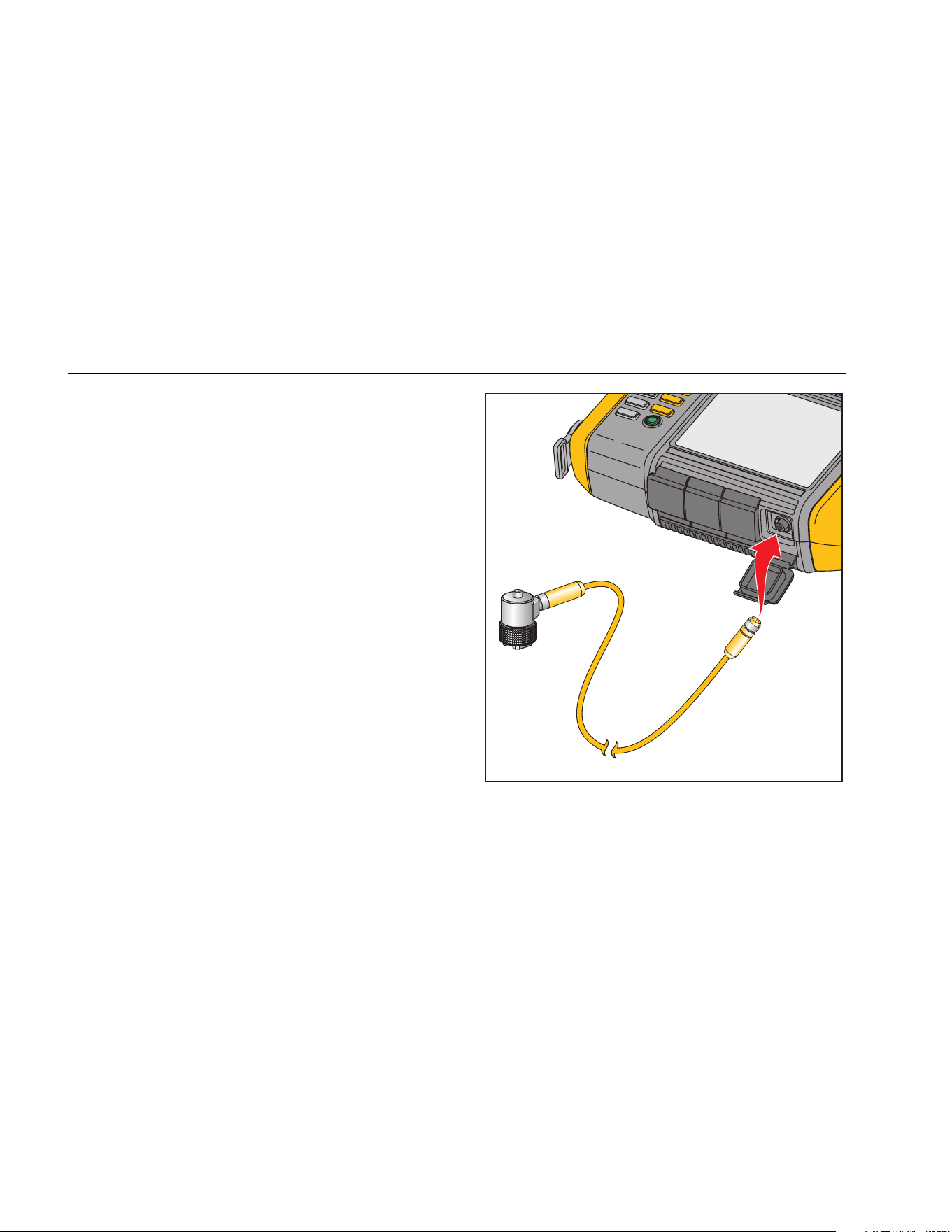
How to Measure RPM with the Tachometer
To make a Tachometer measurement:
1. Attach the Tachometer to the 6-pin DIN connector on
the Tester. See Figure 3-4.
Warning
To avoid injury when attaching reflective
tape to the machine, stop the rotating
machine. Attach a piece of reflective tape
onto the shaft or other rotating part of the
machine. Restart the machine and wait until
it reaches its normal operating conditions.
2. Aim the laser beam towards the attached reflective
tape.
3. Hold the Tachometer firmly and steady.
1.888.610.7664 sales@GlobalTestSupply.com
Fluke-Direct.com
810
Users Manual
3-10
gbk06.eps
Figure 3-4. Tachometer Setup and Connection
4. When the RPM entry screen appears on the display,
the power button on the Tachometer lights to indicate
that the Tester is ready for RPM measurement.
5. Push and hold the trigger button of the Tachometer
to start measuring.
6. After the beep, when the final measured value shows
in green on the Tester, release the trigger button.
The Tester automatically turns off the Tachometer.
Laser Safety Precautions
Warning
• The Tachometer contains a Class 2 laser
pointer.
• To avoid eye damage, do not point laser
directly at eye or indirectly off reflective
surfaces.
• Use, other than those specified here,
may result in hazardous laser radiation
exposure.
• Do not use Tachometer in a manner not
specified in this document or the
protection provided by the equipment
may be impaired.
• Do not aim the laser beam at people or
animals.
1.888.610.7664 sales@GlobalTestSupply.com
Fluke-Direct.com

Getting Started
How to Access Help
3
3-11
Caution
• Keep the Tachometer out of the reach of
children.
• Do not open the Tachometer. The
Tachometer has no user serviceable
parts.
• When not in use, always place the
Tachometer in its protective cover.
How to Access Help
The Tester has context sensitive Help. With the Help
feature you can quickly find additional information while
you set up the Tester and make measurements. The Help
content that shows depends on the current task selection.
Push at any time to view specific Help for the
current task. The Help for the Tester includes these
pages:
• Setup FAQ (Frequently Asked Questions)
• Measurement FAQ
• Diagnosis FAQ
• Glossary
• Troubleshooting
Instrument Setup
Push or the Instrument Setup (F3) softkey to
display the setup options:
• Self test
• Settings
• Clear memory
Use the Dial to highlight an option. Push the Dial or Enter
(F3) to select that option.
Self Test
The Self test option tests the internal modules of the
Tester. When you select the Self test option, the Tester
runs a test module and then displays the self test results
as pass or fail.
Push the Done softkey to go back to Instrument Setup.
1.888.610.7664 sales@GlobalTestSupply.com
Fluke-Direct.com

810
Users Manual
3-12
Settings
To edit the Tester settings in Table 3-4, select the
Settings option. Push Next Page (F2) to move down the
screen and edit the additional settings.
Note
Before you take a measurement, make sure the
power line frequency is set correctly.
Table 3-4. Tester Settings
Option Description
Power line freq
Set the ac power line frequency to 60Hz or 50Hz. The diagnostic quality of a test depends on the
correct selection of the ac power line frequency.
Date format Set the Date format as d/m/y or m/d/y
Date Scroll and set the Day, Month, and Year fields
Time format Set the Time format as 12Hr or 24Hr
Time Scroll and set the Hour, Minute, and AM or PM fields
Beeper Set the Beeper as ON or OFF
Backlight brightness Set the display brightness as High or Low
Power save
Scroll and select to set the delay time for the Sleep Mode. If no key is pushed during the set
time, the Tester goes into the sleep mode to save battery power. Any key push cancels the sleep
mode and resumes normal operation.
1.888.610.7664 sales@GlobalTestSupply.com
Fluke-Direct.com

Getting Started
Instrument Setup
3
3-13
Table 3-4. Tester Settings (cont.)
Option Description
Backlight duration
Scroll and select to set the delay time for the display backlight. If no key is pushed during the set
time, the backlight turns off to save battery power. The backlight turns on when any key is
pushed.
Time waveform
capture
Scroll and select the number of measurements where the time waveform is to be captured. The
Tester captures and stores the time waveform data for the selected number of measurements.
Note
Capture and review of time waveform data is useful in advanced vibration analysis, but
keep in mind that data capture uses a significant amount of memory. Captured time
waveforms can only be viewed in the Viewer Software, not in the Tester.
Units
Scroll and select a unit of measurement as US or metric. Also select the units for the vibration
amplitude. VdB and in/sec for US. VdB* indicates VdB Europe and mm/sec for Metric.
Language Scroll and select a language.
Overall Vibration Unit
Scroll and select a unit of measurement as US or metric. Units are g, m/s2, in/s, mm/s, mils, um.
Also select calculated displacement.
1.888.610.7664 sales@GlobalTestSupply.com
Fluke-Direct.com

810
Users Manual
3-14
Clear Memory
Select the Clear Memory option on the Instrument Setup
screen to erase all measurement and diagnosis data. The
Tester prompts you to clear the memory.
If you select Yes, another confirmation message displays:
Select Yes to clear the memory. This action erases all
stored measurement and diagnosis data.
1.888.610.7664 sales@GlobalTestSupply.com
Fluke-Direct.com

4-1
Chapter 4
Operation
Title Page
Start the Tester .............................................................................................................. 4-3
Create a New Machine Setup ........................................................................................ 4-3
Machine Setup ............................................................................................................... 4-4
Motor Input (Driver) Information................................................................................. 4-5
RPM Entry ................................................................................................................. 4-7
Coupling Information ................................................................................................. 4-7
Transmission with Closed Coupling ...................................................................... 4-8
Transmission without Closed Coupling ................................................................. 4-9
Driven Component ..................................................................................................... 4-10
Pump .................................................................................................................... 4-10
Fan ....................................................................................................................... 4-11
Compressor .......................................................................................................... 4-12
Blower ................................................................................................................... 4-13
Spindle .................................................................................................................. 4-13
Transmission Component .......................................................................................... 4-13
Gearbox ................................................................................................................ 4-13
Belt Drive .............................................................................................................. 4-16
Copy an Existing Machine Setup ............................................................................... 4-18
Edit the Saved Machine Setup .................................................................................. 4-19
1.888.610.7664 sales@GlobalTestSupply.com
Fluke-Direct.com

810
Users Manual
4-2
Before You Measure ...................................................................................................... 4-20
Select Measurement Locations ................................................................................. 4-20
Total Number of Measurement Locations ................................................................. 4-21
Sensor Orientation .................................................................................................... 4-22
Sensor Mounting ....................................................................................................... 4-23
How to Measure Vibration ............................................................................................. 4-25
How to Diagnose ........................................................................................................... 4-32
Fault Types ............................................................................................................... 4-32
Overall Vibration ....................................................................................................... 4-33
Severity Scale ........................................................................................................... 4-34
Fault Details and Vibration Spectrum ........................................................................ 4-35
How to Access the Memory ........................................................................................... 4-38
View by Machine Setup ............................................................................................ 4-39
View by Measurement Date ...................................................................................... 4-39
View by Last Diagnosis ............................................................................................. 4-40
1.888.610.7664 sales@GlobalTestSupply.com
Fluke-Direct.com
Operation
Start the Tester
4
4-3
Start the Tester
Note
• Before using the Tester for the first time,
charge the battery for at least 3 hours. For
charging procedure, see Battery.
• Before using the Tester, make sure that
there is sufficient battery charge and free
memory.
Push to turn on the Tester. At power up, the Tester
displays:
Note
The first time you turn the Tester on, it displays
the Settings screen. It is important to enter the
correct information into the setup fields before
you start a test, especially the power line
frequency. For more information, see the
Instrument Setup section.
Create a New Machine Setup
Before recording data, create a Machine Setup name for
the machine under test. To create a new Machine Setup
name:
1. Push New Machine (F1) on the startup screen. Or
push . The tester displays the options:
• Set up new machine
• Copy Machine Setup
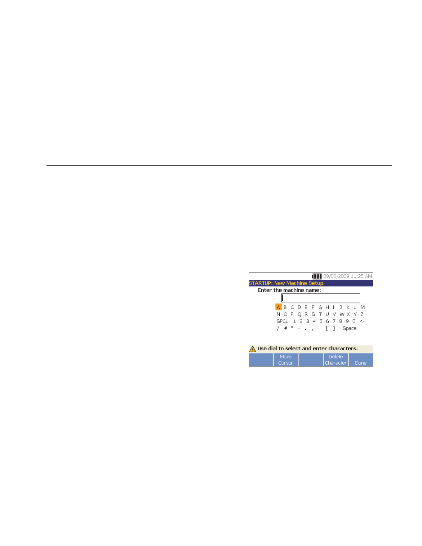
2. Select Set up new machine. An alphanumeric
keyboard appears.
gbk41.bmp
1.888.610.7664 sales@GlobalTestSupply.com
Fluke-Direct.com

810
Users Manual
4-4
3. Use the Dial to highlight characters.
4. Push the Dial to select a character. A maximum of 15
characters is allowable.
5. Push Move Cursor (F2) to move the cursor in the
text box one space to the left.
6. Push Delete Character (F4) to remove the last
character entered in the text box.
7. After you enter the name, push Done (F5). The new
Machine Setup name appears in the name field.
Table 4-1 describes the softkey functions for the New
Machine Setup screen.
Table 4-1. New Machine Setup Functions
Softkey Function
Edit Name Edit the Machine Setup name
Next Go to the first Machine Setup screen
Exit Exit to the Startup screen.
Machine Setup
For the best machine analysis and diagnosis, the Tester
has to understand the layout and components of the
machine. The Machine Setup wizard guides you through
several questions about the profile of the machine. These
machine setup values must be correct for valid diagnostic
results.
Note
All questions in the Machine Setup Wizard are
required to generate a diagnosis unless
otherwise labeled “optional.” Including optional
information will improve the results of the final
machine diagnosis.
Once you create a Machine Name, the Tester starts the
Machine Setup wizard and you enter the parameters of
the machine under test. The Machine Setup wizard
displays the options sequentially based on the input you
give and organizes the options into these categories:
• Motor Input (Driver)
• Coupling and Transmission
• Driven Components
1.888.610.7664 sales@GlobalTestSupply.com
Fluke-Direct.com

Operation
Machine Setup
4
4-5
Note
Push to access the on-board help for any
Machine Setup option.
As you select the options, the Tester displays a
corresponding drivetrain image template at the
top of the display.
gbk115.bmp
The Machine Setup Wizard uses combo boxes. A combo
box is a combination of a drop-down list or list box. You
can choose from the list of existing options. To make a
selection:
1. Push Enter to activate the combo box.
2. Rotate the Dial to highlight different options in the
combo box.
3. Push Enter to confirm the selection. Depending on
the component you select, the options appear for the
details of the component.
Motor Input (Driver) Information
Entering an accurate running speed (RPM) is critical to
receiving a proper diagnosis. An accurate running speed
helps the diagnostic engine in the Tester discern different
fault conditions. The motor nameplate or manual also lists
the running speed.
If an ac motor uses a variable frequency drive (VFD), it
operates under a varying load that influences the
vibration signal. It is important to obtain the correct RPM
using a tachometer. Or, refer to the frequency on the
motor controller label. For consistent diagnoses over
time, it may be necessary to reduce or increase the load
on the motor to match the load from previous
measurements.
Measuring VFDs requires entering RPM at the time of
measurement (instead of relying on RPM values in the
Machine Setup) due to variable loads. To obtain an
accurate RPM value, use the Tachometer provided with
the Tester or obtain the frequency value from the drive
controller itself. To convert the frequency value to RPM,
calculate:
Hz * 60 = RPM
Horsepower (HP) or kilowatt (kW) input is required for the
diagnostic system to identify the number of measurement
locations.
Table 4-2 is a list of the options for the motor input.
1.888.610.7664 sales@GlobalTestSupply.com
Fluke-Direct.com

810
Users Manual
4-6
Table 4-2. Motor Input Options
Selection Option Description
Select motor type
AC
Select the motor type of the machine under test.
DC
AC motor with VFD
Yes
For ac motor type, identify the motor as VFD (variable-frequency
drive) or not.
No
Enter Speed in RPM RPM Entry screen
RPM Entry screen appears. Use the Tachometer to get the RPM. Or,
if you know the RPM, enter the value manually. See RPM Entry.
Enter nominal HP (US)
or
Enter nominal kW (metric)
Numeric keyboard
entry
Push Keyboard to access the numeric keyboard. Enter the HP
(Horsepower) or the kW of the motor.
Motor mounted
Horiz (Horizontal)
Identify the motor mounting as horizontal or vertical. It is important to
enter the motor mounting as it affects Sensor orientation.
Vert (Vertical)
Motor bearing type
Roller
Select the bearing type in the motor. Different bearing types have
distinct vibration signatures.
Journal
Motor is detached from
drivetrain
Yes
Are you testing the motor only. If the motor is detached from the
drivetrain, select Yes.
No
1.888.610.7664 sales@GlobalTestSupply.com
Fluke-Direct.com
Operation
Machine Setup
4
4-7
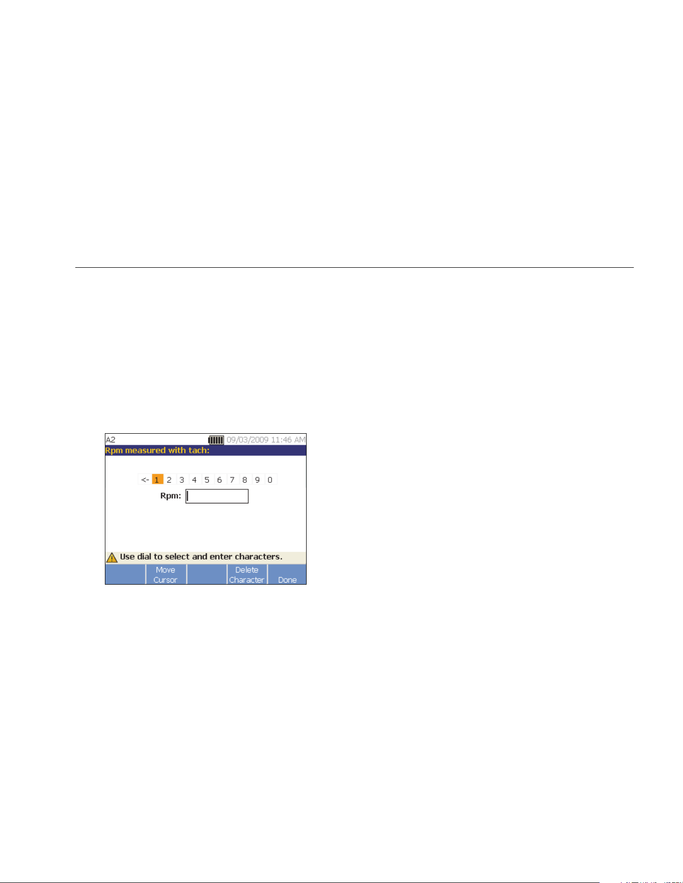
RPM Entry
When an RPM value has to be entered, the RPM entry
screen opens.
Use the Tachometer to measure the RPM. See
Tachometer Setup to set up the Tachometer and
measure the RPM. After you set the RPM value, the
Tester goes back to the Machine Setup wizard.
To manually enter the RPM value:
1. Push Manual Entry (F2). The Tester displays a
numeric keyboard.
gbk43.bmp
2. To select a character, use the Dial to highlight the
value. Or, use Move Cursor (F2) to highlight the
value.
3. Push the Dial to select the value.
4. To delete a character, use Delete Character (F4).
5. Push Done (F5) to go back to the Machine Setup
wizard.
Coupling Information
If the machine consists of a driven component coupled
with a motor, select No to the previous option. Options for
the closed coupled machine appear based on the
selection you make.
1.888.610.7664 sales@GlobalTestSupply.com
Fluke-Direct.com

810
Users Manual
4-8
Transmission with Closed Coupling
Table 4-3 is a list of the options for a transmission with a
closed coupling.
Table 4-3. Closed Coupling Transmission Options
Selection Option Action Option Action Description
Motor
directly
bolted to:
Centrifugal
pump
Scroll and select
the driven
component that
connects to the
motor (driver)
Number of vanes
(optional)
Numeric
keyboard
entry
This is optional information.
Push Keyboard to access
the numeric keyboard. Enter
the appropriate number for
the option.
Gear pump
Number of gear or
screw teeth (optional)
Fan
Number of blades
(optional)
Cntfgl Comp
(Centrifugal
compressor)
Number of
compressor vanes
(optional)
Screw/lobe
pump
Number of teeth/lobes
(optional)
Note: Vanes, gear teeth, screw teeth, pistons and fan blades generate distinct vibration signatures. Enter the correct number for proper
diagnosis.
1.888.610.7664 sales@GlobalTestSupply.com
Fluke-Direct.com

Operation
Machine Setup
4
4-9
Transmission without Closed Coupling
Table 4-4 is a list of the options for a transmission without
a closed coupling.
Table 4-4. Transmission without Closed Coupling Options
Selection Option Description
Coupling between motor
and next component
Yes
Is there a coupling between motor (driver) and the next component in
the drivetrain? Select Yes or No accordingly.
No
Next component
Pump
Scroll and select the next component in the drivetrain from the list.
Fan
Compressor
Blower
Spindle
Gearbox
[1]
Belt drive
[1] [2]
Chain drive
[1] [2]
[1] If you select Gearbox, Belt drive, or Chain drive, the options for the details of the transmission drive appear. See Transmission
Component for related options.
[2]
These selections are unavailable if there is a flexible coupling between the motor and the next component.
1.888.610.7664 sales@GlobalTestSupply.com
Fluke-Direct.com

810
Users Manual
4-10
Driven Component
Depending on the component selection, the options for
the details of the driven component appear.
Pump
Table 4-5 is a list of the pump options.
Table 4-5. Pump Options for Driven Components
Selection Option Action Option Action Description
Bearing
type
Roller --- --- ---
Select the bearing type in the
pump.
Journal --- --- ---
Pump type
Centrifugal
Scroll and
select the
pump type
Impeller is
supported by
Two bearings
Scroll and identify the
impeller support.
Overhung
Number of vanes
(optional)
Input value between 2
and 20 with keyboard.
This is optional information.
Push Keyboard to access
the numeric keyboard. Enter
the number for the option.
Propeller
Number of vanes
(optional)
Input value between 2
and 20 with keyboard.
Sliding
vanes
Number of vanes
(optional)
Input value between 2
and 20 with keyboard.
Screw/lobe
Number of
teeth/lobes (optional)
Select 2 through 12
This is optional information.
Scroll and select the number.
Piston
Number of pistons
(optional)
Select 2 through 13
1.888.610.7664 sales@GlobalTestSupply.com
Fluke-Direct.com

Operation
Machine Setup
4
4-11
Fan
Table 4-6 is a list of the fan options.
Table 4-6. Fan Options for Driven Components
Option Selection Description
Driven component
bearing type
Roller
Select the bearing type in the fan.
Journal
Fan is supported by
Two bearings
Scroll to identify the fan support.
Overhung
Number of fan blades
(optional)
Numeric keyboard entry
This is optional information. Push Keyboard to access the
numeric keyboard. Enter the number of fan blades.
1.888.610.7664 sales@GlobalTestSupply.com
Fluke-Direct.com

810
Users Manual
4-12
Compressor
Table 4-7 is a list of the compressor options. Different
setup options are available based on the compressor
selection.
Table 4-7. Compressor Options for Driven Components
Selection Option Action Option Action Description
Driven
component
bearing type
Roller --- --- ---
Select the bearing type in the compressor.
Journal --- --- ---
Compressor
type
Centrifugal
Scroll and
select the
compressor
type
Number of
vanes
(optional)
Select 9
through 50
Scroll and select the number of vanes in
the compressor.
Screw
Number of
screw teeth
or threads
(optional)
Select 2
through 8
Scroll and select the number of screw
teeth or threads of the compressor.
Piston
Number of
pistons
(optional)
Select 2
through 12
Scroll and select the number of pistons.
1.888.610.7664 sales@GlobalTestSupply.com
Fluke-Direct.com

Operation
Machine Setup
4
4-13
Blower
Table 4-8 is a list of the blower options.
Table 4-8. Blower Options for Driven Components
Option Selection Description
Driven component bearing
type
Roller
Select the bearing type in the blower.
Journal
Number of blower lobes
Select 2 through 12
(optional)
Scroll and select the number of blower lobes.
Spindle
Only single or simple shafts can be analyzed with the
Tester.
Transmission Component
If you select the component as Gearbox, Belt drive, or
Chain drive, the Setup Wizard shows the options for the
transmission component.
Gearbox
To diagnose gearbox faults properly, it is important to
characterize the gear ratios used. The Tester accepts any
of three possible methods: shaft speeds, gear tooth
counts, or gear ratios.
If selecting the shaft speed method for single speed
changers, it is critical to use the same method (manual or
tachometer) on both input and output shafts.
Table 4-9 is a list of the gearbox options. Depending on
the known components, more options appear for the
details.
1.888.610.7664 sales@GlobalTestSupply.com
Fluke-Direct.com

810
Users Manual
4-14
Table 4-9. Gearbox Options for the Transmission
Selection Option Action Option Description
Gearbox
bearing type
Roller
Select the gearbox
bearing type
---
Journal
Number of
speed
changes
1
Scroll and select
the number of
speed changes.
2
3
What is
known?
Shaft speeds
Depending on the
known information,
scroll and select
that option.
Numeric
keyboard entry
Push Keyboard to access the numeric keyboard.
Enter the shaft speeds in their respective fields.
Gear ratios
Push Keyboard to access the numeric keyboard.
Enter the gear ratios in their respective fields.
Gear tooth
count
Push Keyboard to access the numeric keyboard.
Enter the number of gear teeth in their respective
fields.
1.888.610.7664 sales@GlobalTestSupply.com
Fluke-Direct.com

Operation
Machine Setup
4
4-15
Next, the options for the Driven components show on the
Tester screen. See Table 4-10.
Table 4-10. Driven Component Options
Option Selection Description
Is there a flexible coupling between
gearbox and next component:
Yes
Configure the setup with or without a coupling between the
gearbox and the coupling.
No
Next component that gearbox is
attached to:
Pump
Scroll and select the next component in the drivetrain from
the list. See Driven Component for the options.
Fan
Compressor
Blower
Spindle
Belt drive
[1]
Chain drive
[1]
[1] These selections are unavailable if there is a flexible coupling between the gearbox and the next component.
1.888.610.7664 sales@GlobalTestSupply.com
Fluke-Direct.com

810
Users Manual
4-16
Belt Drive
Obtaining the RPM value using the laser tachometer is
the preferred method for determining running speed.
However, the output RPM value can be calculated using
simple arithmetic.
For simple reduction two-pulley (sheave) systems, use
the formula that follows to solve for the RPM of the driven
pulley:
Diameter, driver pulley (sheave)
Diameter, driven pulley (sheave) RPM, driver pulley (sheave)
RPM, driven pulley (sheave)
=
Table 4-11 is a list of the options for the belt drive
components.
Table 4-11. Drive Options for the Transmission
Selection Option Description Action Next Component Action
Belt Drive
Input shaft speed
RPM entry screen
appears
Use the
Tachometer to set
the RPM.
Or, you can enter
the speed with the
numeric keyboard.
Pump
Scroll and select
the next
component in the
drivetrain from the
list. See Driven
Component for
available options.
Output shaft speed Fan
Rotation speed
(optional)
Compressor
Chain Drive
Input shaft speed Blower
Output shaft speed Spindle
Tooth count (optional)
1.888.610.7664 sales@GlobalTestSupply.com
Fluke-Direct.com

Operation
Machine Setup
4
4-17
After you enter all the machine information, the Change
Machine Name screen appears. Table 4-12 is a list of the
softkey functions for the Change Machine Name screen.
Table 4-12. Change Machine Name
Softkey Function
Previous Page Go back to the previous screen.
Review Summary
Go to the first Machine Setup
screen to review the selections and
inputs made with the Machine
Setup Wizard.
Done Save the Machine Setup.
Edit Name
Displays the alphanumeric
keyboard to edit the machine
name.
Exit Exit to the Startup screen.
When you save the Machine Setup, the Tester shows the
Saved Machine Setup screen to indicate the setup was
saved. Table 4-13 is a list of the softkey functions for the
Saved Machine Setup screen.
Table 4-13. Saved Machine Setup Functions
Softkey Function
New Setup
Displays Set up new machine, Copy
Machine Setup, and Change a Machine
Setup options.
Measure
Go to the Measurement screen to take a
measurement from a certain location.
Exit Exit to the Startup screen.
1.888.610.7664 sales@GlobalTestSupply.com
Fluke-Direct.com

810
Users Manual
4-18
Copy an Existing Machine Setup
When you have multiple machines to test that are
identical to one another, you can create one Machine
Setup and make multiple copies with a unique Machine
Setup name.
1. Push to view the New Machine Setup screen
options:
• Set up new machine
• Copy Machine Setup
• Change a machine setup
Or, push New Machine (F1) in the Startup screen to
view the New Machine Setup screen options.
2. Select Copy Machine Setup. The next screen is a
list of the existing Machine Setups.
3. Use the Dial to scroll through the existing Machine
Setups.
4. Push Copy (F3). The alphanumeric keyboard
appears.
5. Enter the new machine name and push Done (F5).
The new name appears on the screen.
6. Push Next (F4) to copy the Machine Setup.
The Tester shows the Copy Machine Setup screen.
Table 4-14 is a list of the softkey functions for the
Copy Machine Setup screen.
Table 4-14. Copy Machine Setup Functions
Softkey Function
Review
Setup
Review the existing Machine Setup
screen-by-screen and edit the settings.
Measure
Go to the Measurement screen to take a
measurement.
Exit Exit to the Startup screen.
1.888.610.7664 sales@GlobalTestSupply.com
Fluke-Direct.com

Operation
Machine Setup
4
4-19
Edit the Saved Machine Setup
To change a Machine Setup:
1. Push to view the New Machine Setup screen
options:
• Set up new machine
• Copy Machine Setup
• Change a machine setup
2. Select the Change a Machine Setup option. The
screen shows a list of the saved Machine Setups.
3. Or, push Saved Machines in the startup screen to
view the saved Machine Setups.
4. Use the Dial to select a Machine Setup.
5. When the Machine Setup is highlighted, push Edit
Setup (F3). The Machine Setup screen appears and
you can edit the settings.
6. Editing the settings is similar to creating the Machine
Setup for the first time. Refer to the Machine Setup
section for more information about the Machine
Setup settings.
Once you edit the machine settings, the Change
Machine Name screen appears.
Table 4-15 is a list of the softkey functions for the
Change Machine Name screen.
Table 4-15. Change Machine Name Functions
Softkey Function
Previous
Page
Go to the previous screen.
Review
Summary
Go to the Machine Setup screen to
review the selections and inputs made in
Machine Setup wizard.
Done
Save the Machine Setup with new
settings.
Edit Name
Displays alphanumeric keyboard to edit
the machine name.
Exit Exit to the Startup screen.
Note
You can create a Machine Setup and transfer it
to and from the Tester with the Viewer Software.
For more information, see Chapter 5, Viewer
Software.
1.888.610.7664 sales@GlobalTestSupply.com
Fluke-Direct.com

810
Users Manual
4-20
Before You Measure
Sensor orientation is critical to ensure repeatable data
and consistent diagnoses over time. Once you have
mounted the Sensor onto the machine to be tested and
created a Machine Setup, the Tester is ready to measure.
Caution
To prevent damage to the Tester, do not take
a measurement while connected to ac power
source.
Select Measurement Locations
The optimum measurement location is as close to the
machine bearings as possible. A solid metal surface
between the bearing and Sensor is ideal. The solid metal
casting effectively transmits the vibration signals emitted
by bearings. Do not put the Sensor on bearing caps, fan
housings, sheet metal shrouds, non-metallic materials,
and other metal-to-metal joints as they can significantly
distort the vibration signals.
Tips for measurement location:
• For consistent diagnoses over time, it is important to
measure with the same parameters. You must place
the triaxial Sensor at the exact same location on a
machine and with the same orientation.
• Do not take bearing measurements from a
foundation or fabricated base.
• Do not mistake seal locations for a bearing
measurement location on pumps.
• Attach the Sensor to a clean, flat, bare metal surface
if possible. Thick layers of paint, grease, oil, or other
matter reduce both the holding force of the magnet
and the high frequency response of the Sensor.
• Avoid mounting the Sensor on thin surface areas,
such as fan shrouds and cooling fins.
• The position of the cable connection on the Sensor
should be parallel or perpendicular to the drive shaft
whenever possible.
• For close-coupled machines where the motor is
directly bolted to the driven component, take all
measurements from the motor. If motor is <40 hp
(30 kW), take the measurement from the motor’s
driven end. If the motor is >40 hp (30 kW), take the
measurement from both the motor’s driven end and
free end.
Warning
To prevent personal injury, do not allow
Sensor location and mounting to supersede
safety. Always consider the best
combination of locations and mounting
techniques that personal safety will allow.
1.888.610.7664 sales@GlobalTestSupply.com
Fluke-Direct.com
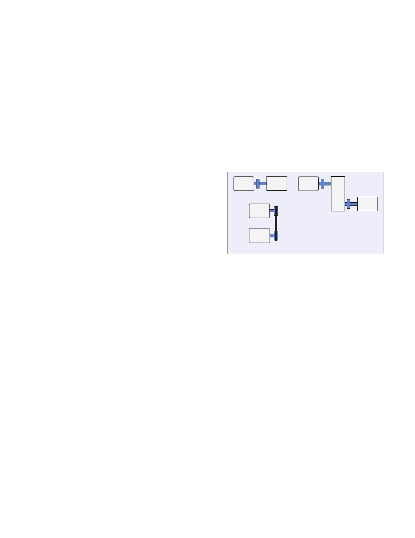
Operation
Before You Measure
4
4-21
Total Number of Measurement Locations
Measurement locations correlate to the bearing locations
and their sequence follows the flow of energy beginning
from the free end of the motor to the end of the drivetrain.
Take measurements in this same order, beginning with
the free end of the motor and working downstream. See
Figure 4-1.
Fluke recommends that you make two measurements for
each component in the drivetrain (unless the bearings are
less than 36 in (1 m) apart). For optimum diagnostic
quality, make each measurement at the bearing location
when possible.
12 34
7
8
12
Motor
Motor Pump
12 34
56
Motor
Gear Pump
Pump
43
gbk09.eps
Figure 4-1. Sensor Location
Note
Start numbering from the motor free end.
Number the bearings with the flow of energy.
1.888.610.7664 sales@GlobalTestSupply.com
Fluke-Direct.com
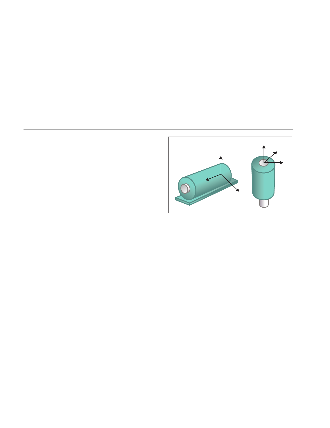
810
Users Manual
4-22
Sensor Orientation
Consistent Sensor orientation is critical to ensure
repeatable data and consistent diagnoses over time. The
Tester uses a triaxial Sensor that combines three
transducers into a single housing. These three
transducers simultaneously measure the vibration data
from three axes or directions:
• Axial (A)
• Radial (R)
• Tangential (T)
The axes are oriented to the drivetrain shaft and vary
depending on the horizontal or vertical orientation of the
drivetrain. See Figure 4-2.
Note
If you define the Sensor orientation incorrectly in
the user interface, the diagnostic engine is
unable to associate the vibration signals with the
correct axes. The result is a false diagnosis from
the Tester.
R
T
R
T
A
A
A = Axial
R = Radial
T = Tangential
gbk08.eps
Figure 4-2. Axes Orientation
The Tester uses the machine driveshaft as the common
reference point. You must set the orientation of the
Sensor cable as either parallel or perpendicular to the
driveshaft.
1.888.610.7664 sales@GlobalTestSupply.com
Fluke-Direct.com
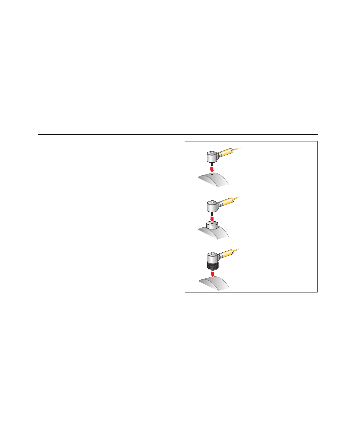
Operation
Before You Measure
4
4-23
Sensor Mounting
The Tester’s diagnoses are largely dependent upon the
quality of vibration signal it receives from the machinery
under test. The method used to mount a Sensor to the
machine directly affects the quality, accuracy, and range
of the signal, see Figure 4-3.
In general, permanent mounts, such as stud or adhesive
mount, yield the best results. These are best for
machines that:
• run at high speeds and frequencies
• have a driving unit that runs at greater than
6000 RPM (for example, vacuum pumps)
• include a speed changer (gearbox) that results in an
output shaft speed of greater than 5x the input shaft
speed
• include an integrated speed changer (for example,
centrifugal compressors)
Permanent mountings promote more consistent data if
tracking machine condition over time. The advantages
and disadvantages of permanent mounts are as follows.
Stud Mount
Adhesive Mount
Magnetic Mount
gbk11.eps
Figure 4-3. Sensor Mounting Options
1.888.610.7664 sales@GlobalTestSupply.com
Fluke-Direct.com

810
Users Manual
4-24
Stud Mounting
Stud mounting is typical for permanently mounted
applications. A hole is tapped into a flat section of the
machinery housing and the Sensor’s stud is screwed into
the tapped hole.
Advantages: Highest frequency response, very
repeatable data over time. Best diagnostic quality.
Disadvantages: Less practical for “walkaround”
troubleshooting due to time needed to screw/unscrew the
Sensor from machinery, often difficult to tap a hole in the
desired measurement location.
Adhesive Mounted Pads
Typically used for permanently mounted applications. A
thin layer of adhesive is applied to the bottom of the
mounting pad and placed on a flat section of the
machinery housing. The Sensor’s stud is screwed into the
hole in the mounting pad.
Advantages: High frequency response approaching that
of a stud mount without having to tap a hole, very
repeatable data over time. Next to a stud mount, best
diagnostic quality.
Disadvantages: Less practical for “walkaround”
troubleshooting due to time needed to screw/unscrew the
Sensor from mounting pad.
The advantages and disadvantages of a temporary mount
are as follows.
Magnetic Mounting
The magnetic mount uses either a 2-pole magnet (for
rounded surfaces) or flat magnet attached to the Sensor.
If you make the measurements at the exact same
location, each time, repeatable data can be collected over
time. Magnet mounts are generally more convenient and
allow faster measurement, but some accuracy is lost.
Advantages: Fastest, most convenient method for
“walkaround” troubleshooting.
Disadvantages: Diagnostic quality is less than that of
stud or adhesive mounts.
Caution
When using a magnetically mounted Sensor,
be careful when attaching it to the test
surface. The magnet is very strong and could
pull the Sensor assembly from your hand
and impact the test surface. An excessive
impact can damage the Sensor. Hold the
Sensor firmly and carefully roll the Sensor
onto the test surface to minimize the
potential for impact.
1.888.610.7664 sales@GlobalTestSupply.com
Fluke-Direct.com
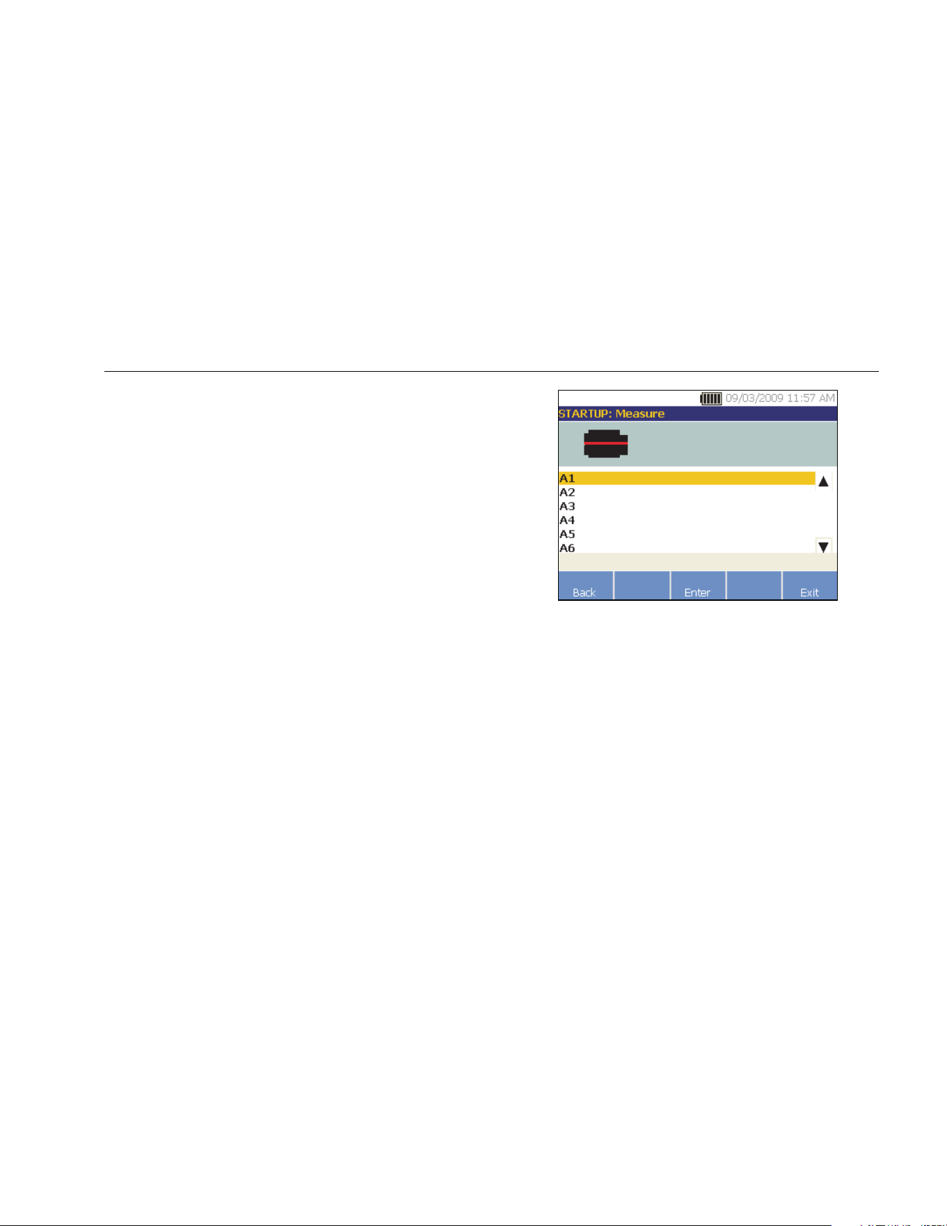
Operation
How to Measure Vibration
4
4-25
How to Measure Vibration
Best practice is to take vibration measurements when the
machine is running in a steady state and at normal
operating temperature. Fluke recommends that you make
two measurements for each component in the drivetrain
(unless the bearings are less than 36 in (1 m) apart). For
optimum diagnostic quality, make each measurement at
the bearing location when possible.
Multiple measurements will improve the diagnostic
quality. You need to test all the components, but not
necessarily all the possible Sensor locations on each
component. Vibration transmits easily through a machine
and it will be picked up from each location.
To measure machine vibration with the Tester:
1. Push . The Measure screen shows the saved
Machine Setups ready for measurement.
2. Rotate the Dial to highlight a Machine Setup and
push the Dial or Enter (F3) to select the saved setup.
gbk51.bmp
The Tester automatically detects and configures the
settings for the Sensor unless the drivetrain includes
a variable frequency drive (VFD) or dc motor. If there
is a VFD or dc motor, you must verify the RPM in the
RPM Entry screen which appears next.
3. To enter the RPM, choose a method:
• Retake the RPM measurement.
• Manually enter the RPM.
• Push Skip to skip the RPM Entry screen.
The Tester configures the settings and detects the
Sensor.
1.888.610.7664 sales@GlobalTestSupply.com
Fluke-Direct.com
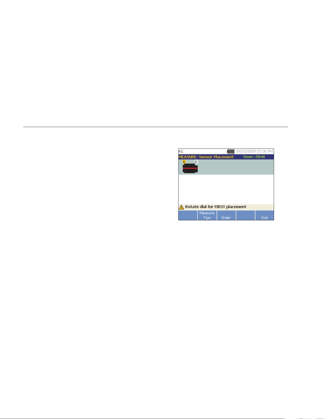
810
Users Manual
4-26
Note
Because the current running speed is so critical
for correct diagnosis, it is a best practice to use
a Tachometer on VFD motor controllers. Or,
refer to the frequency on the motor controller
label before you take a measurement.
If a single axis Sensor is detected, the Tester asks
for the sensitivity of the Sensor.
4. To input the sensitivity value of the Sensor, push
Keyboard (F4) and enter the value.
5. Push Continue.
Once the Sensor is selected, a new screen shows
the options:
• New orientations / locations
• Use last orientations / locations
Note
The first time you take a measurement, draw or
paint a line on the machine to indicate the
Sensor measurement location. Use an arrow to
indicate the Sensor orientation. If you take
measurements at exact same locations and
with exact same Sensor orientations, you can
push Use last orientations/locations. This will
bypass the location and orientation screens and
take you directly to the data collection screen.
6. Select New orientations / locations. The Sensor
Placement screen appears.
gbk56.bmp
7. Rotate the Dial to select the location for the first
Sensor placement. Locations are shown above the
drivetrain image. The time available for taking
measurements is shown in the top right side of the
display.
1.888.610.7664 sales@GlobalTestSupply.com
Fluke-Direct.com
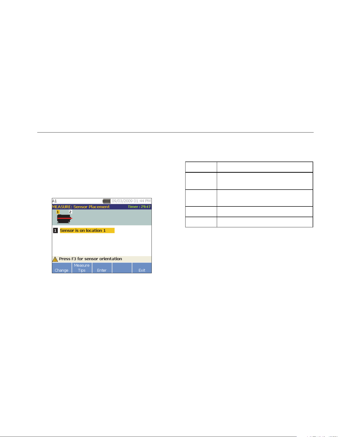
Operation
How to Measure Vibration
4
4-27
Note
The vibration from a drivetrain may change
depending on the load and ambient temperature
of the motor. You must finish a measurement
within 30 minutes. If not, the “Measurement
Timeout” message appears and redirects you to
select the Sensor orientation and location.
8. Push Enter (F3) to select the location. The Tester
shows that the Sensor is located.
gbk57.bmp
Table 4-16 is a list of the softkey functions for the
Sensor Placement screen.
Table 4-16. Sensor Placement Functions
Softkey Function
Change
Go back to the previous screen to change
the Sensor location.
Measure
Tips
Display information and tips for taking
measurements.
Enter Displays the Sensor Orientation screen.
Exit Exit to the Startup screen.
1.888.610.7664 sales@GlobalTestSupply.com
Fluke-Direct.com
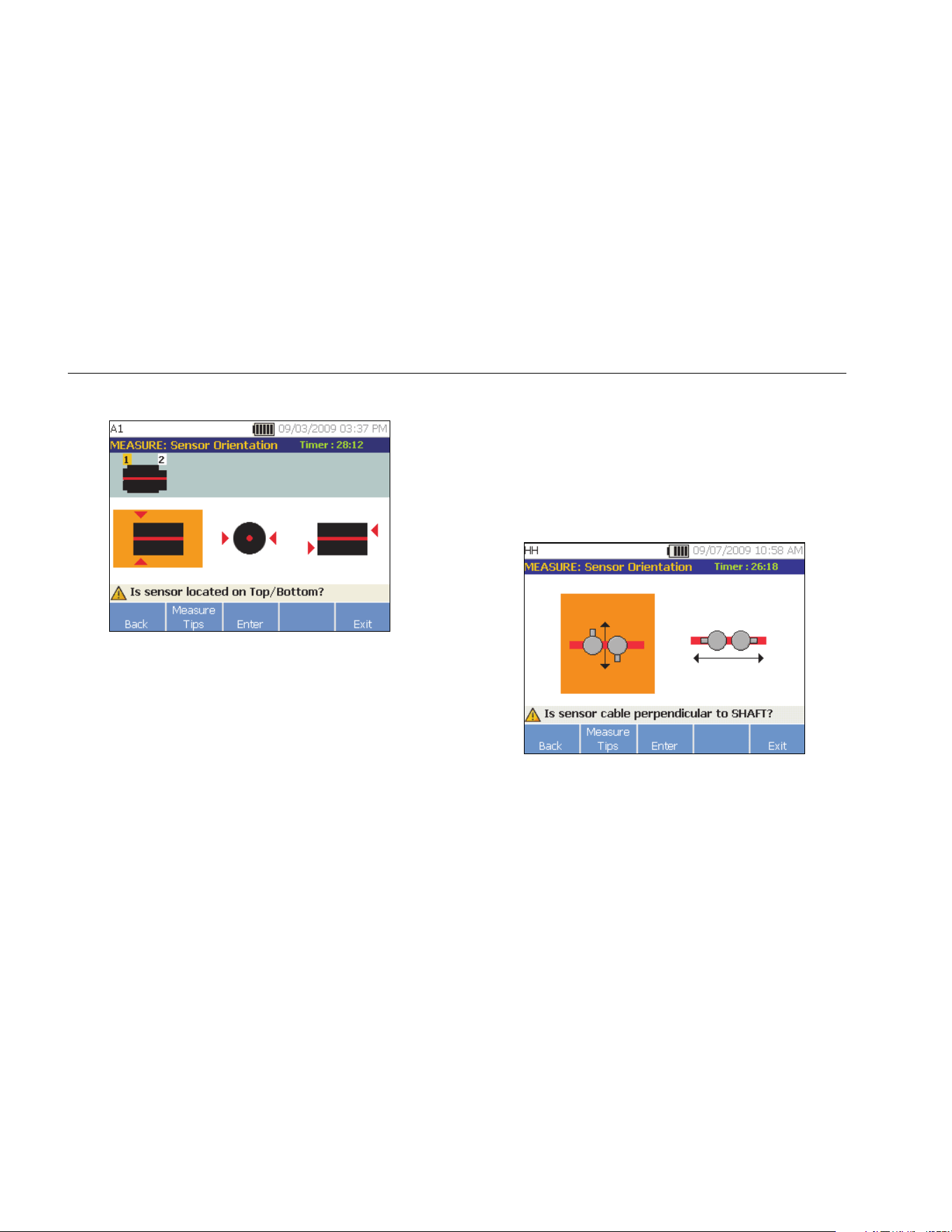
810
Users Manual
4-28
9. Push Enter (F3) to select the Sensor orientation.
gbk58.bmp
10. Use the Dial to select the correct position of the
Sensor the location:
• For horizontal mountings select: Top/Bottom,
Side, or End
• For vertical mountings select: Front/Back, Side,
or End. The first time you make a measurement,
identify the side of the motor that is the front.
Make a mark on the motor to show the front and
the back of the motor for future measurements.
Depending on the Sensor orientation selection,
another screen appears.
The Tester uses the driveshaft (depicted as a thick
red line in the display) as the primary frame of
reference. Orient the Sensor to the driveshaft using
the Sensor cable where it exits from the Sensor,
telling the Tester whether the cable is parallel or
perpendicular to the shaft.
gbk59.bmp
1.888.610.7664 sales@GlobalTestSupply.com
Fluke-Direct.com
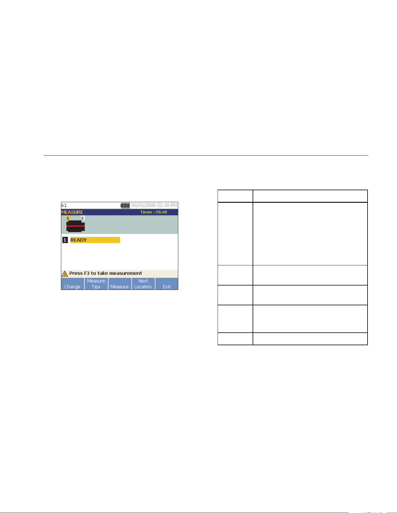
Operation
How to Measure Vibration
4
4-29
11. Use the Dial and select the alignment of the Sensor
cable as it relates to the machine driveshaft. The red
line (or dot) on the screen graphic represents the
driveshaft. After you select the orientation, the
measurement screen appears.
gbk60.bmp
Note
The vibration from a drivetrain may change
depending on the load and ambient temperature
of the motor. You must finish a measurement
within 30 minutes. If not, the “Measurement
Timeout” message appears and redirects you to
select the Sensor orientation and location.
Table 4-17 is a list of softkey functions for the
Measurement Functions screen.
Table 4-17. Measurement Functions
Softkey Function
Change
Displays the options:
• Re-orient Sensor: Sensor
Orientation screen appears. Change
the orientation.
• Relocate Sensor: Sensor
Placement screen appears. Change
the Sensor position.
Measure
Tips
Displays information and tips for taking
measurements.
Measure
Take measurement from the selected
location.
Next
Location
Move to the screen where you can select
the next location to place the Sensor on
the drivetrain.
Exit Exit to the Startup screen.
1.888.610.7664 sales@GlobalTestSupply.com
Fluke-Direct.com
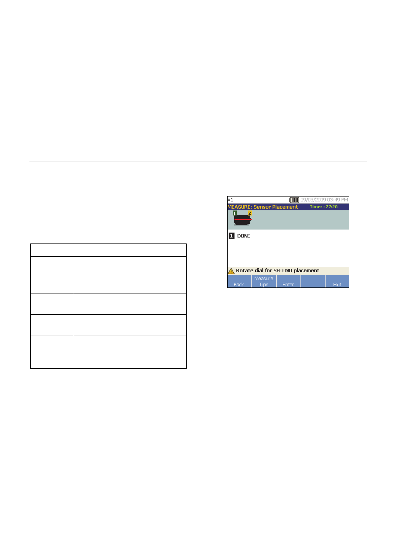
810
Users Manual
4-30
12. Push Measure (F3) to measure from the selected
location. The Tester checks for the Sensor cable
connection. If the connection is good, the Tester
measures the machine under test. The Measurement
Complete screen appears when the measurement is
complete.
Table 4-18 is a list of the softkey functions for the
Measurement Complete screen.
Table 4-18. Measurement Complete Functions
Softkey Function
More…
Displays the options to Re-orient and
Relocate the Sensor and Re-measure.
Push the required softkey to perform
the specific task.
Measure Tips
Displays information and tips for how to
take measurements.
Diagnose
Diagnose the measurements from a
machine.
Next
Location
Move to the next Sensor location on the
drivetrain.
Exit Exit to the Startup screen.
13. When taking measurements at multiple locations,
push Next Location (F4). The Sensor Placement
screen appears for a second placement.
gbk62.bmp
14. Rotate the Dial and select the location for the next
placement.
15. Push Enter (F3) or use the Dial to select Sensor
orientation. The Sensor Orientation screen appears.
1.888.610.7664 sales@GlobalTestSupply.com
Fluke-Direct.com
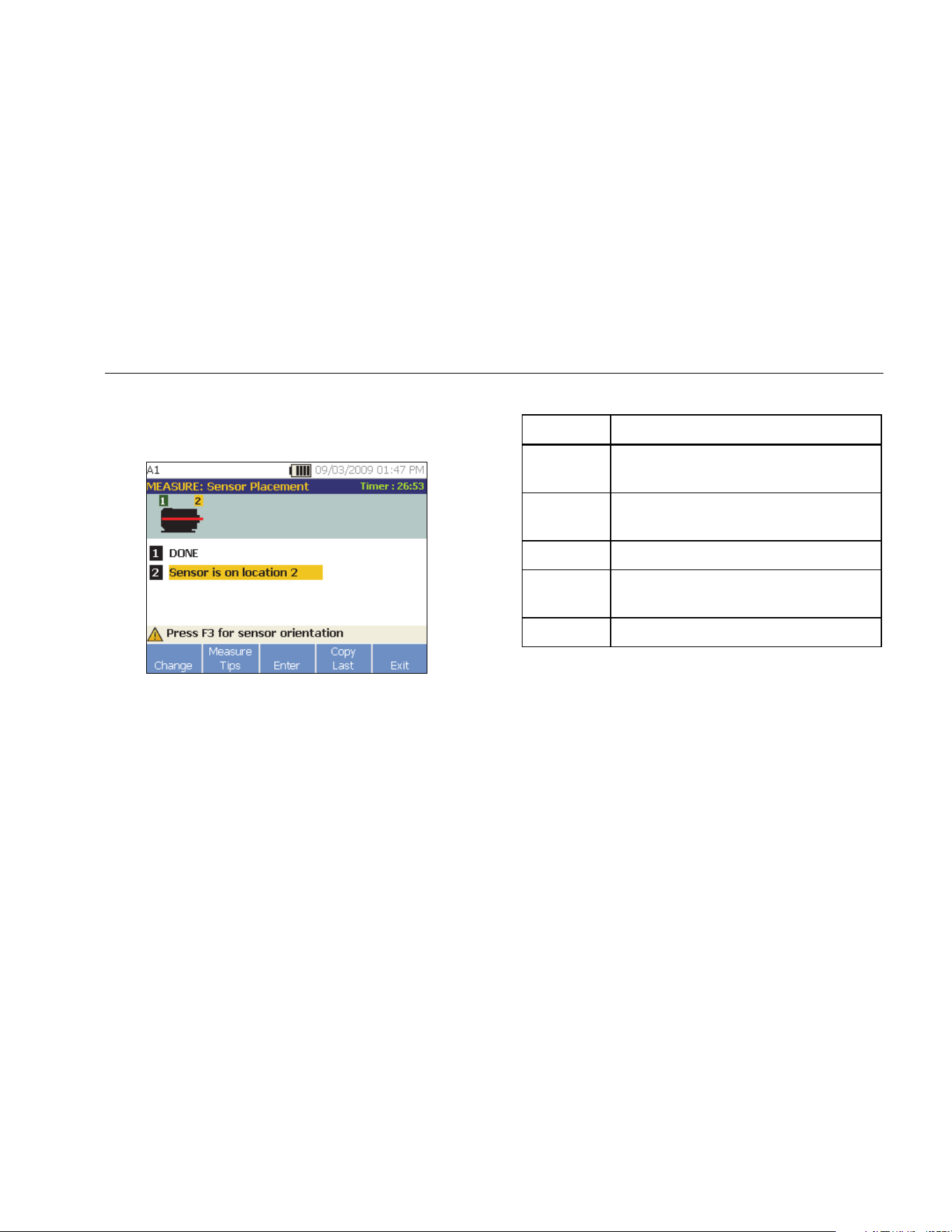
Operation
How to Measure Vibration
4
4-31
16. Select the placement of the Sensor.
17. In the next screen, select the orientation of the
Sensor.
gbk63.bmp
Table 4-19 is a list of the softkey functions for the
Sensor placement.
Table 4-19. Sensor Placement Functions
Softkey Function
Change
Go back to the previous screen to change
the Sensor location.
Measure
Tips
Displays information and tips for taking
measurements.
Enter Displays the Sensor Orientation screen.
Copy Last
Copy the position and orientation of the
last Sensor placement if it is the same.
Exit Exit to the Startup screen.
18. Push to take the measurement.
1.888.610.7664 sales@GlobalTestSupply.com
Fluke-Direct.com
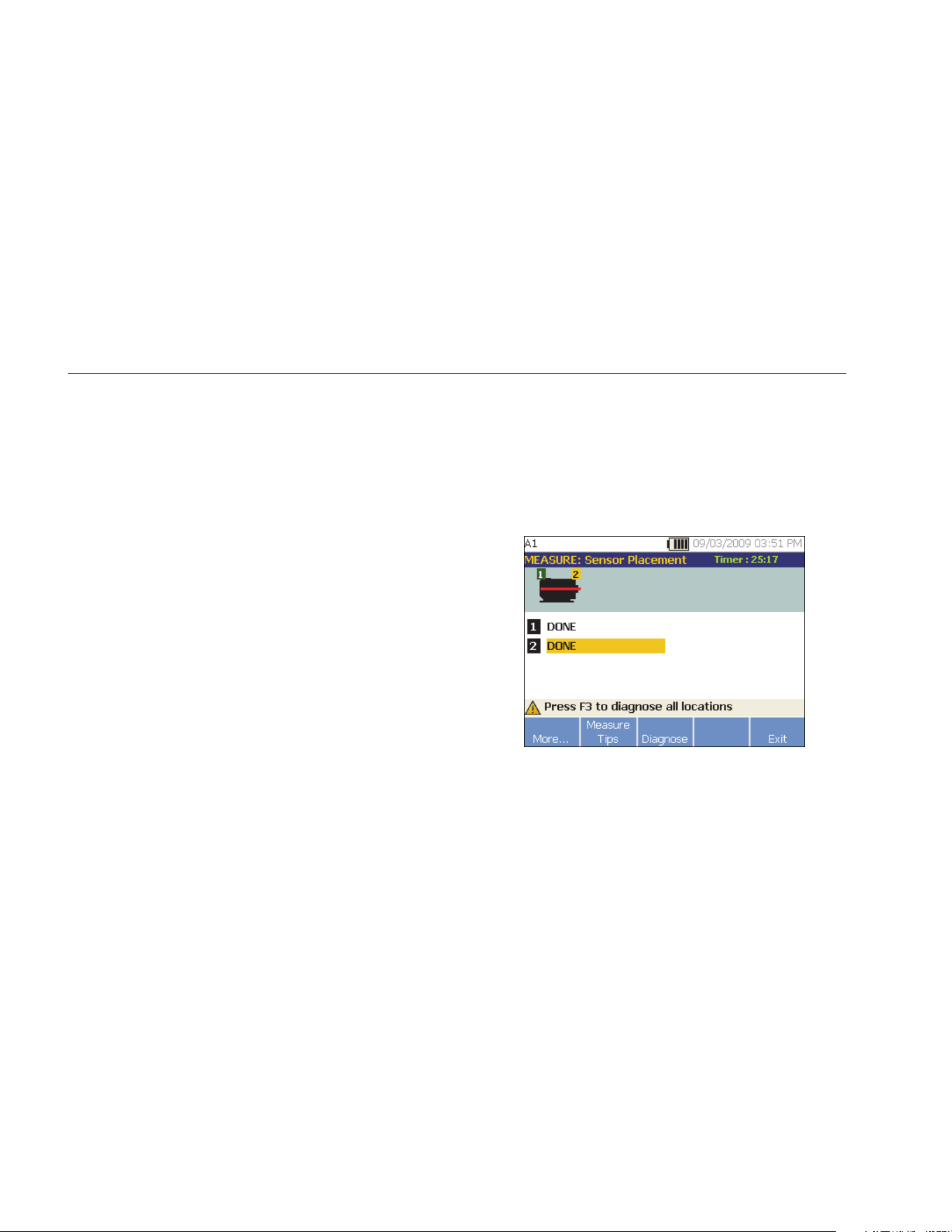
810
Users Manual
4-32
How to Diagnose
Once the Machine Setup is complete and measurement
information is collected, the diagnostic engine analyzes
the data with a set of powerful algorithms. It also identifies
abnormal conditions and pending mechanical failures for
the machine.
Fault Types
The Tester can identify four of the most common
mechanical problems:
• Bearing Failures
• Misalignment
• Unbalance
• Looseness
The diagnostic engine can identify other mechanical
faults (nonstandard faults) in addition to these four basic
faults. However, it cannot provide any details on the type
of the fault, only its severity.
To diagnose a machine after you take a measurement:
1. Take a measurement. Once the measurement is
done, the Tester displays the Measurement
Complete screen and prompts you to diagnose the
measurements.
See Table 4-18 for a list of the softkey functions for
the Measurement Complete screen.
gbk64.bmp
1.888.610.7664 sales@GlobalTestSupply.com
Fluke-Direct.com

Operation
How to Diagnose
4
4-33
2. Push Diagnose (F3). Or, push the Dial to start the
Diagnosis. The Tester analyses the measurement
data and displays the diagnostic results.
gbk265.bmp
Table 4-20 is a list of the softkey functions for the
Diagnosis: Faults screen.
Table 4-20. Diagnosis Faults
Softkey Function
Repair
Details
Displays the prioritized repair
recommendations related to a particular
diagnosis.
History
Displays the previous diagnosis with same
machine.
Details
Displays fault details and cited peaks for
selected fault.
Next Go to the next fault.
Exit Exit to the Startup screen.
Overall Vibration
The Overall Vibration measurement shows in the upper
right of the Diagnosis screen.
1.888.610.7664 sales@GlobalTestSupply.com
Fluke-Direct.com

810
Users Manual
4-34
Severity Scale
The scale is an indication of severity for any particular
fault machine condition.
Slight Moderate Serious Extreme
gbk13.eps
Note
The severity scale should not be associated with
time to failure.
The severity scale is based on the intensity of the
machine fault at the time of measurement. It is not an
indicator of time to machine failure. As conditions change,
the severity may change, even appear to improve (for
example, immediately after lubrication). However, over
time, conditions will worsen with normal machine wear
and tear.
Note
Time to failure will vary depending on the
equipment type, age, machine load,
environmental conditions, and other variables.
Follow these recommended actions for each severity
level to avoid failure. In general, the scale may be
interpreted as:
• Slight No repair action is recommended.
Monitor the machine and retest after
regular machine planned maintenance
to verify maintenance was performed
correctly.
• Moderate (Months, even up to a year) – Repair
action may be needed in the future. A
machine failure is possible, so plan
accordingly. Increase the frequency of
vibration testing on this equipment and
review spare parts availability.
• Serious (Weeks) – Repair action may be
needed before the next planned
downtime. There may be other physical
evidence of the fault in terms of noise
or higher bearing temperatures. Retest
the machine within a short period to
confirm finds. Limit the run time of the
machine, if possible, and determine a
fault progression trend to prevent
additional component failure.
1.888.610.7664 sales@GlobalTestSupply.com
Fluke-Direct.com

Operation
How to Diagnose
4
4-35
• Extreme (Days) – Consider shutting down the
equipment and taking repair action now
to avoid catastrophic failure. There is
likely other physical evidence of the
fault in terms of noise, higher bearing
temperatures or visible movement.
Retest the machine within a short
period to confirm finds.
To monitor the condition and degradation of the machine
over time, upload the diagnostic information to the Viewer
Software and track each fault’s severity. See the Viewer
Software section for more details.
If the diagnosis shows extreme faults but you do not
sense any visual or thermal indication of the fault, revisit
Machine Setup and How to Measure Vibration. Verify that
you have the correct machine information and
measurements. Several factors can result in poor data
collection and inaccurate diagnoses:
• Improper speed input
• Improper machine setup
• Thermal transients
• Improper measurement locations
• Taking measurements from a machine which is
cycling or surging on and off
Fault Details and Vibration Spectrum
The Tester collects data about vibration motion and
compiles this information in the time domain. Then, the
Tester transforms it into a frequency domain (spectra)
graph where the amplitude of the vibration signal is
graphed against the frequency or machine RPM.
Mechanical faults are detected at certain running speeds
or frequencies in the spectra. The algorithms identify, or
“cite” the abnormal vibration amplitude peaks (cited
peaks) at vibration spectra and then diagnose the
mechanical fault and severity.
For machines where the Tester found no faults, the
Details screen shows spectral data but not cited peaks.
1.888.610.7664 sales@GlobalTestSupply.com
Fluke-Direct.com
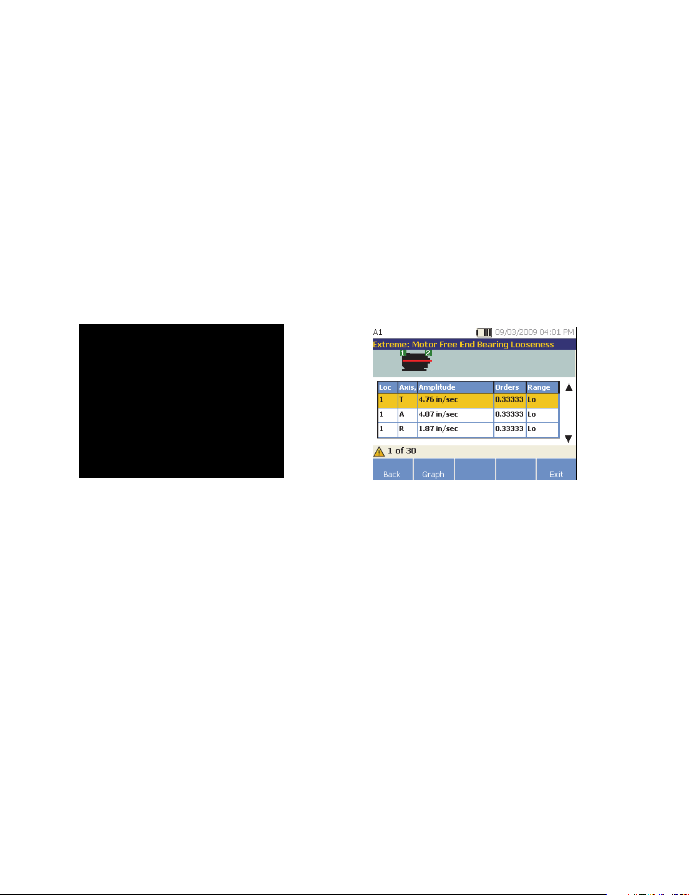
810
Users Manual
4-36
To view fault information:
1. In the fault list, use the Dial to highlight the fault.
gbk365.bmp
2. Push Details (F3). The Tester displays a table of
cited peaks for the selected fault. Each fault is
associated with at least one cited peak.
gbk67.bmp
Table 4-21 is a list of the details available for the
cited peaks table.
1.888.610.7664 sales@GlobalTestSupply.com
Fluke-Direct.com
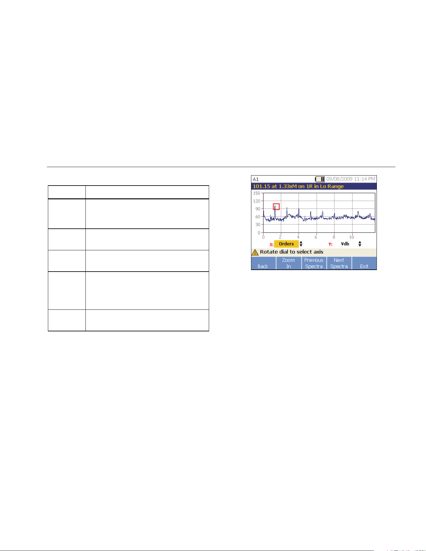
Operation
How to Diagnose
4
4-37
Table 4-21. Cited Peak Details
Label Description
Loc
Location of fault. Bearing locations are
numbered 1 to n, from free end of motor
(1) to end of drivetrain (n).
Axis
Direction of vibration signal: Axial, Radial,
or Tangential.
Amplitude
Vibration signal amplitude cited from this
specific location.
Orders
Multiples of the running speed or
frequency and identifies at which running
frequency that the cited amplitude peak is
detected.
Range
Frequency range of data collection, Hi or
Lo.
gbk66.bmp
Table 4-22 is a list of the softkey functions for the
Diagnosis Spectra screen.
1.888.610.7664 sales@GlobalTestSupply.com
Fluke-Direct.com

810
Users Manual
4-38
Table 4-22. Diagnosis Spectra Functions
Softkey Function
Back Go to the previous screen.
Zoom In
Zoom into the spectra. Push Zoom Out
to expand the view of the spectra. To
view the spectra in more detail, upload
the diagnosis data to a PC to review the
spectra with higher resolution. For more
information, see Chapter 5 Viewer
Software.
Previous
Spectra
Displays the spectra of previous cited
peak.
Next
Spectra
Displays the spectra of next cited peak.
Exit Exit to the Startup screen.
How to Access the Memory
You can sort the records in memory to make it easier to
find a specific record.
1. Push . The options are:
• View by machine setup
• View by measurement date
• View by last diagnosis
2. Use the Dial to scroll through and select the required
option.
3. Push Enter (F3) to select the option.
1.888.610.7664 sales@GlobalTestSupply.com
Fluke-Direct.com

Operation
How to Access the Memory
4
4-39
View by Machine Setup
Select View by machine setup, to view records sorted
by the Machine Setup. Use the Dial to highlight a specific
setup and push View (F4) to see the records for that
setup.
Table 4-23 is a list of the softkey functions for the Existing
Machine Setup screen.
Table 4-23. Existing Machine Setup Functions
Softkey Function
Back Go to the previous screen.
Delete Delete a Machine Setup.
Edit
Setup
Edit a Machine Setup. For more details
about Machine Setup, see the Machine
Setup section.
View
View the measurement details (measured
date and time) and diagnosis. For more
details about diagnosis, see How to
Diagnose.
Exit Exit to the Startup screen.
View by Measurement Date
Select View by measurement date to view the records
by the recorded date.
1. Use the Dial to select a date and push View (F4) to
see the machines measured on that date.
Table 4-24 is a list of the softkey functions for the
Measurement Date screen.
Table 4-24. Measurement Date Functions
Softkey Function
Back Go to the previous screen.
View
View the machine name with date and time
of measurement. (For more details about
measurement, see How to Measure
Vibration.)
Exit Exit to the Startup screen.
2. Scroll and select the machine with date and time.
The tester displays all the records for that date.
1.888.610.7664 sales@GlobalTestSupply.com
Fluke-Direct.com

810
Users Manual
4-40
Table 4-25 is a list of the softkey functions of View by
Measurement Date and Time screen.
Table 4-25. View by Measurement Date Functions
Softkey Function
Back Go to the previous screen.
Delete Delete the measurement details.
Diagnosis
Diagnose the measured data. For more
details about diagnosis, see How to
Diagnose.
Exit Exit to the Startup screen.
View by Last Diagnosis
Select View by last diagnosis to view the last diagnosis
recorded by the Tester.
See Table 4-20 for a list of the softkey functions for the
Diagnosis Faults screen.
1.888.610.7664 sales@GlobalTestSupply.com
Fluke-Direct.com

5-1
Chapter 5
Viewer Software
Title Page
Introduction .................................................................................................................... 5-3
System Requirements .................................................................................................... 5-3
PC Connections ............................................................................................................. 5-3
Install the Viewer Software ............................................................................................. 5-5
Uninstall the Viewer Software ........................................................................................ 5-5
Navigation ...................................................................................................................... 5-6
Preferences .................................................................................................................... 5-9
Application Settings ................................................................................................... 5-10
Upgrades ................................................................................................................... 5-11
Data Transfer ............................................................................................................ 5-11
Import Machine Setup ........................................................................................... 5-13
Export Machine Setup .......................................................................................... 5-15
Import Diagnostic Data ......................................................................................... 5-17
Export Diagnostic Data ......................................................................................... 5-19
Export Faults Data ................................................................................................ 5-21
Machine Setup ............................................................................................................... 5-25
Set Up a New Machine .............................................................................................. 5-25
1.888.610.7664 sales@GlobalTestSupply.com
Fluke-Direct.com

810
Users Manual
5-2
View Machine Setups ............................................................................................... 5-26
View Diagnosis .............................................................................................................. 5-29
View Other Data Files ............................................................................................... 5-33
Time Waveform ......................................................................................................... 5-34
Spectra ..................................................................................................................... 5-35
1.888.610.7664 sales@GlobalTestSupply.com
Fluke-Direct.com

Viewer Software
Introduction
5
5-3
Introduction
The Vibration Tester includes Viewer software that lets
you do tasks from a computer. With the basic features of
the software you can:
• import/export a Machine Setup from the Tester
• set up a new machine
• make a copy of a Machine Setup
• change a Machine Setup
• look at cited peaks graphs, vibration spectra, and
time waveforms
• zoom-in and zoom-out of data views
• make a backup of the diagnosis data from a
measured machine
• import and look at the thermographic image of a
machine
Additionally, you can configure the Machine Setups with
the software and export them to the Tester. This Machine
Setup procedure is much the same as the Machine Setup
wizard in the Tester. For external analysis of the fault
data, you can export the fault data, Machine Setup, and
diagnosis data, to send to a vibration test consultant.
System Requirements
The minimum PC system requirements to use the Viewer
software are:
• Operating system: Microsoft Windows 2000,
Windows XP, Windows Vista, Windows 7, or
Windows 8.1
• Minimum 1 GB RAM
• One USB port
• CD-ROM disk drive
PC Connections
To connect the computer to the Tester:
1. Power on the computer and the Tester.
2. Connect the USB cable to the USB ports of the
computer and the Tester as shown in Figure 5-1. See
the marking on the ends of the cable for identifying
the Type-A and Mini-B ends.
3. Install the supporting software and Viewer software
(if not installed already). See Install the Viewer
Software.
1.888.610.7664 sales@GlobalTestSupply.com
Fluke-Direct.com

810
Users Manual
5-4
gbk05.eps
Figure 5-1. Tester to PC Connections
1.888.610.7664 sales@GlobalTestSupply.com
Fluke-Direct.com

Viewer Software
Install the Viewer Software
5
5-5
Install the Viewer Software
To install the Viewer software:
1. Start the computer.
2. Put the User Documentation / Viewer Software
CD-ROM into the CD-ROM drive. The installation
automatically starts and the display shows a list of
software requirements before you can install the
Viewer software.
Note
If the installation does not start automatically,
browse through the CD-ROM and double-click
Setup.exe to start the installation.
The InstallShield Wizard extracts the Viewer software
components and Viewer Software Setup window
shows on the display.
3. Click Install to start the installation and then follow
the instructions on the screen to install the software.
You can accept the installation defaults.
After you finish, a Viewer Software entry appears in
the Start menu and a shortcut icon shows on the
Desktop.
Uninstall the Viewer Software
To uninstall the Viewer software:
1. Go to Start > All Programs > Fluke 810.
2. Click Uninstall Viewer Software.
To uninstall Microsoft .Net Framework 2.0, Microsoft .Net
Framework 3.5 SP1, Microsoft SQL Server 2005 Express,
Microsoft SQL Server Compact 3.5 SP1 and
ActiveSync 4.5:
1. Choose a method:
• For Windows XP, go to Start > Control Panel >
Add or Remove Programs.
• For Windows Vista and above, go to Start >
Control Panel > Programs > Uninstall a
program.
2. Choose the software to uninstall.
3. Click Uninstall.
4. Follow the online instructions to uninstall the
software.
1.888.610.7664 sales@GlobalTestSupply.com
Fluke-Direct.com

810
Users Manual
5-6
Navigation
To start the Viewer software:
1. Start the computer.
2. Click Start on the task bar.
3. Click All Programs.
4. Click Fluke 810 and then Viewer Software. Or,
double-click the Viewer Software icon on the
Desktop.
The startup screen shows on the display.
gbk85.bmp
1.888.610.7664 sales@GlobalTestSupply.com
Fluke-Direct.com

Viewer Software
Navigation
5
5-7
Table 5-1 is a list of the menu options and descriptions for the Viewer software.
Table 5-1. Viewer Software Navigation Menus
Menu Option Description
Transfer • Download the Machine Setup data from the Tester to the computer
• Upload the Machine Setup data from the computer to the Tester
• Download the diagnosis data from the Tester to the computer
• Import or Export diagnostic data
• Export the fault data to a PDF or Excel file
Machine Setup • Setup a new machine
• View a Machine Setup
• Make a copy of a Machine Setup
• Change a Machine Setup
• Remove a Machine Setup
• Export a Machine Setup to a PDF file
1.888.610.7664 sales@GlobalTestSupply.com
Fluke-Direct.com

810
Users Manual
5-8
Table 5-1. Viewer Software Navigation Menus (cont.)
Menu Option Description
View Diagnosis • View diagnosis
• View faults, recommendations, and cited peaks of a measurement
• View spectra by location and by cited peak
• View diagnostics from another computer
• Export diagnostic data to a PDF file
• Attach images to individual diagnostic data measurements
Preferences • Change application settings
• Upgrade the Tester firmware
• Delete history
• Backup or Restore data
• Enable or Disable Tester detection
Help Shows Viewer software help
1.888.610.7664 sales@GlobalTestSupply.com
Fluke-Direct.com

Viewer Software
Preferences
5
5-9
Preferences
Click the Preferences menu to open the submenus.
gbk121c.jpg
1.888.610.7664 sales@GlobalTestSupply.com
Fluke-Direct.com
810
Users Manual
5-10
Application Settings
You can change the display language, date format, and
time format with the Application Settings. To open the
Application Settings pane: click Application Settings.
The Application Settings pane shows on the right side of
the window. By default, Application Settings show when
you click the Preferences menu.
Table 5-2 is a list of the Application Settings.
Table 5-2. Application Settings
Option Description
Select
language
Select a language from the drop-down
list.
Select date
format
Select the date format as mm/dd/yyyy
or dd/mm/yyyy from the drop-down list.
Select time
format
Select the time format as 12Hrs or
24Hrs from the drop-down list.
Select unit
format
Select the measurement system as US
or Metric from the first drop-down list.
Next, select the measurement unit from
the second drop-down list.
Click Apply to save changes.
Click Home to go to the Viewer software
Home page.
1.888.610.7664 sales@GlobalTestSupply.com
Fluke-Direct.com

Viewer Software
Preferences
5
5-11
Upgrades
Periodically, upgrades are available for the Tester.
If you have
registered your Tester purchase, Fluke automatically
sends you an upgrade notice. For complete instructions
on how to do an upgrade, see Maintenance.
Data Transfer
The Viewer software interface lets you easily move data
and files between the Tester and a computer. You can:
• Import the Machine Setup from the Tester to the
Viewer software
• Export the Machine Setup from the Viewer software
to the Tester
• Import the diagnostic data from the Tester to the
Viewer software for enhanced views of the data
• Export diagnostic data
• Export the fault data to a PDF or Excel file
Note
You must connect the Tester to a computer to
see the Transfer menu options. The Device
Connectivity field shows the connection status
and the file path. See “PC Connections” for the
instructions on how to connect the Tester to a
computer.
To transfer data: click Transfer. The Transfer screen and
submenus show on the display.
1.888.610.7664 sales@GlobalTestSupply.com
Fluke-Direct.com

810
Users Manual
5-12
gbk88.bmp
1.888.610.7664 sales@GlobalTestSupply.com
Fluke-Direct.com

Viewer Software
Preferences
5
5-13
Import Machine Setup
You can import the Machine Setups from the Tester to
the Viewer software with the Import Machine Setup
submenu.
To import the Machine Setups:
1. Click Import Machine Setup. The Import Machine
Setup pane shows on the right side of the window.
By default, the Import Machine Setup option is
selected when you click the Transfer menu.
2. In the Select Date field, fill in the Start Date and the
End Date. Or, click
and use the calendar to click
on the date.
3. Choose a filter:
• Select ALL to see all the Machine Setups in the
Tester.
• Transferred to see the Machine Setups already
transferred from the Tester to the Viewer
software.
• Not Transferred to see the Machine Setups not
transferred from the Tester to the Viewer
software yet.
4. Click Filter. The Machine Setups show in the window
according to the filter selection. The Setup name,
Setup date, Record status (Complete or Incomplete),
Modified date, and the Transfer status (Transferred
to computer or not) for each record also shows in the
window.
Note
Click the list header to put the items in
ascending or descending order by date.
5. Click the checkbox before the Setup name to select a
Machine Setup.
Note
You cannot select a Machine Setup after it is
transferred.
6. Click
to import the Machine Setups to the
Viewer software. A prompt shows when the import is
done.
7. Click OK.
1.888.610.7664 sales@GlobalTestSupply.com
Fluke-Direct.com

810
Users Manual
5-14
gbk89.bmp
1.888.610.7664 sales@GlobalTestSupply.com
Fluke-Direct.com

Viewer Software
Preferences
5
5-15
Export Machine Setup
You can export the Machine Setups from the Viewer
software to the Tester with the Export Machine Setup
submenu.
To export the Machine Setups from the Viewer software:
1. Click Export Machine Setup. The Export Machine
Setup pane shows on the right side of the window.
The Tester IDs field shows the connected Tester ID.
If the Machine Setup is created in Viewer software,
the PC desktop entry also shows
2. Select PC desktop.
Note
If you choose the Tester ID and the “Not
Transferred” filter, the Machine Setups not
transferred from that Tester to the Viewer
software show in the Setup list.
3. In the Select date field, fill in the Start Date and the
End Date. Or, click
and use the calendar to click
on the date.
4. Choose a filter:
• Select ALL to see all the Machine Setups in the
Viewer software database.
• Transferred to see the Machine Setups already
transferred from the Viewer software to the
Tester.
• Not Transferred to see the Machine Setups not
transferred from the Tester to the Viewer
software yet.
5. Click Filter. The Machine Setups show in the window
according to the filter selection. The Setup name,
Setup date, Record status (Complete or Incomplete),
Modified date, and the Machine Setup status (setup
is present or not in the Tester) for each record also
shows in the window.
Note
Click the list header to put the items in
ascending or descending order by date.
6. Click the checkbox before the name to choose a
Machine Setup.
7. Click
to export the Machine Setups to the
Tester. A prompt shows when the export is done.
8. Click OK.
1.888.610.7664 sales@GlobalTestSupply.com
Fluke-Direct.com

810
Users Manual
5-16
gbk91.bmp
1.888.610.7664 sales@GlobalTestSupply.com
Fluke-Direct.com

Viewer Software
Preferences
5
5-17
Import Diagnostic Data
You can import the machine diagnosis data from the
Tester to the Viewer software for enhanced views of the
data. For example, you can magnify the spectra data to
see more detail.
To import the diagnosis data:
1. Click Import Diagnostic Data. The Import
Diagnostic Data pane shows on the right side of the
window.
2. In the Select date field, fill in the Start Date and the
End Date. Or, click
and use the calendar to click
on the date.
3. Choose a filter:
• Select ALL shows all the diagnosis details of
measured Machine Setups in the Viewer
software database.
• Transferred shows the diagnosis details of
measured Machine Setups that are already
transferred from the Tester to the Viewer
software.
• Not Transferred to view the diagnosis details of
measured Machine Setups that are not
transferred from Tester to the Viewer software
yet.
4. Click Filter. The Machine Setups show in the window
according to the filter selection. The Setup name,
Measurement ID, Measurement date, and the
Transfer status (Transferred to PC or not) for each
record also shows in the window.
Note
Click the list header to put the items in
ascending or descending order by date.
5. Click the checkbox before the Setup name to choose
a Machine Setup.
6. Click
to import the diagnostic data from the
Tester to the Viewer software. A prompt shows when
the import is done.
7. Click OK.
Note
The diagnostic data imported from the Tester is
view only. You cannot diagnose a machine with
the Viewer software.
1.888.610.7664 sales@GlobalTestSupply.com
Fluke-Direct.com

810
Users Manual
5-18
gbk93.bmp
1.888.610.7664 sales@GlobalTestSupply.com
Fluke-Direct.com

Viewer Software
Preferences
5
5-19
Export Diagnostic Data
You can export the diagnostic data in the computer with
the Export Diagnostic Data submenu. Then you can
send the exported file to a consultant for additional
analysis. To back up the diagnosis data:
1. Click Export Diagnostic Data. The Export
Diagnostic Data pane shows on the right side of the
window. The pane list includes the Setup Name,
Tester Serial No, and Measurement date.
Note
Click the list header to put the items in
ascending or descending order by date.
2. In the Select Date field, fill in the Start Date and the
End Date. Or, click
and use the calendar to click
on the date.
3. Click the checkbox before the Setup name to choose
the data.
4. Click
. A window opens for you to browse to the
destination folder.
5. Choose the folder. Or, click Make New Folder to
make a folder with a new name. The system prompts
you to include image files.
6. Click Yes to include image files or click No to keep
the file size smaller. The system prompts when the
export is done.
7. Click OK.
In the destination folder, data is saved in the .mdf
database file format. See View Other Data Files for
instructions about how to open the .mdf database
files.
1.888.610.7664 sales@GlobalTestSupply.com
Fluke-Direct.com

810
Users Manual
5-20
gbk95.bmp
1.888.610.7664 sales@GlobalTestSupply.com
Fluke-Direct.com

Viewer Software
Preferences
5
5-21
Export Faults Data
You can export the severity score for each fault and view
the files in PDF or Excel format. These formats are easy
to read, send to a printer, and send by email. In addition,
you can track data in Excel to see faults over time.
To change the fault data into PDF or Excel format:
1. Click Fa
ult data. T
he Fault Data pane shows on the
right side of the window.
2. To filter the data in the Filter by Testoer ID/ Machine
ID field:
• Select the specific testers from Tester ID.
• Select the machines from Machine ID. You can
export multiple machines.
• Select the measurements by date from
Measurement ID. You can export multiple
measurements.
• Select the start and end dates.
The faults selected by the IDs show in the fault list at
the bottom of the screen.
1.888.610.7664 sales@GlobalTestSupply.com
Fluke-Direct.com

810
Users Manual
5-22
gbk122.jpg
1.888.610.7664 sales@GlobalTestSupply.com
Fluke-Direct.com

Viewer Software
Preferences
5
5-23
3. To save as a PDF:
a. Click .
b. Browse to a location and save PDF file.
4. To save as an Excel spreadsheet:
a. Click
.
b. Browse to a location and save the Excel file.
c. You can export multiple machines and dates,
then cut and paste cells into a customized Excel
chart to show trends over time.
1.888.610.7664 sales@GlobalTestSupply.com
Fluke-Direct.com

810
Users Manual
5-24
gbk126.bmp
1.888.610.7664 sales@GlobalTestSupply.com
Fluke-Direct.com

Viewer Software
Machine Setup
5
5-25
Machine Setup
With the Viewer software, you can configure the Machine
Setups on the PC and then export to the Tester. The
setup sequence in the Viewer software closely follows
that of the Tester.
Note
See “Operation” for complete instructions about
Machine Setup.
Set Up a New Machine
You can make a new Machine Setup with the Viewer
software. The Machine Setup wizard walks you through
all the parameters to set up a vibration test. As you
continue through the setup, it is important to have the
correct data for each parameter. Setup fields will be
different when the inputs are different.
To setup a new Machine:
1. Click Machine Setup > Setup a new machine. The
Machine Setup pane shows on the right side of the
window.
In the Drive Train field, a sample image shows the
Machine Setup progress as the different parameters
become known.
2. Fill in a name for the machine in the Machine Name
field.
3. Click a motor type, AC or DC. Based on your
selection, the fields are different as you continue.
Note
See “Operation” for complete instructions about
Machine Setup.
4. Click Next to move through all the parameters.
5. Click Finish or
to save the Machine Setup. A
prompt shows when the setup is done.
Note
Before you export the Machine Setup, make
sure that the Tester to computer connection is
good.
6. Click OK.
7. Click . A copy of the new Machine Setup is
exported to the Tester. A prompt shows when the
export is done.
8. Click OK.
1.888.610.7664 sales@GlobalTestSupply.com
Fluke-Direct.com

810
Users Manual
5-26
gbk99.bmp
View Machine Setups
You can see all the Machine Setups you make with the
Viewer software in one window. The Viewer software also
shows if these Machine Setups have been transferred to
the Tester. You can Edit, Copy, Delete, and Export as a
PDF the Machine Setups.
To open the setups window:
1. Click Machine Setup > View Machine Setups. The
View Machine Setup pane shows on the right side of
the window.
2. Click PC desktop (default selection) on the left side
of the pane. The list of Machine Setups show with
their Record Status (Machine Setup is complete or
incomplete).
3. Click the Tester ID under Testers. The window
shows all the Machine Setups transferred from the
Viewer software to the Tester.
Note
Click the list header to arrange the items in
ascending or descending order by date.
1.888.610.7664 sales@GlobalTestSupply.com
Fluke-Direct.com

Viewer Software
Machine Setup
5
5-27
Table 5-3 is a list of the utilities for the View Machine
Setup window.
gbk103.bmp
1.888.610.7664 sales@GlobalTestSupply.com
Fluke-Direct.com
810
Users Manual
5-28
Table 5-3. View Machine Setup Utilities
Utility Function
(Edit) Click to open the Machine Setup wizard and change the Machine Setup. Click Finish or .
(Copy)
You can make copies only of the Machine Setups from the Tester. Click to open the Machine Setup
wizard and make a copy of a Machine Setup with a new name. As an option, you can change the
setup parameters.
Click Finish or
.
(Delete)
Click to remove a Machine Setup. A confirmation prompt shows.
Click Yes.
(Export) Click to make a PDF of the Machine Setup data.
(Delete All)
Click the checkbox in front of multiple Machine Setups.
Click to remove the Machine Setups. Or, click the checkbox on the list header to choose all the
Machine Setups at once.
Click
to remove all the Machine Setups.
1.888.610.7664 sales@GlobalTestSupply.com
Fluke-Direct.com

Viewer Software
View Diagnosis
5
5-29
View Diagnosis
After you complete the vibration tests on a machine, you
can import the diagnosis data to the computer and use
the Viewer software to see an enhanced view of the data.
The software filters let you set the parameters for the data
view.
To view diagnosis data:
1. Import the diagnosis data, see Import Diagnostic
Data.
2. Click View Diagnosis. The View Diagnosis pane
shows in the window (sample diagnosis data is
shown).
1.888.610.7664 sales@GlobalTestSupply.com
Fluke-Direct.com

810
Users Manual
5-30
gbk104.bmp
1.888.610.7664 sales@GlobalTestSupply.com
Fluke-Direct.com

Viewer Software
View Diagnosis
5
5-31
The left side of the pane is a list of the available
diagnosis data. This list is set up by the Tester name:
• Top level shows the Tester name
• Click + beside the Tester name to show the tests
(Test ID) that use that Tester
• Click + beside the Test ID to show the
Measurement ID
• Under the Measurement ID, you can find the
Measurement location, the Time Waveform, and
the Spectra for that location
gbk105.bmp
3. Click Clear Filter to remove the filter selections and
set to default.
4. Click Show Filter to open the Filters window. The
Tester ID field shows the Tester Name.
gbk106.bmp
5. Fill in the Start Date and the End Date. Or, click
and use the calendar to click on the date. This filter
shows the list of measurements made in this time
period.
1.888.610.7664 sales@GlobalTestSupply.com
Fluke-Direct.com

810
Users Manual
5-32
6. In the Select the severity field, click the severity level
as Extreme, Serious, Moderate, or Slight. This filter
shows a list of the faults with that severity level.
7. After selecting the filter options, click Filter.
With any measurement selection, the View Image button
appears. You use the View Image button to add the
Thermographic image to the diagnosis data of a
measurement.
To add a Thermal or jpg image:
1. Click View Image. A browse dialog box opens.
2. Click Browse.
3. Find the image (JPEG or .IS2 image format) within
the file structure.
gbk107.bmp
1.888.610.7664 sales@GlobalTestSupply.com
Fluke-Direct.com

Viewer Software
View Diagnosis
5
5-33
4. Click Upload to add the image to the diagnosis data
of the selected measurement. The Drive Train field
shows the illustration of the tested machine. The
CitedPeaks Details field shows the Faults from the
Machine.
5. Click the drop down arrow on the Fault to see each
cited peak and its Cited Peak number, Bearing, Axis
(Axial, Radial, or Tangential), Vibration amplitude,
Order, and Range (High or Low).
6. Click on a cited peak in the list to see its graph. The
Recommendations field shows a prioritized list of
troubleshooting tips for the faults.
gbk108.bmp
To make a PDF of the diagnosis data:
1. Click . A dialog to save the PDF file opens.
2. Save the PDF file. A dialog to open the file shows on
the display.
3. Select the file and click Open.
View Other Data Files
With the Viewer software, you can view the diagnosis
details from other data files that uses the .mdf file format.
To view backup data:
1. Click Other Data Files. The Open dialog box
shows on the display.
2. Browse to the .mdf database file that has the
diagnosis data.
3. Find and open the .mdf database file. You can view
the backup diagnosis data. See View Diagnosis for
more instructions.
4. Click Restore Main Database.
1.888.610.7664 sales@GlobalTestSupply.com
Fluke-Direct.com
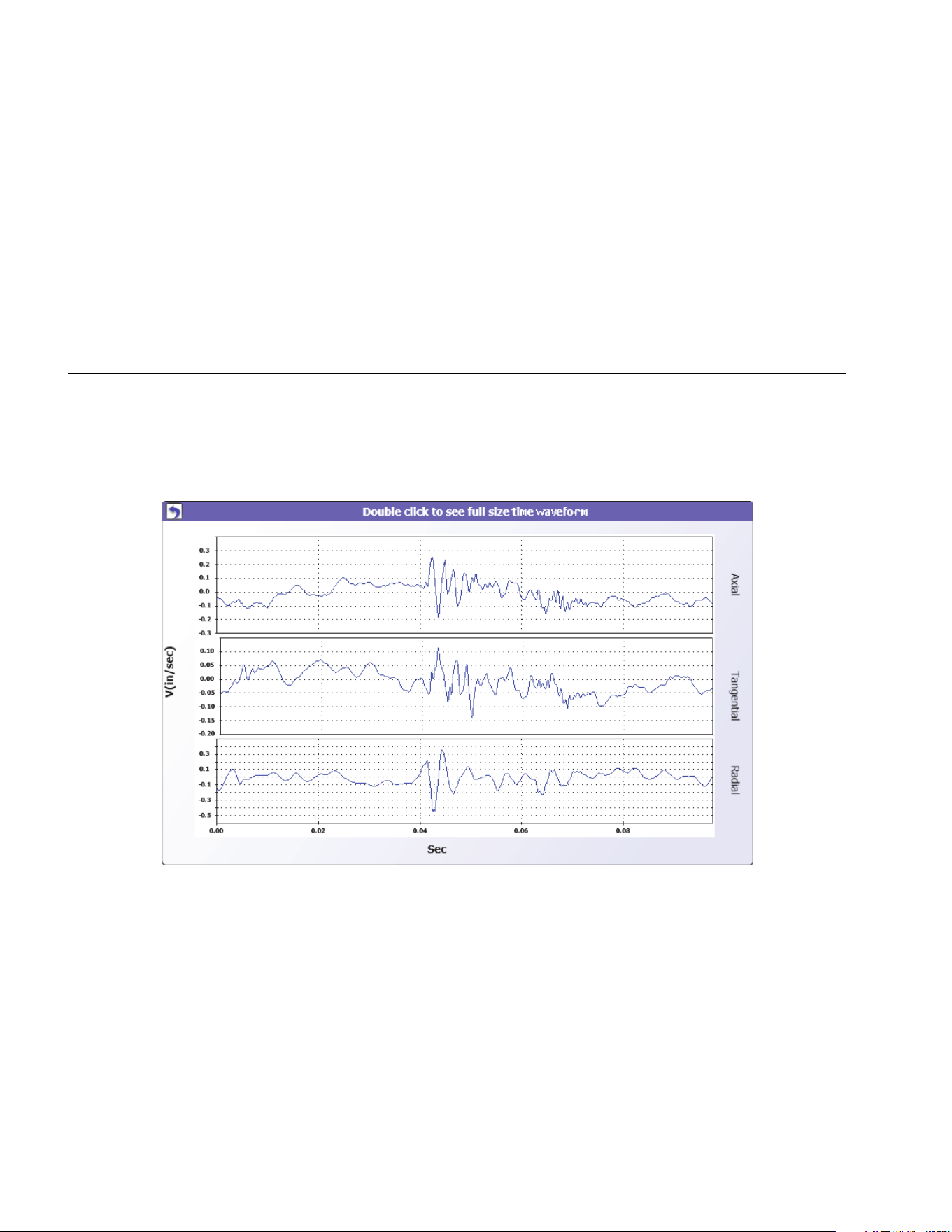
810
Users Manual
5-34
Time Waveform
A time waveform is available for each test location. You
must configure the system to save the raw time
waveform. With advanced wave form analysis training,
you can use pattern recognition in the time waveform to
detect different problems.
To open the time waveform window:
1. Click on the location of interest.
2. Click Time waveform on the right side of the pane.
gbk114.bmp
1.888.610.7664 sales@GlobalTestSupply.com
Fluke-Direct.com

Viewer Software
View Diagnosis
5
5-35
To zoom in and zoom out the time waveform:
1. Click on the waveform image.
2. Rotate the scroll button of the mouse.
To change the units:
1. Click the X-axis label.
2. Click the Y-axis label.
To go back to the View Diagnosis menu, click
.
Spectra
A 2-dimensional frequency plot, or spectra, is available
for each test location. The plot compares the axial,
tangential, and radial measurements.
To open the spectra window:
1. Click on the location of interest.
2. Click Spectra on the right side of the pane. The
Spectra window opens.
The High range (or wide range) of frequency is within a
spectrum of 0-100X. The Low range (or narrow range) of
frequency is within a spectrum of 0-10X.
To zoom in and zoom out the data plot:
1. Double-click the Spectra image.
2. Rotate the scroll button of the mouse.
To change the units:
1. Double-click the X-axis label to change the amplitude
units.
2. Double-click the Y-axis label to change the frequency
units.
To go back to the View Diagnosis menu, click
.
1.888.610.7664 sales@GlobalTestSupply.com
Fluke-Direct.com
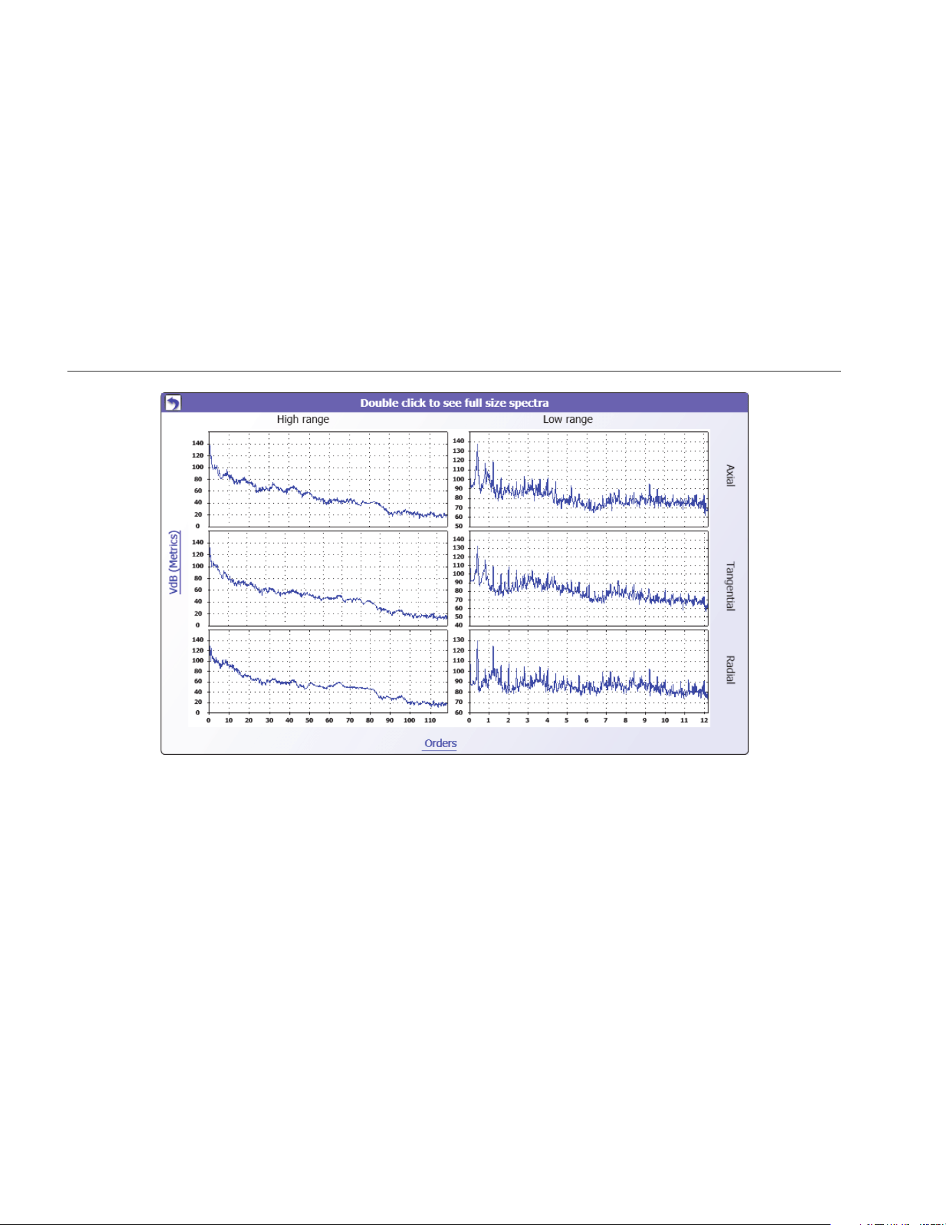
810
Users Manual
5-36
gbk109.bmp
1.888.610.7664 sales@GlobalTestSupply.com
Fluke-Direct.com

6-1
Chapter 6
Maintenance
Title Page
Introduction .................................................................................................................... 6-3
How to Clean .................................................................................................................. 6-3
Sensor Care ................................................................................................................... 6-3
Battery Replacement ...................................................................................................... 6-3
Vibration Tester Upgrades ............................................................................................. 6-5
How to Troubleshoot ...................................................................................................... 6-6
1.888.610.7664 sales@GlobalTestSupply.com
Fluke-Direct.com

Maintenance
Introduction
6
6-3
Introduction
Minimum maintenance is necessary for the Tester. Do not
hit, shake, or let the Tester fall as this can cause the
setup parameters to change.
Caution
No part of the Tester is serviceable by the
user. Do not attempt to open the Tester.
Caution
To prevent damage to the Tester or any
performance loss, do not put the Tester in
temperature extremes. The ambient
operating temperature is between 32 °F and
122 °F (0 °C and 50 °C) with a maximum
humidity of 90%.
How to Clean
Clean the external case of the Tester at regular intervals
with a moist cloth and a weak detergent solution.
Caution
To prevent damage or performance loss,
keep the Tester dry. Do not put the Tester
into any liquid. The Tester is not waterproof.
Sensor Care
Clean the Sensor cable at regular intervals with a damp
cloth and a weak detergent solution. Do not pull or push
the cable when you attach or remove the Sensor.
When a vibration test is done, always replace the Sensor
in the protective softcase.
Caution
To prevent damage to the inner piezoelectric
sensor, do not hit, shake, or let the Sensor
fall. A damaged Sensor decreases the
diagnostic quality.
Battery Replacement
To replace the battery:
1. Find the battery on the Tester, see Figure 6-1.
2. Push the battery notch up and pull out to remove the
battery.
3. To replace the battery, align the battery connector
and push the battery into the battery slot.
4. Lightly push the battery until it locks into the slot.
1.888.610.7664 sales@GlobalTestSupply.com
Fluke-Direct.com
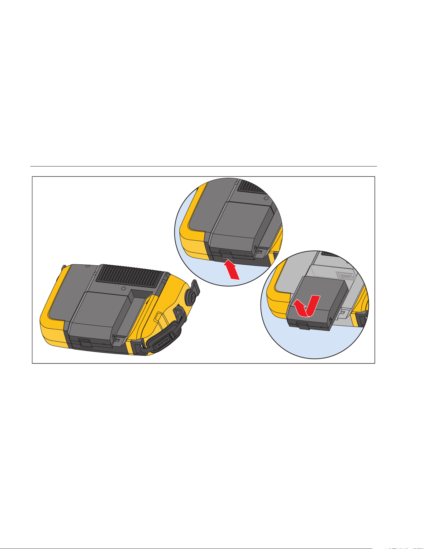
810
Users Manual
6-4
gbk12.eps
Figure 6-1. Battery Replacement
1.888.610.7664 sales@GlobalTestSupply.com
Fluke-Direct.com

Maintenance
Vibration Tester Upgrades
6
6-5
Vibration Tester Upgrades
Periodically, upgrades are available for the Tester.
If you have
registered your Tester purchase, Fluke will send an
upgrade notice to you automatically.
To upgrade the Tester:
1. Download the .CAB file for the Tester or diagnostic
engine
2. Launch the Viewer software application.
3. Click Preferences. The Preferences screen and
submenus show on the display.
4. Click Vibration Tester Upgrade. The Software
upgrade pane shows on the right side of the window.
5. Click Browse to select a .CAB file for the Vibration
Tester. A window opens for you to browse the .CAB
setup file.
gbk110.bmp
6. Click Transfer to Tester.
7. Click Browse to select .CAB file. A window opens for
you to browse the .CAB setup file.
8. Find the downloaded .CAB file within the file
structure.
9. Click Transfer to Tester.
10. Restart the Tester. Tester upgrades with the latest
software.
1.888.610.7664 sales@GlobalTestSupply.com
Fluke-Direct.com

810
Users Manual
6-6
How to Troubleshoot
Table 6-1 is a list of problems, causes, and corrective
actions for the Tester.
Table 6-1. Troubleshooting
Symptom Cause Corrective Action
Tester does not turn on. The battery is fully
discharged.
Connect the Tester battery to the ac adapter, connect to a
power source, and charge the battery.
If the problem continues, contact
technical support.
Battery charge does not
hold.
The battery is defective. A fully charged battery operates the Tester for 8 hours (under
normal operating conditions). Make sure that the battery is
charged. If the battery quickly discharges, replace the battery.
Tester cannot connect
with the Viewer Software.
The USB cable is not
connected correctly.
Correctly connect the USB cable. See PC Connection.
The USB cable is damaged. Examine the USB cable for any damage.
Front panel buttons /
softkeys do not operate.
Tester does not operate.
Push and hold the button to stop the Tester. Restart the
Tester.
1.888.610.7664 sales@GlobalTestSupply.com
Fluke-Direct.com

A-1
Appendix A
Frequently Asked Questions
This appendix is a compilation of the most frequently
asked questions about the Vibration Tester. More
information about the Tester is available
FAQs - Setup
1. Can I estimate values (RPM, hp, gear ratios,
etc) when setting up the machine or must I
provide exact information?
In order to provide a proper diagnosis, the user
should provide data that is as accurate as
possible.
2. How many characters can I use to create a
machine name?
The maximum machine name length is 15
characters.
3. Why is RPM critical to receiving a proper
diagnosis?
Entering an accurate running speed (RPM) is
critical to receiving a proper diagnosis. An
accurate running speed helps the Tester
accurately discern different fault conditions.
To obtain an accurate RPM value on a variable
speed drive use the laser tachometer and
reflective tape provided with the Tester or obtain
the frequency value from the drive controller
itself. To convert the frequency value to RPM,
calculate the following:
Hz * 60 = RPM
1.888.610.7664 sales@GlobalTestSupply.com
Fluke-Direct.com

810
Users Manual
A-2
4. On belt or chain driven components, how
can I estimate output RPM when I am unable
to obtain a tachometer reading?
Obtaining the RPM value using the laser
tachometer is the preferred method for
determining running speed. However, the output
RPM value can be calculated using simple
arithmetic. For simple reduction two-pulley
(sheave) systems, use the following formula and
solve for the RPM of the driven pulley:
Diameter, driver pulley (sheave)
Diameter, driven pulley (sheave) RPM, driver pulley (sheave)
RPM, driven pulley (sheave)
=
5. What happens if optional questions are not
answered during the machine setup?
To maximize the level of diagnostic confidence,
more information is always better than less.
Optional information, such as the number of
gear teeth or number of pump vanes, can often
be obtained through the component’s user
manual or direct from the manufacturer.
Choosing to skip optional questions in the
machine setup could potentially result in an
overdiagnosis of the component’s condition
(“false positive”).
6. Do gearboxes require any special setup in
the Tester?
To diagnose gearbox faults properly, you must
enter the shaft speeds, gear tooth counts or gear
ratios.
If selecting the shaft speed method for single
speed changers, it is critical to use the same
entry method (manual or tachometer) on both
input and output shafts.
For two or three-speed gearboxes, please refer
to the gearbox documentation or machine label
to determine gear ratios or gear tooth count.
7. What kinds of machinery can I diagnose with
the Tester?
The Tester can diagnose most common types of
rotating equipment, with the exception of
turbines, centrifuges (purifiers), diesel/gas
engines and generators. See the user’s manual
for a complete list of equipment. However, some
equipment may be called by another name but
could otherwise be setup within the Test. For
example, a simple mixer within a food
processing plant may have a drive train
composed of a motor, coupling, gearbox and
propeller pump. When considering whether a
particular piece of equipment can be diagnosed
with the Tester, break the equipment down into
its most basic components and determine
whether those components can be tested.
1.888.610.7664 sales@GlobalTestSupply.com
Fluke-Direct.com

Frequently Asked Questions
FAQs - Measurement
A
A-3
FAQs - Measurement
1. What are the effects of machine load and
condition?
The vibration from a drive train may change
depending on the load and the ambient
temperature of the motor. The one exception to
this rule is machines with misaligned driveshafts.
It is recommended to take vibration
measurements when the machine is running in a
steady state and at normal operating
temperature. For instance, taking
measurements from a machine where the load
regularly cycles or surges on or off is not ideal
(i.e. compressors). In these instances,
bypassing the process will be necessary to
ensure accurate and consistent diagnoses. In
the case of many compressors, the best
opportunity to take measurements is when the
tank is low, and the compressor is switched on.
The compressor will run longer in order to fill the
tank. Machines tested while still cold up may
have significantly different vibration signatures
than those at normal operating temperature as
temperature impacts shaft alignment and
operating clearances due to thermal expansion.
In the case of pumps, cavitation, air ingestion or
discharge pressure will influence vibration
readings and the diagnostic quality will be
affected. Pumps should not be tested with the
discharge valves closed; however, if they must
be tested in a recirculating condition, the
recirculating valve may be partially closed in
order to achieve a normal discharge pressure.
For larger machines, the general rule is to warm
up the machine for at least 30 minutes before
taking a measurement.
2. How do I mount the sensor?
When using a magnetically mounted sensor,
take care when attaching it to the test surface.
The magnet could pull the sensor assembly from
your hand and impact the test surface,
introducing excessive shock that could
permanently damage the sensor. Holding the
sensor firmly, carefully roll the sensor onto the
test surface to minimize the potential for impact.
1.888.610.7664 sales@GlobalTestSupply.com
Fluke-Direct.com

810
Users Manual
A-4
3. Which mounting option is the best?
The Tester’s diagnoses are largely dependent
upon the quality of vibration signal it receives
from the tested machinery. The method by which
a sensor is mounted to the machinery directly
affects the quality, accuracy and range of the
signal.
In general, permanent mounts (i.e. stud,
adhesive) yield the best results but are less
convenient. They should be used with machinery
that runs at high speeds and/or frequencies.
This includes machinery with a speed changer
(i.e. gearbox) resulting in an output shaft speed
of greater than 5x the input shaft speed,
machinery (i.e. vacuum pumps) where the
driving unit is running greater than 6000 RPM,
and centrifugal compressors, which typically
include an integrated speed changer. Permanent
mountings are also appropriate when desiring
consistent data tracked over time. Magnet
mounts are generally more convenient and
faster, making them the most widely used for
walkaround measurements, but some accuracy
will be sacrificed.
4. Can I use a single axis sensor?
The Tester can work with a single axis sensor
but it is recommended to use a tri-axial sensor to
improve diagnostic quality and for convenience:
using a tri-axial sensor can result in significant
cost and time savings as 3 different channels
are measured simultaneously, while single axis
sensors measure one axis at a time. If a single
axis sensor is connected, it is required to take at
least two measurements from each bearing
location to be able to diagnose data.
5. How can I select the right measurement
locations?
If the drive train is horizontal: Place the sensor
on the end, side, top or bottom of the equipment.
If the drive train is vertical: Place the sensor on
the front, back, side, top or bottom of the
components. For vertical drive trains, front, back
and sides are essentially the same. The first
placement will become the frame of reference
for the others. For example, once a location is
named “Front,” the “Back” and “Side” locations
become apparent. Make sure you use the same
reference for future measurements.
1.888.610.7664 sales@GlobalTestSupply.com
Fluke-Direct.com

Frequently Asked Questions
FAQs - Measurement
A
A-5
It is recommended to take two measurements
from each component in the drive train, if the
driving motor has more than 40 hp (30 kW) and
longer than 40 inches (102 cm) between
bearings. For equipment with less than 40 hp
and less than 40 inches between bearings, one
measurement is sufficient.
Quick Tips:
• Locate the sensor as close as possible to
the bearing, or on a solid structural member
leading to the bearing
• Sensor cable position should be parallel or
perpendicular to the drive shaft whenever
possible.
• Avoid mounting the sensor on thin surface
areas (i.e. fan shrouds) and cooling fins.
• Attach the sensor to a clean, flat, bare metal
surface if possible. Thick layers of paint,
grease, oil or other matter will reduce both
the holding force of the magnet and the high
frequency response of the sensor.
• For consistent diagnosis over time, it is
important to place the tri-axial Sensors at
the exact same orientation and location on a
machine before you take a measurement.
• Do not take bearing measurements from a
foundation or fabricated base.
• Do not mistake seal locations for a bearing
measurement location on pumps.
Note
Refer to the Quick Reference Guide for further
guidance on sensor locations.
6. Why is sensor orientation important?
The tri-axial sensor (provided with the Tester)
can collect vibration signals from three different
axes simultaneously. The orientation setup in
the Setup routine helps the Tester properly
correlate vibration signals to each of the three
axes. Mounting the sensor in different locations
and even changing the orientation by
90 degrees can cause a change in the
directional signal picked up from one channel of
the sensor. Therefore, it is critical to ensure the
sensor orientation setup in the Tester matches
the actual orientation of the sensor as placed on
the machinery.
1.888.610.7664 sales@GlobalTestSupply.com
Fluke-Direct.com

810
Users Manual
A-6
7. How do I orient the sensor?
The Tester uses the driveshaft (depicted as a
thick red line in the display) as the primary frame
of reference. Orient the sensor to the driveshaft
using the sensor cable where it exits from the
sensor, telling the Tester whether the cable is
parallel or perpendicular to the shaft.
Quick Tip:
The first time you take a measurement, draw or
paint a line on the machine indicating sensor
measurement location, with an arrow indicating
sensor orientation. This will aid in ensuring the
consistency of future measurements.
8. Will the diagnosis be impacted if I cannot
reach all the measurement locations?
You need to take at least one measurement
from each component in the drive train for
proper diagnosis. If a component is not tested
(except belts and couplings), the Tester cannot
diagnose the untested component.
9. When should I use the tachometer?
Using a tachometer is highly recommended for
Variable Frequency Drives (VFDs) DC Motors
and when RPM data is unavailable for regular
drives. Reflective tape placed on the rotating
equipment is required in order to capture
readings with the tachometer.
10. What should I do when the Tester gives an
accelerometer overload error?
Accelerometer overload is a common diagnostic
system error. Usually a temperature transient or
a loose sensor mounting can cause this error.
To isolate the problem, first eliminate bad cables
and improper sensor mountings. If the problem
is still not resolved after eliminating these issues,
1.888.610.7664 sales@GlobalTestSupply.com
Fluke-Direct.com

Frequently Asked Questions
FAQs - Diagnosis
A
A-7
FAQs - Diagnosis
1. How does the Tester diagnose the problems
and how accurate are the diagnoses?
Once the setup and measurement information is
collected, the onboard diagnostic system
analyzes the data using a set of powerful
algorithms. Using a database of similar
machines with no known faults, the diagnostic
system compares the tested machine’s setup
and newly acquired vibration data to similar
machines in the database.
Diagnostic quality is largely based upon the
quality and quantity of the machine setup and
data provided to the Tester. Proper component
descriptions coupled with proper sensor
placement and orientation, accurate running
speed measurements and answering all optional
questions in the machine setup will contribute to
higher confidence in the final diagnosis. While
accuracy can be provided for the Tester’s ability
to collect data (see Electrical Specifications),
many variables come into play to define a
reliable accuracy specification for the Tester’s
diagnostic capability. However, in independent
testing, the diagnostic capability of the Tester is
similar to that of an experienced vibration
analyst.
The diagnoses are based on experience with
similar machines. The Tester is part of an overall
decision-making process and should be used
alongside good judgment and knowledge of the
specific machine tested before taking specific
repair actions.
2. How should the severity scale be
interpreted? How long do I have before
failure?
The severity scale is based on the intensity of
the machine fault at the time of measurement. It
is not an indicator of time to machine failure. As
conditions change, the severity may change,
even appear to improve (for example,
immediately after lubrication). However, over
time, conditions will worsen with normal machine
wear and tear. Time to failure will vary
depending on the equipment type, age,
machine load, environmental conditions, and
other variables. It is not possible to correlate
each severity level with a certain time to failure.
Follow the recommended actions for each
severity level to avoid failure. In general, the
scale may be interpreted as follows:
1.888.610.7664 sales@GlobalTestSupply.com
Fluke-Direct.com

810
Users Manual
A-8
• Slight No repair action is
recommended. Monitor the
machine and retest after
regular machine planned
maintenance to verify
maintenance was performed
correctly.
• Moderate (Months, even up to a year) –
Repair action may be needed
in the future. A machine
failure is possible, so plan
accordingly. Increase the
frequency of vibration testing
on this equipment and review
spare parts availability.
• Serious (Weeks) – Repair action may
be needed before the next
planned downtime. There
may be other physical
evidence of the fault in terms
of noise or higher bearing
temperatures. Retest the
machine within a short period
to confirm finds. Limit the run
time of the machine, if
possible, and determine a
fault progression trend to
prevent additional component
failure.
• Extreme (Days) – Consider shutting
down the equipment and
taking repair action now to
avoid catastrophic failure.
There is likely other physical
evidence of the fault in terms
of noise, higher bearing
temperatures or visible
movement. Retest the
machine within a short period
to confirm finds.
1.888.610.7664 sales@GlobalTestSupply.com
Fluke-Direct.com

Frequently Asked Questions
FAQs - Diagnosis
A
A-9
3. The Tester says “serious” or “extreme” but
there is no indication of failure, what should I
do?
For extreme faults, users should be able to
sense impending failure through excessive
temperature, noise or visible movement. If there
are no physical indications of failure, it is
recommended to check the machine setup
inputs in the Tester and retake the
measurement. Improper machine setup,
incorrect running speed (RPM) or improper
measurement technique may result in an
inaccurate diagnosis. The diagnostic quality is
directly related to the quality and quantity of
information provided to the Tester.
4. The Tester says “slight” or “moderate,” but
there appears to be extreme vibration levels,
what should I do?
There are certain situations like a machine
installed on a flexible foundation where
excessive vibration can be detected. This type of
vibration is not necessarily bad, but is rather by
design.
It is still recommended to check the machine set
up input values and retaking the measurement if
there is any doubt with the diagnostic results.
5. What are some of the causes of bad data and
diagnosis?
The following will result in poor data collection
and inaccurate diagnoses:
• Improper speed input
• Improper machine setup
• Thermal transients, machine not up to
normal operating temperature
• Sensor overload, most often from not
allowing sensor to equalize in temperature
prior to collecting data
• Improper measurement locations
• Taking measurements from a machine that is
cycling or surging on and off
Confirm machine setup values and take
measurements again.
1.888.610.7664 sales@GlobalTestSupply.com
Fluke-Direct.com

810
Users Manual
A-10
6. What should I do when the Tester diagnoses
more than five serious or extreme faults?
If the Tester diagnoses more than five serious or
extreme faults, it is highly likely that a setup
input value is incorrect and the Tester is possibly
providing misleading diagnoses due to incorrect
information. Re-check the machine setup inputs,
specifically RPM values (if the exact speed is not
known, use the tachometer or view the drive
control panel). Retake the measurement and re-
analyze the data.
1.888.610.7664 sales@GlobalTestSupply.com
Fluke-Direct.com

B-1
Appendix B
Warning and Error Messages
Table B-1 is a list of the warning and error messages from the Tester. Table B-2 is a list of the warning and error messages
from the Viewer software.
Table B-1. Vibration Tester Warning and Error Messages
Display Message Description
Invalid RPM The RPM is out of range (the RPM range is 200 to 12000)
Tachometer not connected
The Tester cannot find the Tachometer. See “How to Connect the Tachometer” and make
the connections.
Tachometer laser not ON Tachometer laser is off. Push the Tachometer power button to on.
Failed to POWER ON
Tachometer
Power from the Tester is necessary for the Tachometer to operate. Make sure that the cable
connection is good. If the problem continues,
1.888.610.7664 sales@GlobalTestSupply.com
Fluke-Direct.com

810
Users Manual
B-2
Table B-1. Vibration Tester Warning and Error Messages (cont.)
Display Message Description
Failed to read RPM from
Tachometer
Tachometer cannot read the RPM of the machine. Follow the correct procedure to measure
the RPM.
Sensor not connected
The Tester cannot find the Sensor. See “How to Connect the Sensor” to make the
connections.
Failed to read Sensor type
The Tester cannot find the Sensor. See “How to Connect the Sensor” to make the
connections.
Cable is open
The Tester cannot find the Sensor. See “How to Connect the Sensor” to make the
connections.
Cable is short Cable or Sensor is bad. Change the cable or Sensor. Contac
Data acquisition failed
The Sensor mount method or measurement procedure is incorrect. See “How to Take a
Measurement” and “Sensor Mounting” for the correct procedure.
Measurement storage failed
The Tester memory is full. Make a data backup with the Viewer software and remove data
from the Tester memory.
Measurement time out
Allowed measurement time has been exceeded. The time to make a measurement is
30 minutes with triaxial Sensor and 45 minutes with single-axis Sensor. Make a new
measurement within the allowed time.
1.888.610.7664 sales@GlobalTestSupply.com
Fluke-Direct.com

Warning and Error Messages
B
B-3
Table B-1. Vibration Tester Warning and Error Messages (cont.)
Display Message Description
Invalid measure
The Tester cannot collect sufficient measurement data. Install the Sensor correctly, make
sure that the orientation of the Sensor is correct, and make a new measurement.
Diagnosis failed
The Tester cannot diagnose the measurement data. Make the measurement again. If the
problem continues, contact
Failed to perform self test
This message shows during a self-test. The Tester is defective, contact
Calibration past due. Last
calibration done on <Date>
Calibrate the Sensor. Contact
Set today’s date
The current date in the Tester is before the calibration date. Set the Tester to the current
date. See “Tester Settings.”
Battery low, please re-
charge
Connect the Tester battery to the ac adapter, connect into a power source, and charge the
battery. See “How to Charge the Battery.”
Sensor failure
This message shows during the self-test. The Sensor is defective. Contact
Tachometer failure
This message shows during the self-test. The Tachometer is defective. Contact
1.888.610.7664 sales@GlobalTestSupply.com
Fluke-Direct.com

810
Users Manual
B-4
Table B-1. Vibration Tester Warning and Error Messages (cont.)
Display Message Description
Failed to perform self test
This message shows during the self-test. The Tester is defective. Contact
Data transfer not successful
This message shows if the Tester cannot connect to the Viewer software. Make sure that the
connection is good between the Tester and computer.
Contact Service
Center
An error occurred in the Tester. Turn the Tester off and then on. If the message is frequent,
contact
Table B-2. Viewer Software Warning and Error Messages
Display Message Description
Application encountered an
error.
An error occurred in the Viewer software. Restart the Viewer software application.
Invalid file The Viewer software cannot read the file type.
Installation file format is
wrong
The upgrade file is defective or invalid.
Tester connection is lost
This message shows if the connection breaks between the computer and the Tester during
data transfer. Correctly connect the USB cable.
1.888.610.7664 sales@GlobalTestSupply.com
Fluke-Direct.com

C-1
Appendix C
Glossary
Acceleration. The rate of change of velocity, often
depicted as “g’s” or in “mm/s2” in the metric system or
“in/sec2” in the English system. Acceleration is not
constant but will vary through the vibration cycle, reaching
maximum levels as velocity reaches its minimum. This is
typically when a particular mass has decelerated to a stop
and is about to begin accelerating again.
Accelerometer. A transducer whose electrical output
responds directly to acceleration. Accelerometers
typically cover a much wider frequency range, allowing
them to pick up signals not present with other types of
transducers. Due to their frequency range,
accelerometers are ideal for most types of rotating
equipment, making them the most commonly used
transducer for vibration measurements.
Alignment. A condition where components within a drive
train are parallel or perpendicular, according to design
requirements. The Tester can diagnose misalignment
conditions where these components are no longer aligned
according to design requirements, causing excessive
bearing wear and power consumption in the machine.
Amplitude. The size or the magnitude of the vibration
(displacement or velocity or acceleration). Peak-to-peak,
zero-to-peak or Root Mean Square (RMS) can be used to
express velocity terms. In general, “Peak-to-peak” is used
for displacement, “Zero-to-Peak” is used for velocity and
RMS is used for acceleration. In the Tester’s diagnostic
details, amplitude indicates the magnitude of each cited
peak in velocity terms.
Axial. One of the three vibration axes (Radial, Tangential
and Axial), the axial plane is parallel to the centerline of a
shaft or turning axis of a rotating part.
1.888.610.7664 sales@GlobalTestSupply.com
Fluke-Direct.com

810
Users Manual
C-2
Balancing Resonance Speed(s). A rotating speed that
corresponds to a natural resonance frequency.
Balanced Condition. For rotating machinery, a condition
where the shaft’s geometric centerline coincides with the
mass centerline.
Balancing. A procedure for adjusting the radial mass
distribution of a rotor so that the mass centerline
approaches the rotor geometric centerline.
Blocking. The installation of a permanently affixed
mounting block is known as “blocking” a machine.
Cited Peak. An abnormal vibration magnitude/level
identified (or cited) by the Fluke 810 diagnostic engine.
Cited Peaks are marked with red in the Tester and in the
Viewer Software. Each fault diagnosed can be related to
several cited peaks.
CPM. Cycles per minute. Cycles per minute is a measure
of the number of times a particular event occurs within a
one minute period. Used as the horizontal axes of the
spectra and time waveform plots within the Tester.
Displacement. When measuring machinery vibration,
displacement represents the actual distance the vibration
causes the part in question to move. It is measured in
thousandths of an inch (mils) in the English system and in
millimeters (mm) in the metric system.
Frequency. The number of events that occur within a
fixed time period, frequency is also calculated as the
reciprocal of time (for example, one divided by the time
interval). Frequency is typically expressed in terms of
Hertz (Hz), but can also be expressed as cycles per
minute (cpm) or revolutions per minute (RPM) when
multiplying Hz times 60. It can also be represented as
multiples of turning speed, or "orders," where frequency
in RPM is divided by the turning speed of the machine.
Frequency Domain. Since vibration exists within the time
domain, a vibration signal is represented as a time wave
form if viewed on an oscilloscope. If plotted, the time
waveform would represent a plot of amplitude vs. time. If
the waveform were transformed to the frequency domain,
the result would be a spectrum representing a plot of
amplitude vs. frequency.
Imbalance. A condition on rotating equipment where the
center of mass does not lie on the center of rotation.
Imbalance can severely reduce bearing life as well as
cause undue machine vibration.
Looseness. Mechanical looseness can be either of two
types: rotating and non-rotating. A rotating looseness is
caused by excessive clearance between rotating and
stationary elements of the machine such as in a bearing.
Non-rotating looseness is a looseness between two
normally stationary parts, such as a foot and a
foundation, or a bearing housing and a machine.
1.888.610.7664 sales@GlobalTestSupply.com
Fluke-Direct.com

Glossary
C
C-3
Misalignment. In machines, perfect alignment occurs
when the centerline of two coupled shafts coincide. When
they do not coincide, misalignment exists. Angular
misalignment is when the centerline of the two shafts
intersect but are not parallel. Parallel misalignment is
when the centerline of the two shafts are parallel but not
concentric.
Mounting Pad. Mounting pads (bronze or stainless steel)
can be placed at appropriate measurement locations on
machines using an industrial adhesive. The triaxial
accelerometer is attached to these pads for data
collection. The pad ensures a good transfer of vibration
data to the transducer by providing a strong and
consistent mounting location.
Orders. With regards to rotating equipment, orders are
multiples or harmonics of the running speed (or
associated reference component). For example, 1X
means “one times running speed.”
Piezoelectric Element. Any transducer (sensor) that
uses a piezoelectric substance as an active element.
Examples are force transducers, accelerometers,
pressure transducers, and phonograph pickup cartridges.
Radial. One of the three vibration axes (Radial,
Tangential and Axial), the radial plane represents the
direction from the transducer to the center of the shaft on
rotating equipment. For typical horizontal machines, radial
equals the vertical axis. For horizontal machines radial
refers the horizontal axis upon which the accelerometer is
attached.
Range (Frequency). Frequency range of data collection.
Hi indicates the High or wide range of frequency within a
spectrum (i.e. 0-100X). Lo indicates the Low or narrow
range of frequency within a spectrum (i.e. 0-10X).
Running Speed. The speed, usually expressed in
revolutions per minute (RPM), at which a rotating
machine runs. It may also be expressed in Hz by dividing
RPM by 60.
Sensor. Transducer, or accelerometer, whose output is
directly proportional to acceleration. Piezoelectric
elements are most commonly used to produce the
Sensor’s output.
Signature. The signature, usually called the vibration
signature, is the overall vibration pattern of a machine. It
is said that the vibration signature contains more
information about the machine than any other
nondestructive test can discover.
Spectrum. Plural Spectra. The plot of the vibration
signal’s amplitude (y –axis) against frequency (x-axis),
also referred to as the “vibration signature,” an “FFT” or
“spectral plot”. Vibration signals can be transformed from
the time domain (amplitude against time) to the frequency
domain (amplitude against frequency) by using the Fast
Fourier Transform (FFT) method. A spectra simplifies
vibration data interpretation as certain vibration
1.888.610.7664 sales@GlobalTestSupply.com
Fluke-Direct.com

810
Users Manual
C-4
amplitudes can be closely related to the running speed of
the machinery. The diagnostic technology in the Tester
identifies the mechanical problems depicted in the
spectra and cites the abnormal magnitudes.
Tachometer. A device for indicating rotation speed.
Tangential. One of the three vibration axes (Radial,
Tangential and Axial), the tangential plane is positioned
90 degrees to the radial plane, running tangent to the
driveshaft. For typical horizontal machines, tangential
equals the horizontal axis. For typical vertical machines
tangential equals the second horizontal axis
perpendicular to the mounting of the accelerometer.
TEDS. A Transducer Electronic Datasheet (TEDS) is a
technology that enables communication of the Sensor
type to the Tester. TEDS works with the Tester to ensure
the Sensor performs at its specified sensitivity, ensuring
optimal performance, and reminds the user when the
Sensor needs to be calibrated.
Time Waveform. The plot of a vibration signal in the time
domain with the signal’s amplitude (y-axis) against time
(x-axis). The time waveform represents the signal as
directly captured from the Sensor. The Tester does not
store time waveforms unless users opt to capture them
within the Tester’s settings. Time waveforms can only be
viewed in the Viewer software and they can be exported
to a file if further analysis is desired.
VdB (Velocity in Decibels). VdB is a logarithmic scale
referencing 0 VdB=10E-8 meter per second. This scale is
used for US measurements.
VdB* (Velocity in Decibels). VdB* is a logarithmic scale
referencing 0 VdB=10E-9 meter per second. This scale is
used for SI/metric measurements.
Velocity. Velocity is the rate of change in position,
measured in distance per unit of time. When measuring
vibration signals, velocity also represents the rate of
change in displacement and is expressed in inches (in) or
millimeters (mm) per second.
VFD (Variable-Frequency Drive). A VFD is a system for
controlling the rotational speed of an alternating current
(AC) electric motor by controlling the frequency of the
electrical power supplied to the motor.
Vibration. Vibration is the oscillation of a point, an object,
or a part of an object around a fixed reference, or rest,
position. An object can vibrate as a unit, in which case it
is called “whole body vibration”, or, as is usually the case,
an object can vibrate in a complex way where it deforms
and different parts of it vibrate at different frequencies and
amplitudes.
1.888.610.7664 sales@GlobalTestSupply.com
Fluke-Direct.com
