
Ma
y 2012, Rev. 2, 12/14
© 2012-2014 Fluke Corporation. All rights reserved. Specifications are subject to change without notice.
All product names are trademarks of their respective companies.
805/805 FC
Vibration Meter
Users Manual
1.888.610.7664 sales@GlobalTestSupply.com
Fluke-Direct.com

LIMITED WARRANTY AND LIMITATION OF LIABILITY
Each Fluke product is warranted to be free from defects in material and workmanship under normal use and service. The warranty period is
one year and begins on the date of shipment. Parts, product repairs, and services are warranted for 90 days. This warranty extends only to
the original buyer or end-user customer of a Fluke authorized reseller, and does not apply to fuses, disposable batteries, or to any product
which, in Fluke's opinion, has been misused, altered, neglected, contaminated, or damaged by accident or abnormal conditions of operation
or handling. Fluke warrants that software will operate substantially in accordance with its functional specifications for 90 days and that it has
been properly recorded on non-defective media. Fluke does not warrant that software will be error free or operate without interruption.
Fluke authorized resellers shall extend this warranty on new and unused products to end-user customers only but have no authority to
extend a greater or different warranty on behalf of Fluke. Warranty support is available only if product is purchased through a Fluke
authorized sales outlet or Buyer has paid the applicable international price. Fluke reserves the right to invoice Buyer for importation costs of
repair/replacement parts when product purchased in one country is submitted for repair in another country.
Fluke's warranty obligation is limited, at Fluke's option, to refund of the purchase price, free of charge repair, or replacement of a defective
product which is returned to a Fluke authorized service center within the warranty period.
To obtain warranty service, contact your nearest Fluke authorized service center to obtain return authorization information, then send the
product to that service center, with a description of the difficulty, postage and insurance prepaid (FOB Destination). Fluke assumes no risk
for damage in transit. Following warranty repair, the product will be returned to Buyer, transportation prepaid (FOB Destination). If Fluke
determines that failure was caused by neglect, misuse, contamination, alteration, accident, or abnormal condition of operation or handling,
including overvoltage failures caused by use outside the product’s specified rating, or normal wear and tear of mechanical components,
Fluke will provide an estimate of repair costs and obtain authorization before commencing the work. Following repair, the product will be
returned to the Buyer transportation prepaid and the Buyer will be billed for the repair and return transportation charges (FOB Shipping
Point).
THIS WARRANTY IS BUYER'S SOLE AND EXCLUSIVE REMEDY AND IS IN LIEU OF ALL OTHER WARRANTIES, EXPRESS OR
IMPLIED, INCLUDING BUT NOT LIMITED TO ANY IMPLIED WARRANTY OF MERCHANTABILITY OR FITNESS FOR A PARTICULAR
PURPOSE. FLUKE SHALL NOT BE LIABLE FOR ANY SPECIAL, INDIRECT, INCIDENTAL, OR CONSEQUENTIAL DAMAGES OR
LOSSES, INCLUDING LOSS OF DATA, ARISING FROM ANY CAUSE OR THEORY.
Since some countries or states do not allow limitation of the term of an implied warranty, or exclusion or limitation of incidental or
consequential damages, the limitations and exclusions of this warranty may not apply to every buyer. If any provision of this Warranty is
held invalid or unenforceable by a court or other decision-maker of competent jurisdiction, such holding will not affect the validity or
enforceability of any other provision.
1.888.610.7664 sales@GlobalTestSupply.com
Fluke-Direct.com

i
Table of Contents
Title Page
Introduction .................................................................................................................... 1
How to Contact Fluke .................................................................................................... 1
Safety Information .......................................................................................................... 2
Symbols ......................................................................................................................... 3
Accessories ................................................................................................................... 3
Specifications ................................................................................................................ 3
Before You Start ............................................................................................................ 5
Unpack and Inspect .................................................................................................. 5
Storage ..................................................................................................................... 5
Battery ...................................................................................................................... 5
Controls and Connections ......................................................................................... 6
Measurement Status LEDs ....................................................................................... 7
Power On .................................................................................................................. 8
Power Off .................................................................................................................. 8
How to Operate.............................................................................................................. 9
Navigation ................................................................................................................. 9
Meter Configuration .................................................................................................. 9
Units ..................................................................................................................... 10
Time ..................................................................................................................... 10
Date ..................................................................................................................... 11
1.888.610.7664 sales@GlobalTestSupply.com
Fluke-Direct.com

805/805 FC
Users Manual
ii
Backlight Timeout ................................................................................................. 11
Language ............................................................................................................. 11
Device Info ........................................................................................................... 12
Battery Selection .................................................................................................. 12
Emissivity Selection .............................................................................................. 12
Power Saving ............................................................................................................ 13
Flashlight ................................................................................................................... 13
Accessory Connectors .............................................................................................. 13
External Sensor .................................................................................................... 14
Audio (805 only) ................................................................................................... 15
USB ...................................................................................................................... 16
About Measurements ..................................................................................................... 17
Crest Factor+ (High Frequency Measurement) ......................................................... 18
Quick Measurement .................................................................................................. 19
Overall Vibration (Low Frequency) Measurement with Severity Scale ...................... 20
Machine Category ................................................................................................ 21
Create New Setup ..................................................................................................... 22
Add to Setup ........................................................................................................ 24
Enable Fluke Connect (805 FC only) ........................................................................ 24
How to Save a Measurement .................................................................................... 25
Auto Save ............................................................................................................. 25
Save to Existing Setup ......................................................................................... 25
Save to Current Setup .......................................................................................... 26
Save to New Setup ............................................................................................... 26
How to Recall a Setup for Measurements ................................................................. 27
Access to Memory ......................................................................................................... 28
View All Data ............................................................................................................. 28
View Setups .............................................................................................................. 29
Edit Setups ................................................................................................................ 29
Clear All Data ............................................................................................................ 30
Interpret Results ............................................................................................................ 31
Severity Scale ........................................................................................................... 31
ISO 10816 Standards ................................................................................................ 32
Trending .................................................................................................................... 32
1.888.610.7664 sales@GlobalTestSupply.com
Fluke-Direct.com

Vibration Meter
Contents (continued)
iii
ISO 10816-1 ......................................................................................................... 32
ISO 10816-3 ......................................................................................................... 33
ISO 10816-7 ......................................................................................................... 33
Export Data .................................................................................................................... 34
General Maintenance .................................................................................................... 37
Care .......................................................................................................................... 37
How to Clean ............................................................................................................ 37
Battery Replacement ................................................................................................ 38
Firmware Upgrades ....................................................................................................... 39
How to Troubleshoot ...................................................................................................... 40
1.888.610.7664 sales@GlobalTestSupply.com
Fluke-Direct.com

805/805 FC
Users Manual
iv
1.888.610.7664 sales@GlobalTestSupply.com
Fluke-Direct.com

v
List of Tables
Table Title Page
1. Symbols ................................................................................................................................ 3
2. Accessories .......................................................................................................................... 3
3. Keypad and Connectors ....................................................................................................... 6
4. LED Status ............................................................................................................................ 7
5. Crest Factor+ ........................................................................................................................ 18
6. Severity Scale ....................................................................................................................... 31
7. Vibration Severity - ISO 10816-1 .......................................................................................... 32
8. Troubleshooting .................................................................................................................... 40
1.888.610.7664 sales@GlobalTestSupply.com
Fluke-Direct.com

805/805 FC
Users Manual
vi
1.888.610.7664 sales@GlobalTestSupply.com
Fluke-Direct.com

vii
List of Figures
Figure Title Page
1. Meter Controls and Connections .......................................................................................... 6
2. Flashlight .............................................................................................................................. 13
3. External Sensor Connection (805) ........................................................................................ 14
4. Audio Connection (805 only) ................................................................................................. 15
5. Meter to PC Connection (805) .............................................................................................. 16
6. Measurement Display ........................................................................................................... 17
7. Import Database ................................................................................................................... 34
8. Plot Options .......................................................................................................................... 35
9. Data Plot Graph .................................................................................................................... 36
10. Battery Replacement ............................................................................................................ 38
1.888.610.7664 sales@GlobalTestSupply.com
Fluke-Direct.com

805/805 FC
Users Manual
viii
1.888.610.7664 sales@GlobalTestSupply.com
Fluke-Direct.com

1
Introduction
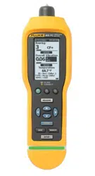
The 805/805 FC Vibration Meter (the Meter or Product) is
a screening tool for bearings and overall vibration
measurements on machines. The Meter includes these
features:
• Overall vibration measurem
ent
•
Bearing health measurement with Crest Factor
+
•
On-screen severity sca
les
•
Acceleration, Velocity, and Displaceme
nt units of
measure
•
Temperature measurement with spot IR sensor
• Test results export to MS Exce
l template
• Belt Holster
• IP54
•
Language support for Chinese (Simplified), Dani
sh,
Dutch, English, Finnish, F
rench, German
, Italian,
Jap
anese, Norwegian, Portuguese (Brazilian), Russi
an
Spanish, Swe
dish, and Turkish
• Audio output (805 on
ly)
• Flashli
ght
• Stores up to 3,500 record
s
• USB
support
•
Storage/
shipping case
• External accelerometer support
• Wireless data transmission of most rece
nt
measurement
for use with Fluke Connect Phone A
pp
(805 F
C
only)
How to Contact Fluke
To contact Fluke, call one of the following telephone
numbers:
• Technical Support USA: 1-800-44-FLUKE
(1-800-443-5
853)
•
Calibration/Repair USA: 1-888-99-FLUKE
(1-888-993-5
853)
•
Canada: 1-800-36-FLUKE (1-800-363-5
853)
• Europ
e: +31 402-675-200
•
Jap
an: +81-3-6714-3114
•
Singapo
re: +65-6799-5566
• Anywhere in the world: +1-425-446-550
0
1.888.610.7664 sales@GlobalTestSupply.com
Fluke-Direct.com

805/805 FC
Users Manual
2
Safety Information
A Warning identifies the conditions and procedures that
are dangerous to the user. A Caution identifies the
conditions and procedures that can cause damage to the
Product or the equipment under test.
Warning
To prevent possible electrical shock, fire, or
personal injury:
• Carefully read
all instructions.
• Do not
touch hazardous voltages wi
th the
Product. The
se voltages could cause injury
or death.
• Use the Pro
duct only as specified
, or the
prote
ction supplied by the product ca
n be
compromised.
• Examine the
case before you
use the
Product. Lo
ok for crack
s or missing
plastic.
• Make sur
e the battery is securely
in
position be
fore operation
.
• Do not u
se the Product around explosive
gas, vapor, or in damp or we
t
env
i
ronments.
• Comply
with local and national safety
codes. Use personal protective equipm
ent
(appr
oved rubber gloves, face protec
tion,
and flame
-resistant clothes) to preven
t
shock a
nd arc blast injury wh
ere
haza
rdous live conductors are expos
ed.
To prev
ent personal injury from the infrared
thermometer:
• See emissivity information for ac
tual
temper
atures. Reflective objects resu
lt in
lo
wer than actual temper
ature
measurem
ents. These objects pose
a burn
haza
rd.
• Do not keep the product in opera
tion and
unattend
ed at high temperatures.
To prevent personal injury when near rotating
equipment:
• Use caution around rotating equipmen
t.
• Keep c
ords and straps containe
d.
1.888.610.7664 sales@GlobalTestSupply.com
Fluke-Direct.com
Vibration Meter
Symbols
3
Symbols
Table 1 is a list of symbols on the Meter and in this
manual.
Table 1. Symbols
Sy
mbol Des
cription
Important information. See manual.
Hazardous voltage.
Conforms to requirements of European Union and
European Free Trade Association.
Conforms to relevant Australian EMC standards
This product complies with the WEEE Directive
(2002/96/EC) marking requirements. The affixed
label indicates that you must not discard this
electrical/electronic product in domestic household
waste. Product Category: With reference to the
equipment types in the WEEE Directive Annex I,
this product is classed as category 9 "Monitoring
and Control Instrumentation” product. Do not
dispose of this product as unsorted municipal
waste. Go to Fluke’s website for recycling
information.
Battery or battery compartment.
Low battery when shown on display.
Conforms to relevant South Korean EMC
standards.
Accessories
Table 2 is a list of the accessories available for the Meter.
Table 2. Accessories
Description
PN
Belt Holster 4106625
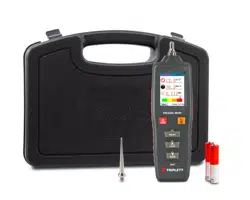
Storage/Shipping Case 4094432
Battery Door 4059351
USB Cable 3563901
Specifications
Sensor
Sensitivity (typical) .............................. 100 mV / g ±10 %
Measurement Range .......................... 0.01 g to 50 g
Frequency Range ............................... 10 Hz to 1,000 Hz
and 4,000 Hz to 20,000 Hz
Resolution ........................................... 0.01 g
Accuracy (typical) ................................ At 100 Hz: ±5 % of measured
value
Amplitude Units
Acceleration ................................ g, m/sec
2
Velocity ....................................... in/sec, mm/sec
Displacement .............................. mils, μm
1.888.610.7664 sales@GlobalTestSupply.com
Fluke-Direct.com

805/805 FC
Users Manual
4
Infrared Thermometer
Temperature Measurement
Range ................................................. -20 °C to 200 °C (-4 °F to 392 °F)
Accuracy (typical)
-20 °C to 120 °
C
(-4 °F to 248
°F) .............................. ±2 °C (4 °F)
120 °C to 160 °C
(248 °F to 320 °F) ........................... ±3 °C (6 °F)
160 °C to 200 °C
(320 °F to 392 °F) ........................... ±4 °C (7 °F)
Note
The specified accuracy is applicable only when the Meter is in
thermal equilibrium with its environment. Accuracy is not
specified when the target temperature is more than 20
°
C
(36
°
F) below the temperature of the Meter.
Focal length ........................................ Fixed, at ~3.8 cm (1.5 in)
External Sensor
Frequency Range ............................... 10 Hz to 1,000 Hz
Bias Voltage (to supply power) ........... 20 V DC to 22 V DC
Bias Current (to supply power) ........... 5 mA
Note
Fluke supports, but does not provide, external sensors.
Vibration Meter
Low Frequency Range
(overall measurement) ........................ 10 Hz to 1,000 Hz
High Frequency Range
(CF+ measurement)............................ 4,000 Hz to 20,000 Hz
Vibration Limit .................................... 50 g peak (100 g peak-peak)
Battery Type ....................................... AA (2) lithium non-rechargeable
3 V dc
Battery Life
805 .................................................. 250 measurements
805 FC, Fluke Connect enabled .. 210 measurements
A/D Converter ..................................... 16-bit
Sampling Rate
Low Frequency ............................... 20,000 Hz
High Frequency ............................... 80,000 Hz
Signal to Noise Ratio .......................... 80 dB
Real Time Clock Backup ..................... Coin Battery
Size (L x W x H) .................................. 24.1 cm x 7.1 cm x 5.8 cm (9.5 in x
2.8 in x 2.3 in)
Weight ................................................. 0.40 kg (0.89 lb)
Connectors (805) ................................ USB Mini-B 7-pin, Stereo Audio
Output Jack (3.5 mm Audio Plug),
External Sensor Jack (SMB
connector)
Connectors (805 FC) .......................... USB Mini-B 7-pin, External Sensor
Jack (SMB connector)
Firmware
External Interfaces .............................. USB 2.0 (full speed)
communication
Data Capacity ..................................... Database on internal flash memory
Upgrade .............................................. through USB
Memory ............................................... Up to 3,500 measurements
Environmental
Operating Temperature ....................... -20 °C to 50 °C (-4 °F to 122 °F)
Storage Temperature .......................... -20 °C to 60 °C (-4 °F to 140 °F)
Operating Humidity ............................. 10 % to 95 % RH (non-
condensing)
1.888.610.7664 sales@GlobalTestSupply.com
Fluke-Direct.com

Vibration Meter
Before You Start
5
Operating/Storage Altitude ................. Sea Level to 3,048 meters
(10,000 feet)
IP Rating ............................................. IP54
Vibration Limit ..................................... 500 g peak
Drop Test ............................................ 1 meter
Electromagnetic Environment
IEC 61326-1: Portable
FCC ................................................ CFR Title 47, Part 15, Subpart B
Korea (KCC) ................................... Class A Equipment (Industrial
Broadcasting & Communication
Equipment)
This product meets requirements for industrial (Class A)
electromagnetic wave equipment and the seller or user should take
notice of it. This equipment is intended for use in business
environments and is not to be used in homes.
Before You Start
This section helps you to know the Meter parts, controls,
connections, and status LEDs.
Unpack and Inspect
Carefully unpack and inspect the:
•
Vibration
Mete
r
• Storage
case
•
USB Cable
•
Quick Reference Guide
•
Belt Holster
•
AA (2) Lithium non-rechargeable batteri
es
Storage
When not in use, always keep the Meter in the supplied
storage case. The custom interior of the case supplies
protection for the Meter, documentation, and accessories.
Battery
Before you use the Meter for the first time, install the two
AA lithium non-rechargeable batteries (included). See
Battery Replacement on page 38 for more information.
The Meter also operates on two AA alkaline (3 V)
batteries. Due to short battery life, alkaline batteries are
not recommended.
Note
Set the battery type in the Device Settings menu.
See page 12.
shows on the display when battery power is low.
Replace the batteries before you continue to use the
Meter.
1.888.610.7664 sales@GlobalTestSupply.com
Fluke-Direct.com
805/805 FC
Users Manual
6
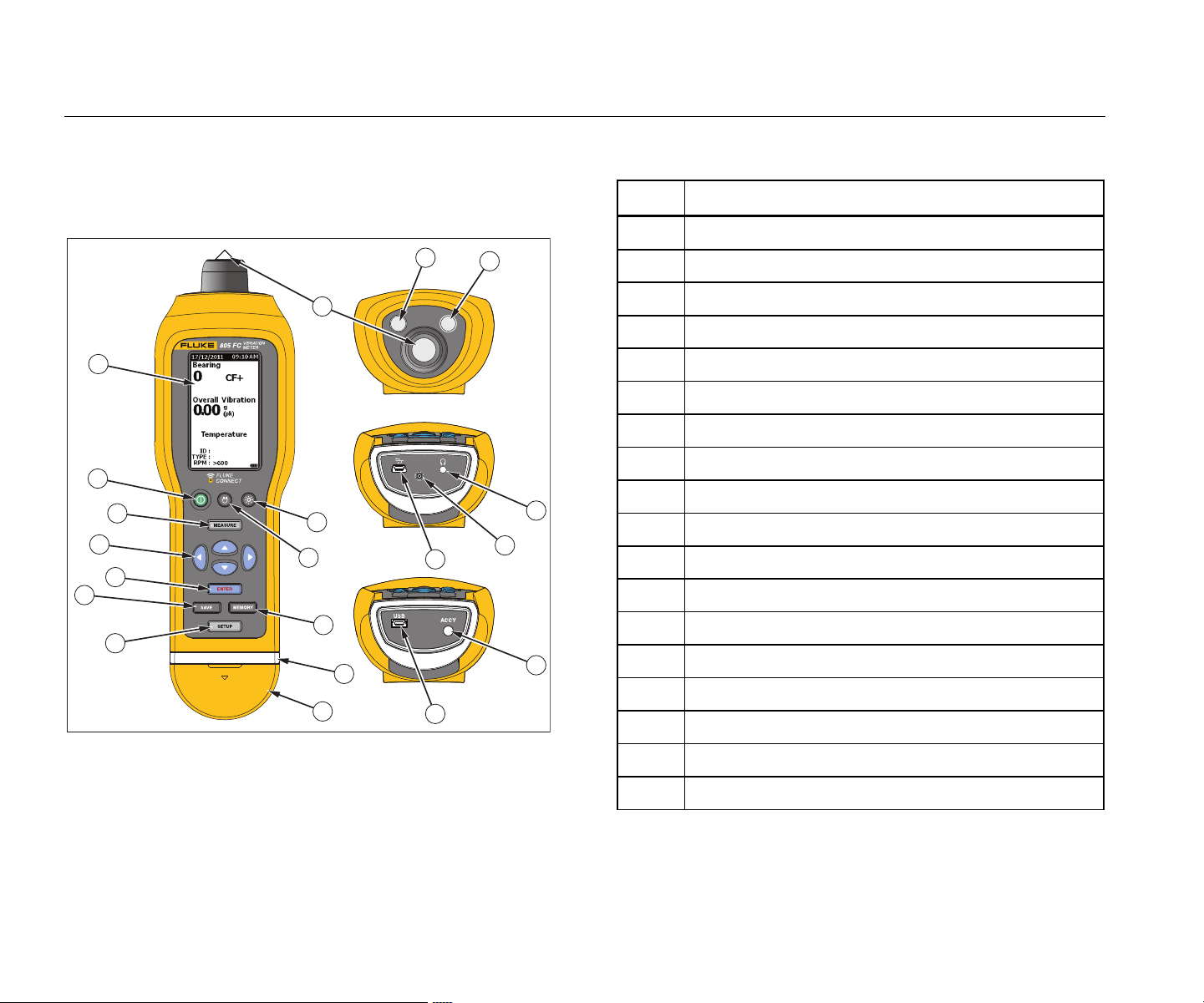
Controls and Connections
Figure 1 shows the location of the controls and
connections for the Meter. Table 3 is a key.
1
2
3
4
5
7
8
9
10
11
12
15
18
17
14
13
14
13
6
16
gqi01.eps
Figure 1. Meter Controls and Connections
Table 3. Keypad and Connectors
Item Control
LCD
Power on/off
Measure
Navigation
Enter
Save
Setup
Connector cover
Status LED
Memory
Flashlight on/off
Backlight on/off
USB port
External sensor port
Audio port (805 only)
Vibration sensor
IR temperature sensor
Flashlight
1.888.610.7664 sales@GlobalTestSupply.com
Fluke-Direct.com
Vibration Meter
Before You Start
7
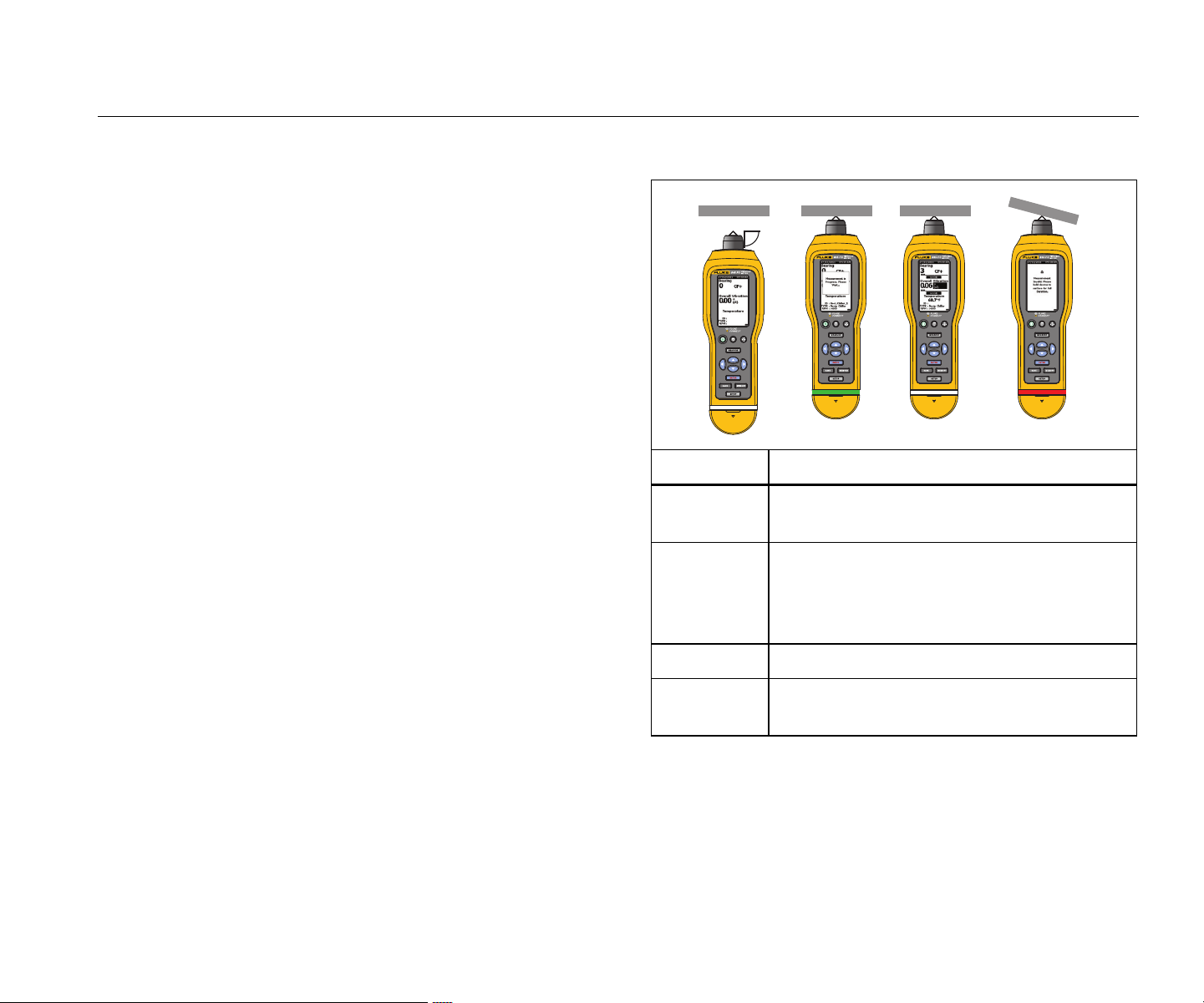
Measurement Status LEDs
The Meter has a status light for visual feedback about the
measurement. Green and red LEDs show the
measurement status and that a good measurement has
been taken. Table 4 is a list of the status as the LED
changes color.
Table 4. LED Status
90˚
gqi07.eps
Status Description
Green Off
Push . Meter is ready for data
measurement.
Green On
Push the sensor tip onto the test surface,
on solid metal, as close as possible to the
bearing. Apply the compression force until
green LED is off.
Green Off Data measurement is complete.
Red On
Error, insufficient force or time duration, no
data measurement.
1.888.610.7664 sales@GlobalTestSupply.com
Fluke-Direct.com
805/805 FC
Users Manual
8
Power On
Push to turn on the Meter. See Table 3 for the control
location.
Note
Before you use the Meter for the first time, install
the new batteries (see Battery Replacement on
page 38).
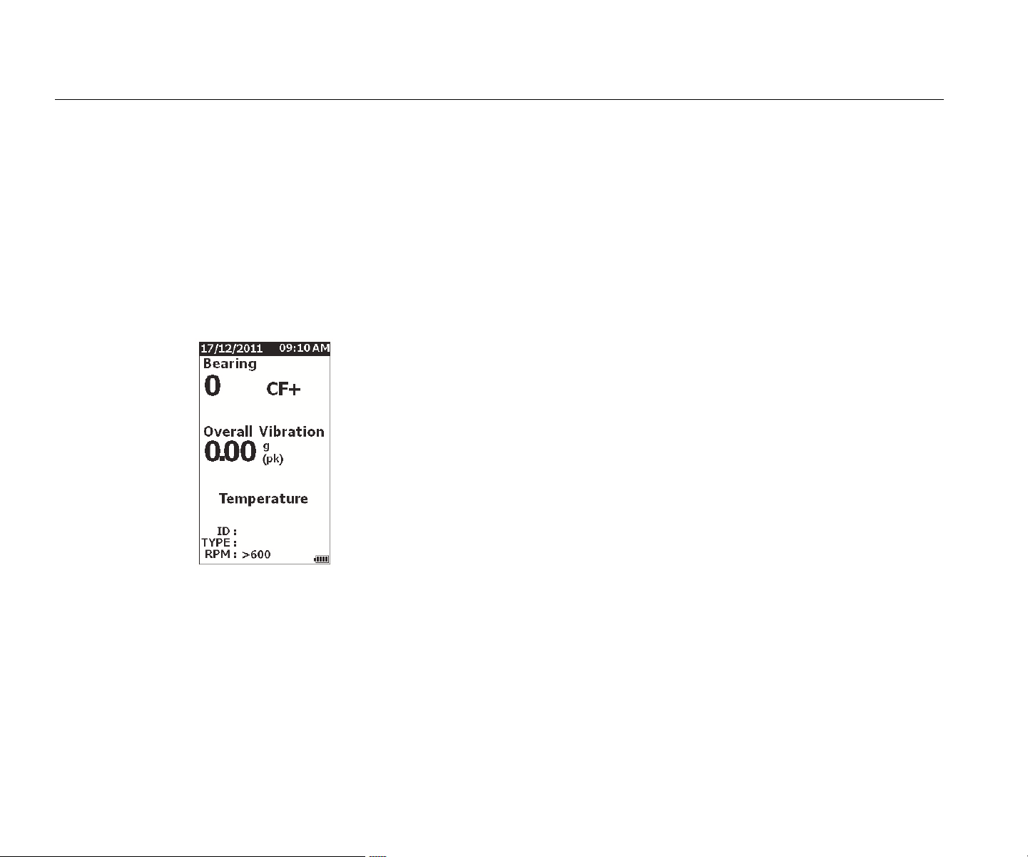
When the Meter is turned on, the default Measurement
screen shows on the Meter.
gqi49.jpg
Power Off
A soft shutdown is the preferred method to turn off the
Meter:
1. Push .
2.
At the prompt, select Yes
.
3. Or,
select No to continue with operation
.
If the Meter locks up o
r becomes inoperable, a hard
shutdown can be used to turn off the Meter:
Note
Use a hard shutdown only as a last recourse as it
can cause data loss. After a hard shutdown, start
the Meter and verify the data in Memory.
1.
Push and hold for more than 2 seconds.
2. Push to res
t
art the Meter.
If Meter does
not restart or the problem persis
ts,
c
ontact Fluk
e.
1.888.610.7664 sales@GlobalTestSupply.com
Fluke-Direct.com

Vibration Meter
How to Operate
9
How to Operate
This section is about the operation of the Meter. It includes
measurement tips and step-by-step instructions.
Navigation
For general operation:
moves the cursor through the menu options
and edits the options
opens next menu or sets the selection
updates the Meter with a new selection setting
recalls the previous menu
Each menu has navigation hints for its content at the
bottom of the screen.
Meter Configuration
The Setup menu is how you change the configuration of
the Meter. You can change these Device Settings:
•
Units
•
Time
• Date
• Backli
ght Timeout
•
Lang
uage
•
Device Info
• Battery Selection
To open
Device Settings:
1. Push t
o view the Setup screen
.
2. Push
and to highlight Dev
ice Settings
from
the menu. Thi
s opens a list of all available options
.
3. Push
to o
pen the menu.
4. Push and to highligh
t
an option.
5. Push
to o
pen the menu.
1.888.610.7664 sales@GlobalTestSupply.com
Fluke-Direct.com
805/805 FC
Users Manual
10
Units
The units of measure are adjustable for different
standards.
To set from the Device Settings menu:
1. Push and to highlight Units.
2. Push
to o
pen menu for units. The curre
nt
setting is hi
ghlighted.
3. Push and to highligh
t the unit to chang
e.
4. Push
to o
pen menu with options
for that
unit. The cu
rrent setting is highlighted
.
5. Push
t
o update the Meter an
d exit the
menu.
6. Push and to move to the next page for more
option
s
.
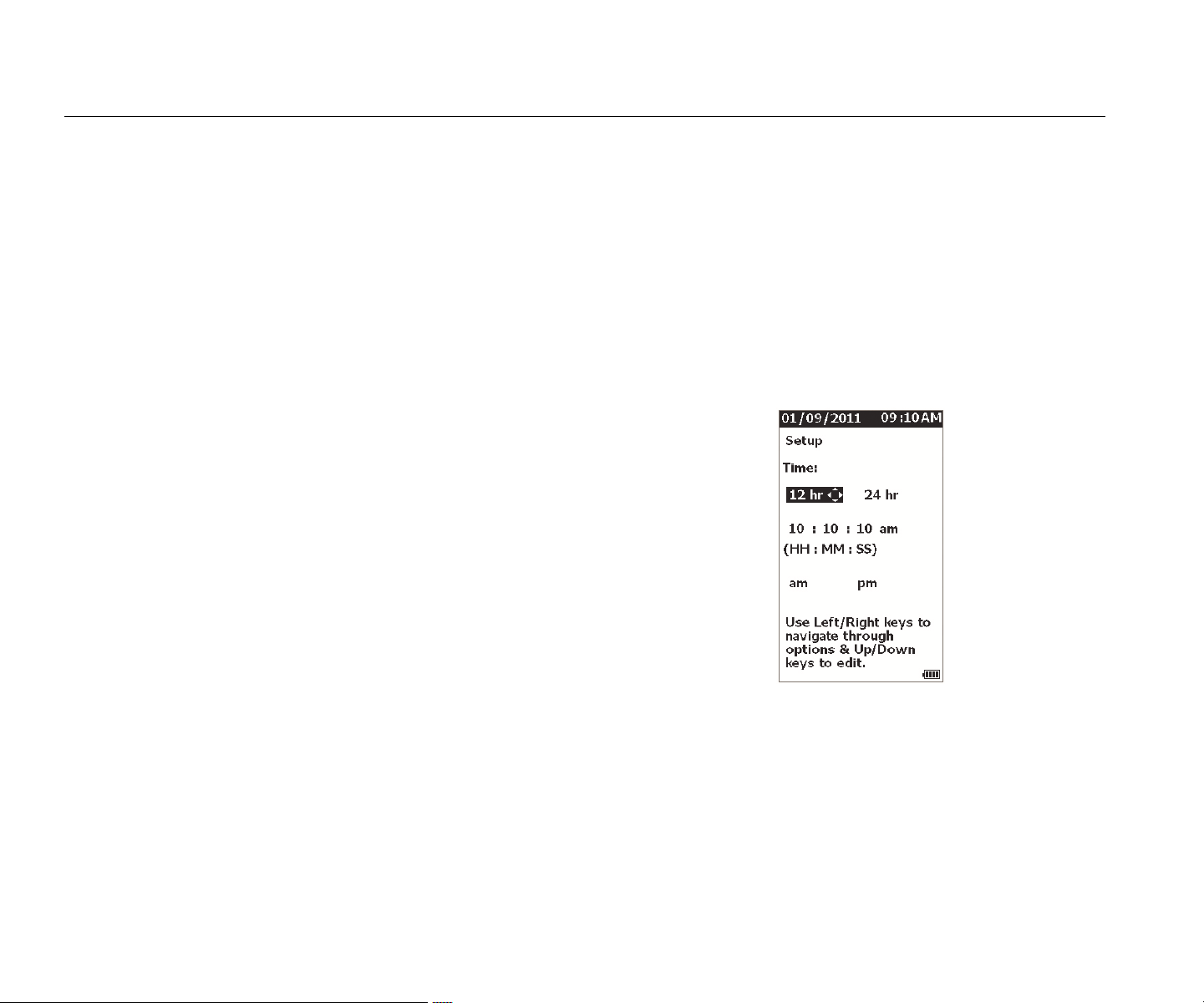
Time
To set the time format:
1. Push and to highlight the format a
s 12 hr
or
24 hr.
2. Push to set the option.
To s
et the time:
1. Push and to high
light hour, mi
nute, or
se
cond.
2. Push to e
nable the ed
it.
3. Push
and to make a
change.
4. Push to set the option.
5. Push
and to highlight am or pm.
6. Push
to set the option.
gqi57.jpg
7. Push to update the Meter and exit the
menu.
1.888.610.7664 sales@GlobalTestSupply.com
Fluke-Direct.com

Vibration Meter
How to Operate
11
Date
To change the date format:
1. Push and to highligh
t
the option for
MM/DD/YYY
Y or DD/MM/YYYY.
2. Push to set the option.
To cha
nge the date:
1.
Push to highlight the option for Day, Mont
h, and
Year.
2. Push to e
d
it the option.
3. Push
and to make a
change.
4. Push to
set the change
.
5. Push
t
o update the Meter an
d exit the
menu.
Backlight Timeout
The backlight turns off in a preset time limit. If you do not
push a key during this time limit, the backlight turns off to
extend battery power. To turn on the backlight, push a key.
You can also set the backlight as always on with the None
option.
To change the backlight timeout:
1. Push and to highligh
t the option: 2 min
,
5 min, 10 min, or None.
2. Push
to
set the option.
3. Push
t
o update the Meter an
d exit the
menu.
Language
To change the language for the display:
1. Push and to highligh
t a languag
e.
2. Push
to set the option and exit the menu.
3. Push
t
o update the Meter an
d exit the
menu.
The display shows the ne
w language.
1.888.610.7664 sales@GlobalTestSupply.com
Fluke-Direct.com

805/805 FC
Users Manual
12
Device Info
Information about your Meter is in the Device Info menu.
This information includes the:
•
Serial
numbe
r
•
Software
version
• Emissivity value (See Emissivity Selection
for more
informatio
n on
the emissivity value.)
•
Internal sensor se
nsitivity
•
Database Free Spac
e
Battery Selection
To change the battery type:
1.
Go to the Device Settings menu.
2. Push and to highlight Batter
y Selection
.
3. Push
to o
pen the menu.
4. Push and to highligh
t
the battery type you
have in the Meter.
5. Push t
o update the Meter an
d exit the
menu.
Emissivity Selection
The correct emissivity value is important for you to make
the most accurate temperature measurements. Most
painted or oxidized surfaces have an emissivity of 0.93
(default value set in the Meter). This is correct for non-
contact temperature measurements on most bearing
housings.
Inaccurate measurements can result from shiny or
polished metal surfaces. To compensate, put masking
tape or flat black paint on the measurement surface. Make
sure that the tape is the same temperature as the
measurement surface before you make a measurement.
For other applications the Meter has additional preset
emissivity values:
•
Aluminum
(e=0.30)
•
Iron
(e=0.7
0)
• Steel
(e=0.80)
• Paint (e=0.93) – default value
•
Woo
d (e=0.94)
•
Conc
rete
(e=0.95)
1.888.610.7664 sales@GlobalTestSupply.com
Fluke-Direct.com
Vibration Meter
How to Operate
13
To change the emissivity value:
1.
Go to the Device Settings menu.
2. Push and to highlight Material Emissiv
ity
.
3. Push
to o
pen the menu.
4. Push and to highligh
t
a value.
5. Push
t
o update the Meter an
d exit the
menu.
Power Saving
The Meter bypasses battery power when it is connected to
a PC with the USB cable. The Meter then uses the PC
power to extend its battery power.
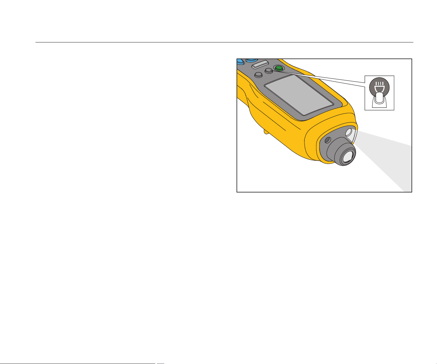
Flashlight
The Meter has a built-in flashlight to illuminate the
measurement area on the machine. Push to turn on
and off the flashlight. See Figure 2 for the location of this
button.
Note
Flashlight operation for extended periods of time
decreases battery life. Flashlight operation will
affect a temperature measurement.
gqi06.eps
Figure 2. Flashlight
Accessory Connectors
The Meter has three accessory connectors:
•
External
Sens
or
•
Audio (805 on
ly)
• USB
1.888.610.7664 sales@GlobalTestSupply.com
Fluke-Direct.com
805/805 FC
Users Manual
14
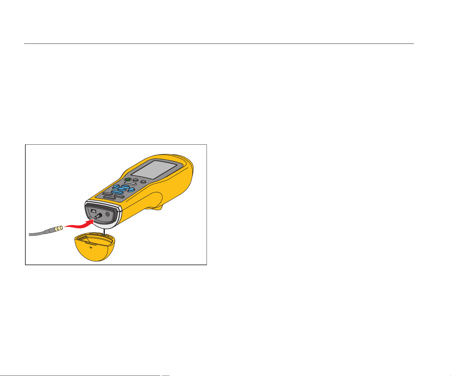
External Sensor
In addition to the integrated vibration sensor, an optional
external sensor connects to the Meter. The connector type
for the external sensor is a Subminiature version B (SMB).
Figure 3 shows how to connect an external sensor to the
Meter.
Note
Fluke supports, but does not provide, external
sensors.
gqi05.eps
Figure 3. External Sensor Connection (805 shown)
Note
High frequency measurement (Crest Factor+) and
Temperature measurement automatically turn off
when an external sensor is connected to the
Meter.
To connect:
1.
Open the connector cover and push the
external
s
ensor into position.
2. Push to open the E
nter Sens
itivity menu.
Note
You must set the sensitivity in mV/g units.
3.
Use the navigation keys to select a characte
r in
the menu.
4. Push
to input the c
harac
ter into the field.
5.
Repeat steps 2 and 3 for additional characters.
6. Push
t
o store th
e value in the Meter and exit
the menu.
7. Push to start data
collectio
n.
The Mete
r automatically detects when you disconnect the
external sensor and is set to measure with the internal
sensor.
1.888.610.7664 sales@GlobalTestSupply.com
Fluke-Direct.com
Vibration Meter
How to Operate
15
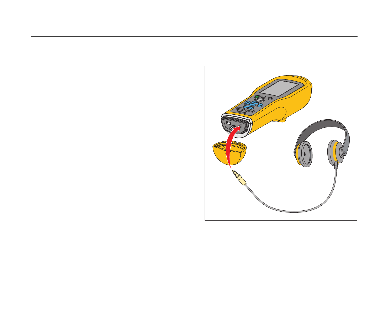
Audio (805 only)
The Meter has an audio connector for headphones.
Headphones are useful for detection of unusual machine
sounds.
To listen to a machine:
1.
Open the connector cap of the Meter and connec
t
the audio
connecto
r.
2.
Put on the headphones.
3.
Push and continue to hold
.
4.
Push the sensor tip onto the test surface.
As you continue to hold and Meter position
with a co
nsistent force, the audio channe
l is
active. The M
eter also takes a measurem
ent at
this time.
Figure 4 shows how to make the audio connection to the
Meter.
gqi04.eps
Figure 4. Audio Connection (805 only)
1.888.610.7664 sales@GlobalTestSupply.com
Fluke-Direct.com
805/805 FC
Users Manual
16
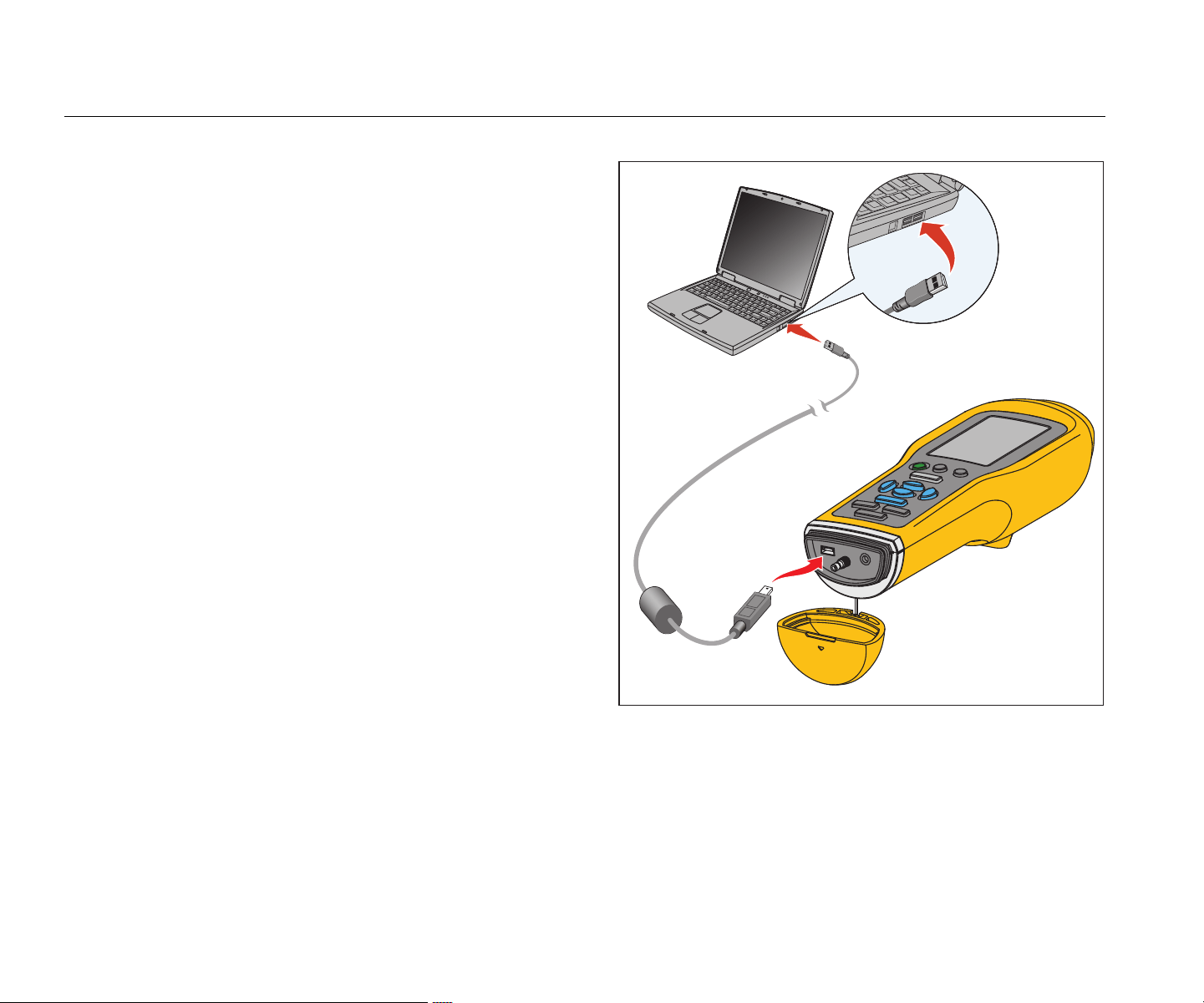
USB
Data transfer between the Meter and PC is through the
USB cable connection. The Meter turns on and stays on
when it is connected to the PC. Figure 5 shows how to
connect a PC to the Meter with a USB cable. When
connected, the Meter is a USB 2.0 mass storage device
with two functions:
• to export Meter data to an MS Excel spreadsheet (see
Export Data on page 34 for more inform
ation)
•
to upgrade the firmware (see Firmware Updates on
page 39 for more informat
ion)
gqi03.eps
Figure 5. Meter to PC Connection (805 shown)
1.888.610.7664 sales@GlobalTestSupply.com
Fluke-Direct.com

Vibration Meter
About Measurements
17
About Measurements
The Meter measures bearing health and the overall
vibration condition of a machine. Three types of
measurements are available: bearing vibration, overall
vibration, and temperature. Vibration measurement units
are user-selectable. More information about how to
change these units is on page 9.
For the best measurements, use these guidelines:
•
Pus
h and position the Meter perpendicula
r to
the test su
rfac
e.
•
Push the sensor tip onto the test surface,
on solid
metal, and as close to the beari
ng as possible until th
e
gree
n LED turns on
.
•
Hold Meter in position with a consis
tent force until the
green LED turns
off. The test results sh
ow on the
displ
a
y.
In most appli
cations the default RPM setting of >600 RPM
is correct. You must change this range for low frequency
applications where the shaft rotation is <600 RPM. A
severity scale does not show on the display when the
setting is <600 RPM. More information about how to
change the RPM setting is on page 22.
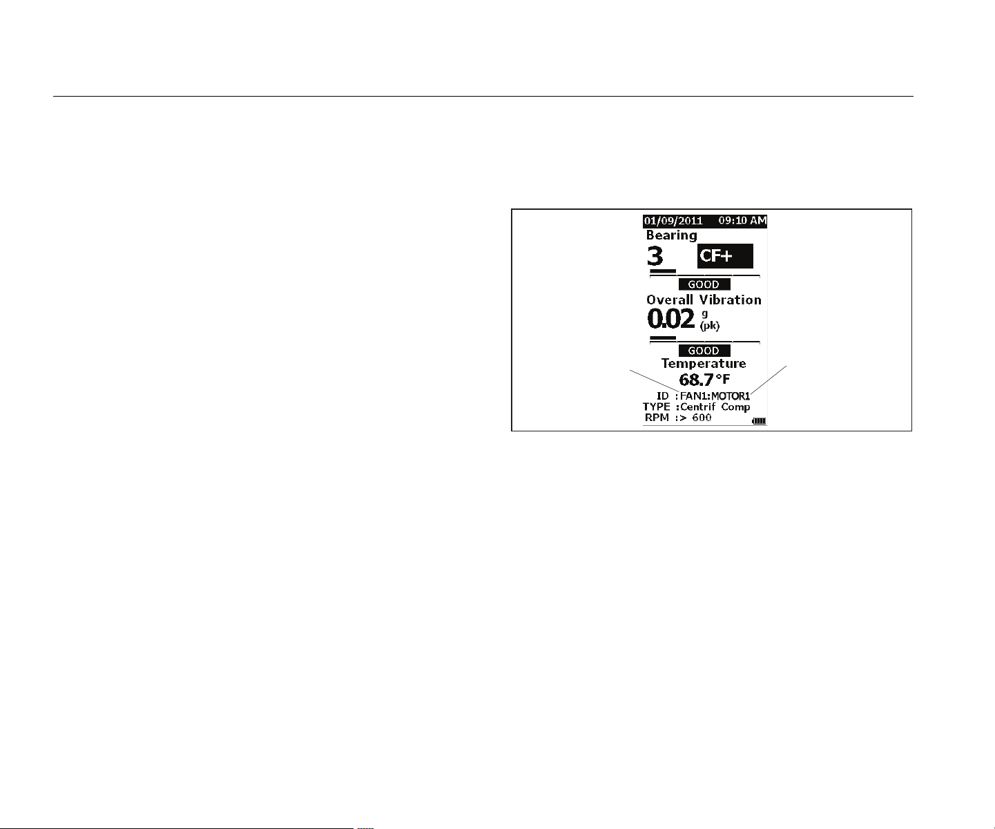
Figure 6 identifies the parts of the measurement display.
Bearing Vibration
(CF+)
High Frequency
4,000 Hz to 20,000 Hz
Overall Vibration
Frequency Range
10 Hz to 1,000 Hz
Temperature
-20
◦C to 200 ◦C
Overall Vibration
IR Temperature
gqi10.eps
Figure 6. Measurement Display
Push and to toggle the display selection between
Bearing and Overall Vibration measurements. In the
Bearing selection, push and to toggle the display units
between CF+ and acceleration. In the Overall Vibration
selection, push and to toggle the display units between
acceleration, velocity, and displacement.
1.888.610.7664 sales@GlobalTestSupply.com
Fluke-Direct.com
805/805 FC
Users Manual
18
Crest Factor+ (High Frequency Measurement)
Crest Factor is the ratio of the peak value / RMS value of a
time domain vibration signal. Vibration analysts use this
ratio to find bearing faults. However, the Crest Factor
method has a key limitation. The Crest Factor increases
during initial bearing degradation when the peak value
increases. It then decreases as the bearing damage
worsens and the RMS value increases. A low Crest Factor
value could show a healthy bearing or a significantly
degraded bearing. The problem is to know the difference
between the two.
The Meter operates with a proprietary algorithm,
Crest Factor+ (CF+), to overcome this limitation. To make
interpretation easy for the user, the CF+ value shows a
severity range. The higher the CF+ value is, the more the
bearing damage. Table 5 shows the relationship of the
values of CF+ to vibration severity.
Table 5. Crest Factor+
CF+
Sev
erity
1 to 5 Good
6 to 10 Satisfactory
11 to 15 Unsatisfactory
above 15 Unacceptable
The CF+ value shows for each measurement in the
Bearing field on the Meter display. Push and to toggle
between the CF+ value and the high frequency vibration
level in units of acceleration.
1.888.610.7664 sales@GlobalTestSupply.com
Fluke-Direct.com
Vibration Meter
About Measurements
19
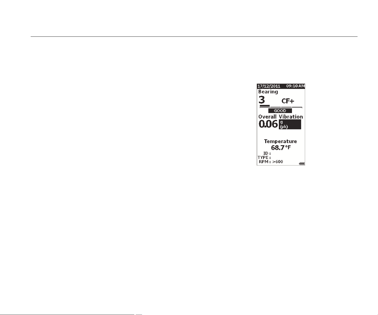
Quick Measurement
A quick measurement is a measurement without setup
steps to get a fast measurement for bearing vibration,
overall vibration, and temperature measurement.
To make a quick measurement:
1. Push to turn on the Met
er.
2.
The default screen appears without any machi
ne
ID or Mac
h
ine Category.
3. Push
.
4.
Apply compression force betwee
n the sensor tip
and test surfa
ce until the green LED turns on.
5.
Wait until the green LED turns off and sh
ows the
tes
t resu
lt.
The overall vibration a
nd te
mperature
measurement
s show on the displa
y.
gqi48.jpg
1.888.610.7664 sales@GlobalTestSupply.com
Fluke-Direct.com

805/805 FC
Users Manual
20
Overall Vibration (Low Frequency)
Measurement with Severity Scale
An overall vibration, or low frequency, measurement
includes a severity scale. The severity scale is an on-
screen tool that interprets the vibration wear as good,
satisfactory, unsatisfactory, or unacceptable. More
information about the severity scale is on page 31.
For this measurement, you must set the Meter to
recognize the type of machine, or Machine Category, for
the test. A list of the most common categories is
programmed into the Meter. When the Meter is set to a
category, it can adjust for the usual vibration levels of
different machine types. This gives you the best accuracy
in the severity scale.
After these parameters are set, the Meter shows the
overall vibration and bearing measurements with a severity
scale for each measurement. The overall vibration severity
scale uses a statistical analysis of data from thousands of
industrial machines. Keep in mind when you use the
severity scales:
• The severity scales are only applicable to machines at
speeds from 600 RPM to 10,000 RPM.
Note
Severity scales do not show if the RPM range is
<600 RPM.
• Make measurements with the accelerometer as clos
e
as po
ssible to the bearing housing.
• The severity scales are not applicable if the machine is
installed on spring or pad isolators.
• Severity scales for motors match the mach
ine that
they operate.
For example, when you do
a test on a
motor that op
erates a centrifugal pump, sele
ct the
appli
cable centrifugal pump Machine Category for all
test points on the motor and pump.
• Gearbox severity scales are applicable only for single-
stage, rolling element bearing gearboxes
.
1.888.610.7664 sales@GlobalTestSupply.com
Fluke-Direct.com

Vibration Meter
About Measurements
21
Machine Category
The Machine Category identifies the type of machine for
the test. The Meter has a list of predefined categories:
Chillers (Refrigeration)
• Reciprocating (Open Motor and Compressor Separate)
• Reciprocating (Hermetic Motor and Compressor)
• Centrifugal (Hermetic or Open Motor)
Fans
• Belt-Driven Fans 1800 to 3600 RP
M
•
Belt-Driven Fans 600 to 1799 RP
M
•
General Direct Drive Fans (Direct Coupled)
• Vacuum Blowers (Belt or Direct Dr
ive)
•
Large Forced Draft Fans (F
luid Film Brgs.)
•
Large Induced Draft Fans (Fluid F
ilm Brgs.)
•
Shaft-Mounted Integral Fan (Extended Motor Shaft)
• Axial Flow Fans (Belt or Direct Driv
e)
Cooli
ng Tower Drives
• Long, Hollow Drive Shaft (Motor)
• Belt Drive (Motor & Fan–All Arrangements)
• Direct Drive (Motor & Fan–All Arrangements)
Centrifugal Pumps
• Vertical Pumps (Height: 12 ft to 20 ft / 3.7 m to 6
m)
•
Vertical Pumps (Height: 8 ft to 12 ft / 2.4 m to 3.7
m)
•
Vertical Pumps (Height: 5 ft to 8 ft / 1.5 m to 2.4 m)
• Vertical Pumps (Height: 0 ft to 5 ft / 0 m to 1.5 m)
Note
Height is measured from grade to top motor
bearing. It may be necessary to specify lower
alarm for the lower motor bearing and the upper
pump bearing (depending on height).
• Horizontal Centrifugal Single Suction Pumps - Direct
Coupled
•
Horizontal Centrifugal Double Suction Pumps- Dire
ct
Coupled
•
Boiler Feed Pumps (Turbine or Motor Driven)
Air Compressors
•
Reciprocating
• Rotar
y Scre
w
•
Centrifugal with or without External Gearbo
x
•
Centrifugal - Internal Gear (A
xial Meas.)
•
Centrifugal - Internal Gear (Radial Meas.)
Blowers
• Lobe-Type Rotary Blowers (Belt or Direct Drive)
• Multi Stage Centrifugal Blowers (Direct Drive)
Generic Gearboxes (Rolling Element Bearings)
• Single Stage Gearbo
x
Positi
ve Displacement Pumps
• Positive Displacement Horizontal
Piston Pumps (Under
Load)
•
Positive Displacement Horizontal Gear Pumps (Und
er
Load)
Machine To
ols
•
Motor
• Gear
box Input
•
Gear
box Output
• Spindles - Roughing Oper
ations
• Spindles - Machine Finishing
•
Spindles - Critical Finishing
1.888.610.7664 sales@GlobalTestSupply.com
Fluke-Direct.com
805/805 FC
Users Manual
22
To select a Machine Category:
1. Push .
2. Push
and to highlight Machine Ca
tegory
and RPM Range
.
3. Push
to o
pen the next menu.
4. Push and to highligh
t the catego
ry.
5. Push
to
set the category.
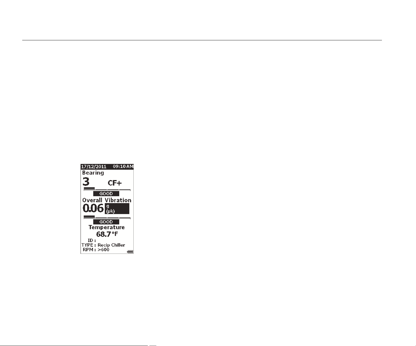
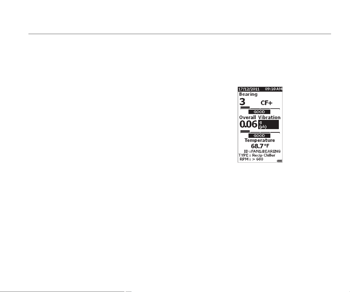
When the Machine Category is se
t, the
Measurement
screen shows the overall
vibration,
severity scale
, and the Machine Catego
ry in the
TYPE field.
gqi80.jpg
Note
The Machine Category and RPM range must be
set to view the Overall Vibration severity scale.
Create New Setup
A Setup is the group of test parameters you set for a
machine. This set of parameters includes the Machine
Category. You must set these parameters to enable the
severity scale readout. You can save these parameters in
Meter memory with a unique name, or machine ID. This is
known as a First Level ID. In each First Level ID, you can
set up multiple Second Level IDs that help to further
organize the data measurements.
The advantages when you save to a setup are:
• easy recall of a Setup for frequent measurem
ents
•
save time when the parameter selection is preset and
saved to memory
• view all measurements for a setup
• export measurements to a spreadsh
eet that tracks
machi
ne health (see Export Data on page 34 for more
information)
To make a ne
w setup:
1. Push .
2. Push
and to highlight Create NE
W Setup
.
3. Push
to o
pen the Machine Categorie
s
menu.
4. Push and to highligh
t the Machine Catego
ry.
1.888.610.7664 sales@GlobalTestSupply.com
Fluke-Direct.com
Vibration Meter
About Measurements
23
5. Push to set the category and open the
RPM Ra
nge menu.
By default, the RPM range is set to >600
RPM and
is co
rrect for most applications. To chan
ge the
RPM ran
ge: push and to highlight the
RPM
Rang
e
.
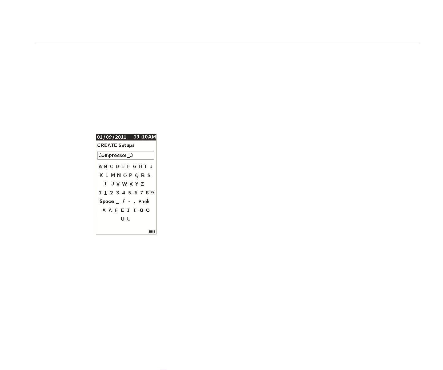
6. Push
to
set the range and op
en the
Cre
ate Setups menu for the First Level ID
.
gqi94.jpg
7. Push and to highlight a letter or number.
8. Push to
set the letter or number.
9.
Repeat steps 8 and 9 to make a unique
name for
the setup.
10. Push .
The Mete
r prompts you to give the setup a Second
Level ID. The Yes option opens the menu
to key in
a name for the ID.
11. Push
.
You can
continue this process and set up
as many
Secon
d Level IDs as necessary for the jo
b. For
example, you
can enter the bearing num
ber that
the measure
ment is taken from, such as
,
Bearin
g_1 on
FAN1.
Whe
n done, select No to go back to th
e Setup
menu. To recall a setup, see View Setups on
page 2
9
.
1.888.610.7664 sales@GlobalTestSupply.com
Fluke-Direct.com

805/805 FC
Users Manual
24
Add to Setup
You can add a Second Level ID to a setup in the Meter
memory at any time.
To add a new Second Level ID:
1. Push .
2. Push
and to highlight Add to Setup.
3. Push
and to highligh
t
the Setup name.
4. Push
to o
pen the menu for the Seco
nd
Level ID.
5. Push
and to high
light a letter or number.
6. Push to
set the letter or number.
7.
Repeat steps 5 and 6 to make a unique
name for
the setup.
8. Push .
After the Meter s
aves this new Seco
nd Level ID, it
goe
s back to the Setup me
nu.
Enable Fluke Connect (805 FC only)
You can transmit the most recent measurement with
wireless technology and view the results on the Fluke
Connect App on your device.
Note
You need to enable Fluke Connect each time you
turn on the Meter. When Fluke Connect is
enabled, a wireless icon (
) shows on the LCD.
To enable Fluke Connect:
1. Push .
2.
Use the navigation buttons to select
Enable Fluke
Conn
ect
.
To disa
ble Fluke Connect:
1. Push .
2.
Use the navigation buttons to select Disa
ble
Fluke Con
nect
.
To tran
smit a measurement to Fluke Connect:
1.
Take a measurem
ent.
2. Push
t
o open the Save screen
.
3.
Select a method to sa
ve data.
Whe
n you save, the Meter transmits the
data to
Fluke Con
nect app.
4.
Use the Fluke Connect App on your dev
ice to
receive and v
iew the test result
s.
1.888.610.7664 sales@GlobalTestSupply.com
Fluke-Direct.com

Vibration Meter
About Measurements
25
How to Save a Measurement
As you make measurements with the Meter, you can save
these measurements to memory. Quick measurements are
saved as sequential files that start at 0001. You also can
save a measurement to the current setup, an existing
setup, or give it a unique name. The Meter saves to
memory a maximum of 3,500 measurements.
Note
If the Meter exceeds the allowable memory, it
automatically deletes old records on a first in, first
out basis.
To save a measurement:
1.
Take a measurem
ent.
2. Push
t
o open the Save screen
.
Auto Save
The Auto Save option saves the measurement to memory
with a sequential number that starts at 0001. Push
to save the measurement. The Meter indicates
the record number it is saving.
Save to Existing Setup
The Save to Existing Setup option saves the measurement
to an Existing Setup.
To save the measurement to a setup:
1. Select Sav
e to: Existing Setup
.
2.
Choose the option for how to sort the machin
e IDs
or c
a
tegory.
• by
Name: shows a list of machi
ne IDs in
alpha
betical order.
• by Category: shows a list of machin
e
categ
ories in alphabetical seque
nce.
• Last Used:
shows the last machi
ne ID
measured.
3.
Highlight the machine ID.
4. Push .
1.888.610.7664 sales@GlobalTestSupply.com
Fluke-Direct.com
805/805 FC
Users Manual
26
Save to Current Setup
This option saves the measurement to the current setup in
the Meter. Push to save the measurement. The
Meter indicates the record number it is saving.
Save to New Setup
This option saves the measurement to a new setup.
To save a measurement with a new Setup name:
1. Select Sav
e to: New Setup in the Save screen.
2. Push to highlight M
achine Category
.
3. Push
to
select the opti
on.
4. Push
to highlight RPM Range S
election
.
5. Push
to
select the option to open th
e
Cre
ate Setup screen.
6.
Select the numbers and letters to enter
a new
name. See Create New Se
tup
for more
informatio
n about how to use this screen
7. Push to save the current measurement with
a new n
ame.
The Meter prompts you to give the setup a Second
Level ID.
• Selec
t Yes enter a name for the Second
Level
ID. and then
push
.
• Selec
t No to sa
ve the setup.
You can
continue this process and set up as many
Second Level IDs as necessary for the job. When
done, select No to go back to the Measurement
Results menu.
First Level ID
Second Level ID
gqi19.eps
1.888.610.7664 sales@GlobalTestSupply.com
Fluke-Direct.com
Vibration Meter
About Measurements
27
How to Recall a Setup for Measurements
You can recall a Setup file from memory for frequent
measurements done on the same machine. A Setup file
saves time when the parameter selection is already done
and stored to memory.
To recall a Setup from memory:
1. Push to open the M
EMORY scre
en.
2. Push
and to highlight Vie
w Setups
.
3. Push
to opens the VIEW SETUPS
s
creen with three sorting options
:
• by
Name: shows a list of machine setu
ps by
machi
ne ID in alphabetical sequence.
• by Category: shows a list of machin
e setups
by Machin
e Category in alphabetic
al
seq
uence.
• Last Used: shows the last used machin
e ID.
4. Push
and to highligh
t
an option.
5. Push
to o
pen the list of setups
.
6. Push
and to highligh
t
a setup.
7. Push
to o
pen the setup record.
8. Push
.
Note
Push before you apply the Meter to the test
surface.
9.
Push Meter onto test surfac
e until the green LED
turns
on.
10.
Wait until the green LED turns off.
The Measurement screen shows the sele
cted
Setup with mac
h
ine ID in the ID field.
gqi81.jpg
11. When measurement is complete, push .
12. Push
and to highlight Sa
ve
To Current
Setup.
13. Push
to
save the measurem
ent to the
setup.
To re
call a measurement, see View All Data
on
page 2
8
.
1.888.610.7664 sales@GlobalTestSupply.com
Fluke-Direct.com
805/805 FC
Users Manual
28
Access to Memory
The Memory screen contains a list of machine IDs and the
saved data. You can make changes or delete the records
from Meter memory with this screen.
Note
If the Meter exceeds the allowable memory, it
automatically deletes old records on a first in, first
out basis.
To access Meter memory:
1. Push to open the M
EMORY scre
en.
2. Push
and to highligh
t an option from
the
MEMORY screen.
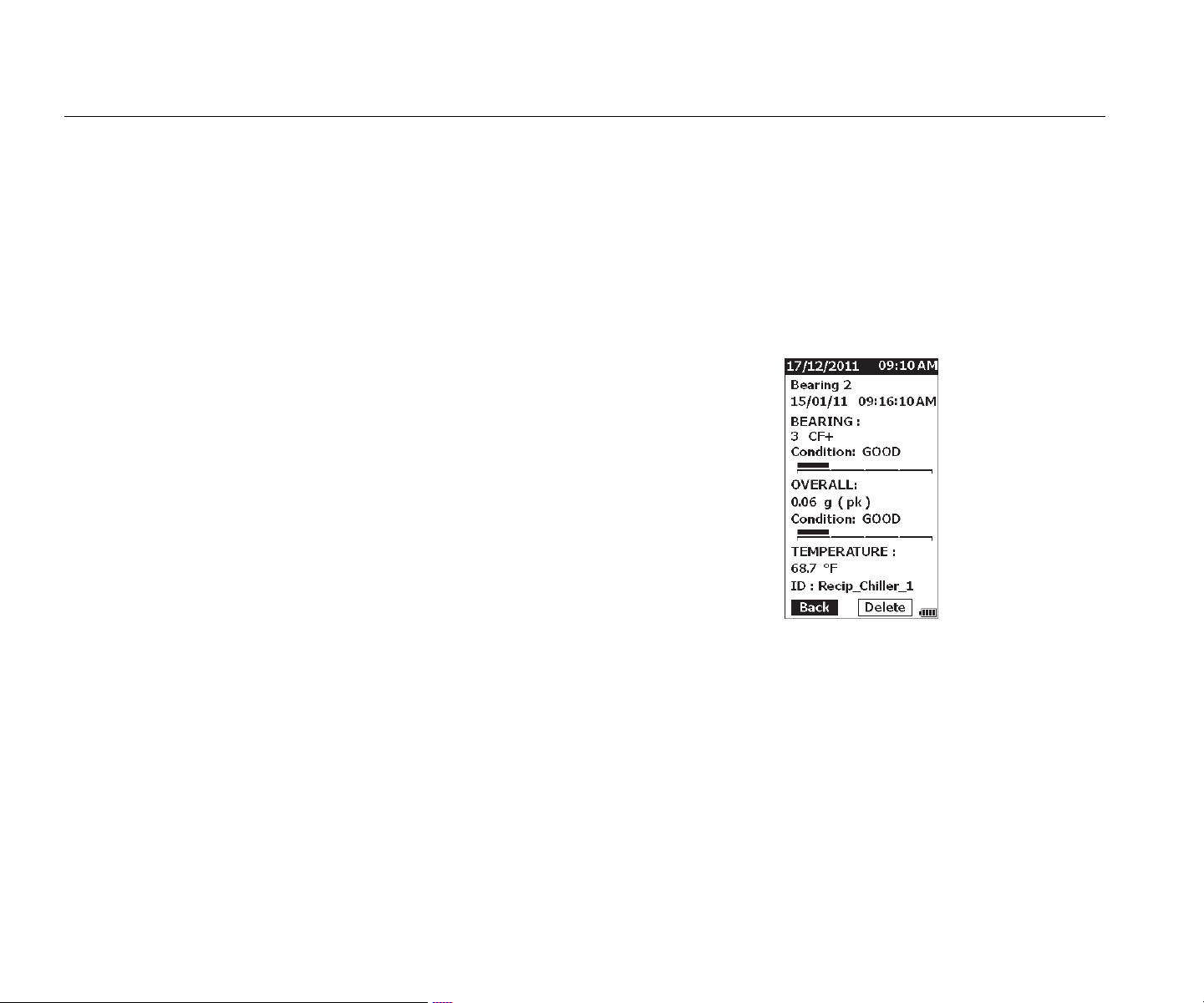
View All Data
The View ALL Data screen shows you all the
measurements saved in the Meter.
To view saved measurements:
1. Push and to highlight Vie
w ALL Data
in the
Memory screen.
2. Push
to
see more optio
ns:
• by
Name: shows a list of measurement
s by
machi
ne ID in alphabetical sequence.
• by Category: shows a list of measurem
ents
by Machin
e Categories in alphab
etical
seq
uence.
• Last Used: Shows the la
st saved
measurement.
3. Push
and to highligh
t an option from
the list.
4. Push
to
select optio
n.
5. Push
and to highligh
t
a file.
6. Push
to o
pen the file.
7. Push
to vi
ew the data.
8. Push and to s
elect Back or Delete
option.
gqi99.bmp
The Back option opens the last screen. The
Delete option removes the measurement from
Meter memory.
1.888.610.7664 sales@GlobalTestSupply.com
Fluke-Direct.com

Vibration Meter
Access to Memory
29
View Setups
The View Setups option is how you can view a setup that
is saved to memory.
To view or recall a Setup:
1. Push to open the M
EMORY scre
en.
2. Push
and to highlight Vie
w Setups
in the
Memory screen.
3. Push
. T
his opens the View Setups
screen with three sorting options:
• by Name: shows a list of machine setu
ps by
machi
ne ID in alphabetical sequence.
• by Category: shows a list of machin
e setups
by Machin
e Category in alphabetic
al
seq
uence.
• Last Used: shows the last used machin
e
setup.
4. Push and to highligh
t
an option.
5. Push
to o
pen the list of setups
.
6. Push
and to highligh
t
a setup.
7. Push
to o
pen the setup record.
8. Push and to s
elect Back or Delete
option.
The Ba
ck option opens the last scre
en. The
Delet
e option removes the setup from Me
ter
memory.
Edit Setups
Use this option to edit the Machine Setups that are saved
in Meter memory. When any change is made to a Machine
ID, all measurement data that is connected with the record
is deleted.
To edit a Machine Setup:
1. Push to open the M
EMORY scre
en.
2. Push
and to highlight Edit Setups.
3. Push
to o
pen the Sort Setups screen
.
The Sort Setups
screen is how to look
up the
saved Ma
chine Setups:
• by Name: shows a list of Machine Setu
ps by
machi
ne IDs in alphabetical sequence.
• by Category: shows a list of Machin
e Setups
by the machi
ne categories in alphab
etical
seq
uence.
• Last used: Shows the last used Machin
e
Setup.
1.888.610.7664 sales@GlobalTestSupply.com
Fluke-Direct.com

805/805 FC
Users Manual
30
4. Push and to highlight an option.
5. Push
to o
pen the Existing Setups screen.
6. Push and to highligh
t
the setup.
7. Push
to o
pen the EDIT SETUP scre
en
for the ID, TYPE, and RPM.
8. Push
and to highligh
t
the ID line.
9. Push
to o
pen the Edit Setups screen
for
the ID.
10.
Select the numbers and letters to chang
e the
machi
ne ID of the setup. See Create Ne
w Setup
for more information abo
ut how to use this screen.
11. Push t
o exit the alpha-numeric screen an
d
pick anoth
er parameter to
edit.
Clear All Data
The Clear ALL Data option lets you delete all the Machine
Setups and measurements.
To clear memory:
1. Push .
2. Push
and to highlight Clear ALL
Data
.
3. Push
.
4.
To confirm deletion, push to select Yes
.
5. Push
to delete all data.
1.888.610.7664 sales@GlobalTestSupply.com
Fluke-Direct.com
Vibration Meter
Interpret Results
31
Interpret Results
The Meter is a screening tool to identify machinery
problems for more diagnostic tests. The Meter has a
vibration severity scale for Bearing and Overall Vibration
measurements. It can also trend vibration measurements
over time. If a measurement shows high vibration severity,
or if there is an adverse trend in vibration severity over
time, then the machine can have a problem. Fluke
recommends that you consult a vibration specialist for
more tests to find the root cause of these problems.
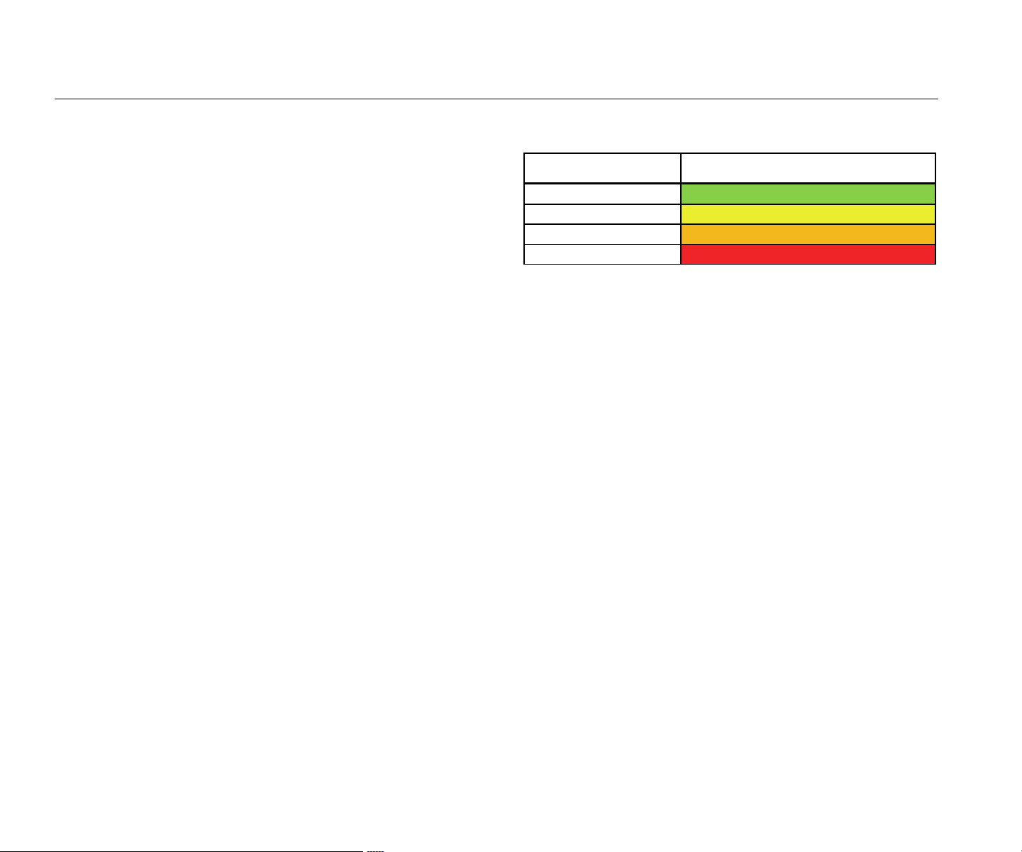
Severity Scale
Measurements with a machine ID, machine category, and
rotational speeds >600 RPM includes both severity scales.
A good measurement always finds some vibration. There
are four severity levels: good, satisfactory, unsatisfactory,
and unacceptable. A measurement in the good category is
an indication of a healthy machine.
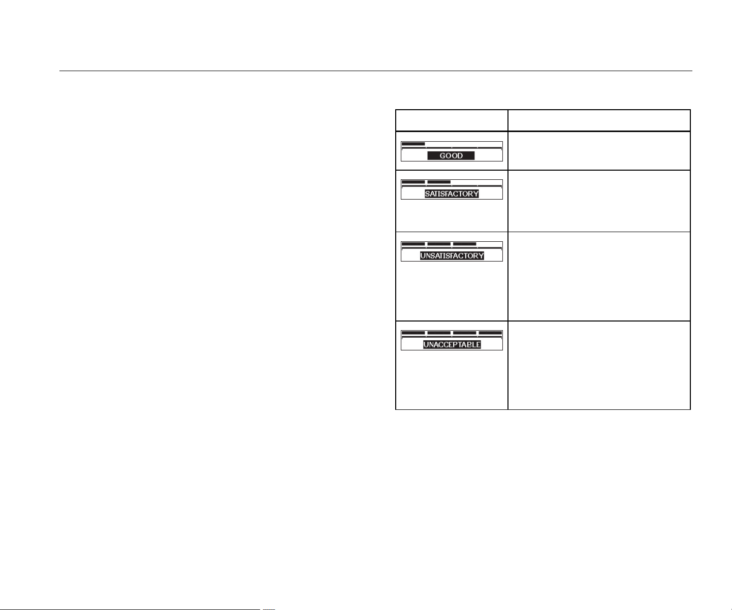
Table 6 lists the different severity scales.
Table 6. Severity Scale
Scale Actio
n
No repair action is recommended.
No immediate repair action is
required. Increase the frequency of
measurements and monitor the
condition of the machine.
Have a knowledgeable vibration
technician conduct more advanced
tests at the earliest opportunity.
Consider maintenance action at the
next planned downtime or
maintenance period.
Have a knowledgeable vibration
technician conduct more advanced
tests as soon as possible. Consider
immediate shutdown of the
machine to make repairs and
prevent failure.
1.888.610.7664 sales@GlobalTestSupply.com
Fluke-Direct.com
805/805 FC
Users Manual
32
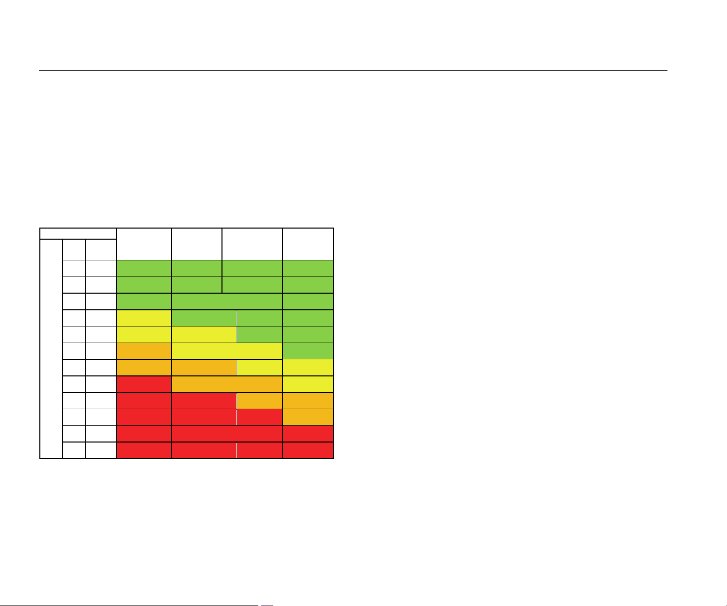
ISO 10816 Standards
As an alternative to the Overall Vibration Severity Scale
included in the Meter, you can use the ISO Standard
10816-1 to evaluate the severity of overall vibration levels.
Table 7 is a chart that contains the values from this
standard. You can compare the overall vibration value
measured with the Meter to this table to identify the
vibration severity.
Table 7. Vibration Severity - ISO 10816-1
Machine Class I
Small
Machines
Class II
Medium
Machines
Class III
Large Rigid
Foundation
Class IV
Large Soft
Foundation
Vibration Velocity Vrms
in/s mm/s
0.01 0.28
0.02 0.45
0.03 0.71 GOOD
0.04 1.12
0.07 1.80
0.11 2.80 SATISFACTORY
0.18 4.50
0.28 7.10 UNSATISFACTORY
0.44 11.20
0.70 18.00
1.10 28.00 UNACCEPTABLE
1.77 45.9
Trending
Trending, or repeated vibration measurements kept in a
spreadsheet over time, is the best method to track
machine health. See Export Data on page 34 for more
information about the template and measurement plots.
The Excel template also can give an Overall Vibration
Severity that refers to one of three ISO Standards:
•
1081
6-1
•
1081
6-3
•
1081
6-7
A brief description of each standard and terms is as
follows:
ISO 10816-1
This standard contains general guidelines for machine
vibration measurements on non-rotating parts.
Key terms
Class I: Individual parts of engines and machines
integrally connected to the machine in normal
operation. Production electrical motors at a maximum
of 15 kW are examples of machines in this category.
Class II: Medium-sized machines (typically electrical
motors with 15 kW to 75 kW output) without special
foundations, rigidly mounted engines or machines (up
to 300 kW) on special foundations.
1.888.610.7664 sales@GlobalTestSupply.com
Fluke-Direct.com

Vibration Meter
Interpret Results
33
Class III: Large prime-movers and other large
machines with rotating masses mounted on rigid and
heavy foundations that are relatively stiff in the
direction of the vibration measurements.
Class IV: Large prime-movers and other large
machines with rotating masses mounted on
foundations that are relatively soft in the direction of
vibration measurements (for example, turbo generator
sets and gas turbines with outputs greater than
10 MW).
ISO 10816-3
This standard is used to evaluate machine vibration by
measurements on non-rotating parts, for industrial
machines with nominal power above 15 kW and nominal
speeds between 120 RPM and 15,000 RPM when
measured in situ.
Key terms
Rigid: A machine foundation with the machine
supports rigidly attached to the machine skid and/or
the solid floor of the facility.
Flexible: A machine with flexible attachment between
the machine supports and foundation or facility floor.
The most common example of this is a machine in
which vibration isolators (flexible vibration damping
mechanisms) separate the machine and foundation.
Group 1: Large machines with rated power above
300 kW and not more than 50 MW (electrical
machines with shaft height: H ≥315 mm).
Group 2: Medium-sized machines with rated power
above 15 kW up to and including 300 kW, electrical
machines with shaft height 160 mm ≤ H <315 mm.
ISO 10816-7
This standard is used to evaluate machine vibration on
rotor dynamic pumps by measurements on nonrotating
parts.
Note
The standard includes guidance for
measurements on rotating shafts, but this portion
is not applicable to the Meter.
Key terms
Category I: Pumps that require a high level of
reliability, availability, or safety (for example, pumps for
toxic and hazardous liquids, critical applications, oil
and gas, special chemical, and nuclear or power plant
application).
Category II: Pumps for general or less critical
applications (for example, pumps for non-hazardous
liquids).
1.888.610.7664 sales@GlobalTestSupply.com
Fluke-Direct.com
805/805 FC
Users Manual
34
Export Data
The export data feature lets you move data from the Meter
to a PC through the USB connection. You can download a
Microsoft Excel template from www.fluke.com. You can
use the template to evaluate the measurements. The
template includes fields for:
• Device ID (the Meter from which the data wa
s
download
ed
)
•
Machine ID (the machine on which the test wa
s
perfo
rmed, machine ID may contain two
levels)
•
Machine Category (such as pump or compre
ssor)
•
High frequency/bearing measurement (Crest Fa
ctor+)
•
Low frequency reading (overall vibration)
•
T
emperatur
e
• Time
and Date
To download the Trending
template:
1.
Turn on the computer
(PC) and go to
www.fluke.co
m
.
2. Locate the Trending template and save a copy to
your PC.
To export dat
a and use the Trending template to plot a
graph:
1.
Make sure the Meter is
off.
2.
Connect the USB cable be
tween the PC and the
Meter. The M
eter turns on and stays on when
it is
con
nected to the PC. See USB on page
16 for
more info
rmat
ion.
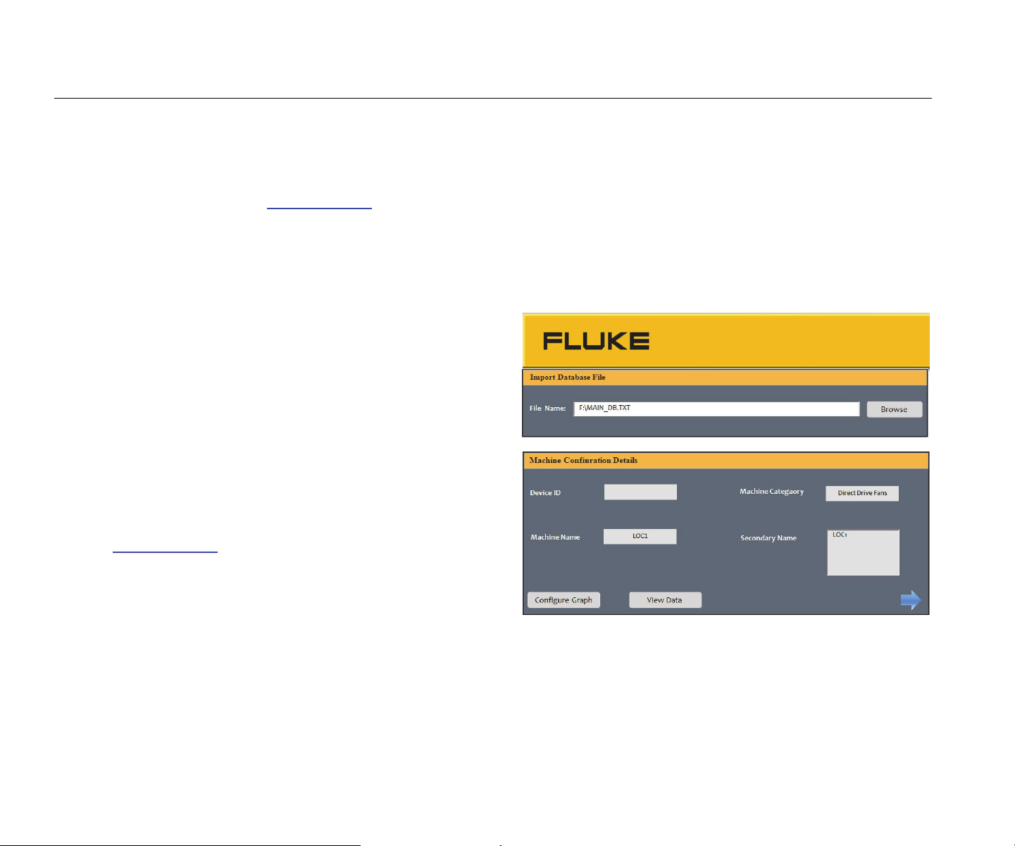
3.
Open the template on the PC. See Figure 7.
gqi203.jpg
Figure 7. Import Database
1.888.610.7664 sales@GlobalTestSupply.com
Fluke-Direct.com
Vibration Meter
Export Data
35
4. Click Browse to find the MAIN_DB.TXT data file
on the Meter.
5. Click Op
en
.
Note
The Trending template only reads data from files
in TXT file format.
The file path shows in the File name field of the
Trending template.
Note
Even though the template is password protected,
you can copy and paste the raw data from View
Data into a blank Excel spreadsheet.
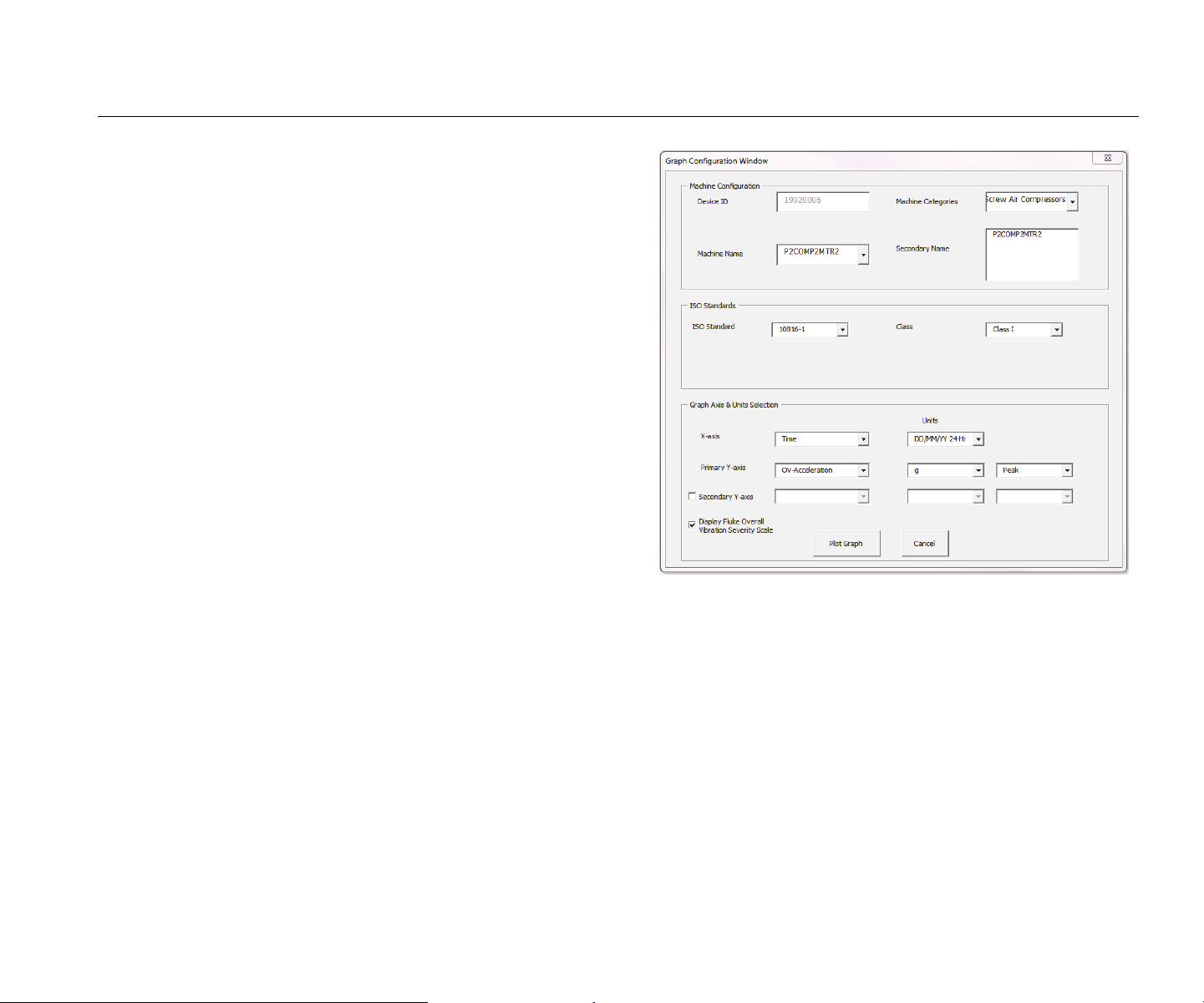
6. Click Co
nfigure Graph
on the Trending template.
The Gra
ph Configuration Window opens. See
Figure 8.
gqi205.bmp
Figure 8. Plot Options
1.888.610.7664 sales@GlobalTestSupply.com
Fluke-Direct.com
805/805 FC
Users Manual
36
7. Click each drop-down list to select the Machine
Con
figuration from the saved measurement data:
• Machine Categories
• Machine Na
me
• Select Seco
ndary
Name
8.
Click the drop-down list for the ISO Standard a
nd
cla
ss.
9.
Click each drop-down list to select the
Graph Axis
& Unit Selection for the plot:
•
X-axis required Parame
ters
•
X-axis required Unit
s
•
Y-axis required Parame
ters
•
Y-axis required Unit
s
•
Option for a secondary Y-axis (shows on
the
right sid
e of the graph)
• Option to show the Fluke
Overall Vibration
Severity Scale
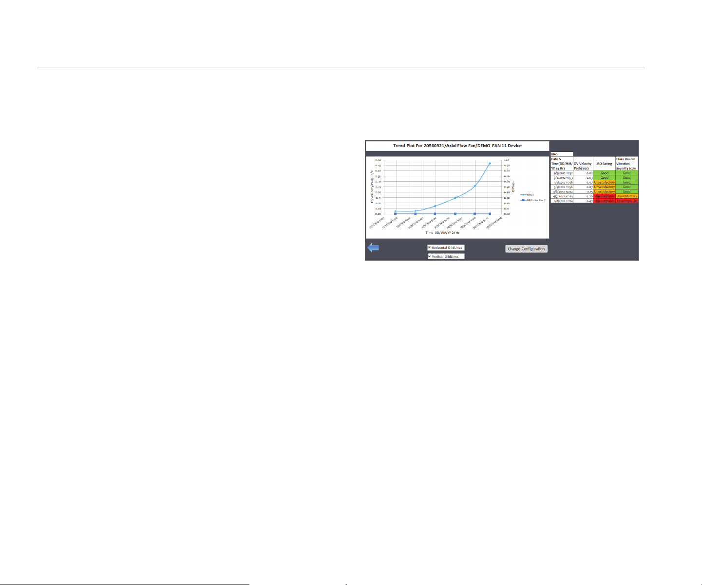
10. Click
Plot Graph.
Figure 9 is an
example of a graph you ca
n make
with mea
surement data from the Meter.
gqi206.bmp
Figure 9. Data Plot Graph
Note
You can Print the results to a local printer, press
Ctrl + P to open up the Print menu.
1.888.610.7664 sales@GlobalTestSupply.com
Fluke-Direct.com

Vibration Meter
General Maintenance
37
General Maintenance
Maintenance is not necessary for the Meter.
Caution
No part of the Meter is serviceable by the user.
Do not try to open the Meter.
Caution
To prevent damage to the Meter or any
performance loss, do not put the Meter in
temperature extremes. The ambient operating
temperature is -20 °C to 50 °C (-4 °F to 122 °F)
with a humidity of 10-95% RH
(non-condensing).
Care
Care should be taken to prevent scratches on the IR
temperature sensor window.
Caution
To prevent damage to the IR temperature
sensor and vibration sensor, do not hit, shake,
or let the Meter fall. A damaged sensor
decreases the diagnostic quality.
How to Clean
For the best accuracy of temperature measurements,
clean the IR temperature sensor window with moist cloth
before you take measurements. Clean the external case of
the Meter at regular intervals with a moist cloth and a weak
detergent solution.
Caution
To prevent damage or performance loss, keep
the Meter dry. Do not put the Meter into any
liquid. The Meter is not waterproof.
1.888.610.7664 sales@GlobalTestSupply.com
Fluke-Direct.com
805/805 FC
Users Manual
38
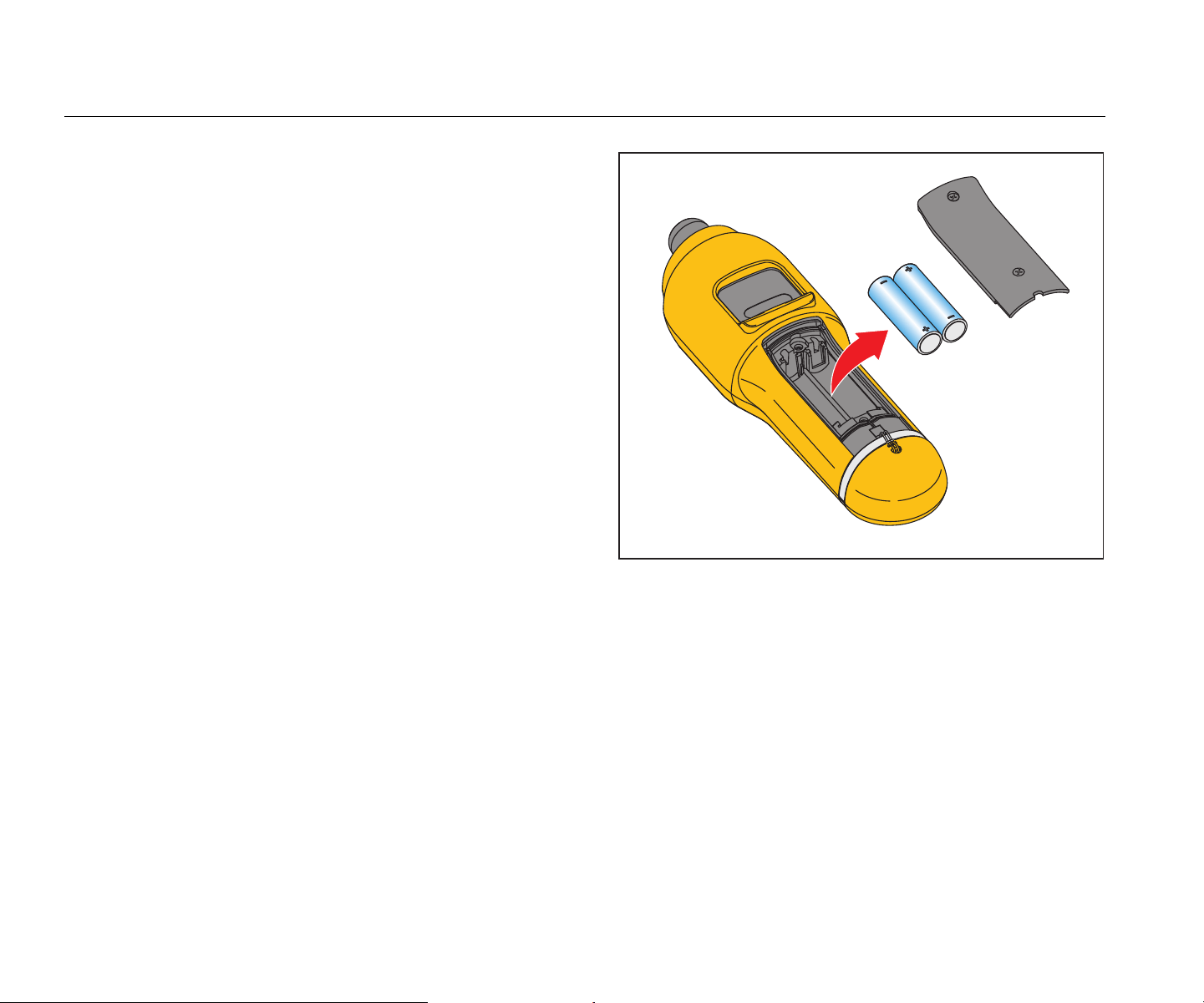
Battery Replacement
Note
Before the Meter operates for the first time, install
the new batteries included with the shipment.
The Meter operates on two AA non-rechargeable lithium
batteries.
To replace the batteries:
1.
Loosen the two screws and remove the
battery
cover from th
e Meter, see Figure 10.
2.
Align the batteries into the battery slot wi
th the
c
orrect polarity.
3.
Replace the battery cover and tighten the screws.
Note
Select the correct battery type in the Battery
Selection menu. See page 12 for more
information.
gqi02.eps
Figure 10. Battery Replacement
1.888.610.7664 sales@GlobalTestSupply.com
Fluke-Direct.com

Vibration Meter
Firmware Upgrades
39
Firmware Upgrades
At intervals, upgrades are available for the Meter firmware.
Contact Fluke for upgrade availability. If you have
registered your Meter purchase, Fluke will send an
upgrade notice to you automatically.
To upgrade the Meter:
1.
Download the upgrade file for the Mete
r from the
Fluke web
site at www.fluke.com
.
2. Connect the USB cable to the PC or laptop. See
USB on pag
e 16 for more informatio
n.
3.
Make sure the Meter is
off.
4.
Simultaneously push and hold and
as
you con
nect the other end
of the USB cable to the
Meter.
The Mete
r boots up in the firmware upgrade mode
and stays on while it is connecte
d to the PC.
5.
Identify the external disk that is the Mete
r in an
Explorer
window on the computer.
6.
Make a copy of the upgrad
e file to the external
disk that is the Meter.
7.
Right-click on the external disk and select eject.
8.
Disconnect the Meter from the host PC.
9.
Restart the Me
ter.
The Mete
r operates with the new firmwa
re after
the restart.
1.888.610.7664 sales@GlobalTestSupply.com
Fluke-Direct.com

805/805 FC
Users Manual
40
How to Troubleshoot
Table 8 is a list of problems, causes, and corrective actions for the Meter.
Table 8. Troubleshooting
Symptom
Caus
e Corrective Action
Meter does not turn on.
•
The battery voltage is too
low.
•
The battery connection is
loose.
1.
Replace the batteries. See Battery Replacement
on
page 3
8 for more informat
ion.
2.
Ensure the batteries are properly aligne
d and
secured.
3.
If the problem continues, contact the Fluke Servic
e
Cente
r
[1]
for technical support.
Buttons do not operate. Meter
does not operate.
1.
Restart the Meter.
2.
If the problem continues, contact the Fluke Servic
e
Cente
r
[1]
for technical support.
The Meter cannot connect with
the PC.
The USB cable is not
connected correctly.
Correctly connect the USB cable. See USB on page 16 for
more information.
• The USB cable is
damag
ed.
• Chec
k that USB drivers
are in
stalled in
the
PC/Laptop.
1.
Examine the USB cable for any damage.
If you find
damag
e, contact the Fluke Service Center
[1]
for a
repla
cement cabl
e.
2.
Reb
oot the PC.
PC does not see the Meter is
connected.
Reboot the PC.
Error Message: Measurement
invalid. Please hold to surface
for full duration.
The Meter was not held on
the surface for a sufficient
time or with sufficient force.
Push Meter onto test surface until green LED turns on.
Wait until the green LED turns off. See About
Measurements on page 17 for more information.
[1] See How to Contact Fluke on page 1.
1.888.610.7664 sales@GlobalTestSupply.com
Fluke-Direct.com