Loading ...
Loading ...
Loading ...
SDS2000X HD Series Digital Oscilloscope User Manual
i n t . s i g l e n t . c o m 1 2 9
CAN Trigger and Serial Decode
This section covers triggering and decoding CAN signals. Please read the following for more details:
"CAN Signal Settings", "CAN Trigger" and "CAN Serial Decode".
16.5.1 CAN Signal Settings
Connect the CAN_H and CAN_L signals to the oscilloscope set the mapping relation between
channels and signals, and then set the threshold level of each signal. The process of specifying the
source and threshold is similar to "I2C Signal Settings".
In Protocol Config menu of trigger and decode, baud rate can be set to: 5 kb/s, 10 kb/s, 20 kb/s,
50 kb/s, 100 kb/s, 125 kb/s, 250 kb/s, 500 kb/s, 800 kb/s, 1 Mb/s or Custom.
The method of copying settings is the same as I2C signal settings. See "I2C Signal Settings" for
details.
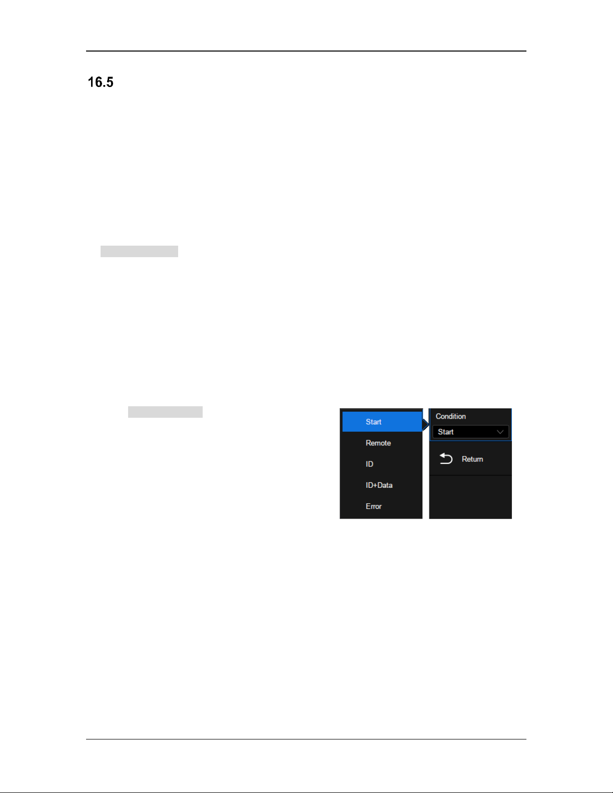
16.5.2 CAN Trigger
Touch Trigger Setting in the CAN trigger dialog
box to set the trigger condition:
Start —The oscilloscope triggers at the beginning of the frame.
Remote — The oscilloscope triggers on a remote frame with a specified ID. ID, ID Bits (11-bit or
29-bit), and Curr ID Byte (1st, 2nd, 3rd, or 4th byte) can be set. Curr ID Byte is used to specify
the byte to be adjusted when using the universal knob.
ID —The oscilloscope triggers on the data frame that matches the specified ID. ID, ID Bits (11-
bit or 29-bit), and Curr ID Byte (1st, 2nd, 3rd, or 4th byte) can be set.
ID + Data —The oscilloscope triggers on the data frame that matches the specified ID and data.ID,
ID Bits (11-bit or 29-bit), Curr ID Byte (1st, 2nd, 3rd, or 4th byte), Data1, and Data2 can be set.
Error—The oscilloscope triggers on the error frame.
Loading ...
Loading ...
Loading ...