
Loading ...
Loading ...
Loading ...
ELECTRICAL SYSTEM 16-73
Meter, Gauge, Indicator Unit
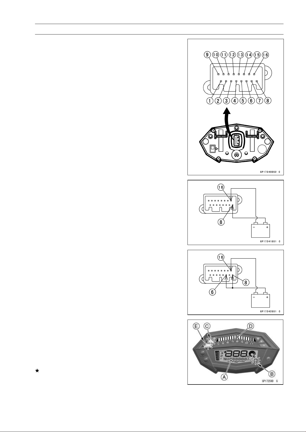
Meter Unit Inspection
•
Remove the meter unit [A] (see Meter Unit Removal).
[1] ECU Communication Line
[2] Fuel Level Sensor
[3] Green Left Turn Signal Indicator (LED) (+)
[4] Yellow ABS Indicator (LED) (–) [Equipped Models]
[5] Unused
[6] Ignition
[7] Red Warning Indicator (LED) (–)
[8] Battery (+)
[9] Blue High Beam Indicator (LED) (–)
[10] Rear Wheel Rotation Sensor Pulse
[11] Tachometer Pulse
[12] Green Neutral Indicator (LED) (–)
[13] Green Right Turn Signal Indicator (LED) (+)
[14] Unused
[15] Blue High Beam Indicator (LED) (+)
[16] Ground (–)
Check 3-1: Meter Unit Primary Operation Check
•
Using the auxiliary leads, connect the 12 V battery to the
meter unit connector as follows.
Connect the battery positive (+) terminal to the terminal
[8].
Connect the battery negative (–) terminal to the terminal
[16].
•
Connect the terminal [6] to the battery (+) terminal.
•
Check the following items.
All the LCD segments [A] appear for about 1 second.
The red warning indicator (LED) [B], yellow engine warn-
ing indicator (LED) [C] and tachometer (LED) [D] go on
for about 1 second.
The yellow ABS indicator (LED) [E] goes on (equipped
models).
If the meter unit does not work, replace the meter unit.
Loading ...
Loading ...
Loading ...