
Loading ...
Loading ...
Loading ...
FUEL SYSTEM (DFI) 3-65
Intake Air Pressure Sensor #2 (Service Code 16)
Intake Air Pressure Sensor #2 Output Voltage
Inspection
•
Measure the output voltage at the intake air pressure sen-
sor #2 in the same way as input voltage inspection, note
the following.
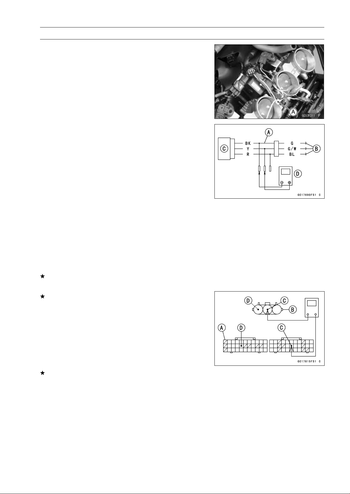
Disconnect the intake air pressure sensor #2 connector
and connect the measuring adapter [A] between these
connectors.
Main Harness [B]
Intake Air Pressure Sensor #2 [C]
Digital Meter [D]
Special Tool - Measuring Adapter: 57001-1700
Intake Air Pressure Sensor #2 Output Voltage
Connections to Adapter:
Digital Meter (+) → Y (sensor G/W) lead
Digital Meter (–) → BK (sensor G) lead
•
Measure the output voltage with the engine stopped and
with the connector joined.
•
Turn the ignition switch on.
Output Voltage
Usable Range:
DC 3.80
∼ 4.20 V at standard
atmospheric pressure (101.32 kPa, 76
cmHg absolute)
NOTE
○
The output voltage changes according to the local at-
mospheric pressure.
•
Turn the ignition switch off.
If the reading is out of the usable range, replace the sen-
sor.
If the reading is within the usable range, remove the ECU
and check the wiring for continuity between main harness
connectors.
Disconnect the ECU and sensor connectors.
Wiring Continuity Inspection
ECU Connector [A] ←→
Intake Air Pressure Sensor #2 Connector [B]
G/W lead (ECU terminal 17) [C]
G lead (ECU terminal 49) [D]
If the wiring is good, check the sensor for various vac-
uum (see Intake Air Pressure Sensor #1 Output Voltage
Inspection).
Loading ...
Loading ...
Loading ...