Loading ...
Loading ...
Loading ...
Chapter 5 To Trigger the Oscilloscope RIGOL
MSO7000/DS7000 User Guide 5-39
Trigger Type:
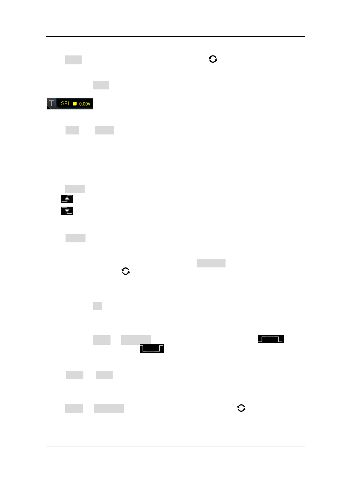
Press Type, and then rotate the multifunction knob to select "SPI". Press down
the knob to select the trigger type. Then, the current trigger setting information is
displayed at the upper-right corner of the screen, as shown in the figure below. You
can also press Type continuously to select the trigger type or enable the touch
screen to tap the desired trigger type and select it.
Source Selection:
Press CLK and MISO to specify the sources of SCL and SDA respectively. They can
be set to CH1-CH4 or D0-D15. For details, refer to descriptions in "Trigger Source".
The current trigger source is displayed at the upper-right corner of the screen.
Note: Only when we select the channel (that has been input with signals) as the
trigger source, can we obtain a stable trigger.
Edge Type:
Press Slope continuously to select the desired clock edge type.
⚫
Rising: samples the SDA data on the rising edge of the clock.
⚫ Falling: samples the SDA data on the falling edge of the clock.
Trigger Condition:
Press When continuously to select the desired trigger condition.
⚫ Timeout: the oscilloscope starts to search for the data (SDA) on which to trigger
after the clock signal (SCL) stays in the idle state for a specified period of time.
After selecting this condition, you can press Timeout, then rotate the
multifunction knob
or use the pop-up numeric keypad to set the idle time.
The range is from 8 ns to 10 s.
⚫ With CS: if the CS signal is valid, the oscilloscope will trigger when the data (SDA)
satisfying the trigger conditions is found.
➢ Press CS to select the chip selection signal line. The available channels are
CH1-CH4 or D0-D15. For details, refer to descriptions in "Trigger Source".
The current trigger source is displayed at the upper-right corner of the
screen.
➢ Press More → CS Mode to set the current CS mode to "Pos " (high
level is valid) or "Neg
" (low level is valid).
Current Bit:
Press More → Bit X to set the data bit that needs to be operated on. For setting
methods, refer to descriptions in "I2C Trigger (Option)".
Data Bits:
Press More → DataBits, then rotate the multifunction knob or use the pop-up
numeric keypad to set the number of bits in the serial data string. The number of bits
in the string can be set to any integer ranging from 4 and 32.
Loading ...
Loading ...
Loading ...