Loading ...
Loading ...
Loading ...
7
2.2.1 Functional Description
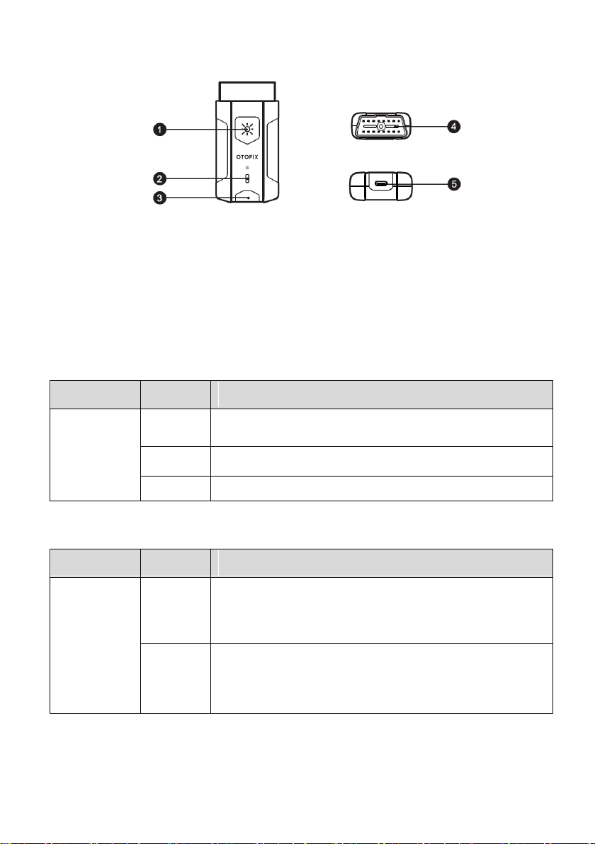
Figure 2-4 VCI Device
1. Lighting Push Button
2. Power LED — refer to Table 2–3 Power LED Description for details
3. Vehicle/Connection LED — refer to Table 2–4 Vehicle LED Description for details
4. Vehicle Data Connector (16-pin)
5. USB Port
Table 2–3 Power LED Description
LED
Color
Description
Power
Yellow
Lights solid yellow when the VCI is powered on and
performing self-check.
Green
Lights solid green when the VCI is ready for use.
Red
Flashes red when the firmware is upgrading.
Table 2–4 Vehicle LED Description
LED
Color
Description
Vehicle /
Connection
Green
Lights solid green when VCI is connected via USB
cable.
Flashes green when VCI is communicating via USB
cable.
Blue
Lights solid blue when VCI is connected via
Bluetooth.
Flashes blue when VCI is communicating via
Bluetooth.
Loading ...
Loading ...
Loading ...