Loading ...
Loading ...
Loading ...
63
TRANSCEND RAILING
NOTE: Construction methods are always improving. Please refer to www.trex.com for the most up-to-date installation requirements.
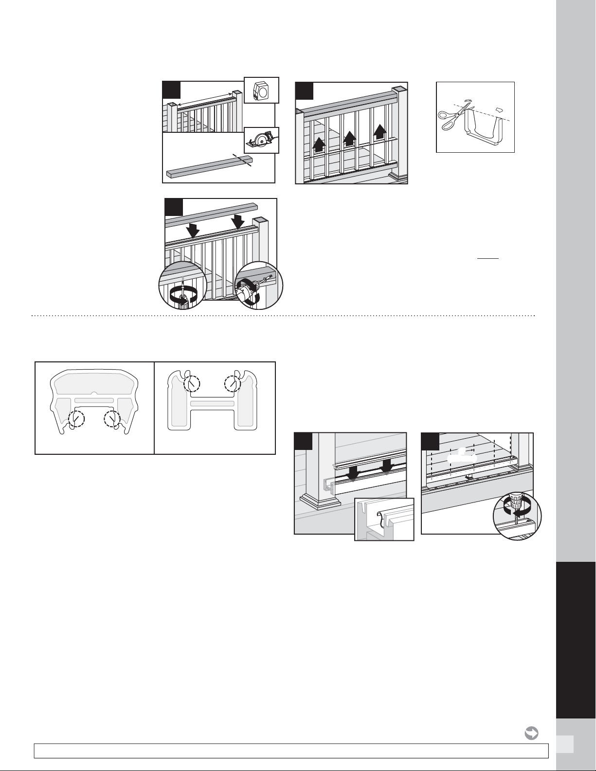
10. Measure between posts
and cut 2" x 4" (51 mm x
102 mm) to length. Place
2" x 4" (51 mm x 102 mm)
on universal rail. Attach
board to rail with 2" (51
mm) pan-head screws
(not provided) every 16"
(406 mm) on center.
11. Pre-drill a pilot hole and
toenail 2-1/2" (64 mm)
composite decking
screw (not provided) at
each end of 2" x 4"
(51 mm x 102 mm)
into post on back side
of rail (side not facing
decking).
12. Slide baluster spacer up and snap into universal rail.
NOTE: If necessary, cut tips off rail gaskets prior to
installation.
13.
Attaching Post Caps and Installing New Foot
Block
See instructions on page 61.
10
1
HOW TO INSTALL TRADITIONAL RAILING/CONTINUED
TREX TRANSCEND
1
1
11
3
2
12
Optional
HOW TO INSTALL ROUND OR SQUARE ALUMINUM BALUSTERS
TREX TRANSCEND
NOTE: Older style Crown and Universal Rails have
"fl ippers" on the inside of the channels. Using EXTREME
CAUTION, remove/cut these fl ippers on each side to
allow for the fi t of the aluminum baluster adaptor strip.
1. Installing Pressure-Treated Posts
See instructions on page 59.
2.
Installing Post Sleeve Skirts and Post Sleeves
See instructions on page 59.
3.
Installing Railing Support Brackets (RSBs)
See instructions on page 59.
4.
Cutting Railings
See instructions on page 60.
5.
Attaching Foot Block
See instructions on page 60.
6.
Attaching Bottom Rail (Universal Rail)
See instructions on page 60.
Installing Aluminum Baluster Adaptor Strip,
Adding Weep Holes, and Baluster Spacers
7. After bottom rail is fully installed, place aluminum
baluster adaptor strip into channel of bottom rail,
ensuring that it’s fully seated into the channel. When
rail lengths are non-standard, the baluster adaptor
strip will need to be cut 2-1/2" (64 mm) shorter than
the rail to allow clearance for the RSB’s on each end.
7a. Center and drill 5/16" (8 mm) weep holes through
bottom rail channel and adaptor strip to allow for
water drainage. Holes should be placed between fi rst
two balusters on each side and approx. 2' (610 mm)
spans along length of rail.
Crown Rail
with “flippers”
Universal Rail
with “flippers”
7
7a
2
'
(610 mm)
2'
(610 mm)
Loading ...
Loading ...
Loading ...