2017 INSTALLATION GUIDE
TREX
®
DECKING
AND RAILING
ENGLISH

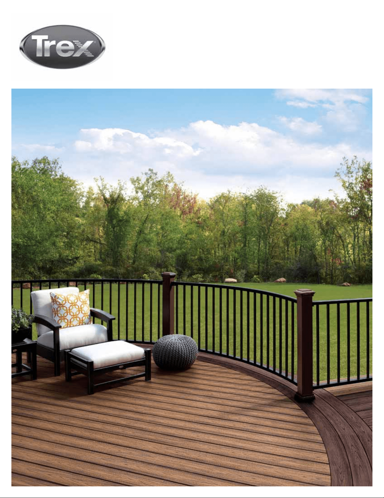
ON THE COVER
decking:
Transcend in Tiki Torch & Lava Rock
railing: Signature in Charcoal Black
with Trex posts in Vintage Lantern
» Page 5 – Removed Trex Hideaway Universal Collated Clip System
» Page 7 – Renamed Reveal Railing Care and Cleaning Guide to Signature Railing Care and Cleaning Guide
» Page 8 – Removed Glossary of Terms page
» Page
12 – Added SKU page for Trex Lighting products
» Page
21 – Renamed Trex Reveal Post Cap Light to Signature Post Cap Light
» Page
23 – Renamed Trex Reveal Post Lamp to Trex Wedge Deck Rail Light
» Page
26 – Added SKU page for Decking and Hidden Fasteners
» Page
33 – Updated stair overhang from ½” to ¾”
» Page
35 – Added tip about using additional fastening method when using Trex Universal Fasteners in wide
temperature range environments
» Page
40 – Updated Surface Mount Post Instructions to show revised picture of guide block
» Page
44 – Updated Joist Mount Post Instructions to clarify attachment methods and show revised picture
of guide block
» Page
53 – Added SKU for Transcend, Signature (formally Reveal), and Select Railings
» Page
57 – Updated Transcend Railing instructions to show the following:
• Remove Colonial Baluster option
• Added post choices
• Added new footblock instructions
• Added new 3-hole bracket instructions
• Added additional details to Transcend Stair instructions
» Page
73 – Updated Reveal Railing instructions to show the following:
• Renamed to Signature Railing
• Added Signature Cocktail design
• Added Signature Traditional design
• Added Signature Stair Cocktail design
• Added Signature Stair Traditional design
» Page
107 – Renamed Reveal Panel to Signature Panel instructions
» Page
114 – Updated Select Railing instructions to show the following:
• Remove all square balusters
• Added new bracket design
» Page
129 – Updated warranties
This symbol indicates text continues to next page.
Trex provides a variety of valuable resources to answer your questions or concerns. For
additional assistance, check out:
»
Trex.com
Here you will fi nd a wealth of useful information on Trex’s extensive products including:
installation, care and cleaning instructions and videos, technical help, and FAQs. You’ll also
fi nd inspiring photos of deck projects, steps to help you plan and start your project, and
tips for selecting the right deck builder. At trex.com, you can request information, register
your warranty, and reach out to customer service representatives who can answer even
more questions.
» Call 1-800-BUY-TREX (1-800-289-8739) and speak to a technical support representative
who can answer your questions.
» Email your question or concern to question@trex.com and we’ll get back to you quickly.
Refer to www.trex.com for up-to-date installation and technical documents that may not be
found in this printed guide.
NEED HELP?
CHANGES FOR 2017 INSTALL GUIDE:
NOTE: Construction methods are always improving. Please refer to www.trex.com for the most up-to-date installation requirements.

3
INSTALLATION GUIDE
TREX INSTALLATION GUIDE
CONTENTS
SECTION ONE: General Information
Safety ......................................................................................5
Tools ........................................................................................5
Care and Cleaning ..................................................................6
SECTION TWO: Planning Ahead
Trex Decking ...........................................................................9
Railing (Including ADA Handrail) ..........................................9
Trex Lighting ...........................................................................9
Trex
®
RainEscape
®
Drainage System ...................................9
Installing Hot Tubs, Planters, and Seating ...........................9
Installing Fireplaces and/or Fire Pits ...................................9
Installing a Pergola ...............................................................10
Installing Trex
®
Spiral Stairs™ .............................................10
Installing Trex
®
Outdoor Kitchens™ ...................................10
Special Patterns ...................................................................10
SECTION THREE: Lighting
How to Install Trex
®
DeckLighting
™
Outdoor Lighting SKUs ......................................................12
Parts List/Tools Needed ................................................... 13
Lighting and Wiring Overview ..........................................13
Helpful Tips ....................................................................... 13
General Information ......................................................... 14
Pla nning ............................................................................. 14
Installing Wiring ................................................................14
Making Connections ........................................................ 14
Timer Operation Instructions .......................................... 15
Installing Post Cap Lights ................................................ 15
Installing Deck Rail Lights ................................................ 15
Installing Riser Lights .......................................................16
Installing Recessed Deck Lights .....................................16
How to Install Trex
®
LandscapeLighting
™
Parts List/Tools Needed ................................................... 17
Helpful Tips ........................................................................ 17
How to Install Trex Well Light, Path Lights, and
Multifunction Lights ..................................................... 18
How to Install Trex Spotlight ............................................ 19
How to Program Dimmer Remote.................................. 20
How to Install Signature
®
Post Cap Light
Parts List/Tools Needed ................................................... 21
Helpful Tips ........................................................................ 21
Installing Post Cap Lights ................................................ 21
How to Install Trex Wedge Deck Rail Light
Parts List/Tools Needed .................................................. 23
Helpful Tips ....................................................................... 23
Installing Post Lamps ...................................................... 23
SECTION FOUR: Decking
Decking, Porch Flooring & Fascia SKUs ............................ 26
Decking and Fascia Recommended Fasteners .................27
Trex
®
Fascia Installation Recommendations .................... 28
Framing and Fastening Tips ............................................... 28
Rooftop and Sleeper Deck Systems .................................. 30
Code Compliance ................................................................. 31
Gapping and Overhang ....................................................... 32
Stairs .................................................................................... 33
How to Install Decking
Tips for Installing a Trex Hideaway
®
Hidden Fastening
System (Stainless Steel or Universal) .............................. 34
Installing Angled Deck Boards in Corners .................... 34
How to Butt Seams.......................................................... 34 .
Routing Square Edged Boards ....................................... 34
How to Install Trex Hideaway Universal Hidden Fasteners
Parts List/Tools Needed ................................................ 35
Installing Start Clips and First Board............................. 35
Installing Universal Fasteners ........................................ 35
Installing Second Board .................................................. 35
Complete Installation ...................................................... 35
Installing Last Board
Option 1: Using Fascia Board ...................................... 35
Option 2: With Deck Board Overhang ........................ 36
Option 3: Face Screwing both Decking and Fascia ... 36
How to Install Trex Escapes
®
Boards with Trex
Hideaway Universal Fasteners ........................................ 36
How to Replace Trex Boards Installed with Trex
Hideaway Universal Fasteners ....................................... 36
How to Install Stair Treads ..................................................37
Option 1: Face Screw ........................................................37
Option 2: Using 2x4 Wood Support Blocks ....................37
How to Install Trex Transcend
®
Porch Floorboards
Parts List/Tools Needed ................................................ 38
Installing Start Clips and First Porch Board ................. 38
Installing Trex Hideaway Universal Hidden Fasteners . 38
Installing Second Porch Board ....................................... 38
Installing Last Porch Board ............................................ 39
Option 1: Using Fascia Board ...................................... 39
Option 2: With Porch Board Overhang ...................... 39
How to Install Porch Stair Treads ...................................... 39
Option 1: Hidden Fasteners and Face Screwing ........... 39
Option 2: Hidden Fasteners and 2x4 Foot Blocks ........ 39
Location and Installation of Surface Mount
Post – Decking ................................................................. 40
Parts List/Tools and Materials Needed ........................ 40
How to Install Post Mounts on Pressure-Treated
Wood Framing .............................................................. 40
Corner Post Installation .......................................... 40
Line Post Installation ................................................ 41
How to Install Guide Blocks ............................................. 41
How to Install Railing System of Choice ........................ 42
Location and Installation of Post Mounts – Concrete ..... 42
Parts List/Tools Needed ................................................ 42
Pre-drill Holes .................................................................. 42
How to Install Guide Blocks ............................................ 43
How to Install Railing System of Choice ........................ 43
How to Install Joist Mount Posts
Parts List/Tools Needed ................................................ 44
Inside Mount
Front Rim Plate – Between Joists .............................. 45
Front Rim Plate – Next to Joist ................................... 45
Side Joist ...................................................................... 46
Joist Mount Post – Inside Mount/
Continued

4
INSTALLATION GUIDE
4
4
NOTE: Construction methods are always improving. Please refer to www.trex.com for the most up-to-date installation requirements.
TREX INSTALLATION GUIDE
CONTENTS/CONTINUED
Corner ............................................................................47
Fascia Mount
Front Rim Plate – Next to Joist ................................... 48
Side Joist – With Blocking .......................................... 49
Outside Frame Corner ................................................. 50
Composite Post Applications
Installation of Guide Blocks and Railing ..................... 51
SECTION FIVE: Railing
Post Sleeves, Caps and Skirts SKUs ............................. 53
Signature Post Sleeves, Caps and Skits SKUs ............. 53
Signature Aluminum Railing SKUs ................................. 54
Transcend Railing SKUs .................................................. 55
Select Railing SKUs ......................................................... 56
Aluminum Gates SKUs .................................................... 56
Aluminum ADA Compliant Handrail SKUs .................... 56
Trex Transcend
®
Railing
Parts List/Determining Balusters Needed ....................57
Trex Transcend Railing Confi gurations
......................... 58
How to Install Standard Railing ...................................... 59
How to Install Cocktail Railing .........................................61
How to Install Traditional Railing .................................... 62
How to Install Round or Square Aluminum
Balusters ....................................................................... 63
How to Install Standard Glass Panel Railing ................. 64
How to Install Cocktail Style Glass Panel Railing ......... 66
How to Install Traditional Style Glass Panel Railing ......67
How to Install On-An-Angle Railing ................................ 69
How to Install Crown and Universal Bird’s
Mouth Railing ............................................................... 69
How to Install Crown and Universal Stair Railing ......... 70
Trex Signature
®
(formerly Reveal
®
) Railing
Parts List/Determining Balusters Needed ....................73
Installing Signature Posts and/or Signature
Crossover Posts on Decking or Concrete ..................74
Installing Pressure-Treated Post, Post Sleeves,
and Skirts to Use with Reveal Railing ......................74
Installing Signature Posts on Concrete
...................... 75
Railing Confi gurations ......................................................76
Bracket Hardware – Horizontal Applications
................77
How to Install Horizontal Railing .....................................78
How to Install Horizontal Swivel Brackets..................... 84
How to Install Horizontal Swivel Railing ........................ 85
How to Install Signature Cocktail Railing .......................87
How to Install Signature Traditional Railing .................. 88
How to Install Foot Blocks – Horizontal Railing ............ 89
Bracket Hardware – Stair Applications
........................ 90
How to Install Signature Stair Posts and Stair Railing . 92
Attaching Stair Brackets (Fixed Stair, Stair Swivel,
and Compound Swivel) to Signature Posts and
Pressure-Treated Posts and Post Sleeves ................ 93
How To Install Signature Cocktail Stair Railing ........... 101
How To Install Signature Traditional Stair Railing .......103
How to Install Aluminum Gate .......................................105
Trex Signature Panels
Parts List/Tools Needed ...............................................107
Bracket Hardware – Horizontal Applications ..............108
How to Install Panels
...................................................... 110
How to Install Foot Blocks ............................................. 113
Trex Select
®
Railing
Parts List/Determining Balusters Needed .................. 114
Select Railing Confi gurations ........................................ 115
How to Install Trex Select Railing
.................................. 115
How to Install Cocktail Railing ....................................... 118
How to Install Traditional Railing ................................... 119
How to Install On-Angle-Railing ....................................120
How to Install Trex Select Stair Railing ......................... 121
Trex Aluminum ADA Compliant Handrail
ADA Handrail Guidelines ................................................124
ADA Railing Profi les ........................................................125
How to Install Trex Aluminum ADA Compliant
Handrail .......................................................................126
90º Wall Return ...........................................................126
Wall Mount ...................................................................126
Rail-to-Rail Connections/Internal Connector ..........126
Elbows (90º, 36º, 34º, 31º, 5º) ...................................127
Handrail Return 180º ..................................................127
Corner Mount ..............................................................127
SECTION SIX: Warranties
Trex Transcend
®
, Trex Enhance
®
, Trex Select
®
, and Trex
®
Universal Fascia Limited Fade & Stain Warranty ................ 129
Trex
®
Limited Warranty ....................................................... 131
Trex Signature
®
/Reveal
®
Railing Limited Warranty ........132
Color Palette ..............................................Inside Back Cover
5
GENERAL INFORMATION
SAFETY
When working on any construction project, you should
wear protective clothing and safety equipment. Wear
safety glasses, gloves, a dust mask and long sleeves,
particularly when cutting in confi ned spaces.
Trex decking and railing are heavier and more fl exible
than wood. DO NOT try to lift the same quantity of
Trex boards as you would traditional lumber. Go to
www.trex.com for Safety Data Sheets (SDS).
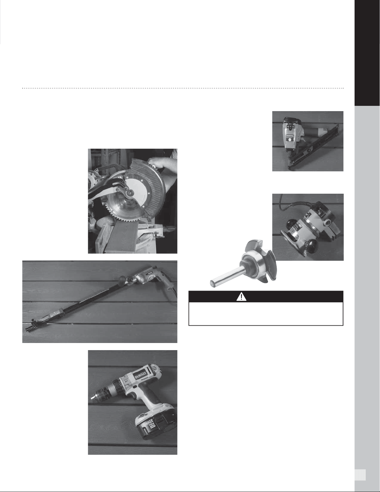
TOOLS
You can create intricate shapes, profi les, and patterns
with Trex. Most installments require no special tools.
For best results, use carbide-tipped blades and router
bits.
When using a miter
saw, we recommend
using the Trex
Blade
™
*. This
comes in 3 different
sizes and is ideal
for cutting all our
decking and railing
products (these are
not recommended
for cutting Trex
Elevations
®
). Refer
to www.trex.com for
more information.
Install Trex
recommended
fasteners with
standard power drills
or approved screw
guns.
If your choice is to use
the metal Trex Hideaway
Hidden Fasteners, using
the pneumatic gun by
TigerClaw
®
* is a terrifi c
option. This will allow for
a quicker install time.
Trex Gun Pail includes
900-count connector clips
and TC-SG collated pneumatic screws.
Trex
routs beautifully to
give extremely crisp edges.
The groove cutter/router
bit is used with the Trex
Hideaway fastening
system.
CAUTION
DO NOT rout balusters. Routing will change the
surface of Trex products.
*Tiger Claw® is a registered trademark of Tiger Claw, Inc.
* Trex Blade
™
is manufactured and sold by Freud Tools, Inc. under a
Trademark License Agreement with Trex Company, Inc.
6
GENERAL INFORMATION
NOTE: Construction methods are always improving. Please refer to www.trex.com for the most up-to-date installation requirements.
TREX TRANSCEND
®
, TREX ENHANCE
®
, AND TREX SELECT
®
CARE AND
CLEANING GUIDE
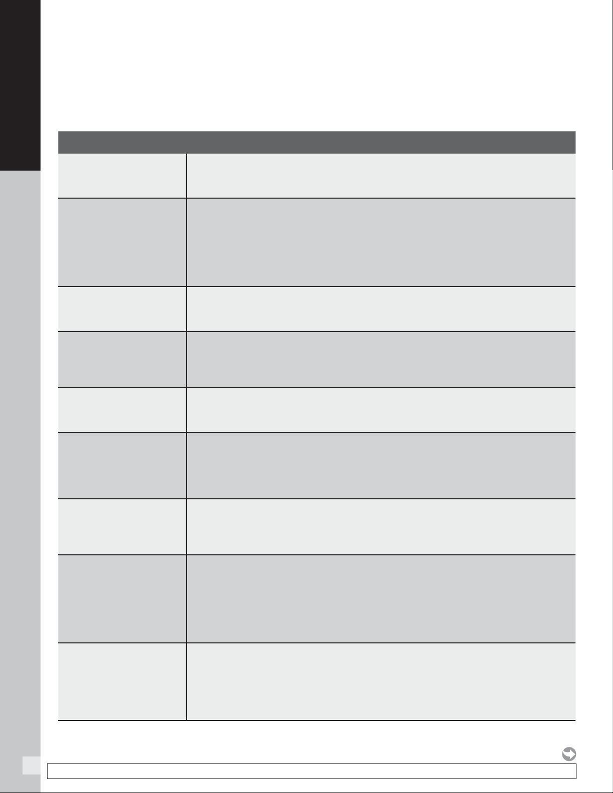
All exterior building materials require cleaning. Generally, soap and water is all that is required to clean Transcend,
Enhance, and Select products. For further information, see below.
PROBLEM SOLUTION
Dirt and Debris
The affected area should be sprayed off with a hose to remove surface debris. Use warm
soapy water and a soft bristle brush to remove dirt and debris from the embossing pattern.
Hard Water Staining
Hard water is water with a high amount of mineral deposits like lime, silica and calcium.
When the water dries, deposits are left behind, leaving unsightly spots on surfaces. This
is not a defect of Trex products but an issue with the water itself. Generally these deposits
can be cleaned with white vinegar on decking surfaces or use of Magic Eraser
®
on railing
surfaces. Rinsing is required so care should be taken to not use hard water for this purpose,
and if it must be used, dry with a cloth or use a blower to dry surfaces.
Chalk Lines
Most colored chalks are permanent and may discolor the surface. Use only Irwin Strait-
Line
®
* Dust-Off Marking Chalk (purple), available at Irwin.com
Tannins Due to Debris
Remove all debris from the deck using a hose or broom. Once the deck surface is dry,
apply a deck “brightener”** to the deck as directed by the manufacturer. Deck Brighteners
contain oxalic acid, which will also remove tannins.
Ice and Snow
A plastic shovel may be used to remove snow from the deck. Use calcium chloride or rock
salt to melt the snow and ice from the deck surface.
Oil, Grease, and Food
All food spills should be removed as soon as possible. The surface must be cleaned
within seven days to maintain the stain warranty. To remove, spray off with a hose
and use warm, soapy water and a soft bristle brush to remove spills from the embossing
pattern.
Mold and Mildew
If debris such as pollen and dirt is allowed to remain on the deck surface, mold can feed on
the biofilm. Using a hose and warm, soapy water with a soft bristle brush is recommended
to remove the food source and mold.
Using a Pressure
Washer (Concrete,
Stucco, or Ground-in
Construction Dirt)
A pressure washer with no greater than 3100 psi*** that has a fan attachment/
adjustment and soap dispenser may be used to remove dirt, concrete dust, or other types
of construction dirt. Spray deck with soap, then follow by gently scrubbing each deck board
with a soft bristle brush. Spray/rinse each individual deck board using a fan tip no closer
than 8-in (203 mm) from the decking surface. RINSE THOROUGHLY. If dirty water from
cleaning is left to dry, this will cause a film to remain on the decking surface.
Maintaining
Transcend and
Select Railing
NEVER use acetone or other solvents on Trex Transcend or Select railing to maintain the
beauty of the surface. For color transfer issues (from attachment of baluster spacer), use
Mr. Clean
®
Magic Eraser
®
Original or Magic Eraser
®
Extra Power**** to help remove this.
For small surface scratches, marks, or scuffs, use Dupli-Color Scratch Seal
™
Clear Sealer
Pen.*****
7
GENERAL INFORMATION
7
TREX SIGNATURE
®
RAILING CARE AND CLEANING GUIDE
Maintaining the appearance of your Trex Signature railing is important. The occasional wash is recommended
as over time your Signature railing may show signs of weathering as a result of exposure to the elements. The
frequency of cleaning will depend on the environment and exposure to various types of elements.
For installations where the atmosphere is infl uenced by bodies of salt water or other contaminant
conditions, cleaning is required every 6 to 9 months. Failure to adhere to the required cleaning guidelines
will void the Trex Limited Warranty with respect to any condition resulting from such failure. For purposes
of any warranty claim, you should retain documentation of the cleaning date, cleaning method used, brand
and amount of chemical used, and invoice from cleaning company (or a receipt for chemicals used).
Regular cleaning may minimize the effects of weathering and remove dirt, grime and other build-up. The best
method of maintaining the appearance of your Signature railing is to occasionally wash it using a solution of warm
water and a non-abrasive, pH neutral detergent solution. The railing surface should be thoroughly rinsed after
cleaning to remove all residues. Use a soft white cloth, sponge or a soft bristle brush.
DO NOT clean Trex Signature railing with solvents such as thinners or solutions containing chlorinated
hydrocarbons, esters or ketones.
The following cleaners are recommended for cleaning Trex Signature railing:
» Formula 409
®
Cleaner Degreaser/Disinfectant*
» Spray Nine
®
Cleaner/Disinfectant**
» Simple Green
®
All Purpose Cleaner***
» Fantastik
®
All Purpose Cleaner****
» Windex
®
Cleaner*****
* Formula 409® Cleaner Degreaser/Disinfectant is a trademark of Clorox Company.
** Spray Nine® All Purpose Cleaner/Disinfectant is a trademark of Illinois Tool Works Inc.
*** Simple Green® All Purpose Cleaner is a trademark of Sunshine Makers Inc.
**** Fantastik® All Purpose Cleaner is a trademark of SC Johnson & Son Inc.
***** Windex® is a trademark of SC Johnson & Son Inc.
TREX TRANSCEND
®
, TREX ENHANCE
®
, AND TREX SELECT
®
CARE AND
CLEANING GUIDE/CONTINUED
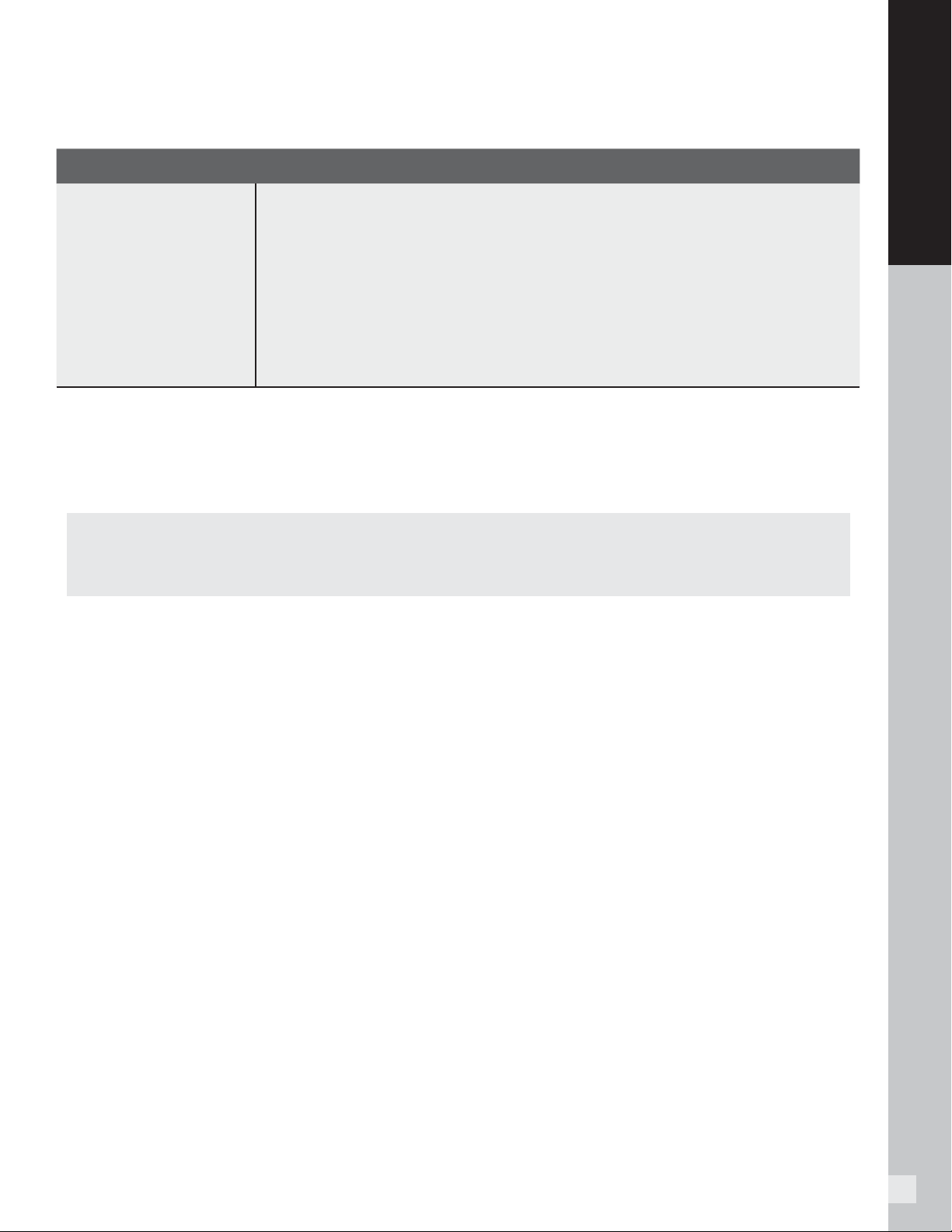
PROBLEM SOLUTION
Job Site Storage
Store decking on a fl at level surface, and ALWAYS use proper supports (dunnage).
DO NOT store directly on the ground. When stacking decking bundles, supports (dunnage)
should start approximately 8-in (203 mm) from each end and be spaced approximately 2-ft
(0.61m) on center. In addition, supports (dunnage) should line up vertically/perpendicular
to the decking product. Adjust support blocks (dunnage) accordingly if bundles are loose.
For Select decking, 1x12 and 1x8 products, the maximum stack height is 12 bundles. For
all other decking products maximum stack height is 14 bundles (IMPORTANT TO NOTE
THAT PROPER DUNNAGE SPACING MUST BE IN PLACE FOR THESE HEIGHTS).
When stacking multiple bundles, ensure that dunnage lines up vertically down through
each stack. ALWAYS cover decking products on site until ready to be installed.
NOTES:
» Refer to www.trex.com to view a general care and cleaning video for Transcend, Enhance, and Select decking.
» Refer to www.trex.com for a care and cleaning guide for Trex Early-Generation Composite and PVC Decking.
*Strait-Line® is a registered trademark of Irwin Industrial Tool Company.
**Use of products containing bleach or acid will lighten the lighten the surface of Trex. Use in an inconspicuous area to determine whether you like the
effect. Neither product will affect the structural integrity of Trex.
***Use of a pressure washer greater than 3100 psi could damage the boards and void the warranty.
****Mr. Clean® and Magic Eraser® are registered trademarks of The Procter and Gamble Company.
*****Scratch Seal™ Clear Sealer Pen is a registered trademark of Dupli-Color Products Company.
8
PLANNING AHEAD
PLANNING
AHEAD
9
PLANNING AHEAD
Trex Decking:
» When installing any Trex decking product, especially
Trex Transcend Tropicals, it is a good idea to mix
and match all of the boards on the job site prior to
installation to ensure an appealing mix of light and
dark tones.
» DO NOT combine Trex Select decking with other Trex
decking products. Trex Select boards are thinner
than Transcend and Enhance boards.
Railing (Including ADA Handrail):
» First, pick the railing style you want.
» Calculate your spanning based on the railing you chose.
» Determine the number of balusters you will need
based on the railing you choose.
NOTE: Trex Transcend and Select railings are made
to be installed at maximum of 6' (1.83 m) or 8'
(2.44 m) on center (depending upon type of railing
you choose). Trex railings are not true 6' (72") or
8' (96") in length. Trex Signature railings are made
to be installed at maximum 6' or 8' CLEAR SPAN
BETWEEN POSTS.
»
Determine post locations prior to installing any
decking. In most cases, posts are usually installed
before decking is installed.
» Confirm with your local building official if ADA
Handrail is required, and if so plan spanning for
posts accordingly to allow for attachment of Trex
ADA Handrail. ADA Handrail requires a span of
6' OC for posts.
» Grill placement: A good recommendation to help
prevent damage to your railing is to not have a grill
too close to your railing. Allow for ample airspace
between the back/sides of your grill to help prevent
charring or staining to the railing.
See pages 57–72 for Transcend railing installation, pages
73–104 for Signature railing installation,
pages 114–123 for Select railing installation, and
pages 124–127 for ADA Handrail installation.
Trex Lighting:
» Plan locations of lights, power supply, timer, and
dimmer. These should be accessible for service if
necessary.
» Install wiring before decking and railing have been
installed.
» DO NOT run wires between joists and deck boards.
See pages 12–24 for Trex
® OutdoorLighting
™
installation.
Trex® RainEscape® Deck Drainage System:
» Plan ahead for deck layout to allow for proper
placement of Trex RainEscape within the joist system.
» Make sure joists are straight and square.
See www.trex.com for more information on Trex
RainEscape recommendations and installation. Trex
RainEscape is manufactured and distributed by Dri-Deck
Enterprises, LLC, under a trademark license with Trex
Company, Inc.
Installing Hot Tubs, Planters, and Seating:
» Plan ahead proper joist spanning if required (this is
especially important if installing a hot tub).
» Refer to page 31 for Trex Decking Span Chart for
specifi c loads.
Call 1-800-BUY-TREX for detailed questions.
Installing Fireplaces and/or Fire Pits With Trex
Decking:
» Determine if fi re will be gas or wood burning
(NOTE: Most fi re pits shown in Trex images are gas
burning).
» For gas, the fi re pit is installed by cutting around the
Trex decking. It is not to be installed on top of Trex
decking. A fi re-resistant material is installed under
the fi re pit and a protective “wall” made from stone or
other fi re-resistant material is installed to hold fi re pit
in place and also protect the decking from heat.
» For wood, fi re pits are not recommended on top
of Trex decking unless using a product called
DeckProtect
®*
. Wood-burning fi re pits can damage
the decking due to extreme heat from the bottom
of the fi re pit and/or burning embers “shooting”
onto the decking. DeckProtect
®
was tested on all
Trex decking and there were no issues with burning
of the decking surface when placed directly under
a standard size portable fi re pit along with the
accompanying rack (NOTE: Rack is not available
for all sizes, so check with manufacturer fi rst
for verifi cation). Trex does recommend that the
PLANNING AHEAD
*DeckProtect® is a registered trademark of Infinite Heat Solutions.
10
PLANNING AHEAD
DeckProtect
®
padding/rack be moved from time to
time for general cleaning underneath. It should be
noted that even when using DeckProtect
®
, burning
embers could “shoot” beyond the protective mat and
burn the deck.
For more information about this product, please
visit their website at www.deckprotect.net or call
1-800-BUY-TREX. DeckProtect
®
is a registered
trademark of Infi nite Heat Solutions.
Installing a Pergola on Trex Decking:
» Keep in mind if you are planning to install a Trex
®
Pergola
™
on your deck, you will need access to the
underside of the deck. Trex Pergola mounts with a
10" x 10" (254 mm x 254 mm) aluminum plate on the
underside of the deck, creating a clamping effect on
both the top and bottom of the deck for maximum
strength. If installed, water barriers and any under
deck coverings will have to be removed to properly
install the pergola posts.
» You need to consider the location of your pergola
posts in respect to joists. However, you do not have
to mount your plates between joists. It is possible to
place blocks on the bottom of the joists and mount
the Trex Pergola brackets through the blocks.
Trex
®
Pergola™ products are manufactured and sold by Home
& Leisure, Inc., d/b/a/ Structureworks Fabrication under a
Trademark License Agreement with Trex Company, Inc. A 25-year
Limited Warranty is provided by manufacturer.
Installing Trex® Spiral Stairs™:
» Refer to www.trexspiralstairs.com for detailed
information on how to plan and install Trex Spiral
Stairs.
Trex
®
Spiral Stairs™ are manufactured and sold by M. Cohen
and Sons, Inc., d/b/a The Iron Shop, under a Trademark License
Agreement with Trex Company, Inc. A 25-year Limited Warranty is
provided by manufacturer.
Installing Trex® Outdoor Kitchens Cabinetry and
Storage™:
» Refer to www.trexoutdoorstorage.com for detailed
information on how to install Trex Outdoor Kitchens
and Cabinetry Storage products.
Trex
®
Outdoor Kitchens Cabinetry and Storage™ products are
manufactured and sold by NatureKast, LLC., under a Trademark
License Agreement with Trex Company, Inc. Warranty is provided
by manufacturer.
PLANNING AHEAD/CONTINUED
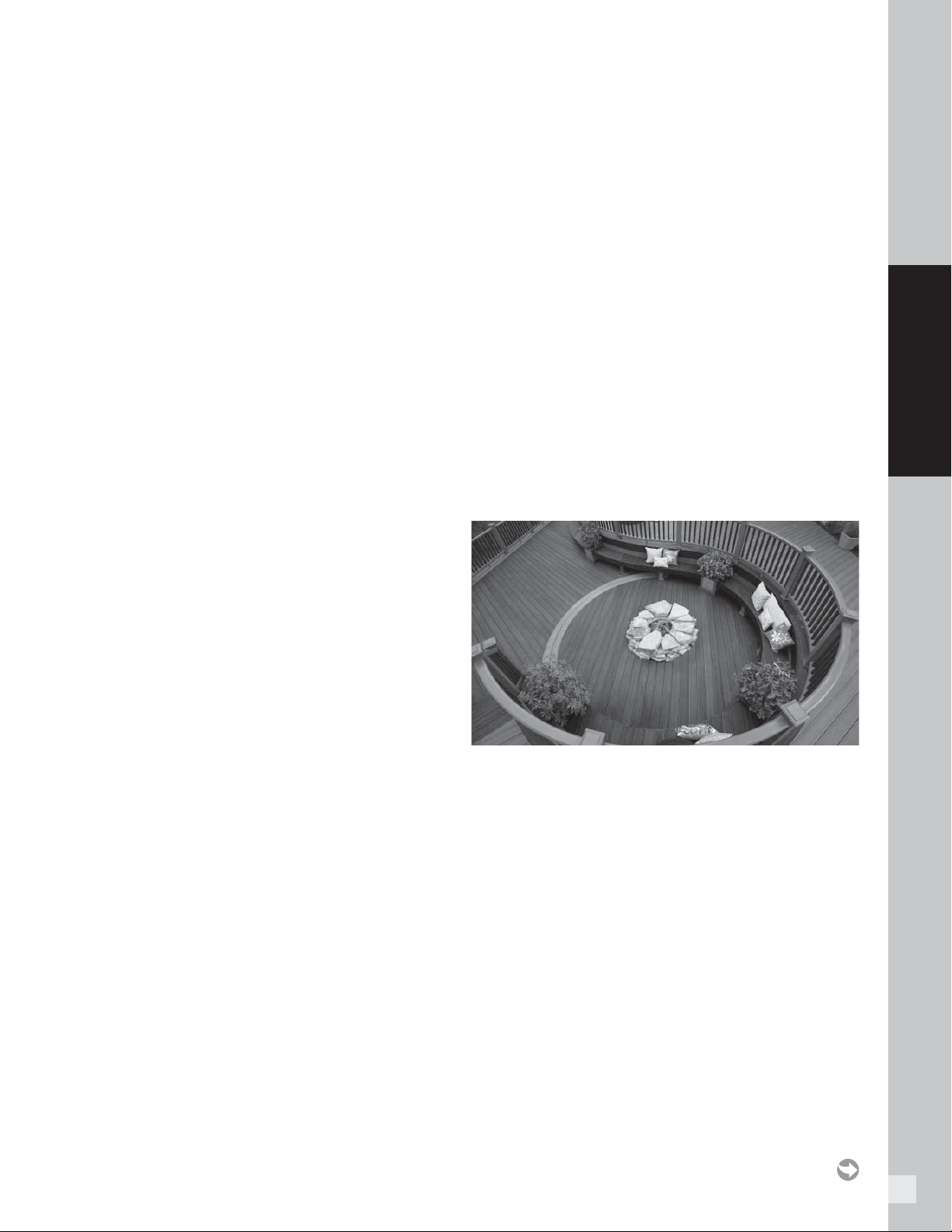
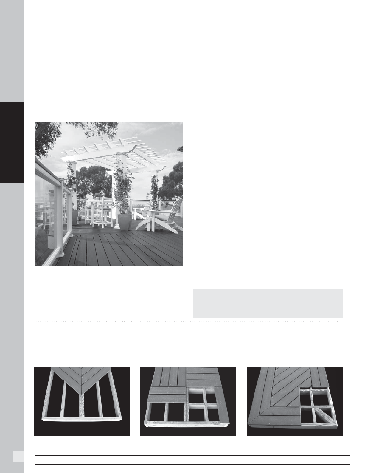
Herringbone Pattern
Tile Pattern
Picture Frame Pattern
Special Patterns
When planning a unique pattern, you will need to adjust the framing to support the surface pattern. Refer to the
span and gapping charts on pages 30–31. Many decks are designed to take advantage of angles, as shown below.
NOTE: You can always reference the Design Tools
Section on www.trex.com for additional planning
ahead aids.
NOTE: Construction methods are always improving. Please refer to www.trex.com for the most up-to-date installation requirements.
11
LIGHTING
LIGHTING
12
LIGHTING
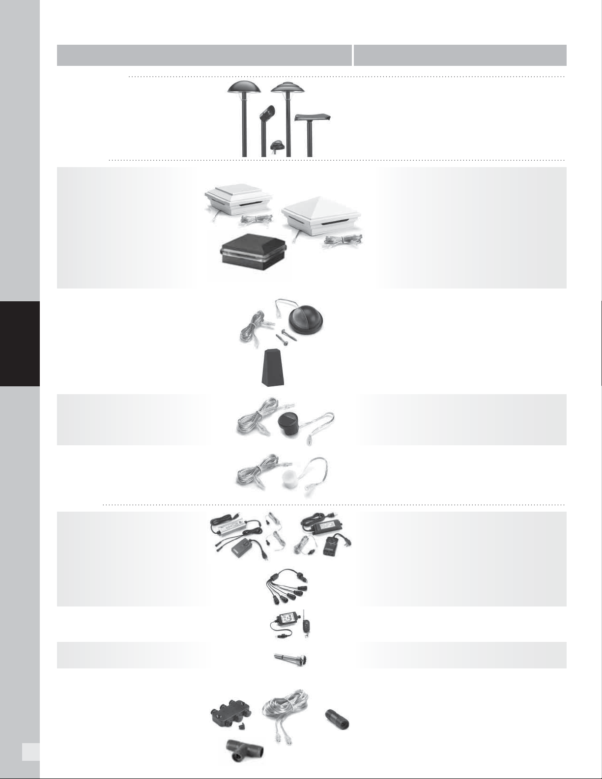
Pyramid or Flat Post Cap Light
» 4" x 4" LED Post Cap Light
[4.55 in x 4.55 in (115 mm x 115 mm)
actual internal dimensions]
Use with Trex 4 in Composite Railing Posts
» 5.5 ft (1.67 m) Male LightHub
®
Lead
Aluminum Post Cap Light
» 2.5" x 2.5" LED Aluminum Post Cap Light
[2.6 in x 2.6 in (66 mm x 66 mm) actual internal dimensions]
Use with Trex 2.5 in Aluminum Railing Posts
» 5.5 ft (1.67 m) Male LightHub Lead
LED Riser Lights
» 4 LED Riser Lights
[1.25 in (31 mm) OD]
» 5.5 ft (1.67 m) Male LightHub Lead
Dimmer
» Single Channel with Remote
1 in (25 mm) Forstner Bit—Pack of 6
Recessed Deck Lights
» 4 LED Recessed Lights
[1 in (25 mm) OD]
» 5.5 ft (1.67 m) Male LightHub Lead
Transformer with Timer
» Output Voltage: 12VDC
» Output Power: 100W or 30W
» Output Current: 8.3A or 2.5A
» Photo-Activated Timer
» 20 ft (6.09 m) LightHub Wire Extension Cable
Multi-zone Transformer Adapter
LightHub Accessories
» 3-Way Splitter
» 6-Way Splitter
» 5 ft (1.52 m) Wire Extension Cable
» 10 ft (3.04 m) Wire Extension Cable
» 20 ft (6.09 m) Wire Extension Cable
» 40 ft (12.19 m) Wire Extension Cable
» 60 ft (18.28 m) Wire Extension Cable
» Female to Female Adapter
LANDSCAPE LIGHTING
DECK LIGHTING
Deck Rail Light
» LED Deck Rail Light
[2.75 in (69 mm) OD]
» 5.5 ft (1.67 m) Male LightHub Lead
Wedge Deck Rail Light
» LED Wedge Deck Rail Light
[1.875 in wide x 3 in high (47 mm x 76 mm) actual dimensions]
Compatible with all Trex Railing Posts
» 5.5 ft (1.67 m) Male LightHub Lead
Outdoor Lighting SKUs
TEXTURED CHARCOAL BLACK: BKLAMPLED C
TEXTURED BRONZE: BZLAMPLEDC
TEXTURED CLASSIC WHITE: WTLAMPLEDC
TEXTURED CHARCOAL BLACK: BKALPOSTLAMPLED
TEXTURED BRONZE: BZALPOSTLAMPLED
TEXTURED CLASSIC WHITE: WTALPOSTLAMPLED
TEXTURED CHARCOAL BLACK: BKRISERLED4PKC
TEXTURED BRONZE: BZRISERLED4PKC
TEXTURED CLASSIC WHITE: WTRISERLED4PKC
Rounded Path Light
Stepped Path Light
Well Light
Multifunction Light
Spotlight*
BKRDPATH2PK, BZRDPATH2PK
BKSPATH2PK, BZSPATH2PK
BKWELL, BZWELL
BKMULTI, BZMULTI
BKSPOT, BZSPOT
*Includes: 36v Step-up Transformer & Female to Female Adapter
DLDIMMER
DLBIT6PK
RECESSLED4PKC
8.3A, 100W: 83DLTRANSFORMER
2.5A, 30W : 25DLTRANSFORMER
DL5TFSPLIT1PK
DL3SPLIT6PK
DL6SPLIT4PK
DL5FTWR4PK
DL10FTWR4PK
DL20FTWR4PK
DL40FTWR2PK
DL60FTWR1PK
DL
FADAP6PK
PYRAMID CAPS
BKPYLEDCAP4X4C
WTPYLEDCAP4X4C
FPPYLEDCAP4X4C
THPYLEDCAP4X4C
VLPYLEDCAP4X4C
GPPYLEDCAP4X4C
RSPYLEDCAP4X4C
FLAT CAPS
BKSQLEDCAP4X4C
WTSQLEDCAP4X4C
FPSQLEDCAP4X4C
THSQLEDCAP4X4C
VLSQLEDCAP4X4C
GPSQLEDCAP4X4C
RSSQLEDCAP4X4C
TEXTURED CHARCOAL BLACK:
BKALCAPLED25
TEXTURED BRONZE: BZALCAPLED25
TEXTURED WHITE: WTALCAPLED25
ACCESSORIES
LIGHTING & DESCRIPTION ITEM NUMBER
13
LIGHTING
A
B
C
D
E
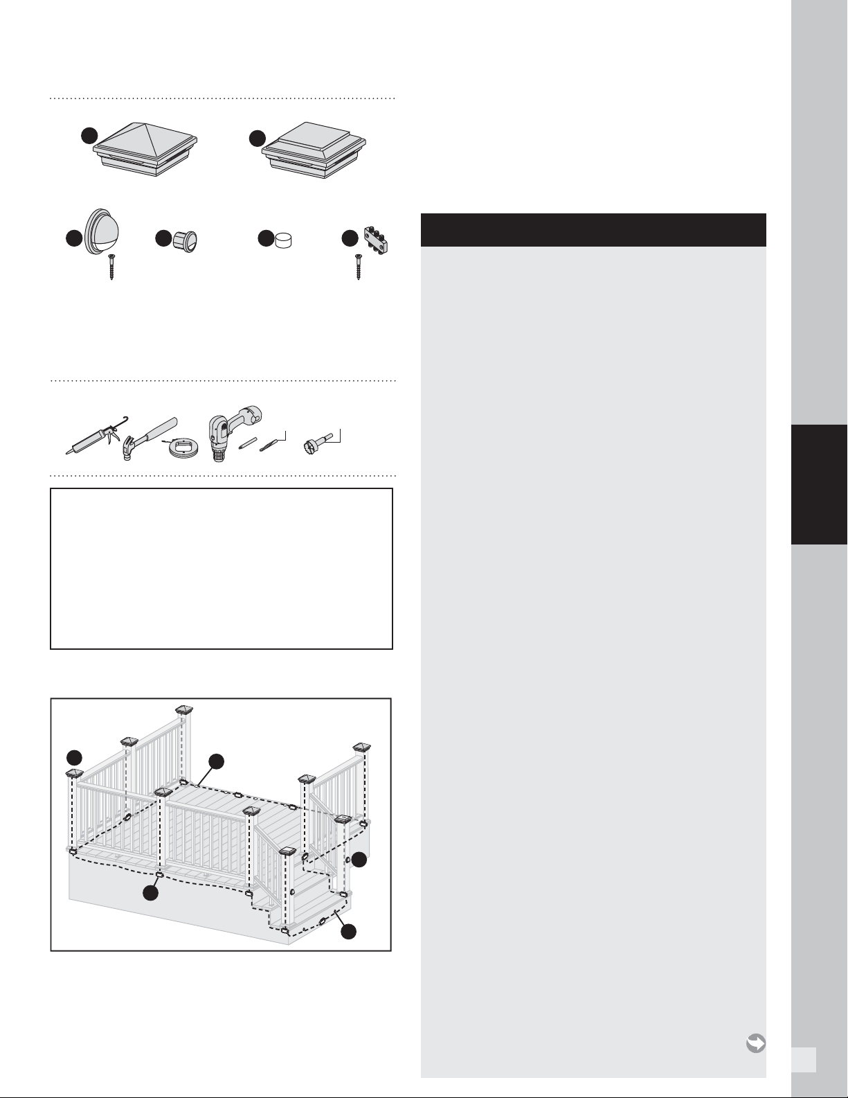
HOW TO INSTALL TREX DECKLIGHTING
PARTS
A
A
Pyramid Post Cap Light
Riser Light SplitterDeck Rail Light Recessed Deck Light
B C D E
x2x2 x2x2
Flat Post Cap Light
1/2"
(13 mm)
1"
(25 mm)
NOTE: All wiring and splitters are mounted to inside of
framing. Picture is just representation of where to place
these in general.
WARNING:
» DO NOT INSTALL DECKLIGHTING IN CLOSE
PROXIMITY TO POOLS OR HOT TUBS AS
CHEMICALS FROM THE WATER CAN DAMAGE
LIGHTING FIXTURES.
» DO NOT INSTALL WIRING UNDER HEAVY
WEIGHT OR LOAD AS THIS CAN DAMAGE
WIRING.
Lighting and Wiring Overview
TOOLS NEEDED
» 5ft, 10ft, 20ft, 40ft, and 60ft connection/extension
wires sold separately (these are male-to-male
connection wires).
HELPFUL TIPS
» Please note that Trex lighting operates on DC
power. NEVER mix AC and DC fi xtures on the
same circuit. Doing so will result in extremely
premature fi xture failure and is not covered by
the Trex limited warranty. You must use a Trex
transformer on all Trex lighting installations.
» Leave slack in wire to make fi xture terminations.
» Recessed lights work well spaced 4' (1.22 m) to
6' (1.83 m) on center around perimeter of deck.
» Deck rail lights work well at changes in levels of a
deck—at the top or the bottom of the stairs, or in
conjunction with post cap lights.
» Recommended riser light placement is two lights
per standard width tread. Otherwise, spacing of
2' to 3' is considered optimal.
» Drill holes perpendicular to the surface, being
careful to hold drill steady, to avoid producing an
enlarged hole. If hole is enlarged, light fixture will
have a loose fit. Use of a flexible outdoor semi-
permanent adhesive (silicone caulk) may be
required to anchor light in place.
» Riser and deck rail light holes can be through
holes. However, recessed light holes should be
drilled to a depth of 3/4" (19 mm). Over-drilled
recessed light holes will require use of silicone
caulk to anchor light in place.
» Splitters should be placed under the deck at the
base of each post that has lighting installed. If not
installing lighting on posts, splitter spacing will be
dependent on spacing of light fixtures.
» Cap all unused female connections with caps
provided or weather-resistant silicone to prevent
water damage or corrosion.
» The splitter is cross-linked so there is no specified
plug for lights versus lead wires.
» Leads attached to each light are approx. 5' 6"
(1.5 m to 1.8 m) in length and have male terminals
to plug into splitter.
» Use a separate dimmer control for each light type
for maximum control (5-way transformer splitter
may be required).
» It is recommended to have power source installed
and turned on when installing lights to ensure all
components work.
» When installing wiring, avoid extreme angles,
pressure, or tension on the wiring, as this can
cause pinching of the wiring and create a
lighting failure.
NOTE: Avoid railing brackets and locations for deck rail
lights when running wires up posts.
NOTE: It is recommended to install wiring and splitters
before decking and railing have been installed. DO NOT
run wires between joists and deck boards.
14
LIGHTING
NOTE: Construction methods are always improving. Please refer to www.trex.com for the most up-to-date installation requirements.
General Information
» Refer to www.trex.com for instructional videos on
how to install Trex Decklighting.
» USE TREX TRANSFORMER ONLY. Use of any other
transformer voids warranty.
Planning
NOTE: When designing your deck, plan locations of
lights, power supply, timer, and dimmer. These should be
accessible for service. Installing a GFCI outlet is REQUIRED
to help prevent damage to lighting from electrical surges.
1. The dimmer remote will work in a
30' (9 m) radius of the unit.
2. Dimmer should be installed in a
dry location.
3. Timer must be installed
vertically with receptacle
facing downwards. Timer must
be at least 1' (.305 m) from
ground level when installed as
per federal safety code height
regulations. Timer must be in view of the sun to use
the dusk/dawn feature.
Installing Wiring
NOTE: It is recommended to install wiring and splitters
before decking and railing have been installed.
» Use male-to-male connection wire (lengths vary)
that will connect to each required splitter.
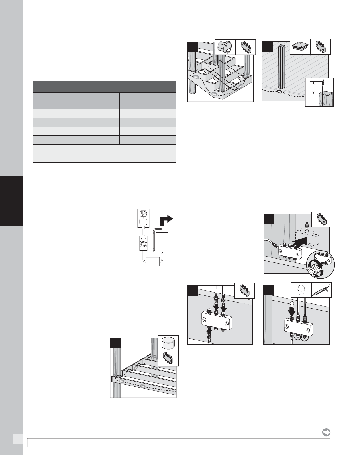
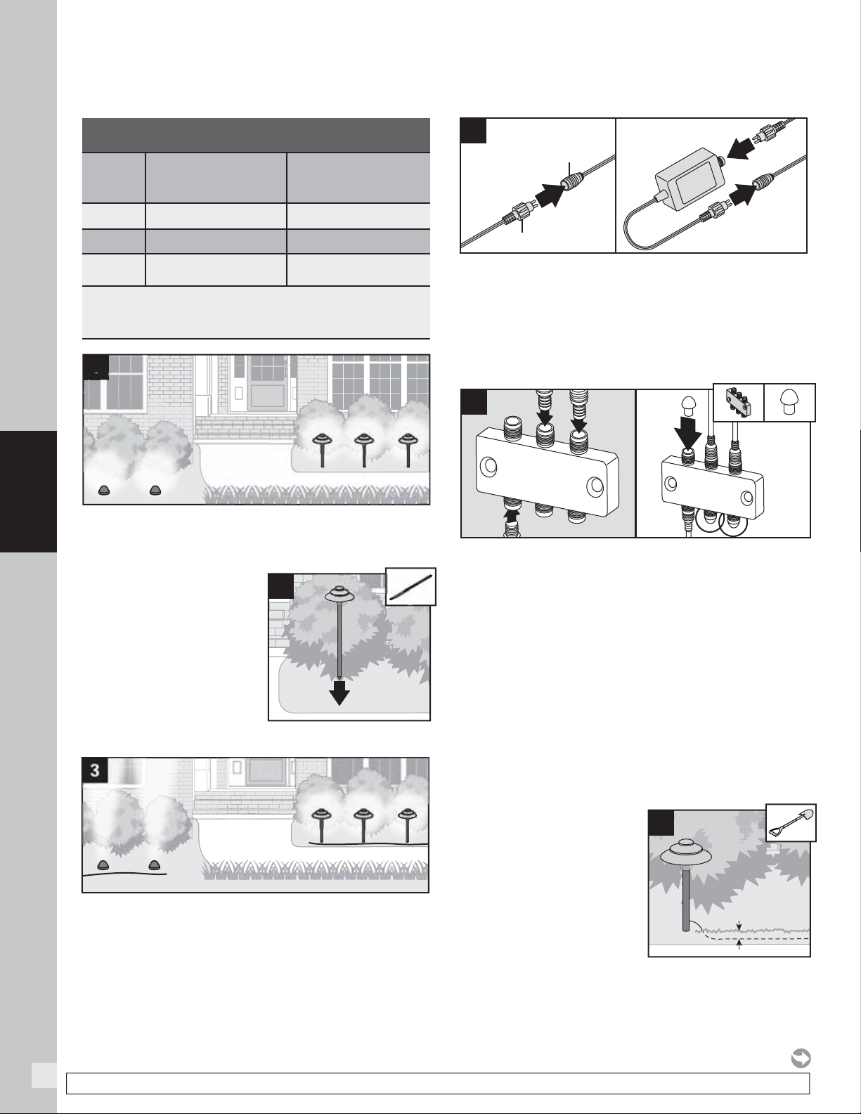
1. Wiring must be run under
decking structure and
behind stringers. DO NOT
run wires between deck
boards and joists. Staple to
frame with cable staples at
least 1/4" (6 mm) wide.
DO NOT crush wire
insulation with staple.
2. Wiring can be run under deck and behind risers.
Staple to frame with cable staples at least 1/4"
(6 mm) wide. DO NOT crush wire insulation with
staple.
3. Remove 5' (1.52 m) lead wire that is connected to post
cap and attach wire to post with male connection at
top of post (female connection would be at bottom of
post and connect into splitter). Avoid running wire on
side of post where railing brackets or deck rail lights
will be installed. Leave approximately 6" (152 mm) of
lead at top to make connections. Staple to frame and
posts with cable staples at least 1/4" (6 mm) wide.
DO NOT crush wire insulation with staple.
Making Connections
1. Install splitters to
inside of framing using
hardware provided.
Install at every post
base where lighting is
present and depending
on spacing in between
each riser and recessed
light.
2. Attach male lead from lights to female connections
on splitter. Also attach male-to-male connection
wires in between each splitter. Continue until all
wiring from lights are attached to splitters and
connector wires are attached in between splitters.
3. Cap off all unused female connections on splitters
using caps provided or weather-resistant silicone.
HOW TO INSTALL TREX DECKLIGHTING/CONTINUED
GFCI
Outlet
Timer
Transformer
To Splitter
Dimmer
(Optional)
1
3
6"
(152 mm)
1
1
2
2
Light
connection
Connection
wire
Connection wire
3
2
TRANSFORMER CAPACITY BY TYPE
8.3A Transformer
(83 DL TRANSFORMER)
Type of
Light
2.5A Transformer
(2.5 DL TRANSFORMER)
Riser 285 90
Recessed 285 90
Post Cap 85 22
Deck Rail 285 90
Above listing is for maximum number of each individual types of lights.
If mixing and matching lighting, contact Trex to determine if more than
one transformer is required.
15
LIGHTING
HOW TO INSTALL TREX DECKLIGHTING/CONTINUED
Timer Operation Instructions
1. Select the mode of operation:
» Dusk to Dawn
» 2–8 hours
» Always “ON”
» “OFF”
Program repeats daily.
When power is fl owing to lights,
green light above POWER is on.
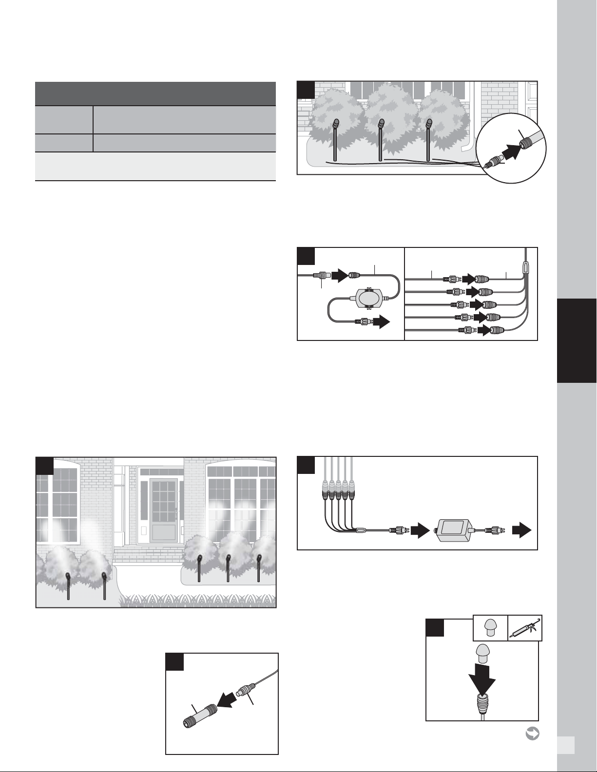
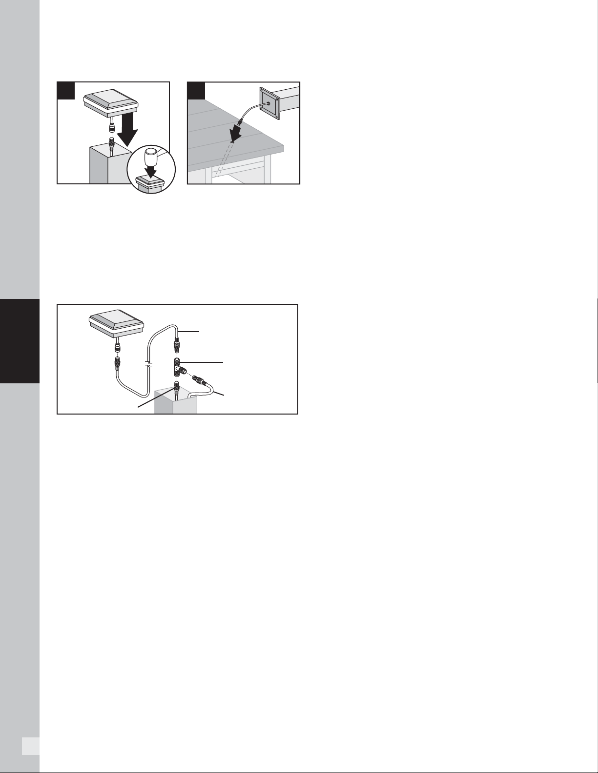
Installing Post Cap Lights
NOTE: Install post cap lights after the railing system,
post sleeve skirt, and post sleeve have been installed.
1. Connect male lead from wiring to female connector
from cap. Also attach male-to-male connection
wires in between each splitter. Continue until all
wiring from lights are attached to splitters as well as
connector wires are attached in between splitters.
(See Making Connections section for details.)
2. After verifying wiring is correct by turning lights on,
attach cap to top of post with silicone caulk.
Installing Deck Rail Lights
NOTE: Instructions shown below are for new deck
installation and are shown BEFORE railing system has
been installed.
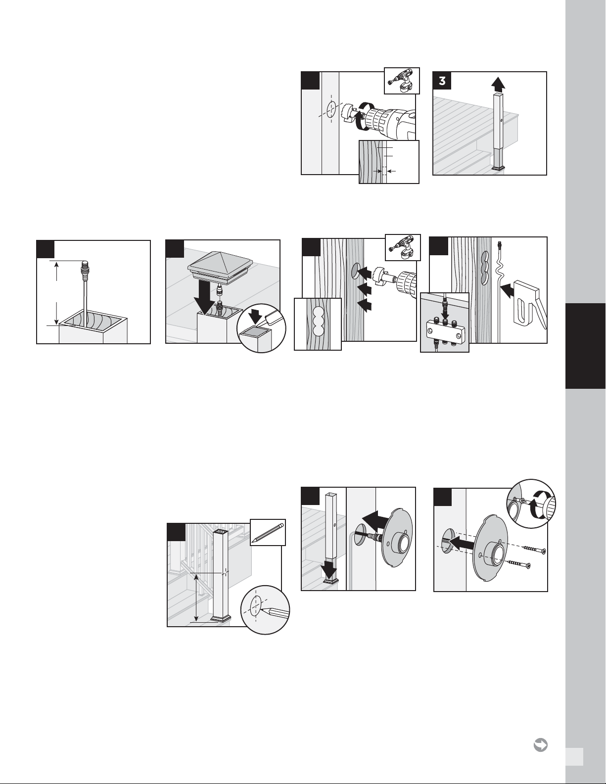
1. Place post sleeve over
pressure-treated post
and mark desired
height, centered on post
sleeve for deck rail light
location.
NOTE: If deck boards are
not installed yet, place a
deck board on framing to
ensure post sleeve is at correct height.
2. Drill a 1" (25 mm) hole through post sleeve. Drill deep
enough to mark location on pressure-treated post.
3. Remove the post sleeve from the post.
4.
Drill out existing hole on pressure-treated post 3/4"
(19 mm) deep. Drill two additional holes vertically
below main hole—this will allow space for wiring after
post sleeve is attached.
5. Leave enough slack at top of lead wire and attach
lead wire to post using staples. Attach lead wire to
splitter under decking.
TIP: To hold lead wire in place at drilled out location use
painters tape.
6. Slide post sleeve back over post. If using a post sleeve
skirt, make sure to install the skirt fi rst. Connect
plug on deck rail light to lead wire and tuck wiring into
previously drilled out pockets on post.
7.
Align holes for screws horizontally
and attach fi xture
base to post with provided screws.
2
2
3
1
6"
(152 mm)
1
1
2
Post
Post
Sleeve
1
2
3
4
1
5
2
2
1
6
1
7
2
16
LIGHTING
NOTE: Construction methods are always improving. Please refer to www.trex.com for the most up-to-date installation requirements.
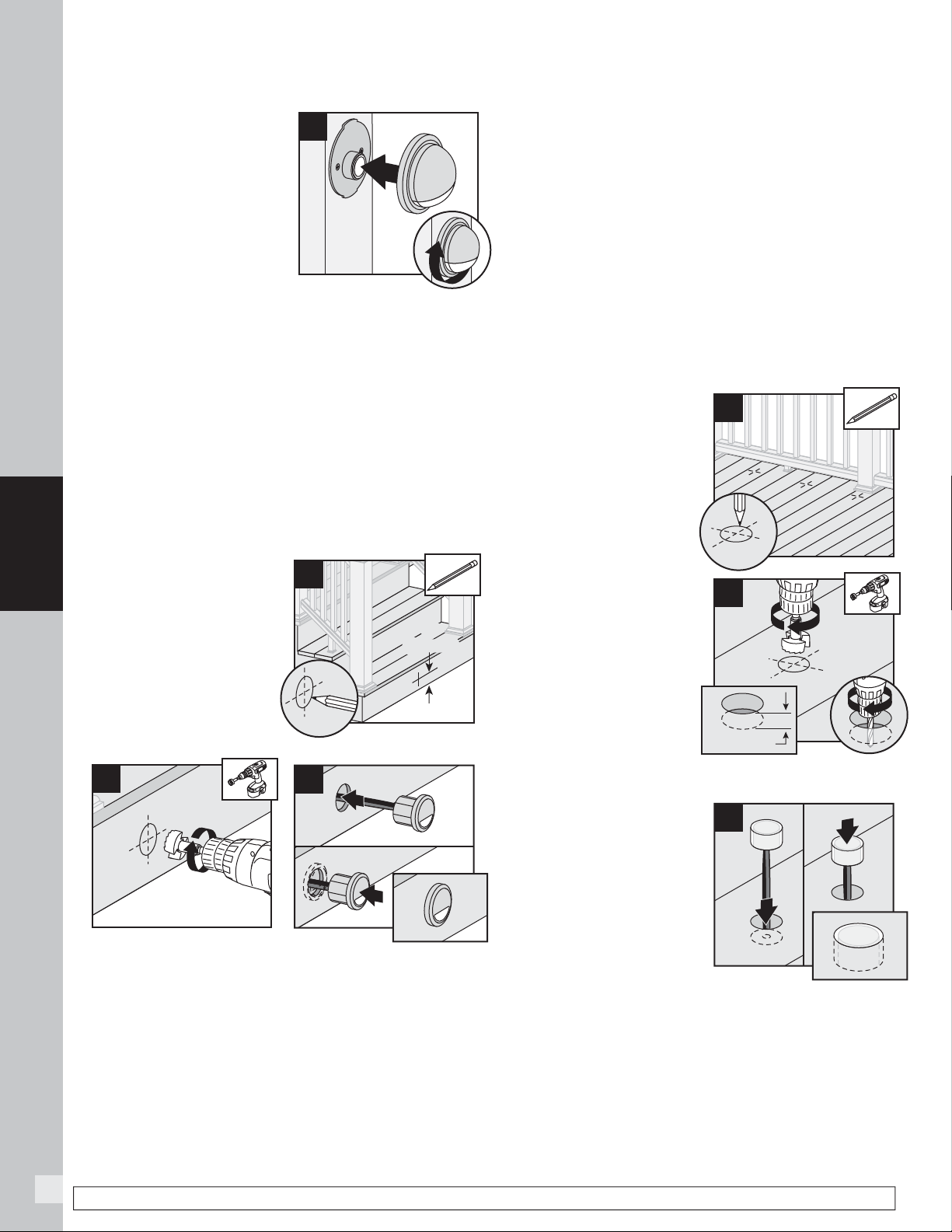
8.
Line up polycarbonate
lens with fi xture housing.
Twist onto fi xture base.
Continue until all wiring
from lights are attached
to splitters as well as
connector wires are
attached in between
splitters. (See Making
Connections section for details.)
NOTE: If railing has already been installed, lead wires
will need to be fi shed through the post sleeve to reach
the desired location for the deck rail light. In some cases,
if the provided lead wire does not fi t (due to connector
size), the wire connectors can be cut off and wire nuts
can be used. Test lights with the power on. If lights that
are wired with this method do not function, then switch
the connector wires.
Installing Riser Lights
NOTE: Install riser lights after stairs and risers have
been installed.
1. Mark locations for
each light, generally
4" (102 mm) above tread.
Consult local codes for
lighting requirements.
NOTE: If possible, avoid
locations over stringers
as holes will be more
diffi cult to create.
2. Drill a 1" (25 mm) diameter hole at least 1" (25 mm)
deep into riser. If riser material is thicker than
1" (25 mm), use a 1/2" (13 mm) drill bit to create a
passage for wires.
3. Thread wires through hole. Press light into hole,
ensuring lens is horizontal.
Make connections behind
stairs from male lead wire from recessed light into
female connection on splitter. Also attach male-to-male
connection wires in between each splitter. Continue
until all wiring from lights are attached to splitters and
connector wires are attached in between splitters.
(See Making Connections section for details.)
NOTE: DO NOT install riser light or deck rail light into top
or bottom rails or balusters.
Installing Recessed Deck Lights
NOTE: Install recessed deck lights after installing decking.
1. Mark locations for lights
in deck boards.
NOTE: If possible, avoid
locations over joists as
holes will be more diffi cult
to create.
2. Drill a 1" (25 mm)
diameter hole 3/4"
(19 mm) deep into deck
board. Hole cannot
go all the way through
deckboard or light will
fall through. Make sure
drill bit is perpendicular
to board. Drill a 1/2"
(13 mm) diameter hole
in base of the fi rst hole through deck board.
3. Thread wires through
hole. DO NOT pull LED
into hole by pulling
on wires. This may
damage wires or LED.
Press light into hole until
fl ush with surface. Make
connections under deck
from male lead wire from
riser light into female
connection on splitter. Also attach male-to-male
connection wires in between each splitter. Continue
until all wiring from lights are attached to splitters and
connector wires are attached in between splitters.
(See Making Connections section for details.)
1
8
2
HOW TO INSTALL TREX DECKLIGHTING/CONTINUED
4"
(102 mm)
4"
(102 mm)
1
2
1
2
3
1
2
1
3
1
2
2
3/4" (19 mm)
17
LIGHTING
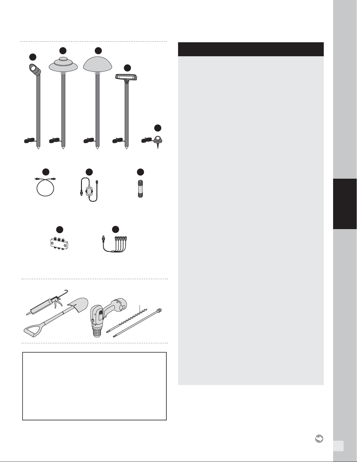
HOW TO INSTALL TREX LANDSCAPELIGHTING
PARTS
A
D
E
I
F
H
B
C
J
Spotlight Stepped
Path Light
Multifunction
Light
Well Light
Splitter
Multi-zone Transformer Adapter
(For use with Trex Spotlight or
for multiple dimmer zones)
Male-to-Male
Connector
Wire
Female-to-Female
Adapter
G
Step-up Transformer
(For use with Trex
Spotlight only)
Round
Path Light
TOOLS NEEDED
3/4"
(19 mm)
HELPFUL TIPS
» Location of Trex LandscapeLighting is up to
customer as to where they would like lighting
components placed. Different length of lead wires
can be purchased depending on the distances
between lights.
» Please note that Trex lighting operates on DC
power. NEVER mix AC and DC fi xtures on the
same circuit. Doing so will result in extremely
premature fi xture failure and is not covered by
the Trex Limited Warranty. You must use a Trex
transformer on all Trex lighting installations.
» Leave slack in wire to make fi xture terminations.
Keep in mind slack will also be required to
properly bury wire.
» Trex Landscape wires are approved for underground
use. Wire is made from silver-coated copper.
» Trex Landscape lights will require the use of a
female-to-female adaptor to connect light to male
connector wire (this adapter is included with each
fi xture and is also sold separately).
» All Trex Landscape lights use male-to-male
connector wires, sold in lengths of 5' (1.52 m),
10' (3.05 m), 20' (6.1 m), 40' (12.2 m), and
60' (18.3 m) (sold separately).
» All lights EXCEPT the spotlight can be wired together
on a circuit.
» Trex Spotlights require different wiring
confi gurations; refer to detailed instructions
on following pages for specifi cs.
» Only use a standard household AC GFCI
protected outlet to help prevent damage from
power surges or lightning.
» When using timer, ensure this is in full view of the
sun if using the dusk/dawn feature.
» It is recommended to have power source attached
when installing lights to ensure all components work.
» When burying wire in live sod use spade shovel
to make a slit in the soil. Bury the wire 1"–3"
(25 mm–76 mm) deep and tamp down the soil.
Water heavily to allow the soil to resettle and
minimize impact on the installation site.
» When installing wiring, avoid extreme angles,
pressure, or tension on the wiring, as this can
cause pinching of the wiring and create a lighting
failure.
WARNING:
BEFORE ANY TREX LANDSCAPELIGHTING
IS INSTALLED, IT IS THE INSTALLERS
RESPONSIBILITY TO ENSURE THAT ALL
UNDERGROUND UTILITIES/LINES ARE
LOCATED (GAS LINES, ELECTRICAL LINES, DATA
LINES, WATER LINES, ETC.) PRIOR TO ANY
WORK BEING DONE.
18
LIGHTING
NOTE: Construction methods are always improving. Please refer to www.trex.com for the most up-to-date installation requirements.
TRANSFORMER CAPACITY BY TYPE
Type of
Light
8.3A (100W)
Transformer
(83 DL TRANSFORMER)
2.5A Transformer
(2.5 DL TRANSFORMER)
Well Light 74 23
Path Light 52 16
Wall Wash
Light
52 16
Above listing is for maximum number of each individual types of lights.
If mixing and matching lighting, contact Trex to determine if more than
one transformer is required. Please visit Trex .c o m for an interactive
capacity calculator.
1. Locate placement of lights and lead wiring. Plan
accordingly if you choose to bury wire under
concrete or other
permanent structures.
2. Place all lights in desired
location. If necessary
use 3/4" (19 mm) auger
with optional extension
in a drill to penetrate
the surface enough to
ensure the fixture is
firmly implanted (SEE
WARNING ON PAGE 17).
3. Run all wires from the power source locations to the
lights on top of the soil, being mindful to leave slack.
Pay special attention if using separate circuits with
independent dimmers (grouping lights by type is
recommended).
4. Connect all lights. Wire the optional dimmer
(recommended) between the main 20' (6.1 m)
transformer to male lead and the transformer
for each circuit. Ensure connections (including
splitters), fixtures, and power sources all work
properly.
4a. Use male-to-male extension cables to make
connections to splitters (all sold separately). Cap
off all unused female connections on splitters using
caps provided or weather-resistant silicone.
5. You can mix and combine all lights except the spotlight
on the same circuit but make sure you
DO NOT exceed the maximum number of lights per
transformer. If running separate circuits with dimmers
on each circuit, using a separate transformer for each
circuit can simplify installation. However, use of a
multi-zone transformer adapter will allow for separate
circuits on the same transformer.
6. It is recommended the installer preview light
placement in the dark to ensure desired effect is
achieved.
7. Once the light, wire, and
splitter placement is
finalized, work from the
light fixtures towards the
power source to bury
the wire to the desired
depth. No more than
1"–3" (25 mm–76 mm) is
required.
1
HOW TO INSTALL TREX LANDSCAPELIGHTING/CONTINUED
(TREX WELL LIGHT, PATH LIGHTS, AND MULTIFUNCTION LIGHTS)
2
1˝–3˝
(25–76 mm)
7
4a
3
Connector Wire
Light
Wire
4
19
LIGHTING
Spotlight
Wire
Female-to-
Female
Adapter
2
TRANSFORMER CAPACITY BY TYPE
Type of Light
8.3A Transformer
(83 DL TRANSFORMER)
Spotlight 12
Above listing is for maximum number of each individual types of lights.
If mixing and matching lighting, contact Trex to determine if more than
one transformer is required.
NOTES:
» Each Trex Spotlight requires use of a dedicated
36V Step-up Transformer (included with each Trex
Spotlight). WARNING: Step-up Transformer DOES
NOT have fault protection, thus care must be taken if
testing.
» Spotlights must use a dedicated line running
directly from the included 36V Step-up Transformer.
Maximum of 12 spotlights are allowed per one
8.3 (100W)-amp transformer. (NOTE: Must use
three multi-zone transformer adapters if installing
all 12 spotlights to single 5A transformer as multi-
zone transformer adapter is designed for up to five
spotlights.) Spotlights have a male lead and require
the use of a female-to-female adaptor to connect
spotlight to connector wire. The spotlight fixture has
a male lead. Install the extension cable accordingly.
DO NOT mix any other lights on the spotlight circuit.
Applying 36V to any other fixture types will result in
very short diode life and will void warranty.
» DO NOT LOOK DIRECTLY INTO SPOTLIGHT
WHEN ON. THIS LIGHT IS VERY BRIGHT.
1. Locate placement of spotlights and lead wiring.
Plan accordingly if you choose to bury wire under
concrete or other
permanent structures.
2. Connect male lead from
light to female to one
end of female adaptor.
3. Connect opposite end of female adaptor to male
connector wire. Choose appropriate length wire
based on your needs. Run all wire on the surface
back to the location of the power supply.
4. Connect opposite end of male connector wire cable
to female end on Step-up Transformer. If using more
than one spotlight, use multi-zone transformer
adapter on Step-up Transformer, making sure
that each spotlight is utilizing its own 36V Step-up
Transformer. Wire the Step-up Transformer or
multi-zone transformer adapter to the 8.3A (100W)
main transformer.
5. If using an optional dimmer (recommended),
simply place the dimmer between the multi-zone
transformer adapter and main transformer.
6. Test lights to ensure power supply, connections,
and light fixtures all work
properly and placement
is appropriate.
7. Ensure that all unused
connections on multi-
zone transformer
adapter are covered
using weather-resistant
silicone.
HOW TO INSTALL TREX LANDSCAPELIGHTING/CONTINUED
(TREX SPOTLIGHT)
4
Connector
Wire
Multi-zone
Transformer
Adapter
To Multi-zone
Transformer Adapter
Step-up
Transformer
5 Step-up
Transformers
3
Female-to-
Female
Adapter
Male
Connector
Wire
5
Multi-zone
Transformer Adapter
5 Step-Up
Transformers
Dimmer
To Main
Transformer
7
20
LIGHTING
8. Ensure that lights are
all working with all
wiring attached prior to
burying any wire.
No more than 1"–3"
(25 mm–76 mm) is
required.
HOW TO INSTALL TREX LANDSCAPELIGHTING/CONTINUED
(TREX SPOTLIGHT)
1˝–3˝
(25–76 mm)
8
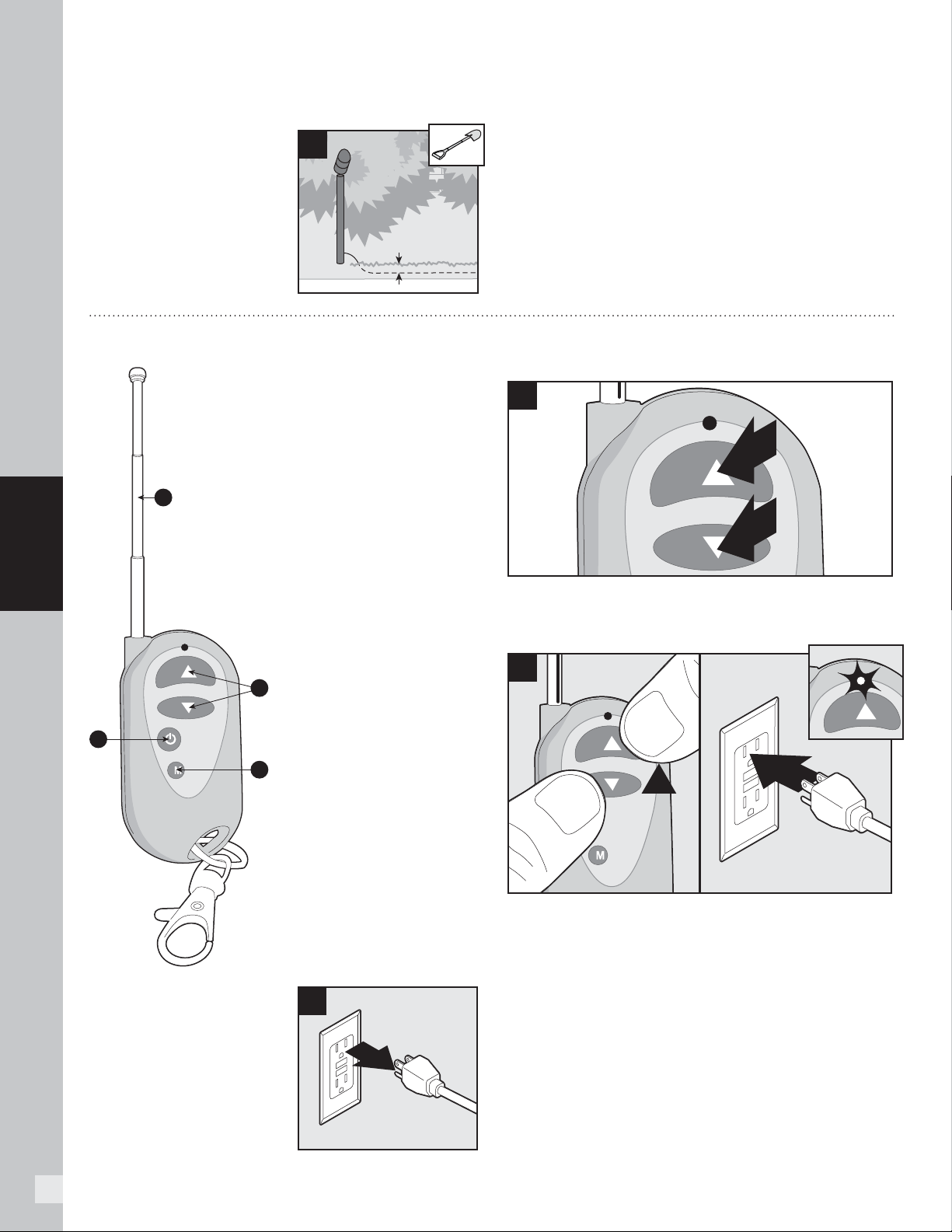
A. ALWAYS keep antenna
fully extended for max
range.
B. Up/Down arrows
gradually dim or brighten
lighting.
C. On/Off button cycles
lights ON/OFF.
D. Mode button cycles
through 3 preset
dimming levels: High,
Medium, Low, and Off.
NOTE: First make sure the
red light is illuminating on
the remote. If there is no red
light and the product is new,
contact 1-800 BUY-TREX
for a replacement. If the
product is not new, the A27
battery is replaceable.
1. Install dimmer per
instructions and make
sure lights are On and
working properly.
2. Unplug the transformer
to turn lights Off.
3. Press and hold both the up and down arrow on the
dimmer remote simultaneously.
4. With the dimmer arrow buttons held down, plug the
transformer back in. The lights should blink once to
confi rm programming.
5. Release the up and down arrows on the remote and
test remote to confi rm proper operation.
HOW TO PROGRAM DIMMER REMOTE
2
3
4
1
2
A
B
C
D
21
LIGHTING
NOTE: Construction methods are always improving. Please refer to www.trex.com for the most up-to-date installation requirements.
HOW TO INSTALL TREX SIGNATURE CAP LIGHT
PARTS
A
Post Cap Light
(includes 5ft male-to-male wire)
9/16" x 6" or Longer
(14 mm x 152 mm)
TOOLS NEEDED
» 5ft, 10ft, 20ft, 40ft, and 60ft connection/extension
wires sold separately (these are male-to-male
connection wires).
HELPFUL TIPS
» Leave slack in wire to make fi xture terminations.
» Post lamps work well at changes in levels of a
deck—at the top or the bottom of the stairs, or in
conjunction with post cap lights.
» Splitters should be used at each post that has
lights and depending on spacing in between each
riser and recessed light.
» Cap all unused female connections with caps
provided or weather-resistant silicone to prevent
water damage or corrosion.
» The splitter is cross-linked so there is no specified
plug for lights versus lead wires.
» Leads attached to each light are approx.
5.5' (1.67 m) in length and have male terminals
to plug into splitter.
» Use a separate dimmer control for each light type
for maximum control.
» It is recommended to have power source on when
installing lights to ensure all components work.
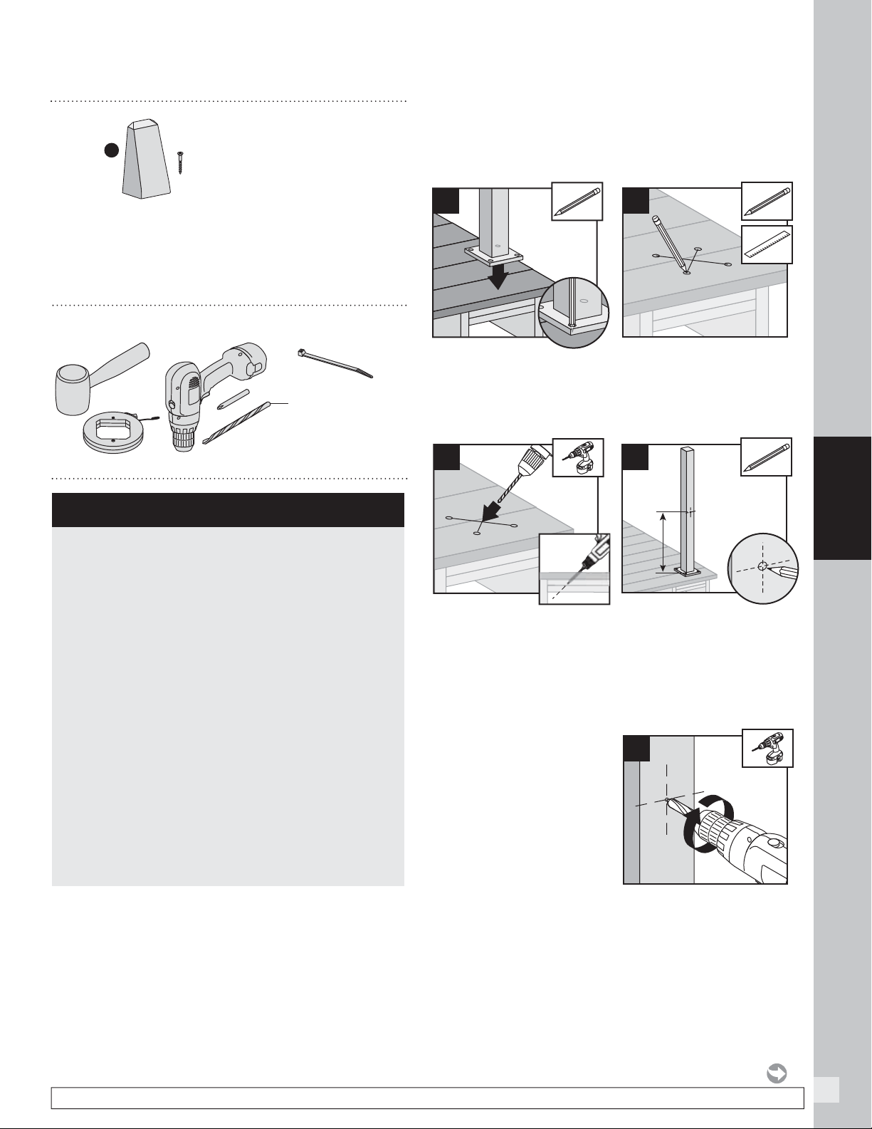
Installing Post Cap Lights
NOTE: Instructions shown below are for new deck
installation and are shown BEFORE railing system has
been installed.
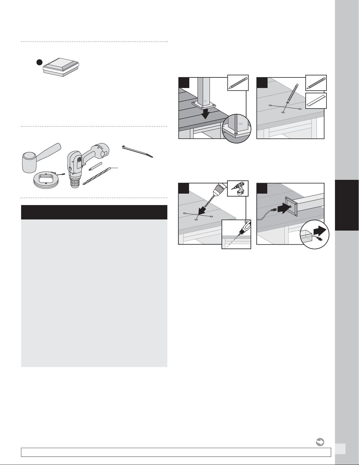
1. Before attaching post to deck, locate placement of
post and mark desired bolt locations.
2. Using a straight edge, mark an “X” between the four
bolt locations.
3. Using a 9/16" (14 mm) x 6" (152 mm [or longer]) drill
bit, drill a diagonal hole through the decking and
blocking. Ensure that the angle will allow wire to not
be pinched by support plate under blocking (if using
Trex ALPOSTHWDECK mounting kit). (See Making
Connections section for details.)
4. Turn post upside down and fi sh 5' male-to-male wire
(provided) through hole in baseplate.
1
3
2
4
22
LIGHTING
HOW TO INSTALL TREX SIGNATURE CAP LIGHT/CONTINUED
5. Connect the female connector on the post cap light
to this wire and, using a rubber mallet, gently tap the
cap onto top of post until it is secure.
6. Turn post over and carefully fi sh wire through hole
created in Step 3 to underside of the deck. Ensure
exit point of wire under blocking will not be pinched
by ALPOSTHWDECK plate.
7. Mount post per instructions.
NOTE: If connecting a Trex Wedge Deck Rail Light as well,
a 3-way adapter and extra 5' male-to-male wire (not
provided) can be used inside the post so that only one
wire must be run through the hole in the base of the post
(and post blocking). This is optional.
1
5
2
6
5' Male-to-Male Wire
(from Post Cap)
5' Male-to-Male Wire
(from Post Lamp)
5' Male-to-Male Wire
(from Baseplate hole)
3-Way Splitter
23
LIGHTING
NOTE: Construction methods are always improving. Please refer to www.trex.com for the most up-to-date installation requirements.
HOW TO INSTALL TREX WEDGE DECK RAIL LIGHT
PARTS
A
x3x3
Wedge Deck Rail Light
(includes 5ft male-to-male wire)
9/16" x 6" or Longer
(14 mm x 152 mm)
TOOLS NEEDED
» 5ft, 10ft, 20ft, 40ft, and 60ft connection/extension
wires sold separately (these are male-to-male
connection wires).
HELPFUL TIPS
» Leave slack in wire to make fi xture terminations.
» Deck rail light work well at changes in levels of a
deck—at the top or the bottom of the stairs, or in
conjunction with post cap lights.
» Splitters should be used at each post that has
lights and depending on spacing in between each
riser and recessed light.
» Cap all unused female connections with caps
provided or weather-resistant silicone to prevent
water damage or corrosion.
» The splitter is cross-linked so there is no specified
plug for lights versus lead wires.
» Leads attached to each light are approx.
5.5' (1.67 m) in length and have male terminals
to plug into splitter.
» Use a separate dimmer control for each light type
for maximum control.
» It is recommended to have power source on when
installing lights to ensure all components work.
Installing Post Lamps
NOTE: Instructions shown below are for new deck
installation and are shown BEFORE railing system has
been installed.
1. Before attaching post to deck, locate placement of
post and mark desired bolt locations.
2. Using a straight edge, mark an “X” between the four
bolt locations.
3. Using a 9/16" (14 mm) x 6" (152 mm [or longer]) drill
bit, drill a diagonal hole through the decking and
blocking. Ensure that the angle will allow wire to not
be pinched by support plate under blocking (if using
Trex ALPOSTHWDECK mounting kit).
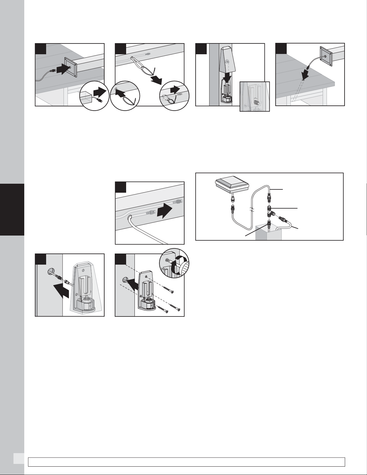
4. Locate placement of post lamp. Mark entry point of
the wire.
5. Drill 9/16" (14 mm) hole
where wire will enter
post.
1
3
5
2
4
24
LIGHTING
NOTE: Construction methods are always improving. Please refer to www.trex.com for the most up-to-date installation requirements.
10. Slide light cover down over backing plate, adjusting
mounting screws as necessary to achieve a tight fi t.
11. Turn post over and carefully fi sh wire through hole
created in Step 3 to underside of the deck. Ensure
exit point of wire under blocking will not be pinched
by ALPOSTHWDECK plate.
12. Mount post per instructions.
NOTE: If connecting a Signature post cap light as well,
a 3-way adapter and extra 5' male-to-male wire (not
provided) can be used inside the post so that only one
wire must be run through the hole in the base of the post
(and post blocking). This is optional.
6. Turn post upside down and fi sh 5' male-to-male wire
(provided) through hole in baseplate.
7a. If connecting a Wedge Deck Rail Light only, pull wire
through hole.
TIP: Insert a zip-tie loop (or small grabber tool) through
9/16" (14 mm) hole. Fish wire through loop in zip-tie.
Pull wire through hole with zip-tie.
7b. If connecting a
Signature post cap light
as well, and using the
3-way splitter (see note
after Step 12), simply
run one wire through the
hole created in Step 5
to the top of the post.
8. Connect male connector to female connector on
light housing.
9. Place light and attach backing plate to post with
three screws (provided).
6
8
10
3
7a
1
2
7b
5' Male-to-Male Wire
(from Post Cap)
5' Male-to-Male Wire
(from Post Lamp)
5' Male-to-Male Wire
(from Baseplate hole)
3-Way Splitter
1
9
2
11
HOW TO INSTALL TREX WEDGE DECK RAIL LIGHT/CONTINUED
25
DECKING
DECKING
26
DECKING
Trex Decking, Porch Flooring & Fascia
XX = COLOR PREFIX:
HG Havana Gold
IM Island Mist
LR Lava Rock
SR Spiced Rum
TT Tiki Torch
FP Fire Pit
GP Gravel Path
RS Rope Swing
TH Tree House
VL Vintage Lantern
MB Madeira
PG Pebble Grey
SD Saddle
WG Winchester Grey
WB Woodland Brown
BD Beach Dune
CS Clam Shell
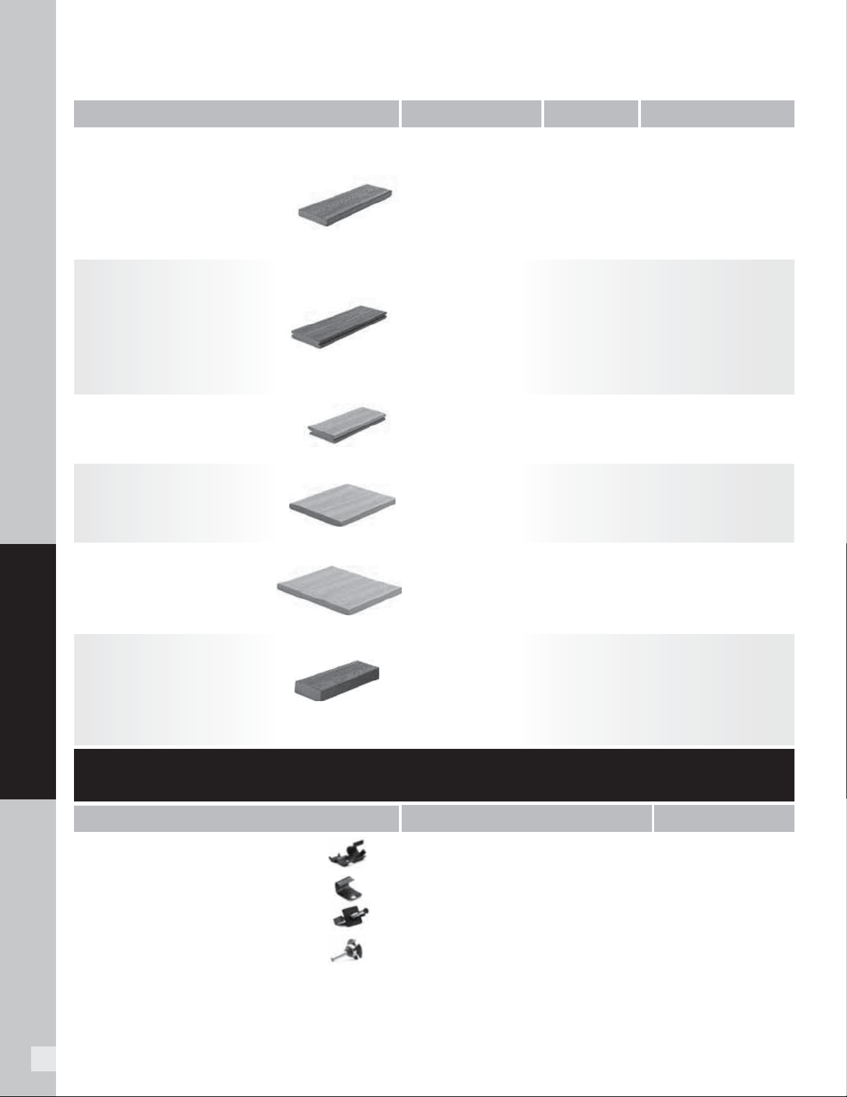
1" Square-Edge Board
Actual dimensions:
Transcend & Enhance: .94 in x 5.5 in x 12 ft / 16 ft / 20 ft
(24 mm x 140 mm x 365 cm / 487 cm / 609 cm)
Select: .82 in x 5.5 in x 12 ft / 16 ft / 20 ft
(20 mm x 140 mm x 365 cm / 487 cm / 609 cm)
1 x 6 x 12' Transcend
1 x 6 x 16' Transcend
1 x 6 x 20' Transcend
1 x 6 x 12' Enhance
1 x 6 x 16' Enhance
1 x 6 x 20' Enhance
7/8 x 6 x 12' Select
7/8 x 6 x 16' Select
7/8 x 6 x 20' Select
1 x 6 x 12' Transcend
1 x 6 x 16' Transcend
1 x 6 x 20' Transcend
1 x 6 x 12' Enhanc
e
1 x 6 x 16' Enhance
1 x 6 x 20' Enhance
7/8 x 6 x 12' Select
7/8 x 6 x 16' Select
7/8 x 6 x 20' Select
1 x 8 x 12' Transcend
1 x 8 x 12' Enhance
1 x 8 x 12' Select
1 x 8 x 12' Universal White
1 x 12 x 12' Transcend
1 x 12 x 12' Enhance
1 x 12 x 12' Select
1 x 12 x 12' Universal White
2 x 4 x 16' Transcend
2 x 6 x 12' Transcend
2 x 6 x 16' Transcend
2 x 6 x 20' Transcend
2 x 6 x 12' Select
2 x 6 x 16' Select
2 x 6 x 20' Select
1 x 4.5 x 12' Transcend Porch
1 x 4.5 x 16' Transcend Porch
XX010612TS48
XX010616TS48
XX010620TS48
XX010612ES48
XX010616ES48
XX010620ES48
XX010612SS64
XX010616SS64
XX010620SS64
XX010612TG48
XX010616TG48
XX010620TG48
XX010612EG48
XX010616EG48
XX010620EG48
XX010612SG64
XX010616SG64
XX010620SG64
XX010812TS60
XX010812ES60
XX010812SS60
WW010812ES60
XX011212TS40
XX011212ES40
XX011212SS40
WW011212ES40
XX020416TS48
XX020612TS32
XX020616TS32
XX020620TS32
XX020612SS32
XX020616SS32
XX020620SS32
XX010512TP60
XX010516TP60
HG, IM, LR, SR, TT, FP, GP, RS, TH, VL
BD, CS, SD
MB, PG, SD, WG, WB
HG, IM, LR, SR, TT, FP, GP, RS, TH, VL
BD, CS, SD
MB, PG, SD, WG, WB
HG, IM, LR, SR, TT, FP, GP, RS, TH, VL
BD, CS, SD
MB, PG, SD, WG, WB
WOOD GRAIN WHITE
HG, IM, LR, SR, TT, FP, GP, RS, TH, VL
BD, CS, SD
MB, PG, SD, WG, WB
WOOD GRAIN WHITE
HG, IM, LR, SR, TT
HG, IM, LR, SR, TT
MB, PG, SD, WB
GP, SR
CONNECTCLIP
CLIPPAIL
GUNCLIP
UNIVSTARTCLIP
UNIVCONCLIP
DA00002
ROUTBIT
50 sq. ft (4.6 m
2
) box
500 sq. ft (46.5 m
2
) bucket
500 sq. ft (46.5 m
2
) bucket with collated pneumatic screws
400 sq. ft (37 m
2
) bag
50 sq. ft (4.6 m
2
) box
500 sq. ft (46.5 m
2
) bucket
Router Bit
Connector Clip (stainless steel)
Gun Pail
Universal Starter Clip
Universal Fastener (glass-filled nylon)
Router Bit
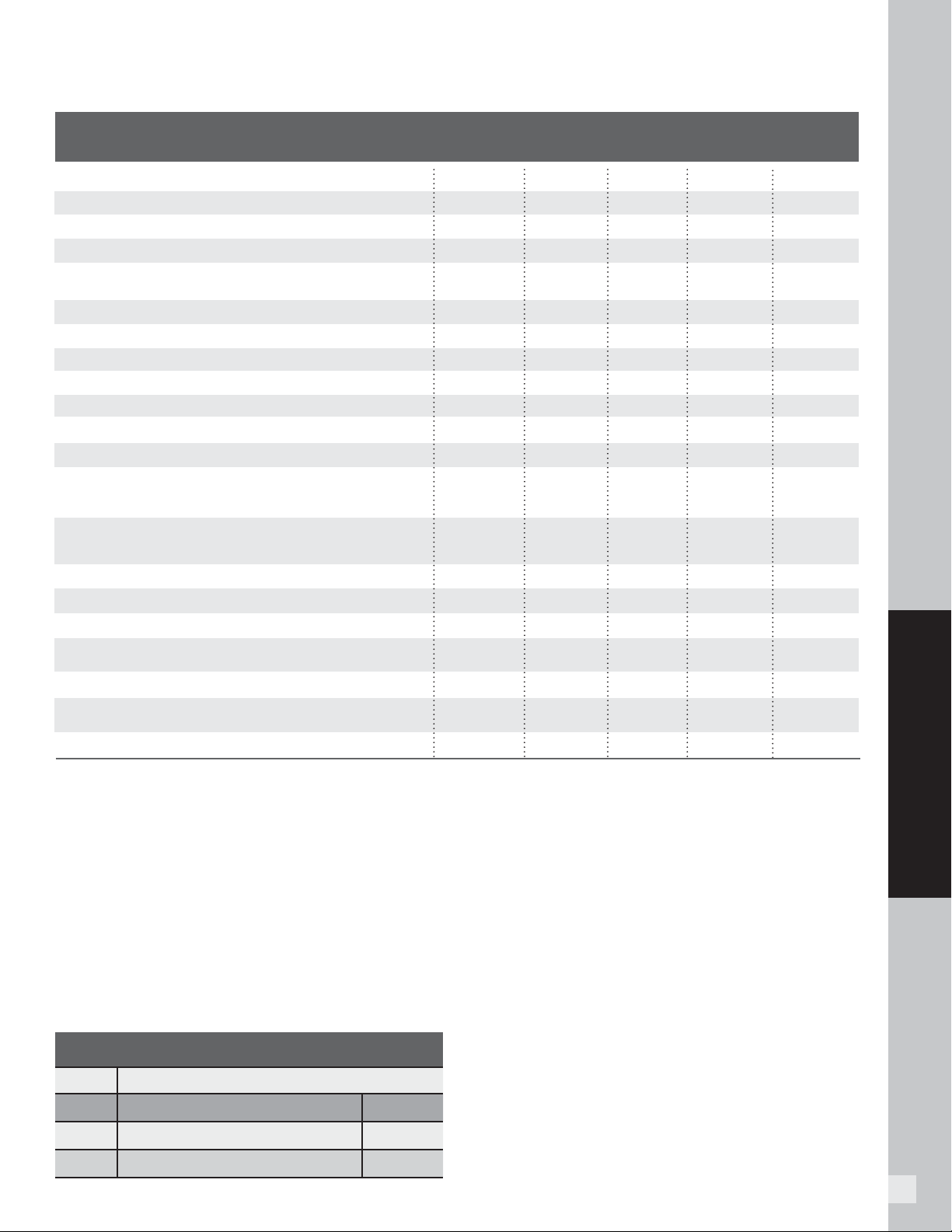
1" Grooved-Edge Board
Actual dimensions:
Transcend & Enhance: .94 in x 5.5 in x 12 ft / 16 ft / 20 ft
(24 mm x 140 mm x 365 cm / 487 cm / 609 cm)
Select: .82 in x 5.5 in x 12 ft / 16 ft / 20 ft
(20 mm x 140 mm x 365 cm / 487 cm / 609 cm)
1" Grooved Porch Floor Board
Actual dimensions:
.94 in x 4.5 in x 12 ft / 16 ft (24 mm x 114 mm x 365 cm / 487 cm)
Can also be used for decking applications.
1" x 8" Fascia
Actual dimensions:
Transcend, Enhance, Select, Universal White:
.56 in x 7.25 in x 12 ft (14 mm x 184 mm x 365 cm)
1" x 12" Fascia
Actual dimensions:
Transcend, Enhance, Select, Universal White:
.56 in x 11.375 in x 12 ft (14 mm x 288 mm x 365 cm)
2" Square-Edge Board
Actual dimensions:
Transcend 2x4: 1.3 in x 3.4 in x 16 ft
(33 mm x 86 mm x 487 cm)
Transcend & Select 2x6: 1.3 in x 5.5 in x 12 ft / 16 ft / 20 ft
(33 mm x 140 mm x 365 cm / 487 cm / 609 cm)
PROFILE
DESCRIPTION ITEM NUMBER COLORS
TREX HIDEAWAY
®
HIDDEN FASTENING SYSTEM
DESCRIPTION ITEM NUMBER
27
DECKING
DECKING AND FASCIA RECOMMENDED FASTENERS
NOTES:
» 2-3/4" (70 mm) or 3" (76 mm) screws can be used with Trex 2x6 product.
» Muro T-Screw M-TX0300SEP listed above is approved for 2x6 decking
(can also be used with standard 1" (25 mm) decking as listed above). This
screw is collated and can be used with Muro Auto Feed Screw Gun FDVL41
Speed Driver. (NOTE THIS IS NOT A COLOR-MATCH SCREW.)
» All decking products are approved for use with Trex Hideaway Hidden
Fasteners, thus all decking products can be routed according to our
instructions.
» Simpson Strong Tie Deck Drive DCU Composite Screw in collated versions
works with Quik Drive gun.
» * Fascia system screws listed above can only be used with composite
fascia profi les, and cannot be used with standard thickness decking
boards used as fascia. Use stainless steel screws near water applications.
» ** Not for use with sleeper systems. Refer to FastenMaster® literature for
more information.
» ***Collated Cap-Tor xd products cannot be used with Trex Escapes.
MINIMUM FASTENER SIZE
SCREWS
Profile Length No.
1x6 2-1/2" (63.5 mm) or 2-3/4" (70 mm) #8, #10
2x6 2-3/4" (70 mm) or 3" (76 mm) #8, #10
1x6 (25 mm X 152 mm), 2x6 (51 mm x 152 mm)
If any condition occurs which is attributable to the use of non-
recommended fasteners, such condition shall not be covered under
Trex’s Limited Warranty.
FastenMaster®
TrapEase® II, TrapEase® 3, FastenMaster®
TrimTop
™
, and
Cortex® are registered trademarks of OMG, Inc.
Camo® and Marksman Pro® are registered trademarks of National Nail
Corp.
Quik Drive® and Dexxter
™
are registered trademarks and
Composi-Lok
™
is a trademark of Simpson Strong-Tie Company, Inc.
NailScrews® is a registered trademark of Universal Fastener
Outsourcing, LLC.
Scrudini
™
is a trademark of Swan Secure Products, Inc.
DeckFast® Cap-Tor® xd and HeadCote® Cap-Tor® xd are registered
trademarks of Starborn Industries Inc.
C-Deck Exterior Star Deck Composite Deck Screw is a product of Screw
Products Inc.
Phillips II Plus® is a registered trademark of Phillips Fasteners LLC.
SplitStop™ screws are a registered trademark of Titan Metal Werks, Inc.
Trex recommends the use of two screws per joist.
All recommended screws are designed to be installed fl ush with
decking surface, DO NOT countersink screws.
Use recommended stainless steel screws in any areas near
bodies of saltwater.
TREX
PRODUCT LINES
Transcend
®
Enhance
®
Select
®
Accents
®
Escapes
®
Trex Hideaway
®
Universal Hidden Fastener X X X X X
Trex Hideaway
®
Connector Clip X X X X
TigerClaw
®
TC-G Hidden Fastener X
FastenMaster
®
TrapEase 3 Ultimate Composite Deck Screw X X X X X
Simpson Strong Tie Deck Drive™ DCU Composite Screw
(Collated and Handdrive) X X X X
Quick Drive
®
Composi-Lok Deck Screw X
Dexxter
®
Composite Screw – 6 Lobe Drive Only X X X X
SplitStop™ Titan III Composite Screw X X X
UFO Ballistic NailScrews
®
X
Fastenmaster
®
TrimTop Screw X
Scrudini™
Hand Drive Screws X
Camo™ Marksman Pro
®
X
Starborn
®
Cap-Tor
®
xd - Epoxy Coated and Headcote
®
Stainless
(available collated for Muro CH7390 Driver***) X X X X X***
(2" are approved for sleeper and roof top applications only)
Starborn
®
Pro-Plug
®
System for PVC and Composite
(Epoxy Coated and Stainless) X X X
(2" are approved for sleeper and roof top applications only)
Screw Products C-Deck Exterior Star Drive Composite Deck Screw X X X
Phillips II Plus
®
Pozisquare X X X
Cortex
®
Concealed Fasteners** X X X X
Muro
®
T-Screw Torx Stainless Steel Screw – Collated
(TX0212SFD or M-TX0300SEP) X X X X
Kameleon™ GRKFasteners™ X
Starborn
®
DeckFast
®
Fascia System -
Epoxy Coated* and HeadCote
®
Stainless* X X X
SplitStop™ Fascia Screws* (uses SplitStop™ Fascia Bit) X X X
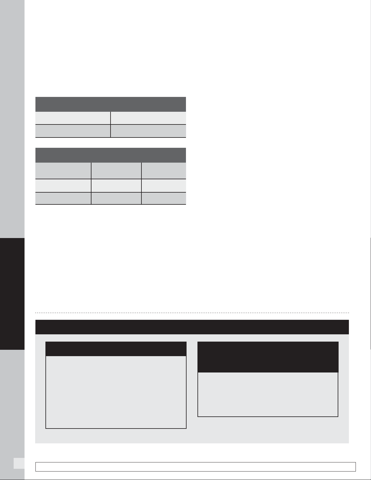
28
DECKING
NOTE: Construction methods are always improving. Please refer to www.trex.com for the most up-to-date installation requirements.
TREX
®
FASCIA INSTALLATION RECOMMENDATIONS
Trex Fascia utilized around the perimeter of a deck must
be gapped with the same requirements as Trex decking
to allow for air fl ow and expansion/contraction of the
fascia.
The gapping requirements are as follows:
WIDTH-TO-WIDTH GAP
Below 40°F (4.5°C) 3/8" (10 mm)
Above 40°F (4.5°C) 1/4" (6 mm)
END-TO-END/END-TO-WIDTH & ABUTTING GAP
End-to-End/
End-to-Width
Abutting
Below 40°F (4.5°C) 3/16" (5 mm) 1/2" (13 mm)
Above 40°F (4.5°C) 1/8" (3 mm) 1/4" (6 mm)
When Using Approved Fascia Fasteners:
NOTE: The fasteners listed below can only be used with
1x8 or 1x12 fascia product, and cannot be used with
decking product that is being used as fascia trim or stair
risers.
Trex recommends the use of Starborn
®
DeckFast
®
Fascia System, for all composite Trex fascia profi les.
For near water applications, you can also use Fascia
System HeadCote
®
stainless steel screws. Refer to
manufacturer recommendations for specifi cs if this is
required.
If using 2 x 8 framing, use two fascia screws every 18
"
(457 mm)
. If using 2 x 10 or greater framing, use three
fascia screws every 18
" (457 mm). Follow manufacturer
instructions for further install instructions and ALWAYS
remember to gap fascia properly. A secondary glue is
not required when using these fasteners.
NOTE: The above fasteners can ONLY be used with
fascia profi les. If using deck boards as fascia, refer to the
recommendations in next column on this page.
If Using other Fasteners and/or Using Decking
product in Fascia/Stair Riser Applications:
While Trex prefers the previous methods of attachment,
as these are the very best options, there are also other
recommendations that can be followed for fascia or
deck boards being used for fascia. Use three Trex
recommended composite decking screws every 12
"
(305 mm).
ALWAYS refer to manufacturer instructions to
ensure that recommended screws can be used for fascia
applications. The top screw should be placed 1
" (25 mm)
from the top of the rim joist, the second screw in the
center of the rim joist, and the third screw 1” (25 mm)
from the bottom of the rim joist.
IN ADDITION, also use a weather-resistant,
construction-grade adhesive (adhesives that work with
wood will work with Trex products) as a SECONDARY
fastener when attaching fascia. Remember to wipe
away any excess before drying or allowing to drip on
other Trex surfaces.
ADDITIONAL TIPS:
» 10
" (254 mm) rim joists allow for an easier and more
aesthetically pleasing installation.
» Miter cuts at butt joints and corners allow for a more
aesthetically pleasing installation.
FRAMING AND FASTENING TIPS
FASTENING TIPS FOR TREX ESCAPES*
You can fasten Trex Escapes with the
recommended fasteners at least 1/2" (13 mm)
and not more than 4" (102 mm) from the board
edge without splitting. You do not have to pre-
drill with Trex Escapes.
* Use Trex Universal Hideaway Hidden Fasteners
for Escapes grooved product. This includes
additional screws for installation.
FASTENING TIP FOR TREX ESCAPES,
TREX TRANSCEND, TREX ENHANCE, AND
TREX SELECT
NOTE: When using pneumatic or battery-
operated equipment, adjust the pressure so
that you only shoot the head of the screw to be
fl ush with the board’s cap. DO NOT shoot the
fastener head completely through the cap.
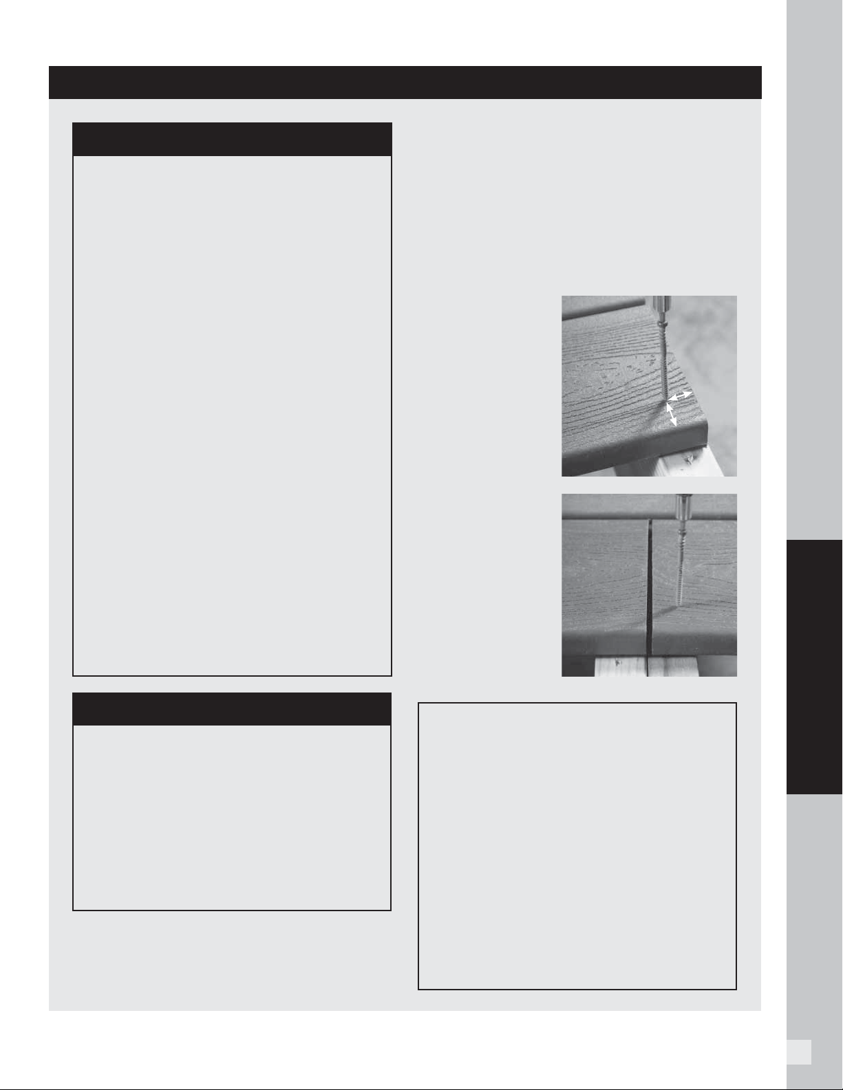
29
DECKING
structural material be used as the framing and
joists. One option is using Trex Elevations
®
steel
deck framing. Refer to www.trex.com for more
information on Trex Elevations. Check your local
building codes for restrictions. Trex decking cannot
be used for structural applications.
DO NOT attach Trex decking directly to any solid
surface or watertight system. See Sleeper Systems
on page 30. In most cases, install fasteners at a 90°
angle (perpendicular to the board).
At board ends on the
deck's edge, you can
install screws placed
perpendicularly at
the recommended
distance, at
minimum of 1"
(25 mm) from the
board end and edge,
without splitting the
board.
For butt joints, where
boards meet over a
single joist, add a
2" x 4" (51 mm x
102 mm) “nailer”
board at the butt
joint. This allows you
to install a screw at a
90° angle.
FRAMING AND FASTENING TIPS (continued)
DOCK APPLICATIONS
Trex decking contains no materials that
will harm marine life and is safe for
the environment. As long as dock is in
intermittent contact with water, i.e.,
splashing and not in continuous direct
contact with water, the durability of the
Trex decking should not be affected.
For docks, a 3/8" (10 mm) width-to-width
gap between boards is recommended
to allow for increased drainage due to
increased contact with water. In addition,
stainless steel fasteners should be used.
If there is sufficient contact with the dock
and gasoline, grounding of the dock is
also recommended.
1" (25 mm)
1" (25 mm)
TREX AND STATIC ELECTRICITY
While this is not common, static electricity can
occur on walking surfaces in dry climates or in
areas where dry winds and dust-borne particles
lay on the decking surfaces. Static electricity
can build up on occupants walking across any
composite decking surface, including Trex,
then produce a small static shock if they touch
a grounded metal surface such as railing,
door, etc.
This condition can be decreased greatly with
the use of a product call ACL Staticide®.
Two products tested were General Purpose
Staticide® and Heavy Duty Staticide®.
Both are effective in greatly reducing static
electricity on Trex decking surfaces. Apply full
strength using a mop on a dry decking surface,
and allow to dry, no rinsing, no diluting needed.
Products are non-toxic, non-fl ammable, non-
staining (will not change the color of decking
surface), completely biodegradable and safe to
use. Product is water based and may require a
second application after rain or other weather
conditions. Over a period of time, the effect of
static will dissipate naturally on the decking
surface.
See link for more information on product:
http://www.aclstaticide.com/antistatic_
coatings.html
TREX PRODUCTS NEAR LOW-E WINDOWS
Low-E glass refl ects more sunlight, and it
has been observed that the extra refl ectivity
combined with any concavity in the glass can
act like that of a concave mirror, concentrating
sunlight onto outdoor objects, including that
of decking and railing. This can result in an
extreme amount of heat concentrated on
areas of the decking surface, which in turn can
sometimes char the decking surface or cause
the decking to slightly bow.
Composite decking is a great alternative to
traditional wood decking. When building your deck
and railing, it is recommended that code-approved
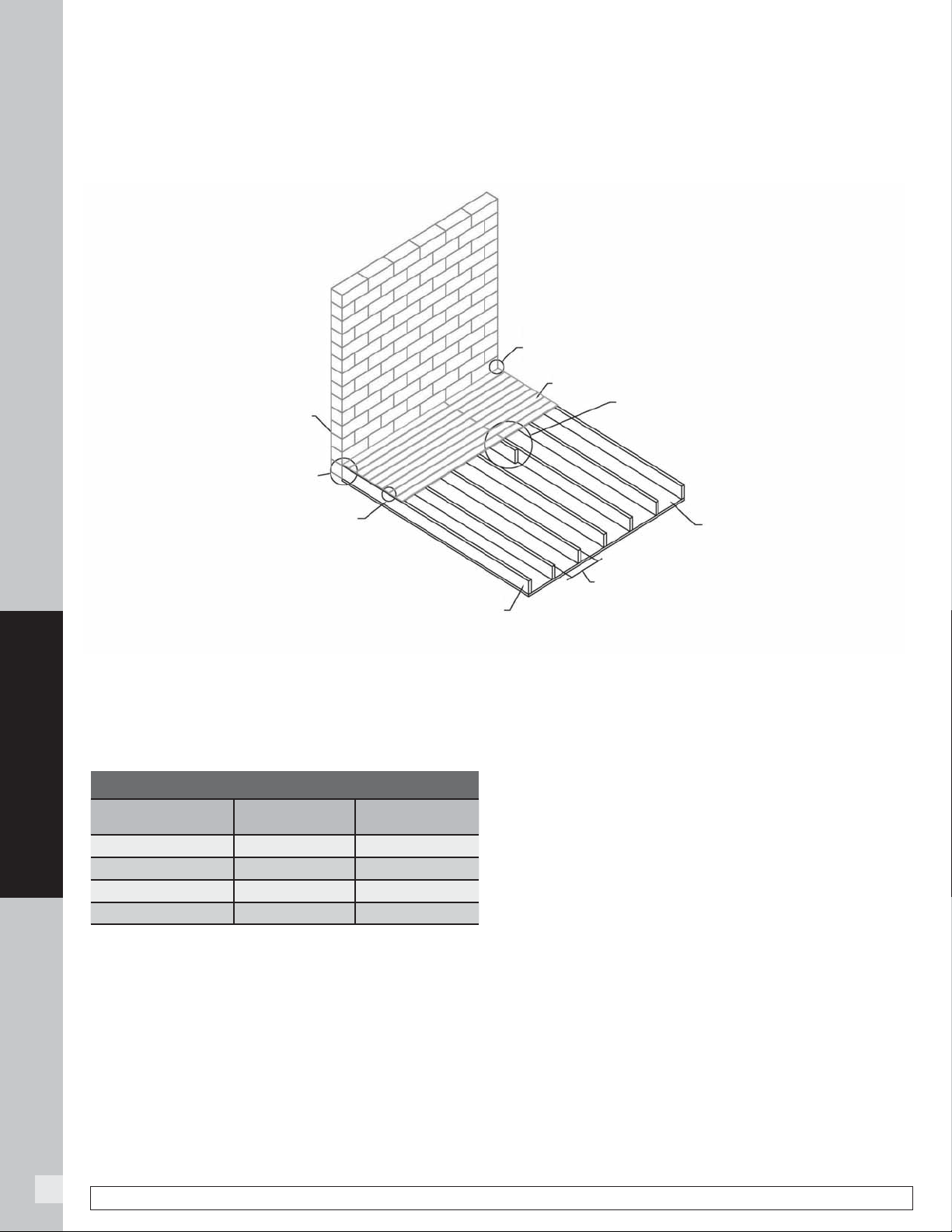
30
DECKING
ROOFTOP AND SLEEPER DECK SYSTEMS
NOTE: Construction methods are always improving. Please refer to www.trex.com for the most up-to-date installation requirements.
» It is recommended that building code approved
structural material be used as the supports.
» Gapping rules are required when installing Trex
decking:
TYPE OF GAP
Above 40°F
(4.5°C)
Below 40°F
(4.5°C)
Width-to-Width 1/4" (6 mm) 3/8" (10 mm)
End-to-End 1/8" (3 mm) 3/16" (5 mm)
End-to-Width 1/8" (3 mm) 3/16" (5 mm)
Abutting Solid Objects 1/4" (6 mm) 1/2" (13 mm)
» This system should not be allowed to fl oat; it must
be attached in a manner that secures the framing/
system.
» The sleeper system must be level and have no uneven
undulations. Any uneven areas of the substructure
will transfer to the Trex decking, resulting in uneven
decking.
» Trex, when used with a sleeper system, must be
supported below its entire length and if using in
a roofi ng application, the supports must run the
direction of the pitch of the roof to facilitate proper
drainage. Sleeper should be placed perpendicular to
the deck board orientation.
» For Commercial applications it is recommended
to consult local building code offi cial for specifi c
requirements.
» If installing decking at angle, decrease spans
4" (100 mm) for each of the above. (12" (305 mm)
for residential and 8" (204 mm) for commercial.)
» For sleeper systems where little debris (pine needles,
leaves, sand, dirt) can accumulate either between
or under deck boards, a minimum of 1-1/2" (38mm)
height is allowable. Trex recommended the use of
Trex Universal Hidden Fasteners or 2" Starborn
Cap-Tor
®
xd - Epoxy Coated screws. (NOTE: Trex
recommended composite decking screws are too long
when using 1-1/2" (38 mm) height as this will penetrate
through the sleeper.) For areas with the potential for
debris buildup, a minimum 3-1/2" (89 mm) or greater
height is recommended to allow the debris to be
removed along with the use of either Trex Universal
Hidden fasteners or any Trex recommended screws.
» ALWAYS consult your local building code authority
for proper details on roof and railing installation to the
roof structure if required.
» Any deviation from these recommendations could
result in the voiding of the Trex warranty.
A sleeper system is a substructure between a solid surface and Trex decking. Drainage, access, and airfl ow are
critical. Water must be able to fl ow through and away from the deck. For repairs and removal of debris, joist system
access may be necessary.
Solid Wall
Attach sleeper/bearer
joists to stable substructure
(i.e. wall and/or concrete
Gap decking width-to-width 1/4" (6 mm)–3/8" (10 mm)
depending on temperature at installation
(See note below for more information.)
Code-approved bearer substructure
Minimum 1- 1/2" (38 mm) thick and
1- 1/2" (38 mm) in height
(See note below for more information.)
Gap decking from solid object (i.e. wall)
1/4"–1/2" (6–13 mm) depending
on temperature at installation
(See note below for more information.)
Trex Decking
Where Trex decking is end-to-end and meets at a joist,
add a “nailer or sister joist” at the butt joint of the decking.
This will allow ends of each board to rest on a seperate
joist and be attached properly.
Flat level surface (i.e. concrete)
DO NOT ATTACH to unstable
substructure such as concrete
blocks or pavers setting in gravel,
sand, dirt, etc.
Residential = No greater than 16" (407 mm) on center
Commercial = No greater than 12" (305 mm) on center
(See note below for more information.)
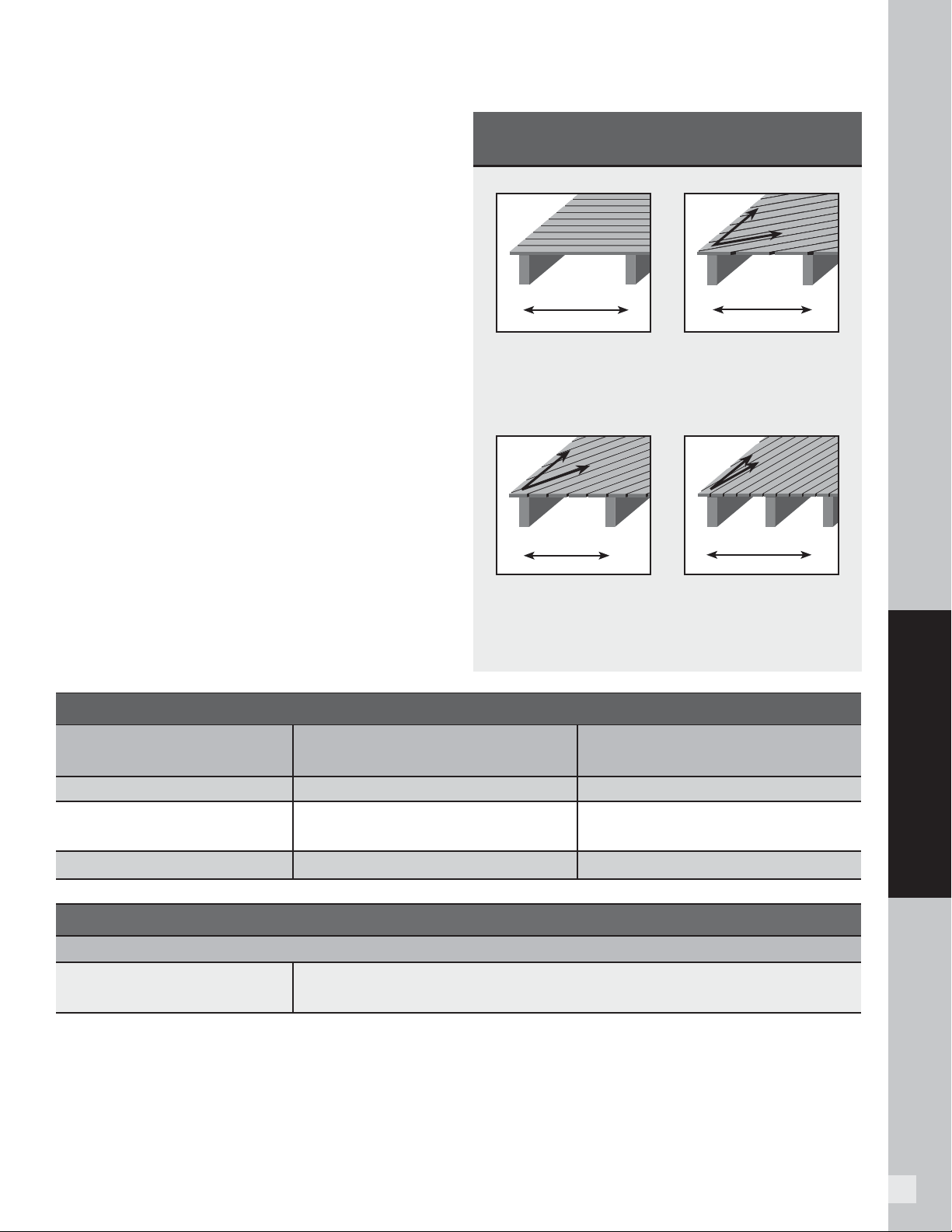
31
DECKING
At a 60° angle, maximum
joist spanning is 2"
(51 mm) less than listed in
the chart below.
60°
Perpendicular to joists.
See chart below.
90°
At a 45° angle, maximum
joist spanning is 4"
(102 mm) less than listed
in the chart below.
45°
At a 30° angle, maximum
joist spanning is 1/2 of
the distance listed in the
chart below.
30°
CODE COMPLIANCE
Joist Spanning for Decking
Trex
decking meets all applicable national model
building codes. The joists must be spaced on center
according to the chart below. Be sure that joists are
level and plumb. Trex decking must span at least three
joists. For heavy items such as hot tubs, planters,
etc., consult a local building engineer or inspector
for span recommendations. If you want to minimize
the appearance of joists through the spaces between
boards, paint the top of your joists black.
Code Listings
Trex complies with major model building codes and
has been evaluated by the International Code Council
evaluation service.
For a Safety Data Sheet (SDS), please visit www.trex.com
Trex Transcend and Trex Escapes
Trex Transcend and Trex Escapes are compliant with the
Wildland-Urban Interface, California State and San Diego
County fi re codes.
For more information, e-mail
question@www.trex.com
or call
1-800-BUY-TREX (1-800-289-8739).
ADJUST JOIST SPANNING TO ACCOMMODATE
ANGLED DECKING PATTERNS
TREX DECKING SPAN CHART (On Center)
Residential Decks, Light Duty Docks,
Residential/Day Care Playground
Commercial Decks,
Boardwalks and Marinas
Decking Loading 100 psf = 4.8 kN/m2 100 psf = 4.8 kN/m2 200 psf = 9.5 kN/m2
1" (25 mm) Boards (including Porch),
and .875" (22 mm) Select Boards
16" (406 mm) 16" (406 mm) 12" (305 mm)
2" x 6" (51 mm x 152 mm) Boards 24" (610 mm) 24" (610 mm) 16" (406 mm)
TREX RAILING SPAN CHART
Maximum Railing Span for all Applications
Transcend, Select railing, and
Signature railing
96" on center (2438 mm) for Transcend, 72" on center (1829 mm) for Select,
96" (2438 mm) clear span for Signature
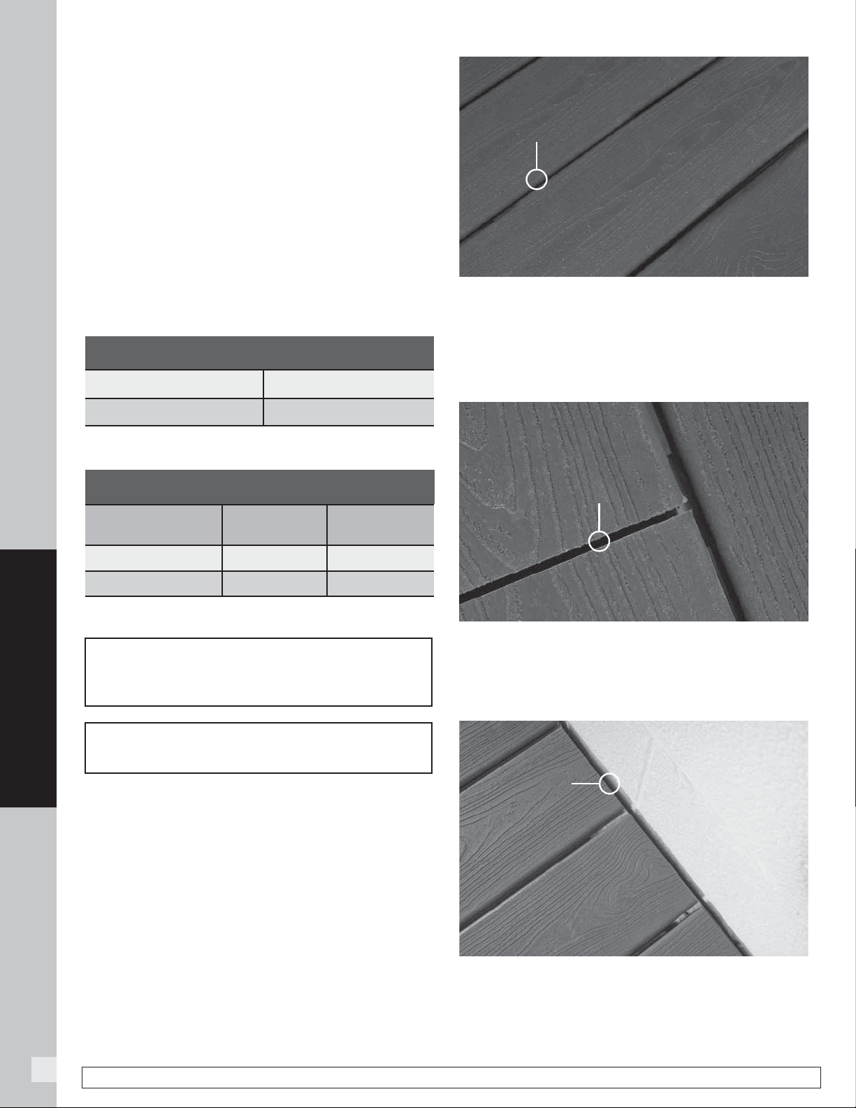
32
DECKING
GAPPING and OVERHANG
You must gap Trex decking, both end-to-end and
width-to-width. Gapping is necessary for drainage and
the slight thermal expansion and contraction of Trex
decking boards. Gapping also allows for the shrinkage
of the wood joist system.
» ALWAYS follow Trex-recommended gapping
guidelines.
» Maximum allowable perpendicular overhang for all
Trex decking is 1/2" (13 mm).
» All decks require air circulation to keep them dry and
looking good. To improve air fl ow, leave openings
under the decking or increase gapping to 3/8"
(10 mm).
End-to-End/End-to-Width
Gap Trex decking end-to-end, based upon the
temperature at installation. See chart at left.
For fastening tips, see pages 28–29.
Abutting Solid Objects
When decking is abutting a wall, you must also gap it
1/4"–1/2" (6–13 mm) depending on the temperature at
installation. See chart at left.
Width-to-Width
The minimum required width-to-width gapping is
1/4" (6 mm). This is allowed for both hot and cold
weather installations. For docks and heavily wooded
areas, Trex recommends a 3/8" (10 mm) gap as well.
No gapping should ever exceed 1/2" (13 mm).
1/4 "
(6 mm)
*Temperature at installation.
*Temperature at installation.
END-TO-END/END-TO-WIDTH AND ABUTTING GAP
End-to-End/
End-to-Width
Abutting Gap
Above 40°F* (4.5°C)* 1/4" (6 mm)
Below 40°F* (4.5°C)* 1/4" (6 mm)
WIDTH-TO-WIDTH GAP
1/8 " – 3/16"
(3 mm – 5 mm)
1/4 " – 1/2"
(6 mm – 13 mm)
Above 40°F* (4.5°C)* 1/8" (3 mm) 1/4" (6 mm)
Below 40°F* (4.5°C)* 3/16" (5 mm) 1/2" (13 mm)
When you use the recommended hidden
fasteners, the placement of the hidden fastener
establishes the designated gap size.
When installing fascia, gapping rules must
apply.
NOTE: Construction methods are always improving. Please refer to www.trex.com for the most up-to-date installation requirements.
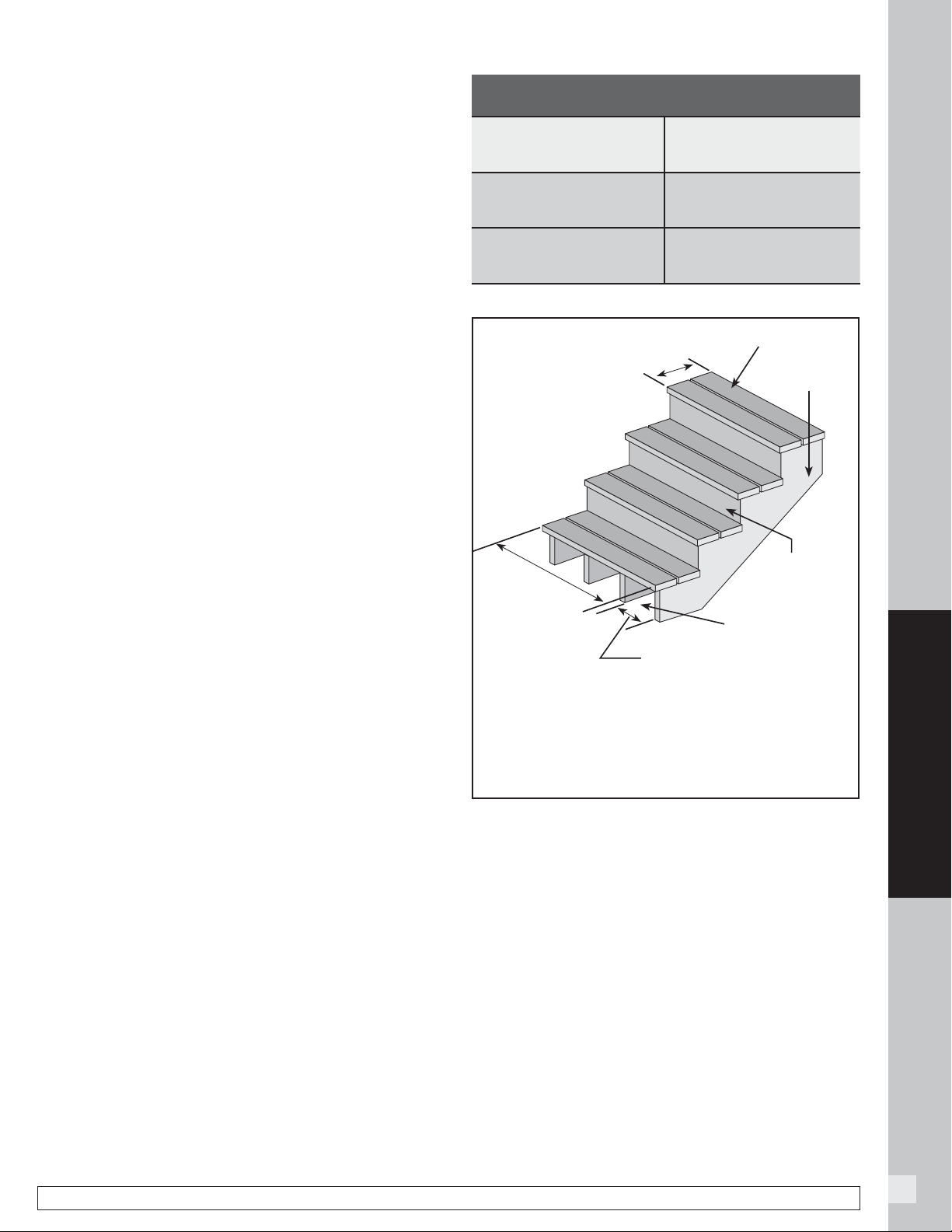
33
DECKING
NOTE: Construction methods are always improving. Please refer to www.trex.com for the most up-to-date installation requirements.
STAIRS
Stairway Detail
» Stair treads built with Trex meet requirements by
the major national building codes. Consult your local
municipality for specifi c requirements.
» Fasten stair treads continuously across at least four
stringers.
» See chart (at right) for center-to-center spacing of
profi les.
» Dress the sides of the stringers and risers with trim
or Trex fascia for a fi nished look.
» Most model building codes require the stair treads to
be constructed under the following requirements:
› Stairways must be at least 36" (914 mm) wide*
› Stair treads must be at least 11" (280 mm) deep
» Gapping between Trex boards on stair treads must
be 1/4"–3/8" (6 mm–10 mm).
» The overhang of the stair tread is not to exceed
3/4" (19 mm).
* For railings that are installed directly over stair treads, the stair
treads may need to be larger than 36" (914 mm) wide. Refer to local
building code regulations for details prior to installing stairs and
railings.
NOTE: Trex rails meet all major building codes for use
as a guardrail system. Local municipalities may require
a graspable handrail on stairways. Check with your local
building code offi cial for local requirements. See Trex
ADA Handrail System on pages 124–127.
MAXIMUM SPACING ON CENTER OF STAIR
STRINGER
Transcend & Enhance 1" X 6"
Actual dimensions - .94" X 5.5"
(24 mm x 140 mm)
12" (305 mm)
Select and Escapes 1" X 6"
Actual dimensions - .82" x
5.5"(20 mm x 140 mm)
9" (229 mm)
Transcend & Select 2" x 6"
Actual dimensions - 1.3" x 5.5"
(33 mm x 140 mm)
12" (305 mm)
Riser trim removed
for clarity
See chart above for spanning
requirements
36" (915 mm)
min. width –
4 stringers
required
Stair Tread
1" x 8"
(25 mm x 203 mm)
Riser
11" (280 mm)
min. depth
Stringer
NOTE: 4 STRINGERS ARE REQUIRED IF 12" (305 MM) SPAN;
5 STRINGERS ARE REQUIRED IF 9" (229 MM) SPAN.
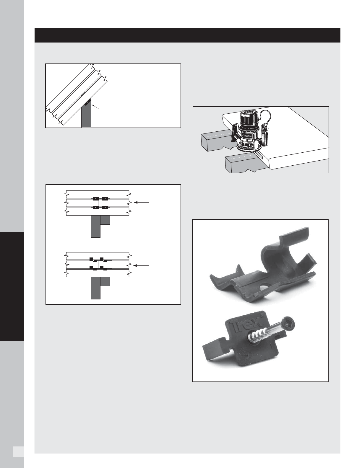
34
DECKING
Installing Angled Deck Boards in Corners
ALWAYS start in corner with a small triangular piece
of decking at 45° and work outwards. Install Trex
Hideaway Hidden Fasteners 1/2" (13 mm) off center
to keep fastener screws in middle of joists.
How to Butt Seams
1. Install 10"–12" (254 mm–305 mm) framing
boards along joists where seams will butt.
2. Place additional fasteners on the adjacent board
over the joist and framing boards where the seam
will be.
3. Put the fi rst board of the seam in place and
secure with fastener.
4. Following proper gapping for abutting boards (see
page 32), place second board in proper location
and secure with fastener.
5. Place second set of fasteners on each side of butt
seam for each board.
Routing Square Edge Boards for Trex
Hideaway Hidden Fasteners
NOTE: The following Trex Square Edge decking
boards (Trex Transcend, Trex Enhance, Trex
Escapes, Trex Accents, and Trex Select), either
1x6 or 2x6, can be routed.
Using a Trex router bit/groove cutter available at
your local Trex dealer:
1. Rout from bottom side of board.
2. Rout the entire length of the board, or at every
intersection where board is over support joists.
NOTE: Hidden Fasteners MUST be used at every
joist.
Refer to www.trex.com for technical bulletin on how
to install connector clips with Trex Transcend, Enhance
and Select decking products.
TIPS FOR INSTALLING A TREX HIDEAWAY
®
HIDDEN FASTENING SYSTEM
For Universal
and Stainless
Steel (Universal
shown here)
Shift 1/2"
(13 mm)
Universal
Stainless Steel
Decking
board
Decking
board
Connector Clip
(stainless steel)
Universal Fastener
DECKING BOARD
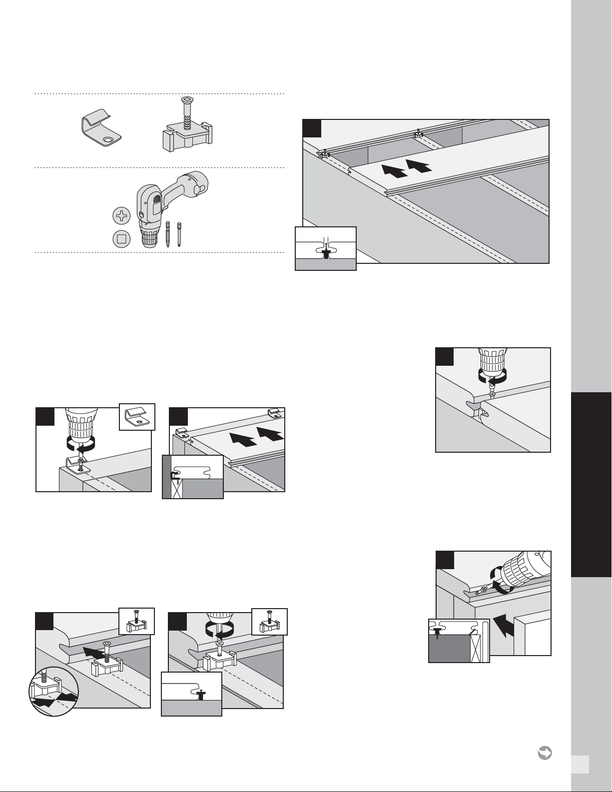
35
HOW TO INSTALL DECKING
PARTS
TOOLS NEEDED
NOTE: Maximum spacing of deck boards using
Hideaway system is 16" (406 mm) on center. Fasteners
provide 1/4" (6 mm) gap when installed correctly.
TIP: If installing in localities prone to large temperature
shifts within a 24-hour period, when installing Trex Universal
Hidden Fasteners, also predrill and toenail a screw (use
same screw used in hidden fasteners) at an angle in groove
at both ends (at least 1” from board end) and center of each
board.
Installing Start Clips and First Board
1. Install start clips on edge of ledger board, centered
on each joist. Secure clips with screws.
2. Push grooved edge of deck board into start clips.
Important: First board MUST be straight and well
secured.
Installing Universal Fasteners
3. Insert fastener into grooved edge of deck board.
4. Align screw hole in fastener with center of joist.
Continue along the length of the board at every joist.
NOTE: Screw only halfway down. DO NOT fully tighten.
Installing Second Board
5. Slide second board into place, making sure
fasteners fi t into groove. Install the next universal
fastener on the other side of the second board in
the same manner as Steps 3 and 4. DO NOT fully
tighten the screw.
Complete Installation
6. Tighten screws on
fasteners in fi rst row.
Proceed with Steps
3 through 5, tightening
down each row after
board that follows is in
place. Be sure to use a
long #1 square bit.
Installing Last Board
Option 1:
NOTE: If boards are slightly bowed up, you can use this
option to draw boards down on the fi nal joist. This can
also help eliminate overall movement of the boards in
areas prone to wide temperature changes.
Using Fascia Board
7a. Pre-drill pilot holes at an
angle through grooved
edge of deck board into
ledger board. Install
2-1/2" (64 mm) screws
through pilot holes to
secure. Attach a fascia
board fl ush with deck
surface.
1
2
2
3
1
1
2
4
5
1/4" (6 mm)
2
6
1
2
7a
Start clip
Universal fastener
HOW TO INSTALL TREX HIDEAWAY UNIVERSAL HIDDEN FASTENERS
(TREX TRANSCEND, ENHANCE, SELECT, AND ESCAPES)
NOTE: See page 36 for additional instructions if installing Escapes.
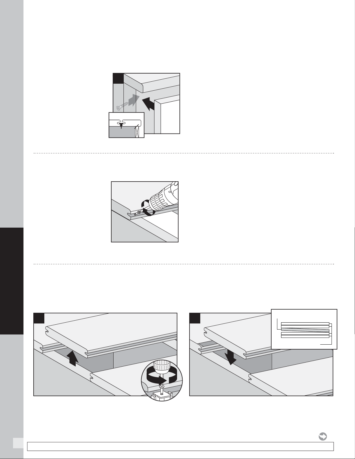
36
Option 2:
With Deck Board Overhang (Using Square Edge
Board as Final Board)
7b. Pre-drill pilot holes at 45°
angle from below deck
surface through rim
joist. Seat last board into
fasteners overhanging
rim joist. Secure board
with 2-1/2" (64 mm)
screws using pilot holes.
Position fascia board
below overhanging deck
board.
Option 3:
Face Screwing Both Decking and Fascia
8. Both decking and fascia can be attached using
approved face screw fasteners.
HOW TO INSTALL DECKING
Universal Fasteners
1. Remove screws from fasteners on both sides of
board to be replaced and remove board.
2. Angle new board to place. See inset box (above).
2
1
1
2
New board at an angle
Existing Deck
HOW TO INSTALL ESCAPES BOARDS
WITH TREX HIDEAWAY UNIVERSAL HIDDEN FASTENERS
1. Follow Steps 1–2 for
installing start clips
and fi rst board.
See page 35.
2. At both ends and
center of fi rst board,
toenail screw (provided
with Hideaway
universal hidden
fasteners), at an angle
through grooved edge of deck board.
3. Follow Steps 3–4 for installing universal fasteners.
See page 35.
4. For every consecutive board installed, toenail screw
at an angle through grooved edge of deckboard as
stated in Step 3.
5. Follow remaining steps for completing installation
and installing last board. See page 35.
HOW TO REPLACE TREX BOARDS
INSTALLED WITH TREX HIDEAWAY UNIVERSAL FASTENERS (TREX TRANSCEND,
ENHANCE, SELECT, AND ESCAPES)
1
2
7b
HOW TO INSTALL TREX HIDEAWAY UNIVERSAL HIDDEN
FASTENERS/
CONTINUED
NOTE: Construction methods are always improving. Please refer to www.trex.com for the most up-to-date installation requirements.
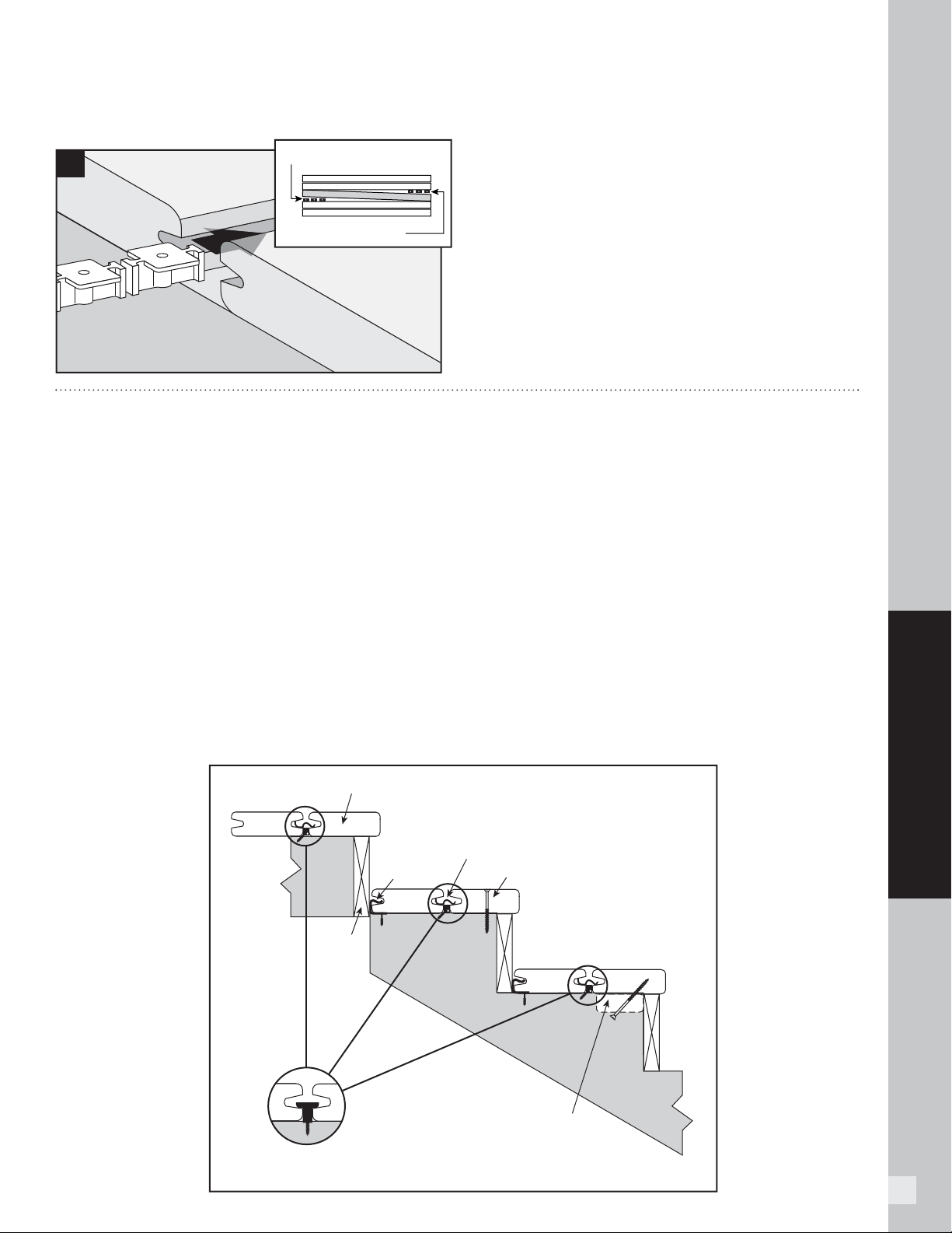
37
HOW TO INSTALL DECKING
HOW TO INSTALL STAIR TREADS
(TREX TRANSCEND, ENHANCE, SELECT, AND ESCAPES)
Installation Options
NOTE: For best results, use square edge decking
and manually route sides that will be used to attach
hidden fasteners.
Option 1:
Face Screw
1. Install start clips against riser on each step.
2. Install fi rst board. Follow steps on page 35.
3. Install second board. Follow steps on page 35.
4. Secure with screws from top of second board into
stringer boards.
Option 2:
Using 2" x 4" (51 mm x 102 mm) Wood
Support Blocks
1. Install start clips against riser on each stair tread.
2. Install fi rst board. Follow steps on page 35.
3. Attach 2" x 4" (51 mm x 102 mm) blocks between
stringers.
4. Pre-drill holes up through blocks.
5. Install second board. Follow steps on page 35.
6. Secure with screws from bottom through blocks
and into stair treads.
Decking board
Option 1
Face Screw
Connector Clip (Stainless Steel Fastener)
Start Clip
Deck Frame
Stringer
Option 2
Riser
3
Insert Fasteners
Insert Fasteners
HOW TO REPLACE TREX BOARDS/CONTINUED
INSTALLED WITH TREX HIDEAWAY UNIVERSAL FASTENERS (TREX TRANSCEND,
ENHANCE, SELECT, AND ESCAPES)
Universal Fasteners
3. Slide a fastener for each joist into board grooves
from both ends of the board.
NOTE: You may have to loosen adjacent boards to slide
fasteners into position.
4. Position replacement board and secure fasteners
on center of each joist.
Pressure-treated 2x4
fastened to stringer
Universal fasteners may also be
used to join the decking boards
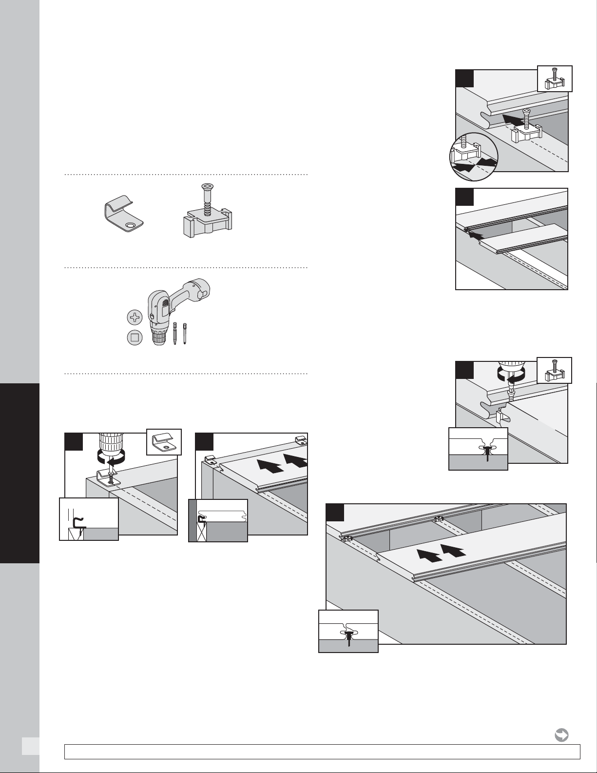
38
HOW TO INSTALL DECKING
HOW TO INSTALL TREX TRANSCEND PORCH BOARDS
NOTE: When installing Trex Porch boards in a
non-covered environment, the porch structure should be
slightly sloped to help allow for proper drainage. Joists
should be sloped 1/8" (3 mm) per foot away from the
house to facilitate drainage. Refer to your local building
code offi cial for recommendations BEFORE building
substructure. When installing Trex Porch boards under
cover of a roof, no slope is required.
PARTS
TOOLS NEEDED
NOTE: Refer to page 31 for proper joist spanning
requirements.
Installing Start Clips and First Porch Board
1. Measure 3/8" (10 mm) off of edge of ledger board,
and install start clip onto ledger board, centered on
each joist. Secure clips with screws.
2. Push grooved edge (longer edge side) of porch
fl oorboard into start clips. Important: First board
MUST be straight and well secured.
Installing Trex
Hideaway Universal
Hidden Fasteners
3. Insert fastener into
grooved edge (shorter
edge side) of porch
board, making sure
to align screw hole in
fastener with center of
each joist.
4. IT IS SUGGESTED
THAT IN ORDER TO
KEEP THE FASTENER
STRAIGHT AND
SECURE, CUT AN 18
"
(457 mm) PIECE
OF PORCH SCRAP
BOARD AND USE
THIS AS AN AID (USE
SMALLER LIP SIDE)
TO HELP HOLD THE HIDDEN FASTENER DOWN
BEFORE SCREWING THIS IN. This will help make
sure the fastener stays fully straight for remaining
boards to be attached.
5. Fully tighten (but
DO NOT over tighten)
the screw into each
joist while keeping
the scrap board in
fi rm place against the
hidden fastener.
Installing Second Porch Board
6. Slide second porch board into place, making
sure fasteners fi t into groove. Install the next universal
fastener on the other side of the second porch board
in the same manner as Steps 3–5.
1
3/8" (10 mm)
2
2
3
1
1
2
2
Scrap board
5
4
6
Start clip
Universal fastener
NOTE: Construction methods are always improving. Please refer to www.trex.com for the most up-to-date installation requirements.
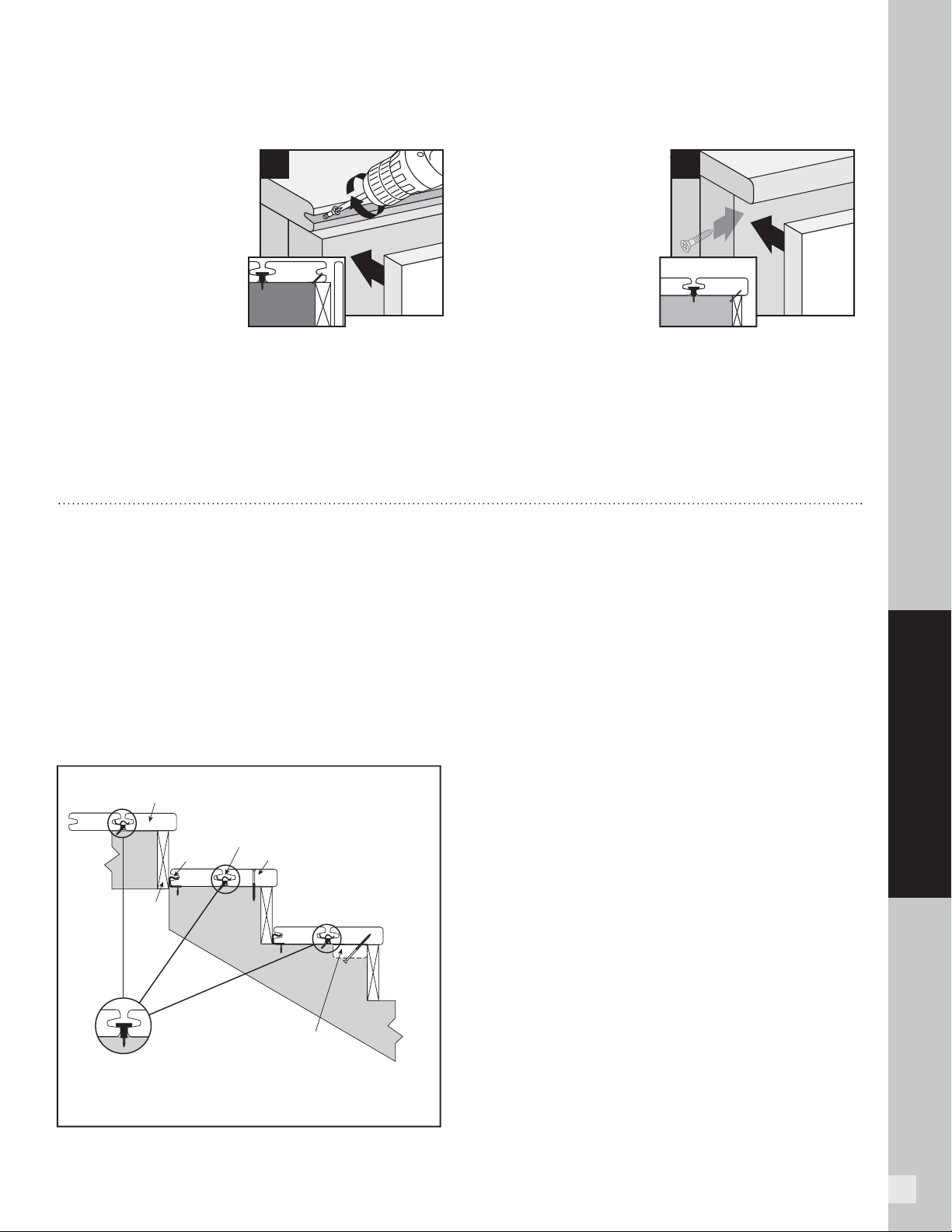
39
HOW TO INSTALL DECKING
Installing Last Porch board
Option 1:
Using Fascia Board
7a. Pre-drill pilot holes
at an angle through
grooved edge of porch
board into ledger
board. Install 2-1/2"
(64 mm) screws
through pilot holes to
secure. Attach fascia
board fl ush with porch
board surface.
NOTE: In most cases there will be additional screws
that come with the Trex Hideaway Universal Hidden
Fasteners. These screws can also be used for
attachment of the last board in the method shown
above.
Option 2:
With Porch Board
Overhang
NOTE: This side of porch
board will have to be cut
fl ush to not show grooves.
Note that color of porch
board will be slightly
different at cut edge.
7b. Pre-drill pilot holes at 45° angle from below deck
surface through rim joist. Seat last porch board into
fasteners overhanging rim joist. Secure porch board
with 2-1/2" (64 mm) screws using pilot holes. Position
fascia board below overhanging porch board.
HOW TO INSTALL TREX TRANSCEND PORCH BOARDS/CONTINUED
1
2
7b
1
2
7a
HOW TO INSTALL PORCH STAIR TREADS
Option 1: Using Hidden Fasteners and Face
Screwing
1. Install start clips against riser on each step.
2. Install fi rst board. Follow steps on page 35.
3. Install second board. Follow steps on page 35.
4. Secure with screws from top of second board into
stringer boards.
Option 2: Using Hidden Fasteners and 2" x 4"
(51 mm x 102 mm) Wood Support Blocks
1. Install start clips against riser on each stair tread.
Follow steps on page 35.
2. Install fi rst board. Follow steps on page 35.
3. Attach 2" x 4" (51 mm x 102 mm) blocks between
stringers.
4. Pre-drill holes up through blocks.
5. Install second board. Follow steps on page 35.
6. Secure with screws from bottom through blocks
and into stair treads.
NOTE: Use square edge composite decking boards and manually route these on one side to allow for
use with hidden fasteners.
Decking board
Option 1
Face screw
Start clip
Deck
frame
Stringer
Option 2
Riser
Pressure-treated 2x4
fastened to stringer
Connector Clip (Stainless Steel Fastener)
Universal fasteners
may also be used
to join the decking
boards
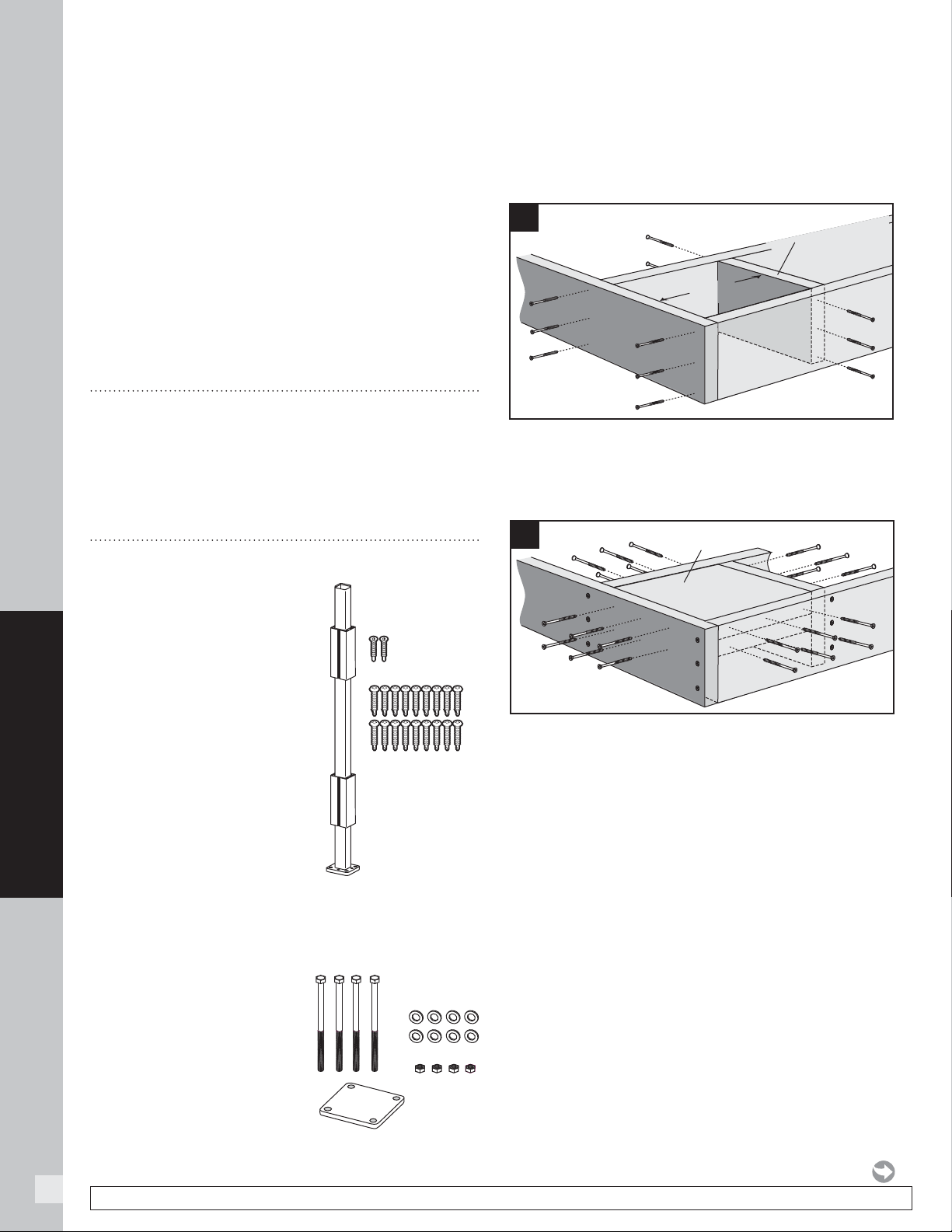
40
HOW TO INSTALL DECKING
IMPORTANT NOTES:
» EACH POST MUST BE ATTACHED AS SHOWN
TO ENSURE A CODE-COMPLIANT AND SAFE
INSTALLATION.
» ALWAYS REFER TO YOUR LOCAL BUILDING CODE OFFICIAL PRIOR TO
INSTALLING ANY RAILING SYSTEM TO ENSURE ALL CODE AND SAFETY
REQUIREMENTS ARE MET. TREX CANNOT BE HELD RESPONSIBLE FOR
IMPROPER OR NON-RECOMMENDED INSTALLATIONS.
» WHEN INSTALLING TREX POST MOUNTS ON ACQ OR CCA SURFACES,
USE AN APPROPRIATE ISOLATION BARRIER BETWEEN POST AND
SURFACE (CONTACT LOCAL BUILDING CODE OFFICIAL IF NEEDED).
» ENSURE THAT CORRECT SKU HARDWARE IS ORDERED FOR THE TYPE
OF RAILING BEING INSTALLED.
» CANNOT BE USED WITH TREX TRANSCEND COCKTAIL RAILING.
» See page 53 for sku information.
TOOLS AND MATERIALS NEEDED
»
Drill and/or screw gun
»
1/2" (1.3 cm) drill bit for wood
»
Blocking – 2" x 8" (5.1 cm x 20.3 cm)
pressure-treated Southern Yellow Pine or equivalent
»
Qty: 36 (per post) – 3" (7.6 cm) pressure-treated
compatible wood screws
PARTS
» (1) Post mount
» (2) Guide blocks
» (18) #8-15 x 1-1/4" (3.2 cm)
Self-tapping screws
» (2) 10 x 1" (2.5 cm)
Self-tapping screws
SKU ALPOSTHWDECK (this SKU SOLD SEPARATELY
and must be used for code-approved applications)
» (4) 3/8" x 6" (1 cm x
15.2 cm) Hex cap bolts
» (1) Back plate
» (8) Flat washers
» (4) Hex nuts
How to Install Post
Mounts on Pressure-
Treated Wood Framing
Corner Post Installation
1. Install 2" x 8" (5.1 cm x 20.3 cm) cross bracing
frame in between joists at 7-1/4" (18.4 cm). Attach
a total of twelve 3" (7.6 cm) pressure-treated
compatible screws (not provided).
2. Install two 2" x 8" (5.1 cm x 20.3 cm) boards as
blocking under post location. Securely attach
blocking using a total of twenty-four
3
"
(7.6 cm)
pressure-treated compatible screws (not provided).
NOTE: TO ENSURE THE BLOCKING IS FULLY SECURE,
USE THE AMOUNT OF SCREWS INDICATED ABOVE.
TIP: USE TWO ADDITIONAL SCREWS TO “SANDWICH”
BLOCKING BOARDS TOGETHER FOR EASIER
ATTACHMENT TO FR AMING.
LOCATION AND INSTALLATION OF SURFACE MOUNT POST – DECKING
7-1/4"
(18.4 cm)
7-1/4
"
(18.4 cm)
2" x 8" Pressure-treated
Cross bracing frame
1
2
Blocking
boards
NOTE: Construction methods are always improving. Please refer to www.trex.com for the most up-to-date installation requirements.
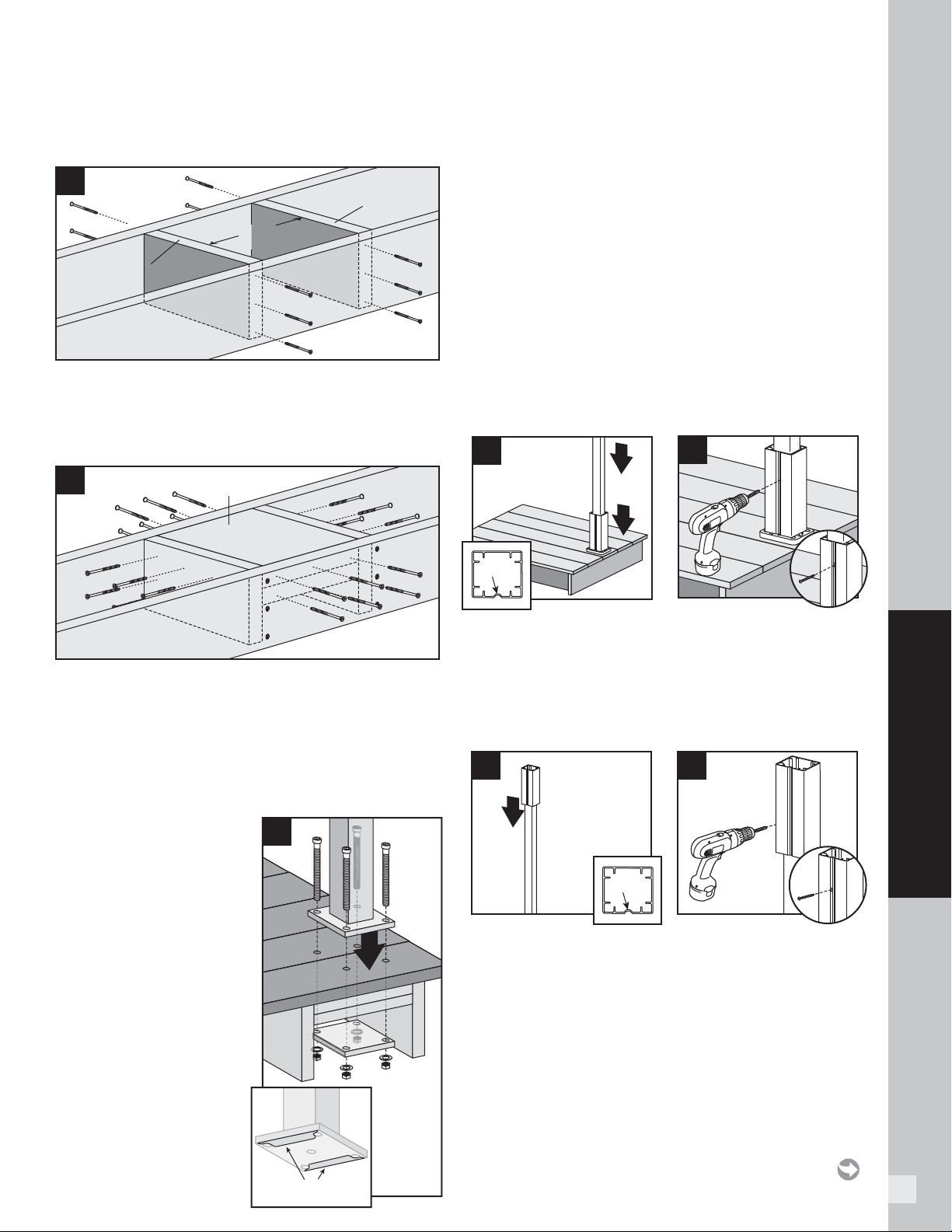
41
HOW TO INSTALL DECKING
LOCATION AND INSTALLATION OF SURFACE MOUNT POST – DECKING/
CONTINUED
Line Post Installation
3. Install two 2
"
x 8
"
(5.1 cm x 20.3 cm) cross bracing
frames in between joists at 7-1/4
"
(18.4 cm). Attach a
total of twelve 3
"
(7.6 cm) pressure-treated compatible
screws (not provided).
4. Install two 2
"
x 8
"
(5.1 cm x 20.3 cm) boards as
blocking under post location. Securely attach
blocking using a total of twenty-four 3
"
(7.6 cm)
pressure-treated compatible screws (not provided).
5. NOTE: RIM JOIST REMOVED TO SHOW PROPER
ATTACHMENT OF HARDWARE.
Insert the (2)
stainless steel barrier
strips under the
mounting bolt holes.
Use composite shims
or similar material
(not provided) if posts
are not plumb. Ensure
that post is placed
on decking surface
so that it clears the
rim joist and there
is enough clearance
on the underside
blocking for the back
plate to be installed.
Attach posts using four 3/8" x 6" (1 cm x 15.2 cm)
hex cap bolts, washers, and nuts, along with aluminum
back plate on underside of blocking. If the project
requires IRC compliance, this back plate MUST
be installed under the decking to ensure this will
meet code compliance. Reference SKU part number
ALPOSTHWDECK for required hardware and aluminum
plate. (Consult local code offi cial for more information
on IRC Compliance.)
Install Guide Blocks
NOTE: Pre-drilling is not required but is optional for
attachment of guide blocks to post. Use a drill bit slightly
smaller in size than that of screw being installed.
6. Place or rest bottom aluminum guide block on
bottom of post. Place guide on post so that notch is
on a side that does not require railing to be attached.
7. Attach bottom guide block using one 10 x 1” self-
tapping screw (provided) in notch to lock guide block
onto post.
8. Location of top guide block will vary slightly based on
type and height of railing being installed. Determine
this measurement and place top guide block in
location where top bracket for desired railing would
be approximately on center of the top railing bracket
location.
9. Attach top guide block using one 10 x 1” self-tapping
screw (provided) in notch to lock guide block onto
post.
4
Blocking
boards
5
barrierbarrier
7-1/4
"
(18.4 cm)
7-1/4"
(18.4 cm)
3
Cross bracing
frame
Cross bracing
frame
6
notch
8
notch
7
9
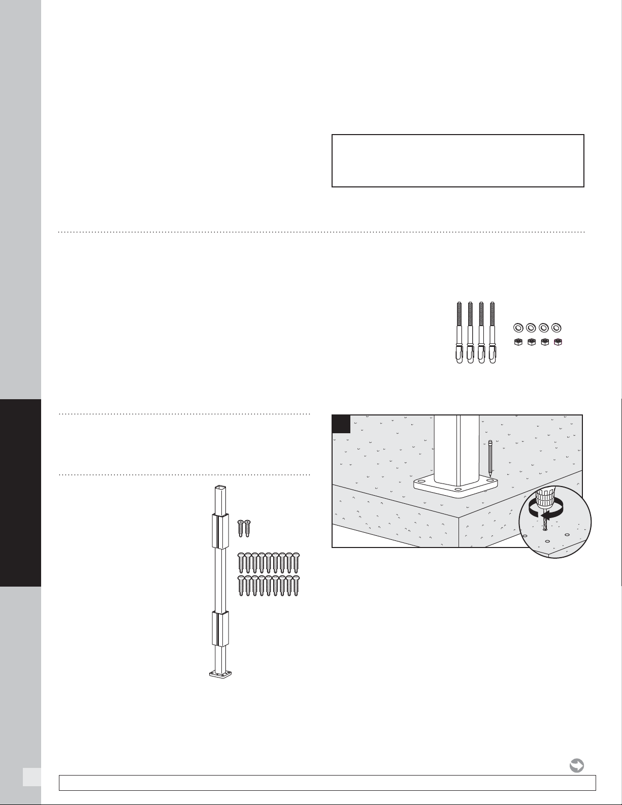
42
HOW TO INSTALL DECKING
NOTE: Construction methods are always improving. Please refer to www.trex.com for the most up-to-date installation requirements.
LOCATION AND INSTALLATION OF SURFACE MOUNT POST – DECKING/
CONTINUED
Install Railing System of Choice
NOTES:
» Quantity of 18 self-tapping screws are provided to
cover all types of Trex railing bracket installations
(Transcend, Signature [formerly Reveal], and Select).
Thus depending on the type railing being installed, you
may have screws that are not used.
» If using 6x6 post sleeves, attach designated railing
brackets using #8-15 x 1-3/4" (4.4 cm) 316 stainless
steel self-tapping screws (
not provided
).
» Pre-drilling is not required but is optional for
attachment of brackets to guide blocks. Use a drill
bit slightly smaller in size than that of screw being
installed.
NOTE: If installing Trex DeckLighting on the posts,
drill hole through support blocks to allow wiring for
lights to be below the surface of the decking.
LOCATION AND INSTALLATION OF IRC-APPROVED POST MOUNTS – CONCRETE
IMPORTANT NOTES:
» INSTALLATION SHOWN HERE IS FOR IRC APPROVED
APPLICATIONS ONLY.
» MAKE SURE CONCRETE IS LEVEL BEFORE INSTALLING POSTS.
» ALWAYS REFER TO YOUR LOCAL BUILDING CODE OFFICIAL
PRIOR TO INSTALLING ANY RAILING SYSTEM TO ENSURE ALL
CODE AND SAFETY REQUIREMENTS ARE MET. TREX CANNOT BE
HELD RESPONSIBLE FOR IMPROPER OR NON-RECOMMENDED
INSTALLATIONS.
» CANNOT BE USED WITH TREX TRANSCEND COCKTAIL RAILING.
» See page 53
for sku information.
TOOLS NEEDED
»
Hammer
»
Drill and/or screw gun
»
3/8" (10 mm) drill bit for concrete
PARTS
» (1) Post mount
» (2) Guide blocks
» (18) #8-15 x 1-1/4" (32 mm)
Self-tapping screws
» (2) 10 x 1" (25 mm)
Self-tapping screws
SKU ALPOSTHWCONC
(this SKU SOLD SEPARATELY)
» (4) 3/8" x 3-3/4"
(10 mm x 95 mm)
Expansion anchor
» (4) Flat washers
» (4) Hex nuts
Pre-drill Holes
1. Using post as a template, mark locations of the four
holes and drill into concrete at least 2-5/8 " (66.7 mm)
using a 3/8 " (10 mm) masonry bit.
NOTE: You can either set drill bit to correct depth on
drill or mark drill bit with tape at required dimension to
ensure all holes are drilled at the correct depth.
1
3/8"
(10 mm)
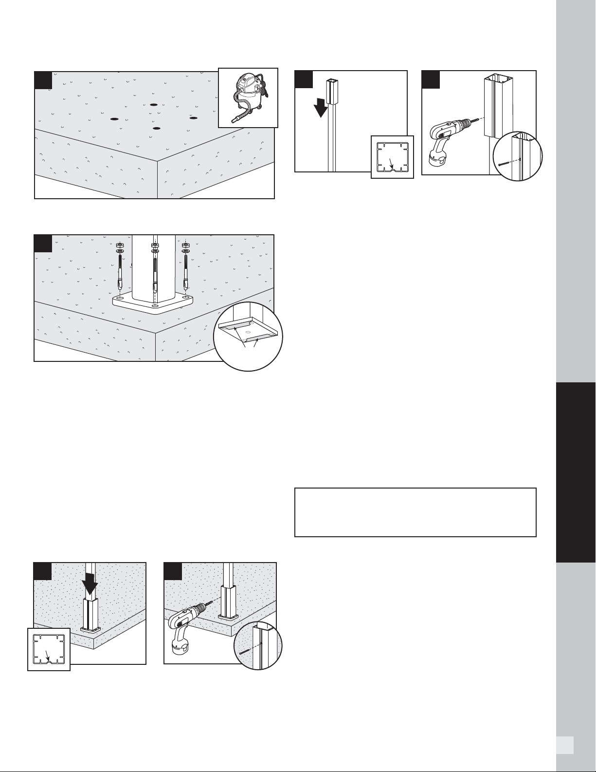
43
HOW TO INSTALL DECKING
2. Clean out holes to remove all concrete dust.
3. Insert the (2) stainless steel barrier stripes under
the mounting bolt holes. Use appropriate shims if
posts are not plumb. Secure post mount with the
four expansion anchors, washers and nuts.
NOTE: When using hammer to tap anchors in place,
keep the threaded nut at the top of the anchor in order to
not damage the threads.
NOTE: Recommended torque for anchors is 20 ft-lbs.
Install Guide Blocks
NOTE: Pre-drilling is not required but is optional for
attachment of guide blocks to post. Use a drill bit slightly
smaller in size than that of screw being installed.
4. Place or rest bottom aluminum guide block on
bottom of post. Place guide on post so that notch is
on a side that does not require railing to be attached.
5. Attach bottom guide block using one 10 x 1" (25 mm)
self-tapping screw (provided) in notch to lock guide
block onto post.
6. Location of top guide block will vary slightly based
on type and height of railing being installed.
Determine this measurement and place top guide
block in location where top bracket for desired
railing would be approximately on center of the top
railing bracket location.
7. Attach top guide block using one 10 x 1" (25 mm)
self-tapping screw (provided) in notch to lock guide
block onto post.
Install Railing System of Choice
IMPORTANT NOTES:
» Quantity of 18 self-tapping screws are provided to
cover all types of Trex railing bracket installations
(Transcend, Signature [formerly Reveal], and Select).
Thus depending on the type railing being installed, you
may have screws that are not used.
» Pre-drilling IS REQUIRED when attaching brackets to
designated posts. Use a 9/64" (3.6 mm) drill bit to pre-
drill at specifi ed locations according to instructions
provided with railing kits.
» If using 6x6 post sleeves, attach designated railing
brackets using #8-15 x 1-3/4” (44 mm) 316 stainless
steel self-tapping screws (
not provided
).
NOTE: If installing Trex lighting on the posts,
drill hole through support blocks to allow wiring for
lights to be below the surface of the decking.
2
3
BarrierBarrier
LOCATION AND INSTALLATION OF POST MOUNTS – CONCRETE/CONTINUED
6
notch
7
5
4
notch
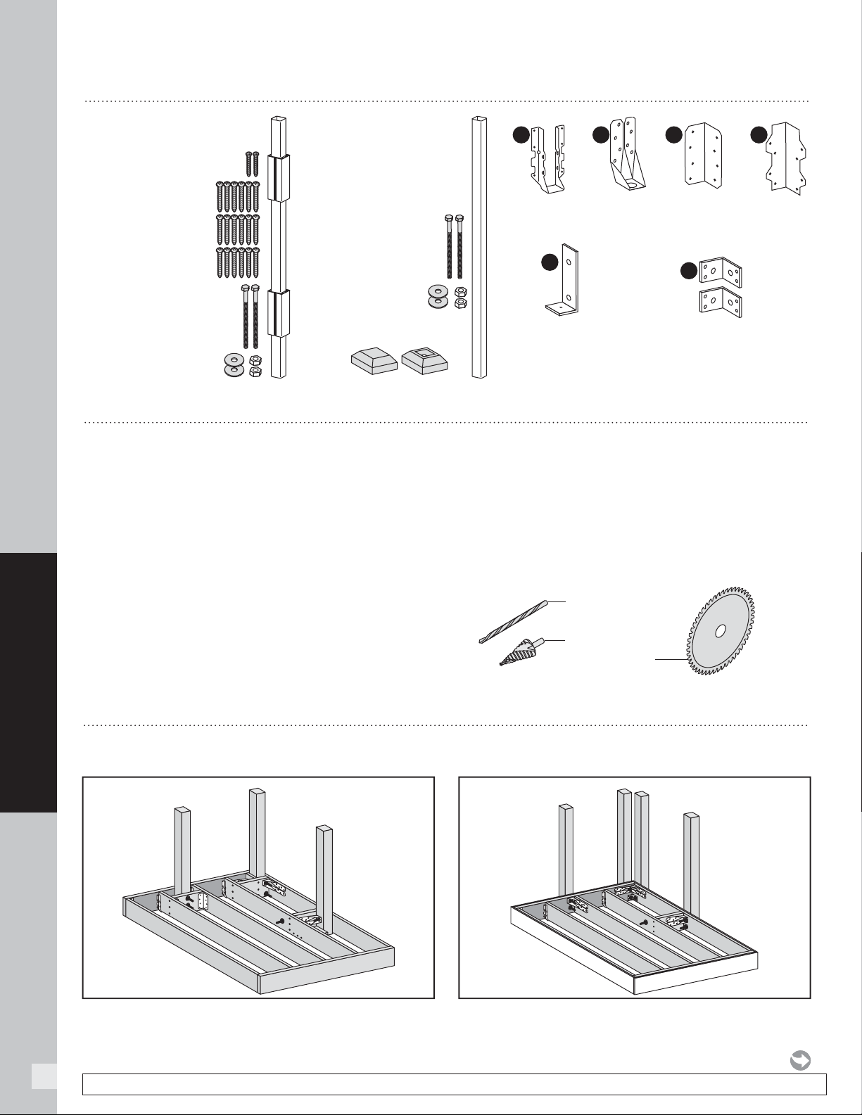
44
HOW TO INSTALL DECKING
NOTE: Construction methods are always improving. Please refer to www.trex.com for the most up-to-date installation requirements.
HOW TO INSTALL JOIST MOUNT POSTS
Wood Frame (Inside Mount) Overview Wood Frame (Fascia Mount) Overview
GENERAL GUIDELINES
Trex Fascia Mount
Bracket Kit (Wood)
SKU - XXFMNTWOOD
F
Trex Fascia Mount Corner
Bracket Kit (Brackets, Bolts,
Nuts, Washers, & Screws)
SKU - XXCORNERFMNTWOOD
G
HELPFUL TOOLS
9/16" x 6" (14 mm x 152 mm)
or longer Drill Bit
Non-ferrous
Metal Cutting Blade
1/2" (13 mm)
Step Bit
Simpson
ML26Z**
(or similar)
Simpson
DTT2Z**
Simpson
L70Z**
(or similar)
Simpson
LUS28Z**
(or similar)
B C D E
Joist Mount Post for
Trex Composite Post Sleeve
SKU CPJMNTPOST63
» (1) Joist Mount Post
» (2) Guide blocks
» (2) 10 x 1" (2.5 cm)
Self-tapping screws
» (18) #8-15 x 1-1/4"
(3.2 cm)Self-tapping
screws
» (2) 1/2" x 8" Bolts,
Washers, & Nuts
Trex Joist Mount Post
for Trex Signature Railing
SKU XXJMNTPOST63
XX denotes color: (BK-Black,
BZ-Bronze, WT-White)
» (1) Joist Mount Post
» (2) 1/2" x 8" Bolts,
Washers, & Nuts*
» (1) Post Cap
» (1) Post Skirt
* Note: bolt heads,
washers, and nuts
are color matched
to joist mount post color
NOTE: To allow fascia to sit fl at against framing, route/trim out back side
of fascia to allow for fi t over bolt locations
.
NOTES:
»
Trex fascia should be installed prior to installing any outside joist
post mounts.
»
Can only be used with Signature 6' or less railing spans.
» Code-Approved Joist Mount Post Applications:
- 30" or less deck height - Code approval not
applicable
- IRC Compliant - Yes
- IBC Compliant - No
»
Minimum framing is 2"x 8" (51 mm x 203 mm)
(ensure all structural brackets are sized appropriately
for framing).
» Follow all structural bracket manufacturer's guidelines
for fastener selection and corrosion protection
requirements.
» Maximum OC framing is 16" (406 mm).
» This post is designed to cut-to-length and will
accommodate up to 42" (1067 mm) stair railing on
2" x 12" (51 mm x 305 mm) framing.
» Included template works for most, but not all,
applications. Review instructions carefully prior to
drilling holes, making sure to center holes on post.
» **
Simpson structural brackets are not included with
joist mount posts and must be purchased seperately.
XX denotes color BK-Black, BZ-Bronze, WT-White
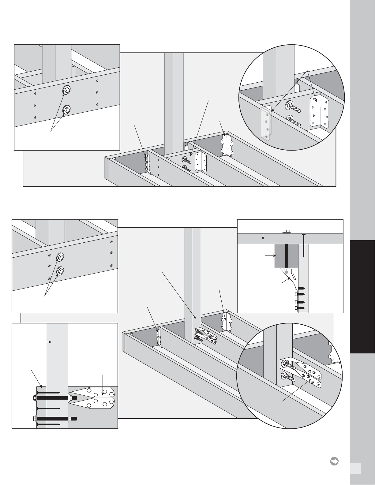
45
HOW TO INSTALL DECKING
INSIDE MOUNT (FRONT RIM PLATE - BETWEEN JOISTS WITH BLOCKING)
Simpson
L70Z
Trex Bolts 1/2" x 8" (13 mm x 203 mm),
Nuts, and Washers
Simpson
LUS28Z
Simpson
ML26Z
Blocking
2"x 8"
(51 mm x 203 mm)
INSIDE MOUNT (FRONT RIM PLATE - NEXT TO JOIST)
Simpson
L70Z
Simpson
DTT2Z
Simpson
DTT2Z
Trex Bolts 1/2" x 8" (13 mm x 203 mm),
Nuts, and Washers
TOP VIEW
SIDE VIEW
Post
Front Rim Joist
Front Rim
Joist
Simpson
LUS28Z
Post
Simpson
DTT2Z
NOTE: If a joist hanger
is in this location,
it must be removed
so post mount will fit
properly.
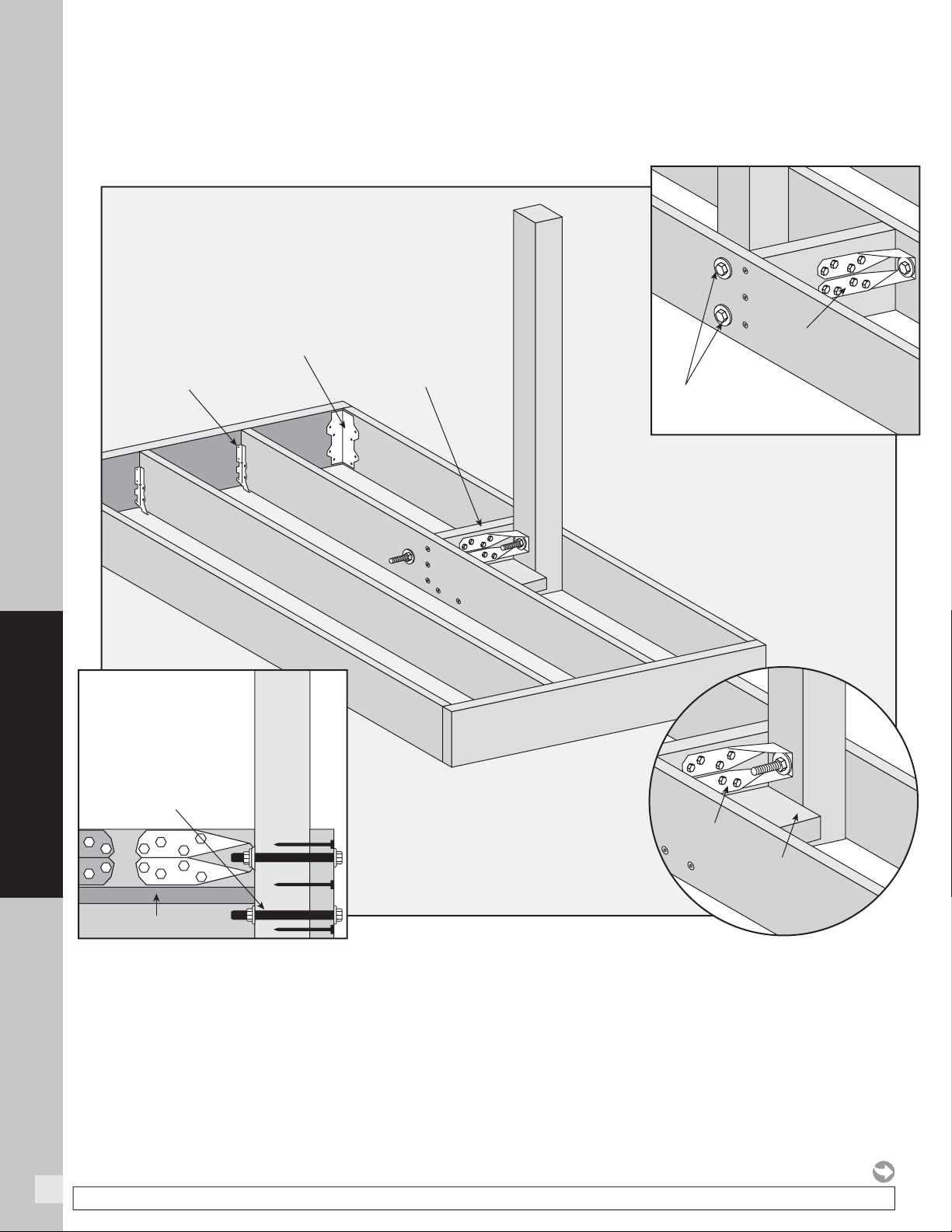
46
HOW TO INSTALL DECKING
NOTE: Construction methods are always improving. Please refer to www.trex.com for the most up-to-date installation requirements.
» TREX SUPPLIES (2) HG 1/2" X 8" (13 mm x 203 mm) BOLTS, NUTS, AND WASHERS.
» CUSTOMER MUST SUPPLY ADDITIONAL HG 1/2" X 8" (13 mm x 203 mm) BOLTS, NUTS, AND WASHERS.
SIDE VIEW
Simpson
L70Z
Crush Block
2"x 4"
(51 mm x 102 mm)
Simpson
DTT2Z
Simpson
DTT2Z
Trex Bolts 1/2" x 8"
(13 mm x 203 mm), Nuts,
and Washers
Simpson
LUS28Z
Bottom bolt runs
under the 2"x 4"
(51 mm x 102 mm)
crush block
Crush Block
Blocking
2"x 8"
(51 mm x 203 mm)
INSIDE MOUNT (SIDE JOIST)
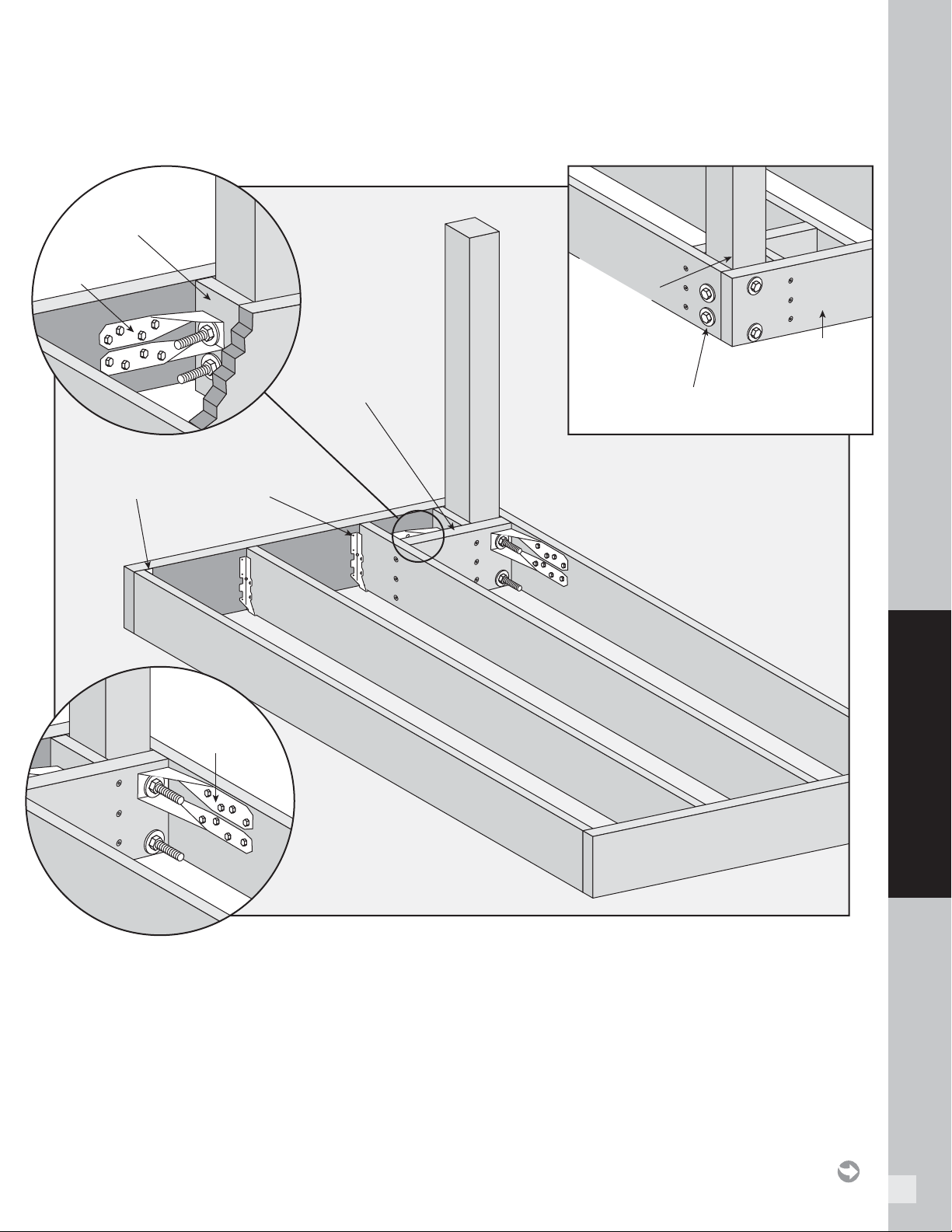
47
HOW TO INSTALL DECKING
INSIDE MOUNT (CORNER)
» TREX SUPPLIES (2) HG 1/2" X 8" (13 mm x 203 mm) BOLTS, NUTS, AND WASHERS.
» CUSTOMER MUST SUPPLY ADDITIONAL HG 1/2" X 8" (13 mm x 203 mm) BOLTS, NUTS, AND WASHERS.
Blocking 2"x 8"
(51 mm x 203 mm) min
Simpson
DTT2Z
Simpson
DTT2Z
Trex Bolts 1/2" x 8" (13 mm x 203 mm),
Nuts, and Washers
Front Rim
Joist
Simpson
L70Z
Simpson
LUS28Z
Blocking
2"x 8"
(51 mm x 203 mm)
NOTE:
If a L70Z is in
this location,
it must be
removed so
post mount
will fit properly.
NOTE: 1/2” x 8” (13 mm x 203 mm)
bolts must be wider (vertically) on front
rim and narrower on side joist to avoid
contact inside the post.
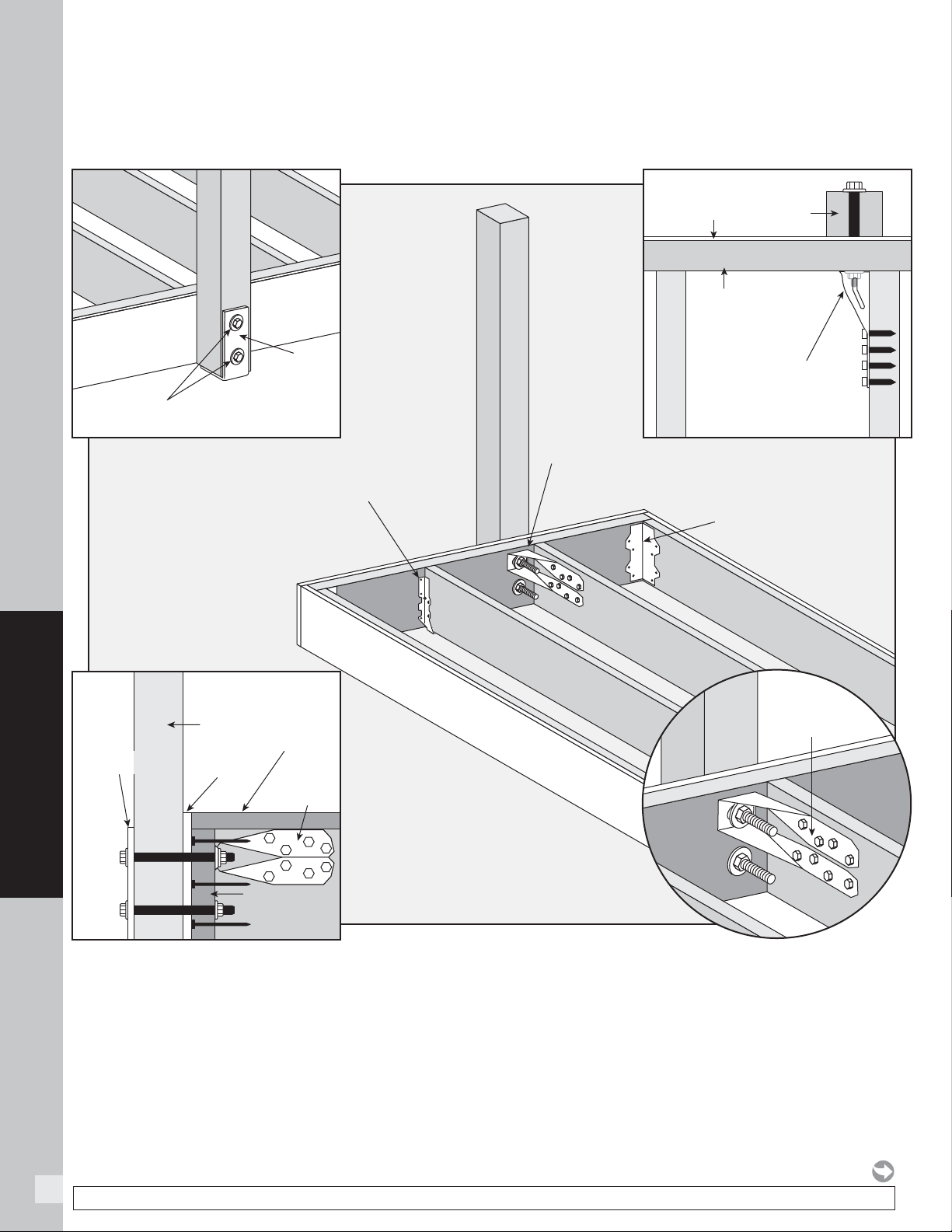
48
HOW TO INSTALL DECKING
NOTE: Construction methods are always improving. Please refer to www.trex.com for the most up-to-date installation requirements.
FASCIA MOUNT (FRONT RIM PLATE - NEXT TO JOIST)
» FOR USE WITH TREX REVEAL 6' RAILING SECTIONS ONLY.
» TREX SUPPLIES (2) HG 1/2" X 8" (13 mm x 203 mm) BOLTS, NUTS, AND WASHERS.
Simpson
DTT2Z
Simpson
LUS28Z
Trex Bolts 1/2" x 8" (13 mm x 203 mm),
Nuts, and Washers
Trex Fascia
Mount Kit
(L Bracket)
Front Rim
Joist
Post
Simpson
DTT2Z
Simpson
DTT2Z
Post
L-Bracket
Simpson
L70Z
SIDE VIEW
TOP VIEW
NOTE: If a joist hanger is in this location,
it must be removed so post mount
will fit properly.
Trex Fascia
Trex Fascia
Front Rim
Joist
Trex Decking
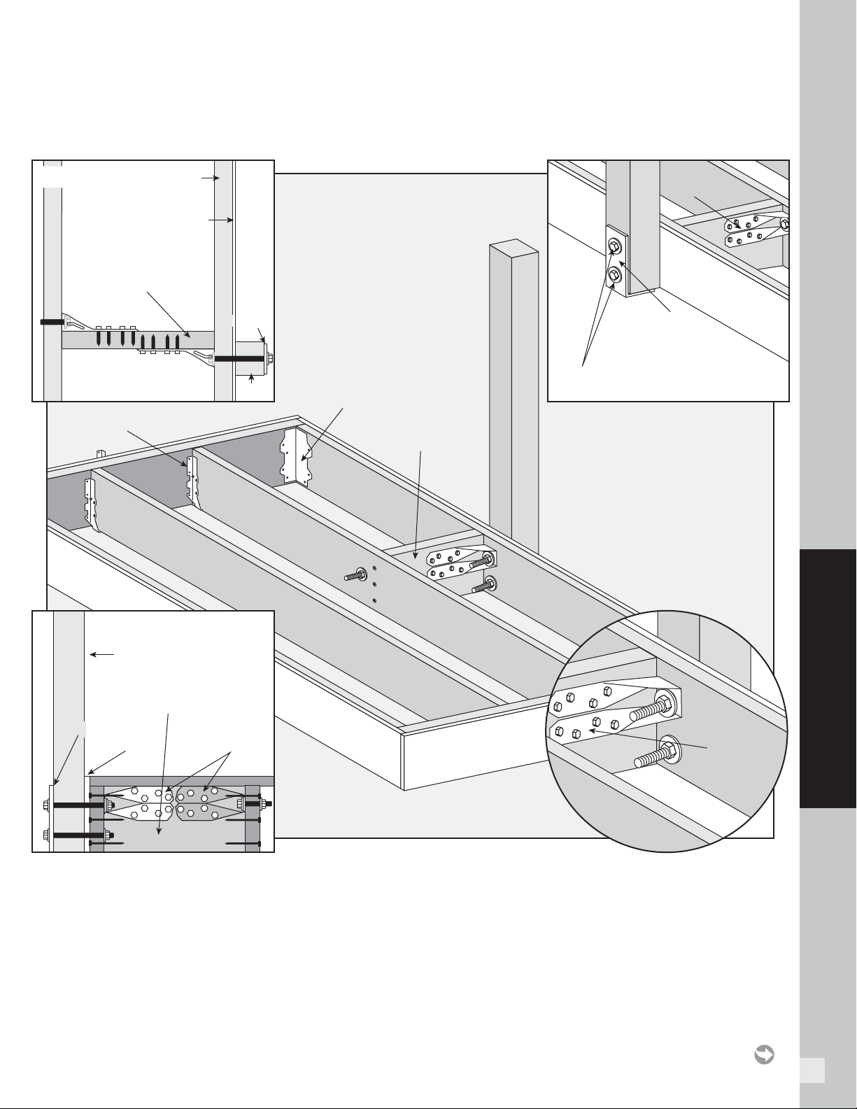
49
HOW TO INSTALL DECKING
FASCIA MOUNT (SIDE JOIST - WITH BLOCKING)
» TREX SUPPLIES (2) HG 1/2" X 8" (13 mm x 203 mm) BOLTS, NUTS, AND WASHERS.
» CUSTOMER MUST SUPPLY ADDITIONAL HG 1/2" X 8" (13 mm x 203 mm) BOLTS, NUTS, AND WASHERS.
Simpson
DTT2Z
Simpson
DTT2Z
Trex Fascia
Mount Kit
(L Bracket)
Simpson
LUS28Z
Post
Simpson
DTT2Z
Trex Bolts 1/2" x 8" (13 mm x 203 mm),
Nuts, and Washers
Simpson
L70Z
Blocking 2"x 8"
(51 mm x 203 mm) min
Side Rim
Joist
TOP VIEW
Post
L-Bracket
L-Bracket
SIDE VIEW
Blocking 2"x 8"
(51 mm x 203 mm) min
Blocking 2"x 8"
(51 mm x 203 mm) min
Trex Fascia
Trex Fascia
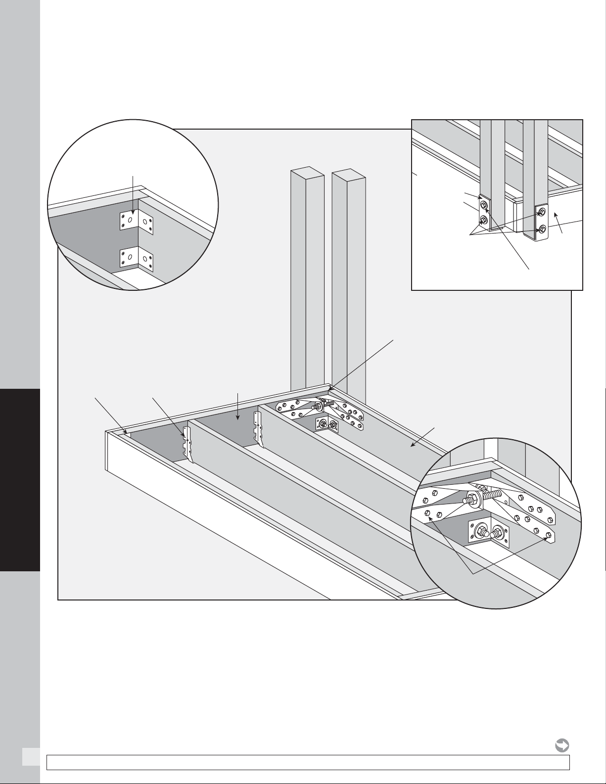
50
HOW TO INSTALL DECKING
NOTE: Construction methods are always improving. Please refer to www.trex.com for the most up-to-date installation requirements.
» 3/4" (19 mm) FASCIA MUST BE USED, OR BOLTS MUST BE CUT DOWN.
» INSTALL POST TIGHTLY ON RIM JOIST FIRST – NUTS WILL BE INACCESSIBLE LATER.
» MUST USE TREX FASCIA MOUNT CORNER BRACKET KIT.
1.
Install post on rim joist and fully tighten using Simpson DTT2Z on top bolt.
2. Run 10” (254 mm) bolt through gap in existing Simpson DTT2Z and tighten into second DTT2Z.
3. Install bottom bolt.
NOTE: If a L70Z is in this location,
it must be removed so post mount
will fit properly.
Simpson
DTT2Z
1 Bolt 1/2" x 10" (13 mm x 254 mm),
Nut, and Washer
3 Bolts 1/2" x 6"
(13 mm x 152 mm),
Nuts, and Washers
Simpson
LUS28Z
Simpson
L70Z
Front Rim Joist
Side Joist
Trex Fascia Mount Corner
Bracket (Kit)
Trex Fascia
Mount Kit
(L Bracket)
3/4"
(19 mm)
Fascia
FASCIA MOUNT (OUTSIDE FRAME CORNER)
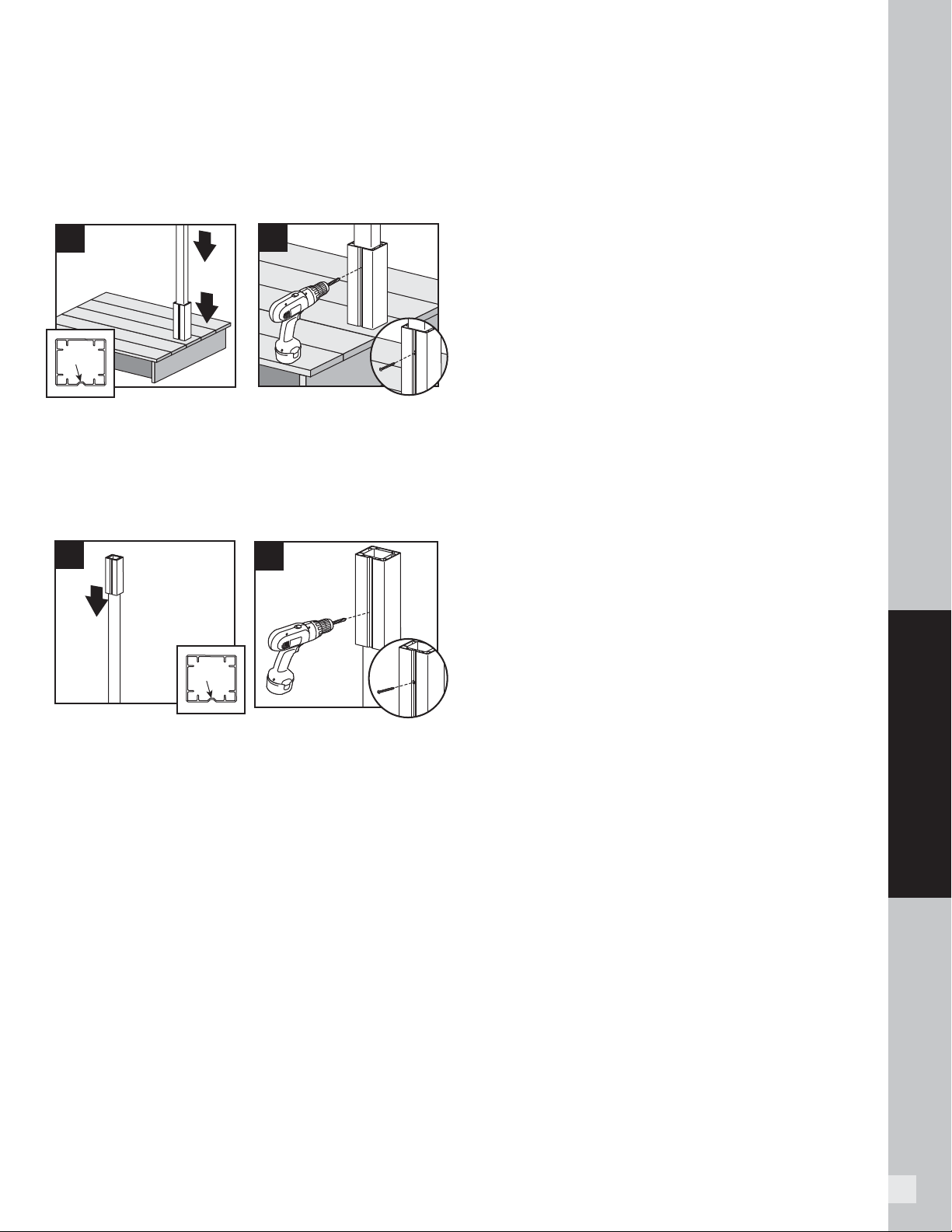
51
HOW TO INSTALL DECKING
COMPOSITE POST APPLICATIONS
Installation of Guide Blocks and Railing
NOTE: Pre-drilling is not required but is optional for
attachment of guide blocks to post. Use a drill bit slightly
smaller in size than that of screw being installed.
6. Place or rest bottom aluminum guide block on
bottom of post. Place guide on post so that notch is
on a side that does not require railing to be attached.
7. Attach bottom guide block using one 10 x 1” self-
tapping screw (provided) in notch to lock guide block
onto post.
8. Location of top guide block will vary slightly based on
type and height of railing being installed. Determine
this measurement and place top guide block in
location where top bracket for desired railing would
be approximately on center of the top railing bracket
location.
9. Attach top guide block using one 10 x 1” self-tapping
screw (provided) in notch to lock guide block onto
post.
» If using the joist mount post with composite post
sleeve, quantity of 18 self-tapping screws are provided
to cover all types of Trex railing bracket installations
(Transcend, Signature, and Select). Thus depending
on the type railing being installed, you may have
screws that are not used.
» If using 6x6 post sleeves, attach designated railing
brackets using #8-15 x 1-3/4" (4.4 cm) 316 stainless
steel self-tapping screws (
not provided
).
» Pre-drilling is not required but is optional for
attachment of brackets to guide blocks. Use a drill
bit slightly smaller in size than that of screw being
installed.
SIGNATURE (FORMERLY REVEAL)
POST APPLICATIONS
Installation of Railing
1. All required hardware is included with Signature
railing, follow Signature railing instructions for
complete installation requirements.
1
notch
3
notch
2
4
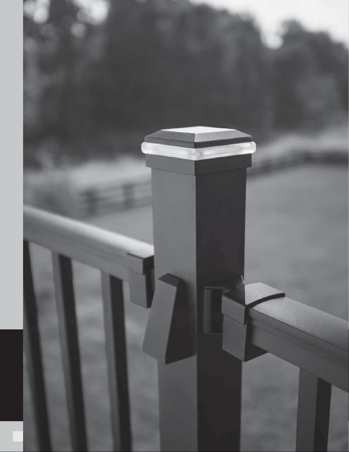
52
RAILING
RAILING
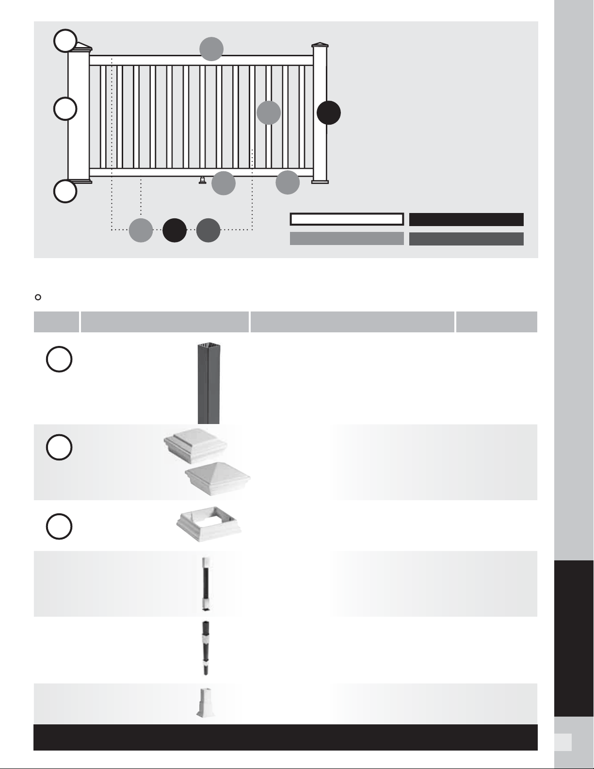
53
RAILING
5353
Post Sleeves, Caps & Skirts SKUs
These components can be used as steps 1 & 2 for all Trex railing lines.
1
2a
2b
WT Classic White
BK Charcoal Black
FP Fire Pit
GP Gravel Path
RS Rope Swing
TH Tree House
VL Vintage Lantern
3a
4
333
TRANSCEND RAILING
SIGNATURE RAILING
TREX
SELECT RAILING
TREX POST COMPONENTS
RAILING—
a lot easier than it looks
Selecting the right railing is pretty easy, but
each Trex railing line is a little different. Please
read the system descriptions at the top of each
product section so you can choose exactly which
railing components you need to complete your
design. For additional guidance, the chart to the
left depicts each railing system's components.
Each 4x4 and 6x6 post sleeve fits over a 4x4
pressure treated post or equivalent post mount.
Also available with LED lighting. See page 12.
3b
5
1+2
1
2a
2b
Post Sleeve
4" x 4" x 39" Post Sleeve
[4.45 in x 4.45 in x 40 in (113 mm x 113 mm x 101 cm) external dimensions]
4" x 4" x 108" Post Sleeve
[4.45 in x 4.45 in x 108 in (113 mm x 113 mm x 274 cm) external dimensions]
6" x 6" x 39" Post Sleeve
[5.5 in x 5.5 in x 39 in (139 mm x 139 mm x 990 mm) external dimensions]
6" x 6" x 108" Post Sleeve
[5.5 in x 5.5 in x 108 in (139 mm x 139 mm x 274 cm) external dimensions]
XX040439APS
XX0404108APS
WT060639APS
WT0606108APS
Post Sleeve Cap
Flat 4" x 4" Post Sleeve Cap (12/box)
Pyramid 4" x 4" Post Sleeve Cap (12/box)
[4.55 in x 4.55 in (115 mm x 115 mm) internal dimensions]
Flat 6" x 6" Post Sleeve Cap (12/box)
Pyramid 6" x 6" Post Sleeve Cap (12/box)
[5.55 in x 5.55 in (140 mm x 140 mm) internal dimensions]
XXSQCAP4X4
XXPYCAP4X4
WTSQCAP6X6
WTPYCAP6X6
Post Sleeve Skirt
4" x 4" Post Sleeve Skirt (12/box)
[4.55 in x 4.55 in (115 mm x 115 mm) internal dimensions]
6" x 6" Post Sleeve Skirt (12/box)
[5.55 in x 5.55 in (140 mm x 140 mm) internal dimensions]
XXSKIRT4X4
WTSKIRT6X6
Surface Mount Post
(for use with 4 x 4 composite
post sleeve)
Aluminum Surface Mount Post for 36" (914 mm) Rail Height (1/box)
Actual external dimensions of insert: 3.75 in x 3.75 in x 7 in (95 mm x 95 mm x 177 mm)
Aluminum Surface Mount Post for 42" (1066 mm) Rail Height (1/box)
Actual external dimensions of insert: 3.75 in x 3.75 in x 7 in (95 mm x 95 mm x 177 mm)
Surface Mount Post Hardware—Wood (10 kits/box)
ALPOSTMOUNT36
ALPOSTMOUNT42
ALPOSTHWDECK
ACCESSORY
ACCESSORY
ACCESSORY
Foot Block
Joist Mount Post
(for use with 4x4 composite
post sleeve)
Adjustable Foot Blocks (50/box)
Aluminum Joist Mount Post for use with all Trex railing heights (1/box)
Actual external dimensions of insert: 3.75 in x 3.75 in x 7 in (95 mm x 95 mm x 177 mm)
XXFTBLK
CPJMNTPOST63
COMPONENT
DESCRIPTIONSTEP ITEM NUMBER
XX = COLOR PREFIX:

54
RAILING
XX = COLOR PREFIX:
Signature Aluminum Railing (previously Reveal Railing)
Choose either Signature posts or Trex post sleeves, caps and skirts for steps 1 & 2. Pair with a rail & baluster kit (step 3).
1+2
Aluminum railing has a textured finish.
3
Aluminum Post with Cap & Skirt
Aluminum Crossover
Post
Signature aluminum posts fulfill
steps 1 & 2. If using Trex post sleeves,
refer to page 53.
Aluminum posts can only be
used with the Trex Signature line.
IRC Surface
Mount Hardware
Aluminum Joist
MountPost with
Cap and Skirt
Signature Fascia Mount Kit
(for use with wood framing)
Rail & Baluster Kit
» Top Rail
» Bottom Rail
» Balusters
» Mounting & Support Hardware
Signature Accessories
2.5" x 2.5" x 37" Post—Horizontal (IRC Compliant)
[2.5 in x 2.5 in x 37 in (63 mm x 63 mm x 939 mm) actual dimensions]
2.5" x 2.5" x 43" Post—Horizontal (IRC Compliant)
[2.5 in x 2.5 in x 43 in (63 mm x 63 mm x 109 cm) actual dimensions]
2.5" x 2.5" x 53" Post—Stair (IRC Compliant)
[2.5 in x 2.5 in x 53 in (63 mm x 63 mm x 134 cm) actual dimensions]
2.5" x 2.5" x 36" Crossover Post—Horizontal (IRC Compliant)
[2.5 in x 2.5 in x 36 in (63 mm x 63 mm x 914 mm) actual dimensions]
2.5" x 2.5" x 42" Crossover Post—Horizontal (IRC Compliant)
[2.5 in x 2.5 in x 42 in (63 mm x 63 mm x 106 cm) actual dimensions]
Aluminum Mounting Plate & Hardware
For use with all Trex 2.5" Surface Mount Aluminum Posts
Concrete Post Mount Kit
2.5" x 2.5" x 63"
[2.5 in x 2.5 in x 63 in (63 mm x 63 mm x 160 cm) actual dimensions]
For use with Joist Mount Signature Railing Post only.
6' x 36" Rail Kit w. Square Balusters—Horizontal
6' x 36" Rail Kit w. Square Balusters—Stair
8' x 36" Rail Kit w. Square Balusters—Horizontal
8' x 36" Rail Kit w. Square Balusters—Stair
6' x 42" Rail Kit w. Square Balusters—Horizontal
6' x 42" Rail Kit w. Square Balusters—Stair
8' x 42" Rail Kit w. Square Balusters—Horizontal
8' x 42" Rail Kit w. Square Balusters—Stair
6' x 36" Rail Kit w. Round Balusters—Horizontal
6' x 36" Rail Kit w. Round Balusters—Stair
8' x 36" Rail Kit w. Round Balusters—Horizontal
8' x 36" Rail Kit w. Round Balusters—Stair
6' x 42" Rail Kit w. Round Balu
sters—Horizontal
6' x 42" Rail Kit w. Round Balusters—Stair
8' x 42" Rail Kit w. Round Balusters—Horizontal
8' x 42" Rail Kit w. Round Balusters—Stair
6' x 36" Signature Assembled Panel (Square)—Horizontal*
8' x 36" Signature Assembled Panel (Square)—Horizontal*
6' x 42" Signature Assembled Panel (Square)—Horizontal*
8' x 42" Signature Assembled Panel (Square)—Horizontal*
*Does not include hardware
Dimensions above are actuals. See below for metrics.
[6' x 36": 72 in x 36 in (182 cm x 914 mm) actual dimensions]
[8' x 36": 96 in x 36 in (243 cm x 914 mm) actual dimensions]
[6' x 42": 72 in x 42 in (182 cm x 106 cm) actual dimensions]
[8' x 42": 96 in x 42 in (243 cm x 106
cm) actual dimensions]
Cocktail Rail Bracket (10/pack)
Fixed Bracket—Horizontal (4/pack)
Fixed Bracket—Stair (4/pack)
Swivel Bracket—Horizontal (2/pack–1 top, 1 bottom)
Swivel Bracket—Stair (2/pack–1 top, 1 bottom)
2.5" Horizontal Crossover Bracket (1/pack)
2.5" Swivel Crossover Bracket—Stair (1/pack)
Compound Swivel Bracket (2/pack–1 top, 1 bottom)
Aluminum Foot Block
Touch-up Pen
XXAL252537RCAP
XXAL252543RCAP
XXAL252553RCAP
XXAL252536RCCP
XXAL252542RCCP
ALPOSTHWDECK
ALPOSTHWCONC
XXJMNTPOST63
XXFMNTWOOD
XXAS0636HRK
XXAS0636SRK
XXAS0836HRK
XXAS0836SRK
XXAS0642HRK
XXAS0642SRK
XXAS0842HRK
XXAS0842SRK
XXAR0636HRK
XXAR0636SRK
XXAR0836HRK
XXAR0836SRK
XXAR0642HRK
XXAR0642SRK
XXAR0842HRK
XXAR0842SRK
BKAS0636HRPNL
BKAS0836HRPNL
BKAS0642HRPNL
BKAS0842HRPNL
XXCTBKTAL10PK
XXFHBKTAL
XXFSBKTAL
XXSWHBKTAL
XXSWSBKTAL
XX25FHCBKTAL
XX25RCSWSCBKTAL
XXCPDSWBKTAL
XXALFTBLK
XXTOUCHUPPEN
ACCESSORY
BK Charcoal Black BZ Bronze WT Classic White
COMPONENT
DESCRIPTIONSTEP ITEM NUMBER
SKUs
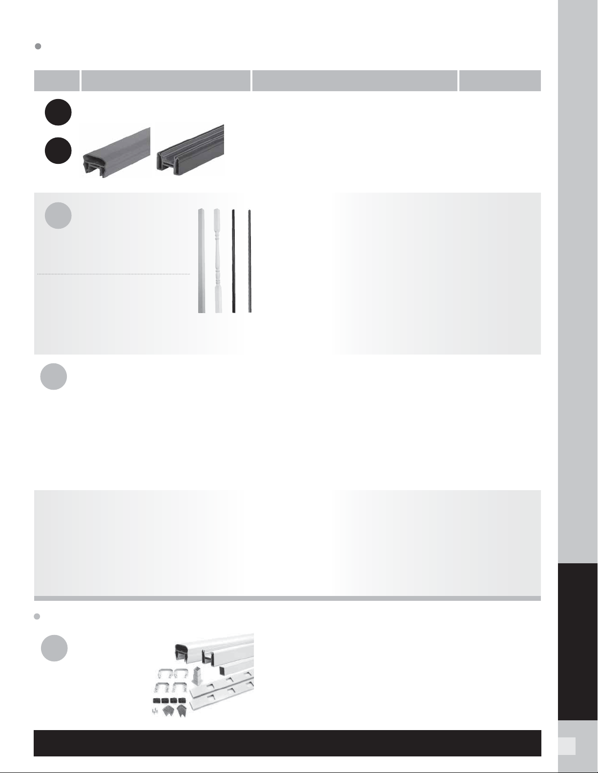
55
RAILING
COMPONENT
DESCRIPTIONSTEP ITEM NUMBER
Transcend Railing SKUs
Transcend is either a 5-step or 3-step process. Choose Trex post sleeves, caps and skirts (steps 1 & 2).
Then choose each component separately for a custom design (5-step).
3a
3b
4
Crown Universal
5
3
Or simply choose a rail & baluster kit in Classic White (3-step).
BALUSTER TYPE
PER 6'
SECTION
Square & Colonial (Horizontal application)
Square & Colonial (Stair application)
Aluminum (Horizontal application)
Aluminum (Stair application)
18
15
20
16
PER 8'
SECTION
13
11
15
12
Aluminum balusters are available in Charcoal Black,
Classic White and Bronze only (BK, WT, BZ).
Top & Bottom Rails
In this step, two rails (1 top, 1 bottom) must be selected.
Balusters/Spindles
See chart below for number of balusters
needed to complete each railing section.
Accessory Infill Kit
» 2 Baluster Spacers
» Adjustable
Foot Block
» Mounting Hardware
[6' Rail: 67.5 in (171 cm) actual length;
8' Rail: 91.5 in (232 cm) actual length]
Transcend Accessories
All accessories include a quantity of 12 per box
unless otherwise noted.
Rail & Baluster Kit
» Crown Top Rail
» Universal Bottom Rail
» Square Balusters
» Baluster Spacers
» Adjustable Foot Block
» Mounting Hardware
Available in Classic White only.
6' Crown Top Rail
8' Crown Top Rail
6' Universal Top/Bottom Rail
8' Universal Top/Bottom Rail
[6' Rail: 67.5 in (171 cm) actual length; 8' Rail: 91.5 in (232 cm) actual length]
Square Balusters for 36" Rail Height (16/pack)
[1.418 in x 1.418 in x 30.375 in (36 mm x 36 mm x 771 mm) actual dimensions]
Square Balusters for 42" Rail Height (16/pack)
[1.418 in x 1.418 in x 36.375 in (36 mm x 36 mm x 923 mm) actual dimensions]
Colonial Spindles for 36" Rail Height (16/pack)
[1.418 in x 1.418 in x 30.375 in (36 mm x 36 mm x 771 mm) actual dimensions]
Colonial Spindles for 42" Rail Height (16/pack)
[1.418 in x 1.418 in x 36.375 in (36 mm x 36 mm x 923 mm) actual dimensions]
Round Aluminum Balusters for 36" Rail Height (20/pack)
[.75 in x 30.25 in (19 mm x 768 mm) actual dimensions]
Round Aluminum Balusters for 42" Rail Height (20/pack)
[.75 in x 36.25 in (19 mm x 920 mm) actual dimensions]
Square Aluminum Balusters for 36" Rail Height (20/pack)
[.75 in x 30.25 in (19 mm x 768 mm) actual dimensions]
Square Aluminum Balusters for 42" Rail Height (20/pack)
[.75 in x 36.25 in (19 mm x 920 mm) actual dimensions]
6' Accessory Infill Kit for Square/Colonial Balusters—Horizontal
6' Accessory Infill Kit for Square/Colonial Balusters—Stair
8' Accessory Infill Kit for Square/Colonial Balusters—Horizontal
8' Accessory Infill Kit for Square/Colonial Balusters—Stair
6' Accessory Infill Kit for Round Aluminum Balusters—Horizon
tal
6' Accessory Infill Kit for Round Aluminum Balusters—Stair
8' Accessory Infill Kit for Round Aluminum Balusters—Horizontal
8' Accessory Infill Kit for Round Aluminum Balusters—Stair
6' Accessory Infill Kit for Square Aluminum Balusters—Horizontal
6' Accessory Infill Kit for Square Aluminum Balusters—Stair
8' Accessory Infill Kit for Square Aluminum Balusters—Horizontal
8' Accessory Infill Kit for Square Aluminum Balusters—Stair
6' Glass Panel Accessory Kit
[Glass panel mounting hardware;
glass panel not included
]
Mounting Hardware for Cut Rails
—
Horizontal
Mounting Hardw
are for Cut Rails
—
Stair
Transcend RSB Bracket Pack
—
Horizontal (24/box)
Transcend RSB Bracket Pack
—
Stair (24/box)
0 Degree Rail Gasket Pack
—
Horizontal
0 Degree Rail Gasket Pack
—
Stair
22.5 Degree Gasket Pack
45 Degree Birdsmouth Gasket Pack
(for 4 x 4)
45 Degree Gasket Pack (for 6 x 6)
6' x 36" Rail & Baluster Kit—Horizontal
6' x 36" Rail & Baluster Kit—Stair
8' x 36" Rail & Baluster Kit—Horizontal
8' x 36" Rail & Baluster Kit—Stair
[Actual dimensions: 6' Rail: 67.5 in x 36 in (171 cm x 914 mm);
8' Rail: 91.5 in x 36 in (232 cm x 914 mm)]
XXCROWNTR06
XXCROWNTR08
XXUNIVTBR06
XXUNIVTBR08
XX020230SBK
XX020236SBK
WT020230CSP
WT020236CSP
X
XTA30RBK
XXTA36RBK
XXTA30SBK
XXTA36SBK
XXSQHIK06
XXSQSIK06
XXSQHIK08
XXSQSIK08
XXRDHIK06
XXRDSIK06
XXRDHIK08
XXRDSIK08
XXASBHIK06
XXASBSIK06
XXASBHIK08
XXASBSIK08
XXGLIK06
XXHZACCYKIT
XXSTACCYKIT
TSHBRACKET
TSSBRACKET
XX00HGASK
XX00SGASK
XX22HGASK
XX45RSBADAPK
WT45HGASK
WT0636HRK
WT0636SRK
WT0836HRK
WT0836SRK
ACCESSORY
XX = COLOR PREFIX:
VL Vintage Lantern
BZ Bronze
(aluminum only)
RS Rope Swing
TH Tree House
FP Fire Pit
GP Gravel Path
WT Classic White
BK Charcoal Black
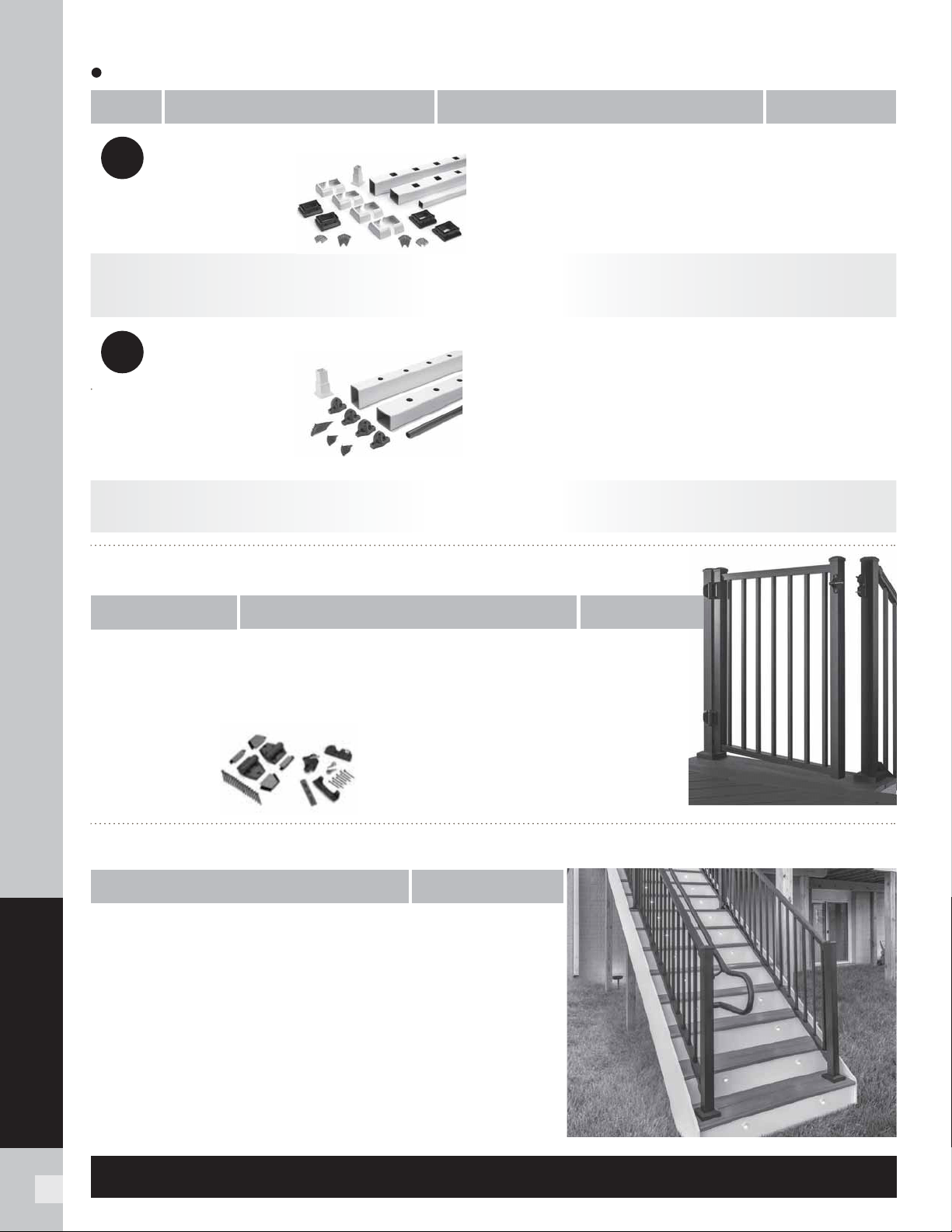
56
RAILING
6' x 36" Rail & Baluster Kit—Horizontal
6' x 36" Rail & Baluster Kit—Stair
8' x 36" Rail & Baluster Kit—Horizontal
8' x 36" Rail & Baluster Kit—Stair
[Actual dimensions: 6' Rail: 67.5 in x 36 in (171 cm x 914 mm);
8' Rail: 91.5 in x 36 in (232 cm x 914 mm)]
XX = COLOR PREFIX:
Aluminum railing has a textured finish.
BK Charcoal Black BZ Bronze WT Classic White
Select Railing SKUs
Select is a 3-step process. Choose Trex post sleeves, caps and skirts (steps 1 & 2) and a rail & baluster kit (step 3).
Aluminum ADA Compliant Handrail SKUs
A
luminum Gates SKUs
3
3
COMPONENT
COMPONENT
ITEM NUMBER
DESCRIPTION ITEM NUMBER
Gate Rail Kit
Available in all Aluminum colors.
Corner Mount
Post Return (“Candy Cane”)
5 Degree Elbow
31 Degree Elbow
34 Degree Elbow
36 Degree Elbow
90 Degree Elbow
Collar
Rail End Cap
90 Degree Wall Return
Wall Mount
4 in (101 mm) Internal Connector
1.375 in x 8 ft (34 mm x 243 cm) Hand Rail
XXALADAICORNER
XXALADA180CCANE
XXALADA05ELB
XXALADA31ELB
XXALADA34ELB
XXALADA36ELB
XXALADA90ELB
XXALADACLR
XXALADACAP
XXALADA90WR
XXALADAWMNT
XXALINTCONN
XXALADARAIL8
6' x 36" Rail & Aluminum Baluster Kit—Horizontal
6’ x 36” Rail & Aluminum Baluster Kit—Stair
8’ x 36” Rail & Aluminum Baluster Kit—Horizontal
8’ x 36” Rail & Aluminum Baluster Kit—Stair
6’ x 42” Rail & Aluminum Baluster Kit—Horizontal
8’ x 42” Rail & Aluminum Baluster Kit—Horizontal
8’ x 42” Rail & Aluminum Baluster Kit—Stair
[Actual dimensions: 6' Rail: 67.5 in x 36 in / 42 in (171 cm x 914 mm / 106 cm);
8' Rail: 91.5 in x 36 in / 42 in (232 cm x 914 mm / 106 cm);
36" Rail Height, Square Balusters, Adjustable up to 48" wide opening
36" Rail Height, Round Balusters, Adjustable up to 48" wide opening
42" Rail Height, Square Balusters, Adjustable up to 48" wide opening
42" Rail Height, Round Balusters, Adjustable up to 48" wide opening
[Actual height 36" Rail: 36 in (914 mm); 42" Rail: 42 in (106 cm)
Actual width is 47.5 in (120 cm) but can be cut to fit any width.]
WT0636HSELK
WT0636SSELK
WT0836HSELK
WT0836SSELK
WTRD0636HSELK
WTRD0636SSELK
WTRD0836HSELK
WTRD0836SSELK
WTRD0642HSELK
WTRD0842HSELK
WTRD0842SSELK
XX36SQADJGATE
XX36RDADJGATE
XX42SQADJGATE
XX42RDADJGATE
All Trex ADA handrail components are made of powder-coated aluminum.
For detailed installation instructions, visit trex.com.
Hardware Pack
2 Adjustable Self-Closing Hinges
1 Locking Hasp With Keys
Hardware for attachment to wood post with
composite sleeve or aluminum pos
ts
BKGATEHW
Classic White Rail &
Aluminum Baluster Kit
» Top Rail
» Bottom Rail
» Round Aluminum Balusters
» Adjustable Foot Block
» Hardware Pack
Available in Classic White with
Charcoal Black Aluminum Balusters only.
Select Accessories
Select Accessories
Mounting Hardware for Cut Rails—Horizontal (10 kits/box)
Mounting Hardware for Cut Rails—Stair (10 kits/box)
Mounting Hardware for Cut Rails—Horizontal (10 kits/box)
Mounting Hardware for Cut Rails—Stair (10 kits/box)
45 Degree Adapter Kit (10 kits/box)
BKENHZBKT
BKENSTBKT
WTHSELCUT
WTSSELCUT
WTSEL45ADP
ACCESSORY
ACCESSORY
Classic White Rail & Baluster Kit
» Top Rail
» Bottom Rail
» Square Balusters
» Adjustable Foot Block
» Hardware Pack
Available in Classic White only.
COMPONENT
DESCRIPTIONSTEP ITEM NUMBER
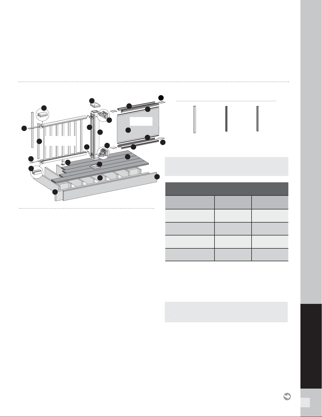
57
TRANSCEND RAILING
TREX TRANSCEND RAILING
PARTS
A. Crown or Universal
B. Universal
C. Trex railing support bracket (RSB)
D. TrexExpress
™
Railing Assembly Template*
E. Rail gaskets
F. Ba lus te rs
G. Post sleeve cap*
H. Post sleeve skirt*
I. Post sleeve – 4" x 4" (102 mm x 102 mm) or
6" x 6" (152 mm x 152 mm) post sleeve)**
J. Trex decking
K. Trex fascia
L. Code-approved wood joist – 2" x 8"
(51 mm x 203 mm)
M. Code-approved wood rim joist – 2" x 8"
(51 mm x 203 mm) or larger
N. Adjustable foot block
O. Baluster spacer
Trex Transcend Glass Panel Parts List
P. Panel support molding
Q. Tempered glass panel*
R. Trex panel support molding spacer
S. Weatherstripping
* Item not included in the Transcend railing kits.
** Both 4" x 4" (102 mm x 102 mm) and 6" x 6" (152 mm x 152 mm) post
sleeves are designed to fit over 4x4 pressure-treated post.
NOTES:
» TREX TRANSCEND RAILINGS ARE DESIGNED TO BE INSTALLED OVER THE DECKING FRAME OR ON INSIDE OF RIM JOIST. NOTCHING OF
PRESSURE-TREATED POSTS OR POSTS INSTALLED ON OUTSIDE OF RIM JOIST ARE NOT ALLOWED.
» All Trex Transcend railing lengths are manufactured at ON CENTER dimensions (spanning from center of each post): 67-5/8" (1718 mm) for
6' (1.83 m) on center, and 91-5/8" (2353 mm) for 8' (2.44 m) on center. Note that railings are designed to be slightly longer that required to allow
for very slight play in post placement – some minimal trimming may be required. IT IS VERY IMPORTANT TO MEASURE FIRST.
*
A
B
C
C
D
*
E
F
G
*
H
*
I
**
J
K
L
M
N
O
O
P
P
Q
R
R
S
S
Balusters
(standard shown)
Glass Panel
Option
Standard
BALUSTER OPTIONS
Round
Aluminum
Square
Aluminum
NOTE: Basic installation for balusters is the same for all options. When
using round or square aluminum balusters, use correct baluster spacers.
NOTE: If installing 42" (1067 mm) railing, use longer posts sleeves and
measure accordingly to ensure a proper cut. DO NOT CUT TO ACTUAL
42" LENGTH WITHOUT CONFIRMING WHAT STYLE OF RAILING YOU
ARE INSTALLING.
NOTE: If using post mounts, refer to detailed instructions provided
with post mounts for attaching these prior to installation of any railing
type.
NOTE: Pictorial representations shown may only show one style of
railing, while others may also be used. Review detailed instructions to
determine what railing styles and combinations can be used.
DETERMINING BALUSTERS NEEDED
Baluster Type
Per 6' OC
Section
Per 8' OC
Section
Square
(Horizontal Application)
13 18
Square
(Stair Application)
11 15
Round/Square Aluminum
(Horizontal Application)
15 20
Round/Square Aluminum
(Stair Application)
12 16
NOTE: If usin
g
post mounts, refer to detailed instructions provide
d
with post mounts for attachin
g
these prior to installation of an
y
railin
g
ty
pe.
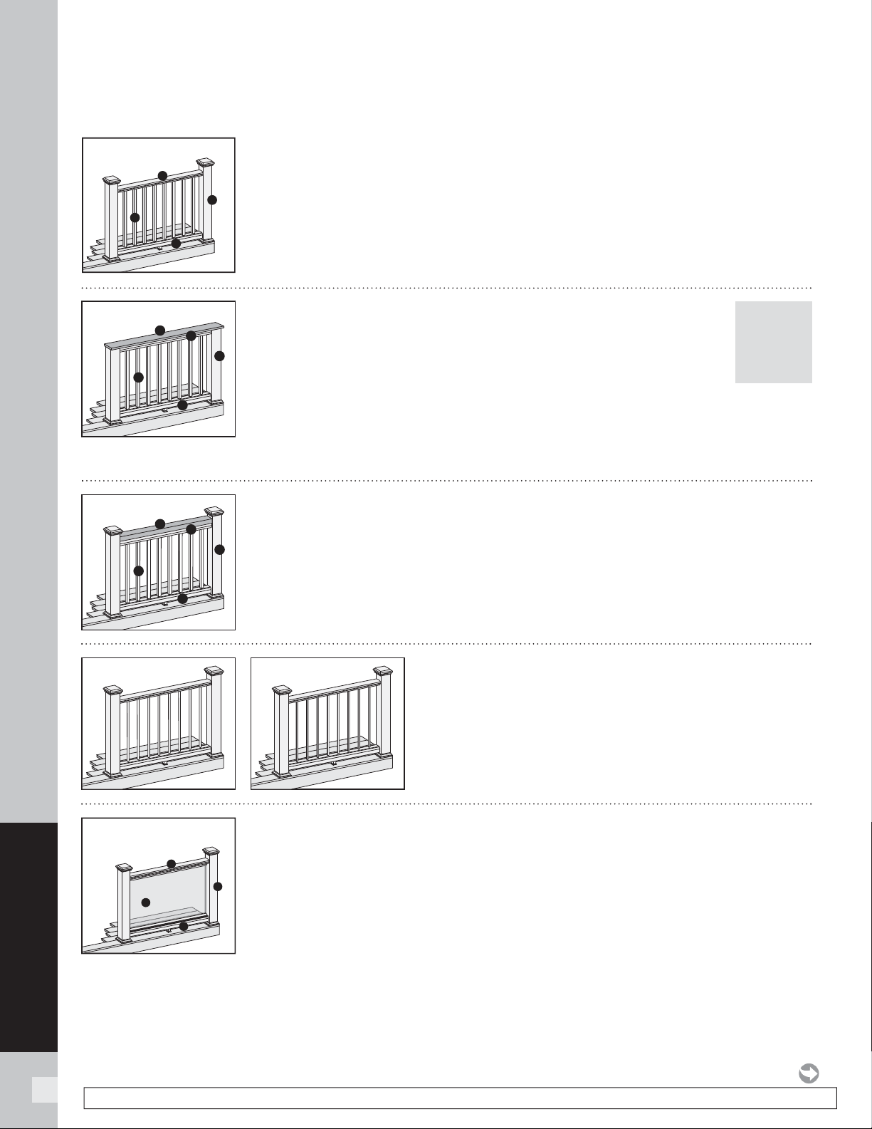
58
TRANSCEND RAILING
NOTE: Construction methods are always improving. Please refer to www.trex.com for the most up-to-date installation requirements.
TREX TRANSCEND
RAILING CONFIGURATIONS
Note: See specific installation instructions for attachment of Trex post mounts or Trex Joist Mount Posts prior to installing any railing.
Cutting post sleeves is NOT required.
A. Pressure-treated post/Trex post sleeve, Trex post mount/Trex post sleeve*, or Joist
Mount Post/Trex post sleeve* (INSIDE MOUNT ONLY)
B. Crown rail
C. Universal bottom
D. Trex balusters
See page 59 for “How to Install Standard Railing”.
B
C
D
A
Cutting post sleeves is NOT required.
A. Pressure-treated post/Trex post sleeve, Trex post mount/Trex post sleeve**, or Joist
mount post/Trex post sleeve** (INSIDE MOUNT ONLY)
B. Crown rail (use universal rail if building cocktail or traditional design with glass inserts)
C. Universal bottom
D. Tempered glass panel (NOT included in kit)
See page 64
for “How to Install Standard Glass Panel Railing”, page 66 for “How to Install
Cocktail Style Glass Panel Railing” (**NOTE: Trex Post Mounts or Trex Joist Mount Posts
cannot be used with this railing confi guration), and page
67 for “How to Install Traditional
Style Glass Panel Railing”.
NOTE: Glass panels are NOT recommended in stair applications.
B
C
D
A
Glass Panel
Standard Crown
Post sleeves WILL NEED TO BE CUT.
A. Pressure-treated post with Trex Transcend post sleeve
NOTE: » Only for use with 4" x 4" (102 mm x 102 mm) post sleeve.
» Trex post mounts cannot be used with Transcend
cocktail design.
B. Deck board top rail. NOTE: Contour and Escapes cannot be used.
C. Universal top rail
D. Universal bottom
E. Trex balusters
See page 61 for “How to Install Cocktail Railing”.
POST
SLEEVES
WILL
NEED TO
BE CUT
A
B
D
C
E
Cocktail
Cutting post sleeves is NOT required.
A. Pressure-treated post/Trex post sleeve, Trex post mount/Trex post sleeve*, or Joist mount
post/Trex post sleeve* (INSIDE MOUNT ONLY)
B. 2" x 4" (51 mm x 102 mm) lateral top rail
C. Universal top rail
D. Universal bottom
E. Trex balusters
See page 62 for “How to Install Traditional Railing”.
A
B
D
C
E
Traditional
» Follow desired railing style instructions found above, substituting
correct baluster spacer for type of baluster being used.
» Refer to detailed instructions for added steps when using
round and square aluminum balusters. See page 63.
Round Aluminum Square Aluminum
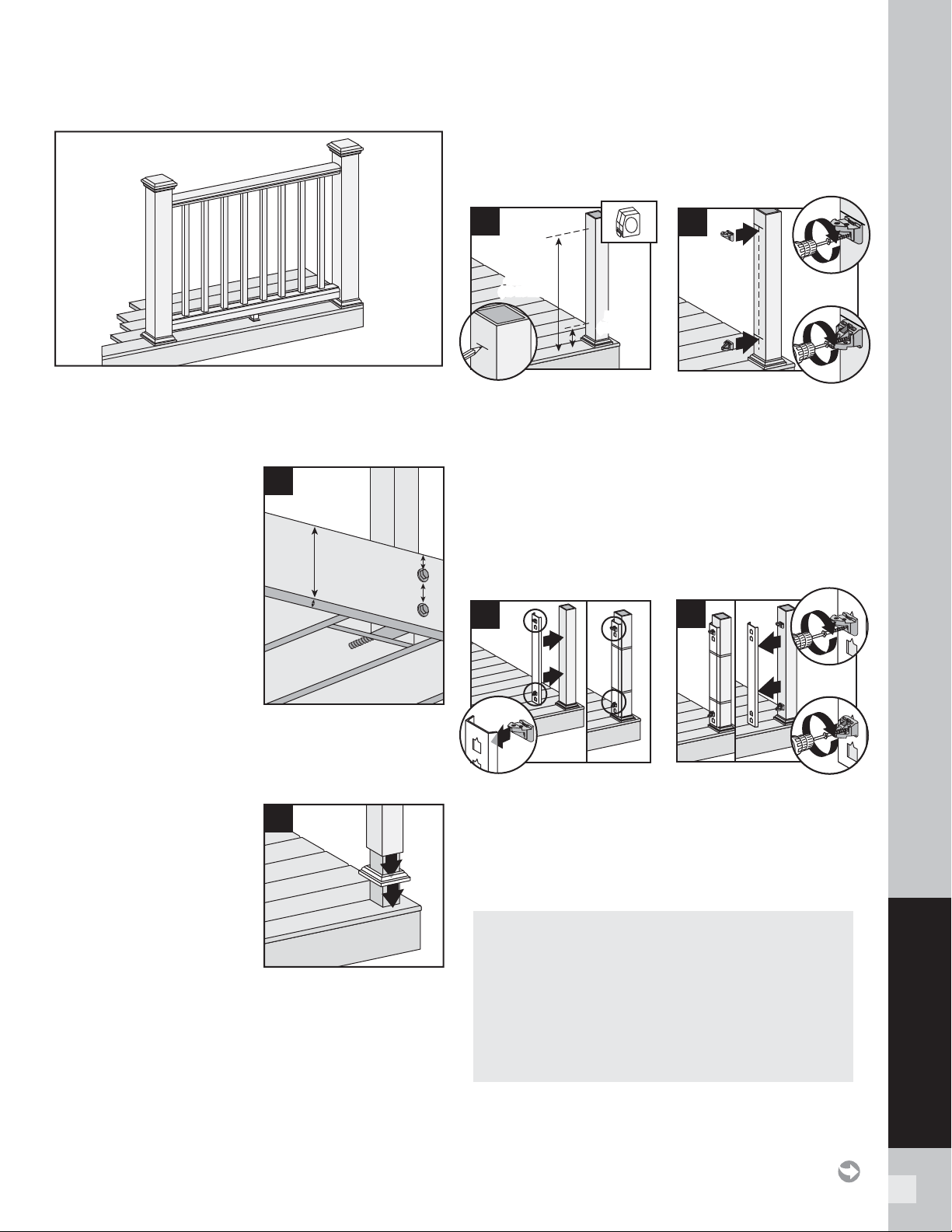
59
TRANSCEND RAILING
HOW TO INSTALL STANDARD RAILING
TREX TRANSCEND
Read all instructions BEFORE installation.
Important: Post sleeves are NOT to be cut for this design
style.
Installing Pressure-
Treated Posts
» Posts are to be installed
6' (1.83 m) or 8'
(2.44 m) on center
to accommodate
appropriate railing
length.
» Attach posts using 1/2"
(130 mm) carriage bolts.
» Minimum joist size is
2" x 8" (51 mm x 203 mm).
» Top bolts must be 1" (25 mm) from tops of joists.
» Bottom bolts must be 5-1/8" (130 mm) from top bolts.
NOTE: Blocking can be added for extra strength.
Installing Post Sleeve
Skirts and Post Sleeves
2. Slide post sleeve skirt
over post and down to rest
on decking surface. Slide
post sleeve over post and
position inside post sleeve
skirt.
NOTE: Shims can be used to plumb post sleeves.
Installing Railing Support Brackets (RSBs)
Option 1: Without TrexExpress railing template
3a. Mark 5-1/2" (140 mm) and 35-1/16" (891 mm) from
deck surface OR for 42" (1067 mm) height, mark
5-1/2" (140 mm) and 41-1/16" (1043 mm) from the
deck surface.
3b. Place RSBs directly under marks, center on posts,
and secure with 2" (51 mm) wood screws (provided
with post sleeve). Place top RSBs fl at side UP,
bottom RSBs fl at side DOWN.
Option 2: With TrexExpress railing template
3c. Place RSBs in template. Place top RSBs fl at side
UP, bottom RSBs fl at side DOWN. Secure
template on post with tape or rubber band, with
bottom of template resting on post skirt.
3d. Secure RSBs with 2" (51 mm) wood screws
(provided in railing kit) and remove template.
NOTES:
Special steps are necessary when using
6" x 6" (152 mm x 152 mm) plastic TrexExpress template.
» Cut off 1/2" (13 mm) from the bottom (blue arrows up)
of the tool BEFORE fi rst use.
» Position top RSBs ONLY, 6" (152 mm) higher for
42" (1067 mm) rail height.
» Secure RSBs with 2-1/2" (64 mm) wood screws
(provided with post sleeve) and remove template
.
1
2
2
35-1/16\
(89.1 cm)
or
41-1/16\
(1043 mm)
35-1/16"
(891 mm)
or
41-1/16"
(1043 mm)
5-1/2
"
(140 mm)
5-1/2"
(140 mm)
3a
1
3
3b
4
2
1
5-1/8" (130 mm) min.
2" x 8"
(51 mm x
203 mm)
min.
1" (25 mm) min.
3c
3
3
3d
2
1
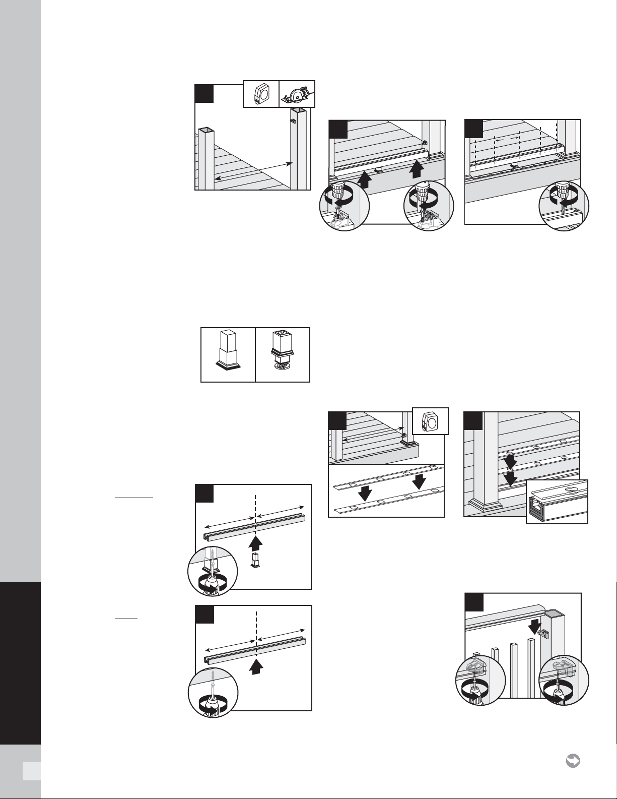
60
TRANSCEND RAILING
Cutting Railings
4. Measure between posts and
cut rails to same length.
NOTES:
» If using optional rail
gaskets, subtract 1/16"
(1.6 mm) from each end.
» Attach baluster spacers to
railing before cutting to allow for cleaner cut and less
work.
» When measuring, cut equal lengths from each side of
railing and baluster spacer to ensure equal spacing of
balusters per each railing section.
» In some cases, the gasket can be attached before
tightening railing to RSB.
» If gaskets are tight, use a small fl at head screwdriver
to compress the tabs of the gasket if they are stuck
outside the rail.
IMPORTANT NOTE
REGARDING FOOT BLOCK
INSTALLATION:
» Determine which style
of foot block is included.
Original foot block is a one-piece part that is adjustable.
New foot block is a two-piece part with turning base
mount.
» Also refer to detailed instructions (Trex Transcend®
rail instructions) included with foot block prior to
installation of railing section as these include other
required steps for proper installation.
If Attaching Original Foot
Block to Bottom Rail
5a. Center foot block in
universal rail channel
and attach per Original
foot block instructions.
DO NOT extend foot
block.
If Attaching New Foot Block
to Bottom Rail
5b. Invert the bottom rail.
Center and drill a hole
using a 3/16" drill bit.
This will be location for
foot block attachment
(to be installed last).
Attaching Bottom Rail (Universal Rail), Adding Weep
Holes
6a. Lift bottom rail so RSBs are in the channel and attach
with three self-tapping screws provided (use three
outer holes; do not use hole in RSB that is closest to
post). If two hole bracket is included, attach with two
self-tapping holes (provided).
6b. Center and drill 5/16" (8 mm) weep holes through
bottom rail channel to allow for water drainage. Holes
should be placed between fi rst two balusters on each
side and approx. 2' (610 mm) spans along length of rail.
Note: To determine weep hole locations, temporarily
place lower baluster spacer beside lower rail and mark
inside of channel in locations accordingly.
Placing Baluster Spacers and Balusters
7. Cut baluster spacers the same length as rails, equally
spaced so holes line up.
8. Snap baluster spacer into bottom rail. Place inverted
baluster spacer on top of fi rst baluster spacer. Place
balusters in baluster spacer holes.
Attaching Top Rail –
Crown Rail
9. Place crown rail on RSBs
with balusters in rail
channels. Attach top rail
to RSB with three self-
tapping screws provided
(use three outer holes;
do not use hole in RSB
that is closest to post). If
two hole bracket is included, attach with two self-tapping
holes (provided).
HOW TO INSTALL STANDARD RAILING/CONTINUED
TREX TRANSCEND
Original
New
4
1
5a
2
5b
1
1
6a
2
3
Hole
RSB
2
Hole
RSB
2
6b
2’
(.61 m)
8
7
1
9
x2
2
3
Hole
RSB
x2
2
2
Hole
RSB
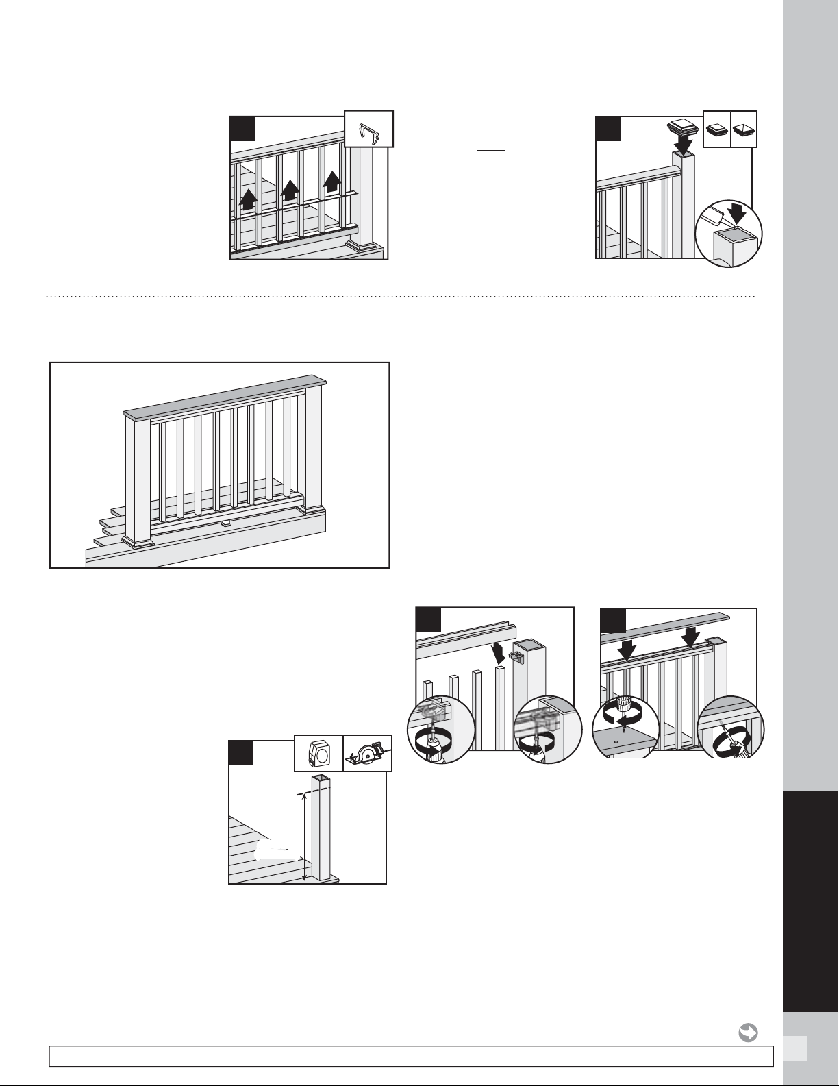
61
TRANSCEND RAILING
NOTE: Construction methods are always improving. Please refer to www.trex.com for the most up-to-date installation requirements.
HOW TO INSTALL STANDARD RAILING/CONTINUED
TREX TRANSCEND
10. Slide baluster spacer up
and snap into top rail.
Place optional top rail
gaskets on each end of
rail.
Attaching Post Caps and
Installing New Foot Blocks
11. Secure post caps with
silicone or PVC adhesive.
Attach New foot block per
foot block instructions.
Note: Clean-up any excess
adhesive before drying.
2
10
Option
2
2
11
3
1
HOW TO INSTALL COCKTAIL RAILING
TREX TRANSCEND
Important: ONLY use with 4" x 4" (102 mm x 102 mm)
post and post sleeve. Cutting post and post sleeve ONLY
apply to the Transcend Cocktail railing.
1.
Installing Pressure-Treated Posts
See instructions on page 59.
Cutting Post and Post Sleeve
1a. Mark and cut post and post sleeve measuring from deck
surface:
» 36-3/16" (919 mm) for
36" (914 mm) height.
» 42-3/16" (1072 mm)
for 42" (1067 mm)
height.
2. Installing Post
Sleeve Skirts and
Post Sleeves See
instructions on page 59.
3.
Installing Railing Support Brackets (RSBs)
See instructions on page 59.
4.
Cutting Railings
See instructions on page 60.
5.
Attaching Foot Block
See instructions on page 60.
6.
Attaching Bottom Rail (Universal Rail), Adding
Weep Holes.
See instructions on page 60.
7-8.
Placing Baluster Spacers and Balusters
See instructions on page 60.
Attaching Inverted Universal Rail as Top Rail
9. Place inverted universal rail onto RSBs with balusters
in channel. Attach universal rail to RSBs with three
self-tapping screws provided (use three outer holes;
do not use hole in RSB that is closest to post). If two
hole bracket is included, attach with two self-tapping
holes (provided).
10. Place deck boards (DO NOT use Escapes deck boards
for top rail) over universal rails. Attach boards on
each post with Trex-recommended composite screws
(quantity of 2 per each board end). Secure boards to
36-3/16"
(919 mm)
or
42-3/16"
(1072 mm)
36-3/16"
(919 mm)
or
42-3/16"
(1072 mm)
1a
1
9
2
3
Hole
RSB
2
2
Hole
RSB
1
1
10
2
3
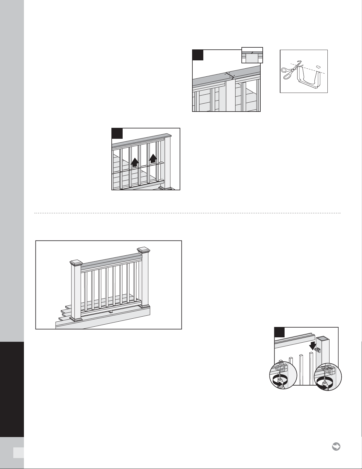
62
TRANSCEND RAILING
universal rails from underside of railing into bottom of
decking board, with 2 " (51 mm) pan-head screws (not
provided) at an angle every 16 " (406 mm) on center.
IMPORTANT NOTES:
»
If using Select decking, USE maximum length 1-3/4"
(44 mm) screw and NOT 2" (51 mm) screw.
»
Screws that are used for attachment of decking board
to railing MUST be attached at angle to prevent screw
from penetrating through the top of decking board.
11. Slide baluster spacers up
and snap into universal
rails.
NOTE: If necessary, cut
tips off rail gaskets prior to
installation.
12. Use scarf cut for posts where two deck boards meet.
NOTES:
»
If installing in weather below 40°F (4.5°C), leave 1/8 " (3
mm) gap between deck boards.
»
Deck boards can overhang end of last post
maximum 1/2" (13 mm).
11
12
Optional
HOW TO INSTALL COCKTAIL RAILING/CONTINUED
TREX TRANSCEND
1. Installing Pressure-Treated Posts
See instructions on page 59.
2.
Installing Post Sleeve Skirts and Post Sleeves
See instructions on page 59.
3.
Installing Railing Support Brackets (RSBs)
See instructions on page 59.
4.
Cutting Railings
See instructions on page 60.
5.
Attaching Foot Block
See instructions on page 60.
6.
Attaching Bottom Rail (Universal Rail), Adding
Weep Holes
See instructions on page 60.
7-8.
Placing Baluster Spacers and Balusters
See instructions on page 60.
Attaching Inverted Universal Rail as Top Rail
9. Place inverted universal
rail onto RSBs with
balusters in channel.
Attach universal rail
with three self-tapping
screws provided (use
three outer holes; do
not use hole in RSB
that is closest to post).
If two hole bracket is
included, attach with
two self-tapping holes
(provided).
HOW TO INSTALL TRADITIONAL RAILING
TREX TRANSCEND
1
9
x2
2
2
Hole
RSB
2
3
Hole
RSB
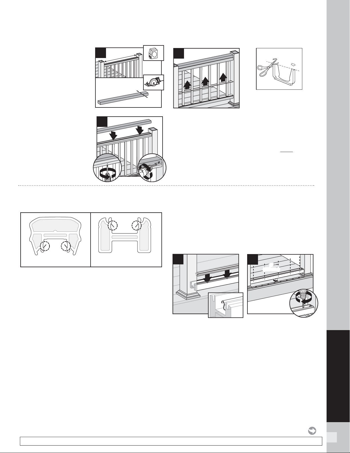
63
TRANSCEND RAILING
NOTE: Construction methods are always improving. Please refer to www.trex.com for the most up-to-date installation requirements.
10. Measure between posts
and cut 2" x 4" (51 mm x
102 mm) to length. Place
2" x 4" (51 mm x 102 mm)
on universal rail. Attach
board to rail with 2" (51
mm) pan-head screws
(not provided) every 16"
(406 mm) on center.
11. Pre-drill a pilot hole and
toenail 2-1/2" (64 mm)
composite decking
screw (not provided) at
each end of 2" x 4"
(51 mm x 102 mm)
into post on back side
of rail (side not facing
decking).
12. Slide baluster spacer up and snap into universal rail.
NOTE: If necessary, cut tips off rail gaskets prior to
installation.
13.
Attaching Post Caps and Installing New Foot
Block
See instructions on page 61.
10
1
HOW TO INSTALL TRADITIONAL RAILING/CONTINUED
TREX TRANSCEND
1
1
11
3
2
12
Optional
HOW TO INSTALL ROUND OR SQUARE ALUMINUM BALUSTERS
TREX TRANSCEND
NOTE: Older style Crown and Universal Rails have
"fl ippers" on the inside of the channels. Using EXTREME
CAUTION, remove/cut these fl ippers on each side to
allow for the fi t of the aluminum baluster adaptor strip.
1. Installing Pressure-Treated Posts
See instructions on page 59.
2.
Installing Post Sleeve Skirts and Post Sleeves
See instructions on page 59.
3.
Installing Railing Support Brackets (RSBs)
See instructions on page 59.
4.
Cutting Railings
See instructions on page 60.
5.
Attaching Foot Block
See instructions on page 60.
6.
Attaching Bottom Rail (Universal Rail)
See instructions on page 60.
Installing Aluminum Baluster Adaptor Strip,
Adding Weep Holes, and Baluster Spacers
7. After bottom rail is fully installed, place aluminum
baluster adaptor strip into channel of bottom rail,
ensuring that it’s fully seated into the channel. When
rail lengths are non-standard, the baluster adaptor
strip will need to be cut 2-1/2" (64 mm) shorter than
the rail to allow clearance for the RSB’s on each end.
7a. Center and drill 5/16" (8 mm) weep holes through
bottom rail channel and adaptor strip to allow for
water drainage. Holes should be placed between fi rst
two balusters on each side and approx. 2' (610 mm)
spans along length of rail.
Crown Rail
with “flippers”
Universal Rail
with “flippers”
7
7a
2
'
(610 mm)
2'
(610 mm)
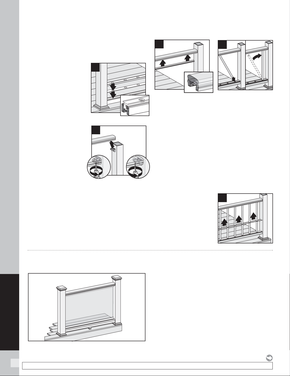
64
TRANSCEND RAILING
NOTE: Construction methods are always improving. Please refer to www.trex.com for the most up-to-date installation requirements.
HOW TO INSTALL ROUND OR SQUARE ALUMINUM BALUSTERS/CONTINUED
TREX TRANSCEND
NOTE: To determine weep hole locations, temporarily
place lower baluster spacer beside lower rail and mark
inside of channel in locations accordingly.
8. Snap baluster spacer
into bottom rail. Place
inverted baluster
spacer on top of fi rst
baluster spacer.
Attaching Top Rail,
Aluminum Baluster
Adaptor Strip, and
Balusters and Bottom
Baluster Spacer
9. Place crown or rail on
RSBs with balusters in
rail channels. Attach
top rail to RSB with
three self-tapping
screws provided (use
three outer holes; do
not use hole in RSB
that is closest to post).
If two hole bracket
is included, attach with two self-tapping holes
(provided).
10. After top rail is fully installed, place aluminum
baluster adaptor strip into channel of top rail,
ensuring that it’s fully seated into the channel.
11. Working at slight angle, press baluster through both
baluster spacers and into bottom aluminum baluster
adaptor strip, ensuring balusters are tight. Once
balusters are seated into aluminum baluster adaptor
strip of bottom rail, maneuver baluster into upper rail
aluminum baluster adaptor strip. Some force will be
needed to press balusters into place and level these.
Tip: Ensure balusters are level prior to attempting to
slide baluster spacer up. This will allow for the baluster
spacer to move up freely and snap into upper rail. Use
of a rubber mallet to gently tap balusters in level is
recommended.
12. Slide baluster spacer
up and snap into top
rail. Place optional top
rail gaskets on each
end of rail.
8
1
9
2
2
Hole
RSB
x2
2
3
Hole
RSB
10
2
12
2
1
11
HOW TO INSTALL STANDARD GLASS PANEL RAILING
TREX TRANSCEND
NOTES: Read all instructions BEFORE installation.
» You must purchase the 1/4" (6 mm) tempered glass
panels. See dimensions below.
» Glass panels ONLY for use with maximum 6' (1.83 m)
on center post spacing.
» NOT recommended for stair applications.
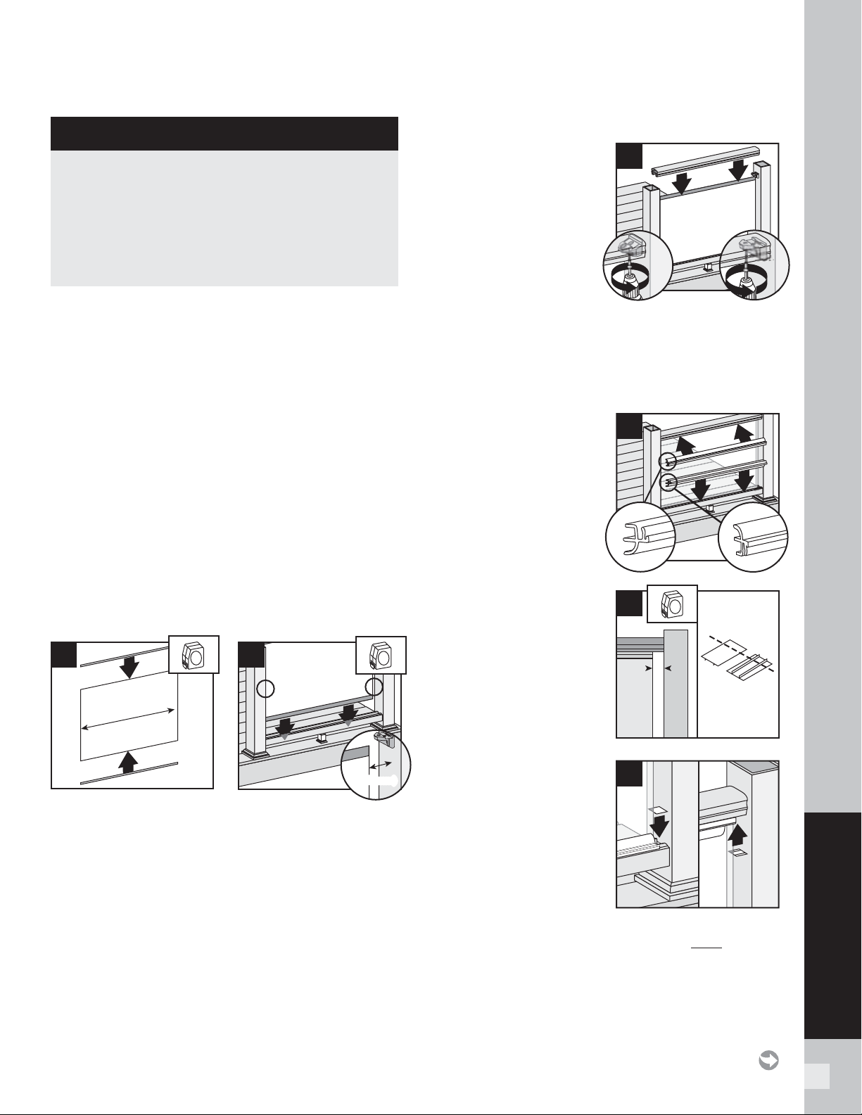
65
TRANSCEND RAILING
HOW TO INSTALL STANDARD GLASS PANEL RAILING/CONTINUED
TREX TRANSCEND
1. Installing Pressure-Treated Posts
See instructions on page 59.
2.
Installing Post Sleeve Skirts and Post Sleeves
See instructions on page 59.
3.
Installing Railing Support Brackets (RSBs)
See instructions on page 59.
4.
Cutting Railings
See instructions on page 60.
5.
Attaching Foot Block
See instructions on page 60.
6.
Attaching Bottom Rail (Universal Rail), Adding
Weep Holes
See instructions on page 60.
Attaching Weatherstripping and Positioning Panel
7. Push black-edged trim onto upper and lower edges of
panel. Be sure trim runs entire length of glass. Extra
trim can be cut with razor blade or scissors.
8. Position panel with weatherstripping into lower rail
channel. Center panel between posts with about 2"
(51 mm) of air space on each side of panel.
Attaching Top (Crown) Rail
9. Place top rail over
RSB brackets and
glass panel. Attach
top rail to RSB with
three self-tapping
screws provided (use
threeouter holes; do
not use hole in RSB
that is closest to post).
If two hole bracket is
included, attach with
two self-tapping holes (provided).
NOTE: Avoid hitting glass panel while using the drill.
Attaching Panel Support Molding
10. Push PSM into rail
to complete snap
connection. Lower rail
PSM edge rests on top
of rail. Top rail PSM
snaps fl ush into rail.
Hiding Brackets
11. Cut Transcend baluster
spacer into four lengths
equal to distance
between the glass panel
and posts. Cut slowly
and one at a time, to
avoid chipping.
12. Snap spacer into bottom
and top rail to hide
brackets and create a
seamless look.
13.
Attaching Post Caps and Installing New Foot
Blocks
See instructions on page 61.
TEMPERED GLASS PANEL DIMENSIONS
» 36" (914 mm) high rail:
1/4" x 30" x 63-1/2" max.
(6 mm x 762 mm x 1613 mm)
» 42" (1067 mm) high rail:
1/4" x 36" x 63-1/2" max.
(6 mm x 914 mm x 1613 mm)
8
2" (51 mm)2" (51 mm)
63-1/2"
(1613 mm)
7
1
1
9
x2
2
3
Hole
RSB
x2
2
2
Hole
RSB
10
11
12

66
TRANSCEND RAILING
NOTE: Construction methods are always improving. Please refer to www.trex.com for the most up-to-date installation requirements.
HOW TO INSTALL COCKTAIL STYLE GLASS PANEL RAILING
TREX TRANSCEND
TEMPERED GLASS PANEL DIMENSIONS
» 36" (914 mm) high rail:
1/4" x 30" x 63-1/2" max.
(6 mm x 762 mm x 1613 mm)
» 42" (1067 mm) high rail:
1/4" x 36" x 63-1/2" max.
(6 mm x 914 mm x 1613 mm)
NOTES: Read all instructions BEFORE installation.
» You must purchase the 1/4" (6 mm) tempered glass
panels. See dimensions below.
» Glass panels ONLY for use with maximum 6' (1.83 m)
on center post spacing.
» NOT recommended for stair applications.
» Trex post mounts cannot be used for this application.
1.
Installing Pressure-Treated Posts
See instructions on page 59.
NOTE: If installing glass with cocktail rail design, rail posts
and post sleeves must be cut.
1a.
Cutting Post and Post Sleeve
See instructions on page 59.
2.
Installing Post Sleeve Skirts and Post Sleeves
See instructions on page 59.
3.
Installing Railing Support Brackets (RSBs)
See instructions on page 59.
4.
Cutting Railings
See instructions on page 60.
5.
Attaching Foot Block
See instructions on page 60.
6.
Attaching Bottom Rail (Universal Rail), Adding
Weep Holes
See instructions on page 60.
7-8.
Attaching Weatherstripping and Positioning
Panel
See instructions on page 65.
Attaching Top Rail
9. Cut deck boards to appropriate length of railing span,
remembering to include extra space on each side of
the deck board to allow for attachment to the post.
Decking boards must cover 1/2 of the pressure-
treated post to allow this to be fastened later. If you
include extra decking material on each side this can
be cut off later if need be.
10. Place inverted deck board (place top side of deck
board down) on clean, fl at surface.
(DO NOT use Escapes deck boards for top rail.)
11. Place Universal rail (orient this properly so when
fl ipped over, the universal rail will accept the baluster
spacer and balusters), on the deck board, centered in
both directions to allow fi nal attachment to post.
11
10
9
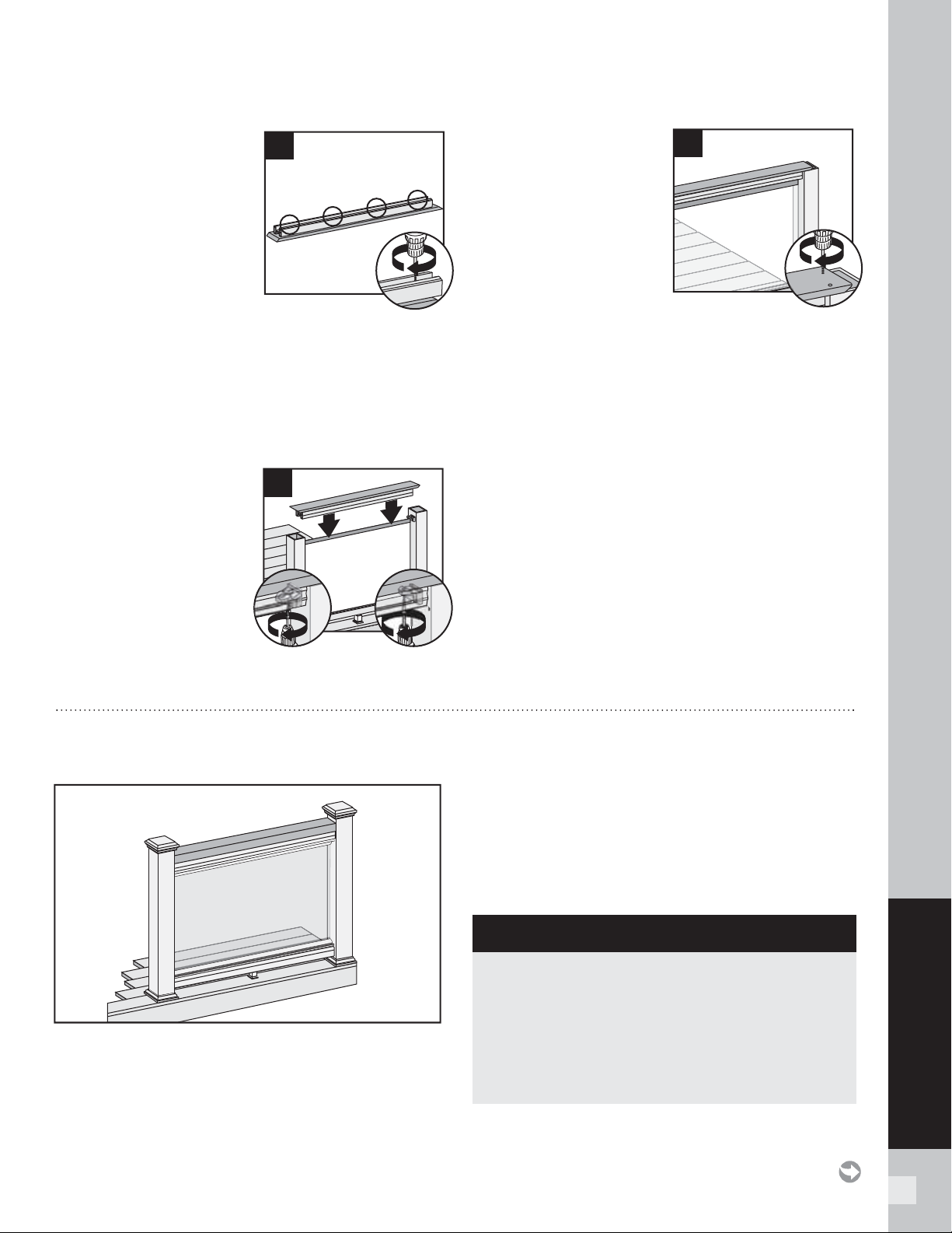
67
TRANSCEND RAILING
HOW TO ATTACH COCKTAIL STYLE GLASS PANEL RAILING/CONTINUED
TREX TRANSCEND
12. Secure deck board to
Universal rail with 2" (51
mm) pan head screws (not
provided) approximately
every 16" (406 mm) on
center at an angle. (DO
NOT overtighten. Attach
from underside of railing
into bottom of decking
board.)
IMPORTANT NOTES:
»
If using Select decking, USE maximum length 1-3/4"
(45 mm) screw and NOT 2" (51 mm) screw.
»
Screws that are used for attachment of decking board
to railing MUST be attached at angle to prevent screw
from penetrating through top of decking board.
13. Place inverted Universal
rail with deck board
attached onto RSB’s
with glass panel in
the channel. Attach
Universal rail to RSB’s
with three self-tapping
screws provided (use
three outer holes; do
not use hole in RSB that
is closest to post). If two hole bracket is included,
attach with two self-tapping holes (provided).
14. Attach deck board
to post (ensure that
screws are attached
to wood post) with
Trex recommended
composite screws
(quantity of 2 per each
board end).
15.
Attaching Panel
Support Moldings
See instructions on page 65.
16-17.
Hiding Brackets See instructions on page 65.
12
1
1
13
2
3
Hole
RSB
2
2
Hole
RSB
14
NOTES: Read all instructions BEFORE installation.
» You must purchase the 1/4" (6 mm) tempered glass
panels. See dimensions below.
» Glass panels ONLY for use with maximum 6'
(1.83 m) on center post spacing.
» NOT recommended for stair applications.
HOW TO ATTACH TRADITIONAL STYLE GLASS PANEL RAILING
TREX TRANSCEND
TEMPERED GLASS PANEL DIMENSIONS
» 36" (914 mm) high rail:
1/4" x 30" x 63-1/2" max.
(6 mm x 762 mm x 1613 mm)
» 42" (1067 mm) high rail:
1/4" x 36" x 63-1/2" max.
(6 mm x 914 mm x 1613 mm)
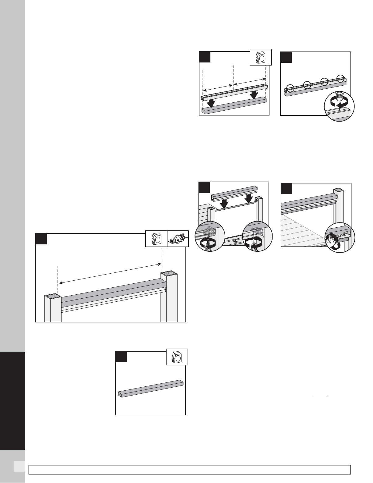
68
TRANSCEND RAILING
NOTE: Construction methods are always improving. Please refer to www.trex.com for the most up-to-date installation requirements.
1. Installing Pressure-Treated Posts
See instructions on page 59.
2.
Installing Post Sleeve Skirts and Post Sleeves
See instructions on page 59.
3.
Installing Railing Support Brackets (RSBs)
See instructions on page 59.
4.
Cutting Railings
See instructions on page 60.
5.
Attaching Foot Block
See instructions on page 60.
6.
Attaching Bottom Rail (Universal Rail), Adding
Weep Holes
See instructions on page 60.
7-8.
Attaching Weatherstripping and
Positioning Panel
See instructions on page 65.
Attaching Top Rail
9. Cut 2" x 4" (51 mm x 102 mm) to same length of the
inverted Universal rail.
10. Place inverted 2" x 4" (51
mm x 102 mm) (place
top side down) on clean,
fl at surface.
11. Place Universal rail (remembering to orient this
properly so that when fl ipped over, the Universal rail
will accept the baluster spacer and balusters), on the
2" x 4" (51 mm x 102 mm), centered.
12. Secure 2" x 4" (51 mm x 102 mm) to Universal rail
with 2" (51 mm) pan head screws (not provided)
approximately every 16" (406 mm) on center.
13. Place inverted Universal rail with 2" x 4" (51 mm x
102 mm) attached onto RSB’s with glass panel in the
channel. Attach Universal rail to RSB’s with three
self-tapping screws provided (use three outer holes;
do not use hole in RSB that is closest to post). If two
hole bracket is included, attach with two self-tapping
holes (provided).
14. Pre-drill a pilot hole and toenail 2-1/2" (64 mm)
composite deck screw (not provided) at each end of
the 2" x 4" (51 mm x 102 mm) into post on back side
(side not facing decking).
15.
Attaching Panel Support Moldings
See instructions on page 65.
16-17.
Hiding Brackets
See instructions on page 65.
18.
Attaching Post Caps and Installing New Foot
Block
See instructions on page 61.
11
10
9
12
1
1
13
2
3
Hole
RSB
2
2
Hole
RSB
14
3
HOW TO ATTACH TRADITIONAL STYLE GLASS PANEL RAILING/CONTINUED
TREX TRANSCEND
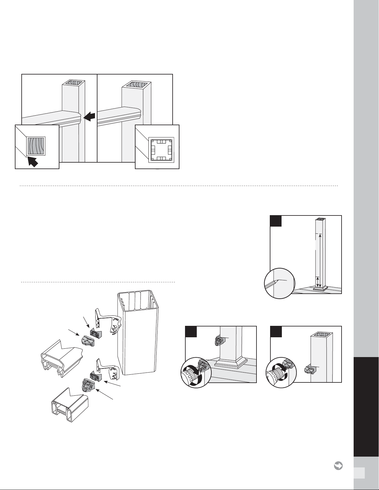
69
TRANSCEND RAILING
HOW TO INSTALL ON-AN-ANGLE RAILING
TREX TRANSCEND (CROWN AND UNIVERSAL RAILING)
NOTE: Trex railing brackets are designed to be installed
up to a 45° angle.
» Small angles (1° - 30°). Both 4" x 4" (102 mm x
102 mm) or 6" x 6" (152 mm x 152 mm) post sleeves
work well.
» Large angles (31° - 45°). USE ONLY 6" x 6"
(152 mm x 152 mm) post sleeves when installing on
fl at side.
» 45° angles using 4" x 4" (102 mm x 102 mm) post
sleeves MUST use Transcend Bird’s Mouth brackets.
NOTE: Railing will be installed on corner of posts.
» Using 6" x 6" (152 mm x 152 mm) post sleeves at
45° angles. Brackets are installed off-center and use
45° Transcend gaskets.
» Railing gaskets are designed to fi t at 0°, 22.5°, and 45°
angles. Gaskets are labeled with appropriate angle
dimension.
4 x 4 6 x 6
HOW TO INSTALL CROWN AND UNIVERSAL BIRD'S MOUTH RAILING
TREX TRANSCEND
NOTES:
» Use with 4" x 4" (102 mm x 102 mm) post sleeve ONLY.
» Gaskets are only designed for use with Transcend
Crown and Universal Railing.
Read all instructions BEFORE installation.
PARTS
Mark Posts
1. Measure and mark
4 " (102 mm) and
3 3 - 9 / 1 6 " (852 mm) up
from top of post skirt.
NOTE: Without skirt,
add 1-1/2 " (38 mm) to
measurements.
Attaching Adapters Snap
adapters into RSBs.
Pre-drill Bottom and Top RSBs
2. Position RSBs with adapter (fl at side DOWN) for
lower rail, mark and pre-drill screw holes with
1/8 " (3 mm) drill bit on post.
3. Position RSBs with adapter (fl at side UP) for top rail,
mark and pre-drill screw holes with 1/8 " (3 mm) drill
bit on post.
Top bracket
Adapter
Adapter
Bottom bracket
1
4"
(102 mm)
33-9/16"
(852 mm)
for 36"
(914 mm)
33-9/16"
(852 mm)
for 36"
(914 mm)
2
3
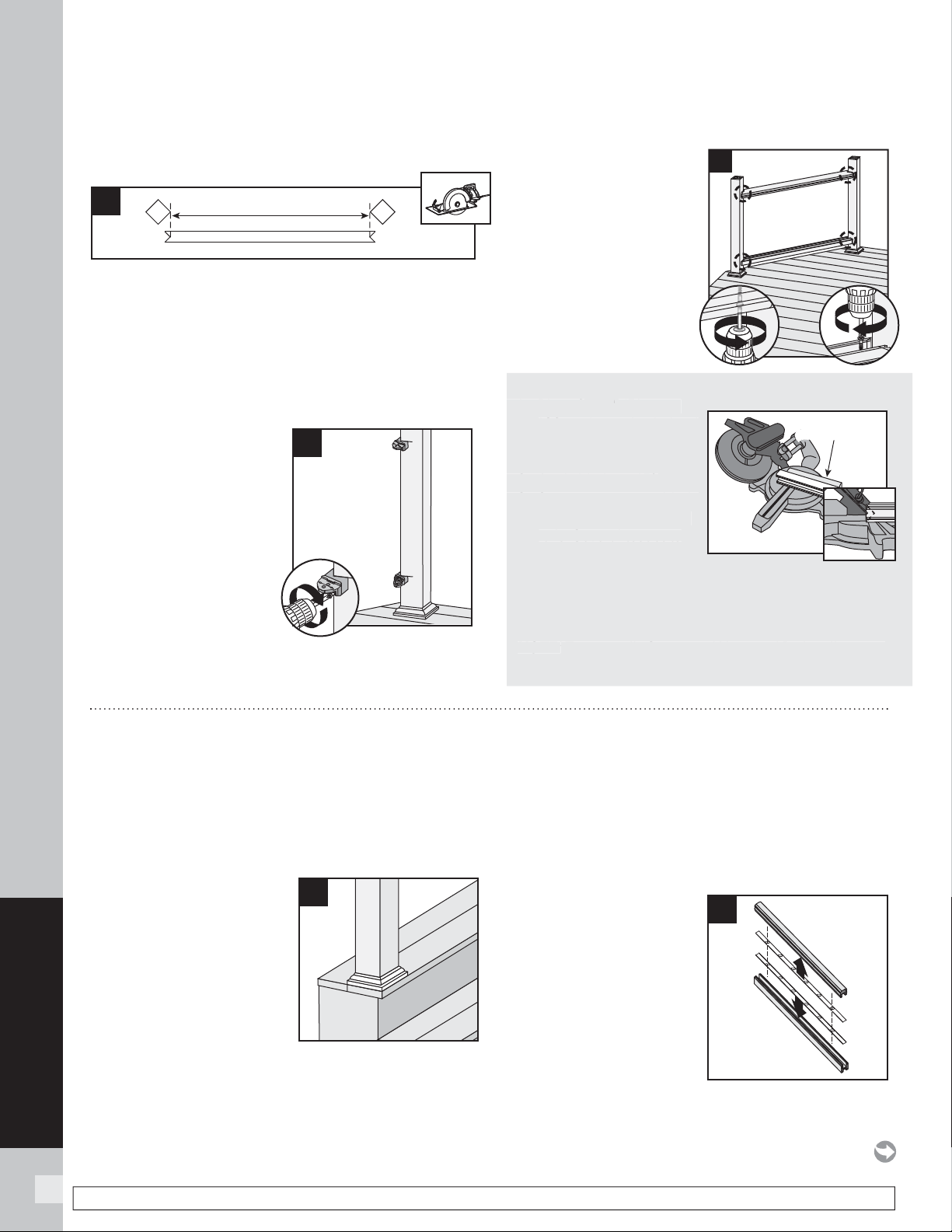
70
TRANSCEND RAILING
NOTE: Construction methods are always improving. Please refer to www.trex.com for the most up-to-date installation requirements.
Measuring and Cutting Rails
4. Measure from corner-to-corner between posts. Mark
45° cuts on rails with template on assembly tool.
Center of “V’s” is the distance from corner-to-corner
for posts.
NOTE: Subtract 1/16" (1.6 mm) from each end to
accommodate rail gaskets.
Attaching Top and
Bottom RSBs
5. Attach RSBs with
adapters to posts with
wood screws (provided).
N
OTES:
» Drill at slight inward angle
to drill holes on marks.
» Lay cut lower rail into
position on decking
surface between the posts
before attaching the lower RSB. There may be some
diffi culty attaching the lower rail if you fail to do this.
Installing Railings to
RSB's
6. Attach with self-tapping
screws (provided).
Using Miter Box Saw to Cut Rails
1. Place 2" x 4" (51 mm x
102 mm) on edge behind
the rail to allow for
complete cut.
2. Angle blade to 45°.
3. Set stop on saw so blade
travels half the depth of
rails. Several test cuts
can be made on scrap
material to accurately
set the stop.
4. “V” cut both sides of the rail.
NOTE: Transcend's Crown and Universal Rails will require
different stop settings.
4
5
6
Usin
g
Miter Box Saw to Cut Rails
1. Pla
ce
2
"
x 4
"
(
51 mm x
102 mm
)
on edge behind
t
h
e
rail t
o
all
o
w
fo
r
com
p
lete cut
.
2. Angle blade to 45°
.
3. Set sto
p
on saw so blade
t
ravels hal
f
the de
p
th o
f
r
ails.
S
everal test cuts
can be made on scra
p
m
aterial to accurately
set the sto
p
.
4. “V”
cu
t b
o
th sid
e
s
of
th
e
rail.
N
O
TE
:
Transcend's
C
rown and Universal Rails will require
different stop settings.
2" x 4"
(5.1 cm x 10.2 mm)
2" x 4"
(51 mm x 102 mm)
1
2a
HOW TO INSTALL CROWN AND UNIVERSAL STAIR RAILING
TREX TRANSCEND
HOW TO INSTALL CROWN AND UNIVERSAL BIRD'S MOUTH
RAILING/
CONTINUED
TREX TRANSCEND
Read all instructions BEFORE installation.
NOTE: All Transcend railings and gaskets work ONLY
WITH STAIR SLOPES OF 32°-37°.
Installing Posts, Post
Sleeve Skirts, and Post
Sleeves for Stair Rails
1. Install posts, post sleeve
skirts, and post sleeves
according to standard
Transcend railing
instructions.
See page 59.
» In most cases, a post and post sleeve longer than
39" (991 mm) will be needed on the lower section of
stair rail to accommodate stair angle.
» Make sure top and bottom posts for stairs are
installed at nose of each tread.
Measuring and Cutting
Railings
2a. Snap baluster spacers
into top and bottom
railings, ensuring the
baluster spacer holes
line up parallel.
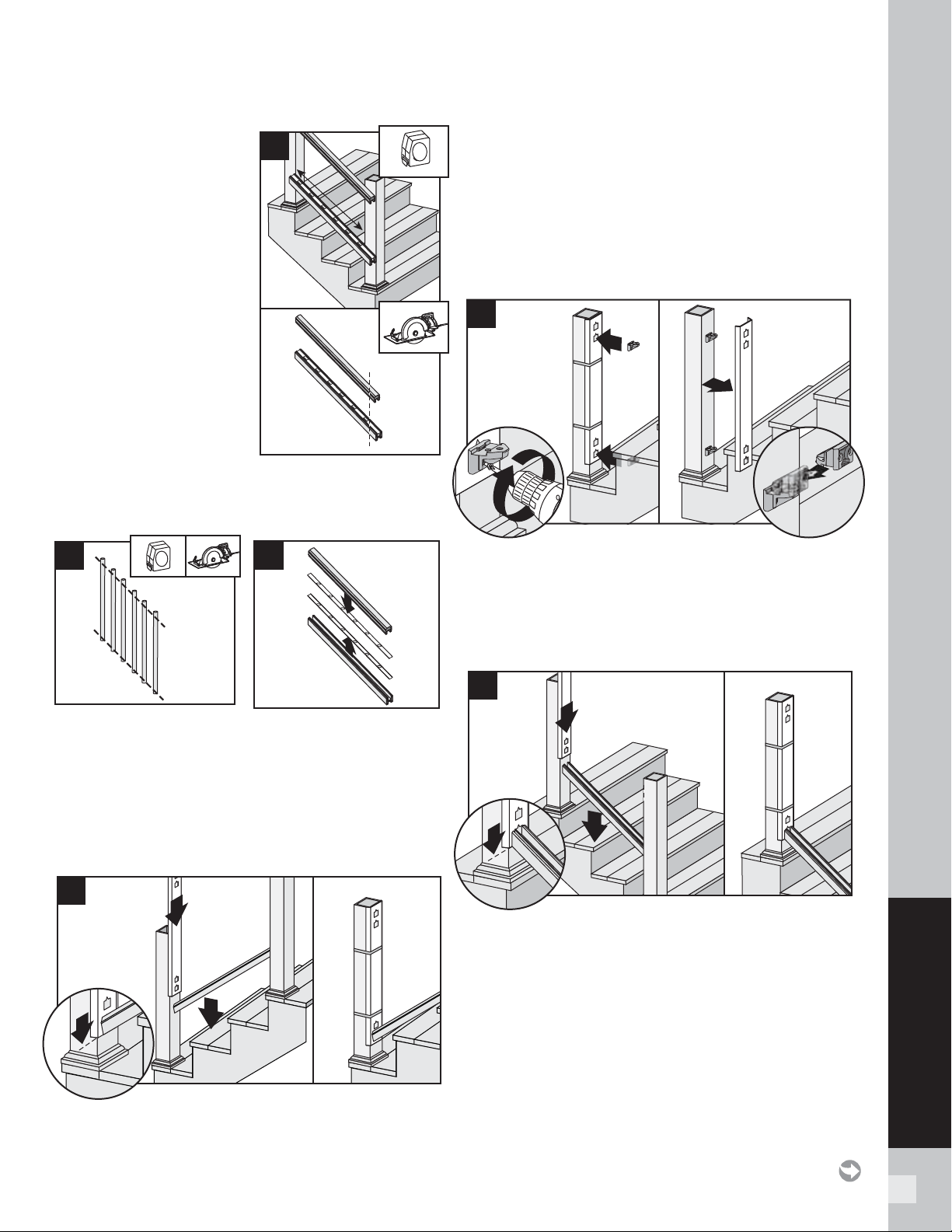
71
TRANSCEND RAILING
2b. Set bottom and top rail
along the nose of the
stair treads, ensuring
baluster holes are placed
evenly. Also allow for
a minimum of 1 1/2"
at each end of rail for
bracket placement and
baluster clearance. Cut
rails on marks.
NOTES:
» If using railing gaskets,
subtract 1/16" (1.6 mm)
maximum, from each end
and cut.
» CUT VERY CAREFULLY
TO NOT BREAK
BALUSTER SPACERS.
Cutting Balusters on Angle (OPTIONAL)
2c. In order for balusters to seat properly (depending on
the angle of the stair railing), the balusters may need
to be trimmed to match the angle of the bottom and
top railing.
2d. Carefully remove baluster spacers from rails.
Positioning RSBs on BOTTOM Post
3. Position bottom rail between posts and slide
TrexE xpress
™
railing assembly template into position
with bottom rail outline on template aligned with end
of bottom rail. Allow a minimum clearance of 1"
(25 mm) from stair tread. Secure template with
rubber bands. Remove rail.
Attaching RSBs to BOTTOM Post
4. Attach upper and lower RSBs to bottom post,
fl at side UP, with wood screws provided. Remove
template and place a second RSB, turned upside
down, and interlock on each bracket.
Positioning RSBs on UPPER Post
5. Position pre-cut bottom rail between posts. Slide
TrexE xpress
™
railing assembly template into position,
aligning bottom rail outline on template with end of
bottom rail. Use rubber bands to hold template in
place. Remove rail.
2c
2b
HOW TO INSTALL CROWN AND UNIVERSAL STAIR RAILING/CONTINUED
TREX TRANSCEND
2d
1
2
1
3
3
3
1
1
4
2
2
1
5
3
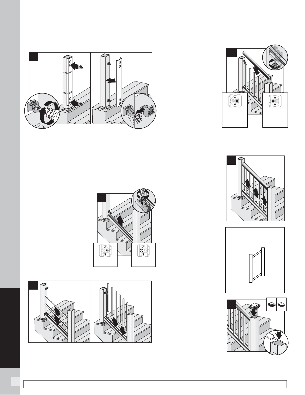
72
TRANSCEND RAILING
NOTE: Construction methods are always improving. Please refer to www.trex.com for the most up-to-date installation requirements.
Attaching RSBs to UPPER Posts
6. Attach upper and lower RSBs to top post, fl at side
DOWN. Remove template. Take second RSB, turn
upside down and interlock into each bracket.
If Attaching Original Foot Block to Bottom Rail
7a. See detailed instructions included with foot block.
If Attaching New Foot Block to Bottom Rail
7b. See detailed instructions included with foot block.
Attaching Bottom Rail
(Universal Rail)
8. Lift bottom rail so RSB's
are in the channel and
attach with 3 self-tapping
screws (provided). Use
the three outer holes in
RSB to attach screws.
Adding Weeping Holes
9.
See instructions on page
60.
Placing Baluster Spacers and Balusters
10. Snap baluster spacer into bottom rail. Place
inverted baluster spacer on top of fi rst baluster
spacer making sure that holes line up parallel. Place
balusters in baluster spacer holes.
Attaching Top Rail
11a. Place top rail of
choice (Crown rail
shown here) on
RSB's in rail channel
and attach with 3
self-tapping screws
(provided). Use the
three outer holes
in RSB to attach
screws.
11b. If installing a
different railing
confi guration
other than Crown Railing, refer to other Railing
Confi gurations in Horizontal sections for additional
requirements.
12. Slide baluster spacer up
and snap into top rail.
Attaching Optional
Gaskets
13. Stair railing gaskets
are designed to fi t at
slopes of 32° to 37°.
Gaskets are labeled
in order to ensure
correct location.
Attaching Post Caps
and Installing New Foot
Block
14. Secure post caps
with silicone or PVC
adhesive. Attach new
foot block per foot
block instructions.
NOTE: Clean-up any excess
adhesive before drying.
HOW TO INSTALL CROWN AND UNIVERSAL STAIR RAILING/CONTINUED
TREX TRANSCEND
3
1
1
6
4
2
Universal Rail
Stair Gasket
Locations
STR T2 B1
STR T1 B2
STR T1 B2
STR T2 B1
2
14
3
1
1
8
2
Upper Post
Location -
Bottom Rail
Lower Post
Location -
Bottom Rail
1
11a
Upper Post
Location -
Top Rail
(view from
under rail)
(view from
under rail)
Lower Post
Location -
Top Rail
3
3
1
2
10
12
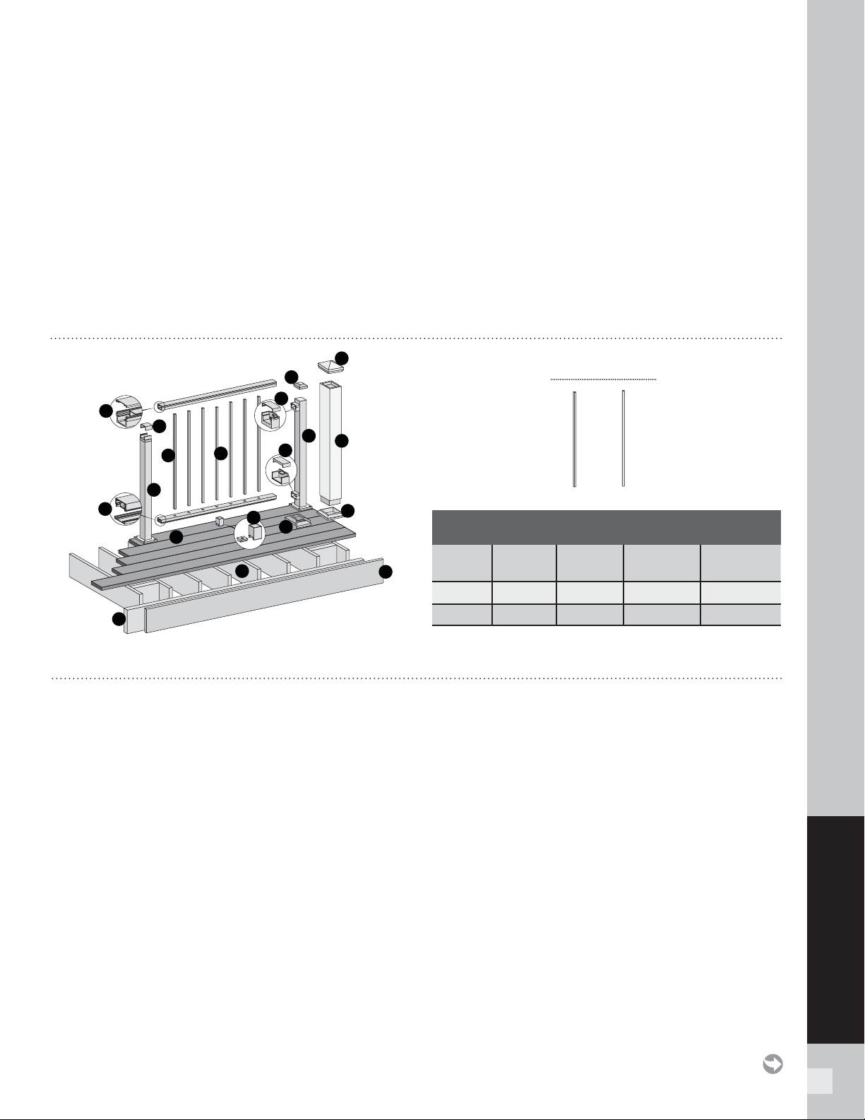
73
SIGNATURE RAILING
TREX SIGNATURE
®
(FORMERLY REVEAL
®
) RAILING
NOTES:
» SIGNATURE POSTS CANNOT BE USED WITH SIGNATURE TRADITIONAL OR SIGNATURE COCKTAIL DESIGNS, ONLY PRESSURE-TREATED POSTS/
POST SLEEVES CAN BE USED. REFER TO DETAILED INSTRUCTIONS FOR MORE INFORMATION.
» SIGNATURE RAILINGS ARE DESIGNED TO BE ATTACHED WITH POSTS INSTALLED AT A CLEAR SPAN OF 6' (1.83 M) OR 8' (2.44 M).
» IF INSTALLING AT EXACT SPAN LENGTHS OF 6' (1.83 M) OR 8' (2.44 M), AND USING POST-TO-POST CONFIGURATION, THE BOTTOM RAIL WILL NOT
NEED TO BE CUT, BUT THE TOP RAIL WILL NEED TO BE MEASURED (MAKING SURE BALUSTERS LINE UP VERTICALLY) AND CUT.
» IF INSTALLING AT EXACT SPAN LENGTHS OF 6' (1.83 M) OR 8' (2.44 M), AND USING CROSSOVER POST CONFIGURATION (SPANS FROM ONE
CROSSOVER POST TO ANOTHER CROSSOVER POST), BOTH THE BOTTOM RAIL AND TOP RAIL WILL NOT NEED TO BE CUT.
» IN ADDITION, AT ALL FINAL END POST CONFIGURATIONS, TOP RAIL WILL NEED TO BE MEASURED (MAKING SURE BALUSTERS LINE UP
VERTICALLY) AND CUT.
» SEE INFORMATION WITHIN DETAILED INSTRUCTIONS FOR MORE INFORMATION.
» SEE PAGE 54 FOR SKU NUMBERS.
G
C
I
A
D
K
L
J
E
B
H
H
I
K
M
N
O
P
F
Square Round
BALUSTER OPTIONS
DETERMINING BALUSTERS NEEDED
Baluster
Type
Per 6'
Section
Per 8'
Section
Per 6' Stair
Section
Per 8' Stair
Section
Square 15 20 13 17
Round 15 20 13 17
A. Signature top rail and crowned cover
- 6' (actual length 73.5" [186.7 cm])
- 8' (actual length 97.5" [247.7 cm])
B. Signature bottom rail and fl at cover
- 6' Rail (actual length 71.5" [181.6 cm])
- 6' Cover (actual length 70.0" [177.8 cm])
- 8' Rail (actual length 95.5" [242.6 cm])
- 8' Cover (actual length 94.0" [238.8 cm])
C. Signature upper rail bracket and cover
D. Signature lower rail bracket and cover
E. Signature balusters (square or round)
F. Signature center baluster (square or round)
G. Signature foot block**
H. Signature post skirt or post sleeve skirt*
I. Signature post*
(2" or 2.5" depending on application)
- 36" (actual length 37" [94.0 cm])
- 42" (actual length 43" [109.2 cm])
or Trex 4" x 4" post sleeve*
- 36" (actual length 39" [99.1 cm])
- 42" (actual length 45" [114.3 cm])
NOTE: MUST USE TREX DECK MOUNT POST HARDWARE
AND METAL PLATE WHEN ATTACHING SIGNATURE POSTS.
NOTE: THIS IS AN OVERVIEW OF ALL RAILING COMPONENTS FOR SIGNATURE HORIZONTAL APPLICATIONS – REFER TO DETAILED INSTRUCTIONS
FOR SPECIFIC RAILING CONFIGURATIONS.
J. Signature crossover post*
- 36" (actual length 34.5" [87.6 cm])
- 42" (actual length 40.5" [102.9 cm])
K. Signature post cap or post sleeve cap*
L. Trex decking
M. Trex Fascia
N. Code-approved wood joist 2" x 8"
(5.1 cm x 20.3 cm) or larger
O. Code-approved wood rim joist 2" x 8"
(5.1 cm x 20.3 cm) or larger
P. Crossover bracket cover (supplied with crossover post)
* Item not included in Signature Railing kits. Both 4" x 4" (10.2 cm x
10.2 cm) and 6" x 6" (15.2 cm x 15.2 cm) post sleeves are designed to fit
over 4" x 4" pressure-treated post.
** Required ONLY for All Clear Span Applications over 6' (1.83 m) when
smaller fixed baluster is fully centered, or unsupported spans greater than
5' (1.52 m) (example: 8' (2.44 m) span cut into one 5' (1.52 m) span and
one 3' (0.91 m) span would require foot block under 5' (1.52 m) span since
smaller fixed baluster is no longer centered). Included with 8' (2.44 m)
railing kits.
NOTE: If installing 42" (106.7 cm) railing, and using pressure-treated posts with Trex
post sleeves, ensure that a longer pressure-treated post is used along with longer
post sleeve, both cut to a height of 46" (116.8 cm) from decking surface.
PARTS
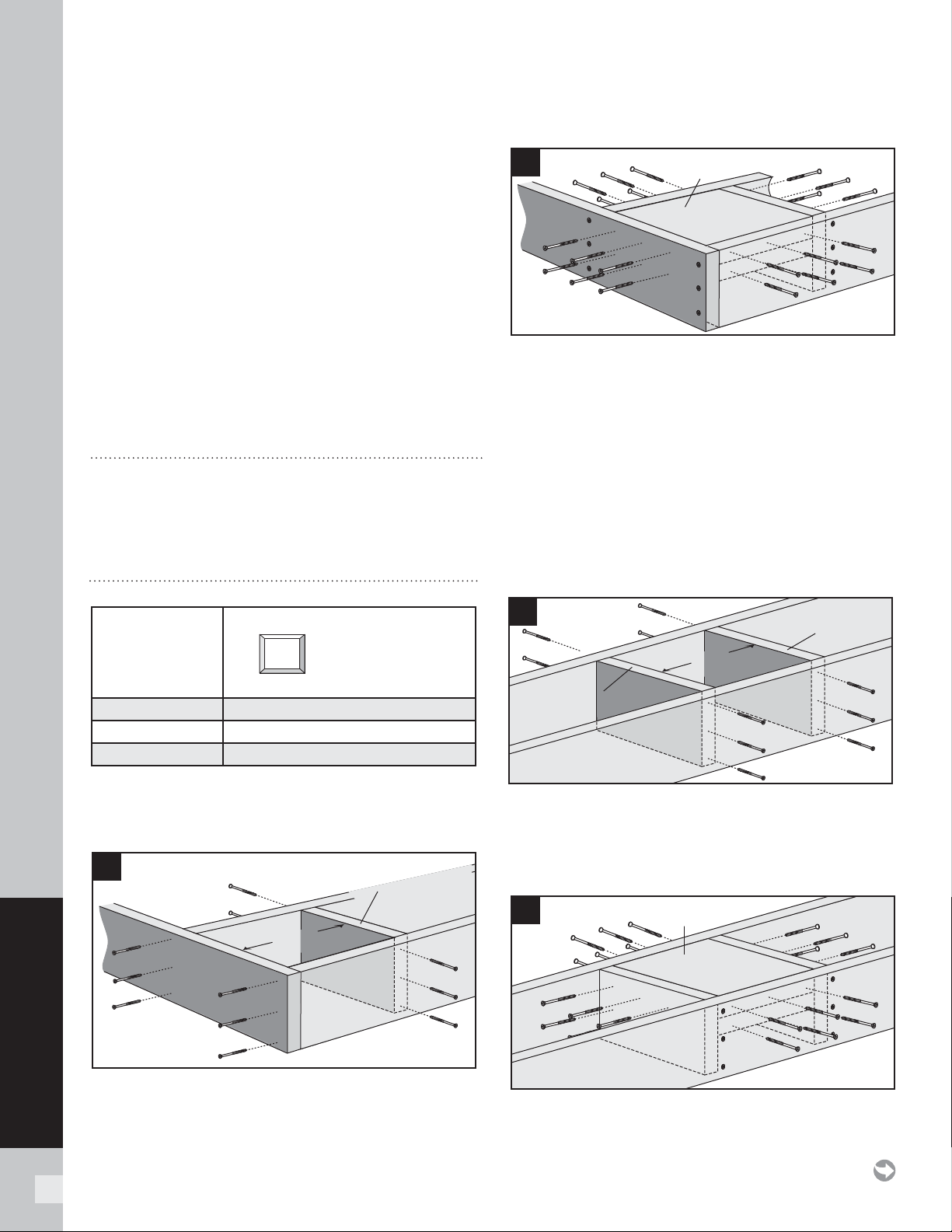
74
SIGNATURE RAILING
IMPORTANT NOTES:
» EACH POST MUST BE ATTACHED AS SHOWN TO ENSURE A CODE-
COMPLIANT AND SAFE INSTALLATION.
» SIGNATURE POSTS CANNOT BE USED WITH SIGNATURE TRADITIONAL
OR SIGNATURE COCKTAIL DESIGNS, ONLY Pressure-treated POST/POST
SLEEVES CAN BE USED. REFER TO DETAILED INSTRUCTIONS FOR MORE
INFORMATION.
» ALWAYS refer to your local building code official prior to installing
any railing system to ensure all code and safety requirements are met.
Trex® cannot be held responsible for improper or non-recommended
installations.
» When installing Signature posts on ACQ, CCA or concrete surfaces, use
an appropriate isolation barrier between post and surface (contact local
building code official if needed).
» For installing Signature Post and/or Signature Crossover Posts, see below.
» For pressure-treated posts, post sleeves, and skirts, see detailed
instructions provided with Signature Railing Kits.
» All Signature stair installations require the use of a 53" (1346 mm) stair
post, measured and cut to appropriate length if necessary.
» If crossover stair post is required, use stair post (again cut to
appropriate length if necessary) and use swivel crossover bracket.
» If installing on concrete, make sure all surfaces are level.
TOOLS AND MATERIALS NEEDED
»
Drill and/or screw gun (hammer drill for concrete)
»
1/2" (13 mm) drill bit for wood, 3/8" (10 mm) drill bit for concrete
»
Blocking – 2" x 8" (51 mm x 203 mm) pressure-treated Southern
Yellow Pine or equivalent
»
Qty: 36 (per post) – 3" pressure-treated compatible wood screws
CODE APPROVED POST APPLICATIONS
POST SIZE
< 30" height decking Acceptable (Code Approval not Applicable)
IRC Compliant Yes
IBC Compliant No
Installing Signature Posts and/or Signature
Crossover Posts on Pressure-treated Wood
Framing
(Corner Post Installation)
1. Install 2" x 8" (51 mm x 203 mm) cross bracing
frame in between joists at 7-1/4" (184 mm).
Attach
a total of twelve 3
"
(76 mm) pressure-treated
compatible screws (not provided).
2. Install two 2" x 8" (51 mm x 203 mm) boards as
blocking under post location. Securely attach
blocking using a total of twenty-four
3
"
(76 mm)
pressure-treated compatible screws (not provided).
NOTE: TO ENSURE THE BLOCKING IS FULLY SECURE,
USE THE AMOUNT OF SCREWS INDICATED ABOVE.
TIP: Use two additional screws to "sandwich" blocking
boards together for easier attachment to framing.
Line Post Installation
3. Install two 2
"
x 8
"
(51 mm x 203 mm) cross bracing
frames in between joists at 7-1/4
"
(184 mm). Attach
a total of twelve 3
"
(76 mm) pressure-treated
compatible screws (not provided).
4. Install two 2
"
x 8
"
(51 mm x 203 mm) boards as
blocking under post location. Securely attach
blocking using a total of twenty-four 3
"
(76 mm)
pressure- treated compatible screws
(not provided).
7-1/4
"
(18.4 cm)
7-1/4"
(18.4 cm)
2" x 8" Pressure-treated
Cross bracing frame
1
2
Blocking
boards
7-1/4"
(18.4 cm)
7-1/4
"
(18.4 cm)
3
Cross bracing
frame
Cross bracing
frame
4
Blocking
boards
2.5" (64 mm)
2.5" (64 mm)
2.5 x 2.5 (64 mm x 64 mm) Post (IRC)
INSTALLING SIGNATURE POSTS AND/OR SIGNATURE CROSSOVER
POSTS ON WOOD OR CONCRETE
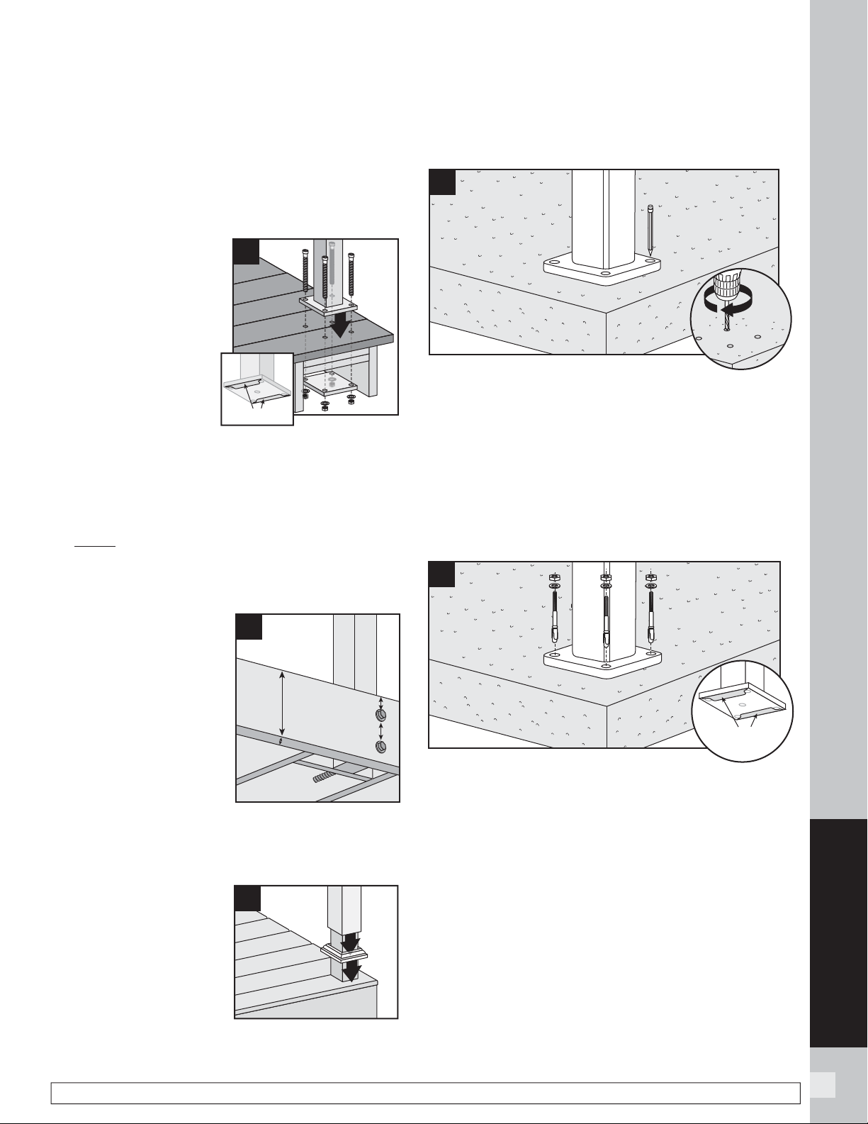
75
SIGNATURE RAILING
NOTE: Construction methods are always improving. Please refer to www.trex.com for the most up-to-date installation requirements.
NOTES:
» Rim joist removed to show proper attachment of
hardware.
» Metal backplate is only required for 2.5" (64 mm)
post in IRC installations. (Consult local code offi cial for
more information.)
5.
Insert (2) stainless
steel barrier strips
under mounting
bolt holes. Use
composite shims or
similar material (not
provided) if posts are
not plumb. Ensure
that post is placed on
decking surface so it
clears rim joist and
there is enough clearance on underside blocking
for back plate to be installed. Attach posts using
four 3/8" x 6" (10 mm x 152 mm) hex cap bolts,
washers, and nuts, along with using aluminum
back plate on underside of blocking (back plate
only required for 2.5" [64 mm] posts). Back plate
MUST be installed under decking to ensure this will
meet code compliance. Reference Trex SKU part
number ALPOSTHWDECK for required hardware and
aluminum plate.
Installing Pressure-
treated Posts, Post
Sleeves, and Skirts to
Use with Signature
Railing
6. Attach posts using 1/2"
(13 mm) carriage bolts.
» Minimum joist size is 2" x
8" (51 mm x 203 mm).
» Top bolts must be 1"
(25 mm) from top of
joists.
» Bottom bolts must be 5-1/8" (130 mm) from top bolts.
NOTE: Blocking can be added for extra strength.
7. Slide post sleeve skirt
over post and down
to rest on decking
surface. Slide post
sleeve over post and
position inside post
sleeve skirt.
NOTE: Shims can be used
to plumb post sleeves.
Installing Reveal Posts on Concrete
Pre-drill Holes Pre-drill Hole
1. Using post as a template, mark locations of the four
holes and drill into concrete at least 2-5/8" (67 mm)
using a 3/8" (10 mm) masonry bit.
NOTE: You can either set drill bit to correct depth on
drill or mark drill bit with tape at required dimension to
ensure all holes are drilled at correct depth.
2. Clean out holes to remove all concrete dust using a
shop vacuum or other appropriate tool.
3. Insert (2) stainless steel barrier stripes under
mounting bolt holes. Use appropriate shims if
posts are not plumb. Attach posts using four
TREX SUPPLIED 3/8" x 3-3/4" (10 mm x 95 mm)
wedge anchors. Reference SKU part number
ALPOSTHWCONC for required hardware (wedge
anchors, washers, and nuts).
NOTES:
»
When using hammer to tap anchors in place, keep
threaded nut at top of anchor in order to not damage
threads.
» Recommended torque for anchors is 20 ft-lbs.
5
barrierbarrier
1
2
7
6
5-1/8" (130 mm) min.
2" x 8"
(51 mm x
203 mm)
min.
1" (25 mm) min.
1
3/8"
(10 mm)
3
BarrierBarrier
INSTALLING SIGNATURE POSTS AND/OR SIGNATURE CROSSOVER
POSTS ON WOOD OR CONCRETE/
CONTINUED
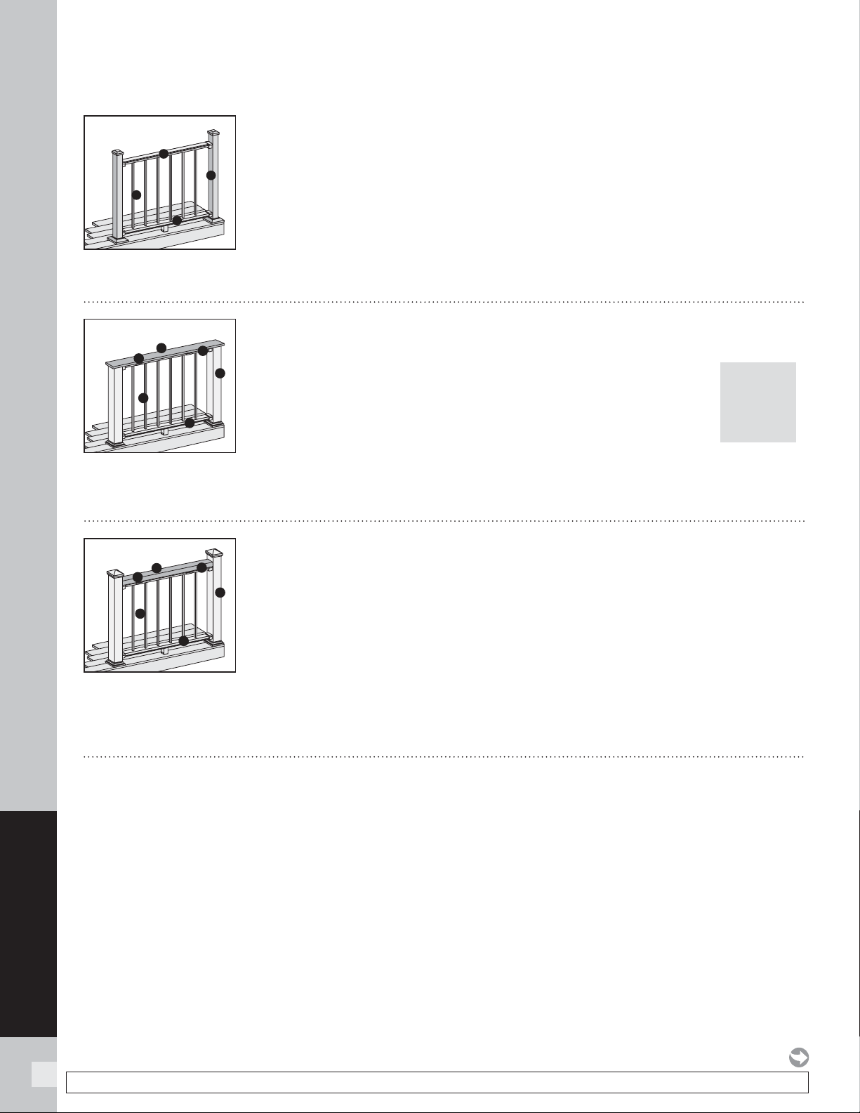
76
SIGNATURE RAILING
NOTE: Construction methods are always improving. Please refer to www.trex.com for the most up-to-date installation requirements.
POST
SLEEVES
WILL
NEED TO
BE CUT
TREX SIGNATURE
RAILING CONFIGURATIONS
Cutting posts/post sleeves is NOT required.
A. Signature post, pressure-treated post or Trex Post Mounts* with Trex Transcend post
sleeves, or Trex Joist Mount Posts*.
B. Signature top rail
C. Signature bottom rail
D. Signature balusters
See page 78 for “How to Install Standard Railing”.
*NOTE: See specifi c installation instructions for attachment of Trex post mounts or Trex
Joist Mount Posts prior to installing any railing.
Cutting posts/post sleeves is NOT required.
A. Pressure-Treated post with Trex Transcend post sleeve
NOTE: » Only for use with 4" x 4" (102 mm x 102 mm) or 6" x 6" (152 mm x 152 mm)
post sleeve
» Trex Signature Posts, Trex Post Mounts or Joist Mount Posts cannot be
used with Signature Traditional design
B. 2" x 4" (51 mm x 102 mm) lateral top rail
C. Signature top rail
D. Signature bottom rail
E. Signature balusters
F. Signature Cocktail Rail Bracket**
See page 88 for “How to Install Signature Traditional Railing”.
Post sleeves WILL NEED TO BE CUT.
A. Pressure-treated post with Trex Transcend post sleeve
NOTE: » Only for use with 4" x 4" (102 mm x 102 mm) post sleeve.
» Trex Signature Posts, Trex Post Mounts or Joist Mount
Posts cannot be used with Signature® Cocktail design.
B. Deck board top rail. NOTE: Contour and Escapes cannot be used.
C. Signature top rail
D. Signature bottom rail
E. Signature balusters
F. Signature Cocktail Rail Bracket**
See page 87 for “How to Install Signature Cocktail Railing”.
A
B
C
D
A
B
D
C
E
F
A
B
D
C
E
F
Standard
Cocktail
Traditional
** Signature Cocktail Rail brackets (sold separately) are for use with either Signature Traditional or Signature Cocktail designs. For a 6' section, use 4
brackets and screws provided, for 8' section, use 5 brackets and screws provided.
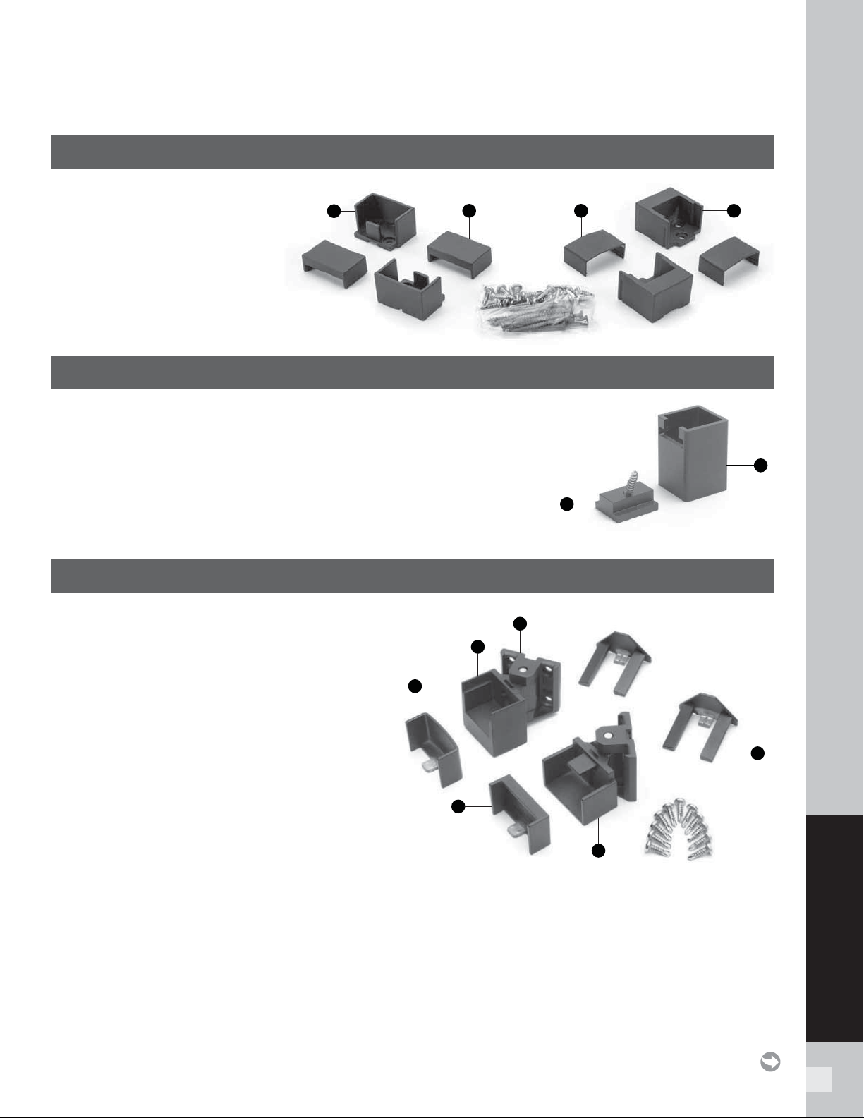
77
SIGNATURE RAILING
BRACKET HARDWARE – HORIZONTAL APPLICATIONS
(INCLUDING HORIZONTAL SWIVEL BRACKETS)
TREX SIGNATURE
HORIZONTAL RAILING HARDWARE
AA. Lower rail bracket
BB. Lower rail bracket cover
CC. Upper rail bracket cover
DD. Upper rail bracket
FOOT BLOCK COMPONENTS
EE. Foot block base
FF. Foot block support
HORIZONTAL SWIVEL HARDWARE
GG. Swivel base
HH. Horizontal swivel bracket top rail
II. Horizontal swivel bracket top rail cover
JJ. Horizontal swivel bracket bottom rail cover
KK. Horizontal swivel bracket bottom rail
LL. Swivel base cover
FF
EE
GG
LL
KK
JJ
II
HH
AA
BB
CC
DD
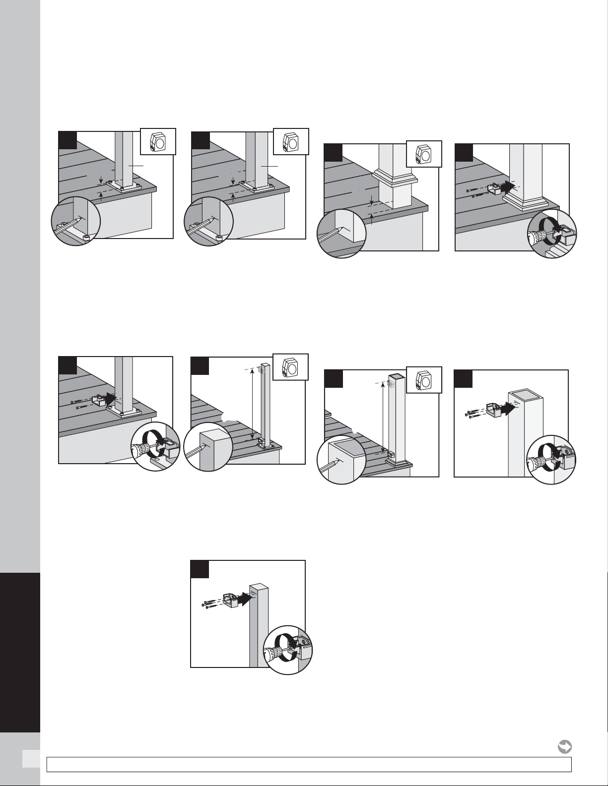
78
SIGNATURE RAILING
NOTE: Construction methods are always improving. Please refer to www.trex.com for the most up-to-date installation requirements.
HOW TO INSTALL HORIZONTAL RAILING
TREX SIGNATURE
STANDARD
Attach Brackets Using Signature Posts
TIP: Use a clamp to help hold brackets in place while
fastening with screws.
1a. If using 2" post, for both post-to-post and
post-to-crossover post confi gurations, measure
1-1/2" (3.8 cm) up from top of post base plate
(or 1-7/8" [4.8 cm] from decking surface). Mark
with light line.
1b. When using 2.5" post, measure 1-3/8" (3.5 cm)
from top of post base plate or 1-7/8" (4.8 cm) from
decking surface. Mark with light line.
2. Center lower bracket on post above the marked
line and attach using two self-tapping screws
(provided).
3. Measure up 32-5/8" (82.9 cm) for 36" (91.4 cm) tall
railing or 38-5/8" (98.1 cm) for 42" (106.7 cm) tall
railing from top of lower rail bracket. Mark with
a light line.
4. Center upper bracket
on post below marked
line and attach using
(3) self-tapping
screws (provided).
NOTE: Upper bracket is
not required on crossover
post confi guration.
Attach Brackets Using Pressure-treated Posts
and Post Sleeves
TIP: Use a clamp to help hold brackets in place while
fastening with screws.
5. Measure 1-7/8" (4.8 cm) up from deck surface
to bottom of bracket. Slide skirt up to allow for
proper measurement, then push skirt back down
onto surface of decking BEFORE ATTACHING
BRACKET. Mark with light line.
6. Center lower bracket on post above the marked
line and attach using two 2" (5.1 cm) wood screws
(provided).
7. Measure up 32-5/8" (82.9 cm) for 36" (91.4 cm)
tall railing or 38-5/8" (98.1 cm) for 42" (106.7 cm)
tall railing from top of lower rail bracket. Mark with
a light line.
8. Center upper bracket on post below marked line
and attach using three 2" (5.1 cm) wood screws
(provided).
32-5/8"
(82.9 cm)
or
38-5/8"
(98.1 cm)
32-5/8"
(82.9 cm)
or
38-5/8"
(98.1 cm)
7
1
8
2
1-1/2"
(3.8 cm)
1-1/2"
(3.8 cm)
2" Post2" Post
1a
1-3/8"
(3.5 cm)
1-3/8"
(3.5 cm)
2-1/2"
Post
2-1/2"
Post
1b
1
2
2
32-5/8"
(82.9 cm)
or
38-5/8"
(98.1 cm)
32-5/8"
(82.9 cm)
or
38-5/8"
(98.1 cm)
3
1
4
2
1-7/8"
(4.8 cm)
1-7/8"
(4.8 cm)
5
1
6
2
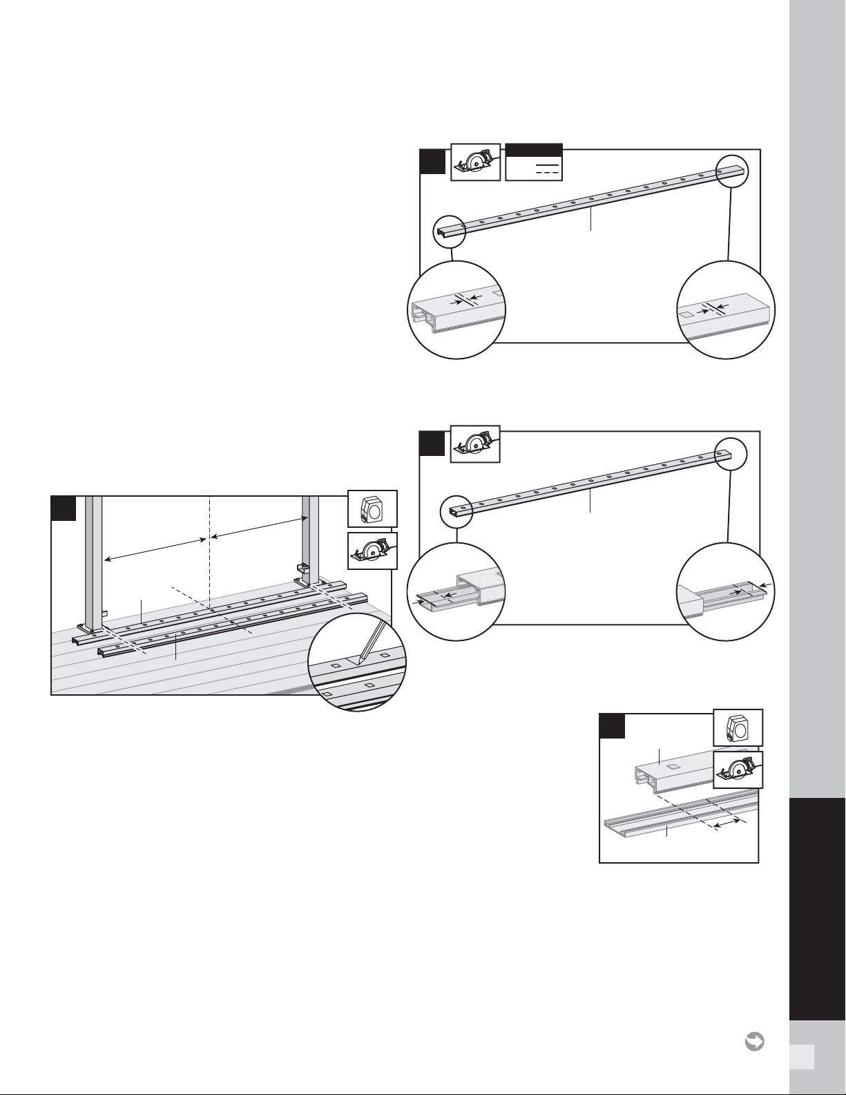
79
SIGNATURE RAILING
NOTES:
» SIGNATURE RAILINGS ARE DESIGNED TO BE ATTACHED WITH POSTS
INSTALLED AT A CLEAR SPAN OF 6' (1.83 M) OR 8' (2.44 M).
» IF INSTALLING AT EXACT SPAN LENGTHS OF 6' (1.83 M) OR 8'
(2.44 M), AND USING POST-TO-POST CONFIGURATION, THE BOTTOM
RAIL WILL NOT NEED TO BE CUT, BUT THE TOP RAIL WILL NEED TO BE
MEASURED (MAKING SURE BALUSTERS LINE UP VERTICALLY) AND CUT.
» IF INSTALLING AT EXACT SPAN LENGTHS OF 6' (1.83 M) OR 8'
(2.44 M), AND USING CROSSOVER POST CONFIGURATION (SPANS
FROM ONE CROSSOVER POST TO ANOTHER CROSSOVER POST), BOTH
THE BOTTOM RAIL AND TOP RAIL WILL NOT NEED TO BE CUT.
» IN ADDITION, AT ALL FINAL END POST CONFIGURATION, TOP RAIL
WILL NEED TO BE MEASURED (MAKING SURE BALUSTERS LINE UP
VERTICALLY) AND CUT.
» FOR ODD SPAN LENGTHS, BOTH TOP RAIL AND BOTTOM RAIL
WILL NEED TO BE MEASURED (MAKING SURE BALUSTERS LINE UP
VERTICALLY) AND CUT. ENSURE THAT BALUSTERS ARE SPACED WITH
AN EQUAL DISTANCE ON EACH SIDE OF THE POST.
» WHEN RAILINGS ARE CUT TO ODD SPANS, ALL SPANS GREATER THAN
5' (1.52 M) (EXAMPLE: 8' (2.44 M) SPAN CUT INTO ONE 5' (1.52 M) SPAN
AND ONE 3' (0.91 M) SPAN) WOULD REQUIRE FOOT BLOCK UNDER
5' (1.52 M) SPAN SINCE SMALLER FIXED BALUSTER IS NO LONGER
CENTERED.
How to Measure and Cut Bottom and Top
Railings (WHEN REQUIRED)
1. Position bottom and top rails between posts and
align with bottom bracket. Align the center baluster
slot in both rails with the middle of the span between
posts.* This will allow an equal number of baluster
holes on each side of center slot. Mark bottom
rail and top rail at each end (ensure both rails are
centered between posts).
* In some cases, due to odd railing spans, the center baluster may need
to be offset in one direction to ensure there is enough room at both post
locations for balusters to be placed, review this BEFORE cutting any
railings to ensure all balusters are equally spaced.
Cutting Bottom Rail and Bottom Rail Cover
2. Cut each end of bottom rail 1/4" (0.6 cm) shorter
than mark on each end to allow for fi t into bottom
rail brackets.
3. Slide rail insert out and cut 3/4" (1.9 cm) FROM
EACH SIDE of insert, then slide back inside rail
and center.
4. Mark and cut bottom
rail cover 1-1/2"
(3.8 cm) shorter than
bottom rail.
HOW TO INSTALL HORIZONTAL RAILING/CONTINUED
TREX SIGNATURE
STANDARD
1
Top rail
Center slot
for fixed
baluster
Bottom rail
2
1/4"
(0.6 cm)
1/4"
(0.6 cm)
1/4"
(0.6 cm)
1/4"
(0.6 cm)
KEY
Mark
Cut
KEY
Bottom rail
3
3/4"
(1.9 cm)
3/4"
(1.9 cm)
3/4"
(1.9 cm)
3/4"
(1.9 cm)
Bottom rail
1-1/2"
(3.8 cm)
1-1/2"
(3.8 cm)
4
Bottom rail
Bottom
rail cover
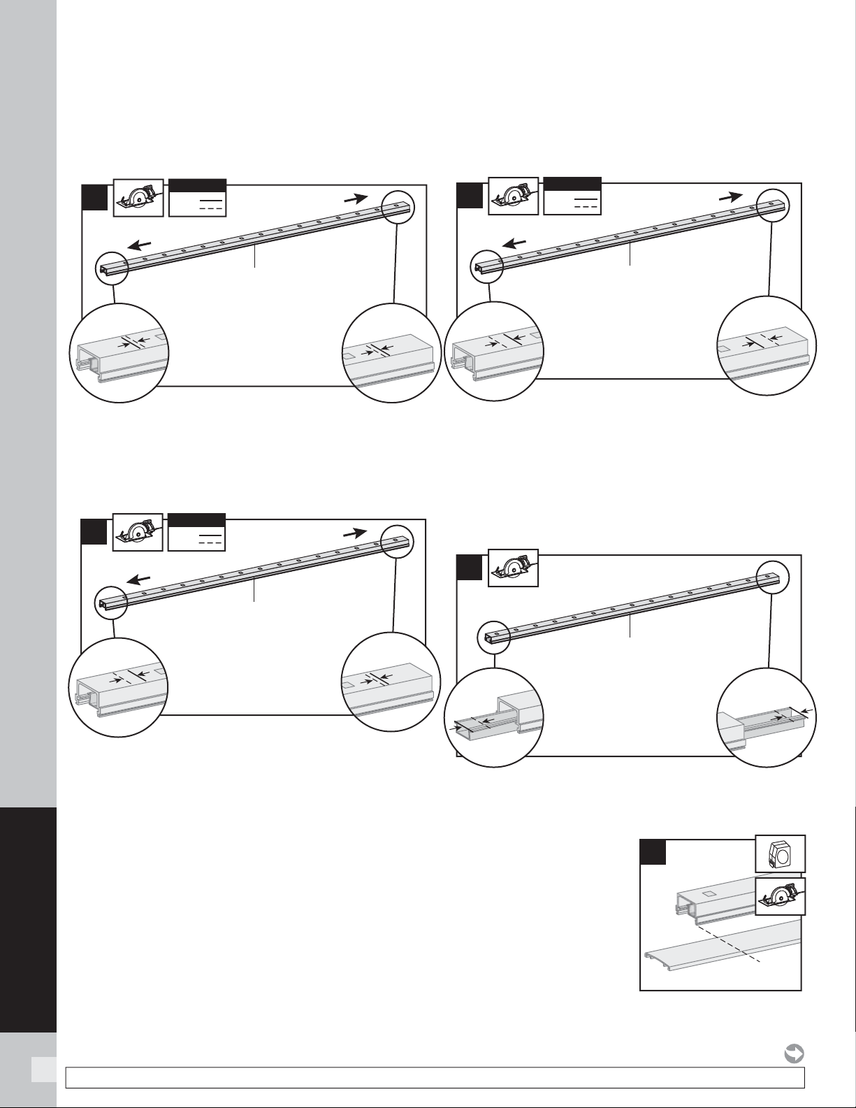
80
SIGNATURE RAILING
NOTE: Construction methods are always improving. Please refer to www.trex.com for the most up-to-date installation requirements.
Cutting Top Rail
Option 1:
For Post-to-Post Configuration
5a. Cut each end of top rail 1/4" (0.6 cm) shorter than
mark to allow for fi t into top rail brackets.
Cutting Top Rail
Option 2:
For Post-to-Crossover-Post Configuration
5b. Top rail must be cut differently on each side of the
rail. Railing side that attaches to standard post
should be cut 1/4" (0.6 cm) shorter than the mark
to allow for fi t into top rail bracket. Railing side that
attaches to the crossover post should be cut
3/4" (1.9 cm) LONGER than the mark to allow for fi t
into the crossover post bracket.
Cutting Top Rail
Option 3:
For Crossover-Post-to-Crossover-Post Confi guration
5c. Cut each end of top rail 3/4" (1.9 cm) LONGER
than the mark to allow for fi t into the crossover post
bracket on each side.
Cutting Top Rail Insert and Cover
6. Slide rail insert out and cut 3/4" (1.9 cm) FROM
EACH SIDE of insert, then slide back inside rail
and center.
7. Mark and cut top rail
cover same length as
top rail for all top rail
confi gurations.
HOW TO INSTALL HORIZONTAL RAILING/CONTINUED
TREX SIGNATURE
STANDARD
7
5a
1/4"
(0.6 cm)
1/4"
(0.6 cm)
1/4"
(0.6 cm)
1/4"
(0.6 cm)
KEY
Mark
Cut
KEY
Top rail
Standard post
Standard post
5c
3/4"
(1.9 cm)
3/4"
(1.9 cm)
3/4"
(1.9 cm)
3/4"
(1.9 cm)
KEY
Mark
Cut
KEY
Top rail
Crossover post
Crossover post
5b
1/4"
(0.6 cm)
1/4"
(0.6 cm)
3/4"
(1.9 cm)
3/4"
(1.9 cm)
KEY
Mark
Cut
KEY
Top rail
Crossover post
Standard post
6
3/4"
(1.9 cm)
3/4"
(1.9 cm)
3/4"
(1.9 cm)
3/4"
(1.9 cm)
Top rail
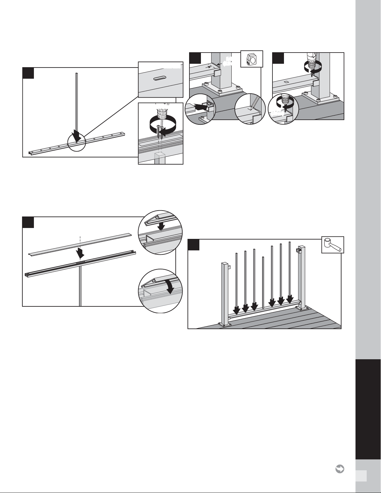
81
SIGNATURE RAILING
Attaching Center Baluster to Bottom Rail
8. Attach shorter, center baluster in center slot in
bottom rail using two #8 x 1-1/4" (3.2 cm) screws
(provided).
Attaching Bottom Rail Cover and
Bottom Rail to Brackets
9. Attach “fl at” bottom rail cover to bottom rail by
fi rst centering cover on bottom rail (this will allow
gap on each end of bottom rail for placement into
brackets). Align cover on one side of bottom rail in
slot on side of rail. Then starting from one end of
rail snap cover onto opposing slot working down the
length of rail. In some cases, a rubber mallet may
facilitate the fastening using GENTLE tapping.
10. Set bottom rail into bottom brackets. Tabs on
brackets will be inside of bottom rail (not shown
when railing is attached). To ensure fi t into tab,
measure and mark 1/2" (1.3 cm) out from side
of post.
11. Attach bottom rail to bottom bracket by fastening
through marked measurement on top of rail into
tab on bottom bracket using one self-tapping screw
each side (provided).
NOTE: Pre-drilling is recommended (7/64" [0.28 cm]
drill bit) for attachment of railing to bracket.
Installing Remaining Balusters into Bottom Rail
12. Place remaining balusters into holes in lower rail by
snapping fully into place. In some cases, a rubber
mallet may facilitate the fastening using GENTLE
tapping.
HOW TO INSTALL HORIZONTAL RAILING/CONTINUED
TREX SIGNATURE
STANDARD
1/2"
(1.3 cm)
1/2"
(1.3 cm)
10
2
1
2
11
1
7/64"
(.28 cm)
7/64"
(.28 cm)
12
1
9
3
2
1
8
Inverted Bottom viewInverted Bottom view
Center balluster slot
Center balluster slot
2
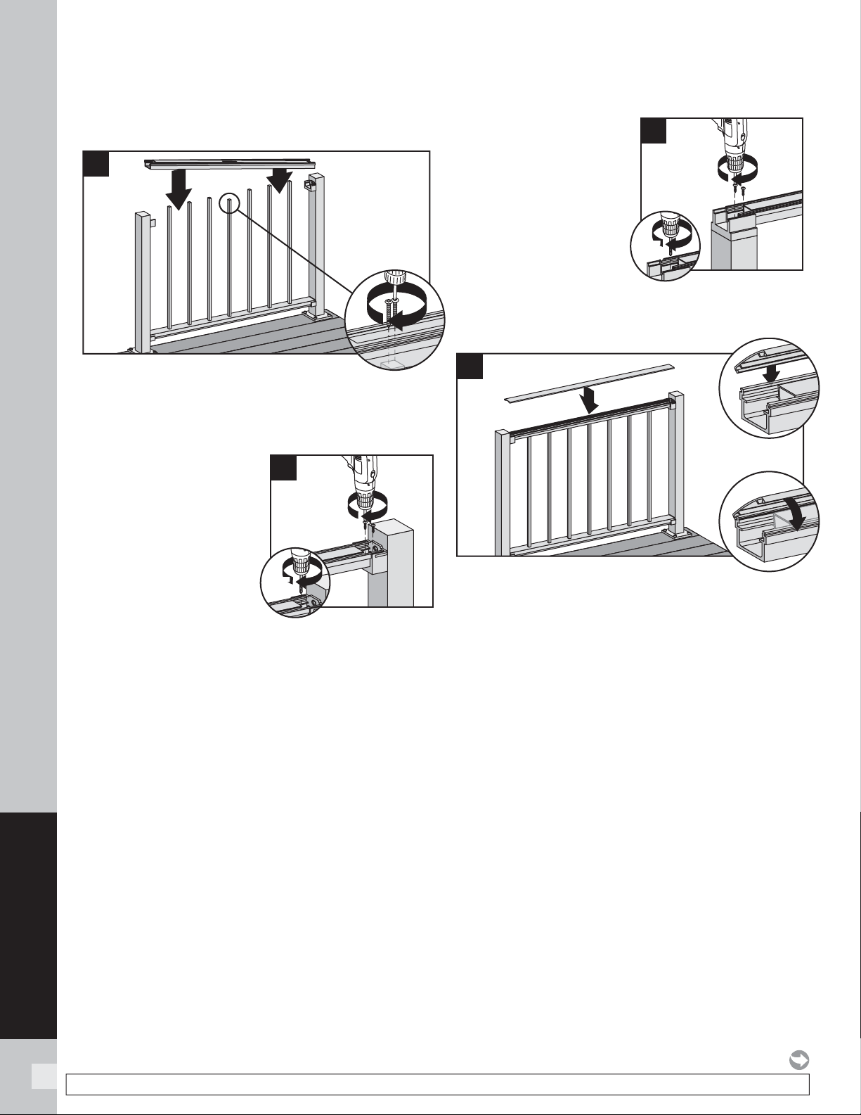
82
SIGNATURE RAILING
NOTE: Construction methods are always improving. Please refer to www.trex.com for the most up-to-date installation requirements.
Attach Upper Railings
13. Working from one end of upper rail, snap balusters
into upper rail working down length of rail. Fasten
center baluster into center slot using two #8 x 1-1/4"
(3.2 cm) screws (provided).
14. For post-to-post
confi guration, fasten
upper rail to each
bracket by installing
screws diagonally
through upper rail into
bracket using two self-
tapping screws each
side (provided).
NOTE: Pre-drilling is recommended (7/64" [0.28 cm]
drill bit) for attachment of railing to bracket.
15. For crossover post
confi guration, fasten
upper rail to crossover
post by installing
screws diagonally
through upper rail
into post using two
self-tapping screws
each side (provided).
NOTE: Pre-drilling is recommended (7/64" [0.28 cm]
drill bit) for attachment of railing to post.
16. Attach “crowned” upper rail cover to upper rail
by aligning cover on one side of rail. Then starting
from one end of rail, snap cover onto opposing slot
working down length of rail. A rubber mallet may
facilitate the fastening using GENTLE tapping.
HOW TO INSTALL HORIZONTAL RAILING/CONTINUED
TREX SIGNATURE
STANDARD
1
16
3
2
2
15
1
7/64"
(.28 cm)
7/64"
(.28 cm)
2
14
1
7/64"
(.28 cm)
7/64"
(.28 cm)
1
1
13
2
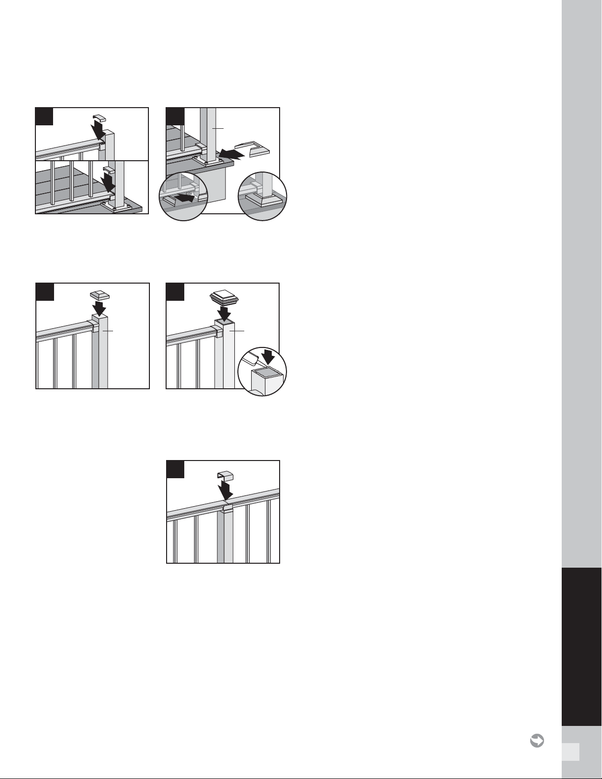
83
SIGNATURE RAILING
HOW TO INSTALL HORIZONTAL RAILING/CONTINUED
TREX SIGNATURE
STANDARD
Attachment of Bracket Covers, Skirts, and Caps
17. Attach corresponding bracket covers over opening in
upper and bottom rails.
18. Attach provided post skirt to bottom of posts when
using Signature posts.
19. Attach post caps to Signature posts. (Use of rubber
mallet may be required for secure attachment.)
20. Attach post caps to post sleeves using external
grade PVC construction adhesive.
21. For crossover post
confi guration, attach
crossover post cap to
crossover post.
1
19
Signature
post
2
Post
sleeve
20
3
1
21
1
18
Signature
post
2
1
2
17
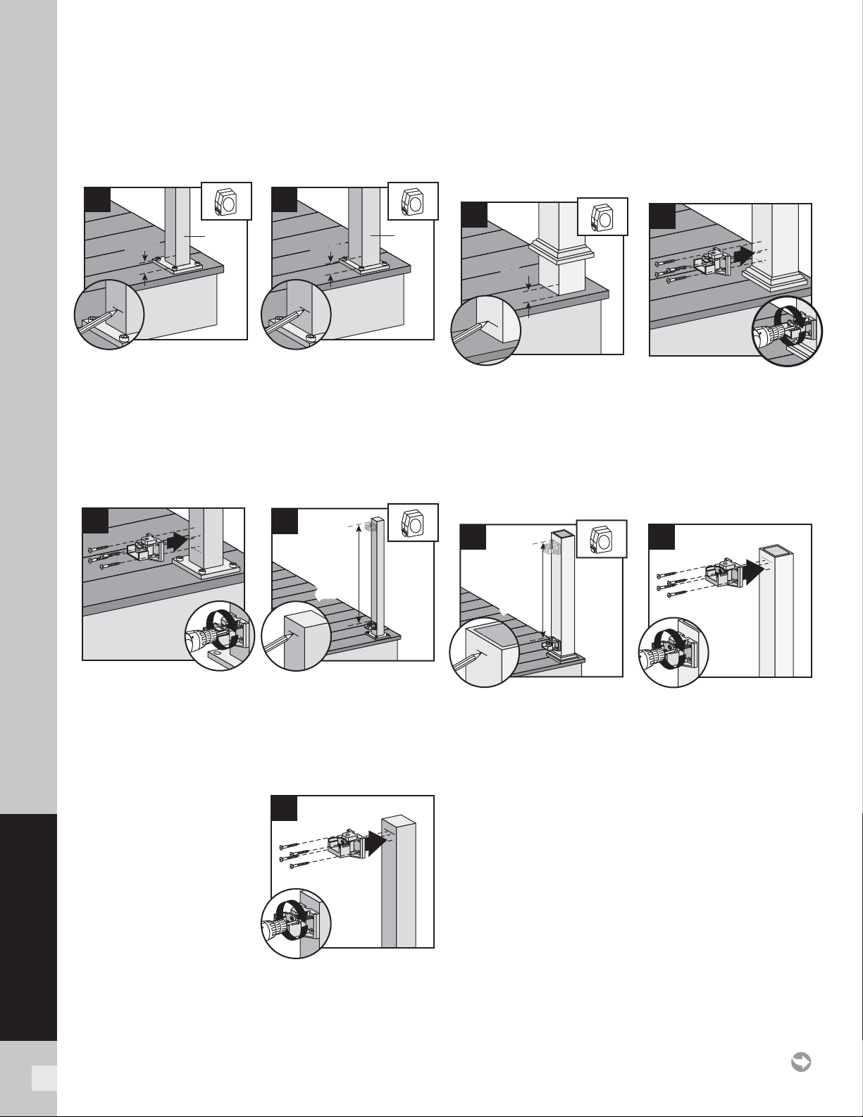
84
SIGNATURE RAILING
Attach Swivel Bracket Base using Signature Posts
TIP: Use a clamp to help hold brackets in place while
fastening with screws.
1a. When using 2" post, for both post-to-post and
post-to-crossover-post confi gurations, measure
1-1/2" (3.8 cm) up from top of post base plate
(or 1-7/8" [4.8 cm] from decking surface). Mark
with light line.
1b. When using 2.5" post, measure 1-3/8" (3.5 cm)
from top of post base plate (or 1-7/8" [4.8 cm] from
decking surface). Mark with light line.
2. Center lower bracket on post above the marked line
and attach using four self-tapping screws (provided).
3. Measure up 32-5/16" (82.0 cm) for 36" (91.4 cm) tall
railing or 38-5/16" (97.3 cm) for 42" (106.7 cm) tall
railing from top of lower rail bracket. Mark with
a light line.
4. Center upper bracket
on post below marked
line and attach using
four self-tapping
screws (provided).
NOTE: Upper bracket is
not required on crossover
post confi guration.
Attach Brackets Using Pressure-treated Posts
and Post Sleeves
TIP: Use a clamp to help hold brackets in place while
fastening with screws.
5. Measure 1-7/8" (4.8 cm) up from deck surface
to bottom of bracket. Slide skirt up to allow for
proper measurement, then push skirt back down
onto surface of decking BEFORE ATTACHING
BRACKET. Mark with light line.
6. Center lower bracket on post above the marked
line and attach using four 2" (5.1 cm) wood screws
(provided).
7. Measure up 32-5/16" (82.0 cm) for 36" (91.4 cm)
tall railing or 38-5/16" (97.3 cm) for 42" (106.7 cm)
tall railing from top of lower rail bracket. Mark with
a light line.
8. Center upper bracket on post below marked line
and attach using four 2" (5.1 cm) wood screws
(provided).
INSTALLATION OF HORIZONTAL SWIVEL BRACKETS
TREX SIGNATURE
STANDARD
1-1/2"
(3.8 cm)
1-1/2"
(3.8 cm)
2" Post2" Post
1a
32-5/16"
(82.0 cm)
or
38-5/16"
(97.3 cm)
32-5/16"
(82.0 cm)
or
38-5/16"
(97.3 cm)
3
1-7/8"
(4.8 cm)
1-7/8"
(4.8 cm)
5
32-5/16"
(82.0 cm)
or
38-5/16"
(97.3 cm)
32-5/16"
(82.0 cm)
or
38-5/16"
(97.3 cm)
7
1-3/8"
(3.5 cm)
1-3/8"
(3.5 cm)
2-1/2"
Post
2-1/2"
Post
1b
1
2
2
1
4
2
1
6
2
1
8
2
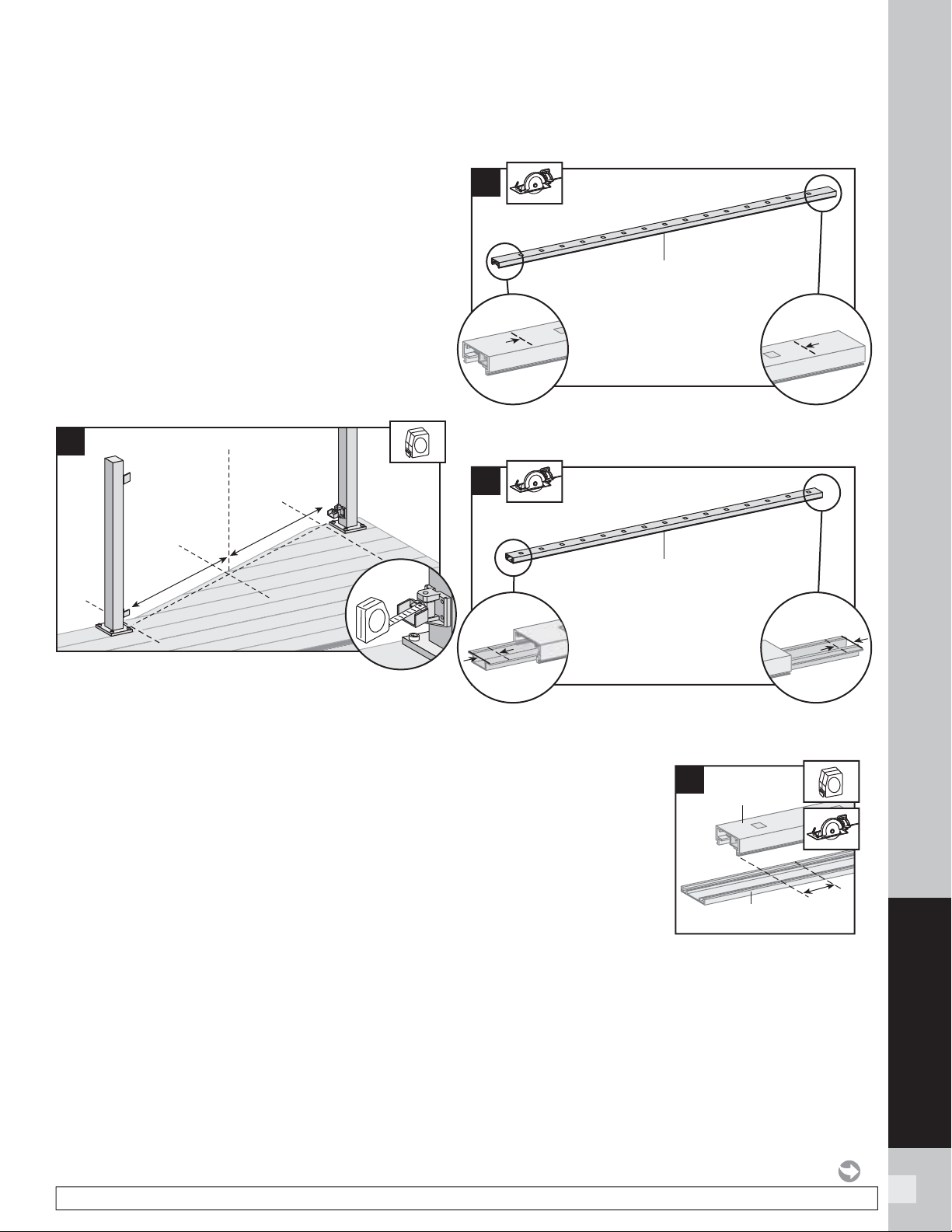
85
SIGNATURE RAILING
NOTE: Construction methods are always improving. Please refer to www.trex.com for the most up-to-date installation requirements.
INSTALLATION OF HORIZONTAL SWIVEL RAILING
TREX SIGNATURE
STANDARD
NOTES:
» WHEN USING SIGNATURE HORIZONTAL SWIVEL BRACKETS BOTH
BOTTOM AND TOP RAILS WILL NEED TO BE MEASURED AND CUT TO
APPROPRIATE LENGTHS.
» HORIZONTAL SWIVEL BRACKETS CAN BE USED UP TO A 50º ANGLE FOR
SIGNATURE RAILINGS.
» WHEN USING HORIZONTAL SWIVEL BRACKETS VERY IMPORTANT
TO LAY OUT LOCATION AND ORIENTATION OF POSTS AND SWIVEL
BRACKETS BEFORE INSTALLING SWIVEL BRACKETS.
» WHEN RAILINGS ARE CUT TO ODD SPANS, ALL SPANS GREATER THAN
5' (1.52 M) (EXAMPLE: 8' (2.44 M) SPAN CUT INTO ONE 5' (1.52 M) SPAN
AND ONE 3' (0.91 M) SPAN) WOULD REQUIRE FOOT BLOCK UNDER
5' (1.52 M) SPAN SINCE SMALLER FIXED BALUSTER IS NO LONGER
CENTERED.
How to Measure and Cut Bottom and Top
Railings
1. With brackets in correct swivel location, measure
distance from inside of bracket to inside of bracket.
ENSURE THAT BEFORE CUTTING, BALUSTERS
HOLES ON BOTH BOTTOM AND TOP RAIL LINE
UP. ALSO MAKE SURE CENTER BALUSTER SLOT
IS AS CLOSE TO THE MIDDLE OF THE SPAN AS
POSSIBLE. In some cases due to odd railing spans,
the center baluster may need to be offset in one or
the other direction to ensure there is enough room at
both post locations for balusters to be placed.
Cutting Bottom Rail and Bottom Rail Cover
2. Cut bottom rail to the measurement between the
bottom swivel brackets.
3. Slide rail insert out and cut 3/4" (1.9 cm) FROM
EACH SIDE of insert, then slide back inside rail
and center.
4. Mark and cut bottom
rail cover 1-1/2"
(3.8 cm) shorter than
bottom rail.
1
Center slot
for fixed
baluster
2
Bottom rail
3
3/4"
(1.9 cm)
3/4"
(1.9 cm)
3/4"
(1.9 cm)
3/4"
(1.9 cm)
Bottom rail
1-1/2"
(3.8 cm)
1-1/2"
(3.8 cm)
4
Bottom rail
Bottom
rail cover
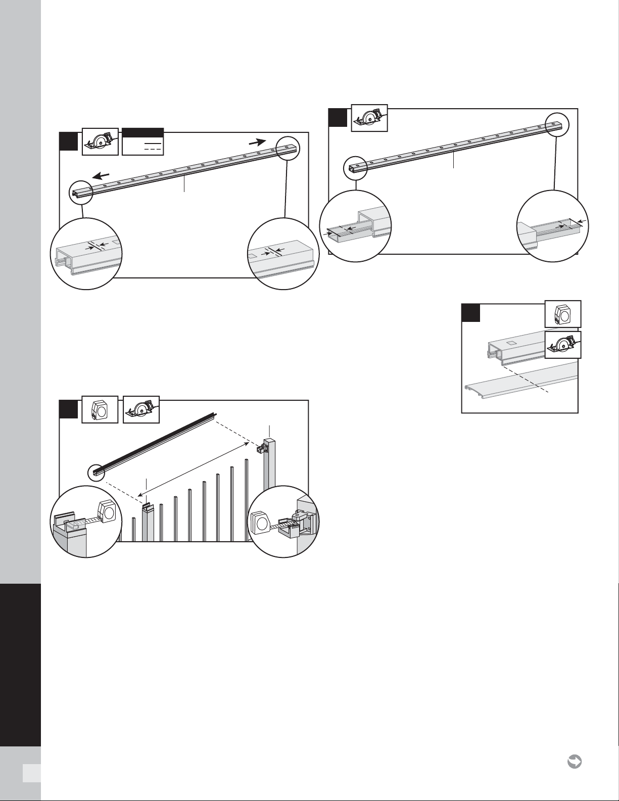
86
SIGNATURE RAILING
INSTALLATION OF HORIZONTAL SWIVEL RAILING/CONTINUED
TREX SIGNATURE
STANDARD
Cutting Top Rail
Option 1:
For Post-to-Post Configuration
5a. Cut top rail to the measurement between the top
swivel brackets. For standard-post-to-standard-
post confi gurations this would be same dimensions
as that of the bottom rail.
Cutting Top Rail
Option 2:
For Post-to-Crossover-Post Configuration
5b. When going from standard-post-to-crossover-post,
measurement must be taken from inside of top
horizontal swivel bracket to inside lip of crossover
bracket (which is attached to top of crossover
post).
Cutting Top Rail Insert and Cover
6. Slide rail insert out and cut 3/4" (1.9 cm) FROM
EACH SIDE of insert, then slide back inside rail
and center.
7. Mark and cut top rail
cover same length as
top rail for all top rail
confi gurations.
8.
Attaching Center
Baluster to Bottom Rail
See instructions on page 81.
9.
Attaching Bottom Rail Cover and Bottom
Rail to Brackets
See instructions on page 81.
10.
Installing Remaining Balusters into
Bottom Rail
See instructions on page 81.
11.
Attach Upper Railings
See instructions on page 82.
12.
Attachment of Bracket Covers, Skirts, and
Caps
See instructions on page 83.
13.
Attachment of Foot Block (Required ONLY for
All Clear Span Applications Over 6
'
[1.83 m])
See instructions on page 89.
5a
1/4"
(0.6 cm)
1/4"
(0.6 cm)
1/4"
(0.6 cm)
1/4"
(0.6 cm)
KEY
Mark
Cut
KEY
Top rail
Standard post
Standard post
5b
Crossover
post
Standard
post
6
3/4"
(1.9 cm)
3/4"
(1.9 cm)
3/4"
(1.9 cm)
3/4"
(1.9 cm)
Top rail
7
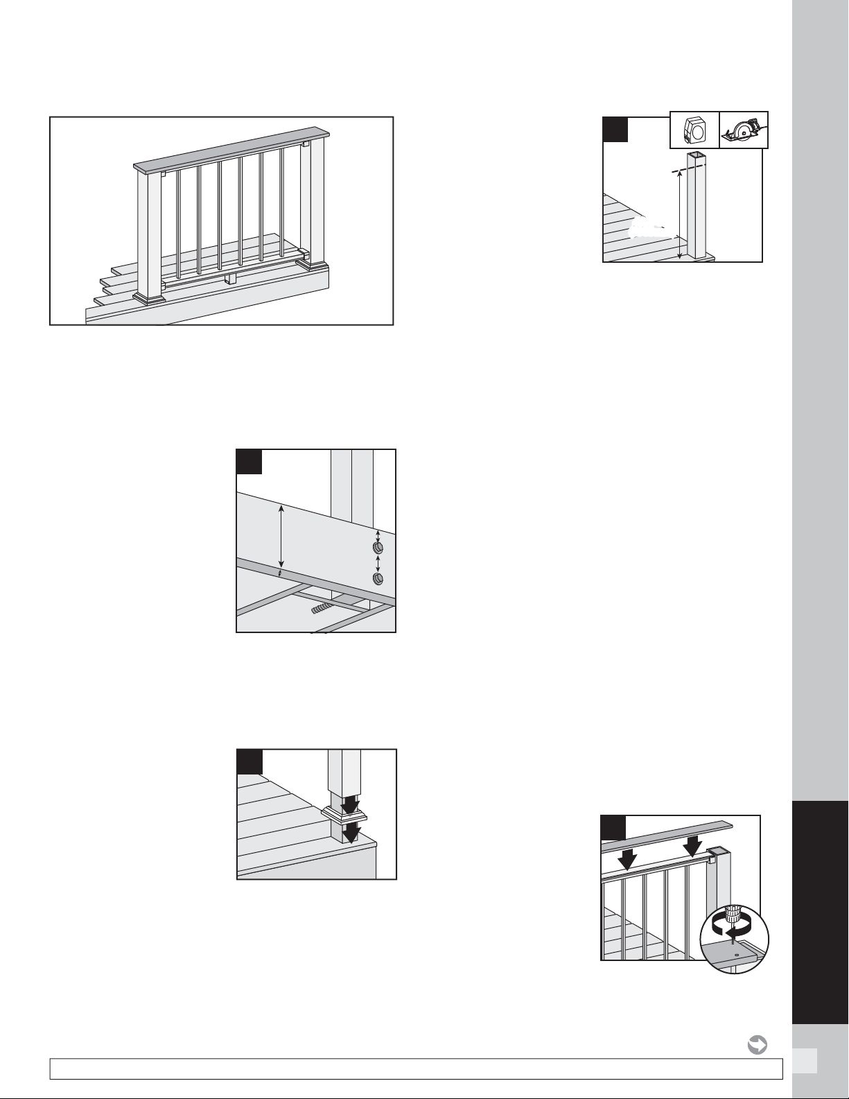
87
SIGNATURE RAILING
NOTE: Construction methods are always improving. Please refer to www.trex.com for the most up-to-date installation requirements.
Important: ONLY for use with pressure-treated 4 x 4
post (3.5" nominal square) and 4" x 4" (102 mm x 102
mm) post sleeve. Trex Signature posts, Trex post mounts
or joist mount posts cannot be used with Signature
Cocktail railing. Cutting post and post sleeve ONLY
apply to the Cocktail style railing.
Installing Pressure-
treated Posts, Post
Sleeves,and Skirts to
Use with Signature
Railing
1a. Attach posts using 1/2"
(13 mm) carriage bolts.
» Minimum joist size is
2" x 8" (51 mm x
203 mm).
» Top bolts must be 1"
(25 mm) from top of
joists.
» Bottom bolts must be 5-1/8" (130 mm) from
top bolts.
NOTE: Blocking can be added for extra strength.
1b. Slide post sleeve skirt over post and down to rest
on decking surface.
Slide post sleeve over
post and position inside
post sleeve skirt.
NOTE: Shims can be used
to plumb post sleeves.
Cutting Post and Post
Sleeve
2. Mark and cut post and
post sleeve measuring
from deck surface:
» 36-1/32" (915 mm)
for 36 " (914 mm)
height.
» 42-1/32" (1068 mm)
for 42 " (1067 mm) height.
3.
Installing Horizontal Fixed Brackets
See instructions on page 78.
4.
Installing Horizontal Swivel Brackets
See instructions on page 84.
5.
Cutting Railings for Horizontal Fixed
Brackets
See instructions on page 79.
6.
Cutting Railings for Horizontal Swivel
Brackets
See instructions on page 85.
7.
Attaching Center Baluster to Bottom Rail
See instructions on page 81.
8.
Attaching Bottom Rail Cover and Bottom
Rail to Brackets
See instructions on page 81.
9.
Installing Remaining Balusters into
Bottom Rail
See instructions on page 81.
10.
Attaching Top Rail and Top Rail Cover
See instructions on page 82. Note: Top Bracket
Covers are not attached in this confi guration.
11.
Attaching Deck Board to Top Rail
Place deck boards
(DO NOT use
Escapes or Contour
deck boards for
top rail) over top
rails. Attach boards
on each post with
Trex-recommended
composite screws
(quantity of 2 per each
board end).
HOW TO INSTALL SIGNATURE COCKTAIL RAILING
TREX SIGNATURE
36-1/32"
(915 mm)
or
42-1/32"
(1068 mm)
36-1/32"
(915 mm)
or
42-1/32"
(1068 mm)
2
1
1
11
2
1
2
1b
1a
5-1/8" (130 mm) min.
2" x 8"
(51 mm x
203 mm)
min.
1" (25 mm) min.
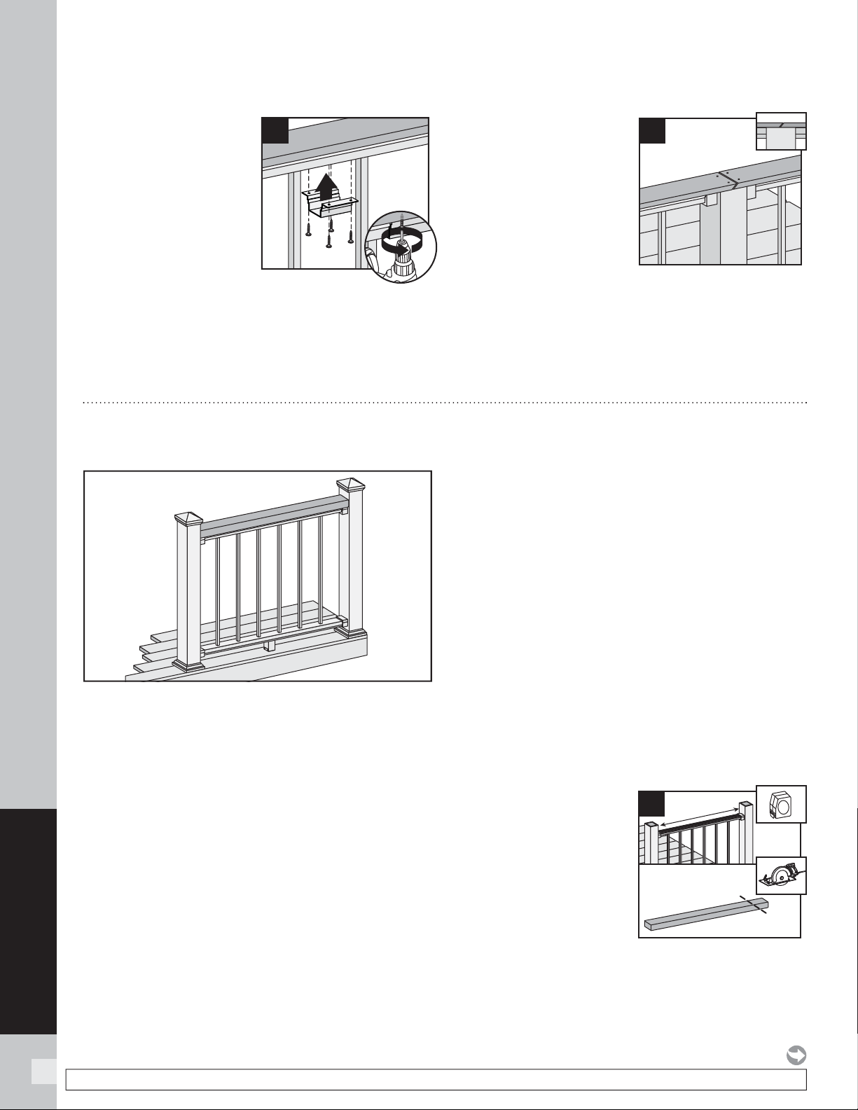
88
SIGNATURE RAILING
NOTE: Construction methods are always improving. Please refer to www.trex.com for the most up-to-date installation requirements.
HOW TO INSTALL SIGNATURE COCKTAIL RAILING/CONTINUED
TREX SIGNATURE
12. Secure boards to top
rail using Signature
Cocktail Bracket
(sold separately).
Ensure that there is a
bracket at each end
of the railing section,
then space brackets
approximately every
24" and attach with
4 screws provided.
NOTE: Predrilling before attachment is recommended.
13. Use scarf cut for
posts where two deck
boards meet.
NOTES:
»
If installing in weather
below 40°F (4.5°C),
leave 1/8" (3 mm) gap
between deck boards.
»
Deck boards can overhang
end of last post
maximum 1/2" (13 mm).
14.
Attachment of Bottom Bracket Covers and
Skirts
See instructions on page 83.
13
1
12
2
Important: ONLY use for use with pressure-treated
4 x 4 post (3.5" nominal square) and 4" x 4" (102 mm x
102 mm) or 6" x 6" post sleeve. Trex Signature Posts,
Trex Post Mounts or Joist Mount Posts cannot be used
with Signature Traditional railing.
1.
Installing Posts, Post Sleeve Skirts and
Post Sleeves
See instructions on page 74.
2.
Installing Horizontal Fixed Brackets
See instructions on page 78.
3.
Installing Horizontal Swivel Brackets
See instructions on page 84.
4.
Cutting Railings for Horizontal Fixed
Brackets
See instructions on page 79.
5.
Cutting Railings for Horizontal Swivel
Brackets
See instructions on page 85.
6.
Attaching Center Baluster to Bottom Rail
See instructions on page 81.
7.
Attaching Bottom Rail Cover and Bottom
Rail to Brackets
See instructions on page 81.
8.
Installing Remaining Balusters into
Bottom Rail
See instructions on page 81.
9.
Attaching Top Rail and Top Rail Cover
See instructions on page 82. Note: Top Bracket
Covers are not attached in this confi guration.
10.
Attaching 2" x 4"
(51 mm x 102 mm)
to Top Rail
Measure between
posts and cut 2" x 4"
(51 mm x 102 mm)
to length.
HOW TO INSTALL SIGNATURE TRADITIONAL RAILING
TREX SIGNATURE
®
10
1
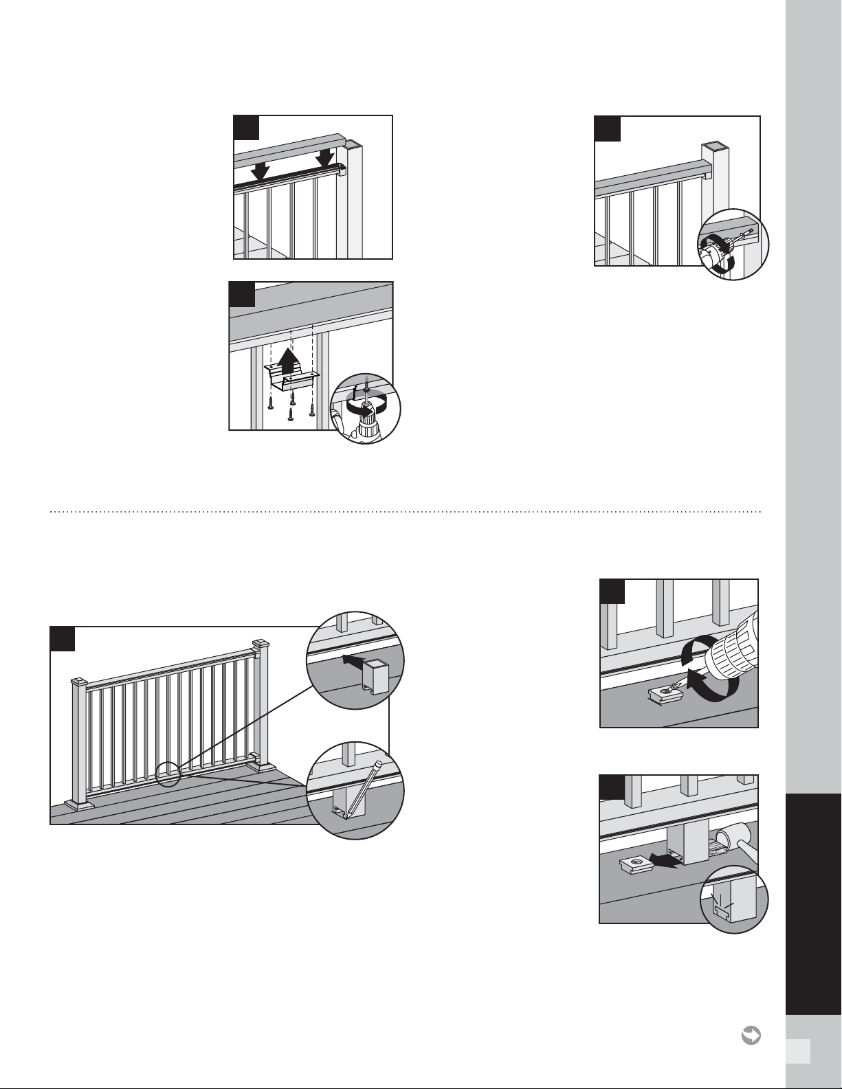
89
SIGNATURE RAILING
11. Place 2" x 4" (51 mm x
102 mm) on Signature
top rail.
12. Secure 2" x 4" (51
mm x 102 mm) to top
rail using Signature
Cocktail Bracket
(sold separately).
Ensure that there is a
bracket at each end
of the railing section,
then space brackets
approximately every
24" and attach with 4 screws provided.
NOTE: Predrilling before attachment is recommended.
13. Pre-drill a pilot hole
and toenail 2-1/2"
(6.4 cm) screw at each
end of 2" x 4" (5.1 cm x
10.2 cm) into post on
back side of rail (side
not facing decking).
14.
Attachment of Bottom Rail Bracket Covers
and Caps
See instructions on page 83.
1
1
11
1
12
2
13
HOW TO INSTALL SIGNATURE TRADITIONAL RAILING/CONTINUED
TREX SIGNATURE
HOW TO INSTALL FOOT BLOCKS–HORIZONTAL RAILING
TREX SIGNATURE
Attachment of Foot Block (Required ONLY for All
Clear Span Applications Over 6
'
[1.83 m] )
1. To ensure correct location, place foot block under
center of bottom rail. Mark to provide placement
location of base.
2. Place base (smaller
side facing down) on
decking surface. Attach
base of foot block using
one screw at an angle
through base and into
decking.
NOTE: Pre-drilling is
recommended (1/8"
[0.32 cm] drill bit) for attachment of base.
3. After attached, use a
rubber mallet along
with scrap piece of
wood to tap foot block
until it locks into place.
1
2
1
2
1
3
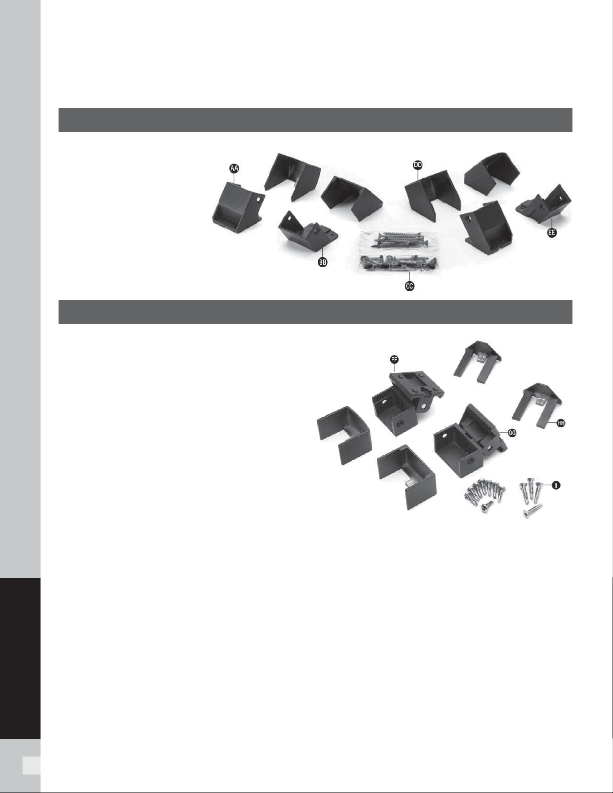
90
SIGNATURE RAILING
BRACKET HARDWARE – STAIR APPLICATIONS
(INCLUDING STAIR SWIVEL BRACKETS, STAIR CROSSOVER BRACKET,
AND COMPOUND SWIVEL BRACKETS)
TREX SIGNATURE
FIXED BRACKET – STAIR HARDWARE
AA. Bottom Stair Bracket and
Cover – Lower Rail
BB. Top Stair Bracket and
Cover – Lower Rail
CC. Fastener Pack
DD. Bottom Stair Bracket and
Cover – Upper Rail
EE. Top Stair Bracket and
Cover – Upper Rail
SWIVEL BRACKET – STAIR HARDWARE
FF. Swivel Top Rail Bracket and Cover – Stair
GG. Swivel Bottom Rail Bracket and Cover – Stair
HH. Fastener Covers
II. Fastener Pack
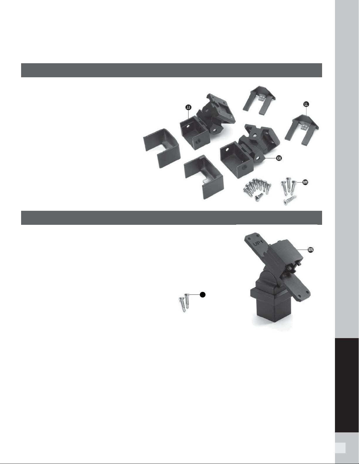
91
SIGNATURE RAILING
BRACKET HARDWARE – STAIR APPLICATIONS
(INCLUDING STAIR SWIVEL BRACKETS, STAIR CROSSOVER BRACKET,
AND COMPOUND SWIVEL BRACKETS)/
CONTINUED
TREX SIGNATURE
COMPOUND SWIVEL BRACKET – STAIR HARDWARE
JJ. Compound Swivel Top Rail Bracket and
Cover – Stair
KK. Compound Swivel Bottom Rail Bracket
and Cover – Stair
LL. Fastener Covers
MM. Fastener Pack
SWIVEL CROSSOVER BRACKET KIT – STAIR HARDWARE
NN. Swivel Crossover Bracket – Stair
OO. Post-to-Bracket Fasteners
OO
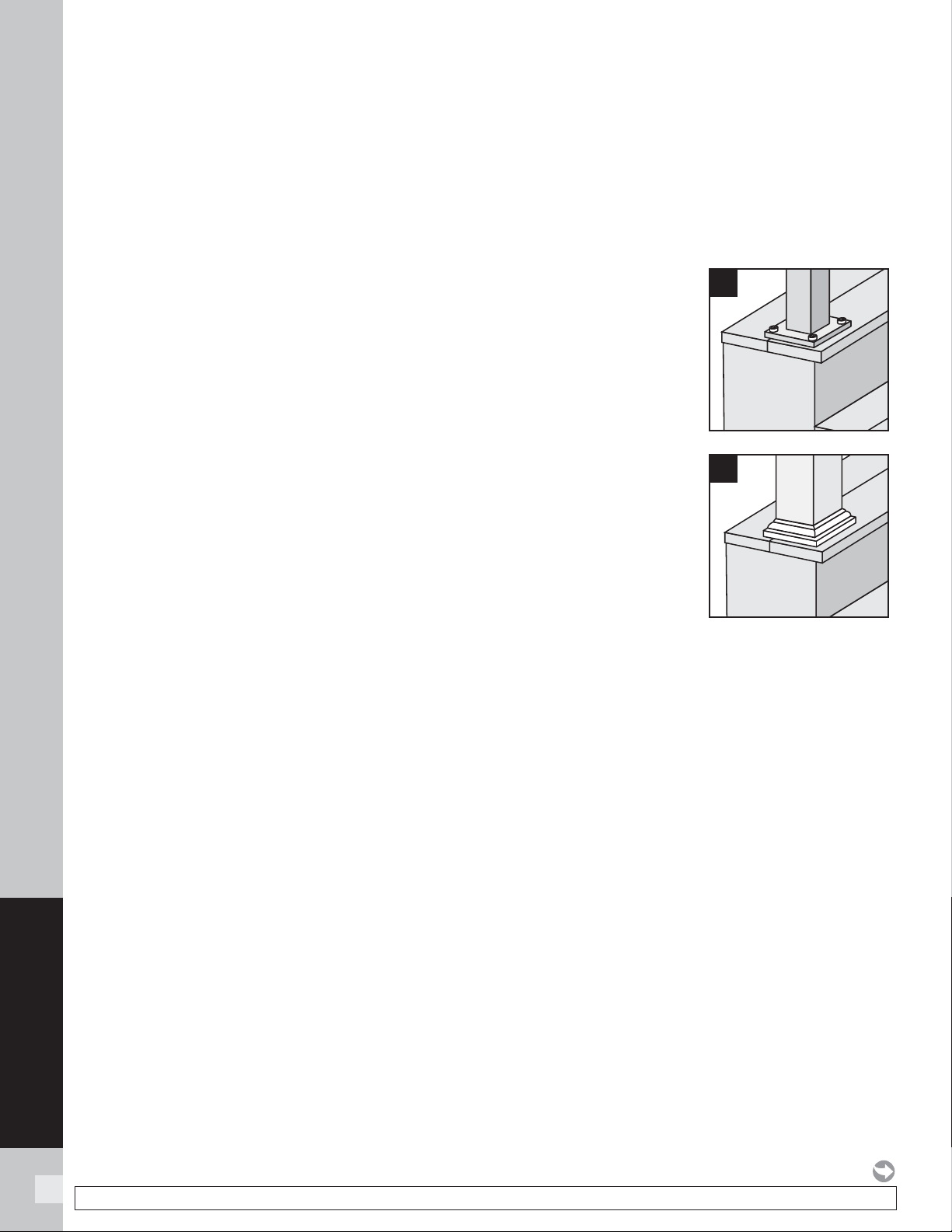
92
SIGNATURE RAILING
IMPORTANT NOTES:
» SIGNATURE POSTS CANNOT BE USED WITH
SIGNATURE TRADITIONAL OR SIGNATURE
COCKTAIL STAIR DESIGNS, ONLY PRESSURE-
TREATED POST/POST SLEEVES CAN BE USED.
REFER TO DETAILED INSTRUCTIONS FOR MORE
INFORMATION.
» ALL SIGNATURE STAIR INSTALLATIONS REQUIRE
THE USE OF 53" (134.6 CM) STAIR POST,
MEASURED AND CUT TO APPROPRIATE LENGTH IF
REQUIRED.
» IF CROSSOVER STAIR POST IS REQUIRED, USE
STAIR POST (AGAIN CUT TO APPROPRIATE LENGTH
IF REQUIRED) AND USE SWIVEL CROSSOVER
BRACKET.
» SIGNATURE STAIR FIXED BRACKETS ARE
DESIGNED TO WORK ONLY WITH STAIR SLOPES OF
32°-37°.
» FOR SMALLER (LESS THAN 32°) OR LARGER
ANGLES (GREATER THAN 37°), USE THE
SIGNATURE STAIR SWIVEL BRACKETS.
» SIGNATURE COMPOUND SWIVEL STAIR BRACKETS
ARE DESIGNED FOR FLARED STAIR DESIGNS.
» IF INSTALLING STAIR RAILINGS AT EXACT SPAN
LENGTHS OF 6' (1.8 M) OR 8' (2.4 M) AND USING
POST TO POST CONFIGURATION, THE BOTTOM
STAIR RAIL WILL NOT NEED TO BE CUT*, BUT THE
TOP STAIR RAIL WILL NEED TO BE MEASURED
(MAKING SURE BALUSTERS LINE UP VERTICALLY)
AND CUT.
» IF INSTALLING STAIR RAILINGS AT EXACT SPAN
LENGTHS OF 6' (1.8 M) OR 8' (2.4 M), AND USING
CROSSOVER POST CONFIGURATION (SPANS FROM
ONE CROSSOVER POST TO ANOTHER CROSSOVER
POST), BOTH THE BOTTOM AND TOP STAIR RAILS
WILL NOT NEED TO BE CUT* IF THE ANGLE IS
APPROXIMATELY 34°.
» AT ALL FINAL END POST CONFIGURATIONS, TOP
STAIR RAIL WILL NEED TO BE MEASURED (MAKING
SURE BALUSTERS LINE UP VERTICALLY) AND CUT.
» FOR ODD SPAN LENGTHS, BOTH BOTTOM AND
TOP STAIR RAILS WILL NEED TO BE MEASURED
(MAKING SURE BALUSTERS LINE UP VERTICALLY)
AND CUT. ALSO ENSURE THAT BALUSTERS ARE
SPACED WITH EQUAL DISTANCE ON EACH SIDE OF
THE POST.
» RAILS THAT DO NOT REQUIRE CUTTING MUST
BE ORIENTED IN THE CORRECT DIRECTION TO
ENSURE BALUSTERS ARE SPACED PROPERLY
WHEN INSTALLED IN BRACKETS. ON BOTH
BOTTOM AND TOP STAIR RAILINGS, BALUSTER
HOLE CLOSEST TO THE END OF THE EACH STAIR
RAIL IS TO BE INSTALLED AT THE TOP OF THE
STAIR SECTION. ENSURE THAT BOTH BOTTOM AND
TOP RAILS ARE CORRECT AND BALUSTERS LINE UP
VERTICALLY BEFORE INSTALLING.
Installing Standard Signature Stair Posts,
Signature Stair Crossover Posts, or Pressure-
treated Post, Post Sleeves and Skirts
1. Make sure 53” (135.6 cm) posts are used for all stair
posts.
2. If Signature stair posts
are used, install at nose
of stair tread directly
under required blocking.
See Signature horizontal
post instructions on
pages 74–75 for details.
3. If pressure-treated post/
post sleeves are used,
posts are to be installed
to the inside of the
last stair stringer (rails
must be over decking
surface). See pressure-
treated post instructions
on pages 74–75 for
details.
2
3
HOW TO INSTALL SIGNATURE STAIR POSTS AND STAIR RAILING
TREX SIGNATURE
NOTE: Construction methods are always improving. Please refer to www.trex.com for the most up-to-date installation requirements.
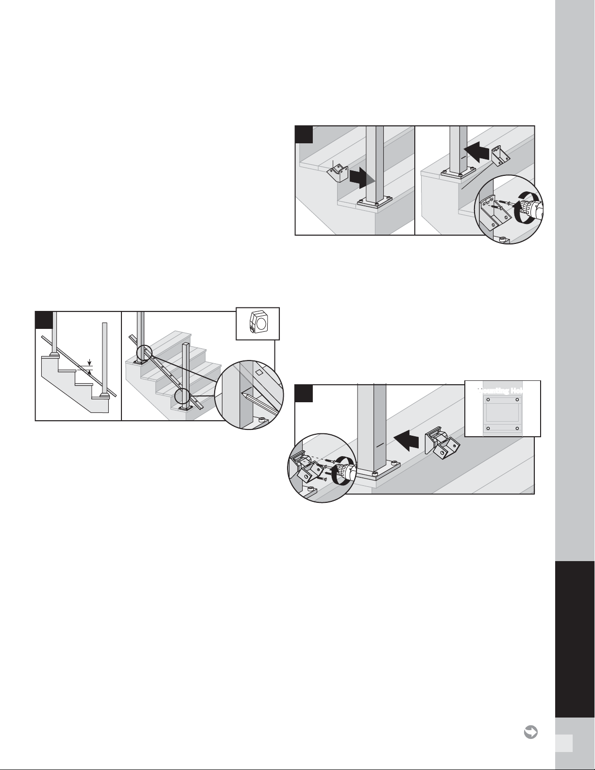
93
SIGNATURE RAILING
ATTACHING STAIR BRACKETS (FIXED STAIR, STAIR SWIVEL, AND
COMPOUND SWIVEL) TO SIGNATURE POSTS AND PRESSURE-
TREATED POST AND POST SLEEVES
TREX SIGNATURE
NOTES:
» All Signature fi xed stair brackets work ONLY with
stair slopes of 32°-37°.
» Illustrations shown are representations when
using Signature post, but same rules apply if using
pressure-treated posts and post sleeves.
» Use a clamp to help hold stair brackets in place
while fastening with screws.
» IMPORTANT NOTE: BEFORE ATTACHING ANY
UPPER BRACKETS MAKE SURE PROPER RAILING
HEIGHTS ARE ACHIEVED. RAILING HEIGHTS AND
UPPER BRACKET HEIGHTS MAY NEED TO BE
ADJUSTED, HOWEVER, DO NOT REDUCE HEIGHTS
BASED ON YOUR RAILING CODE REQUIREMENTS.
MEASURE CAREFULLY as dimension heights may
need to be adjusted!
1. Lay bottom stair rail on steps beside posts. Position
bottom rail at least 1" (2.5 cm) above nose of stair
tread.
TIP: Use a 1" (2.5 cm) deck board as a spacer board
and clamp rails to post. Mark where lower brackets
are to be attached to both posts. Mark at underside of
railing location.
Installing Lower Fixed Stair Brackets
2. Center lower stair bracket on post above the
marked line and attach using two self-tapping
screws (provided). In some cases it may be diffi cult
to attach the stair bracket on the lower stair post.
Recommend using a 90º cordless drill in this area if
possible to attach screws.
Installing Lower Stair Swivel and Compound
Swivel Brackets
NOTE: Picture refl ects lower stair swivel bracket.
3. Center lower stair swivel bracket on post above
the marked line and attach using four self-tapping
screws (provided). In some cases it may be diffi cult
to attach the stair bracket on the lower stair post.
Recommend using a 90º cordless drill in this area if
possible to attach screws.
1"
(2.5 cm)
1
2
Bottom stair
bracket –
bottom rail
Top stair
bracket –
bottom rail
1
1
2
1
3
Mounting HolesMounting Holes
2
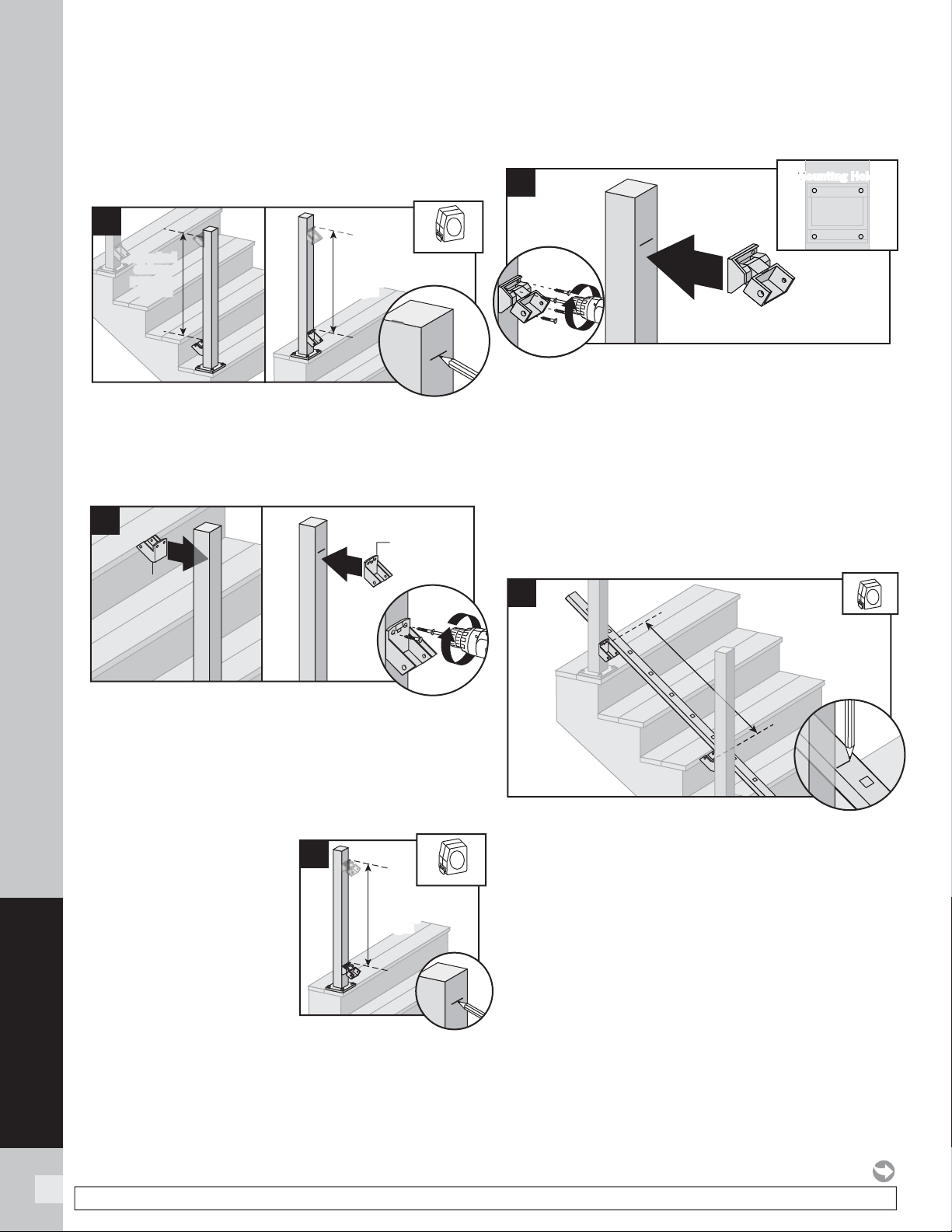
94
SIGNATURE RAILING
ATTACHING STAIR BRACKETS (FIXED STAIR, STAIR SWIVEL, AND
COMPOUND SWIVEL) TO SIGNATURE POSTS AND PRESSURE-
TREATED POST AND POST SLEEVES/
CONTINUED
TREX SIGNATURE
Installing Upper Fixed Stair Brackets
4. Measure up required dimension for
36” (91.4 cm) tall railing or 42” (106.7 cm) tall
railing, from top of lower stair rail fi xed bracket.
Mark with light line.
5. Center upper stair fi xed bracket on post below
the marked line and attach using two self-tapping
screws (provided).
Installing Upper Stair Swivel And Compound
Swivel Brackets
6. Measure up required
dimension for 36” (91.4
cm) tall railing or for 42”
(106.7 cm) tall railing,
from top of lower stair
rail swivel bracket. Mark
with light line.
7. Center upper stair swivel bracket on post below
the marked line and attach using four self-tapping
screws (provided).
NOTE: Upper bracket is not required on crossover
post confi gurations.
How to Measure Bottom Stair Railings
(WHEN REQUIRED)
When Using Fixed Stair Brackets:
1a. Position bottom stair rail along the nose of the stair
treads. Ensure that before cutting, balusters holes
are centered in between the posts and also allow for
clearance for attachment to brackets. Mark bottom
stair rail at each intersection.
Required
distance
per railing
height
Required
distance
per railing
height
Required
distance
per railing
height
Required
distance
per railing
height
4
7
Mounting HolesMounting Holes
2
5
Bottom stair
bracket –
top rail
Top stair
bracket –
top rail
1
1
2
1a
Required
distance
per railing
height
Required
distance
per railing
height
6
NOTE: Construction methods are always improving. Please refer to www.trex.com for the most up-to-date installation requirements.
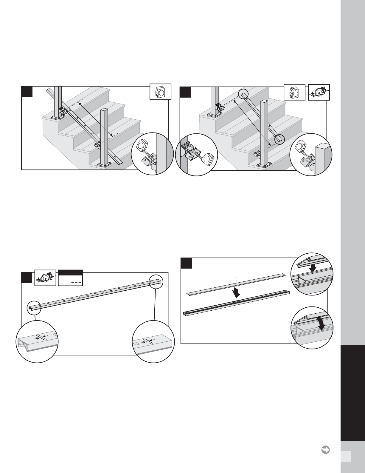
95
SIGNATURE RAILING
When using Stair Swivel and Compound Swivel
Brackets:
1b. With brackets in correct swivel locations, measure
distance from inside of swivel bracket to inside
of swivel bracket. Ensure that before cutting,
balusters holes are parallel and centered in
between the posts and also allow for clearance for
attachment to brackets. Mark bottom stair rail at
each intersection.
Cutting Bottom Stair Rail, Bottom Stair Rail
Cover, and Attachment of Bottom Stair Rail Cover
When using Fixed Stair Brackets:
2a. Cut each end of the bottom stair rail, rail insert, and
bottom rail cover 1/4" (0.6 cm) shorter than the
mark on each end to allow for fi t into bottom stair
rail brackets.
NOTE: Railing does not need to be cut at angle.
Brackets are designed to allow for railing to be
installed with standard straight cut.
When using Stair Swivel or Compound Swivel
Brackets:
2b. Cut each end of the bottom rail, rail insert, and
bottom rail cover at the mark on each end to allow
for fi t into bottom stair rail brackets.
NOTE: Railing does not need to be cut at angle.
Brackets are designed to allow for railing to be
installed with standard straight cut.
Attachment of Bottom Stair Rail Cover and
Bottom Stair Rail to Brackets
3. Attach “fl at” bottom stair rail cover to bottom stair
rail. Align cover on one side of the bottom rail in slot
on side of rail. Then starting from one end of rail
snap cover onto opposing slot working down the
length of the rail. In some cases, a rubber mallet
may facilitate the fastening using GENTLE tapping.
ATTACHING STAIR BRACKETS (FIXED STAIR, STAIR SWIVEL, AND
COMPOUND SWIVEL) TO SIGNATURE POSTS AND PRESSURE-
TREATED POST AND POST SLEEVES/
CONTINUED
TREX SIGNATURE
2a
1/4"
(0.6 cm)
1/4"
(0.6 cm)
1/4"
(0.6 cm)
1/4"
(0.6 cm)
KEY
Mark
Cut
KEY
Bottom stair rail
1b
2b
1
3
3
2
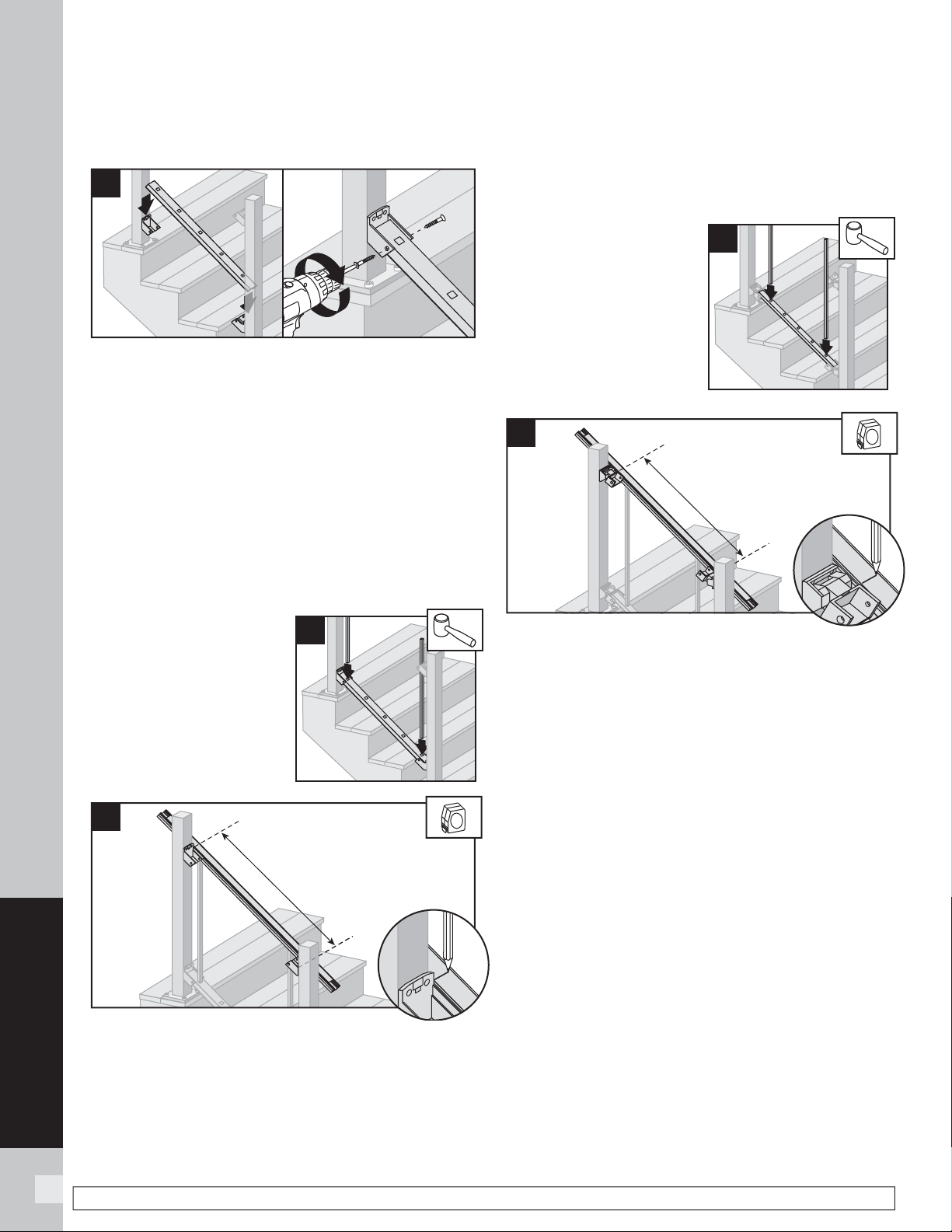
96
SIGNATURE RAILING
96
NOTE: Construction methods are always improving. Please refer to www.trex.com for the most up-to-date installation requirements.
ATTACHING STAIR BRACKETS (FIXED STAIR, STAIR SWIVEL, AND
COMPOUND SWIVEL) TO SIGNATURE POSTS AND PRESSURE-
TREATED POST AND POST SLEEVES/
CONTINUED
TREX SIGNATURE
4. Set bottom stair rail into bottom stair rail brackets.
Attach bottom stair rail to bottom stair bracket
using two self-tapping screws (provided) on each
side of bracket.
How to Measure Top Stair Railings
(WHEN REQUIRED):
IMPORTANT NOTE: BEFORE CUTTING ANY TOP
RAILS MAKE SURE THAT WHEN MEASURING ALL
BALUSTER HOLES LINE UP PARALLEL!
When Using Fixed Stair Brackets:
5a. Place two balusters
into lower rail at each
end closest to post.
5b. Position top rail onto balusters (position to side of
post) and ENSURE that balusters are parallel with
post. Mark top stair rail at each intersection.
When using Stair Swivel and Compound Swivel
Brackets:
5c. Place two balusters into
lower rail at each end
closest to post.
5d. Position top rail onto balusters (position to side
of post) and ENSURE that balusters are parallel
with post. With brackets in correct swivel location,
measure distance from inside of swivel bracket to
inside of swivel bracket. Mark top stair rail at each
intersection.
1
1
4
2
5a
5c
5b
5d
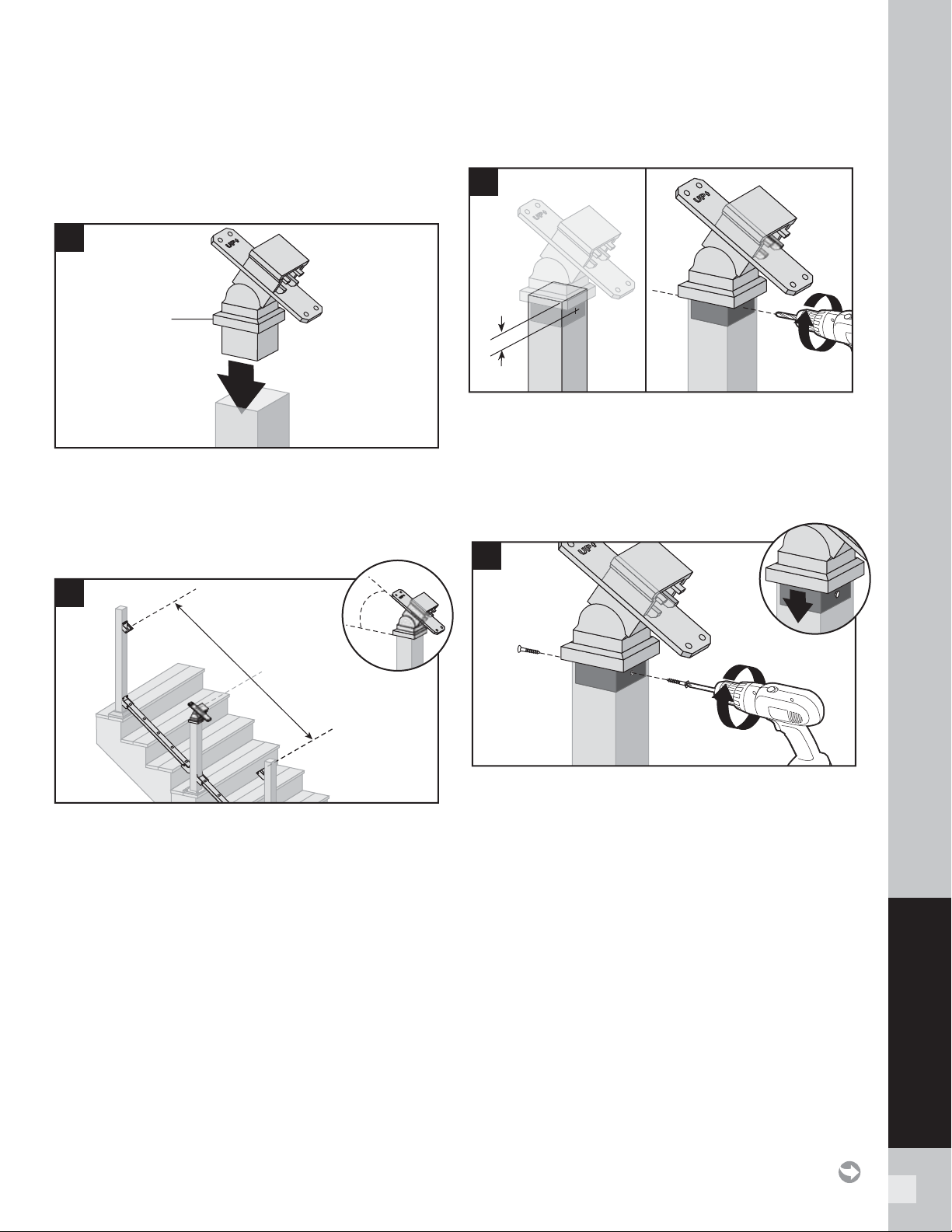
97
SIGNATURE RAILING
Attaching Stair Crossover Swivel Bracket to
Post
6. Insert stair crossover swivel bracket into post.
NOTE: Keep the bracket cover on when inserting this
into post, this will cover the screw attachment area.
7. Determine location/height of the stair crossover
swivel bracket by aligning the angle of this with the
fi xed brackets (or compound swivel brackets) already
installed.
8. Once location/height is determined, center and pre-
drill two holes (using a drill bit slightly smaller than
that of self-tapping screw diameter) on opposite sides
of post, approx. 1/4" from top of post. Drill through
the post and into the stair crossover swivel bracket on
each side.
9. Attach stair crossover swivel bracket to post with two
self-tapping screws (provided). Slide cover over post
to hide screws.
ATTACHING STAIR BRACKETS (FIXED STAIR, STAIR SWIVEL, AND
COMPOUND SWIVEL) TO SIGNATURE POSTS AND PRESSURE-
TREATED POST AND POST SLEEVES/
CONTINUED
TREX SIGNATURE
Bracket
cover
6
7
X°
8
1/4"
(0.6 cm)
1/4"
(0.6 cm)
9
1
2
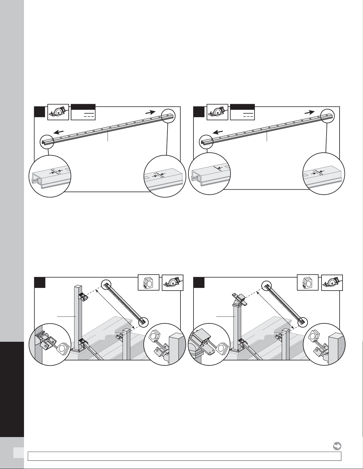
98
SIGNATURE RAILING
98
NOTE: Construction methods are always improving. Please refer to www.trex.com for the most up-to-date installation requirements.
ATTACHING STAIR BRACKETS (FIXED STAIR, STAIR SWIVEL, AND
COMPOUND SWIVEL) TO SIGNATURE POSTS AND PRESSURE-
TREATED POST AND POST SLEEVES/
CONTINUED
TREX SIGNATURE
Cutting Top Stair Rail and Rail Insert
Option 1:
For Stair-Post-to-Stair-Post Configuration
When Using Fixed Stair Brackets:
10a. Cut each end of top stair rail along with rail insert
1/4" (0.6 cm) shorter than mark to allow for fi t into
top stair rail bracket.
NOTE: Railing does not need to be cut at angle.
Brackets are designed to allow for railing to be
installed with standard straight cut.
When using Upper Stair Swivel and Compound
Swivel Brackets:
10b. Cut top rail along with rail insert to the
measurement between the top stair swivel
brackets. For standard post to standard post
confi gurations this would be same dimensions as
that of the bottom stair rail.
Cutting Top Stair Rail and Insert
Option 2:
For Stair-Post-to-Stair-Crossover-Post Configuration
When Using Fixed Stair Brackets:
11a. Top stair rail along with rail insert must be cut
differently on each side of the rail. Railing side
that attaches to standard post should be cut 1/4"
(0.6 cm) shorter than the mark to allow for fi t into
top rail bracket. Railing side that attaches to the
crossover post should be cut directly on the mark
to allow for fi t into the crossover post bracket.
When using Upper Stair Swivel and Stair Crossover
Swivel Brackets:
11b. When going from standard stair post to stair
crossover post, measurement must be taken
from inside of top horizontal stair swivel bracket
to inside lip of stair crossover bracket (crossover
post will need to be modifi ed to have swivel
crossover bracket installed).
11a
1/4"
(0.6 cm)
1/4"
(0.6 cm)
KEY
Mark
Cut
KEY
Top stair rail
Crossover post
Standard post
11b
Crossover
post
Standard
post
Standard
post
10b
Standard
post
Standard
post
Standard
post
10a
1/4"
(0.6 cm)
1/4"
(0.6 cm)
1/4"
(0.6 cm)
1/4"
(0.6 cm)
KEY
Mark
Cut
KEY
Top stair rail
Standard post
Standard post
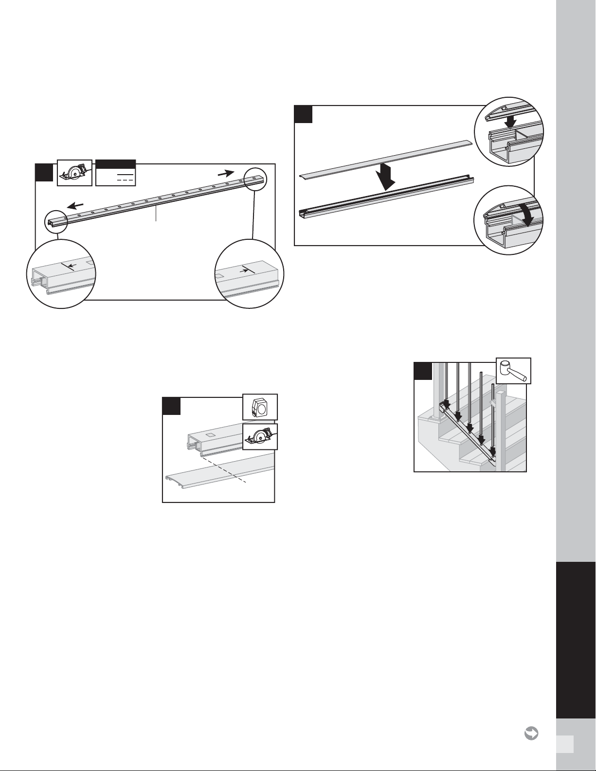
99
SIGNATURE RAILING
ATTACHING STAIR BRACKETS (FIXED STAIR, STAIR SWIVEL, AND
COMPOUND SWIVEL) TO SIGNATURE POSTS AND PRESSURE-
TREATED POST AND POST SLEEVES/
CONTINUED
TREX SIGNATURE
Cutting Top Stair Rail and Rail Insert
Option 3:
For Stair-Crossover-Post-to-Stair-Crossover-Post
Configuration
12a. Cut each end of the top stair rail along with rail
insert on the mark line to allow for fi t into the
crossover post bracket on each side.
Cutting Top Stair Rail Cover, and Attachment of
Top Stair Rail Cover
13. Mark and cut top rail
cover same length as
top rail for all top rail
confi gurations.
14. Attach “crowned” upper stair rail cover to upper
stair rail by aligning cover on one side of rail. Then
starting from one end of stair rail, snap cover onto
opposing slot working down length of stair rail. A
rubber mallet may facilitate the fastening using
GENTLE tapping.
Installing Balusters into Bottom Stair Rail
15. Place balusters into
holes in lower stair rail
by snapping fully into
place. In some cases,
a rubber mallet may
facilitate the fastening
using GENTLE
tapping.
1
14
3
2
15
13
12a
KEY
Mark
Cut
KEY
Top stair rail
Crossover post
Crossover post
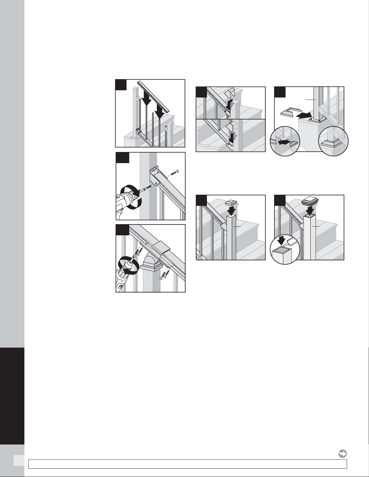
100
SIGNATURE RAILING
100
NOTE: Construction methods are always improving. Please refer to www.trex.com for the most up-to-date installation requirements.
ATTACHING STAIR BRACKETS (FIXED STAIR, STAIR SWIVEL, AND
COMPOUND SWIVEL) TO SIGNATURE POSTS AND PRESSURE-
TREATED POST AND POST SLEEVES/
CONTINUED
TREX SIGNATURE
Attaching Upper Stair Rails
16. Working from one end
of upper stair rail, snap
balusters into upper
stair rail working down
length of rail.
17a. For stair post to post
confi guration, attach
top stair rail to top
stair bracket (all types)
using two self-tapping
screws (provided)
on each side of stair
bracket.
17b. For stair crossover
post confi guration,
fasten upper stair rail
to swivel crossover
post bracket by
installing screws
diagonally through
crossover stair
bracket into upper rail
using two self-tapping
screws (provided) on each side.
NOTE: Pre-drilling is recommended (7/64”
[0.28 cm] drill bit) for attachment of stair railing
to stair bracket.
Attachment of Stair Bracket Covers, Skirts,
and Caps
18. Attach corresponding bracket covers over opening
in upper and bottom rails.
19. Attach provided post skirt to bottom of posts when
using Signature posts.
20. Attach post caps to Signature posts (use of rubber
mallet may be required for secure attachment).
21. Attach post caps to post sleeves using external
grade PVC construction adhesive.
20
Reveal
post
2
21
Post
sleeve
3
1
17a
17b
1
2
18
1
19
Reveal
post
2
16
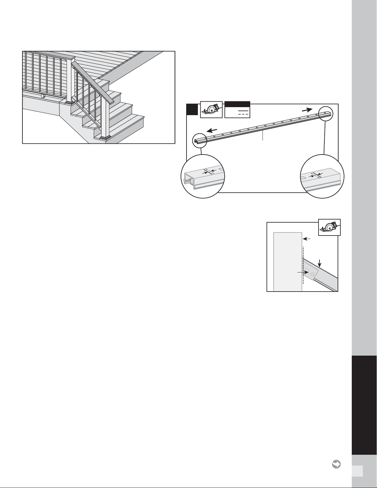
101
SIGNATURE RAILING
IMPORTANT NOTES:
» Only for use with pressure-treated 4 x 4 post
(3.5" nominal square) and 4" x 4" (102 mm x 102
mm) post sleeve. Trex Signature posts, Trex post
mounts or joist mount posts cannot be used with
Signature Cocktail stair railing. Cutting post and
post sleeve only apply to the Cocktail style railing.
» DO NOT CUT POST/POST SLEEVES UNTIL TOP
RAILING AND COVER IS FULLY INSTALLED.
» When referring to previous instructions referenced
disregard all crossover post instructions as these
cannot be used with Cocktail railing.
» THE DECK BOARD USED IN SIGNATURE COCKTAIL
WILL NEED TO TERMINATE AT THE TOP OF THE
POST AS SHOWN ABOVE. THE DECK BOARD WILL
HAVE TO BE TOENAILED INTO THE SIDE OF THE
POST IN THESE AREAS USING 2 APPROPRIATE
COMPOSITE DECKING SCREWS – PREDRILLING
IS RECOMMENDED.
Installing Pressure-treated Posts, Post
Sleeves,and Skirts to Use with Signature Railing
1. See instructions on page 74.
Installing Brackets
2. Follow previous stair instructions for the installation
of desired brackets making sure that all dimensions
are calculated before installation to ensure deck
board is placed in correct location.
See instructions on pages 93–94.
Cutting Bottom Stair Rail, Bottom Stair Rail
Cover and Attachment of Bottom Stair Rail Cover
3. See instructions on page 95.
How to Measure Top Stair Railings
(WHEN REQUIRED)
4. See instructions on page 96.
Cutting Top Stair Rail and Rail Insert When
using Fixed Stair Brackets
5a Cut each end of top stair rail along with rail insert
1/4" (0.6 cm) shorter than mark to allow for fi t into
top stair rail bracket.
NOTE THAT THE TOP
RAIL WILL NEED TO BE
CUT AT APPROPRIATE
ANGLE ON THE END
OF THE RAIL THAT
CONNECTS TO THE
UPPER FIXED BRACKET
SO THAT WHEN THE
RAIL IS INSTALLED IT
SITS FLUSH WITH THE
END OF THE BRACKET AS SHOWN.
Cutting Top Stair Rail and Rail Insert When
using Upper Stair Swivel and Compound Swivel
Brackets
5b. See instructions on page 98.
Cutting Top Stair Rail Cover, and Attachment of
Top Stair Rail Cover
6. See instructions on page 99.
Installing Balusters into Bottom Stair Rail
7. See instructions on page 99.
Attaching Upper Stair Rails
8. See instructions on page 100.
HOW TO INSTALL SIGNATURE COCKTAIL STAIR RAILING
TREX SIGNATURE
5a
1/4"
(0.6 cm)
1/4"
(0.6 cm)
1/4"
(0.6 cm)
1/4"
(0.6 cm)
KEY
Mark
Cut
KEY
Top stair rail
Standard post
Standard post
Post
Top stair rail
Upper
bracket
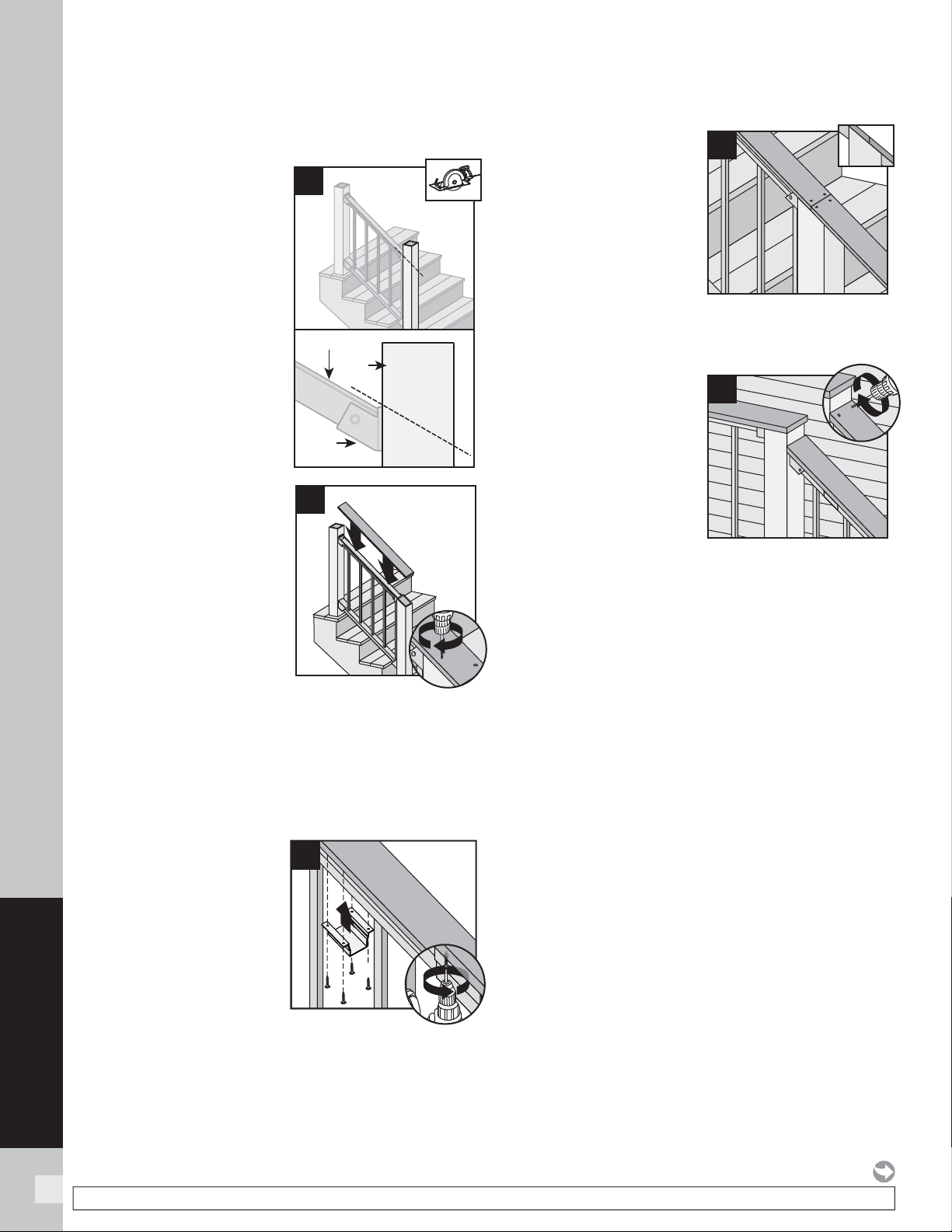
102
SIGNATURE RAILING
NOTE: Construction methods are always improving. Please refer to www.trex.com for the most up-to-date installation requirements.
HOW TO INSTALL SIGNATURE COCKTAIL STAIR RAILING
TREX SIGNATURE/CONTINUED
Cutting Post and Post Sleeve and Attaching
Deck Board to Top Rail
9. Cut post and post
sleeves at proper angle
so these are fl ush
with the top of the top
brackets and/or top rail
cover. BE CAREFUL to
not CUT brackets.
10. Place deck boards
(DO NOT use Escapes
or Contour deck
boards for top rail)
over top rails. PLACE
DECK BOARD ON
TOP RAIL TO CHECK
FOR PROPER FIT AND
RAIL CLEARANCE
FIRST AT BRACKET
LOCATIONS. DECK
BOARD MAY REQUIRE EITHER A NOTCH CUT ON
THE UNDERSIDE OR SLIGHT PLANING ON THE
UNDERSIDE TO ALLOW DECK BOARD TO CLEAR
TOPS OF BRACKETS AND SIT FLUSH ON TOP
OF POSTS AND RAILS. Attach boards on each
post with Trex-recommended composite screws
(quantity of 2 per each board end).
11. Secure boards to top
rail using Signature
Cocktail Bracket (sold
separately). Ensure
that there is a bracket
at each end of the
stair railing section,
then space brackets
approximately every 24"
and attach with
4 screws provided.
NOTE: Predrilling before attachment is recommended.
12. Use scarf cut for
posts where two deck
boards meet.
NOTES:
»
If installing in weather
below 40°F (4.5°C),
leave 1/8" (3 mm) gap
between deck boards.
»
Deck boards can overhang
end of last post
maximum 1/2" (13 mm).
13. Where deck board
terminates at top of
post horizontal deck
board, PREDRILL and
toenail two approved
composite deck
screws as shown into
post, being careful
to avoid hitting stair
bracket.
Attachment of Bracket Covers and Skirts
14. See instructions on page 100.
NOTE: Top Bracket Covers are not attached in this
confi guration.
9
Post
Top stair rail
Upper
bracket
1
1
10
2
12
1
11
2
13
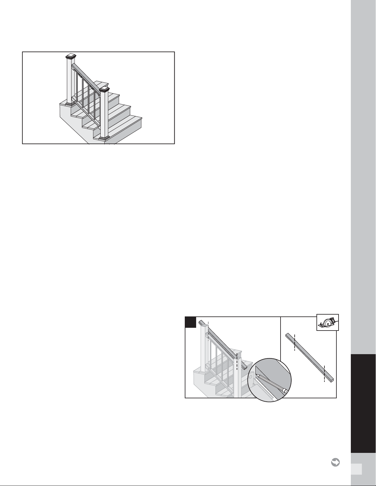
103
SIGNATURE RAILING
Important: ONLY use for use with pressure-treated
4 x 4 post (3.5" nominal square) and 4" x 4" (102 mm x
102 mm) or 6" x 6" post sleeve. Trex Signature Posts,
Trex Post Mounts or Joist Mount Posts cannot be used
with Signature Traditional railing.
Installing Standard Signature Stair Posts, or
Pressure-treated Post
1. See instructions on page 92.
Attaching Stair Brackets
2. See instructions on page 93.
Installing Lower Fixed Stair Brackets
3. See instructions on page 93.
Installing Lower Stair Swivel and Compound
Swivel Brackets
4. See instructions on page 93.
Installing Upper Fixed Stair Brackets
5. See instructions on page 94.
Installing Upper Stair Swivel And Compound
Swivel Brackets
6. See instructions on page 94.
How to Measure Bottom Stair Railings When
Using Fixed Stair Brackets
7. See instructions on page 94.
How to Measure Bottom Stair Railings
When using Stair Swivel and Compound
Swivel Brackets
8. See instructions on page 95.
Cutting Bottom Stair Rail, Bottom Stair Rail Cover
9. See instructions on page 95.
Attachment of Bottom Stair Rail Cover and
Bottom Stair Rail to Brackets
10. See instructions on page 95.
How to Measure Top Stair Railings When
Using Fixed Stair Brackets
11. See instructions on page 96.
How to Measure Top Stair Railings When
using Stair Swivel and Compound Swivel
Brackets
12. See instructions on page 96.
Cutting Top Stair Rail and Rail Insert When
Using Fixed Stair Brackets
13. See instructions on page 98.
Cutting Top Stair Rail and Rail Insert When
using Upper Stair Swivel and Compound
Swivel Brackets
14. See instructions on page 98.
Attachment of Top Stair Rail Cover
15. See instructions on page 98.
Installing Balusters into Bottom Stair Rail
16. See instructions on page 99.
Attaching Upper Stair Rails
17. See instructions on page 100.
Attaching 2” x 4” to Top Rail
18. Place 2" x 4" (51 mm x 102 mm) beside top rail.
Mark and cut (both ends need to be cut on an angle
for proper fi t).
HOW TO INSTALL SIGNATURE TRADITIONAL STAIR RAILING
TREX SIGNATURE
18
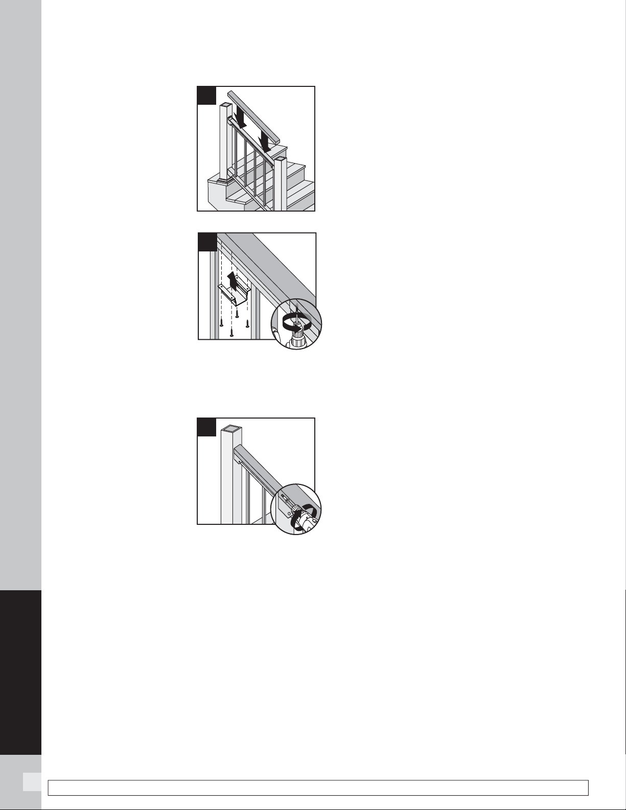
104
SIGNATURE RAILING
NOTE: Construction methods are always improving. Please refer to www.trex.com for the most up-to-date installation requirements.
19. Place 2" x 4" (51 mm x
102 mm) on Signature
top stair rail.
20. Secure 2" x 4" (51
mm x 102 mm) to top
rail using Signature
Cocktail Bracket (sold
separately). Ensure
that there is a bracket at
each end of the railing
section, then space
brackets approximately
every 24" and attach
with 4 screws provided.
NOTE: Predrilling before
attachment is recommended.
21. Pre-drill a pilot hole and
toenail 2-1/2" (6.4 cm)
screw at each end of 2" x
4" (5.1 cm x 10.2 cm) into
post on back side of rail
(side not facing decking).
Attachment of Lower
Stair Bracket Covers,
Skirts, and Caps
22. See instructions on page 100.
NOTE: Top Bracket Covers are not attached in this
confi guration.
HOW TO INSTALL SIGNATURE TRADITIONAL STAIR RAILING/CONTINUED
TREX SIGNATURE
19
1
20
2
21
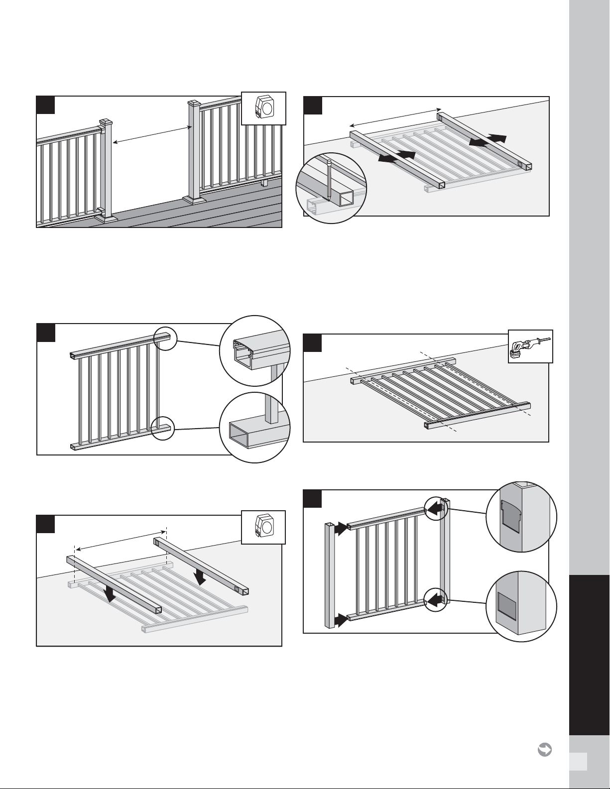
105
SIGNATURE RAILING
INSTALLING ALUMINUM GATE
» SEE PAGE 56 FOR SKU NUMBERS
1. Measure opening between posts (gates can be
customized to fi t nearly any opening up to 48"
[1219 mm] wide).
2. Subtract 1-7/8" (48 mm) from above measurement.
This will allow for proper gapping and location
of gate.
3. Identify top and bottom of panel.
NOTE: The posts only fi t in one direction.
4. Lay panel on a fl at non-marring surface. Place
posts on top of panel. Place posts so that width
measurement from Step 2 is to the outside of each
post.
5. Adjust posts so that cut marks do not fall on a
baluster. Make sure distance from fi rst baluster to
post is the same on both sides. Mark cut locations
on panel.
NOTE: If widths do fall on a baluster, cut baluster
fl ush at top and bottom prior to cutting panel.
6. Cut panel using a reciprocating saw (equipped with
a metal blade).
7. Insert posts into panel.
NOTE: Make sure top and bottom of panel
orientation is correct.
1
3
1
1
1
1
1
5
2
4
1
6
7
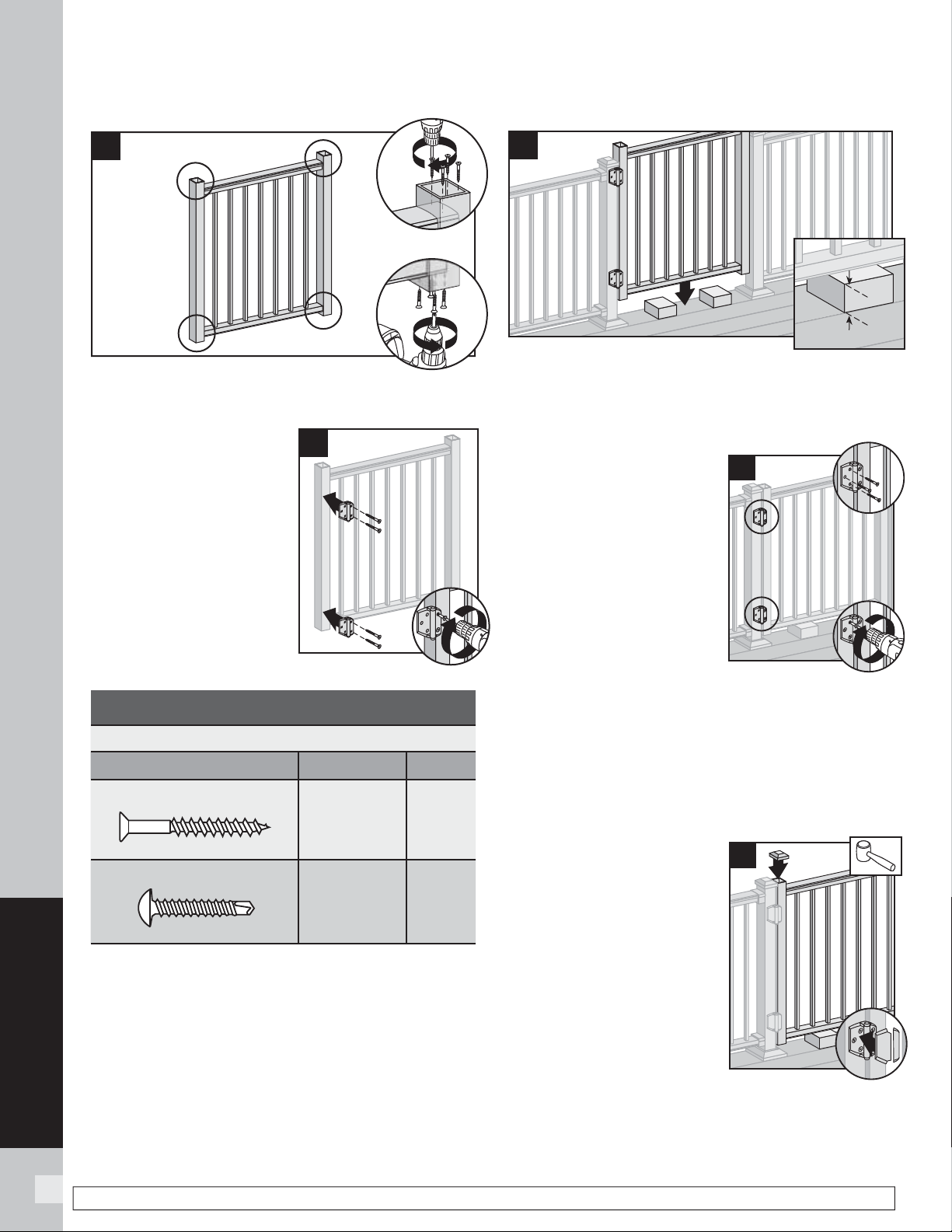
106
SIGNATURE RAILING
NOTE: Construction methods are always improving. Please refer to www.trex.com for the most up-to-date installation requirements.
8. Secure posts to panel with four #8-18 short
self-tapping screws (provided) in each location.
9. Attach shorter side of
hinge to the gate.
NOTE: Refer to
instructions included
in hardware package.
Be sure to use correct
fasteners for aluminum.
See chart below.
NOTE: Use of non-Trex hardware is not
recommended and could result in serious
injury or death.
10. Place gate in opening on blocks. Sweep between
bottom of gate and top of deck cannot exceed
4" (102 mm) per IRC/IBC code regulations. Ensure
bottom gate posts will be high enough to clear skirts
on bottom of deck posts.
11. Make sure posts are plumb
and gate is level. Attach
longer side of hinges to
post using appropriate
hardware for type of post
installed. Install hinge
cover.
NOTES:
» Both wood and
aluminum screws are
included in hardware kit.
(Refer to chart under
Step 9.)
» If using Trex Post Mounts with Post Sleeves,
pre-drilling is required using 1/8" (3 mm) drill
bit, as you must go through both aluminum
sleeve and internal post.
12. After determining location and height of hinge
and hasp, install per
instructions included with
hardware kit.
13. Ensure proper operation
of gate. Hinge tension is
adjustable (check hardware
kit instructions for more
detail).
14. After gate installation,
place blocks under gate
for support. Use a rubber
mallet to install cap onto
gate post. Repeat for other
gate post cap. Snap all
hinge covers into place.
INSTALLING ALUMINUM GATE/CONTINUED
8
1
1
9
2
10
4" max
(102 mm)
4" max
(102 mm)
MINIMUM FASTENER SIZE
SCREWS
Type Length No.
Wood Screw
2-1/2" (64 mm) #9
Metal Screw
2" (51 mm) #8-18
11
2
1
1
14
2
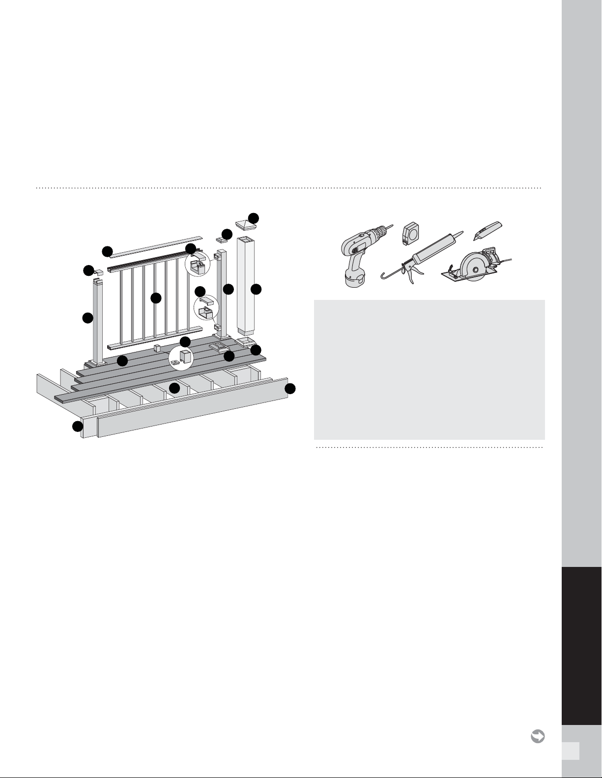
107
SIGNATURE RAILING
C
A
D
K
J
E
B
H
H
I
M
L
N
F
F
GG
NOTES:
» SIGNATURE RAILINGS ARE DESIGNED TO BE ATTACHED WITH POSTS INSTALLED AT A CLEAR SPAN OF 6' (1.83 M) OR 8' (2.44 M).
» IF INSTALLING AT EXACT SPAN LENGTHS OF 6' (1.83 M) OR 8' (2.44 M), AND USING POST-TO-POST CONFIGURATION, THE BOTTOM RAIL WILL NOT
NEED TO BE CUT, BUT THE TOP RAIL WILL NEED TO BE MEASURED AND CUT.
» IF INSTALLING AT EXACT SPAN LENGTHS OF 6' (1.83 M) OR 8' (2.44 M), AND USING CROSSOVER POST CONFIGURATION (SPANS FROM ONE
CROSSOVER POST TO ANOTHER CROSSOVER POST), BOTH THE BOTTOM RAIL AND TOP RAIL WILL NOT NEED TO BE CUT.
» IN ADDITION, AT ALL FINAL END POST CONFIGURATIONS, TOP RAIL WILL NEED TO BE MEASURED AND CUT.
» SEE INFORMATION WITHIN DETAILED INSTRUCTIONS FOR MORE INFORMATION.
» SEE PAGE 54
FOR SKU NUMBERS.
A. Signature upper rail cover*
- 6' (actual length 73-1/2" [1867 mm])
- 8' (actual length 97-1/2" [2477 mm])
B. Signature Panel (includes top and bottom railings and
square balusters)
C. Crossover bracket cover (supplied with crossover post)
D. Signature crossover post**
- 36" (actual length 34-1/2" [876 mm])
- 42" (actual length 40-1/2" [1029 mm])
E. Signature foot block***
F. Signature post skirt or post sleeve skirt**
G. Signature post**
2-1/2"
- 36" (actual length 37" [940 mm])
- 42" (actual length 43" [1092 mm])
or Trex 4x4 post sleeve**
- 36" (actual length 39" [991 mm])
- 42" (actual length 45" [1143 mm])
H. Signature post cap or post sleeve cap**
I. Signature upper rail bracket and cover
J. Signature lower rail bracket and cover
K. Trex decking
L. Code-approved wood joist 2" x 8" (51 mm x 203
mm) or larger
M. Trex™ Fascia
N. Code-approved wood rim joist 2" x 8" (51 mm x
203 mm) or larger
* Covers are slightly longer to accommodate crossover post
applications.
** Item not included in Signature Panel kits. Both 4" x 4" (102 mm
x 102 mm) and 6" x 6" (152 mm x 152 mm) post sleeves are
designed to fit over 4" x 4" pressure-treated post.
*** Required ONLY for all clear span applications over 6' (1.83 m)
when fixed baluster is centered or unsupported spans greater
than 5' (1.52 m). For example, if an 8' (2.44 m) panel is cut into
a 5-1/2' (1.68 m) section, it would require a foot block due to the
off-center placement of the fixed baluster.
NOTE: If installing 42" (1067 mm) railing, and using pressure-treated
posts with Trex post sleeves, ensure that a longer pressure-treated
post is used along with longer post sleeve, both cut to a height of 46"
(1168 mm) from decking surface.
PARTS TOOLS NEEDED
NOTES:
» Trex Assembled Signature Panels DO NOT
come with foot blocks. You must purchase foot
blocks separately. SKU – BKALFTBLK (one per
panel required on spans greater than 6', see note
below***).
» Trex Assembled Signature Panels DO NOT
come with brackets and screws. You must
purchase the horizontal rail hardware separately.
SKU – BKFHBKTAL (one per panel).
TREX SIGNATURE (FORMALLY REVEAL) PANELS
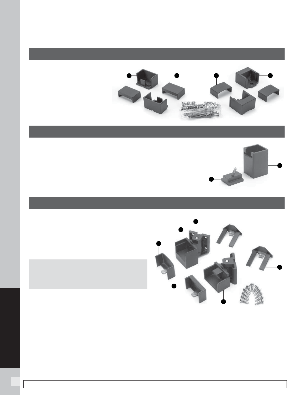
108
SIGNATURE RAILING
NOTE: Construction methods are always improving. Please refer to www.trex.com for the most up-to-date installation requirements.
BRACKET HARDWARE – HORIZONTAL APPLICATIONS
(INCLUDING HORIZONTAL SWIVEL BRACKETS)
TREX SIGNATURE
HORIZONTAL RAILING HARDWARE
AA. Lower rail bracket
BB. Lower rail bracket cover
CC. Upper rail bracket cover
DD. Upper rail bracket
FOOT BLOCK COMPONENTS
EE. Foot block base
FF. Foot block support
HORIZONTAL SWIVEL HARDWARE
GG. Swivel base
HH. Horizontal swivel bracket top rail
II. Horizontal swivel bracket top rail cover
JJ. Horizontal swivel bracket bottom rail cover
KK. Horizontal swivel bracket bottom rail
LL. Swivel base cover
NOTE: For measurements and detailed horizontal
swivel hardware installation instructions, please
see the complete Signature installation section.
FF
EE
GG
LL
KK
JJ
II
HH
AA
BB
CC
DD
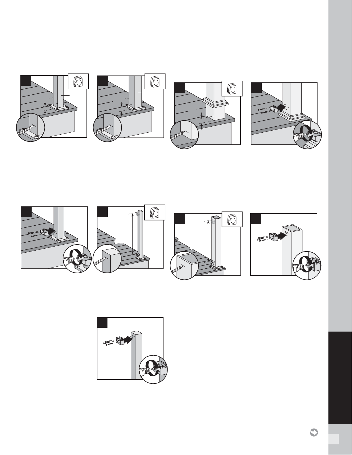
109
SIGNATURE RAILING
HOW TO INSTALL PANELS
TREX SIGNATURE
Attach Brackets Using Signature Posts
TIP: Use a clamp to help hold brackets in place while
fastening with screws.
1a. When using 2" (51 mm) post, for both post-to-post
and post-to-crossover post confi gurations, measure
1-1/2" (38 mm) up from top of post base plate (or
1-7/8" [48 mm] from decking surface). Mark with
light line.
1b. When using 2-1/2" (64 mm) post, measure 1-3/8"
(35 mm) from top of post base plate or 1-7/8"
(48 mm) from decking surface. Mark with light line.
2. Center lower bracket on post above the marked line
and attach using two self-tapping screws (provided).
3. Measure up 32-5/8" (829 mm) for 36" (914 mm) tall
railing or 38-5/8" (981 mm) for 42" (1067 mm) tall
railing from top of lower rail bracket. Mark with
a light line.
4. Center upper bracket
on post below marked
line and attach using
(3) self-tapping
screws (provided).
NOTE: Upper bracket is
not required on crossover
post confi guration.
Attach Brackets Using Pressure-Treated Posts
and Post Sleeves
TIP: Use a clamp to help hold brackets in place while
fastening with screws.
5. Measure 1-7/8" (48 mm) up from deck surface
to bottom of bracket. Slide skirt up to allow for
proper measurement, then push skirt back down
onto surface of decking BEFORE ATTACHING
BRACKET. Mark with light line.
6. Center lower bracket on post above the marked
line and attach using two 2" (51 mm) wood screws
(provided).
7. Measure up 32-5/8" (829 mm) for 36" (914 mm)
tall railing or 38-5/8" (981 mm) for 42" (1067 mm)
tall railing from top of lower rail bracket. Mark with
a light line.
8. Center upper bracket on post below marked line
and attach using three 2" (51 mm) wood screws
(provided).
32-5/8"
(829 mm)
or
38-5/8"
(981 mm)
32-5/8"
(829 mm)
or
38-5/8"
(981 mm)
7
1
8
2
1-1/2"
(38 mm)
1-1/2"
(38 mm)
2" Post
(51 mm)
2" Post
(51 mm)
1a
1-3/8"
(35 mm)
1-3/8"
(35 mm)
2-1/2"
Post
(64 mm)
2-1/2"
Post
(64 mm)
1b
1
2
2
32-5/8"
(829 mm)
or
38-5/8"
(981 mm)
32-5/8"
(829 mm)
or
38-5/8"
(981 mm)
3
1
4
2
1-7/8"
(48 mm)
1-7/8"
(48 mm)
5
1
6
2
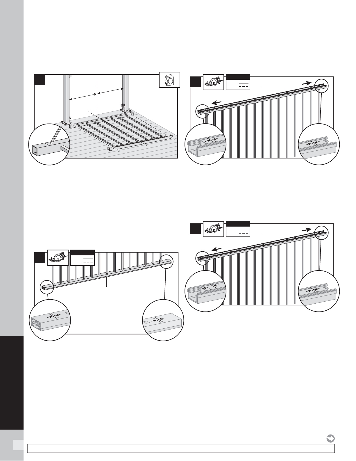
110
SIGNATURE RAILING
NOTE: Construction methods are always improving. Please refer to www.trex.com for the most up-to-date installation requirements.
How to Measure and Cut Bottom and Top
Railings of Signature Panel (When REQUIRED)
1. Position panel between posts and align with bottom
bracket. Align center baluster with middle of span
between posts (this will allow for equal spacing
between end balusters and each post). Mark bottom
and top rail at each end.
NOTE: If the end balusters fall too close to the brackets,
the center point can be adjusted one baluster to the left
or right to allow more room.
Cutting Bottom Rail
2. Using a saw equipped with a non-ferrous metal
blade, cut each end of bottom rail and bottom rail
insert 1/4" (6 mm) shorter than mark on each end to
allow for fi t into bottom rail brackets.
Cutting Top Rail
Option 1:
For Post-to-Post Configuration
3a. Using a saw equipped with a non-ferrous metal
blade, cut each end of top rail 1/4" (6 mm) shorter
than mark to allow for fit into top rail brackets.
Cutting Top Rail
Option 2:
For Post-to-Crossover Post Configuration
3b. Top rail must be cut differently on each side of the
rail. Railing side that attaches to standard post
should be cut 1/4" (6 mm) shorter than the mark
to allow for fit into top rail bracket. Railing side that
attaches to the crossover post should be cut
3/4" (19 mm) LONGER than the mark to allow for fit
into the crossover post bracket.
HOW TO INSTALL PANELS/CONTINUED
TREX SIGNATURE
1
2
1/4"
(6 mm)
1/4"
(6 mm)
1/4"
(6 mm)
1/4"
(6 mm)
KEY
Mark
Cut
KEY
Bottom rail
3a
1/4"
(6 mm)
1/4"
(6 mm)
1/4"
(6 mm)
1/4"
(6 mm)
KEY
Mark
Cut
KEY
Top rail
Standard post
Standard post
3b
1/4"
(6 mm)
1/4"
(6 mm)
3/4"
(19 mm)
3/4"
(19 mm)
KEY
Mark
Cut
KEY
Top rail
Crossover post
Standard post
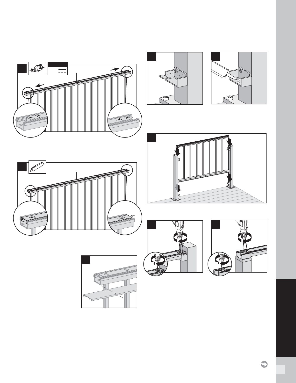
111
SIGNATURE RAILING
Cutting Top Rail
Option 3:
For Crossover Post-to-Crossover Post Configuration
3c. Cut each end of top rail 3/4" (19 mm) LONGER
than the mark to allow for fit into the crossover post
bracket on each side.
4. Using razor knife or other cutting tool, cut rail insert
3/4" (19 mm) FROM EACH SIDE.
5. Mark and cut top rail
cover same length as
top rail for all top rail
confi gurations.
Install Signature Panel
6. Break or cut the bottom tab off the bottom brackets.
7. Put a dab of silicone in the basket of the bottom
bracket to prevent rattle.
8. Place panel in bottom and top brackets.
9. For post-to-post confi guration, fasten upper rail to
each bracket by installing screws diagonally through
upper rail into bracket using two self-tapping screws
each side (provided with bracket kit).
10. For crossover post confi guration, fasten upper rail
to crossover post by installing screws diagonally
through upper rail into post using two self-tapping
screws each side (provided with bracket kit).
NOTE: Pre-drilling is recommended (7/64" [2.8 mm]
drill bit) for attachment of railing to bracket.
3c
3/4"
(19 mm)
3/4"
(19 mm)
3/4"
(19 mm)
3/4"
(19 mm)
KEY
Mark
Cut
KEY
Top rail
Crossover post
Crossover post
4
3/4"
(19 mm)
3/4"
(19 mm)
3/4"
(19 mm)
3/4"
(19 mm)
Top rail
8
5
6
7
HOW TO INSTALL PANELS/CONTINUED
TREX SIGNATURE
2
10
1
7/64"
(2.8 mm)
7/64"
(2.8 mm)
2
9
1
7/64"
(2.8 mm)
7/64"
(2.8 mm)
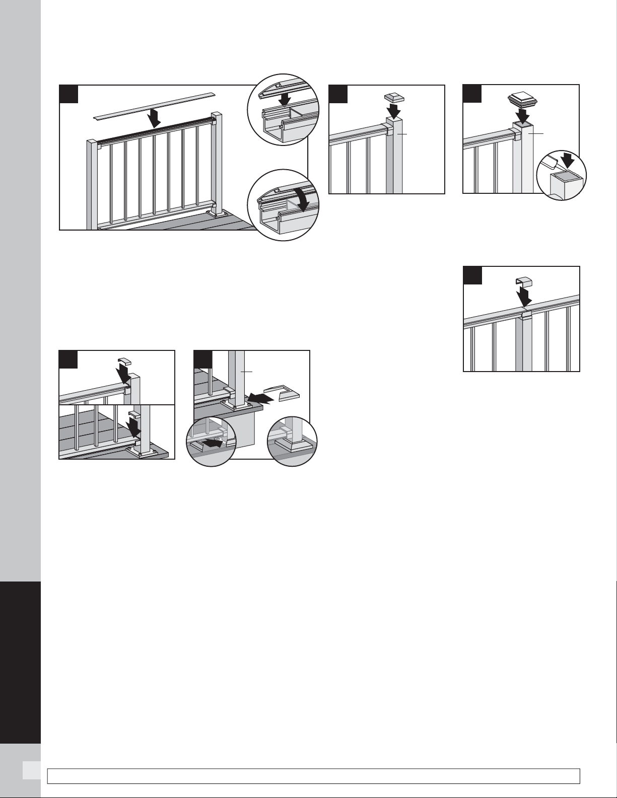
112
SIGNATURE RAILING
NOTE: Construction methods are always improving. Please refer to www.trex.com for the most up-to-date installation requirements.
11. Attach upper rail cover to upper rail by aligning
cover on one side of rail. Then starting from one end
of rail, snap cover onto opposing slot working down
length of rail. A rubber mallet may facilitate the
fastening, using GENTLE tapping.
Attachment of Bracket Covers, Skirts, and Caps
12. Attach corresponding bracket covers over opening
in upper and bottom rails.
13. Attach provided post skirt to bottom of posts when
using Signature posts.
14. Attach post caps to Signature posts (use of rubber
mallet may be required for secure attachment).
15. Attach post caps to post sleeves using external
grade PVC construction adhesive.
16. For crossover post
confi guration, attach
crossover post cap to
crossover post.
HOW TO INSTALL PANELS/CONTINUED
TREX SIGNATURE
1
11
3
2
1
14
Signature
post
2
Post
sleeve
15
3
1
1
13
Signature
post
2
1
2
12
16
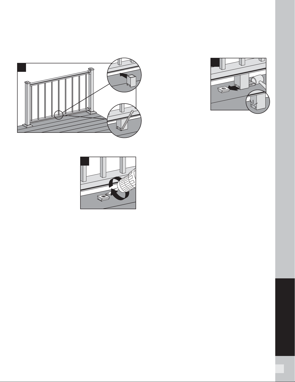
113
SIGNATURE RAILING
HOW TO INSTALL FOOT BLOCKS – PANELS
TREX SIGNATURE
Attachment of Foot Block (Required ONLY for All
Clear Span Applications Over 6
'
[1.83 m])
1. To ensure correct location, place foot block under
center of bottom rail. Mark to provide placement
location of base.
2. Place base (smaller
side facing down)
on decking surface.
Attach base of foot
block using one screw
at an angle through
base and into decking.
NOTE: Pre-drilling is recommended (1/8" [33 mm]
drill bit) for attachment of base.
3. After attached, use a
rubber mallet along
with scrap piece of
wood to tap foot block
until it locks into place.
1
2
1
2
1
3
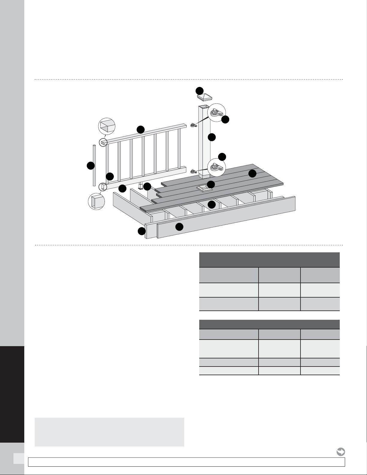
114
SELECT RAILING
TREX SELECT RAILING
NOTES:
» All Trex Select Railing lengths are manufactured at ON CENTER dimensions (spanning from center of each post): 67-5/8" (176.8 cm) for 6' (1.83
m) on center, and 92-5/8" (235.3 cm) for 8' (2.44 m) on center. Note that railings are designed to be slightly longer that required to allow for very
slight play in post placement – trimming may be required. IT IS VERY IMPORTANT TO MEASURE FIRST.
» SEE PAGE 56 FOR SKU NUMBERS.
PARTS
A. Select top rail
B. Select bottom rail
C. Brackets
D. Balusters
E. Adjustable foot block
F. Post sleeve cap*
G. Post sleeve skirt*
H. Post sleeve – 4" x 4" (102 mm x 102 mm) or
6" x 6" (152 mm x 152 mm) post sleeve)**
I. Trex decking
J. Trex fascia
K. Code-approved wood joist – 2" x 8"
(51 mm x 203 mm)
L. Code-approved wood rim joist – 2" x 8"
(51 mm x 203 mm) or larger
* Item not included in the Select railing kits.
** Both 4" x 4" (102 mm x 102 mm) and 6" x 6" (152 mm x 152 mm) post
sleeves are designed to fit over 4x4 pressure-treated post.
A
B
C
C
D
F
*
G
*
H
**
I
J
K
L
E
O
NOTE: Pictorial representations shown may only show one style of railing,
while others may also be used. Review detailed instructions to determine
what railing styles and combinations can be used.
NOTE: If installing 42" (1067 mm) railing, use longer posts sleeves
and measure accordingly to ensure a proper cut (DO NOT CUT POST
SLEEVES TO ACTUAL 42" – THESE NEED TO BE LONGER TO ALLOW
FOR POST CAPS TO FIT).
DETERMINING BALUSTERS NEEDED
Baluster Type
Per 6' OC
Section
Per 8' OC
Section
Round Aluminum Baluster
(Horizontal Application)
14 20
Round Aluminum Baluster
(Stair Application)
12 17
CODE APPROVED APPLICATIONS
6' Railing 8' Railing
< 30" height decking
Acceptable
(Code approval
not applicable)
Acceptable
(Code approval
not applicable)
IRC Compliant
Ye s N o
IBC Compliant
No No
NOTE: Construction methods are always improving. Please refer to www.trex.com for the most up-to-date installation requirements.
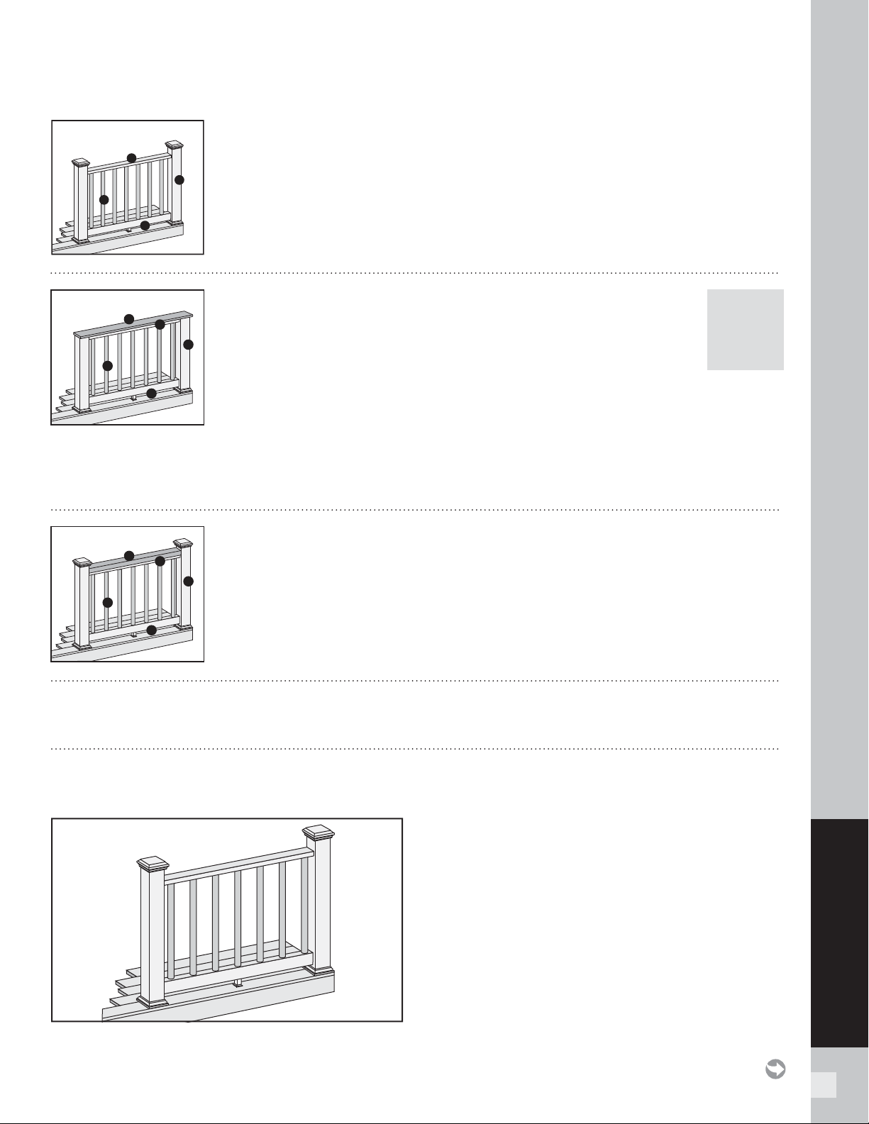
115
SELECT RAILING
TREX SELECT RAILING
RAILING CONFIGURATIONS
Cutting post sleeves is NOT required.
A. Pressure-treated post or Trex post mounts* with Trex Transcend post sleeves, or Trex
joist mount posts*
B. Select top rail
C. Select bottom rail
D. Select balusters
See page 115 for “How to Install Standard Railing”.
Cutting post sleeves is NOT required.
A. Pressure-treated post or Trex post mounts* with Trex Transcend post sleeves, or Trex
joist mount posts*
B. 2" x 4" (51 mm x 102 mm) lateral top rail
C. Select top rail
D. Select bottom rail
E. Select balusters
See page 119 for “How to Install Traditional Railing”.
Post sleeves WILL NEED TO BE CUT.
A. Pressure-treated post with Trex Transcend post sleeve
NOTE: » Only for use with 4" x 4" (102 mm x 102 mm) post sleeve.
» Trex post mounts or joist mount posts cannot be Select
cocktail design.
B. Deck board top rail.
NOTES: » Contour and Escapes cannot be used
» Deck boards will need to be cut to fi t each rail span
C. Select top rail
D. Select bottom rail
E. Select balusters
See page 118 for “How to Install Select Cocktail Railing”.
A
B
C
D
POST
SLEEVES
WILL
NEED TO
BE CUT
Standard
A
B
D
C
E
Cocktail
A
B
D
C
E
Traditional
*See specifi c installation instructions for attachment of Trex post mounts or Trex Joist Mount Posts prior to
installing any railing.
HOW TO INSTALL TREX SELECT STANDARD RAILING
TREX SELECT
Read all instructions BEFORE installation.
Important: Post sleeves are NOT to be cut for this
design style.
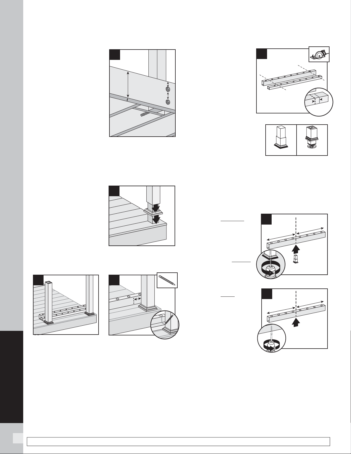
116
SELECT RAILING
NOTE: Construction methods are always improving. Please refer to www.trex.com for the most up-to-date installation requirements.
HOW TO INSTALL TREX SELECT RAILING/CONTINUED
TREX SELECT
Installing Pressure-
Treated Posts
» Select Railing Kits are
designed for posts to
be installed at maximum
of 6' or 8' (1.83 m or
2.44 m) ON CENTER
depending on the length
being used.
(NOTE: Smaller spans are
allowed).
» Attach posts using
1/2" (13 mm) carriage
bolts.
» Minimum joist size is 2" x 8" (51 mm x 203 mm).
» Top bolts must be 1" (25 mm) from tops of joists.
» Bottom bolts must be 5-1/8" (130 mm) from top bolts.
NOTE: Blocking MUST be added for extra strength.
Installing Post Sleeve
Skirts and Post Sleeves
2. Slide post sleeve skirt
over post and down to
rest on decking surface.
Slide post sleeve over
post and position inside
post sleeve skirt.
NOTE: Shims can be used
to plumb post sleeves.
Cutting Railings
3a. Position bottom and top rails between posts,
ensuring baluster holes are lined up and spaced
evenly.
3b. Also allow for a minimum of 1-9/16" (40 mm) on
each end of rail for bracket placement AND baluster
clearance. Mark rails at intersection of rail and post.
3c. Cut each end of both
bottom and top rails
1/4" (6 mm) shorter
than mark on each
end to allow for fi t into
brackets.
NOTE: After cutting, this
still allows enough space
for bracket placement.
IMPORTANT NOTE
REGARDING FOOT BLOCK
INSTALLATION:
» Determine which style
of foot block is included.
Original foot block is a one-piece part that is
adjustable. New foot block is a two-piece part with
turning base mount.
» Also refer to detailed instructions (Trex Select®)
rail instructions) included with foot block prior to
installation of railing section as these include other
required steps for proper installation.
If Attaching Original
Foot Block to Bottom
Rail
4a. Invert the bottom
railing. Center foot
block on the bottom rail
and attach per Original
Foot Block instructions.
If Attaching New Foot
Block to Bottom Rail
4b. Invert the bottom
rail. Center and drill
a hole using a 3/16"
drill bit. This will be
location for foot block
attachment(to be
installed last).
1
5-1/8" (130 mm) min.
2" x 8"
(51 mm x
203 mm)
min.
1" (25 mm) min.
1
2
2
3a
1-9/16"
(40 mm)
3b
3c
1/4"
(6 mm)
Original
New
1
4a
2
1
4b
2
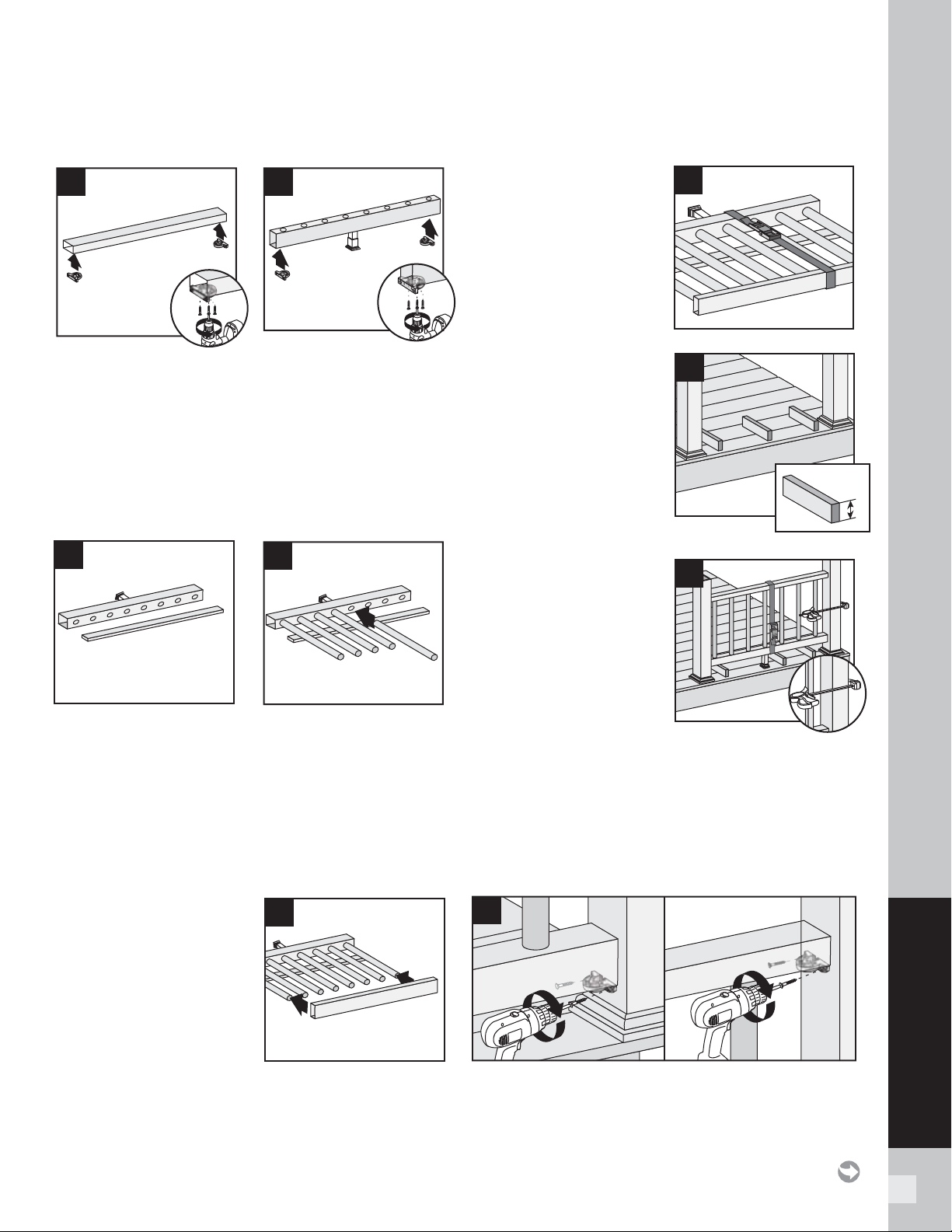
117
SELECT RAILING
Attaching Brackets to Rails
5a. Position brackets on each end of TOP RAIL on the
same side as baluster holes. Attach brackets using
three #8-18 x 1" self-drilling
screws (provided).
5b. Position brackets on each end of BOTTOM RAIL on
the OPPOSITE SIDE of the baluster holes. Attach
brackets using three #8-18 x 1" self-drilling screws
(provided).
Assembling Railing Section
6a. On a clean fl at surface lay bottom railing on its side.
Make sure to allow enough room for installation
of balusters and top rail. Place a scrap piece of
1" decking board running parallel to bottom rail for
support when installing balusters.
6b. Insert balusters into bottom rail slots until balusters
are fully seated.
6c. Attach top rail to
balusters, feeding each
baluster into required
slots. Start on one end
and work towards the
other.
6d. To help temporarily
secure the railing
section together, place a
ratchet strap around the
top and bottom rail and
tighten until snug. DO
NOT OVERTIGHTEN
AS YOU CAN BEND
THE RAILING.
Installing Railing
Section to Posts
7a. Using scrap material (i.e.
2 x 4s, decking boards,
etc.) cut at least three
support blocks at 3-3/4"
in height. Place one
each on decking surface
beside each post and
one near center of span.
7b. Lift secured railing
section up, and
CENTER this section in
between the spanned
posts on pre-positioned
support blocks.
NOTE: To help stabilize
railing section use a quick-
grip clamp (or other type of
clamp) and clamp the fi rst baluster to post sleeve.
(DO NOT OVERTIGHTEN CLAMP.)
7c. Install both bottom and top brackets on each
side to post using two #8-10 x 2" wood screws
(provided). For best results, set drill to low speed
when installing these screws.
7a
3-3/4"
7b
6c
6d
6a
6b
5b
Bottom Rail
7c
5a
Top Rail
HOW TO INSTALL TREX SELECT RAILING/CONTINUED
TREX SELECT
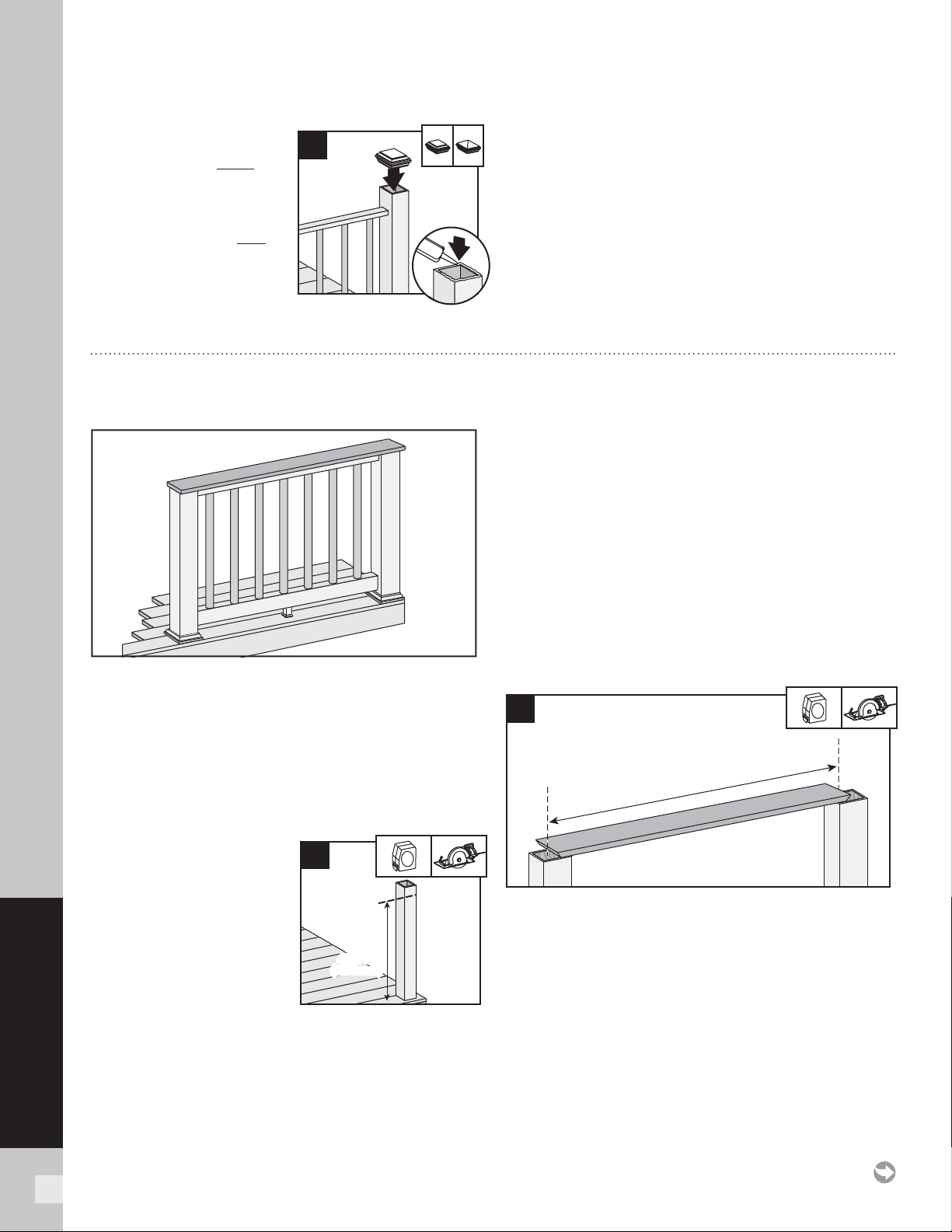
118
SELECT RAILING
HOW TO INSTALL TREX SELECT RAILING/CONTINUED
TREX SELECT
Attaching Post Caps
and Installing New
Foot Block
8. Secure post caps
with silicone or PVC
adhesive. Attach new
foot block per foot
block instructions.
NOTE: Clean up any excess
adhesive before drying.
2
8
1
Important: ONLY use for use with pressure-treated
4x4 post (3.5" nominal square) and 4" x 4" (102 mm x
102 mm) post sleeve. Trex Post Mounts or Joist Mount
Posts cannot be used with Select Cocktail railing.
1.
Installing Pressure-Treated Posts, Post
Sleeve Skirts and Post Sleeves
See instructions on page 116.
Cutting Post and Post
Sleeve
1a. Mark and cut post and
post sleeve measuring
from deck surface:
» 36-1/8" (918 mm) for
36 " (914 mm) height.
» 42-1/8" (1070 mm) for
42 " (1067 mm) height.
4. Cutting Railings
See instructions on page 117.
5.
Attaching Foot Block to Bottom Railing
See instructions on page 117.
NOTES:
»
If installing in weather below 40°F (4.5°C), leave 1/8 "
(3 mm) gap between deck boards.
»
Deck boards can overhang end of last post
maximum 1/2" (13 mm).
Cutting Deck Board
6. Cut deck boards to appropriate length of railing
span, remembering to include extra space on each
side of the deck board to allow for attachment to
the post. Decking boards must cover 1/2 of the
pressure-treated post to allow this to be
fastened later.
36-1/8"
(918 mm)
or
42-1/8"
(1070 mm)
36-1/8"
(918 mm)
or
42-1/8"
(1070 mm)
1a
HOW TO INSTALL COCKTAIL RAILING
TREX SELECT
6
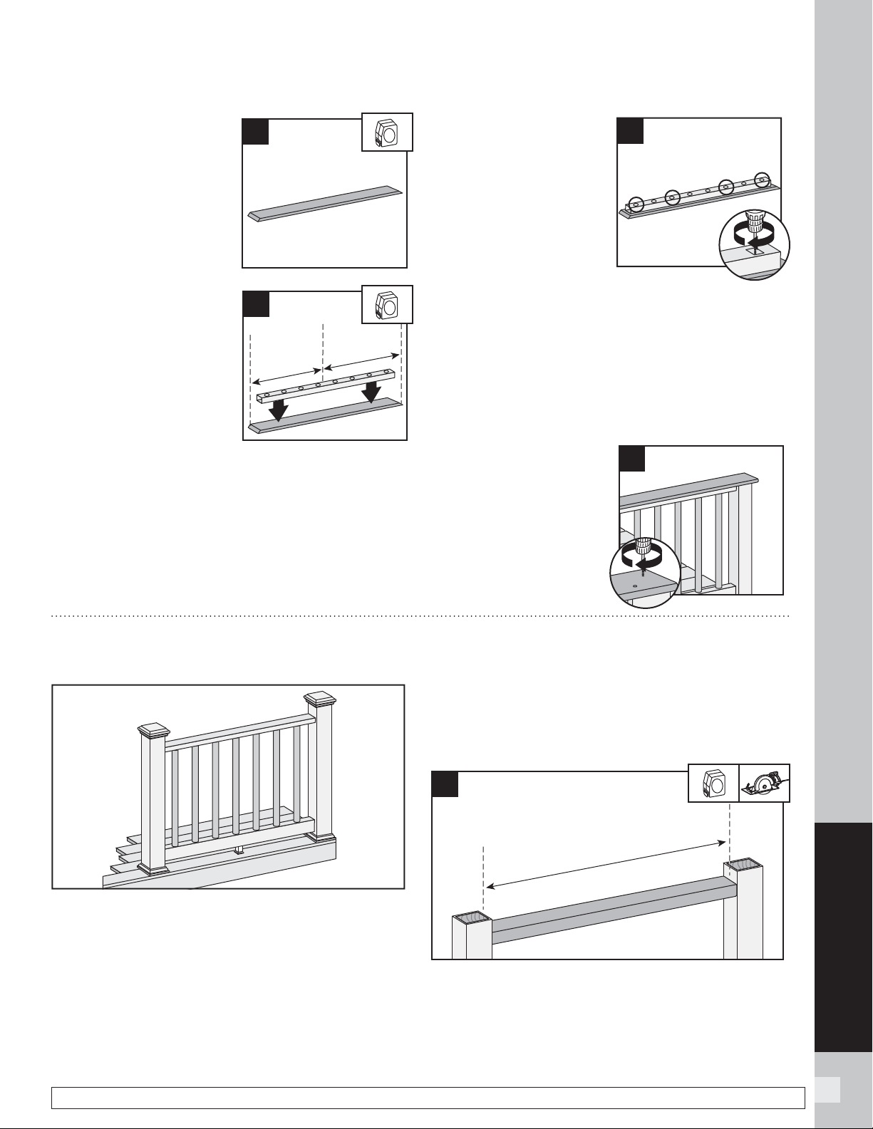
119
SELECT RAILING
HOW TO INSTALL TREX SELECT RAILING/CONTINUED
TREX SELECT
NOTE: Construction methods are always improving. Please refer to www.trex.com for the most up-to-date installation requirements.
7. Place inverted deck
board (place top side
of deck board down) on
clean, fl at surface. (DO
NOT use Escapes, or
Contour deck boards for
top rail.)
Attaching Deck Board
to Select Top Rail
8. Place inverted Select top
rail (orient properly so
baluster holes are shown
top side up), on the deck
board, centered in both
directions to allow fi nal
attachment to post.
9. Secure deck board
to Select top rail with
3/4" screws provided
approx. every 16" on
center. Screws are to be
installed inside of the
baluster holes into the
decking board. DO NOT
overtighten.
NOTE: A long drill bit will be required to fit inside the
baluster holes.
10.
Assembling Railing Sections
See instructions on page 117.
11.
Installing Railing Sections to Posts
See instructions on page 117.
12.
Attaching Deck
Board to Posts
Attach boards on
each post with Trex
recommended
composite screws
(quantity of 2 per each
board end).
8
9
12
7
HOW TO INSTALL TREX TRADITIONAL RAILING
TREX SELECT
1. Installing Pressure-Treated Posts, Post
Sleeve Skirts and Post Sleeves
See instructions on page 116.
2.
Attaching Foot Block to Bottom Railing
See instructions on page 116.
3.
Cutting Railings
See instructions on page 116.
Cutting 2" x 4"
4. Cut 2" x 4" (51 mm x 102 mm) to same length of the
inverted Select top rail.
4
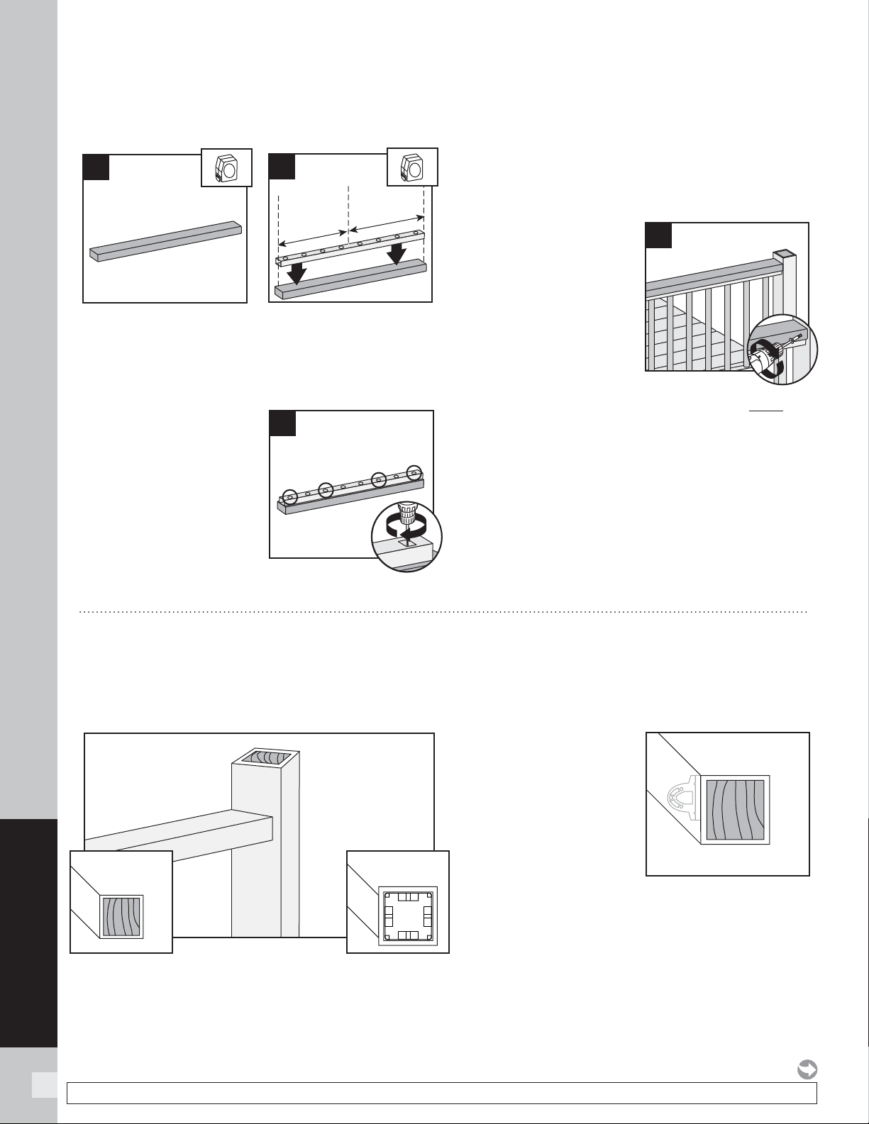
120
SELECT RAILING
NOTE: Construction methods are always improving. Please refer to www.trex.com for the most up-to-date installation requirements.
HOW TO INSTALL TREX SELECT RAILING/CONTINUED
TREX SELECT
Attaching 2" x 4" to Select Top Rail
5. Place inverted 2" x 4" (51 mm x 102 mm) (place
topside down) on clean, fl at surface.
6. Place inverted Select top (orient properly so
baluster holes are shown top side up) on 2" x 4"
(51 mm x 102 mm).
7. Secure 2" x 4" (51 mm
x 102 mm) to Select
top rail with 3/4" screw
provided approx. every
16" on center. Screws
are to be installed inside
of the baluster holes into
the decking board.
DO NOT overtighten.
Note that a long drill bit
will be required to fi t inside the baluster holes.
8. Assembling Railing Sections
See instructions on page 117.
9.
Installing Railing Sections to Posts
See instructions on page 117.
10.
Attaching 2x4 to
Posts
Pre-drill a pilot hole and
toenail 2-1/2" (64 mm)
screw at each end of 2"
x 4" (51 mm x 102 mm)
intopost on back side
of rail (side not facing
decking).
11.
Attaching Post Caps and Installing New
Foot Block
See instructions on page 118.
6
5
7
1
10
HOW TO INSTALL ON-AN-ANGLE RAILING
TREX SELECT
NOTE: Brackets are designed to be installed up to a
45° angle.
Both 4" x 4"
(102 mm x 102 mm)
or
6" x 6" (152 mm x 152 mm)
post sleeves work well for
angles up to 45 degrees.
Bottom rail brackets may
need to be slightly offset
to one side in order to fi t
properly to hold rail in place
Measure and mark fi rst before attachment of bracket
to rail to ensure bottom rail remains parallel to upper
rail.
4 x 4 OR 6 x 6
Post Sleeve
4 x 4
Post Sleeve
6 x 6
Post Sleeve
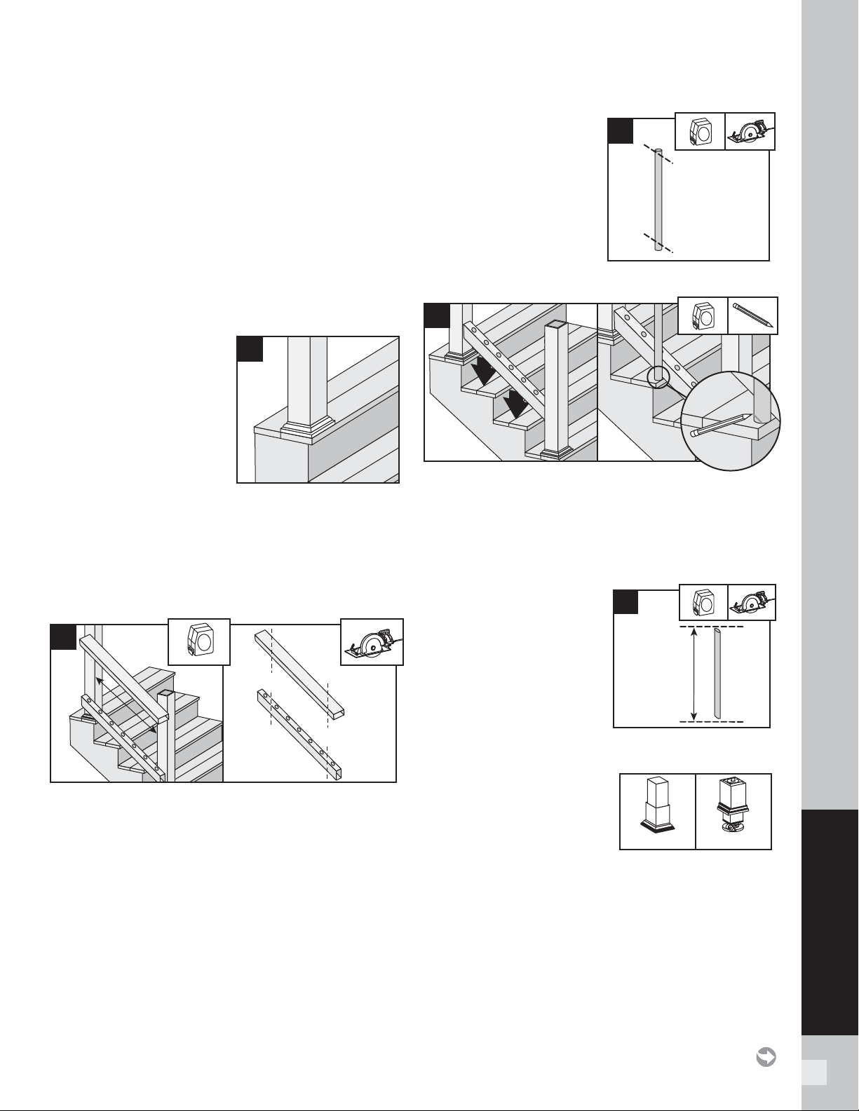
121
SELECT RAILING
HOW TO INSTALL TREX SELECT STAIR RAILING
TREX SELECT
Read all instructions BEFORE installation.
IMPORTANT NOTE: POST TO POST SPAN WILL
BE LESS THAN 6’. PRIOR TO INSTALLING POSTS
CALCULATE POST TO POST SPAN USING A
MAXIMUM RAIL LENGTH OF 6’ AND THE
ANGLE (32°-37°) AT WHICH THE RAILS WILL BE
INSTALLED. DO NOT INSTALL STAIR POSTS AT
6' SPAN, AS STAIR RAILINGS WILL THEN BE TOO
SHORT.
NOTE: All Select railings work ONLY WITH STAIR
SLOPES OF 32° TO 37°.
Installing Posts, Post
Sleeve Skirts, and Post
Sleeves for Stair Rails
1. Install posts, post
sleeve skirts, and post
sleeves according to
standard Select railing
instructions.
» In most cases, a post and post sleeve longer than
39" (991 mm) will be needed on the lower section
of stair rail to accommodate stair angle.
» Make sure top and bottom posts for stairs are
installed at nose of each tread.
Measuring and Cutting Railings
2. Set railing along the nose of the stair treads, making
sure baluster holes are vertically aligned and mark
line at each intersection. When measuring, cut
equal lengths from each side of railing allowing
a minimum of 2" on each end from the last
baluster hole to the end of the rail. This will
ensure proper baluster and bracket placement and
equal spacing of balusters per each railing section.
Cutting Balusters on
Angle (OPTIONAL)
3a. In order for balusters
to seat properly
(depending on the
angle of the stair
railing), the balusters
may need to be
trimmed to match the
angle of the bottom and top railing.
3b. Set bottom railing on nose of stair treads and set
baluster at 90º on the outside of the railing, mark
and measure the angle.
NOTE: Measure, mark, and cut a scrap board to ensure
you have proper angle BEFORE cutting balusters on angle.
3c. Cut the VERY END
of baluster, both top
and bottom, making
sure that point to point
measurement of the
baluster remains at either
32" (813 mm) for 36" (914
mm) rail heights or 38"
(965 mm) for
42" (1067 mm) rail heights.
IMPORTANT NOTE
REGARDING FOOT BLOCK
INSTALLATION:
» Determine which style
of foot block is included.
Original foot block is a one-piece part that is
adjustable. New foot block is a two-piece part with
turning base mount.
» Also refer to detailed instructions (Trex Select)
rail instructions) included with foot block prior to
installation of railing section as these include other
required steps for proper installation.
1
3a
2
3b
32" (813 mm)
or
38" (965 mm)
3c
Original
New
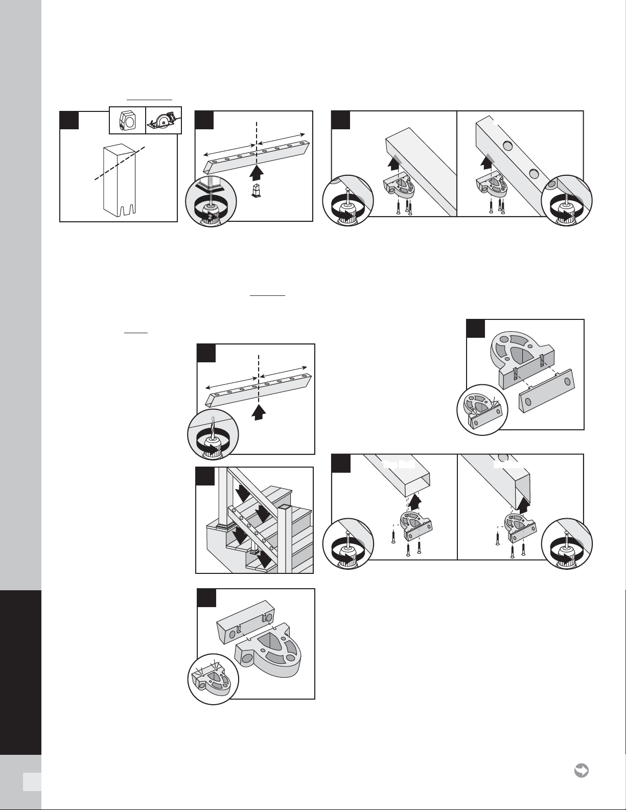
122
SELECT RAILING
HOW TO INSTALL TREX SELECT STAIR RAILING/CONTINUED
TREX SELECT
If Attaching Original Foot Block to Bottom Rail
4a.
For stair applications, cut the section of foot block at
an angle to match rail. Refer to foot block instructions
for specifi c information on how to do this.
4b. Invert bottom rail. Center foot block on bottom
rail and attach at marked position per Original foot
block instructions. DO NOT extend foot block.
If Attaching New Foot Block to Bottom Stair Rail
4c. Invert the bottom stair
rail. Center and drill a
hole using a 3/16" drill
bit. This will be location
for foot block (to be
installed last).
Attachment of
Brackets to Railings
5a. Check fi t for both top
and bottom railings in
designated positions
for location onto posts.
Remove railings.
Upper Stair Post
Locations
5b. Snap the top stair
adaptor bracket
(labeled TOP) to the
standard bracket.
Repeat for remaining
bracket.
Upper Stair Post Locations
5c. On the TOP RAIL, attach the assembled top stair
bracket to the side with baluster holes. On the
BOTTOM RAIL, attach the assembled top stair
bracket to the OPPOSITE SIDE of the baluster
holes. Attach both brackets using three #8-18 x 1"
self-drilling screws (provided).
Lower Stair Post
Locations
5d. Snap the bottom
stair adaptor bracket
(labeled BOTTOM) to
the standard bracket.
Repeat for remaining
bracket.
5e. On the TOP RAIL, attach the assembled bottom
stair bracket to the side with baluster holes. On
the BOTTOM RAIL, attach the assembled bottom
stair bracket to the OPPOSITE SIDE of the baluster
holes. Attach both brackets using three #8-18 x 1"
self-drilling screws (provided).
4a
1
4b
2
4c
5a
5d
1
1
5c
Top Rail Bottom RailBottom Rail
22
5b
1
1
5e
Top RailTop Rail Bottom RailBottom Rail
22
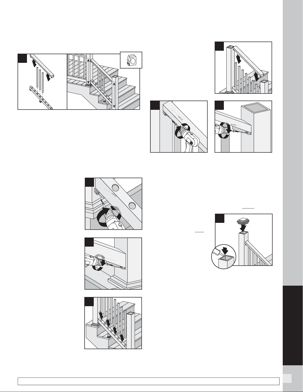
123
RAILING
123
SELECT RAILING
HOW TO INSTALL TREX SELECT STAIR RAILING/CONTINUED
TREX SELECT
NOTE: Construction methods are always improving. Please refer to www.trex.com for the most up-to-date installation requirements.
Attachment of Bottom Rail to Post
6a. Assemble a few of the balusters into the bottom
and top railings (make sure balusters are setting
at 90º) and set this on scrap material clearing the
stair treads to determine where bracket locations
need to be. Measure to make sure that the bottom
railing will clear the stair treads and the top railing
will be aligned with horizontal railing (remember
in most cases, a longer post and post sleeve will
be needed on the lower section of stair rail to
accommodate stair angle).
6b. After locating
appropriate position for
bottom rail remove top
rail and balusters and
attach bottom rail stair
bracket to upper post
using two
#8-10 x 3" wood screws
(provided).
6c. Attach bottom stair
rail stair bracket to
lower post using two
#8-10 x 3" wood screws
(provided). For best
results set drill to low
speed when installing
these screws.
Install Balusters
7. Slide balusters into
bottom rail until
balusters are fully
seated.
Attachment of Top
Rail to Post
8a. Place top rail onto
balusters, allowing the
top rail to rest on the
surface of the balusters.
8b. Attach top stair rail bracket to upper post using two
#8-10 x 3" screws (provided). For best results set
drill to low speed when installing these screws.
8c. Attach top stair rail bracket to lower post using two
#8-10 x 3" screws (provided). For best results set
drill to low speed when installing these screws.
Attaching Post Caps and Installing New Foot
Block
9. Secure post caps
with silicone or PVC
adhesive. Attach new
foot block per foot
block instructions.
NOTE: Clean-up any
excess adhesive before
drying.
6a
6b
6c
8a
7
8b
8c
2
9
1
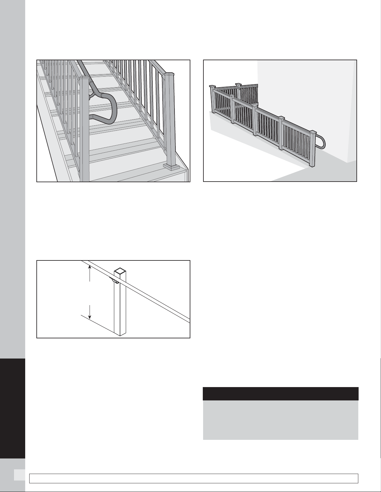
124
ADA RAILING
124
NOTE: Construction methods are always improving. Please refer to www.trex.com for the most up-to-date installation requirements.
TREX ALUMINUM ADA COMPLIANT HANDRAIL
STAIR APPLICATION
ADA Handrail Guidelines
1. ADA handrails can be installed using various design
applications such as those for stairs, ramps, and
horizontal applications. Designs include options
for straight and 90° wall returns, 90° corners, and
adjustable angles. Choose which is best for your
needs before installing. Refer to railing profi les
(page 56) for a more detailed parts list.
2. The handrail system top rail should be 34"
(864 mm) to 38 " (965 mm) above the surface.
However, verifying height requirements with local
building code offi cials before installing is important
as codes vary in different areas.*
3. Maintain a minimum clearance of 1-1/2 " (38 mm)
between the handrail and any obstructions above
or behind the handrail.
4. The end loop return at all landings must extend
12 " (305 mm) past the end of the ramp or stair
application.*
5. The slope of the handrail for the ramp should not
exceed 1 " (25 mm) rise over a 12 " (305 mm) run.
6. The maximum recommended span between
supports is 6' (1.83 m) on center. Thus
placement of posts is critical when installation
of railing is being considered.*
7. Rails are designed to have a tight fit into other
connecting components. It is critical to line these
up in the correct orientation BEFORE connecting
parts together. If it is necessary to shift or move a
component on a rail, wrap with a protective cloth
to prevent scratching as you may need to use a
wide-mouth wrench to correct this.
8. At any straight location where internal
connector is used, it is CRITICAL to locate
these as close to a wall mount as possible.
9. If using metal posts, pre-drill all locations for
bracket attachment. (ALWAYS use a drill bit
slightly SMALLER in diameter than the screw
being used for attachment.)
10. All elbow components can be cut down to allow
for tighter angles. Cut a maximum of 2" (51 mm)
on each side if this is required.
*Refer to the American Disabilities Act for detailed
information in regards to handrail requirements.
34" (864 mm)
to
38" (965 mm)
RAMP APPLICATION
» When cutting metal, ALWAYS wear proper safety
eyewear (as well as any other proper safety wear).
» Remove all burrs from cut ends before installation.
» Use of a non-ferrous metal blade is recommended.
SAFETY NOTES
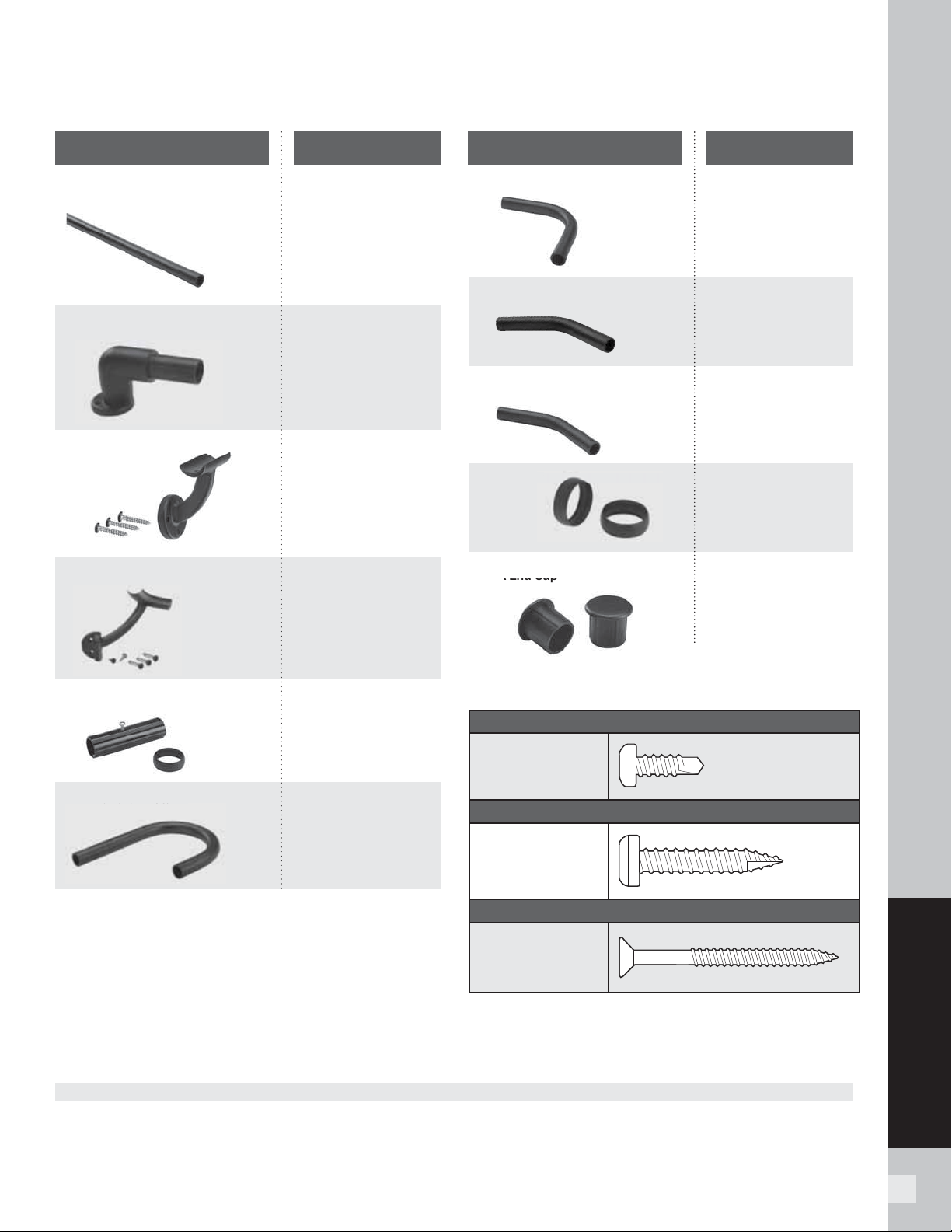
125
ADA RAILING
125
ADA RAILING PROFILES
ADA 90° Elbow BK, BZ, WT
ADA 36°, 34°, and 31° Elbows BK, BZ, WT
ADA 5° Elbow BK, BZ, WT
ADA Collar BK, BZ, WT
ADA End Cap BK, BZ, WT
DESCRIPTION DESCRIPTION
ADA Hand Rail BK, BZ, WT
1.385" (35 mm) diameter
ADA Wall Return BK, BZ, WT
ADA Wall Mount BK, BZ, WT
ADA Corner Mount* BK, BZ, WT
ADA Internal Connector
ADA Handrail Return BK, BZ, WT
A
Wall
Mount
A
End
C
ap
ar
COLORS: BK Charcoal Black BZ Bronze WT White
COLOR COLOR
ADA
Handrail
Return
* Can only be used with metal post horizontal
applications.
NOTE: If attaching brackets to 6x6 posts/post sleeves,
use 8-10 x 2-1/2" (64 mm) wood screws (not included).
HARDWARE
RAIL TO BRACKET ATTACHMENT
Short Metal Screw
(#10 x 5/8" [16 mm])
BRACKET TO METAL POST ATTACHMENT
Long Metal Screw
(#12 x 1-1/4"
[32 mm])
BRACKET TO WOOD POST/POST SLEEVE ATTACHMENT
Wood Screw
(8-10 x 2" [51 mm])
» SEE PAGE 56 FOR SKU NUMBERS.
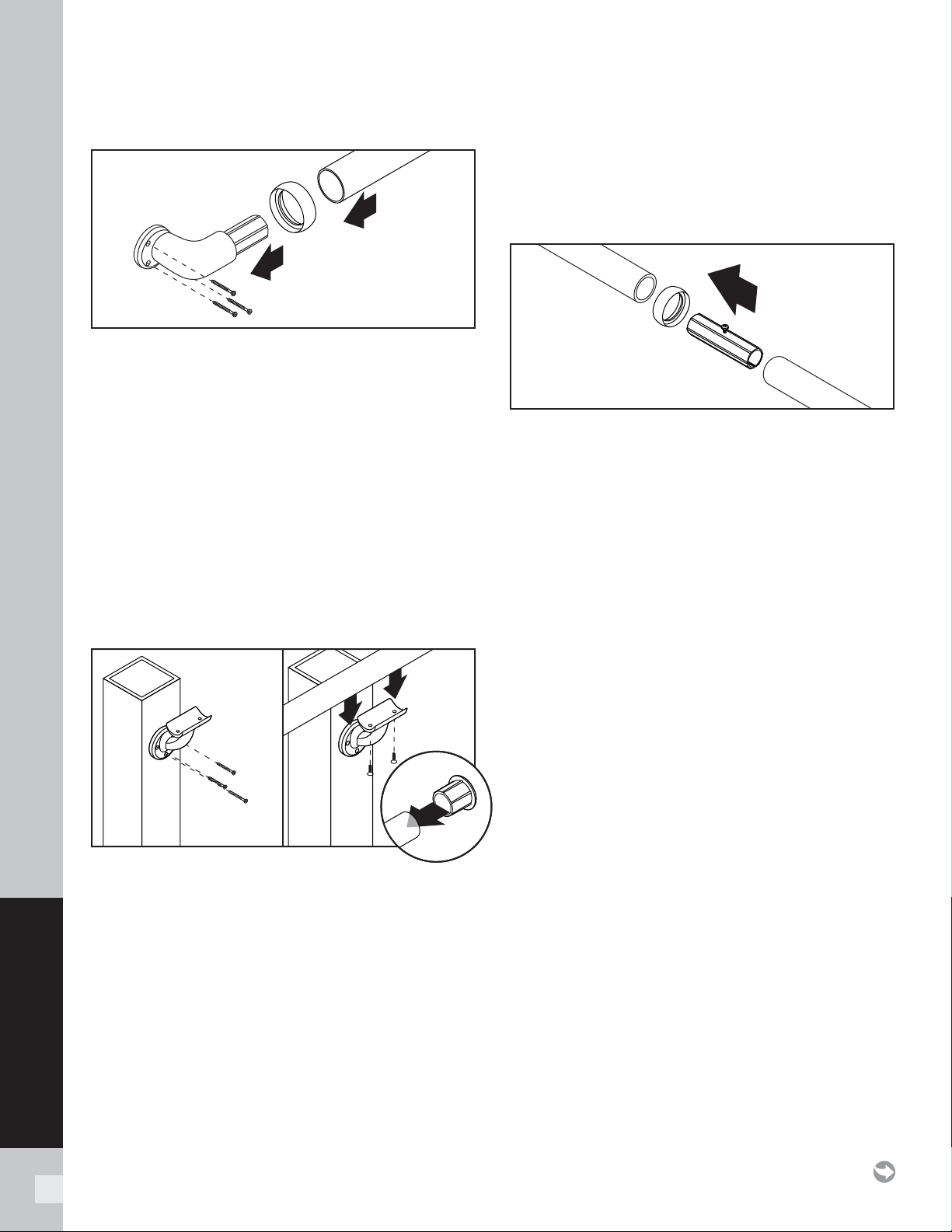
126
ADA RAILING
90° Wall Return
1. If required, cut railing to proper length based on
location of wall return(s) or attachment to other
components.
2. If desired, collar ring can be used to hide seam of wall
return to rail. Slide this over rail BEFORE inserting rail
into wall return.
3. Slide rail onto wall return until it is fully inserted and
seam is hidden under collar (if collar is being used).
4. Attach wall return to post using specifi c hardware
provided (see chart on previous page), ENSURING
wall return is at proper angle of alignment to post.
(Wall return is designed to have tight fi t into rail, thus
location of attachment is critical.) If using metal posts,
pre-drill post prior to attachment of wall mount.
Wall Mount
NOTE: Refer to Rail-to-Rail Connections section
if connecting two or more rails together to make
continuous straight run.
1. If required, cut railing to proper length based on
location of wall mount(s) or attachment to other
components.
2. Attach wall mount to post using specifi c hardware
provided (see chart on previous page), ENSURING
wall mount is at proper angle of alignment to angle
of rail. If using metal posts, pre-drill post prior to
attachment of wall mount.
TIP: To help with angled attachment, place one screw
into bottom hole of bracket and pivot wall mount to
position required.
3. Attach rail to wall mount using specifi c hardware
provided (see chart on previous page).
4. Attach end cap to railing.
Rail-to-Rail Connections/Internal Connector
NOTE: When rail-to-rail straight connections are use
for longer spans, posts must be installed 6' OC max.
In addition, a wall mount MUST be used at each seam
of rail-to-rail connections as close to center of wall
mount as possible. If collar is used, this can be o set
slightly to allow for the collar to fi t.
1. If required, cut railing to proper length.
2. If desired, collar ring can be used to hide seam
between rails. Slide this over rail BEFORE inserting
rails into internal connector.
3. Slide internal connector into rail end until metal
spacer screw is touching either end of rail or the
collar, if this was used.
4. Slide second rail over opposite end of internal
connector, until this is touching metal spacer screw.
5. Remove metal spacer screw using #2 square head
screwdriver.
6. Push second rail further over internal connector until
this fi ts in the collar (if used) or fi ts tightly against rail.
7. Attach wall mount to post per previous instructions.
8. Attach rail to wall mount per previous instructions.
9. Use end caps where required.
HOW TO INSTALL TREX ALUMINUM ADA COMPLIANT HANDRAIL
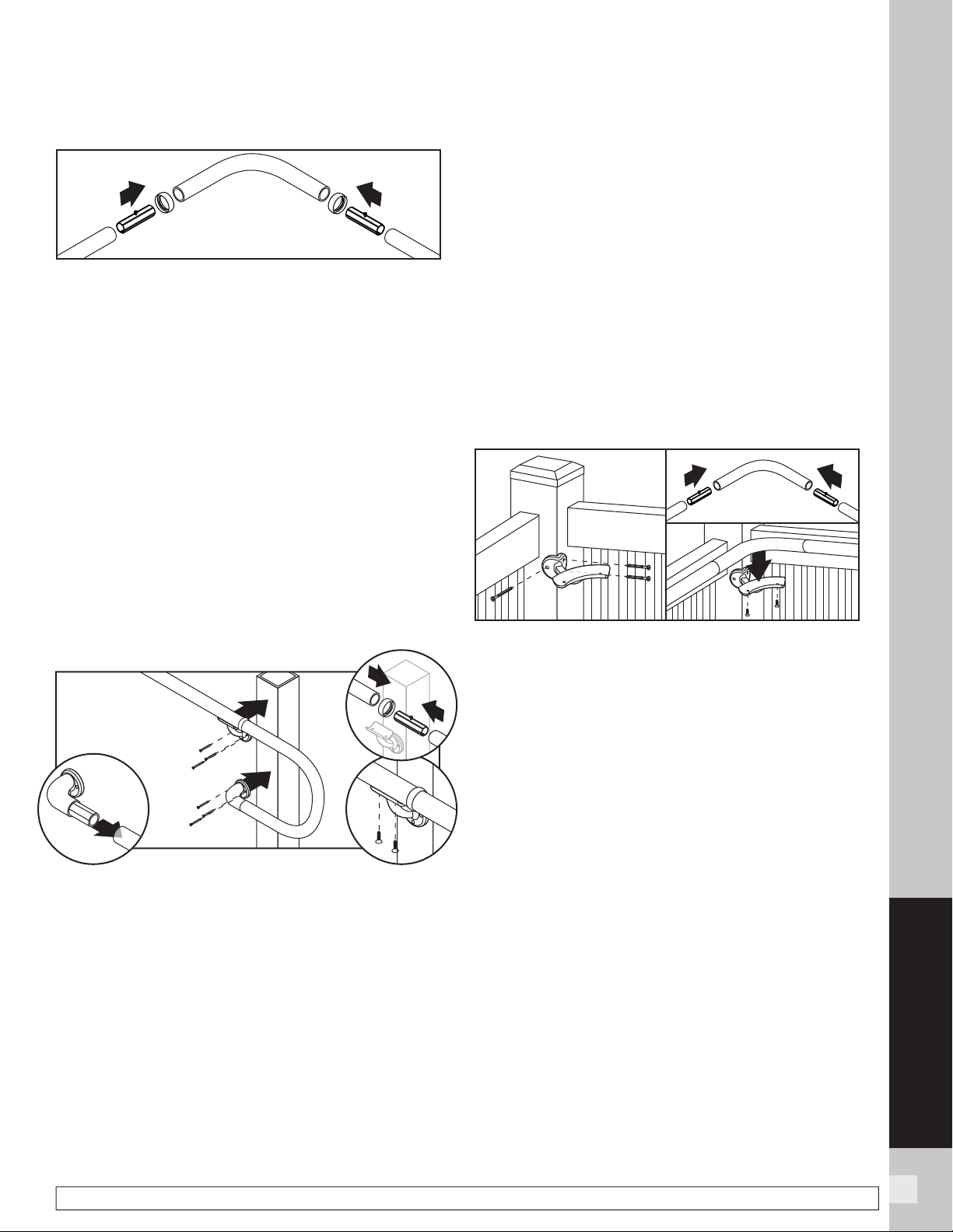
127
ADA RAILING
127127
Elbows (90°, 36°, 34°, 31°, 5° )
1. If required, cut railing to proper length based on
location of elbows and other components being
used.
2. If desired, collar ring can be used to hide seam of
elbow to rail. Slide this over rail BEFORE inserting rail
into elbow.
3. Slide internal connector into rail end until metal
spacer screw is touching either end of rail or the
collar, if this was used.
4. Slide appropriate angled elbow onto opposite end of
internal connector, until this is touching metal spacer
screw.
5. Remove metal spacer screw using #2 square head
screwdriver.
6. Push elbow further over internal connector until this
fi ts in the collar (if used) or fi ts tightly against rail.
7. Attach wall mount to post per previous instructions.
8. Attach rail to wall mount per previous instructions.
Handrail Return 180°
NOTE: Ramp application shown here. (For stair
applications appropriate angle elbow also required.)
1. If required, cut railing to proper length based on
location of elbow used as well and other components
being used.
2. If desired, collar ring can be used to hide seam of
handrail return to rail or elbow being used. Slide this
over rail BEFORE inserting rail into other component.
3. Ensure that all components are aligned to both wall
mount on post as well as location of elbow on rail
BEFORE attachment.
3. Slide internal connector into appropriate elbow being
until metal spacer screw is touching either end of
elbow or the collar, if this was used.
4. Attach wall return to lower end of handrail return
(longer side), ENSURING wall return is at proper
angle of alignment to post. (Wall return is designed
to have tight fi t into rail, thus location of attachment
is critical.)
5. Slide opposite end of handrail return onto internal
connector, until this is touching metal spacer screw.
6. Remove metal spacer screw using #2 square head
screwdriver.
7. Push handrail return further over internal connector
until this fi ts in the collar (if used) or fi ts tightly
against elbow.
8. Attach wall return to post per previous instructions.
9. Attach rail to wall mount per previous instructions.
10. Use end caps where required.
Corner Mount
1. Corner mount can ONLY BE USED ON METAL
POSTS and only for horizontal applications, such as
stair landings.
2. Pre-drill metal post and install corner post to metal
post using specifi c hardware provided (see chart on
previous page).
3. If desired, collar ring can be used to hide seam of
elbow to rail. Slide this over rail BEFORE inserting
rail into elbow (not shown in picture above).
3. Slide internal connector into rail end until metal
spacer screw is touching either end of rail or the
collar, if this was used.
4. Slide appropriate angled elbow onto opposite end
of internal connector, until this is touching metal
spacer screw.
5. Remove metal spacer screw using #2 square head
screwdriver.
6. Push elbow further over internal connector until this
fi ts in the collar (if used) or fi ts tightly against rail.
7. Install elbow to corner mount using specifi c
hardware provided (see chart on page 125).
HOW TO INSTALL TREX ALUMINUM ADA COMPLIANT HANDRAIL
NOTE: Construction methods are always improving. Please refer to www.trex.com for the most up-to-date installation requirements.
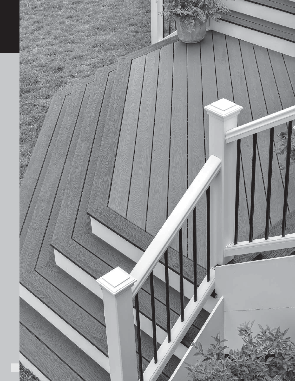
128
WARRANTIES
128
WARRANTIES
129
WARRANTIES
129129
For the term set forth below, Trex Company, Inc. (hereinafter
“Trex”) warrants to the original end-user purchaser (the
“Purchaser”) that Trex Transcend® decking, porch or fascia,
Trex Enhance® decking or fascia, Trex Select® decking or fascia
or Trex Universal Fascia, as the case may be (the “Product”) will
perform, under normal use and service conditions, as follows:
Term of Warranty: The term of this warranty shall begin on
the date of original purchase, and shall end (1) twenty-fi ve (25)
years thereafter for a residential application of the Product, and
(2) ten (10) years thereafter for a commercial application of the
Product.
Residential/Commercial Application: For purposes of this
warranty, a “residential application” shall refer to an installation
of the Product on an individual residence, and a “commercial
application” shall refer to any installation of the Product other
than on an individual residence.
Fade Resistance: The Product shall not fade in color from light
and weathering exposure as measured by color change of more
than 5 Delta E (CIE) units.
The Product is designed to resist fading. No material is fade
proof when exposed to years of UV exposure and the elements.
The Product is designed to resist fading, and will not in any event
fade by more than 5 Delta E (CIE) units.
Stain Resistance: The Product shall be resistant to permanent
staining resulting from spills of food and beverage items
including ketchup, mustard, salad oils, tea, wine, coffee, fruit
punch, barbeque sauce, grease, sodas and other food and
beverage related items that would typically be present on a
residential deck, or mold and mildew naturally occurring in the
environment, provided that such substances are removed from
the Product with soap and water or mild household cleaners
within one (1) week of exposure of the food or beverage to the
surface or fi rst appearance of the mold and mildew.
Notwithstanding the foregoing, Trex does not warrant that the
Product is stain-proof, and does not warrant stain resistance
resulting from spilled or otherwise applied food and beverage
substances which are not properly cleaned as provided above
within one (1) week of exposure. In addition, materials not covered
in the stain resistant warranty include abrasive compounds of
acidic or basic pH, paints or stains, strong solvents, metallic
rust or other abnormal deck use items, and non-food and non-
beverage substances, including but not limited to, biocides,
fungicides, plant food, or bactericides. Mold and mildew can
settle and grow on any outdoor surface, including this Product.
You should periodically clean your deck to remove dirt and pollen
that can feed mold and mildew. This warranty does not cover
mold and mildew which is not properly cleaned as provided
above within one (1) week of fi rst appearance.
Standard Trex Company Limited Warranty: This warranty is
in addition to the standard Trex Company Limited Warranty that
applies to all Trex products.
Transferability: With respect to a residential application, this
warranty may be transferred one (1) time, within the fi ve (5)
year period beginning from the date of original purchase by the
Purchaser, to a subsequent buyer of the property upon which
the Trex products were originally installed. With respect to a
commercial application, this warranty is freely transferable
to subsequent buyers of the property upon which the Trex
products were originally installed.
Exclusions from Warranty Coverage:
Exposure to Heat: Direct or indirect contact with extreme heat
sources (over 275 degrees) may cause fading and may damage
the surface of the Product, and any effects of such exposure are
expressly excluded from coverage under this warranty.
Surface Damage: Never use metal shovels or sharp-edged tools
to remove snow and ice on the surface of the Product. If the
surface of the Product is damaged or punctured, this warranty
will be voided.
Paint or Other Materials Applied to the Product: If paint or
other coating materials are applied to the Product, this warranty
will be voided.
Railing: This warranty does not cover Trex Transcend® or Trex
Select® railing components.
Other Exclusions: This warranty shall not cover any condition
attributable to: (1) improper installation of the Product and/or
failure to abide by Trex’s installation guidelines, including but
not limited to improper gapping; (2) use of the Product beyond
normal use or service conditions, or in an application not
recommended by Trex’s guidelines and local building codes; (3)
movement, distortion, collapse or settling of the ground or the
supporting structure on which the Product is installed; (4) any
act of God (such as fl ooding, hurricane, earthquake, lightning,
etc.); (5) improper handling, storage, abuse or neglect of the
Product by Purchaser, the transferee or third parties; (6) any
fading or staining not on the walking surface of the Product (i.e.,
the underside or the ends of the Product); or (7) ordinary wear
and tear.
Procedure for Making a Claim under this Warranty
In order to make a claim under this warranty, Purchaser must do
the following:
1. If the Purchaser is making a claim relating to the warranty on
stain resistance, Purchaser must do as follows:
TREX TRANSCEND
®
, TREX ENHANCE
®
,
TREX SELECT
®
AND TREX
®
UNIVERSAL FASCIA
LIMITED FADE AND STAIN WARRANTY
130
WARRANTIES
130
(a) Purchaser must try to clean the affected area of the deck by
using the cleaning procedures described above within one
(1) week of exposure of the food or beverage to the Product or
fi rst appearance of the mold and mildew.
(b) If the affected area remains reasonably unsatisfactory after
Purchaser has tried these cleaning procedures, then Purchaser
must have the affected area of the deck professionally cleaned
at Purchaser’s expense.
(c) If the affected area remains reasonably unsatisfactory after
the professional cleaning, Purchaser may make a claim under
this warranty, provided that such claim is made within thirty
(30) days after the professional cleaning.
2. To make a claim under this limited warranty, Purchaser, or the
transferee, shall send to Trex, within the warranty period
referred to above, a description and photographs of the affected
area of the Product, proof of purchase, and if the claim relates
to the warranty on stain resistance, proof of compliance with
paragraph 1 above, to the following address:
Trex Company, Inc.
Customer Relations
160 Exeter Drive
Winchester, VA 22603-8605
3. Upon confi rmation by an authorized Trex representative of a
valid claim hereunder, Trex’s sole responsibility shall be, at its
option, to either replace the affected item or refund the portion
of the purchase price paid by Purchaser for such affected item
(not including the cost of its initial installation). Replacement
material will be provided that is as close as possible in color,
design and quality as the replaced material, but Trex does not
guarantee an exact match as colors and design may change.
4. If a valid warranty claim hereunder is made during years
eleven (11) through twenty-fi ve (25) after the original purchase
for a residential application, recovery will be prorated. If Trex is
providing replacement materials, it may elect to replace
the percentage listed below of boards otherwise meeting the
requirements for a claim, or if it is refunding the purchase
price, it may elect to refund the percentage listed below of the
purchase price of boards otherwise meeting the requirements
for a claim.
5. TO THE FULLEST EXTENT PERMITTED UNDER THE LAW,
THIS WARRANTY SHALL NOT COVER AND TREX SHALL NOT
BE RESPONSIBLE FOR COSTS AND EXPENSES INCURRED
WITH RESPECT TO THE REMOVAL OF AFFECTED PRODUCT
OR THE INSTALLATION OF REPLACEMENT MATERIALS,
INCLUDING BUT NOT LIMITED TO LABOR AND FREIGHT.
No person or entity is authorized by Trex to make and Trex shall
not be bound by any statement or representation as to the
quality or performance of Trex products other than as contained
in this warranty. This warranty may not be altered or amended
except in a written instrument signed by Trex and Purchaser.
TO THE FULLEST EXTENT PERMITTED UNDER THE LAW,
UNDER NO CIRCUMSTANCES WILL TREX BE LIABLE
FOR INCIDENTAL OR CONSEQUENTIAL DAMAGES,
WHETHER SUCH DAMAGES ARE SOUGHT IN CONTRACT,
IN TORT (INCLUDING BUT NOT LIMITED TO NEGLIGENCE
AND STRICT LIABILITY) OR OTHERWISE, AND TREX’S
LIABILITY FOR NON-PERSONAL INJURY CLAIMS WITH
RESPECT TO PRODUCTS SHALL IN NO EVENT EXCEED THE
REPLACEMENT OF SUCH PRODUCTS OR REFUND OF THE
PURCHASE PRICE, AS DESCRIBED ABOVE.
Some States or Provinces do not allow the exclusion or limitation
of incidental or consequential damages, so the above limitation
or exclusion may not apply to you. This warranty gives you
specifi c legal rights, and you may also have other rights that
vary from State to State or Province to Province.
Copyright © 2016 Trex Company, Inc.
YEAR OF
WARRANTY CLAIM
PERCENTAGE
RECOVERY
11 80%
12 80%
13 80%
14 60%
15 60%
16 60%
17 40%
18 40%
19 40%
20 20%
21 20%
22 20%
23 10%
24 10%
25 10%
NOTE: Construction methods are always improving. Please refer to www.trex.com for the most up-to-date installation requirements.
TREX TRANSCEND
®
, TREX ENHANCE
®
,
TREX SELECT
®
AND TREX
®
UNIVERSAL FASCIA
LIMITED FADE AND STAIN WARRANTY/
CONTINUED

WARRANTIES
131131131
Trex Company, Inc. (hereinafter “Trex”) warrants to the original
purchaser (“Purchaser”) that, for the period of time set forth
in the following sentence, under normal use and service
conditions, Trex® products shall be free from material defects
in workmanship and materials, and shall not split, splinter, rot or
s u f f e r s t r u c t u r a l d a m a g e f ro m t e r m i te s o r f u n g a l d e c a y. T h e te r m
of such warranty shall be twenty-fi ve (25) years from the date of
original purchase for a residential application, and ten (10) years
from the date of original purchase for a commercial application.
If a defect occurs within the warranty period, Purchaser shall
notify Trex in writing and, upon confi rmation by an authorized
Trex representative of the defect, Trex’s sole responsibility shall
be, at its option, to either replace the defective item or refund
the portion of the purchase price paid by Purchaser for such
defective item (not including the cost of its initial installation).
Notwithstanding the foregoing, (a), the term of the
warranty for the LED lights and housing for Trex®
DeckLighting™ shall be seven (7) years, the term of
the warranty for the LED lights and housing for Trex®
LandscapeLighting™ shall be fi ve (5) years, and the term
of the warranty for the dimmer, timer and transformer
for both shall be three (3) years, in each case provided
that a Trex transformer is used (with no warranty on any
components if a Trex transformer is not used), and any
other parts or accessories shall not be warranted; (b)
with respect to hardware for the Trex Surroundings® gate
(gate frame, hinges and screws), the term of the warranty
shall be fi ve (5) years, (c) with respect to Trex Decorative
Balusters, the term of the warranty covering the paint
coating shall be ten (10) years, and shall be prorated in the
following manner: 100% replacement for the fi rst fi ve (5)
years; and 50% replacement for the next fi ve (5) years, and
(d) this warranty shall not apply to Trex Elevations® steel
deck framing, Trex Signature®/Reveal® aluminum railing
and TrexTrim™ (which each have separate warranties).
For purposes of this warranty, a “residential application” shall
refer to an installation of the Product on an individual residence,
and a “commercial application” shall refer to any installation of
the Product other than on an individual residence.
TO THE FULLEST EXTENT PERMITTED UNDER THE LAW,
THIS WARRANTY SHALL NOT COVER AND TREX SHALL NOT
BE RESPONSIBLE FOR COSTS AND EXPENSES INCURRED
WITH RESPECT TO THE REMOVAL OF DEFECTIVE TREX
PRODUCTS OR THE INSTALLATION OF REPLACEMENT
MATERIALS, INCLUDING BUT NOT LIMITED TO LABOR AND
FREIGHT.
With respect to a residential application, this warranty may
be transferred one (1) time, within the fi ve (5) year period
beginning from the date of original purchase by the Purchaser,
to a subsequent buyer of the property upon which the Trex
products were originally installed. With respect to a commercial
application, this warranty is freely transferable to subsequent
buyers of the property upon which the Trex products were
originally installed.
To make a claim under this limited warranty, Purchaser, or
the transferee, shall send to Trex, within the warranty period
referred to above, a description of the claimed defect and proof
of purchase, to the following address:
Trex Company, Inc.
Customer Relations
160 Exeter Drive
Winchester, VA 22603-8605
Trex does not warrant against and is not responsible for any
condition attributable to: (1) improper installation of Trex
products and/or failure to abide by Trex’s installation guidelines,
including but not limited to improper gapping; (2) use of Trex
products beyond normal use and service conditions, or in an
application not recommended by Trex’s guidelines and local
building codes; (3) movement, distortion, collapse or settling of
the ground or the supporting structure on which Trex products
are installed; (4) any act of God (such as fl ooding, hurricane,
earthquake, lightning, etc.), environmental condition (such as air
pollution, mold, mildew, etc.), staining from foreign substances
(such as dirt, grease, oil, etc.), or normal weathering (defi ned as
exposure to sunlight, weather and atmosphere which will cause
any colored surface to gradually fade, chalk, or accumulate dirt
or stains); (5) variations or changes in color of Trex products; (6)
improper handling, storage, abuse or neglect of Trex products
by Purchaser, the transferee or third parties; or (7) ordinary
wear and tear.
No person or entity is authorized by Trex to make and Trex shall
not be bound by any statement or representation as to the
quality or performance of Trex products other than as contained
in this warranty. This warranty may not be altered or amended
except in a written instrument signed by Trex and Purchaser.
TO THE FULLEST EXTENT PERMITTED UNDER THE LAW,
UNDER NO CIRCUMSTANCES WILL TREX BE LIABLE FOR
INCIDENTAL OR CONSEQUENTIAL DAMAGES, WHETHER
SUCH DAMAGES ARE SOUGHT IN CONTRACT, IN TORT
(INCLUDING BUT NOT LIMITED TO NEGLIGENCE AND
STRICT LIABILITY) OR OTHERWISE, AND TREX’S LIABILITY
FOR NON-PERSONAL INJURY CLAIMS WITH RESPECT TO
DEFECTIVE PRODUCTS SHALL IN NO EVENT EXCEED THE
REPLACEMENT OF SUCH PRODUCTS OR REFUND OF THE
PURCHASE PRICE, AS DESCRIBED ABOVE.
Some States or Provinces do not allow the exclusion or limitation
of incidental or consequential damages, so the above limitation
or exclusion may not apply to you. This warranty gives you
specifi c legal rights, and you may also have other rights that
vary from State to State or Province to Province.
Copyright © 2016 Trex Company, Inc.
TREX LIMITED WARRANTY

132
WARRANTIES
132
NOTE: Construction methods are always improving. Please refer to www.trex.com for the most up-to-date installation requirements.
Trex Company, Inc. (hereinafter “Trex”) warrants to the original
purchaser (“Purchaser”) that, under normal use and service
conditions, Trex Signature®/Reveal® Railing (the “Product”)
shall, for a period of twenty-fi ve (25) years from the date of
original purchase, be free from material defects in workmanship
and materials. If a defect occurs within the warranty period,
Purchaser shall notify Trex in writing and, upon confi rmation
by an authorized Trex representative of the defect, Trex’s
sole responsibility shall be, at its option, to either replace the
defective Product or refund the portion of the purchase price
paid by Purchaser for such defective Product (not including the
cost of its initial installation).
With respect to installations where the atmosphere is infl uenced
by a body of salt water (or other contaminant conditions), failure
to adhere to the cleaning guidelines available at www.trex.com
will void this warranty with respect to any condition resulting
from such failure.
TO THE FULLEST EXTENT PERMITTED UNDER THE LAW,
THIS WARRANTY SHALL NOT COVER AND TREX SHALL NOT
BE RESPONSIBLE FOR COSTS AND EXPENSES INCURRED
WITH RESPECT TO THE REMOVAL OF DEFECTIVE PRODUCT
OR THE INSTALLATION OF REPLACEMENT MATERIALS,
INCLUDING BUT NOT LIMITED TO LABOR AND FREIGHT.
This warranty may be transferred one (1) time, within the fi ve (5)
year period beginning from the date of original purchase by the
Purchaser, to a subsequent buyer of the property upon which
the Product was originally installed.
To make a claim under this limited warranty, Purchaser, or
the transferee, shall send to Trex, within the warranty period
referred to above, a description of the claimed defect and proof
of purchase, to the following address:
Trex Company, Inc.
Customer Relations
160 Exeter Drive
Winchester, VA 22603-8605
Trex does not warrant against and is not responsible for, and
no implied warranty shall be deemed to cover, any condition
attributable to: (1) improper installation of the Product; (2) use
of the Product beyond normal use and service conditions, or in
an application not recommended by Trex’s guidelines and local
building codes; (3) movement, distortion, collapse or settling
of the ground or the supporting structure on which the Product
is installed; (4) damages attributable to fi re, violent storms,
earthquake or other Acts of God, accidents, vandalism, or
other casualties, impact of objects, or exposure to atmospheric
pollutants or conditions other than natural weather processes,
(5) improper handling, storage, abuse or neglect of the Product
by Purchaser, the transferee or third parties; or (6) ordinary
wear and tear.
No person or entity is authorized by Trex to make and Trex shall
not be bound by any statement or representation as to the
quality or performance of Trex products other than as contained
in this warranty. This warranty may not be altered or amended
except in a written instrument signed by Trex and Purchaser.
TO THE FULLEST EXTENT PERMITTED UNDER THE LAW,
UNDER NO CIRCUMSTANCES WILL TREX BE LIABLE FOR
INCIDENTAL OR CONSEQUENTIAL DAMAGES, WHETHER
SUCH DAMAGES ARE SOUGHT IN CONTRACT, IN TORT
(INCLUDING BUT NOT LIMITED TO NEGLIGENCE AND
STRICT LIABILITY) OR OTHERWISE, AND TREX’S LIABILITY
FOR NON-PERSONAL INJURY CLAIMS WITH RESPECT TO
DEFECTIVE PRODUCTS SHALL IN NO EVENT EXCEED THE
REPLACEMENT OF SUCH PRODUCTS OR REFUND OF THE
PURCHASE PRICE, AS DESCRIBED ABOVE.
Some States or Provinces do not allow the exclusion or limitation
of incidental or consequential damages, so the above limitation
or exclusion may not apply to you. This warranty gives you
specifi c legal rights, and you may also have other rights that
vary from State to State or Province to Province.
Copyright © 2016 Trex Company, Inc.
TREX SIGNATURE
®
/REVEAL
®
RAILING
LIMITED WARRANTY

133133133
NOTES

134134
NOTE: Construction methods are always improving. Please refer to www.trex.com for the most up-to-date installation requirements.
NOTES
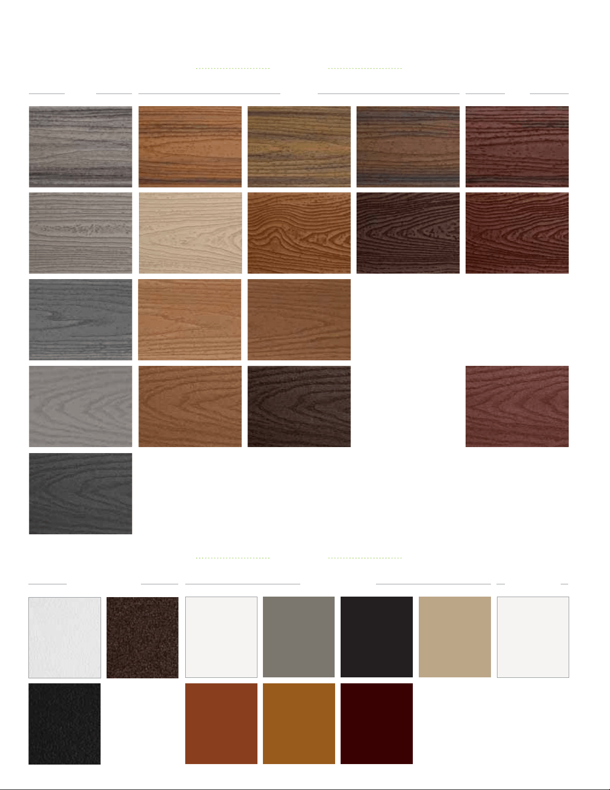
DECKING & RAILING COLOR PALETTE
Winchester Grey
Select
®
Beach Dune
Enhance
®
Saddle
Enhance
®
Fire Pit
Transcend
®
-
Classic Earth Tone
Vintage Lantern
Transcend
®
-
Classic Earth Tone
Island Mist
Transcend
®
-
Premium Tropical
Greys
RedsBrowns
Tiki Torch
Transcend
®
-
Premium Tropical
Havana Gold
Transcend
®
-
Premium Tropical
Spiced Rum
Transcend
®
-
Premium Tropical
Lava Rock
Transcend
®
-
Premium Tropical
Gravel Path
Transcend
®
-
Classic Earth Tone
Rope Swing
Transcend
®
-
Classic Earth Tone
Tree House
Transcend
®
-
Classic Earth Tone
Clam Shell
Enhance
®
Pebble Grey
Select
®
Saddle
Select
®
Woodland Brown
Select
®
Madeira
Select
®
Rope Swing
Tree HouseFire Pit Vintage Lantern
Charcoal Black
Gravel Path
Classic White
Charcoal Black
Aluminum
Bronze
Aluminum
Classic White
Aluminum
Classic White
Trex Transcend
®
Trex Signature
®
Trex Select
®
RAILING
DECKING
135
XKLTINGD20170117
FIND US ON
Visit trex.com or call 1-800-BUY-TREX
© 201. Trex Company, Inc. All rights reserved. Trex
®
, the Trex logo, Trex Transcend
®
, Trex Enhance
®
, Trex Select
®
, Trex Hideaway
®
, Trex Elevations
®
,
Trex
®
RainEscape
®
, Trex
®
Outdoor Lighting
™
, Trex Blade
™
, Trex
®
Landscape Lighting
™
, Trex
®
OutdoorStorage
™
, Trex Signature
®
, Trex
®
Spiral Stairs
™
, Trex
®
Deck Lighting
™
,
Trex Escapes
®
, Trex
®
Pergola
™
and TrexPro
®
are either federally registered trademarks, trademarks or trade dress of Trex Company, Inc., Winchester, Virginia.
FPO
BACK
decking: Transcend in Lava Rock & Tiki Torch
railing: Signature in Charcoal Black