Loading ...
Loading ...
Loading ...
Driving
Hitching and connecting the trailer
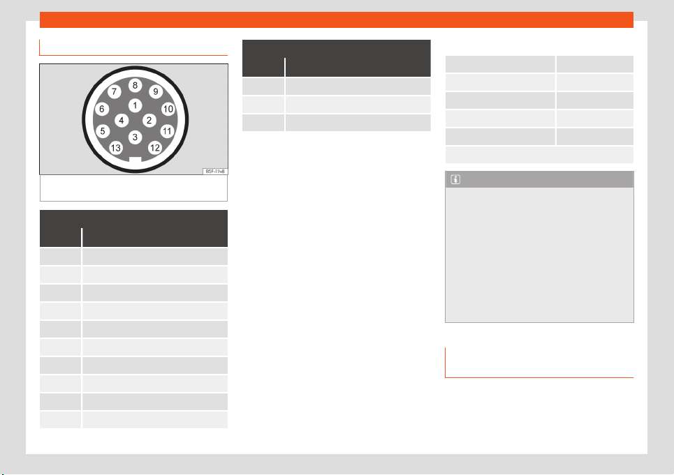
Fig. 302 Diagram: assignment of the pins of
the trailer
's electrical socket.
Key of the Schematic diagram
›››
Fig. 302:
Pin Meaning
1 Left turn signal
2 Rear fog light
3 Earth, pins 1, 2, 4 to 8
4 Right turn signal
5 Rear light, right
6 Brake lights
7 Rear light, left
8 Reverse lights
9 Permanent live
10 Cable without positive charge
Key of the Schematic diagram
›››
Fig. 302:
Pin Meaning
11 Earth, pin 10
12 Unassigned
13 Earth, pin 9
Electrical socket for trailer
The vehicle is fitted with a 13-pole power
socket for the electrical connection between
the trailer and the vehicle. If the system de-
tects that a trailer has been connected elec-
trically, the electrical equipment on the trailer
will receive voltage through this connection.
Pin 9 has a permanent live. This powers, for
example, the trailer's interior lighting. Pin 10 is
only powered when the engine is running. The
charge wire (pin 10) charges, for example, a
caravan battery.
Pin 9 and 10 should not be connected to
each other to avoid discharging or damaging
the vehicle's battery.
The earth wires, pin 3, pin 11 and pin 13, should
never be connected to each other to avoid
overloading the electrical system.
If the trailer has a 7-contact connector, you
will need to use an adapter cable. In this case
the function corresponding to pin 10 will not
be available.
Trailer maximum electricity consumption
Brake lights (total) 84 Watts
Turn signal, on each side 42 Watts
Side lights (total) 100 Watts
Rear lights (total) 42 Watts
Rear fog light 42 Watts
Never exceed the values indicated!
Note
●
If the rear lights of the trail
er are not cor-
rectly connected, the vehicle electronics
may be damaged.
●
If the trailer absorbs excessive electric
current, the vehicle electronics may be
damaged.
●
Never connect the trailer's electric sys-
tem directly to the electrical connections
of the tail lights or any other power sour-
ces. Only use the connections intended for
providing electric current to the trailer.
Ball coupling of towing bracket de-
vice*
The ball coupling is provided with instructions
on fitting and r
emo
ving the ball coupling of
the t
owing bracket.
308
Loading ...
Loading ...
Loading ...