Loading ...
Loading ...
Loading ...
Driving
Thus adjusted, the detachable ball is ready
f
or inst
all
ation.
CAUTION
The key cannot be removed or turned in the
standby position.
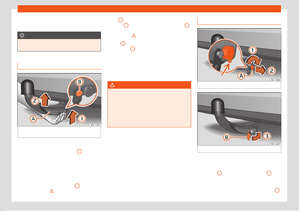
Fitting the tow hitch Step 1
Fig. 295 Fitting the detachable ball / Release
bolt in the depl
oyed position.
Fitting the detachable ball
●
Remove the hook housing cap
4
›››
Fig. 291 do
wnw
ar
ds.
●
Set the detachable ball to its standby posi-
tion
›››
page 303.
●
Grip the detachable ball from below
›››
Fig. 295 and insert it into the hook housing
following the direction of arrow
1
until it en-
gages audibly
›
›
›
.
Lever
A
turns aut
omatically in the direction
of arr
o
w
2
upwards, and the release bolt
B
moves outwards (the red and green part will
be visibl
e)
›
›
›
.
If l
e
v
er
A
does not turn automatically or the
r
el
ease bolt
B
does not come out, the de-
t
achabl
e ball shoul
d be removed by turning
the lever as far as possible downwards from
the housing cavity, and the detachable ball's
support surfaces and the cavity should then
be cleaned.
WARNING
●
When attaching the detachabl
e ball,
keep your hands well away from the reach
of the lever's rotation. There is a risk of in-
juring your fingers!
●
Never try to pull the lever upwards by
force to turn the key. The detachable ball
would not be secured properly!
Fitting the tow hitch Step 2
Fig. 296
Locking the lock.
Fig. 297
Placing the cover over the lock.
Do not omit this first step
›
›
›
page 304, Fit-
ting the tow hitch Step 1!
●
Turn key
A
in the direction of arrow
1
until
the part of the k
ey with the hol
es r
eaches the
bottom position
›››
Fig. 296.
●
Remove the key in the direction of arrow
2
.
304
Loading ...
Loading ...
Loading ...