Loading ...
Loading ...
Loading ...
Power Analyzers
Appendix A
81
load voltage e
L
is 250 V or more, the effect on the measurement accuracy is less than 0.1 %. In
summary, when measuring low voltage and large current, it is recommended to use the wiring method
of the figure above; when measuring high voltage and small current, it is recommended to use the
wiring method of the figure below.
Effects of Leakage Capacitance
Each measurement channel of the Analyzer is isolated from each other. However, these isolated
channels still have a leakage capacitance C
s
relative to the earth, which consists of the distributed
capacitance of the instrument itself, the isolation capacitance of the power adapter, and the anti-
interference capacitance inside the instrument. In general, the test object of the Analyzer has a higher
voltage relative to the earth, and we call this voltage common mode voltage V
com
. The common mode
voltage can generate a current i
cs
through the leakage capacitance C
s
. This current i
cs
will have a
certain impact on the measurement results of the Analyzer.
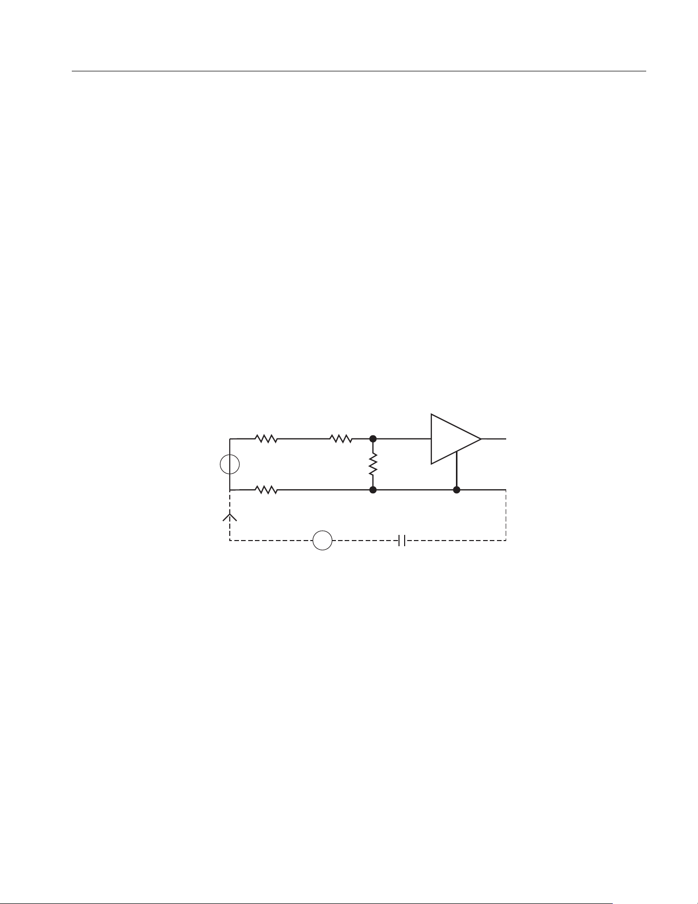
As shown in
Figure A3, during voltage measurement, the current i
cs
is coupled to the measurement
circuit through R
s+
, R
s-
and R
in
. R
s+
and R
s-
are internal resistances of the power supply under
measurement and R
in
is the test internal resistance of the power analyzer. The effect on the
measurement voltage is: . Because R
in
is larger, internal resistance of
the power supply under measurement R
s-
has the main impact. R
s-
is connected to the common
terminal (black terminal) of the measurement circuit.
Figure A3. Effects of Leakage Current on Voltage Measurement
During current measurement, the current i
cs
flows through the test resistance R
shunt
, and the internal
resistance of the test resistance and the common terminal of the measurement circuit R
s-
and forms a
voltage, that is coupled into the measurement circuit. The effect on the measurement
current: , the voltage drop of i
cs
in R
Shunt
and internal resistance R
s -
can cause measurement errors.
∆Ui
cs
R
S-
//(R
S+
R
in
)+[]=
RinRs+
Rs-
Cs
Ics
U
2M Ohm
∆U= Ics[Rs-//(Rs+ + Rin)]
Vcom
∆Ii
cs
R
Shunt
R
S-
+()R
Shunt
⁄[]=
1.888.610.7664 sales@GlobalTestSupply.com
Fluke-Direct.com
Loading ...