Loading ...
Loading ...
Loading ...
NORMA 6003/NORMA 6003+/NORMA 6004/NORMA 6004+
Users Manual
80
How to Make More Accurate Measurements
Measurement Error Caused by the Channel Resistance
By wiring a circuit to match the load, you can minimize the effects of power loss on measurement
accuracy. The wiring of the source and load is discussed in this section.
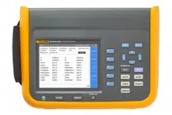
Figure A1. Connect the Voltage Measurement near the load
Connect the voltage measurement circuit near the load (as shown in
Figure A1). The current
measurement circuit measures the sum of i
Connect the Voltage Measurement near the loadL
and i
V
. i
L
(desired
current) is the current flowing through the load of the circuit under measurement, and i
V
(error current)
is the current flowing through the voltage measurement circuit. Because the current flowing through the
circuit under measurement is i
L
, only i
V
reduces measurement accuracy. The input resistance of the
voltage measurement circuit of the Analyzer is approximately 2 MΩ. If the input voltage is 1000 V, i
V
is
approximately 0.5 mA (1000 V/2 MΩ). Only when the load current i
L
is 0.5 A or more, the effect of i
V
on
the measurement accuracy is 0.1% or less.
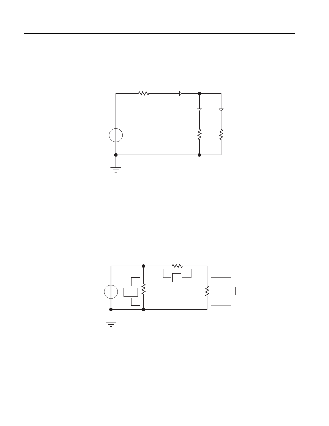
Figure A2. Connect the Voltage Measurement near the source
Connect the voltage measurement circuit near the source (as shown in
Figure A2). The voltage
measurement circuit measures the sum of e
L
and e
I
. e
L
(desired voltage) is the load voltage, and e
I
(error voltage) is the voltage drop across the current measurement circuit. The input resistance of the
current measurement circuit of the Analyzer, I Rin is approximately 0.025 Ω. If the input current is 10 A,
the effect of e
I
on the measurement accuracy is approximately 0.25 V (10 A×0.025 Ω). Only when the
I Rin=0.025Ω
U Rin=2MΩ
iv+iL
iv iL
Load
Source
+
I Rin=0.025Ω
U Rin=2MΩ
Load
Source
+
e
L
e
i
e
L
e
i
+
1.888.610.7664 sales@GlobalTestSupply.com
Fluke-Direct.com
Loading ...
Loading ...