
Loading ...
Loading ...
Loading ...
PERIODIC MAINTENANCE 2-19
Periodic Maintenance Procedures
•
Back out the same number of turns counted when first
turned in. This is to set the screw to its original position.
NOTE
○
A throttle body has different “turns out” of the bypass
screw for each individual unit. On setting the bypass
screw, use the “turns out” determined during disassem-
bly.
•
Repeat the same procedure for other bypass screws.
•
Repeat the synchronization.
If the vacuums are correct, check the output voltage of
the main throttle sensor (see Main Throttle Sensor Output
Voltage Inspection in the Fuel System (DFI) chapter).
Special Tool - Throttle Sensor Setting Adapter: 57001
-1538
Main Throttle Sensor Output Voltage
Connections to Adapter:
Digital Meter (+) → R (sensor Y/W) lead
Digital Meter (–) → BK (sensor G) lead
Standard: DC 1.02
∼ 1.06 V at idle throttle opening
If the output voltage is out of the standard, check the in-
put voltage of the main throttle sensor (see Main Throttle
Sensor Input Voltage Inspection in the Fuel System (DFI)
chapter).
•
Remove the vacuum gauge hoses and install the rubber
caps on the original position.
•
For CAL, SEA-B1 and TH Models, install the vacuum
hoses.
Run the vacuum hoses according to Cable, Wire, and
Hose Routing section in the Appendix chapter.
•
Install the removed parts (see appropriate chapters).
Fuel System
Fuel Hose Inspection (fuel leak, damage, installation
condition)
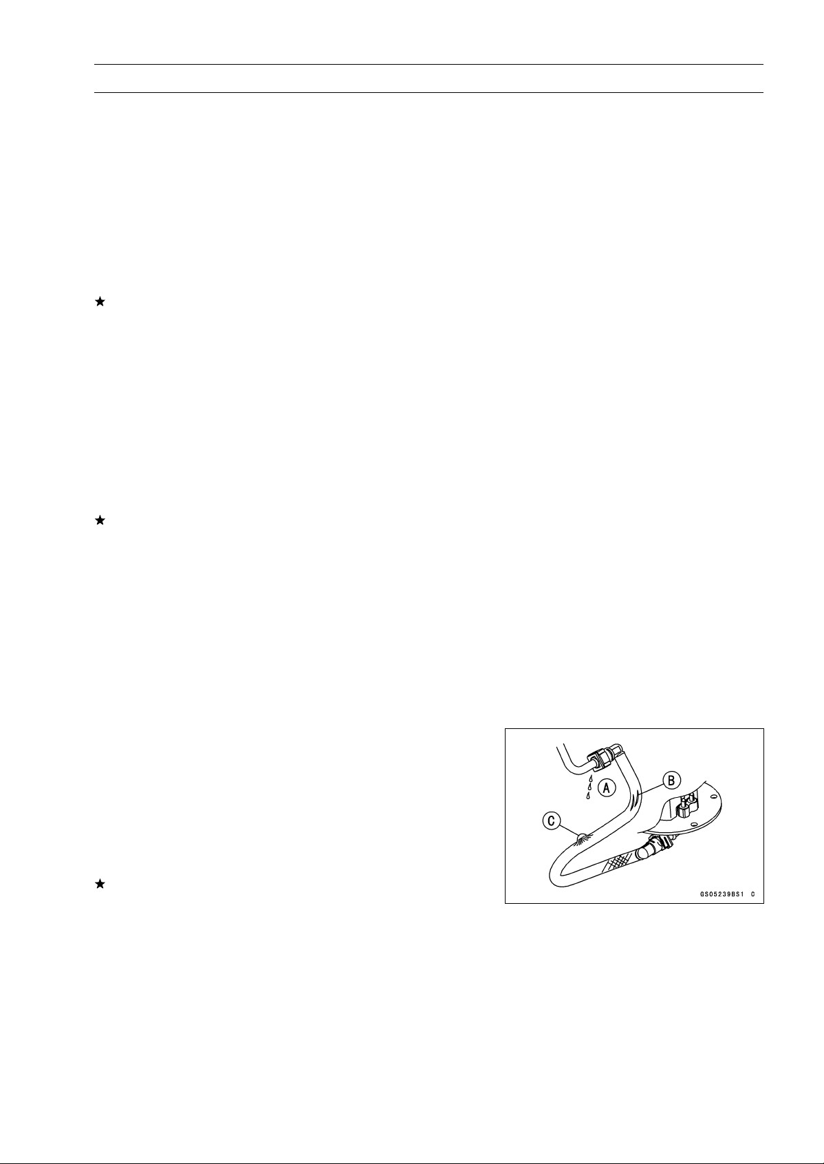
If the motorcycle is not properly handled, the high pres-
sure inside the fuel line can cause fuel to leak [A] or the
hose to burst. Remove the fuel tank (see Fuel Tank Re-
moval in the Fuel System (DFI) chapter) and check the
fuel hose.
Replace the fuel hose if any fraying, cracks [B] or bulges
[C] are noticed.
Loading ...
Loading ...
Loading ...