
Loading ...
Loading ...
Loading ...
3-58 FUEL SYSTEM (DFI)
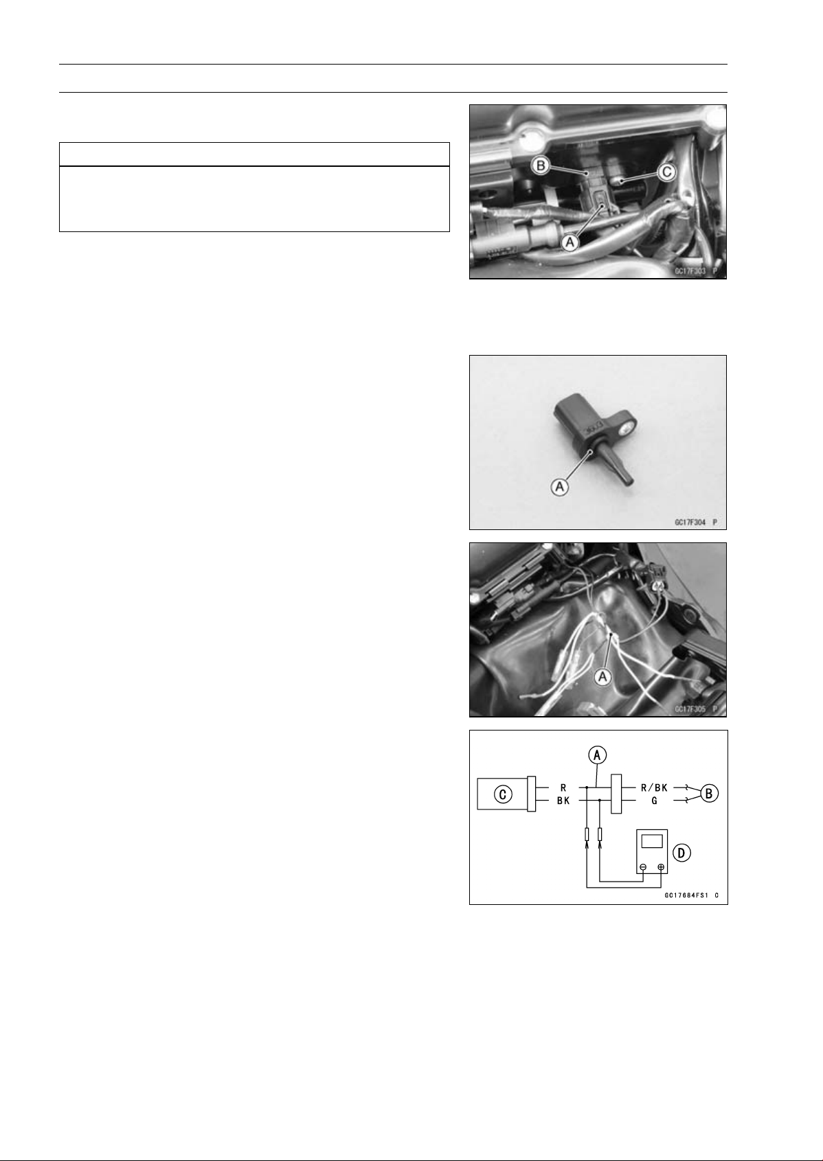
Intake Air Temperature Sensor (Service Code 13)
Intake Air Temperature Sensor Removal/Instal-
lation
NOTICE
Never drop the intake air temperature sensor espe-
cially on a hard surface. Such a shock to the sensor
can damage it.
•
Remove the fuel tank (see Fuel Tank Removal).
•
Disconnect the connector [A] from the intake air temper-
ature sensor [B].
•
Remove:
Intake Air Temperature Sensor Screw [C]
Intake Air Temperature Sensor
•
Be sure to install the O-ring [A].
•
Install the intake air temperature sensor.
•
Tighten:
Torque - Intake Air Temperature Sensor Screw: 1.2 N·m
(0.12 kgf·m, 11 in·lb)
•
Connect the intake air temperature sensor lead connec-
tor.
•
Install the fuel tank (see Fuel Tank Installation).
Intake Air Temperature Sensor Output Voltage
Inspection
NOTE
○
Be sure the battery is fully charged.
•
Turn the ignition switch off.
•
Remove the fuel tank (see Fuel Tank Removal).
•
Disconnect the intake air temperature sensor connector
and connect the measuring adapter [A] between these
connectors as shown.
Main Harness [B]
Intake Air Temperature Sensor [C]
Special Tool - Measuring Adapter: 57001-1700
•
Connect a digital meter [D] to the measuring adapter
leads.
Intake Air Temperature Sensor Output Voltage
Connections to Adapter:
Digital Meter (+) → R (sensor R/BK) lead
Digital Meter (–) → BK (sensor G) lead
•
Measure the output voltage with the engine stopped and
the connector joined.
•
Turn the ignition switch on.
Output Voltage
Standard: About DC 2.25
∼ 2.50 V at 20°C (68°F)
NOTE
○
The output voltage changes according to the intake air
temperature.
Loading ...
Loading ...
Loading ...