Loading ...
Loading ...
Loading ...
Chapter 5 To Trigger the Oscilloscope RIGOL
MSO7000/DS7000 User's Guide 5-17
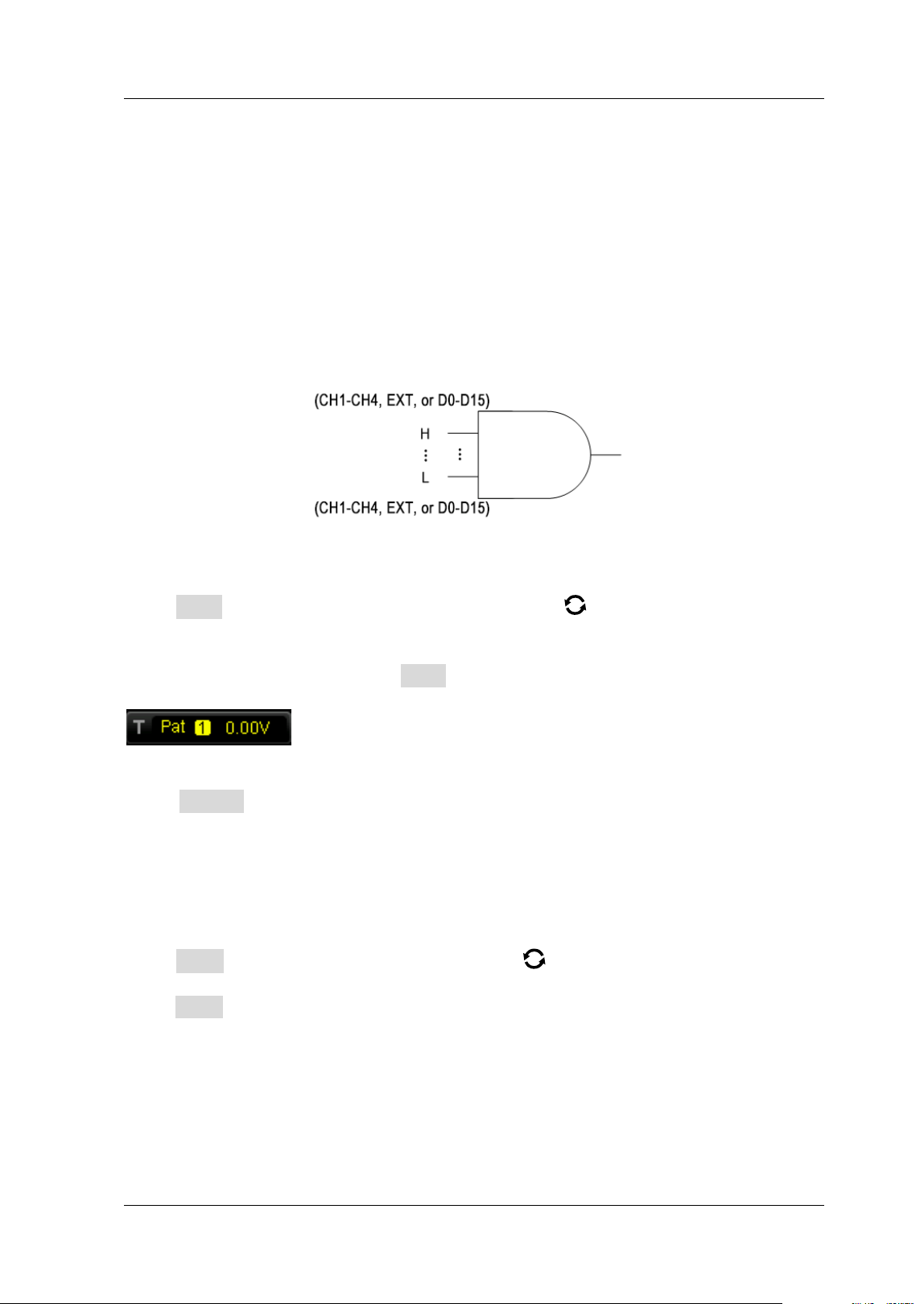
Pattern Trigger
Identifies a trigger condition by searching for a specified pattern. This pattern is a
logical "AND" combination of channels. Each channel can be set to H (high), L (low),
or X (don't care). A rising or falling edge (you can only specify a single edge) can be
specified for one channel included in the pattern. When an edge is specified, the
oscilloscope will trigger at the edge specified if the pattern set for the other channels
are true (namely the actual pattern of the channel is the same as the preset pattern).
If no edge is specified, the oscilloscope will trigger on the last edge that makes the
pattern true. If all the channels in the pattern are set to "X", the oscilloscope will not
trigger.
Figure 5-5 Pattern Trigger
Trigger Type:
Press Type, and then rotate the multifunction knob to select "Pattern". Press
down the knob to select the trigger type. Then, the current trigger setting
information is displayed at the upper-right corner of the screen, as shown in the
figure below. You can also press Type continuously to select the trigger type or
enable the touch screen to tap the desired trigger type and select it.
Source Selection:
Press Source to open the signal source list and select CH1-CH4 or D0-D15. For
details, refer to descriptions in "Trigger Source". The current trigger source is
displayed at the upper-right corner of the screen.
Note: Only when we select the channel (that has been input with signals) as the
trigger source, can we obtain a stable trigger.
Pattern Setting:
Press Code, and rotate the multifunction knob to select the pattern of the
currently selected channel. Press down the knob to select the pattern. You can also
press Code continuously to select the pattern or enable the touch screen to select it.
The available patterns include the following five types:
H: sets the pattern of the channel selected to "1", i.g. the voltage level is higher
than the trigger level/threshold level of the channel.
L: sets the pattern of the channel selected to "0", i.g. the voltage level is lower
than the trigger level/threshold level of the channel.
X: sets the pattern of the channel selected to "X", i.g. this channel is not used as
Loading ...
Loading ...
Loading ...