Loading ...
Loading ...
Loading ...
MID-STATIC DUCTED TECHNICAL OVERVIEW
G-4
ENGLISH
Components
This control board has control over the fan louver movement, manual fan blower control, indoor coil temperature and indoor air
temperature sensing functions. All operational decisions are controlled by the OUTDOOR UNIT ECU.
The control board has a replaceable 5A 250V fuse that protects against excessive current. If power is present at the board but
the board does not work, check for continuity through the fuse. Replace if the fuse is open.
The indoor unit temperature sensors are connected at Plug CN-13. When testing the calibration of these sensors, the wires can
be released from the plug by pressing on the tension tab on the side of the plug.
There 3 motors that control the directional movement of the accessory louver. The motor connects to the circuit board at Plug
CN-14, CN-15 and CN-16. The motors are located in the louver assembly.
The blower motor is connected to the circuit board at plug CN-6.
The Indoor Unit Circuit Board communicates with the outdoor unit ECU
via a connection at Terminal Block screw 3. The data pulse that sends the
communication information can be measured with a voltmeter placed to DCV
range. From the ground connection at the Terminal Block to the Number 3
screw connection, the voltage should pulse up and down when data is being
transmitted.
Line voltage to power the indoor unit comes in on Terminal Block connections
1 and 2. Power connects from these terminal connections to CH- 1 and CH-2 on
the circuit board. If the board does not respond to commands and has no display,
check for line voltage at these connections. When power is present at the indoor
board, the wired controller will be energized.
The connections on the indoor board are shown here in the schematic drawing.
Outdoor unit
3
2
Power
Wiring
1
)
(
N
)
(L
)
(
C
3
2
1
)
(
N
)
(
L
)
(
C
Indoor uni
t
3wire 14AWG
Control Wiring
Outdoor unit
3
2
Power
Wiring
1
)
(
N
)
(L
)
(
C
2
1
)
(
N
)
(
L
Indoor uni
t
3wire 14AWG
Control Wiring
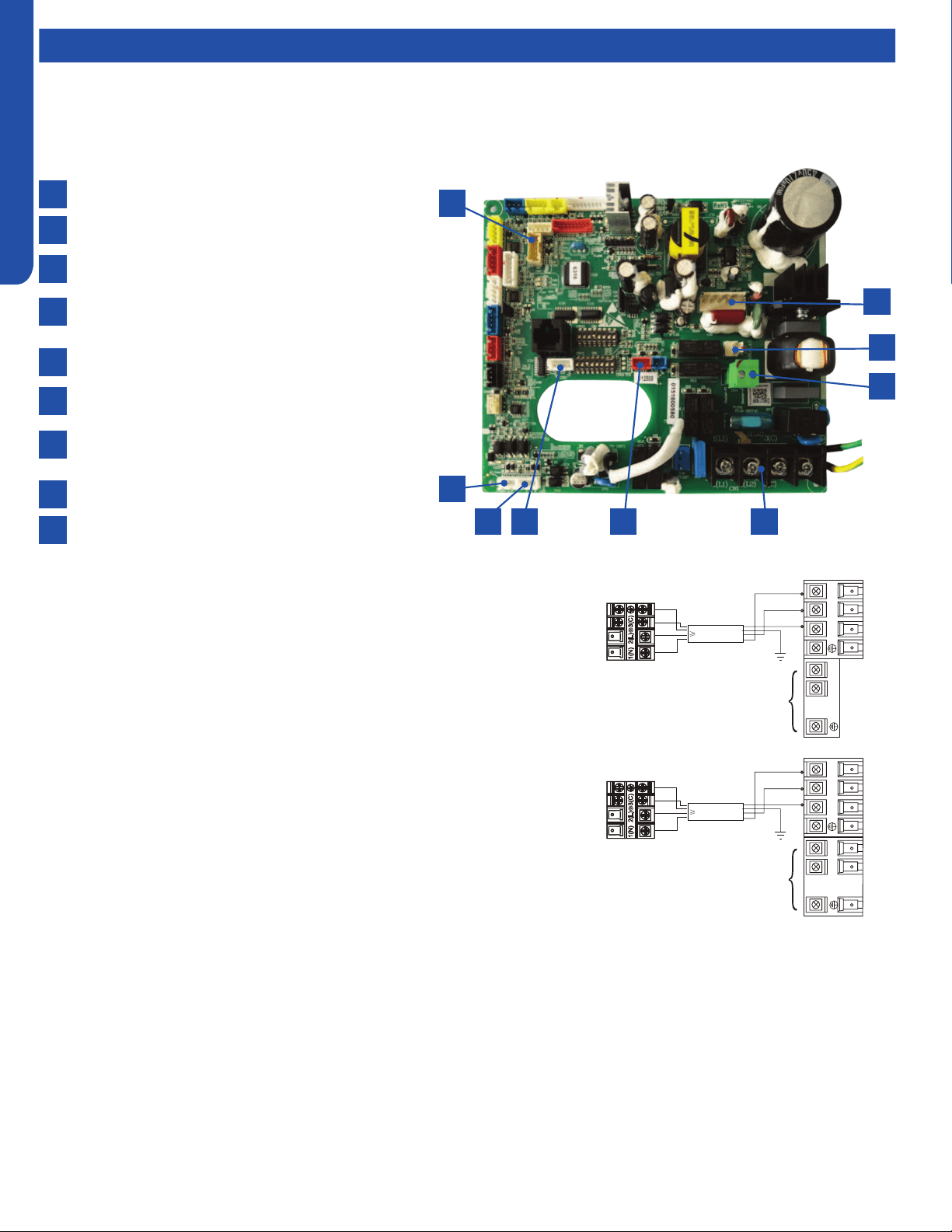
Indoor Unit Circuit Board
The indoor unit circuit board controls the switching functions of the indoor unit. All control decisions are made by the outdoor
unit ECU. The indoor board has some limited diagnostic capability which will be covered in this manual.
9
8
7
6
1
2
3
4
5
CN17-GEA3 wi module socket
CN6-DC fan motor socket
CN10-Fresh air link/E.A.O socket
CN-4-Frelay for auxiliary heater link (Dry contact,rating-
230VAC ,3A)
CN1- Power terminal block
CN19-Float switch socket
CN3-Temperature sensor socket (Tr:ROOM SENSOR,
Tp:PIPE SENSOR)
CN22-1-Wired controller socket2
CN22-Wired controller socket1
6 578
2
1
9
3
4
Loading ...
Loading ...
Loading ...