Loading ...
Loading ...
Loading ...
OUTDOOR TECHNICAL OVERVIEW
B-17
ENGLISH
Testing
4-Way Valve
The 4-way valve will control the direction of hot gas discharge via
an internal slide assembly. The valve has a line voltage solenoid
that is energized in heat mode. The solenoid will direct the internal
slide to send the hot gas to the indoor coil. During cooling mode
de-energized operation, the internal slide will direct compressor
hot gas to the outdoor coil.
4-way valves may have a failure of the electrical solenoid that
prevents the valve from shifting, or they may become stuck due to
debris lodging inside the valve body. If the valve fails to direct the
hot gas in the proper direction, temperature sensors within the
outdoor unit will detect the problem and generate an error code.
If the valve fails to shift the hot gas to the proper coil, or it only
partially shifts, perform the following:
1. Check for correct refrigerant charge, and that all other operating parameters have been met.
2. In the heating mode, the solenoid will shift after a short time delay. Check for line voltage to the solenoid coil.
3. If the valve has voltage but fails to shift the hot gas to the indoor coil, shut the system down and unplug the 4-way valve from
the PCB plug.
4. Use an ohmmeter to check continuity through the solenoid coil. The coil resistance should be 2.1k Ohms. If a winding shows
open or shorted, the solenoid coil will have to be replaced.
5. If the coil resistance is within the tolerance, use a magnet along the valve body to determine the location of the piston. If one
end of the piston is against the end of the valve body, it is stuck and the valve must be replaced.
6. Partial shifting of the valve can be detected by measuring the temperature of the suction gas where it enters the reversing
valve and then comparing that temperature to the temperature of the suction gas exiting the 4-way valve. There should be
no more than a 13°F dierence. Excessive temperature rise through the suction gas path is an indication of a stuck piston. If
the piston will not become free by switching from heating to cooling several times, a slight tapping on the valve body, or by
using a powerful magnet, the valve will require replacement.
12VDC
EEV Terminals
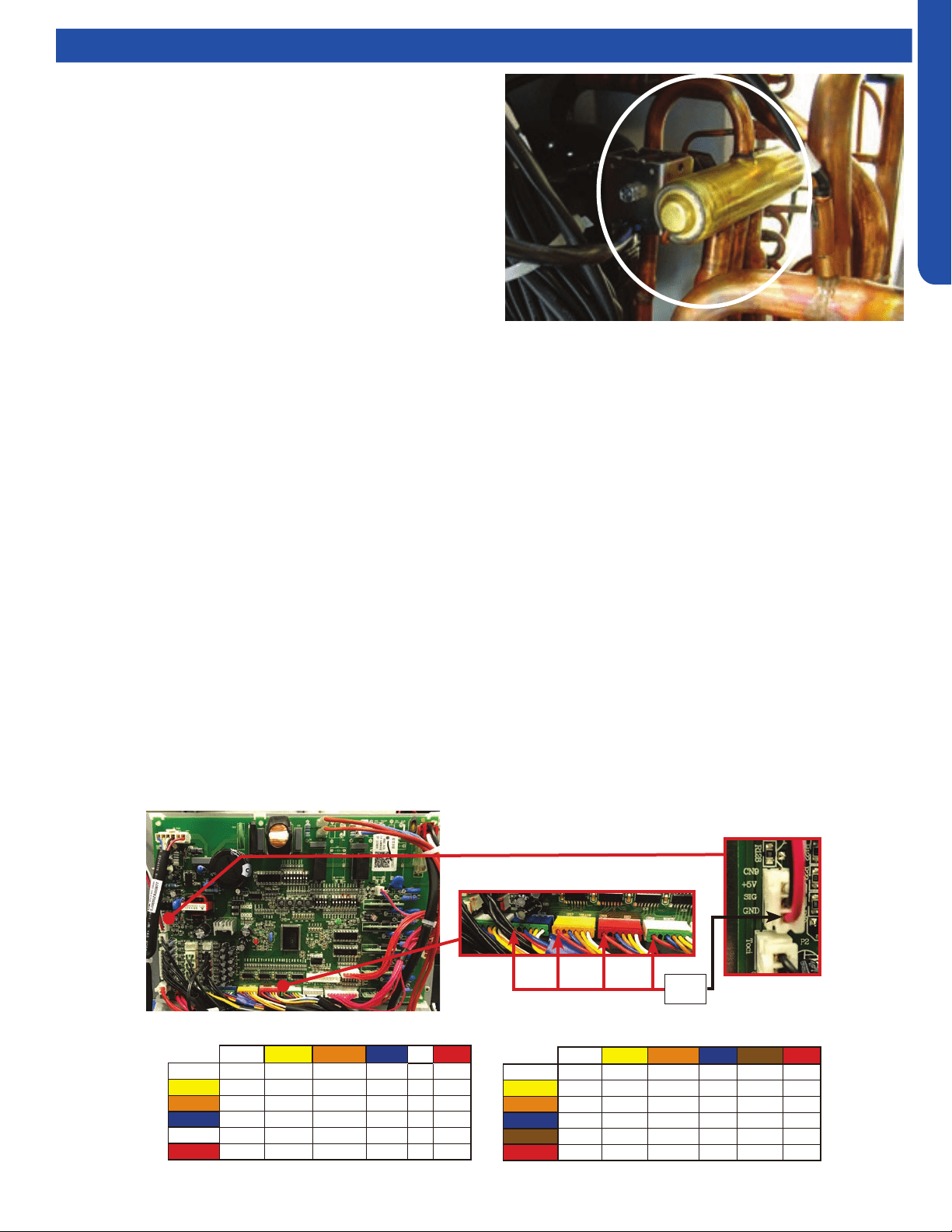
Electronic Expansion Valve (EEV)
EEV (6-pin, 6 wire)
White Yellow Orange
Blue Brown Red
White - OL 92 Ω OL 46 Ω OL
Yellow - - OL 92 Ω OL 46 Ω
Orange - - - OL 46 Ω OL
Blue - - - - OL 46 Ω
Brown - - - - - OL
Red - - - - - -
EEV (6-pin, 5 wire)
White Yellow Orange
Blue X Red
White - 92 Ω 92 Ω 92 Ω - 46 Ω
Yellow - - 92 Ω 92 Ω - 46 Ω
Orange - - - 92 Ω - 46 Ω
Blue - - - - - 46 Ω
X - - - - - -
Red - - - - - -
1. Check to see if the Electronic expansion valve (EEV) connector is correctly and rmly inserted in the PCB.
2. Turn the power o and back on again,
3. Check to see whether the EEV have a reposition sound. This sound will start after approx 2 min. If the EEV doesn’t have noise,
please disconnect the connector and check the resistance (refer to resistance tables below).
4. If the resistance is OK, The PCB may be at fault.
Loading ...
Loading ...
Loading ...