Loading ...
Loading ...
Loading ...
WALL MOUNT TECHNICAL OVERVIEW
C-3
ENGLISH
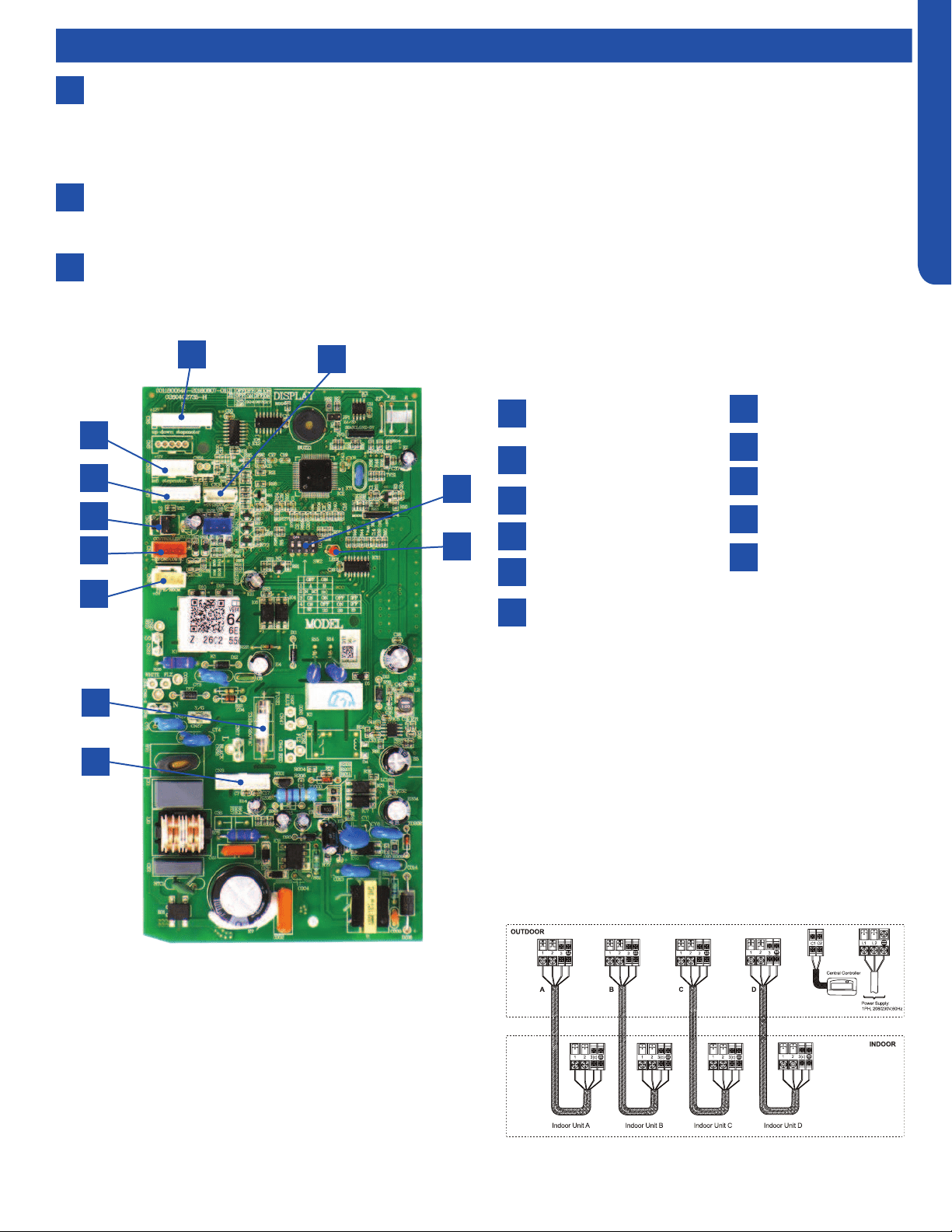
Up/Down Stepper
Motor
Left Stepper Motor
Display Board
Emergency Switch
Wired Controller
Temperature Sensors
15A/250VAC Fuse
DC Fan Motor
LED
DIP Switch Bank SW2
WiFi
Components
6
7
8
Display
The indoor unit has a display that communicates system mode, room temperature and diagnostic code information. The
diagnostic code information shown on the indoor unit will NOT be the same code that is displayed on the outdoor unit.
When servicing a diagnostic error, compare the indoor unit code to the outdoor unit code to make diagnostic decisions.
Codes that relate to outdoor unit problems should use the outdoor unit display information as priority.
Control Board
The indoor unit circuit board controls the switching functions of the indoor unit. All control decisions are made by the
outdoor unit ECU. The indoor board has some limited diagnostic capability which will be covered in this manual.
Evaporator Coil
Indoor Wall Mount Unit Circuit Board
1
2
3
4
5
6
7
8
9
10
11
1
2
3
4
5
6
7
8
10
11
9
The Indoor Unit Circuit Board communicates with the outdoor
unit ECU via a connection at Terminal Block screw 3.
The data pulse that sends the communication information
can be measured with a voltmeter placed to DCV range. From
the ground connection at the Terminal Block to the Number 3
screw connection, the voltage should pulse up and down when
data is being transmitted.
This control board has control over the fan louver movement,
manual fan blower control, indoor coil temperature and indoor
air temperature sensing functions. All operational decisions
are controlled by the OUTDOOR UNIT ECU. The connections
on the indoor board are shown here in the schematic drawing.
Loading ...
Loading ...
Loading ...