Loading ...
Loading ...
Loading ...
TROUBLESHOOTING & REFERENCES
J-10
ENGLISH
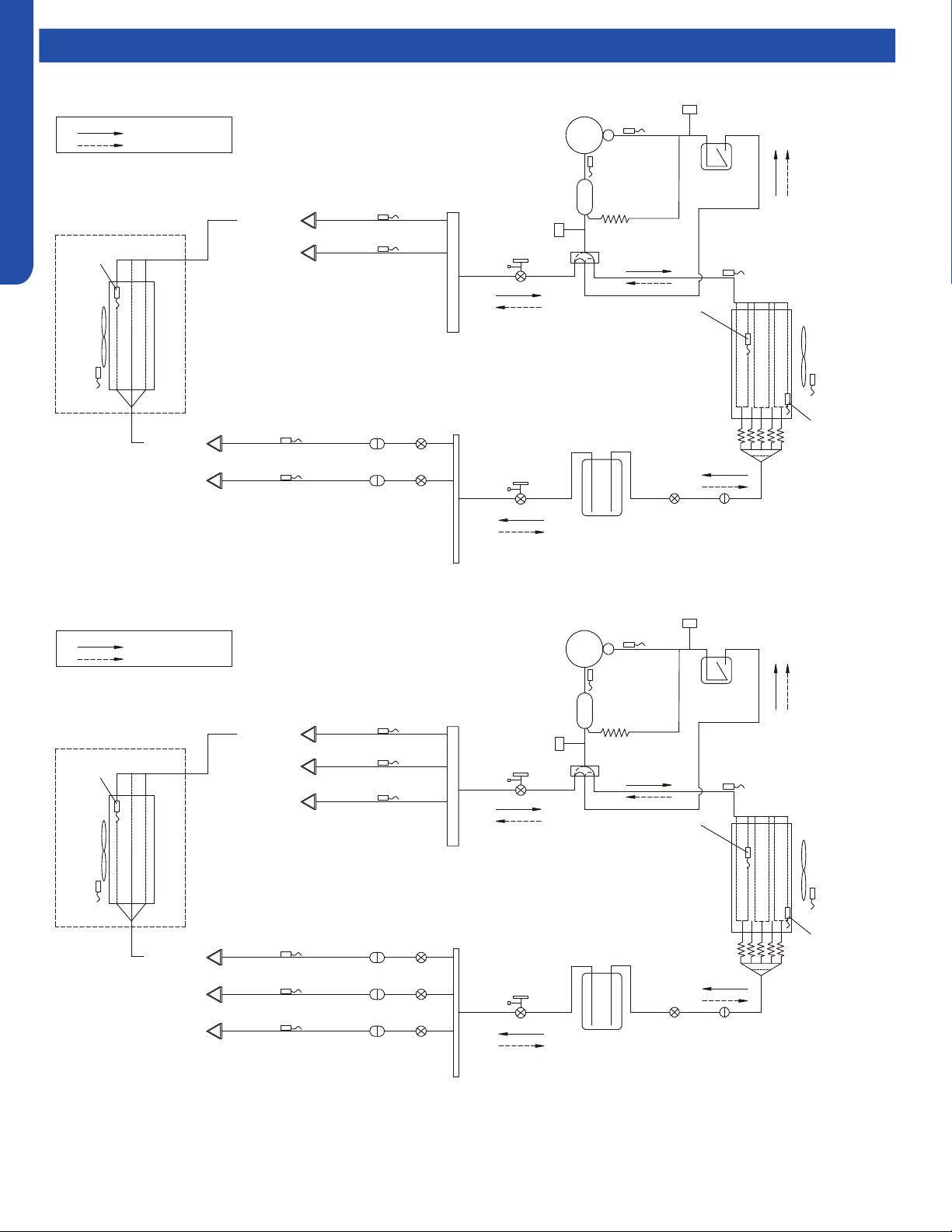
Refrigeration Diagrams
Comp-
●
ressor
Discharge temp.
sensor
Oil
separator
Capillary tube
Ø2.7*Ø1.0*1400
High pressure
switch
4-way valve
Pipe sensor
●
Toci
Suction temp.
sensor
Low pressure
switch
Accumulator
Gas service
valve
Outdoor
he
at
exchanger
temp.
sensor
FAN-OUT
●
Outdoor
ambient
temperature
sensor
Defrost
sensor
Distributor
Strainer
EEV O
Receiver
Liquid service valve
5/8
3/8
Unit A
liquid pipe temp. sensor TC2
Strainer
EEV A
Indoor unit A
Unit B liquid pipe temp. sensor TC2
Strainer
EEV B
Indoor unit B
Unit A gas pipe temp. sensor TC1
Unit B gas pipe temp. sensorTC1
Indoor unit A
Indoor unit B
4-way valve coil:
OFF
ON
Refrigerant flow in cooling
Refrigerant flow in heating
FAN-IN
Indoor
ambient
temperature
sensor
Indoor
heat
exchanger
temp.
sensor
2U20EH2VHA
3U24EH2VHA
Comp-
ressor
D
ischarge temp.
●
sensor
Oil
separator
Capillary tube
Ø2.7*Ø1.0*1400
High pressure
switch
4-way valve
Pipe sensor
Toci
Suction temp.
sensor Ts
Low pressure
switch
Accumulator
Gas service valve
Outdoor
heat
exchanger
temp.
sensor
FAN-OUT
Outdoor
ambient
temperature
sensor Ta
Defrost
sensor Td
Distributor
Strainer
EEV O
Receiver
Liquid service valve
5/8
3/8
Unit A liquid pipe temp. sensor Tc2
Strainer
EEV A
Indoor unit A
Unit B liquid pipe temp. sensorTc2
Strainer
EEV B
Indoor unit B
Unit C liquid pipe temp. sensor Tc2
Strainer
EEV C
Indoor unit C
Unit A gas pipe temp. sensor Tc1
Unit
B gas pipe temp.
sensor Tc1
Unit C gas pipe temp. sensor Tc1
Indoor unit A
Indoor unit B
Indoor unit C
4-way valve coil:
OFF
ON
Refrigerant flow in cooling
Refrigerant flow in heating
FAN-IN
Indoor
ambient
temperature
sensor
Indoor
heat
exchanger
temp.
sensor
Loading ...
Loading ...
Loading ...