Loading ...
Loading ...
Loading ...
WALL MOUNT TECHNICAL OVERVIEW
C-4
ENGLISH
Topic Title
Components
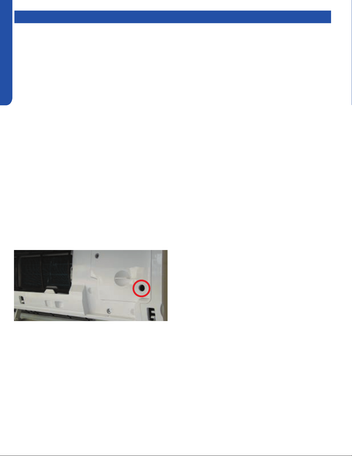
Emergency Run
Switch
Line voltage to power the indoor unit comes in on Terminal
Block connections 1 and 2. Power connects from these
terminal connections on the circuit board. If the board does
not respond to commands and has no display, check for line
voltage at these connections. When power is present at the
indoor board, the RED LED on the circuit board will blink a 2
ash code.
The control board has a replaceable 3.15A 250V fuse that
protects against excessive current. If power is present at
the board but the board does not work, check for continuity
through the fuse. Replace if the fuse is open.
The indoor unit temperature sensors are connected to the
control board. When testing the calibration of these sensors,
the wires can be released from the plug by pressing on the
tension tab on the side of the plug.
The receiver/display unit that is mounted to the front cover of
the indoor unit plugs into the control board.
There are two to three motors connected to the control board
that control the movement of the louvers right, left and up/
down. Some units will use one motor to operate the right and
left movement function.
The blower motor is connected to the circuit board.
There is an Emergency Run switch on the edge of the indoor
board that will put the system into Auto Mode should the
remote control break or be lost. When this switch is pressed
and held for 5 seconds, the indoor unit display will beep twice
and the system will enter TEST MODE.
Loading ...
Loading ...
Loading ...