Loading ...
Loading ...
Loading ...
OUTDOOR TECHNICAL OVERVIEW
B-16
ENGLISH
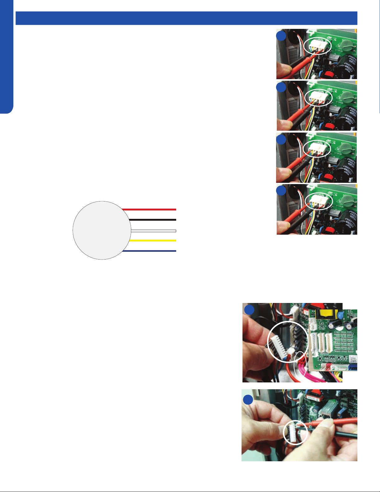
Testing
Outdoor Fan Motor
Check that the wiring and plug connections are in good condition.
If the outdoor unit fan motor does not run, or the Service Monitor Board indicates an error
code of 09, check the following voltages at the motor connector on the outdoor unit PCB. Set
the meter to read DC volts with a minimum voltage range of 350 volts. All voltage values are
approximate. Initiate forced cooling.
1. DC voltage between the Red and Black wire connnections should read 310 ~ 334 VDC. This
is the main voltage for powering the fan motor.
2. DC voltage between the White and Black wire connnections should read 15VDC. This is the
voltage for powering the electronic circuit of the fan motor.
3. DC voltage between the Yellow and Black wire connnections should read 4VDC. The voltage
will read 0VDC when the fan is not being called to operate. This is the control voltage for
regulating the speed of the fan motor.
4. DC voltage between the Blue and Black wire connnections should read 8VDC. The voltage
will read 14VDC when the fan is not being called to operate. (This is the feedback voltage to
the PCB for determining the speed of the fan motor)
If the outdoor fan initially runs, increases speed then stops, and the Service Monitor Board
indicates an error code of 09, the feedback circuit is not functioning. Check that the wiring and
plug connections are in good condition.
Outdoor Fan 310VDC
Pins 1 - 3
Outdoor Fan 15VDC
Pins 3 - 4
Outdoor Fan C
ontrol
Pins 3 - 5
Outdoor Fan Feedback
Pins 3 - 6
Temperature Sensor
The temperature sensors are negative coecient thermistors, in which resistance
decreases as temperature rises. Should the sensors fail, the PCB will generate an
appropriate error code.
To check the calibration of the sensors:
1. Shut o power to the outdoor unit.
2. Disconnect the sensor at the circuit board plug.
3. Measure the temperature of the air surrounding the sensor.
4. Measure the electrical resistance of the sensor using needle probes. Do not
force standard probes into the sensor plug.
5. Compare the measured resistance of the sensor against the resistance/
temperature specications (See chart in reference section)
6. If the sensor resistance is outside of the specication tolerances shown on the
resistance/temperature table, replace the sensor.
1
2
3
4
2
4
DC Motor
+310 VDC
DC Ground
+15 VDC
Signal
Feedback
Red
Black
White
Yellow
Blue
Loading ...
Loading ...
Loading ...