Loading ...
Loading ...
Loading ...
CONSOLE TECHNICAL OVERVIEW
I-7
ENGLISH
Topic Title
Testing
Testing Temperature Sensors
The easiest problems to solve will involve codes that are
related to potential failure of temperature sensors. Common
problems may include loose connections, open electrically,
and out of calibration. Checking the condition of the sensors
requires a temperature probe and an ohmmeter.
The Reference Section of this manual contains temperature
resistance tables that can be used to check the calibration
of the sensors. The measured resistance must be within the
tolerances printed on the top of the tables.
To test the electrical condition of a temperature sensor
perform the following:
1. Conrm the sensor is rmly attached to the circuit board
connection plug.
2. Remove the sensor wires form the connection plug by
releasing holding tension on the plugs tension tab.
3. Use an ohmmeter to test the electrical resistance of the
sensor.
4. Measure the air temperature near the sensor and compare
the required resistance against measured resistance.
(See chart in reference section) If the sensor is within
calibration, the sensor is good. If the sensor is out of
calibration, replace the sensor. (Tube Sensors should be
removed from socket and exposed to air temperature
during test.)
2
4
:
:
Tp
Tr
To Outdoor Unit
L2
L1
SW1
LED5
LED4
250VAC T5A
FUSE
CN20
CN22(22-1)
CN31
CN11
CN35
Main control board
Swing motor
for lower
louver
Swing motor
for upper
louver
CN10
CN6
CN3
CN17
SW2
CN16
CN16-1
W
B
W
BL
BL
W
W
W
YL
BL
W
W
RJ45 BOARD
To RJ45 DEVICE
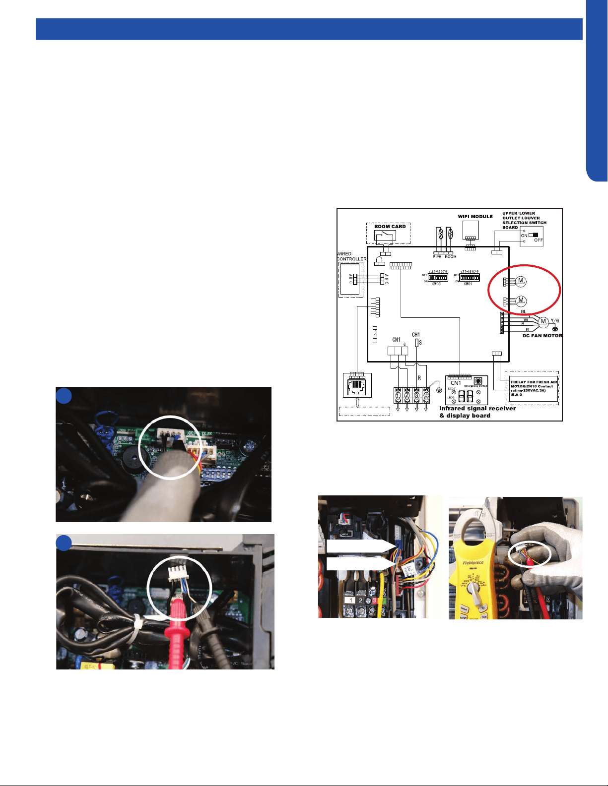
Testing Louver Motors
If the louver does not operate with command from the remote
control, either the indoor board is bad, or the louver motor
is defective. It is more likely the motor is defective than the
board. (Make sure the louver assembly is not binding and
keeping the vanes from moving.)
1. Remove power from the unit and remove the indoor unit
cover.
2. Access the circuit board.
3. Identify the inoperable louver motor on the schematic
drawing below and disconnect the plug from the circuit
board.
4. Use an Ohmmeter to test the electrical continuity of the
louver motor windings. The proper resistance for each
winding should be 292Ω from red wire (common) to any
other wire.. If the motor winding resistance is erratic or
shows open, the motor is defective. Replace the motor.
5. If the motor checks out good, replace the indoor control
board.
Upper Louver
Lower Louver
Loading ...
Loading ...
Loading ...