Loading ...
Loading ...
Loading ...
WALL MOUNT TECHNICAL OVERVIEW
C-8
ENGLISH
Testing
Testing Temperature Sensors
The easiest problems to solve will involve codes that are
related to potential failure of temperature sensors. Common
problems may include loose connections, open electrically,
and out of calibration. Checking the condition of the sensors
requires a temperature probe and an ohmmeter.
The Reference Section of this manual contains temperature
resistance tables that can be used to check the calibration
of the sensors. The measured resistance must be within the
tolerances printed on the top of the tables.
To test the electrical condition of a temperature sensor
perform the following:
1. Conrm the sensor is rmly attached to the circuit
board connection plug.
2. Remove the sensor wires from the connection plug by
releasing holding tension on the plugs tension tab.
3. Use an ohmmeter to test the electrical resistance of the
sensor.
4. Measure the air temperature near the sensor and compare
the required resistance against measured resistance.
(See chart in reference section) If the sensor is within
calibration, the sensor is good. If the sensor is out of
calibration, replace the sensor. (Tube Sensors should be
removed from socket and exposed to air temperature
during test.)
Testing Louver Motors
If the louver does
not operate with
command from the
remote control,
either the indoor
board is bad, or
the louver motor is
defective. It is more
likely the motor is
defective than the board. (Make sure the louver assembly is
not binding and keeping the vanes from moving.)
1. Remove power from the unit and remove the indoor unit
cover.
2. Access the circuit board.
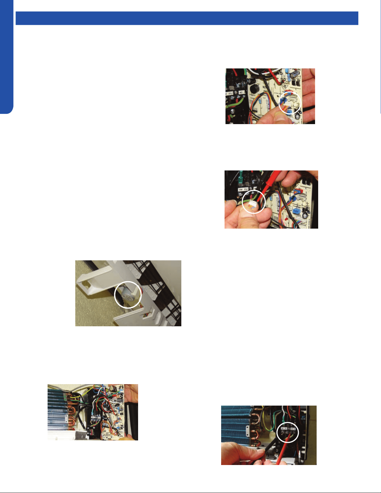
Testing Communication Circuit
If an Error E7 occurs, perform the following test to determine
if the indoor control board is functioning properly to send data
to the outdoor unit.
Perform this test with the unit powered and all wiring
connected between indoor and outdoor unit.
Make sure all wiring between the indoor and outdoor unit
are correct. There should no splices between the indoor and
outdoor unit wiring connecting terminals 1 or 3. Make sure
wiring is correct, before performing this test.
1. Measure the DC voltage between terminals 1 and 3 on the
indoor terminal block.
2. C and 23VDC. The uctuating signal indicates a good
communication path.
3. If the voltage does not uctuate, and the wiring is good,
the indoor board is defective.
3. Identify on the schematic drawing the inoperable louver
motor and disconnect the plug from the circuit board. (The
up down louver motor is located on the right side of the
indoor unit. The left right louver motor is located bottom
center. )
4. Use an Ohmmeter to test the electrical continuity of the
louver motor windings. The proper resistance for each
winding can be found in this table. If the motor winding
resistance is erratic or shows open, the motor is defective.
Replace the motor.
5. If the motor checks out good, replace the indoor control
board.
Loading ...
Loading ...
Loading ...