Loading ...
Loading ...
Loading ...
OUTDOOR TECHNICAL OVERVIEW
B-5
ENGLISH
Components
A replaceable, 30A, 250V rated
ceramic fuse protects the outdoor
unit electronics. The fuse will open if
a power surge or internal short in the
outdoor unit has occurred.
The PFB receives line voltage at
terminals P1 and P2 from the outdoor
unit high voltage terminal block 1/N
and 2/L.
The voltage that powers the indoor
units connects to terminals P3 and P4.
The PCB receives power to operate
via connections at terminals P5 and
P6.
The IPM receives power via connections at terminals P7 and terminal 3.
There is a communication plug labeled CN-1 on the PFB. This plug connects from the PFB to the PCB. If this cable is
disconnected or loose, the system will generate a Code 6 module low or high voltage error. This error will not be displayed
in memory on the indoor unit wired controller. CN-1 and CN-2 connect to the PCB at terminals CN-6 and CN-34. CN-6 is
the low stand-by power connection. When power has been turned o at the controller for 5 minutes, CN-6 will remove the
12 VDC signal and open relay RL-1 on the PFB. This saves energy by shutting o power to the IPM. The capacitors must
have current ow before the compressor can start. CN-34 is the capacitor charging circuit. When the capacitors are fully
charged, the circuit opens to stop the charging process via the RL-2 relay. The voltage between the two pins of CN-1 and
the two pins of CN-2 is 12 VDC.
2
2
6
4
4
3
3
5
1
1
The purpose of the PFB is to lter out potential electrical noise before it reaches the outdoor unit electronic circuits. All voltage
to operate the outdoor unit circuits must pass through the PFB.
1
2
6
4
5
3
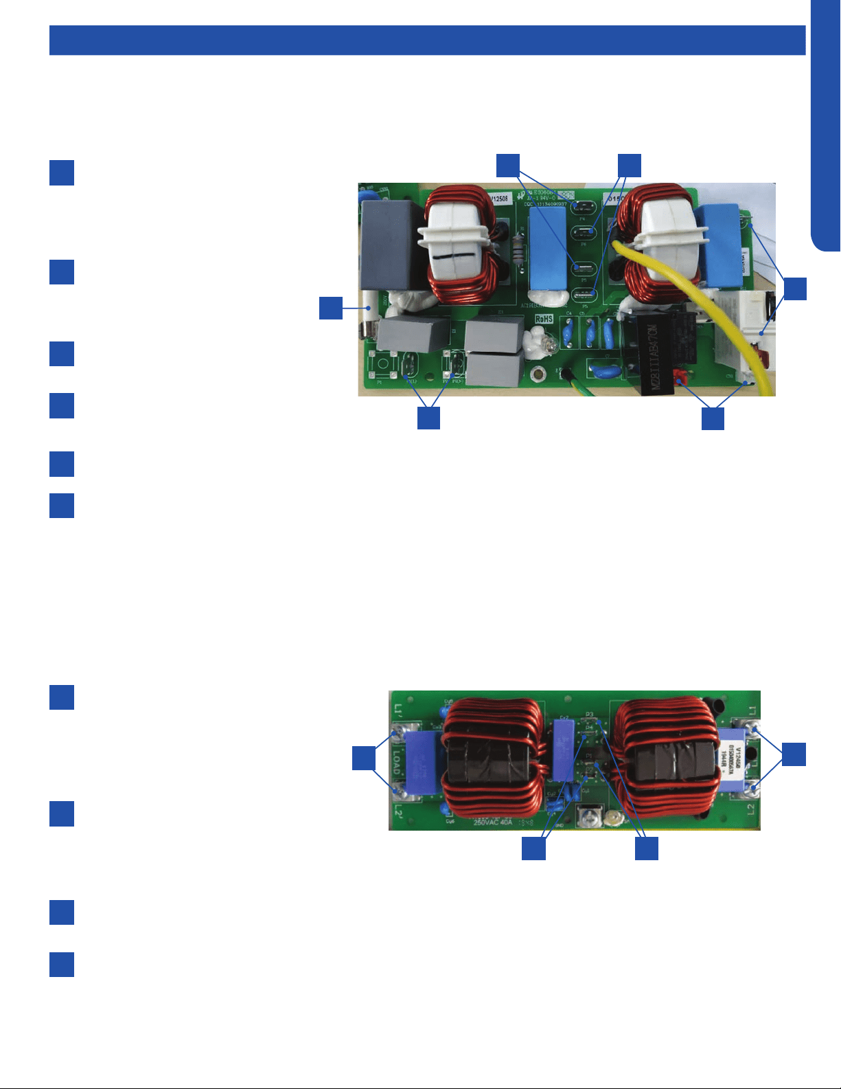
Power Filter Board (PFB)
2U & 3U
4U
L1 & L2 is the input port of Filter Board,
they will provide 208/230Vac, 60Hz power
to the whole unit group(outdoor unit
&indoor unit ),as is shown in the wiring
diagram, these two terminal connect to the
OUD main power supply terminal block.
P1 & P3 is the one of the rst stage ltered
output of the Filter Board, they will provide
208/230Vac, 60Hz power to all the indoor
units which connect to the outdoor unit. As
is shown in the wiring diagram, these two terminals connect to one of the IDU & OUD connection terminal block.
P2 & P4 is the other one of the rst stage ltered output of the Filter Board, they will provide 208/230Vac, 60Hz power to
the main control board. As is shown in the wiring diagram, these two terminals connect to the ODU main control board CN2
L1 & L2 is the 2nd stage ltered output of the Filter Board, they will provide 208/230Vac, 60Hz power to the compressor
drive module (inverter board). As is shown in the wiring diagram, these two terminals compressor drive module’s power
input L1 & L2.
1
23
4
Loading ...
Loading ...
Loading ...